EP3038159A2 - Thin film transistor substrate and method of manufacturing the same - Google Patents
Thin film transistor substrate and method of manufacturing the same Download PDFInfo
- Publication number
- EP3038159A2 EP3038159A2 EP15197918.4A EP15197918A EP3038159A2 EP 3038159 A2 EP3038159 A2 EP 3038159A2 EP 15197918 A EP15197918 A EP 15197918A EP 3038159 A2 EP3038159 A2 EP 3038159A2
- Authority
- EP
- European Patent Office
- Prior art keywords
- layer
- buffer layer
- passivation layer
- sub
- electric power
- Prior art date
- Legal status (The legal status is an assumption and is not a legal conclusion. Google has not performed a legal analysis and makes no representation as to the accuracy of the status listed.)
- Withdrawn
Links
- 239000000758 substrate Substances 0.000 title claims abstract description 126
- 239000010409 thin film Substances 0.000 title claims abstract description 94
- 238000004519 manufacturing process Methods 0.000 title claims description 24
- 238000002161 passivation Methods 0.000 claims abstract description 443
- 229910052739 hydrogen Inorganic materials 0.000 claims abstract description 148
- UFHFLCQGNIYNRP-UHFFFAOYSA-N Hydrogen Chemical compound [H][H] UFHFLCQGNIYNRP-UHFFFAOYSA-N 0.000 claims abstract description 147
- 239000001257 hydrogen Substances 0.000 claims abstract description 147
- 229910052751 metal Inorganic materials 0.000 claims abstract description 104
- 239000002184 metal Substances 0.000 claims abstract description 104
- 229910052814 silicon oxide Inorganic materials 0.000 claims description 265
- VYPSYNLAJGMNEJ-UHFFFAOYSA-N Silicium dioxide Chemical compound O=[Si]=O VYPSYNLAJGMNEJ-UHFFFAOYSA-N 0.000 claims description 246
- 238000009832 plasma treatment Methods 0.000 claims description 88
- 238000000034 method Methods 0.000 claims description 77
- AMWRITDGCCNYAT-UHFFFAOYSA-L hydroxy(oxo)manganese;manganese Chemical compound [Mn].O[Mn]=O.O[Mn]=O AMWRITDGCCNYAT-UHFFFAOYSA-L 0.000 claims description 76
- 238000009413 insulation Methods 0.000 claims description 75
- OGIDPMRJRNCKJF-UHFFFAOYSA-N titanium oxide Inorganic materials [Ti]=O OGIDPMRJRNCKJF-UHFFFAOYSA-N 0.000 claims description 62
- GWEVSGVZZGPLCZ-UHFFFAOYSA-N Titan oxide Chemical compound O=[Ti]=O GWEVSGVZZGPLCZ-UHFFFAOYSA-N 0.000 claims description 50
- AJNVQOSZGJRYEI-UHFFFAOYSA-N digallium;oxygen(2-) Chemical compound [O-2].[O-2].[O-2].[Ga+3].[Ga+3] AJNVQOSZGJRYEI-UHFFFAOYSA-N 0.000 claims description 38
- 229910001195 gallium oxide Inorganic materials 0.000 claims description 38
- TWNQGVIAIRXVLR-UHFFFAOYSA-N oxo(oxoalumanyloxy)alumane Chemical compound O=[Al]O[Al]=O TWNQGVIAIRXVLR-UHFFFAOYSA-N 0.000 claims description 38
- BPUBBGLMJRNUCC-UHFFFAOYSA-N oxygen(2-);tantalum(5+) Chemical compound [O-2].[O-2].[O-2].[O-2].[O-2].[Ta+5].[Ta+5] BPUBBGLMJRNUCC-UHFFFAOYSA-N 0.000 claims description 38
- 229910001936 tantalum oxide Inorganic materials 0.000 claims description 38
- GYHNNYVSQQEPJS-UHFFFAOYSA-N Gallium Chemical compound [Ga] GYHNNYVSQQEPJS-UHFFFAOYSA-N 0.000 claims description 31
- 229910052733 gallium Inorganic materials 0.000 claims description 31
- 229910052782 aluminium Inorganic materials 0.000 claims description 28
- XAGFODPZIPBFFR-UHFFFAOYSA-N aluminium Chemical compound [Al] XAGFODPZIPBFFR-UHFFFAOYSA-N 0.000 claims description 28
- 229910052710 silicon Inorganic materials 0.000 claims description 26
- XUIMIQQOPSSXEZ-UHFFFAOYSA-N Silicon Chemical compound [Si] XUIMIQQOPSSXEZ-UHFFFAOYSA-N 0.000 claims description 25
- 239000010703 silicon Substances 0.000 claims description 25
- 239000010410 layer Substances 0.000 description 1000
- XLOMVQKBTHCTTD-UHFFFAOYSA-N Zinc monoxide Chemical compound [Zn]=O XLOMVQKBTHCTTD-UHFFFAOYSA-N 0.000 description 72
- 239000012044 organic layer Substances 0.000 description 60
- 239000000463 material Substances 0.000 description 56
- 229910052581 Si3N4 Inorganic materials 0.000 description 45
- 229910010272 inorganic material Inorganic materials 0.000 description 45
- 239000011147 inorganic material Substances 0.000 description 45
- HQVNEWCFYHHQES-UHFFFAOYSA-N silicon nitride Chemical compound N12[Si]34N5[Si]62N3[Si]51N64 HQVNEWCFYHHQES-UHFFFAOYSA-N 0.000 description 45
- 239000004065 semiconductor Substances 0.000 description 42
- 239000010949 copper Substances 0.000 description 36
- 239000011787 zinc oxide Substances 0.000 description 36
- 239000010936 titanium Substances 0.000 description 33
- QVGXLLKOCUKJST-UHFFFAOYSA-N atomic oxygen Chemical compound [O] QVGXLLKOCUKJST-UHFFFAOYSA-N 0.000 description 28
- 239000001301 oxygen Substances 0.000 description 28
- 229910052760 oxygen Inorganic materials 0.000 description 28
- RYGMFSIKBFXOCR-UHFFFAOYSA-N Copper Chemical compound [Cu] RYGMFSIKBFXOCR-UHFFFAOYSA-N 0.000 description 27
- 229910052802 copper Inorganic materials 0.000 description 27
- 230000006866 deterioration Effects 0.000 description 26
- 239000000969 carrier Substances 0.000 description 23
- RTAQQCXQSZGOHL-UHFFFAOYSA-N Titanium Chemical compound [Ti] RTAQQCXQSZGOHL-UHFFFAOYSA-N 0.000 description 21
- 229910052719 titanium Inorganic materials 0.000 description 21
- YVTHLONGBIQYBO-UHFFFAOYSA-N zinc indium(3+) oxygen(2-) Chemical compound [O--].[Zn++].[In+3] YVTHLONGBIQYBO-UHFFFAOYSA-N 0.000 description 21
- 239000011572 manganese Substances 0.000 description 18
- 229910052738 indium Inorganic materials 0.000 description 12
- APFVFJFRJDLVQX-UHFFFAOYSA-N indium atom Chemical compound [In] APFVFJFRJDLVQX-UHFFFAOYSA-N 0.000 description 12
- 229910003437 indium oxide Inorganic materials 0.000 description 12
- PJXISJQVUVHSOJ-UHFFFAOYSA-N indium(iii) oxide Chemical compound [O-2].[O-2].[O-2].[In+3].[In+3] PJXISJQVUVHSOJ-UHFFFAOYSA-N 0.000 description 12
- HRHKULZDDYWVBE-UHFFFAOYSA-N indium;oxozinc;tin Chemical compound [In].[Sn].[Zn]=O HRHKULZDDYWVBE-UHFFFAOYSA-N 0.000 description 12
- KYKLWYKWCAYAJY-UHFFFAOYSA-N oxotin;zinc Chemical compound [Zn].[Sn]=O KYKLWYKWCAYAJY-UHFFFAOYSA-N 0.000 description 12
- 239000000203 mixture Substances 0.000 description 10
- VYZAMTAEIAYCRO-UHFFFAOYSA-N Chromium Chemical compound [Cr] VYZAMTAEIAYCRO-UHFFFAOYSA-N 0.000 description 9
- PWHULOQIROXLJO-UHFFFAOYSA-N Manganese Chemical compound [Mn] PWHULOQIROXLJO-UHFFFAOYSA-N 0.000 description 9
- ZOKXTWBITQBERF-UHFFFAOYSA-N Molybdenum Chemical compound [Mo] ZOKXTWBITQBERF-UHFFFAOYSA-N 0.000 description 9
- BQCADISMDOOEFD-UHFFFAOYSA-N Silver Chemical compound [Ag] BQCADISMDOOEFD-UHFFFAOYSA-N 0.000 description 9
- 239000004020 conductor Substances 0.000 description 9
- AMGQUBHHOARCQH-UHFFFAOYSA-N indium;oxotin Chemical compound [In].[Sn]=O AMGQUBHHOARCQH-UHFFFAOYSA-N 0.000 description 9
- 229910052748 manganese Inorganic materials 0.000 description 9
- 229910052750 molybdenum Inorganic materials 0.000 description 9
- 239000011733 molybdenum Substances 0.000 description 9
- 239000011368 organic material Substances 0.000 description 9
- 229910052709 silver Inorganic materials 0.000 description 9
- 239000004332 silver Substances 0.000 description 9
- 239000002356 single layer Substances 0.000 description 9
- 235000012239 silicon dioxide Nutrition 0.000 description 7
- 239000011521 glass Substances 0.000 description 6
- ZPZCREMGFMRIRR-UHFFFAOYSA-N molybdenum titanium Chemical compound [Ti].[Mo] ZPZCREMGFMRIRR-UHFFFAOYSA-N 0.000 description 6
- 239000010453 quartz Substances 0.000 description 6
- 229910021420 polycrystalline silicon Inorganic materials 0.000 description 4
- 229910021417 amorphous silicon Inorganic materials 0.000 description 3
- 230000007547 defect Effects 0.000 description 3
- 238000012986 modification Methods 0.000 description 3
- 230000004048 modification Effects 0.000 description 3
- 230000003252 repetitive effect Effects 0.000 description 3
- BLRPTPMANUNPDV-UHFFFAOYSA-N Silane Chemical compound [SiH4] BLRPTPMANUNPDV-UHFFFAOYSA-N 0.000 description 2
- 238000006243 chemical reaction Methods 0.000 description 2
- 230000015572 biosynthetic process Effects 0.000 description 1
- 229910052681 coesite Inorganic materials 0.000 description 1
- 229910052906 cristobalite Inorganic materials 0.000 description 1
- 238000002425 crystallisation Methods 0.000 description 1
- 230000008025 crystallization Effects 0.000 description 1
- 239000000377 silicon dioxide Substances 0.000 description 1
- 229910052682 stishovite Inorganic materials 0.000 description 1
- 239000000126 substance Substances 0.000 description 1
- 239000012780 transparent material Substances 0.000 description 1
- 229910052905 tridymite Inorganic materials 0.000 description 1
Images


Classifications
-
- H—ELECTRICITY
- H01—ELECTRIC ELEMENTS
- H01L—SEMICONDUCTOR DEVICES NOT COVERED BY CLASS H10
- H01L29/00—Semiconductor devices adapted for rectifying, amplifying, oscillating or switching, or capacitors or resistors with at least one potential-jump barrier or surface barrier, e.g. PN junction depletion layer or carrier concentration layer; Details of semiconductor bodies or of electrodes thereof ; Multistep manufacturing processes therefor
- H01L29/66—Types of semiconductor device ; Multistep manufacturing processes therefor
- H01L29/68—Types of semiconductor device ; Multistep manufacturing processes therefor controllable by only the electric current supplied, or only the electric potential applied, to an electrode which does not carry the current to be rectified, amplified or switched
- H01L29/76—Unipolar devices, e.g. field effect transistors
- H01L29/772—Field effect transistors
- H01L29/78—Field effect transistors with field effect produced by an insulated gate
- H01L29/786—Thin film transistors, i.e. transistors with a channel being at least partly a thin film
- H01L29/7869—Thin film transistors, i.e. transistors with a channel being at least partly a thin film having a semiconductor body comprising an oxide semiconductor material, e.g. zinc oxide, copper aluminium oxide, cadmium stannate
-
- H—ELECTRICITY
- H01—ELECTRIC ELEMENTS
- H01L—SEMICONDUCTOR DEVICES NOT COVERED BY CLASS H10
- H01L21/00—Processes or apparatus adapted for the manufacture or treatment of semiconductor or solid state devices or of parts thereof
- H01L21/02—Manufacture or treatment of semiconductor devices or of parts thereof
- H01L21/02104—Forming layers
- H01L21/02107—Forming insulating materials on a substrate
- H01L21/02109—Forming insulating materials on a substrate characterised by the type of layer, e.g. type of material, porous/non-porous, pre-cursors, mixtures or laminates
- H01L21/02112—Forming insulating materials on a substrate characterised by the type of layer, e.g. type of material, porous/non-porous, pre-cursors, mixtures or laminates characterised by the material of the layer
- H01L21/02123—Forming insulating materials on a substrate characterised by the type of layer, e.g. type of material, porous/non-porous, pre-cursors, mixtures or laminates characterised by the material of the layer the material containing silicon
- H01L21/02126—Forming insulating materials on a substrate characterised by the type of layer, e.g. type of material, porous/non-porous, pre-cursors, mixtures or laminates characterised by the material of the layer the material containing silicon the material containing Si, O, and at least one of H, N, C, F, or other non-metal elements, e.g. SiOC, SiOC:H or SiONC
-
- H—ELECTRICITY
- H01—ELECTRIC ELEMENTS
- H01L—SEMICONDUCTOR DEVICES NOT COVERED BY CLASS H10
- H01L21/00—Processes or apparatus adapted for the manufacture or treatment of semiconductor or solid state devices or of parts thereof
- H01L21/02—Manufacture or treatment of semiconductor devices or of parts thereof
- H01L21/02104—Forming layers
- H01L21/02107—Forming insulating materials on a substrate
- H01L21/02109—Forming insulating materials on a substrate characterised by the type of layer, e.g. type of material, porous/non-porous, pre-cursors, mixtures or laminates
- H01L21/022—Forming insulating materials on a substrate characterised by the type of layer, e.g. type of material, porous/non-porous, pre-cursors, mixtures or laminates the layer being a laminate, i.e. composed of sublayers, e.g. stacks of alternating high-k metal oxides
-
- H—ELECTRICITY
- H01—ELECTRIC ELEMENTS
- H01L—SEMICONDUCTOR DEVICES NOT COVERED BY CLASS H10
- H01L21/00—Processes or apparatus adapted for the manufacture or treatment of semiconductor or solid state devices or of parts thereof
- H01L21/02—Manufacture or treatment of semiconductor devices or of parts thereof
- H01L21/02104—Forming layers
- H01L21/02107—Forming insulating materials on a substrate
- H01L21/02225—Forming insulating materials on a substrate characterised by the process for the formation of the insulating layer
- H01L21/02227—Forming insulating materials on a substrate characterised by the process for the formation of the insulating layer formation by a process other than a deposition process
- H01L21/02252—Forming insulating materials on a substrate characterised by the process for the formation of the insulating layer formation by a process other than a deposition process formation by plasma treatment, e.g. plasma oxidation of the substrate
-
- H—ELECTRICITY
- H01—ELECTRIC ELEMENTS
- H01L—SEMICONDUCTOR DEVICES NOT COVERED BY CLASS H10
- H01L21/00—Processes or apparatus adapted for the manufacture or treatment of semiconductor or solid state devices or of parts thereof
- H01L21/02—Manufacture or treatment of semiconductor devices or of parts thereof
- H01L21/02104—Forming layers
- H01L21/02107—Forming insulating materials on a substrate
- H01L21/02225—Forming insulating materials on a substrate characterised by the process for the formation of the insulating layer
- H01L21/0226—Forming insulating materials on a substrate characterised by the process for the formation of the insulating layer formation by a deposition process
- H01L21/02263—Forming insulating materials on a substrate characterised by the process for the formation of the insulating layer formation by a deposition process deposition from the gas or vapour phase
- H01L21/02271—Forming insulating materials on a substrate characterised by the process for the formation of the insulating layer formation by a deposition process deposition from the gas or vapour phase deposition by decomposition or reaction of gaseous or vapour phase compounds, i.e. chemical vapour deposition
- H01L21/02274—Forming insulating materials on a substrate characterised by the process for the formation of the insulating layer formation by a deposition process deposition from the gas or vapour phase deposition by decomposition or reaction of gaseous or vapour phase compounds, i.e. chemical vapour deposition in the presence of a plasma [PECVD]
-
- H—ELECTRICITY
- H01—ELECTRIC ELEMENTS
- H01L—SEMICONDUCTOR DEVICES NOT COVERED BY CLASS H10
- H01L21/00—Processes or apparatus adapted for the manufacture or treatment of semiconductor or solid state devices or of parts thereof
- H01L21/02—Manufacture or treatment of semiconductor devices or of parts thereof
- H01L21/04—Manufacture or treatment of semiconductor devices or of parts thereof the devices having at least one potential-jump barrier or surface barrier, e.g. PN junction, depletion layer or carrier concentration layer
- H01L21/34—Manufacture or treatment of semiconductor devices or of parts thereof the devices having at least one potential-jump barrier or surface barrier, e.g. PN junction, depletion layer or carrier concentration layer the devices having semiconductor bodies not provided for in groups H01L21/0405, H01L21/0445, H01L21/06, H01L21/16 and H01L21/18 with or without impurities, e.g. doping materials
- H01L21/46—Treatment of semiconductor bodies using processes or apparatus not provided for in groups H01L21/428
- H01L21/461—Treatment of semiconductor bodies using processes or apparatus not provided for in groups H01L21/428 to change their surface-physical characteristics or shape, e.g. etching, polishing, cutting
- H01L21/469—Treatment of semiconductor bodies using processes or apparatus not provided for in groups H01L21/428 to change their surface-physical characteristics or shape, e.g. etching, polishing, cutting to form insulating layers thereon, e.g. for masking or by using photolithographic techniques; After-treatment of these layers
- H01L21/471—Inorganic layers
-
- H—ELECTRICITY
- H01—ELECTRIC ELEMENTS
- H01L—SEMICONDUCTOR DEVICES NOT COVERED BY CLASS H10
- H01L29/00—Semiconductor devices adapted for rectifying, amplifying, oscillating or switching, or capacitors or resistors with at least one potential-jump barrier or surface barrier, e.g. PN junction depletion layer or carrier concentration layer; Details of semiconductor bodies or of electrodes thereof ; Multistep manufacturing processes therefor
- H01L29/40—Electrodes ; Multistep manufacturing processes therefor
- H01L29/41—Electrodes ; Multistep manufacturing processes therefor characterised by their shape, relative sizes or dispositions
- H01L29/423—Electrodes ; Multistep manufacturing processes therefor characterised by their shape, relative sizes or dispositions not carrying the current to be rectified, amplified or switched
- H01L29/42312—Gate electrodes for field effect devices
- H01L29/42316—Gate electrodes for field effect devices for field-effect transistors
- H01L29/4232—Gate electrodes for field effect devices for field-effect transistors with insulated gate
- H01L29/42384—Gate electrodes for field effect devices for field-effect transistors with insulated gate for thin film field effect transistors, e.g. characterised by the thickness or the shape of the insulator or the dimensions, the shape or the lay-out of the conductor
-
- H—ELECTRICITY
- H01—ELECTRIC ELEMENTS
- H01L—SEMICONDUCTOR DEVICES NOT COVERED BY CLASS H10
- H01L29/00—Semiconductor devices adapted for rectifying, amplifying, oscillating or switching, or capacitors or resistors with at least one potential-jump barrier or surface barrier, e.g. PN junction depletion layer or carrier concentration layer; Details of semiconductor bodies or of electrodes thereof ; Multistep manufacturing processes therefor
- H01L29/66—Types of semiconductor device ; Multistep manufacturing processes therefor
- H01L29/66007—Multistep manufacturing processes
- H01L29/66075—Multistep manufacturing processes of devices having semiconductor bodies comprising group 14 or group 13/15 materials
- H01L29/66227—Multistep manufacturing processes of devices having semiconductor bodies comprising group 14 or group 13/15 materials the devices being controllable only by the electric current supplied or the electric potential applied, to an electrode which does not carry the current to be rectified, amplified or switched, e.g. three-terminal devices
- H01L29/66409—Unipolar field-effect transistors
- H01L29/66477—Unipolar field-effect transistors with an insulated gate, i.e. MISFET
- H01L29/66742—Thin film unipolar transistors
-
- H—ELECTRICITY
- H01—ELECTRIC ELEMENTS
- H01L—SEMICONDUCTOR DEVICES NOT COVERED BY CLASS H10
- H01L29/00—Semiconductor devices adapted for rectifying, amplifying, oscillating or switching, or capacitors or resistors with at least one potential-jump barrier or surface barrier, e.g. PN junction depletion layer or carrier concentration layer; Details of semiconductor bodies or of electrodes thereof ; Multistep manufacturing processes therefor
- H01L29/66—Types of semiconductor device ; Multistep manufacturing processes therefor
- H01L29/66007—Multistep manufacturing processes
- H01L29/66969—Multistep manufacturing processes of devices having semiconductor bodies not comprising group 14 or group 13/15 materials
-
- H—ELECTRICITY
- H01—ELECTRIC ELEMENTS
- H01L—SEMICONDUCTOR DEVICES NOT COVERED BY CLASS H10
- H01L29/00—Semiconductor devices adapted for rectifying, amplifying, oscillating or switching, or capacitors or resistors with at least one potential-jump barrier or surface barrier, e.g. PN junction depletion layer or carrier concentration layer; Details of semiconductor bodies or of electrodes thereof ; Multistep manufacturing processes therefor
- H01L29/66—Types of semiconductor device ; Multistep manufacturing processes therefor
- H01L29/68—Types of semiconductor device ; Multistep manufacturing processes therefor controllable by only the electric current supplied, or only the electric potential applied, to an electrode which does not carry the current to be rectified, amplified or switched
- H01L29/76—Unipolar devices, e.g. field effect transistors
- H01L29/772—Field effect transistors
- H01L29/78—Field effect transistors with field effect produced by an insulated gate
- H01L29/786—Thin film transistors, i.e. transistors with a channel being at least partly a thin film
- H01L29/78606—Thin film transistors, i.e. transistors with a channel being at least partly a thin film with supplementary region or layer in the thin film or in the insulated bulk substrate supporting it for controlling or increasing the safety of the device
- H01L29/78618—Thin film transistors, i.e. transistors with a channel being at least partly a thin film with supplementary region or layer in the thin film or in the insulated bulk substrate supporting it for controlling or increasing the safety of the device characterised by the drain or the source properties, e.g. the doping structure, the composition, the sectional shape or the contact structure
Definitions
- Exemplary embodiments of the present inventive concept relate generally to thin film transistors. More particularly, exemplary embodiments relate to thin film transistor substrates that may be used for display devices, and methods of their manufacture.
- a thin film transistor for driving a pixel unit in a display device includes a gate electrode, a source electrode, a drain electrode, and an active pattern forming a channel between the source electrode and the drain electrode.
- the active pattern includes a semiconductor layer including amorphous silicon, polycrystalline silicon, an oxide semiconductor, or the like.
- Amorphous silicon has a relatively low electron mobility, which may be about 1 to about 10cm 2 /V, so that an amorphous silicon thin film transistor has relatively low driving characteristics.
- polycrystalline silicon has a relatively high electron mobility, which may be about 10 to about hundreds of cm 2 /V.
- Oxide semiconductors may be formed through a low-temperature process that is relatively easily scaled up, and have a high electron mobility. Thus, research is actively being conducted on thin film transistors which include an oxide semiconductor.
- ionized atoms may impact the oxide semiconductors. This may generate defects within the oxide semiconductors. This in turn may manifest as defects in the display apparatus.
- Exemplary embodiments of the present inventive concept provide a thin film transistor substrate having fewer defects.
- Exemplary embodiments of the present inventive concept further provide a method of manufacturing the thin film transistor substrate.
- the thin film transistor substrate includes a gate electrode disposed on a base substrate, an active pattern overlapping the gate electrode, a source metal pattern comprising both a source electrode disposed on the active pattern and a drain electrode spaced apart from the source electrode, a buffer layer disposed on the source metal pattern and contacting the active pattern, a first passivation layer disposed on the buffer layer and a second passivation layer disposed on the first passivation layer.
- the density of hydrogen in the buffer layer is greater than the density of hydrogen in the first passivation layer and less than the density of hydrogen in the second passivation layer.
- the buffer layer may include a silicon oxide (SiOx), an aluminum oxide (AlOx), a gallium oxide (GaOx), a titanium oxide (TiOx), a tantalum oxide (TaOx), a manganese oxide (MnOx), a silicon oxynitride (SiON), an aluminum oxynitride (AlON) or a gallium oxynitride (GaON).
- SiOx silicon oxide
- AlOx aluminum oxide
- GaOx gallium oxide
- TiOx titanium oxide
- TaOx tantalum oxide
- MnOx manganese oxide
- SiON silicon oxynitride
- AlON aluminum oxynitride
- GaON gallium oxynitride
- the buffer layer may include a first sub buffer layer contacting the active pattern, a second sub buffer layer disposed on the first sub buffer layer and a third sub buffer layer disposed on the second sub buffer layer and contacting the first passivation layer.
- the density of hydrogen contained in the first sub buffer layer may be greater than the density of hydrogen in the second sub buffer layer.
- the density of hydrogen in the second sub buffer layer may be greater than the density of hydrogen in the third sub buffer layer.
- the first sub buffer layer, the second sub buffer layer and the third sub buffer layer may each include the same material.
- the first sub buffer layer, the second sub buffer layer, the third sub buffer layer and the first passivation layer may each include the same material.
- the thin film transistor substrate may further include an insulation layer disposed on the gate electrode and a lower buffer layer disposed between the insulation layer and the active pattern.
- the density of hydrogen in the lower buffer layer may be greater than the density of hydrogen in the first passivation layer.
- the method includes forming a gate electrode on a base substrate, forming an insulation layer on the gate electrode, forming an active pattern on the insulation layer, forming a metal pattern on the active pattern, the metal pattern comprising a source electrode and a drain electrode spaced apart from the source electrode on the active pattern, forming a buffer layer on the source metal pattern, forming a first passivation layer on the buffer layer and forming a second passivation layer on the first passivation layer.
- the forming a buffer layer includes performing a plasma treatment using a first electric power.
- the forming a first passivation layer includes performing a plasma treatment using a second electric power higher than the first electric power.
- the forming a second passivation layer includes performing a plasma treatment using a third electric power higher than the second electric power.
- the first electric power may be greater than 0.5kW and less than 1.5kW.
- the second electric power may be greater than 3.5kW and less than 4.5kW.
- the third electric power may be greater than 7.5kW and less than 8.5kW
- a density of hydrogen in the buffer layer may be greater than the density of hydrogen in the first passivation layer and less than the density of hydrogen in the second passivation layer.
- the buffer layer may include silicon oxide (SiOx), aluminum oxide (AlOx), gallium oxide (GaOx), titanium oxide (TiOx), tantalum oxide (TaOx), manganese oxide (MnOx), silicon oxynitride (SiON), aluminum oxynitride (AlON) or gallium oxynitride (GaON).
- the forming a buffer layer may further include forming a first sub buffer layer on the active pattern, forming a second sub buffer layer on the first sub buffer layer and forming a third sub buffer layer on the second sub buffer layer.
- the forming a first passivation layer may further comprise forming the first passivation layer so as to contact the third sub buffer layer.
- the forming a third sub buffer layer may include performing a plasma treatment using a first electric power.
- the forming a second sub buffer layer may include performing a plasma treatment using a fourth electric power lower than the first electric power.
- the forming a first sub buffer layer may include performing a plasma treatment using a fifth electric power lower than the fourth electric power.
- a density of hydrogen in the first sub buffer layer may be greater than the density of hydrogen contained in the second sub buffer layer.
- the density of hydrogen in the second sub buffer layer may be greater than the density of hydrogen in the third sub buffer layer.
- the first sub buffer layer, the second sub buffer layer and the third sub buffer layer may each include the same material.
- the first sub buffer layer, the second sub buffer layer, the third sub buffer layer and the first passivation layer may each include the same material.
- the method may further include forming a lower buffer layer on the insulation layer.
- the forming a lower buffer layer may include performing a plasma treatment using the first electric power.
- a density of hydrogen in the lower buffer layer may be greater than the density of hydrogen in the first passivation layer.
- a buffer layer is formed by using a relatively low electric power, so that deterioration of the active pattern and the source metal pattern may be minimized.
- the buffer layer includes silicon oxide (SiOx) and is formed using a low electric power, H 2 SiOx may be generated.
- SiOx silicon oxide
- H 2 SiOx may be generated.
- an amount, or density, of hydrogen in the buffer layer may be increased. Accordingly, oxygen may be provided to the active pattern, so that carriers may be increased in the active pattern.
- a thin film transistor substrate according to an exemplary embodiment of the inventive concept further includes a lower buffer layer disposed between the gate insulation layer and the active pattern. Accordingly, the lower buffer layer provides the active pattern with oxygen, so that carriers may be further increased in the active pattern.
- the thin film transistor substrate of the present invention especially is a display substrate which may be used for a display device.
- FIG. 1 is a plan view illustrating a thin film transistor substrate according to an exemplary embodiment of the inventive concept.
- FIG. 2 is a cross-sectional view taken along line I-I' of FIG. 1 .
- a thin film transistor substrate 100 includes a gate line GL, a data line DL crossing the gate line GL, a thin film transistor SW which is a switching element, and a pixel electrode PE.
- the thin film transistor SW may be electrically connected to the gate line GL and the data line DL.
- the pixel electrode PE may be electrically connected to the thin film transistor SW through a contact hole CNT.
- the gate line GL extends in a first direction.
- the gate line GL may have a single layer structure including copper (Cu), silver (Ag), chrome (Cr), molybdenum (Mo), aluminum (Al), titanium (Ti), manganese (Mn) or a mixture thereof.
- the gate line GL may have a multilayer structure having a plurality of layers with materials different from each other.
- the gate line GL may include a copper layer and a titanium layer disposed on and/or under the copper layer.
- the gate line GL is electrically connected to a gate electrode GE of the thin film transistor SW.
- portions of the gate line GL may form the gate electrode GE.
- a gate insulation layer 120 is formed on the gate line GL and the gate electrode GE.
- the gate insulation layer 120 may include an inorganic material such as silicon oxide (SiOx) and/or silicon nitride (SiNx).
- the gate insulation layer 120 can include silicon oxide (SiOx), and may have a thickness of about 500 ⁇ (500*10 -10 m).
- the gate insulation layer 120 may include a plurality of layers with materials that are different from each other.
- the active pattern AP includes an oxide semiconductor.
- the oxide semiconductor may include any one or more of zinc oxide (“ZnO”), zinc tin oxide (“ZTO”), indium zinc oxide (“IZO”), indium oxide (“InO”), titanium oxide (“TiO”), indium gallium zinc oxide (“IGZO”), indium zinc tin oxide (“IZTO”) or the like.
- the oxide semiconductor may include IGZO.
- a source metal pattern is formed on the active pattern AP.
- the source metal pattern may include the data line DL, a source electrode SE and a drain electrode DE.
- the data line DL is electrically connected to the source electrode SE.
- the source electrode SE may protrude from the data line DL in the first direction D1.
- the data line DL, the source electrode SE and the drain electrode DE may be disposed in a same layer.
- the buffer layer BL may include an inorganic material such as silicon oxide (SiOx) and/or silicon nitride (SiNx).
- the buffer layer BL may include a silicon oxide (SiOx), an aluminum oxide (AlOx), a gallium oxide (GaOx), a titanium oxide (TiOx), a tantalum oxide (TaOx), a manganese oxide (MnOx), a silicon oxynitride (SiON), an aluminum oxynitride (AlON) or a gallium oxynitride (GaON).
- the buffer layer BL may be formed by using a plasma treating process.
- the buffer layer BL may be formed via a plasma treating process with an electric power of more than 0.5kW and less than 1.5kW.
- the buffer layer BL may be formed using an electric power of 1.0kW.
- the buffer layer BL includes silicon oxide (SiOx) and is formed using a low electric power, H 2 SiOx may be generated.
- SiO2 is formed by chemical reaction between SiH4 and N2O.
- chemical bond between Si and H is not break completely. Accordingly, H 2 SiOx may be generated.
- the quantity of hydrogen in the buffer layer BL may be increased. Since the buffer layer BL is formed using a relatively low electric power, deterioration of the active pattern AP and the source metal pattern may be minimized.
- oxygen may be provided to the active pattern AP, so that carriers may be increased in the active pattern AP.
- a first passivation layer 130 is formed on the buffer layer BL.
- the first passivation layer 130 may include an inorganic material such as silicon oxide (SiOx) and/or silicon nitride (SiNx).
- the first passivation layer 130 can include silicon oxide (SiOx), and may have a thickness of about 500 ⁇ (500*10 -10 m).
- the first passivation layer 130 may include a plurality of layers of different materials.
- the first passivation layer 130 may be formed using a plasma treating process. This process may use an electric power of more than 3.5kW and less than 4.5kW Preferably, the first passivation layer 130 may be formed using an electric power of 4.0kW A quantity of hydrogen contained in the buffer layer BL is more than the quantity of hydrogen contained in the first passivation layer 130.
- a second passivation layer 140 is formed on the first passivation layer 130.
- the second passivation layer 140 may include an inorganic material such as silicon oxide (SiOx) and/or silicon nitride (SiNx).
- the second passivation layer 140 can include silicon oxide (SiOx), and may have a thickness of about 500 ⁇ (500*10 -10 m).
- the second passivation layer 140 may include a plurality of layers of differing materials.
- the second passivation layer 140 may be formed using a process such as plasma treating.
- the second passivation layer 140 may be formed using a plasma treatment process with an electric power of more than 7.5kW and less than 8.5kW
- the second passivation layer 140 may be formed using an electric power of 7.7kW.
- the quantity of hydrogen contained in the buffer layer BL is less than the quantity of hydrogen contained in the second passivation layer 140.
- An organic layer 150 is formed on the second passivation layer 140.
- the organic layer 150 planarizes an upper surface of the thin film transistor substrate 100 so that problems due to step differences in height, such as disconnection of a signal line, may be prevented.
- the organic layer 150 may be an insulation layer including an organic material.
- the organic layer 150 may be a color filter layer.
- the color filter layer may be a color filter layer having any color, such as a red color, a green color, a blue color or a white color.
- a pixel electrode PE is formed on the organic layer 150.
- the pixel electrode PE may include a transparent conductive material, such as indium tin oxide (ITO) and/or indium zinc oxide (IZO).
- the pixel electrode PE may include titanium (Ti) and/or molybdenum titanium (MoTi).
- the pixel electrode PE may be electrically connected to the drain electrode DE.
- the pixel electrode PE may be electrically connected to the drain electrode DE through the contact hole CNT.
- FIGS. 3 to 7 are cross-sectional views illustrating a method of manufacturing the thin film transistor substrate of FIG. 2 .
- FIG. 8 is a graph illustrating electric power use in a method of manufacturing the thin film transistor substrate of FIG. 2 .
- a gate electrode GE, a gate insulation layer 120, an active pattern AP, a source electrode SE and a drain electrode DE are formed on a base substrate 110.
- a gate metal pattern including the gate electrode GE is formed on the base substrate 110.
- the gate metal pattern may further include a gate line GL electrically connected to the gate electrode GE.
- a gate metal layer is patterned to form the gate line GL and the gate electrode GE, after the gate metal layer is formed on the base substrate 110.
- the base substrate 110 may be made of a transparent material. Examples of the base substrate 110 may include a glass substrate, a quartz substrate, a silicon substrate, a plastic substrate or the like.
- the gate metal layer may have a single layer structure including, for example, copper (Cu), silver (Ag), chrome (Cr), molybdenum (Mo), aluminum (Al), titanium (Ti), manganese (Mn) or a mixture thereof.
- the gate metal layer may have a multilayer structure having a plurality of layers of different materials.
- the gate metal layer may include a copper layer and a titanium layer disposed on and/or under the copper layer.
- a gate insulation layer 120 is formed on the gate line GL and the gate electrode GE.
- the gate insulation layer 120 may include an inorganic material such as silicon oxide (SiOx) and/or silicon nitride (SiNx).
- the gate insulation layer 120 can include silicon oxide (SiOx).
- the gate insulation layer 120 may include a plurality of layers of different materials.
- the active pattern AP includes an oxide semiconductor.
- the oxide semiconductor may include zinc oxide ("ZnO"), zinc tin oxide (“ZTO”), indium zinc oxide (“IZO”), indium oxide (“InO”), titanium oxide (“TiO”), indium gallium zinc oxide (“IGZO”), indium zinc tin oxide (“IZTO”) or the like. These may be used each alone or in any combination.
- the oxide semiconductor may include IGZO.
- a source metal pattern is formed on the active pattern AP.
- the source metal pattern may include the data line DL, a source electrode SE and a drain electrode DE.
- the data line DL is electrically connected to the source electrode SE.
- the source electrode SE may protrude from the data line DL in the first direction.
- the data line DL, the source electrode SE and the drain electrode DE may be disposed in a same layer.
- a buffer layer BL is formed on the source electrode SE and the drain electrode DE.
- the buffer layer BL may be formed by using a plasma treatment process.
- the buffer layer BL may be formed using a plasma treatment process with an electric power of more than 0.5kW and less than 1.5kW.
- the buffer layer BL may be formed using an electric power of 1.0kW.
- the buffer layer BL includes silicon oxide (SiOx) and is formed using a low electric power, H 2 SiOx may be generated.
- SiOx silicon oxide
- H 2 SiOx may be generated.
- the quantity of hydrogen in the buffer layer BL may be increased. Since the buffer layer BL is formed using a relatively low electric power, deterioration of the active pattern AP and the source metal pattern may be minimized.
- oxygen may be provided to the active pattern AP, so that carriers may be increased in the active pattern AP.
- the buffer layer BL may include an inorganic material such as silicon oxide (SiOx) and/or silicon nitride (SiNx).
- the buffer layer BL may include a silicon oxide (SiOx), an aluminum oxide (AlOx), a gallium oxide (GaOx), a titanium oxide (TiOx), a tantalum oxide (TaOx), a manganese oxide (MnOx), a silicon oxynitride (SiON), an aluminum oxynitride (AlON) or a gallium oxynitride (GaON).
- a first passivation layer 130 is formed on the buffer layer BL.
- the first passivation layer 130 may be formed using a plasma treatment process.
- the first passivation layer 130 may be formed via a plasma treatment process with an electric power of more than 3.5kW and less than 4.5kW
- the first passivation layer 130 may be formed using an electric power of 4.0kW.
- the quantity of hydrogen contained in the buffer layer BL is greater than the quantity of hydrogen contained in the first passivation layer 130.
- the first passivation layer 130 may include an inorganic material such as silicon oxide (SiOx) and/or silicon nitride (SiNx).
- the first passivation layer 130 can include silicon oxide (SiOx), and may have a thickness of about 500 ⁇ (500*10 -10 m).
- the first passivation layer 130 may include a plurality of layers of different materials.
- a second passivation layer 140 is formed on the first passivation layer 130.
- the second passivation layer 140 may be formed using a plasma treatment process.
- the second passivation layer 140 may be formed via a plasma treatment process with an electric power of more than 7.5kW and less than 8.5kW
- the second passivation layer 140 may be formed using an electric power of 7.7kW.
- the quantity of hydrogen contained in the buffer layer BL is less than the quantity of hydrogen contained in the second passivation layer 140.
- the second passivation layer 140 may include an inorganic material such as silicon oxide (SiOx) and/or silicon nitride (SiNx).
- the second passivation layer 140 may include silicon oxide (SiOx), and may have a thickness of about 500 ⁇ (500*10 -10 m).
- the second passivation layer 140 may include a plurality of layers of different materials.
- the buffer layer BL may be formed using an electric power of A kW. That is, the buffer layer BL may be formed using an electric power of A kW during a first time t1.
- the first time t1 may be more than 5 seconds and less than 20 seconds.
- the electric power A may be 1.0kW. during this time t1.
- the first passivation layer 130 may be formed using an electric power of B kW where B is higher than A. That is, the first passivation layer 130 may be formed using an electric power of B kW during a second time t2.
- the second time t2 may be more than 5 seconds and less than 20 seconds.
- the power B may be 4.0 kW.
- the second passivation layer 140 may be formed using an electric power of C kW higher than B. That is, the second passivation layer 140 may be formed using an electric power of C kW during a third time t3.
- the third time t3 may be more than 5 seconds and less than 20 seconds.
- the electric power C may be 7.7kW.
- an organic layer 150 is formed on the base substrate 110 on which the second passivation layer 140 is formed. Thereafter, a contact hole CNT is formed through the buffer layer BL, the first passivation layer 130, the second passivation layer 140 and the organic layer 150.
- the organic layer 150 planarizes an upper surface of the thin film transistor substrate 100 so that problems due to step differences in the elevations of underlying layers, such as disconnection of a signal line, may be prevented.
- the organic layer 150 may be an insulation layer including an organic material.
- the organic layer 150 may be a color filter layer.
- the color filter layer may be a color filter layer having any color, such as a red color, a green color, a blue color or a white color.
- a pixel electrode PE may be electrically connected to the drain electrode DE.
- the pixel electrode PE may be electrically connected to the drain electrode DE through the contact hole CNT.
- a transparent conductive layer is formed on the organic layer 150 and patterned to form a pixel electrode PE.
- the transparent conductive layer may include a transparent conductive material, such as indium tin oxide (ITO) and/or indium zinc oxide (IZO).
- ITO indium tin oxide
- IZO indium zinc oxide
- the pixel electrode PE may be electrically connected to the drain electrode DE through the contact hole CNT.
- the buffer layer BL is formed using a relatively low electric power, deterioration of the active pattern AP and the source metal pattern may be reduced or minimized.
- the buffer layer BL includes silicon oxide (SiOx) and is formed using a low electric power, H 2 SiOx may be generated.
- the quantity of hydrogen in the buffer layer BL may be increased. Accordingly, oxygen may be provided to the active pattern AP, so that carriers may be increased in the active pattern AP.
- FIG. 9 is a plan view illustrating a thin film transistor substrate according to an exemplary embodiment of the inventive concept.
- FIG. 10 is a cross-sectional view taken along line II-II' of FIG. 9 .
- a thin film transistor substrate 1100 includes a gate line GL, a data line DL crossing the gate line GL, a thin film transistor SW which is a switching element, and a pixel electrode PE.
- the thin film transistor SW may be electrically connected to the gate line GL and the data line DL.
- the pixel electrode PE may be electrically connected to the thin film transistor SW through a contact hole CNT.
- the gate line GL extends in a first direction.
- the gate line GL may have a single layer structure including copper (Cu), silver (Ag), chrome (Cr), molybdenum (Mo), aluminum (Al), titanium (Ti), manganese (Mn) or any mixture thereof.
- the gate line GL may have a multilayer structure having a plurality of layers of different materials.
- the gate line GL may include a copper layer and a titanium layer disposed on and/or under the copper layer.
- the gate line GL is electrically connected to a gate electrode GE of the thin film transistor SW.
- portions of the gate line GL may form the gate electrode GE.
- a gate insulation layer 1120 is formed on the gate line GL and the gate electrode GE.
- the gate insulation layer 1120 may include an inorganic material such as silicon oxide (SiOx) and/or silicon nitride (SiNx).
- the gate insulation layer 1120 can include silicon oxide (SiOx), and may have a thickness of about 500 ⁇ (500*10 -10 m).
- the gate insulation layer 1120 may include a plurality of layers of different materials.
- the active pattern AP includes an oxide semiconductor.
- the oxide semiconductor may include zinc oxide ("ZnO"), zinc tin oxide (“ZTO”), indium zinc oxide (“IZO”), indium oxide (“InO”), titanium oxide (“TiO”), indium gallium zinc oxide (“IGZO”), indium zinc tin oxide (“IZTO”) or the like. Any one or more of these materials may be used.
- the oxide semiconductor may include IGZO.
- a source metal pattern is formed on the active pattern AP.
- the source metal pattern may include the data line DL, a source electrode SE and a drain electrode DE.
- the data line DL is electrically connected to the source electrode SE.
- the source electrode SE may protrude from the data line DL in the first direction.
- the data line DL, the source electrode SE and the drain electrode DE may be disposed in a same layer.
- the buffer layer BL may include an inorganic material such as silicon oxide (SiOx) and/or silicon nitride (SiNx).
- the buffer layer BL may include a silicon oxide (SiOx), an aluminum oxide (AlOx), a gallium oxide (GaOx), a titanium oxide (TiOx), a tantalum oxide (TaOx), a manganese oxide (MnOx), a silicon oxynitride (SiON), an aluminum oxynitride (AlON) or a gallium oxynitride (GaON).
- the buffer layer BL may be formed using a plasma treatment process.
- the buffer layer BL may be formed via a plasma treatment process using an electric power of less than 1.5kW.
- the buffer layer BL includes silicon oxide (SiOx) and is formed using a low electric power, H 2 SiOx may be generated.
- the quantity of hydrogen in the buffer layer BL may be increased. Since the buffer layer BL is formed using a relatively low electric power, deterioration of the active pattern AP and the source metal pattern may be minimized.
- oxygen may be provided to the active pattern AP, so that carriers may be increased in the active pattern AP.
- the buffer layer BL may include a first sub buffer layer SBL1, a second sub buffer layer SBL2 and a third sub buffer layer SBL3.
- the first sub buffer layer SBL1 contacts the active pattern AP.
- the first sub buffer layer SBL1 may be formed using a plasma treatment process with an electric power of more than 0.3kW and less than 0.5kW.
- the first sub buffer layer SBL1 may be formed using an electric power of 0.4kW
- the second sub buffer layer SBL2 is disposed on the first sub buffer layer SBL1.
- the second sub buffer layer SBL2 may be formed using a plasma treatment process with an electric power of more than 0.6kW and less than 0.8kW.
- the second sub buffer layer SBL2 may be formed using an electric power of 0.7kW.
- the third sub buffer layer SBL3 contacts a first passivation layer 1130.
- the third sub buffer layer SBL3 may be formed using a plasma treatment process with an electric power of more than 0.9kW and less than 1.2kW.
- the third sub buffer layer SBL3 may be formed using an electric power of 1.0kW.
- the quantity (i.e., density) of hydrogen contained in the first sub buffer layer SBL1 is greater than the quantity of hydrogen contained in the second sub buffer layer SBL2.
- the quantity of hydrogen contained in the second sub buffer layer SBL2 is greater than the quantity of hydrogen contained in the third sub buffer layer SBL3.
- the first sub buffer layer SBL1, the second sub buffer layer SBL2 and the third sub buffer layer SBL3 may each include the same material.
- a first passivation layer 1130 is formed on the third sub buffer layer SBL3.
- the first passivation layer 1130 may include an inorganic material such as silicon oxide (SiOx) and/or silicon nitride (SiNx).
- the first passivation layer 1130 can include silicon oxide (SiOx), and may have a thickness of about 500 ⁇ (500*10 -10 m).
- the first passivation layer 1130 may include a plurality of layers having different materials from each other.
- the first passivation layer 1130 may be formed using a plasma treatment process.
- the first passivation layer 1130 may be formed by a plasma treatment process using an electric power of more than 3.5kW and less than 4.5kW
- the first passivation layer 1130 may be formed using an electric power of 4.0kW
- the quantity of hydrogen contained in the buffer layer BL is greater than the quantity of hydrogen contained in the first passivation layer 1130.
- a second passivation layer 1140 is formed on the first passivation layer 1130.
- the second passivation layer 1140 may include an inorganic material such as silicon oxide (SiOx) and/or silicon nitride (SiNx).
- the second passivation layer 1140 may include silicon oxide (SiOx), and may have a thickness of about 500 ⁇ (500*10 -10 m).
- the second passivation layer 1140 may include a plurality of layers of different materials.
- the second passivation layer 1140 may be formed using a plasma treatment process.
- the second passivation layer 1140 may be formed by a plasma treatment process using an electric power of more than 7.5kW and less than 8.5kW
- the second passivation layer 1140 may be formed using an electric power of 7.7kW.
- the quantity of hydrogen contained in the buffer layer BL is less than the quantity of hydrogen contained in the second passivation layer 1140.
- An organic layer 1150 is formed on the second passivation layer 1140.
- the organic layer 1150 planarizes an upper surface of the thin film transistor substrate 1100 so that problems due to step differences in the elevation of the upper surface of the layers underlying layer 1150, such as disconnection of a signal line, may be prevented.
- the organic layer 1150 may be an insulation layer including an organic material.
- the organic layer 1150 may a color filter layer.
- the color filter layer may be a color filter layer having any color, such as a red color, a green color, a blue color or a white color.
- a pixel electrode PE is formed on the organic layer 1150.
- the pixel electrode PE may include a transparent conductive material, such as indium tin oxide (ITO) and/or indium zinc oxide (IZO).
- the pixel electrode PE may include titanium (Ti) and/or molybdenum titanium (MoTi).
- the pixel electrode PE may be electrically connected to the drain electrode DE.
- the pixel electrode PE may be electrically connected to the drain electrode DE through the contact hole CNT.
- FIGS. 11 to 15 are cross-sectional views illustrating a method of manufacturing the thin film transistor substrate of FIG. 10 .
- FIGS. 16A and 16B are graphs illustrating electric power used in a method of manufacturing the thin film transistor substrate of FIG. 10 .
- a gate electrode GE, a gate insulation layer 1120, an active pattern AP, a source electrode SE and a drain electrode DE are formed on a base substrate 1110.
- a gate metal pattern including the gate electrode GE is formed on the base substrate 1110.
- the gate metal pattern may further include a gate line electrically connected to the gate electrode GE.
- a gate metal layer is patterned to form the gate line and the gate electrode GE, after the gate metal layer is formed on the base substrate 1110.
- the base substrate 1110 may include a glass substrate, a quartz substrate, a silicon substrate, a plastic substrate or the like.
- the gate metal layer may have a single layer structure including copper (Cu), silver (Ag), chrome (Cr), molybdenum (Mo), aluminum (Al), titanium (Ti), manganese (Mn) or some combination thereof.
- the gate metal layer may have a multilayer structure having a plurality of layers of different materials.
- the gate metal layer may include a copper layer and a titanium layer disposed on and/or under the copper layer.
- a gate insulation layer 1120 is formed on the gate line GL and the gate electrode GE.
- the gate insulation layer 1120 may include an inorganic material such as silicon oxide (SiOx) and/or silicon nitride (SiNx).
- the gate insulation layer 1120 can include silicon oxide (SiOx).
- the gate insulation layer 1120 may include a plurality of layers of different materials.
- the active pattern AP includes an oxide semiconductor.
- the oxide semiconductor may include zinc oxide ("ZnO"), zinc tin oxide (“ZTO”), indium zinc oxide (“IZO”), indium oxide (“InO”), titanium oxide (“TiO”), indium gallium zinc oxide (“IGZO”), indium zinc tin oxide (“IZTO”) or the like. These may be used each alone or in any combination.
- the oxide semiconductor may include IGZO.
- a source metal pattern is formed on the active pattern AP.
- the source metal pattern may include the data line DL, a source electrode SE and a drain electrode DE.
- the data line DL is electrically connected to the source electrode SE.
- the source electrode SE may protrude from the data line DL in the first direction.
- the data line DL, the source electrode SE and the drain electrode DE may be disposed in a same layer.
- a buffer layer BL is formed on the source electrode SE and the drain electrode DE.
- the buffer layer BL may include a first sub buffer layer SBL1, a second sub buffer layer SBL2 and a third sub buffer layer SBL3.
- the buffer layer BL may be formed by using a plasma treatment process.
- the buffer layer BL may be formed using a plasma treatment process at an electric power of less than 1.5kW.
- SiOx silicon oxide
- H 2 SiOx may be generated.
- the quantity of hydrogen in the buffer layer may be increased. Since the buffer layer BL is formed using a relatively low electric power, deterioration of the active pattern AP and the source metal pattern may be minimized.
- oxygen may be provided to the active pattern AP, so that carriers may be increased in the active pattern AP.
- the buffer layer BL may include a first sub buffer layer SBL1, a second sub buffer layer SBL2 and a third sub buffer layer SBL3.
- the first sub buffer layer SBL1 contacts the active pattern AP.
- the first sub buffer layer SBL1 may be formed by a plasma treatment process, using an electric power of more than 0.3kW and less than 0.5kW.
- the first sub buffer layer SBL1 may be formed using an electric power of 0.4kW
- the second sub buffer layer SBL2 is disposed on the first sub buffer layer SBL1.
- the second sub buffer layer SBL2 may be formed by a plasma treatment process, using an electric power of more than 0.6kW and less than 0.8kW.
- the second sub buffer layer SBL2 may be formed using an electric power of 0.7kW.
- the third sub buffer layer SBL3 contacts a first passivation layer 1130.
- the third sub buffer layer SBL3 may be formed by a plasma treatment process using an electric power of more than 0.9kW and less than 1.2kW.
- the third sub buffer layer SBL3 may be formed using an electric power of 1.0kW.
- the quantity or density of hydrogen contained in the first sub buffer layer SBL1 is greater than the quantity of hydrogen contained in the second sub buffer layer SBL2.
- the quantity of hydrogen contained in the second sub buffer layer SBL2 is greater than the quantity of hydrogen contained in the third sub buffer layer SBL3.
- the first sub buffer layer SBL1, the second sub buffer layer SBL2 and the third sub buffer layer SBL3 may each include the same material.
- the buffer layer BL may include an inorganic material such as silicon oxide (SiOx) and/or silicon nitride (SiNx).
- the buffer layer BL may include a silicon oxide (SiOx), an aluminum oxide (AlOx), a gallium oxide (GaOx), a titanium oxide (TiOx), a tantalum oxide (TaOx), a manganese oxide (MnOx), a silicon oxynitride (SiON), an aluminum oxynitride (AlON) or a gallium oxynitride (GaON).
- a first passivation layer 1130 is formed on the buffer layer BL.
- the first passivation layer 1130 may be formed using a plasma treatment process.
- the first passivation layer 1130 may be formed by plasma treatment using an electric power of more than 3.5kW and less than 4.5kW
- the first passivation layer 1130 may be formed using an electric power of 4.0kW
- the quantity of hydrogen contained in the buffer layer BL is greater than the quantity of hydrogen contained in the first passivation layer 1130.
- the first passivation layer 1130 may include an inorganic material such as silicon oxide (SiOx) and/or silicon nitride (SiNx).
- the first passivation layer 1130 can include silicon oxide (SiOx), and may have a thickness of about 500 ⁇ (500*10 -10 m).
- the first passivation layer 1130 may include a plurality of layers of different materials.
- a second passivation layer 1140 is formed on the first passivation layer 1130.
- the second passivation layer 1140 may be formed using a plasma treatment process.
- the second passivation layer 1140 may be formed by a plasma treatment process using an electric power of more than 7.5kW and less than 8.5kW
- the second passivation layer 1140 may be formed using an electric power of 7.7kW.
- the quantity or density of hydrogen contained in the buffer layer BL is less than the quantity or density of hydrogen contained in the second passivation layer 1140.
- the second passivation layer 1140 may include an inorganic material such as silicon oxide (SiOx) and/or silicon nitride (SiNx).
- the second passivation layer 1140 includes silicon oxide (SiOx), and may have a thickness of about 500 ⁇ (500*10 -10 m).
- the second passivation layer 1140 may include a plurality of layers of different materials.
- FIGS. 16A and 16B plasma electric power levels used in forming the buffer layer BL, the first passivation layer 1130 and the second passivation layer 1140 are illustrated.
- the buffer layer BL may be formed using an electric power of D kW, E kW and A kW.
- the buffer layer BL may include a first sub buffer layer SBL1, a second sub buffer layer SBL2 and a third sub buffer layer SBL3.
- the first sub buffer layer SBL1 may be formed using an electric power of D kW.
- the second sub buffer layer SBL2 may be formed using an electric power of E kW higher than the D kW.
- the third sub buffer layer SBL3 may be formed using an electric power of A kW higher than E. For example, A may be 1.0 kW.
- the first passivation layer 1130 may be formed using an electric power of B kW higher than power level A. That is, the first passivation layer 1130 may be formed using an electric power of B kW during a second time t2.
- the second time t2 may be more than 5 seconds and less than 20 seconds.
- the power level B may be 4.0 kW.
- the second passivation layer 1140 may be formed using an electric power of C kW higher than power level B. That is, the second passivation layer 1140 may be formed using an electric power of C kW during a third time t3.
- the third time t3 may be more than 5 seconds and less than 20 seconds.
- the power level C may be 7.7 kW.
- an organic layer 1150 is formed on the second passivation layer 1140. Thereafter, a contact hole CNT is formed through the buffer layer BL, the first passivation layer 1130, the second passivation layer 1140 and the organic layer 1150.
- the organic layer 1150 planarizes an upper surface of the thin film transistor substrate 1100 so that problems due to step height differences in the upper surface of underlying layers, such as disconnection of a signal line, may be prevented.
- the organic layer 1150 may be an insulation layer including an organic material.
- the organic layer 1150 may a color filter layer.
- the color filter layer may be a color filter layer having any color, such as a red color, a green color, a blue color or a white color.
- a pixel electrode PE may be electrically connected to the drain electrode DE.
- the pixel electrode PE may be electrically connected to the drain electrode DE through the contact hole CNT.
- a transparent conductive layer is formed on the organic layer 1150 and patterned to form a pixel electrode PE.
- the transparent conductive layer may include a transparent conductive material, such as indium tin oxide (ITO) and/or indium zinc oxide (IZO).
- ITO indium tin oxide
- IZO indium zinc oxide
- the pixel electrode PE may be electrically connected to the drain electrode DE through the contact hole CNT.
- the buffer layer BL is formed using a relatively low electric power, deterioration of the active pattern and the source metal pattern may be minimized.
- the buffer BL layer includes silicon oxide (SiOx) and is formed using a low electric power, H 2 SiOx may be generated.
- the quantity of hydrogen in the buffer layer BL may be increased. Accordingly, oxygen may be provided to the active pattern AP during its formation, so that carriers may be increased in the active pattern AP.
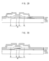
- FIG. 17 is a plan view illustrating a thin film transistor substrate according to an exemplary embodiment of the inventive concept.
- FIG. 18 is a cross-sectional view taken along line III-III' of FIG. 17 .
- a thin film transistor substrate 2100 includes a gate line GL, a data line DL crossing the gate line GL, a thin film transistor SW which is a switching element, and a pixel electrode PE.
- the thin film transistor SW may be electrically connected to the gate line GL and the data line DL.
- the pixel electrode PE may be electrically connected to the thin film transistor SW through a contact hole CNT.
- the gate line GL extends in a first direction.
- the gate line GL may have a single layer structure including copper (Cu), silver (Ag), chrome (Cr), molybdenum (Mo), aluminum (Al), titanium (Ti), manganese (Mn) or any mixture thereof.
- the gate line GL may have a multilayer structure having a plurality of layers of different materials.
- the gate line GL may include a copper layer and a titanium layer disposed on and/or under the copper layer.
- the gate line GL is electrically connected to a gate electrode GE of the thin film transistor SW.
- portions of the gate line GL may form the gate electrode GE.
- a gate insulation layer 2120 is formed on the gate line GL and the gate electrode GE.
- the gate insulation layer 2120 may include an inorganic material such as silicon oxide (SiOx) and/or silicon nitride (SiNx).
- the gate insulation layer 2120 can include silicon oxide (SiOx), and may have a thickness of about 500 ⁇ (500*10 -10 m).
- the gate insulation layer 2120 may include a plurality of layers of different materials.
- the active pattern AP includes an oxide semiconductor.
- the oxide semiconductor may include zinc oxide ("ZnO"), zinc tin oxide (“ZTO”), indium zinc oxide (“IZO”), indium oxide (“InO”), titanium oxide (“TiO”), indium gallium zinc oxide (“IGZO”), indium zinc tin oxide (“IZTO”) or the like. Any one or more of these materials is contemplated.
- the oxide semiconductor may include IGZO.
- a source metal pattern is formed on the active pattern AP.
- the source metal pattern may include the data line DL, a source electrode SE and a drain electrode DE.
- the data line DL is electrically connected to the source electrode SE.
- the source electrode SE may protrude from the data line DL in the first direction.
- the data line DL, the source electrode SE and the drain electrode DE may be disposed in a same layer.
- the first passivation layer 2130 may include an inorganic material such as silicon oxide (SiOx) and/or silicon nitride (SiNx).
- the first passivation layer 2130 may include a silicon oxide (SiOx), an aluminum oxide (AlOx), a gallium oxide (GaOx), a titanium oxide (TiOx), a tantalum oxide (TaOx), a manganese oxide (MnOx), a silicon oxynitride (SiON), an aluminum oxynitride (AlON) or a gallium oxynitride (GaON).
- the first passivation layer 2130 may be formed by using a plasma treatment process.
- the first passivation layer 2130 may include a first sub passivation layer 2131, a second sub passivation layer 2132, a third sub passivation layer 2133 and a fourth sub passivation layer 2134.
- the first sub passivation layer 2131, the second sub passivation layer 2132 and the third sub passivation layer 2133 may be formed by a plasma treatment process using an electric power less than 1.5kW.
- a silicon oxide (SiOx) first passivation layer 2130 is formed using a low electric power, H 2 SiOx may be generated.
- the quantity of hydrogen in first passivation layer 2130 layer may be increased.
- the first sub passivation layer 2131, the second sub passivation layer 2132 and the third sub passivation layer 2133 are formed using a relatively low electric power, deterioration of the active pattern and the source metal pattern may be minimized.
- oxygen may be provided to the active pattern AP, so that carriers may be increased in the active pattern AP.
- the first sub passivation layer 2131 contacts the active pattern AP.
- the first sub passivation layer 2131 may be formed using an electric power of more than 0.3kW and less than 0.5kW.
- the first sub passivation layer 2131 may be formed using an electric power of 0.4kW
- the second sub passivation layer 2132 is disposed on the first sub passivation layer 2131.
- the second sub passivation layer 2132 may be formed using an electric power of more than 0.6kW and less than 0.8kW.
- the second sub passivation layer 2132 may be formed using an electric power of 0.7kW.
- the third sub passivation layer 2133 is disposed on the second sub passivation layer 2132.
- the third sub passivation layer 2133 may be formed using an electric power of more than 0.9kW and less than 1.2kW.
- the third sub passivation layer 2133 may be formed using an electric power of 1.0kW.
- the fourth sub passivation layer 2134 may be formed using an electric power of more than 3.5kW and less than 4.5kW Preferably, the fourth sub passivation layer 2134 may be formed using an electric power of 4.0kW.
- the quantity of hydrogen contained in the first sub passivation layer 2131 is greater than the quantity of hydrogen contained in the second sub passivation layer 2132.
- the quantity of hydrogen contained in the second sub passivation layer 2132 is greater than the quantity of hydrogen contained in the third sub passivation layer 2133.
- the quantity of hydrogen contained in the third sub passivation layer 2133 is greater than the quantity of hydrogen contained in the fourth sub passivation layer 2134.
- the first sub passivation layer 2131, the second sub passivation layer 2132, the third sub passivation layer 2133 and the fourth sub passivation layer 2134 may each include the same material.
- a second passivation layer 2140 is formed on the first passivation layer 2130.
- the second passivation layer 2140 may include an inorganic material such as silicon oxide (SiOx) and/or silicon nitride (SiNx).
- the second passivation layer 2140 includes silicon oxide (SiOx), and may have a thickness of about 500 ⁇ (500*10 -10 m).
- the second passivation layer 2140 may include a plurality of layers of different materials.
- the second passivation layer 2140 may be formed using a plasma treatment process.
- the second passivation layer 2140 may be formed by plasma treatment using an electric power of more than 7.5kW and less than 8.5kW
- the second passivation layer 2140 may be formed using an electric power of 7.7kW.
- the quantity or density of hydrogen contained in the first passivation layer 2130 is less than the quantity or density of hydrogen contained in the second passivation layer 2140.
- An organic layer 2150 is formed on the second passivation layer 2140.
- the organic layer 2150 planarizes an upper surface of the thin film transistor substrate 2100 so that problems due to step height differences in the upper surfaces of underlying layers, such as disconnection of a signal line, may be prevented.
- the organic layer 2150 may be an insulation layer including an organic material.
- the organic layer 2150 may a color filter layer.
- the color filter layer may be a color filter layer having any color, such as a red color, a green color, a blue color or a white color.
- a pixel electrode PE is formed on the organic layer 2150.
- the pixel electrode PE may include a transparent conductive material, such as indium tin oxide (ITO) and/or indium zinc oxide (IZO).
- the pixel electrode PE may include titanium (Ti) and/or molybdenum titanium (MoTi).
- the pixel electrode PE may be electrically connected to the drain electrode DE.
- the pixel electrode PE may be electrically connected to the drain electrode DE through the contact hole CNT.
- FIGS. 19 to 22 are cross-sectional views illustrating a method of manufacturing the thin film transistor substrate of FIG. 18 .
- FIGS. 23A and 23B are graphs illustrating plasma treatment electric power usage in a method of manufacturing the thin film transistor substrate of FIG. 18 .
- a gate electrode GE, a gate insulation layer 2120, an active pattern AP, a source electrode SE and a drain electrode DE are formed on a base substrate 2110.
- a gate metal pattern including the gate electrode GE is formed on the base substrate 2110.
- the gate metal pattern may further include a gate line electrically connected with the gate electrode GE.
- a gate metal layer is patterned to form the gate line and the gate electrode GE, after the gate metal layer is formed on the base substrate 2110.
- the base substrate 2110 may include a glass substrate, a quartz substrate, a silicon substrate, a plastic substrate or the like.
- the gate metal layer may have a single layer structure including copper (Cu), silver (Ag), chrome (Cr), molybdenum (Mo), aluminum (Al), titanium (Ti), manganese (Mn) or any mixture thereof.
- the gate metal layer may have a multilayer structure having a plurality of layers including materials different each other.
- the gate metal layer may include a copper layer and a titanium layer disposed on and/or under the copper layer.
- a gate insulation layer 2120 is formed on the gate line GL and the gate electrode GE.
- the gate insulation layer 2120 may include an inorganic material such as silicon oxide (SiOx) and/or silicon nitride (SiNx).
- the gate insulation layer 2120 can include silicon oxide (SiOx).
- the gate insulation layer 2120 may include a plurality of layers of different materials.
- the active pattern AP includes an oxide semiconductor.
- the oxide semiconductor may include zinc oxide ("ZnO"), zinc tin oxide (“ZTO”), indium zinc oxide (“IZO”), indium oxide (“InO”), titanium oxide (“TiO”), indium gallium zinc oxide (“IGZO”), indium zinc tin oxide (“IZTO”) or the like. These may be used individually or in any combination.
- the oxide semiconductor may include IGZO.
- a source metal pattern is formed on the active pattern AP.
- the source metal pattern may include the data line DL, a source electrode SE and a drain electrode DE.
- the data line DL is electrically connected to the source electrode SE.
- the source electrode SE may protrude from the data line DL in the first direction.
- the data line DL, the source electrode SE and the drain electrode DE may be disposed in a same layer.
- a first passivation layer 2130 is formed on the source electrode SE and the drain electrode DE.
- the first passivation layer 2130 may include a first sub passivation layer 2131, a second sub passivation layer 2132, a third sub passivation layer 2133 and a fourth sub passivation layer 2134.
- the first sub passivation layer 2131, the second sub passivation layer 2132 and the third sub passivation layer 2133 may be formed by a plasma treatment process as above, using an electric power less than 1.5kW.
- the first passivation layer 2130 includes a silicon oxide (SiOx) and is formed by using a low electric power, H 2 SiOx may be generated.
- the quantity of hydrogen in first passivation layer 2130 layer may be increased.
- the first sub passivation layer 2131, the second sub passivation layer 2132 and the third sub passivation layer 2133 are formed using a relatively low electric power, deterioration of the active pattern AP and the source metal pattern may be minimized.
- oxygen may be provided to the active pattern AP, so that carriers may be increased in the active pattern AP.
- the first sub passivation layer 2131 contacts the active pattern AP.
- the first sub passivation layer 2131 may be formed using an electric power of more than 0.3kW and less than 0.5kW.
- the first sub passivation layer 2131 may be formed using an electric power of 0.4kW
- the second sub passivation layer 2132 is disposed on the first sub passivation layer 2131.
- the second sub passivation layer 2132 may be formed using an electric power of more than 0.6kW and less than 0.8kW.
- the second sub passivation layer 2132 may be formed using an electric power of 0.7kW.
- the third sub passivation layer 2133 is disposed on the second sub passivation layer 2132.
- the third sub passivation layer 2133 may be formed using an electric power of more than 0.9kW and less than 1.2kW. Preferably, the third sub passivation layer 2133 may be formed using an electric power of 1.0kW. As one example, the fourth sub passivation layer 2134 may be formed using an electric power of more than 3.5kW and less than 4.5kW Preferably, the fourth sub passivation layer 2134 may be formed using an electric power of 4.0kW.
- the quantity of hydrogen contained in the first sub passivation layer 2131 is greater than the quantity of hydrogen contained in the second sub passivation layer 2132.
- the quantity of hydrogen contained in the second sub passivation layer 2132 is greater than the quantity of hydrogen contained in the third sub passivation layer 2133.
- the quantity of hydrogen contained in the third sub passivation layer 2133 is greater than the quantity of hydrogen contained in the fourth sub passivation layer 2134.
- the first sub passivation layer 2131, the second sub passivation layer 2132, the third sub passivation layer 2133 and the fourth sub passivation layer 2134 may include the same material.
- a second passivation layer 2140 is formed on the first passivation layer 2130.
- the second passivation layer 2140 may be formed using a plasma treatment process.
- the second passivation layer 2140 may be formed using an electric power of more than 7.5kW and less than 8.5kW
- the second passivation layer 2140 may be formed using an electric power of 7.7kW.
- the quantity of hydrogen contained in the first passivation layer 2130 is less than the quantity of hydrogen contained in the second passivation layer 2140.
- the second passivation layer 2140 may include an inorganic material such as silicon oxide (SiOx) and/or silicon nitride (SiNx).
- the second passivation layer 2140 may include silicon oxide (SiOx), and may have a thickness of about 500 ⁇ (500*10 -10 m).
- the second passivation layer 2140 may include a plurality of layers of different materials.
- the first passivation layer 2130 may be formed using an electric power of D kW, E kW, A kW and B kW.
- the first passivation layer 2130 may include a first sub passivation layer 2131, a second sub passivation layer 2132, a third sub passivation layer 2133 and a fourth sub passivation layer 2134, as above.
- the first sub passivation layer 2131 may be formed using an electric power of D kW.
- the second sub passivation layer 2132 may be formed using an electric power of E kW which is higher than power level D.
- the third sub passivation layer 2133 may be formed using an electric power of A kW which is higher than power level E.
- power level A may be 1.0kW.
- the fourth sub passivation layer 2134 may be formed using an electric power of B kW which is higher than power level A.
- power level B kW may be 4.0kW. That is, the first passivation layer 2130 may be formed using an electric power of D kW, E kW, AkW and B kW during a first time t1.
- the second passivation layer 2140 may be formed using an electric power of C kW which is higher than B. That is, the second passivation layer 2140 may be formed using an electric power of C kW during a second time t2.
- the third time t3 may be more than 5 seconds and less than 20 seconds.
- the power level C may be 7.7kW.
- the first time t1 may be about twice the second time t2.
- an organic layer 2150 is formed over the second passivation layer 2140. Thereafter, a contact hole CNT is formed through the first passivation layer 2130, the second passivation layer 2140 and the organic layer 2150.
- the organic layer 2150 planarizes an upper surface of the thin film transistor substrate 2100 so that problems due to step differences in elevations of an underlying surface, such as disconnection of a signal line, may be prevented.
- the organic layer 2150 may be an insulation layer including an organic material.
- the organic layer 2150 may a color filter layer.
- the color filter layer may be a color filter layer having any color, such as a red color, a green color, a blue color or a white color.
- a pixel electrode PE may be electrically connected to the drain electrode DE.
- the pixel electrode PE may be electrically connected to the drain electrode DE through the contact hole CNT.
- a transparent conductive layer is formed on the organic layer 2150 and patterned to form a pixel electrode PE.
- the transparent conductive layer may include a transparent conductive material, such as indium tin oxide (ITO) and/or indium zinc oxide (IZO).
- ITO indium tin oxide
- IZO indium zinc oxide
- the pixel electrode PE may be electrically connected to the drain electrode DE through the contact hole CNT.
- first sub passivation layer 2131, the second sub passivation layer 2132 and the third sub passivation layer 2133 are formed by using a relatively low electric power, deterioration of the active pattern and the source metal pattern may be minimized.
- first sub passivation layer 2131, the second sub passivation layer 2132 and the third sub passivation layer 2133 include silicon oxide (SiOx) and are formed using a low electric power, H 2 SiOx may be generated.
- SiOx silicon oxide
- H 2 SiOx H 2 SiOx
- FIG. 24 is a plan view illustrating a thin film transistor substrate according to an exemplary embodiment of the inventive concept.
- FIG. 25 is a cross-sectional view taken along line IV-IV' of FIG. 24 .
- a thin film transistor substrate 3100 includes a gate line GL, a data line DL crossing the gate line GL, a thin film transistor SW which is a switching element, and a pixel electrode PE.
- the thin film transistor SW may be electrically connected to the gate line GL and the data line DL.
- the pixel electrode PE may be electrically connected to the thin film transistor SW through a contact hole CNT.
- the thin film transistor substrate 3100 according to the present exemplary embodiment is substantially the same as the thin film transistor substrate of FIGS. 1 and 2 except for a lower buffer layer BL1, and thus like reference numerals are used for like elements and repetitive explanation will be omitted.
- the lower buffer layer BL1 is formed on the gate insulation layer 3120.
- the lower buffer layer BL1 may include an inorganic material such as silicon oxide (SiOx) and/or silicon nitride (SiNx).
- the lower buffer layer BL1 may include a silicon oxide
- SiOx an aluminum oxide (AlOx), a gallium oxide (GaOx), a titanium oxide (TiOx), a tantalum oxide (TaOx), a manganese oxide (MnOx), a silicon oxynitride (SiON), an aluminum oxynitride (AlON) or a gallium oxynitride (GaON).
- the lower buffer layer BL1 may be formed using a plasma treatment process.
- the lower buffer layer BL 1 may be formed using an electric power of more than 0.5kW and less than 1.5kW.
- the lower buffer layer BL1 may be formed using an electric power of 1.0kW.
- the lower buffer layer includes silicon oxide (SiOx) and is formed by using a low electric power, H 2 SiOx may be generated.
- SiOx silicon oxide
- H 2 SiOx may be generated.
- the quantity of hydrogen in the lower buffer layer BL1 may be increased. Since the lower buffer layer BL1 is formed using a relatively low electric power, deterioration of the active pattern AP and the source metal pattern may be minimized.
- oxygen may be provided to the active pattern AP, so that carriers may be increased in the active pattern AP.
- the quantity of hydrogen contained in the lower buffer layer BL1 is greater than the quantity of hydrogen contained in the first passivation layer 3130.
- the active pattern AP includes an oxide semiconductor.
- the oxide semiconductor may include zinc oxide ("ZnO"), zinc tin oxide ("ZTO"), indium zinc oxide (“IZO”), indium oxide ("InO”), titanium oxide (“TiO”), indium gallium zinc oxide (“IGZO”), indium zinc tin oxide (“IZTO”) or the like. Any of these materials, or any combination thereof, may be used.
- the oxide semiconductor may include IGZO.
- a source metal pattern is formed on the active pattern AP.
- the source metal pattern may include the data line DL, a source electrode SE and a drain electrode DE.
- the data line DL is electrically connected to the source electrode SE.
- the source electrode SE may protrude from the data line DL in the first direction.
- the data line DL, the source electrode SE and the drain electrode DE may be disposed in a same layer.
- the buffer layer BL2 may include an inorganic material such as silicon oxide (SiOx) and/or silicon nitride (SiNx).
- the buffer layer BL2 may include a silicon oxide (SiOx), an aluminum oxide (AlOx), a gallium oxide (GaOx), a titanium oxide (TiOx), a tantalum oxide (TaOx), a manganese oxide (MnOx), a silicon oxynitride (SiON), an aluminum oxynitride (AlON) or a gallium oxynitride (GaON).
- the buffer layer BL2 may be formed by using a plasma treatment process.
- the buffer layer BL2 may be formed using an electric power of more than 0.5kW and less than 1.5kW.
- the buffer layer BL2 may be formed using an electric power of 1.0kW.
- the buffer layer includes silicon oxide (SiOx) and is formed by using a low electric power, H 2 SiOx may be generated.
- SiOx silicon oxide
- H 2 SiOx may be generated.
- the quantity of hydrogen in the buffer layer BL2 may be increased. Since the buffer layer BL2 is formed by using a relatively low electric power, deterioration of the active pattern AP and the source metal pattern may be minimized.
- oxygen may be provided to the active pattern AP, so that carrier numbers may be increased in the active pattern AP.
- a first passivation layer 3130 is formed on the buffer layer BL2.
- the first passivation layer 3130 may include an inorganic material such as silicon oxide (SiOx) and/or silicon nitride (SiNx).
- the first passivation layer 3130 can include silicon oxide (SiOx), and may have a thickness of about 500 ⁇ (500*10 -10 m).
- the first passivation layer 3130 may include a plurality of layers of different materials.
- the first passivation layer 3130 may be formed using a plasma treatment process. In this process, the first passivation layer 3130 may be formed using an electric power of more than 3.5kW and less than 4.5kW Preferably, the first passivation layer 3130 may be formed using an electric power of 4.0kW
- the quantity of hydrogen contained in the buffer layer BL2 is greater than the quantity of hydrogen contained in the first passivation layer 3130.
- a second passivation layer 3140 is formed on the first passivation layer 3130.
- the second passivation layer 3140 may include an inorganic material such as silicon oxide (SiOx) and/or silicon nitride (SiNx).
- the second passivation layer 3140 can include silicon oxide (SiOx), and may have a thickness of about 500 ⁇ (500*10 -10 m).
- the second passivation layer 3140 may include a plurality of layers of different materials.
- the second passivation layer 3140 may be formed using a plasma treatment process. In this process, the second passivation layer 3140 may be formed using an electric power of more than 7.5kW and less than 8.5kW Preferably, the second passivation layer 3140 may be formed using an electric power of 7.7kW.
- the quantity of hydrogen contained in the buffer layer BL2 is less than the quantity of hydrogen contained in the second passivation layer 3140.
- FIGS. 26 to 31 are cross-sectional views illustrating a method of manufacturing the thin film transistor substrate of FIG. 25 .
- a gate electrode GE, a gate insulation layer 3120 and a lower buffer layer BL1 are formed on a base substrate 3110.
- a gate metal pattern including the gate electrode GE is formed on the base substrate 3110.
- the gate metal pattern may further include a gate line electrically connected to the gate electrode GE.
- a gate metal layer is patterned to form the gate line and the gate electrode GE, after the gate metal layer is formed on the base substrate 3110.
- the base substrate 3110 may include a glass substrate, a quartz substrate, a silicon substrate, a plastic substrate or the like.
- the gate metal layer may have a single layer structure including copper (Cu), silver (Ag), chrome (Cr), molybdenum (Mo), aluminum (Al), titanium (Ti), manganese (Mn) or any mixture thereof.
- the gate metal layer may have a multilayer structure having a plurality of layers of different materials.
- the gate metal layer may include a copper layer and a titanium layer disposed on and/or under the copper layer.
- a gate insulation layer 3120 is formed on the gate line GL and the gate electrode GE.
- the gate insulation layer 3120 may include an inorganic material such as silicon oxide (SiOx) and/or silicon nitride (SiNx).
- the gate insulation layer 3120 may include silicon oxide (SiOx).
- the gate insulation layer 3120 may include a plurality of layers of different materials.
- the lower buffer layer BL1 is formed on the gate insulation layer 3120.
- the lower buffer layer BL1 may include an inorganic material such as silicon oxide (SiOx) and/or silicon nitride (SiNx).
- the lower buffer layer BL1 may include a silicon oxide (SiOx), an aluminum oxide (AlOx), a gallium oxide (GaOx), a titanium oxide (TiOx), a tantalum oxide (TaOx), a manganese oxide (MnOx), a silicon oxynitride (SiON), an aluminum oxynitride (AlON) or a gallium oxynitride (GaON).
- the lower buffer layer BL1 may be formed by using a plasma treatment process.
- the lower buffer layer BL1 may be formed using an electric power of more than 0.5kW and less than 1.5kW.
- the lower buffer layer BL1 may be formed using an electric power of 1.0kW.
- the lower buffer layer includes a silicon oxide (SiOx) and is formed by using a low electric power, H 2 SiOx may be generated.
- SiOx silicon oxide
- H 2 SiOx may be generated.
- the quantity of hydrogen in the lower buffer layer BL1 may be increased. Since the lower buffer layer BL1 is formed using a relatively low electric power, deterioration of the active pattern AP and the source metal pattern may be minimized.
- oxygen may be provided to the active pattern AP, so that carrier numbers may be increased in the active pattern AP.
- an active pattern AP, a source electrode SE and a drain electrode DE are formed on the lower buffer layer BL1.
- the active pattern AP includes an oxide semiconductor.
- the oxide semiconductor may include zinc oxide ("ZnO"), zinc tin oxide ("ZTO”), indium zinc oxide (“IZO”), indium oxide (“InO”), titanium oxide (“TiO”), indium gallium zinc oxide (“IGZO”), indium zinc tin oxide
- the oxide semiconductor may include IGZO.
- a source metal pattern is formed on the active pattern AP.
- the source metal pattern may include the data line DL, a source electrode SE and a drain electrode DE.
- the data line DL is electrically connected to the source electrode SE.
- the source electrode SE may protrude from the data line DL in the first direction.
- the data line DL, the source electrode SE and the drain electrode DE may be disposed in a same layer.
- a buffer layer BL2 is formed on the source electrode SE and the drain electrode DE.
- the buffer layer BL2 may be formed by using a plasma treatment process.
- the buffer layer BL2 may be formed using an electric power of more than 0.5kW and less than 1.5kW.
- the buffer layer BL2 may be formed using an electric power of 1.0kW.
- the buffer layer includes silicon oxide (SiOx) and is formed using a low electric power, H 2 SiOx may be generated.
- SiOx silicon oxide
- H 2 SiOx may be generated.
- the quantity of hydrogen in the buffer layer BL2 may be increased. Since the buffer layer BL2 is formed using a relatively low electric power, deterioration of the active pattern AP and the source metal pattern may be minimized.
- oxygen may be provided to the active pattern AP, so that carrier amounts may be increased in the active pattern AP.
- the buffer layer BL2 may include an inorganic material such as silicon oxide (SiOx) and/or silicon nitride (SiNx).
- the buffer layer BL2 may include a silicon oxide (SiOx), an aluminum oxide (AlOx), a gallium oxide (GaOx), a titanium oxide (TiOx), a tantalum oxide (TaOx), a manganese oxide (MnOx), a silicon oxynitride (SiON), an aluminum oxynitride (AlON) or a gallium oxynitride (GaON).
- a first passivation layer 3130 is formed on the buffer layer BL2.
- the first passivation layer 3130 may be formed using a plasma treatment process. During this process, the first passivation layer 3130 may be formed using an electric power of more than 3.5kW and less than 4.5kW Preferably, the first passivation layer 3130 may be formed using an electric power of 4.0kW The quantity of hydrogen contained in the buffer layer BL2 is greater than the quantity of hydrogen contained in the first passivation layer 3130.
- the first passivation layer 3130 may include an inorganic material such as silicon oxide (SiOx) and/or silicon nitride (SiNx).
- the first passivation layer 3130 may include silicon oxide (SiOx), and may have a thickness of about 500 ⁇ (500*10 -10 m).
- the first passivation layer 3130 may include a plurality of layers of different materials.
- a second passivation layer 3140 is formed on the first passivation layer 3130.
- the second passivation layer 3140 may be formed using a plasma treatment process.
- the second passivation layer 3140 may be formed by using an electric power of more than 7.5kW and less than 8.5kW
- the second passivation layer 3140 may be formed by using an electric power of 7.7kW.
- the quantity of hydrogen contained in the buffer layer BL2 is less than quantity of hydrogen contained in the second passivation layer 3140.
- the second passivation layer 3140 may include an inorganic material such as silicon oxide (SiOx) and/or silicon nitride (SiNx).
- the second passivation layer 3140 may include silicon oxide (SiOx), and may have a thickness of about 500 ⁇ (500*10 -10 m).
- the second passivation layer 3140 may include a plurality of layers having different materials from each other.
- an organic layer 3150 is formed on the base substrate 3110 on which the second passivation layer 3140 is formed. Thereafter, a contact hole CNT is formed through the buffer layer BL2, the first passivation layer 3130, the second passivation layer 3140 and the organic layer 3150.
- the organic layer 3150 planarizes an upper surface of the thin film transistor substrate 3100 so that problems due to step discontinuities in underlying layers, such as disconnection of a signal line, may be prevented.
- the organic layer 3150 may be an insulation layer including an organic material.
- the organic layer 3150 may a color filter layer.
- the color filter layer may be a color filter layer having any color, such as a red color, a green color, a blue color or a white color.
- a pixel electrode PE may be electrically connected to the drain electrode DE.
- the pixel electrode PE may be electrically connected to the drain electrode DE through the contact hole CNT.
- a transparent conductive layer is formed on the organic layer 3150 and patterned to form a pixel electrode PE.
- the transparent conductive layer may include a transparent conductive material, such as indium tin oxide (ITO) and indium zinc oxide (IZO).
- ITO indium tin oxide
- IZO indium zinc oxide
- the pixel electrode PE may be electrically connected to the drain electrode DE through the contact hole CNT.
- the buffer layer BL2 is formed using a relatively low electric power as above, deterioration of the active pattern and the source metal pattern may be minimized.
- the buffer layer BL2 includes silicon oxide (SiOx) and is formed using a low electric power, H 2 SiOx may be generated.
- the quantity of hydrogen in the buffer layer BL2 may be increased. Accordingly, oxygen may be provided to the active pattern AP, so that carriers may be increased in the active pattern AP.
- FIG. 32 is a plan view illustrating a thin film transistor substrate according to an exemplary embodiment of the inventive concept.
- FIG. 33 is a cross-sectional view taken along line V-V' of FIG. 32 .
- a thin film transistor substrate 4100 includes a gate line GL, a data line DL crossing the gate line GL, a thin film transistor SW which is a switching element, and a pixel electrode PE.
- the thin film transistor SW may be electrically connected to the gate line GL and the data line DL.
- the pixel electrode PE may be electrically connected to the thin film transistor SW through a contact hole CNT.
- the thin film transistor substrate 4100 according to the present exemplary embodiment is substantially the same as the thin film transistor substrate of FIGS. 9 and 10 except for a lower buffer layer BL1, and thus like reference numerals are used for like elements and repetitive explanation will be omitted.
- the lower buffer layer BL1 is formed on the gate insulation layer 4120.
- the lower buffer layer BL1 may include an inorganic material such as silicon oxide (SiOx) and/or silicon nitride (SiNx).
- the lower buffer layer BL1 may include a silicon oxide (SiOx), an aluminum oxide (AlOx), a gallium oxide (GaOx), a titanium oxide (TiOx), a tantalum oxide (TaOx), a manganese oxide (MnOx), a silicon oxynitride (SiON), an aluminum oxynitride (AlON) or a gallium oxynitride (GaON).
- the lower buffer layer BL1 may be formed by a plasma treatment process.
- the lower buffer layer BL1 may be formed by plasma treatment at an electric power of more than 0.5kW and less than 1.5kW.
- the lower buffer layer BL1 may be formed using an electric power of 1.0kW.
- the lower buffer layer BL1 includes silicon oxide (SiOx) and is formed by using a low electric power, H 2 SiOx may be generated.
- SiOx silicon oxide
- H 2 SiOx may be generated.
- the quantity of hydrogen in the lower buffer layer BL1 may be increased. Since the lower buffer layer BL1 is formed using a relatively low electric power, deterioration of the active pattern AP and the source metal pattern may be minimized.
- oxygen may be provided to the active pattern AP, so that carriers may be increased in the active pattern AP.
- the active pattern AP includes an oxide semiconductor.
- the oxide semiconductor may include zinc oxide ("ZnO"), zinc tin oxide (“ZTO”), indium zinc oxide (“IZO”), indium oxide (“InO”), titanium oxide (“TiO”), indium gallium zinc oxide (“IGZO”), indium zinc tin oxide (“IZTO”) or the like. These may be used each alone or in a combination thereof.
- the oxide semiconductor may include IGZO.
- a source metal pattern is formed on the active pattern AP.
- the source metal pattern may include the data line DL, a source electrode SE and a drain electrode DE.
- the data line DL is electrically connected to the source electrode SE.
- the source electrode SE may protrude from the data line DL in the first direction.
- the data line DL, the source electrode SE and the drain electrode DE may be disposed in a same layer.
- the buffer layer BL2 may include an inorganic material such as silicon oxide (SiOx) and/or silicon nitride (SiNx).
- the buffer layer BL2 may include a silicon oxide (SiOx), an aluminum oxide (AlOx), a gallium oxide (GaOx), a titanium oxide (TiOx), a tantalum oxide (TaOx), a manganese oxide (MnOx), a silicon oxynitride (SiON), an aluminum oxynitride (AlON) or a gallium oxynitride (GaON).
- the buffer layer BL2 may be formed by using a plasma treatment process.
- the buffer layer BL2 may be formed by plasma treatment using an electric power of more than 0.5kW and less than 1.5kW.
- the buffer layer BL2 may be formed using an electric power of 1.0kW.
- the buffer layer BL2 includes silicon oxide (SiOx) and is formed using a low electric power, H 2 SiOx may be generated.
- SiOx silicon oxide
- H 2 SiOx may be generated.
- the quantity of hydrogen in the buffer layer BL2 may be increased. Since the buffer layer BL2 is formed using a relatively low electric power, deterioration of the active pattern AP and the source metal pattern may be minimized.
- oxygen may be provided to the active pattern AP, so that carriers may be increased in the active pattern AP.
- the buffer layer BL2 may include a first sub buffer layer SBL1, a second sub buffer layer SBL2 and a third sub buffer layer SBL3.
- the first sub buffer layer SBL1 contacts the active pattern AP.
- the first sub buffer layer SBL1 may be formed by plasma treatment using an electric power of more than 0.3kW and less than 0.5kW.
- the first sub buffer layer SBL1 may be formed using an electric power of 0.4kW
- the second sub buffer layer SBL2 is disposed on the first sub buffer layer SBL1.
- the second sub buffer layer SBL2 may be formed by plasma treatment using an electric power of more than 0.6kW and less than 0.8kW.
- the second sub buffer layer SBL2 may be formed using an electric power of 0.7kW.
- the third sub buffer layer SBL3 contacts a first passivation layer 1130.
- the third sub buffer layer SBL3 may be formed by plasma treatment as well, using an electric power of more than 0.9kW and less than 1.2kW.
- the third sub buffer layer SBL3 may be formed using an electric power of 1.0kW.
- the quantity of hydrogen contained in the first sub buffer layer SBL1 is greater than the quantity of hydrogen contained in the second sub buffer layer SBL2.
- the quantity of hydrogen contained in the second sub buffer layer SBL2 is greater than the quantity of hydrogen contained in the third sub buffer layer SBL3.
- the first sub buffer layer SBL1, the second sub buffer layer SBL2 and the third sub buffer layer SBL3 may each include the same material.
- a first passivation layer 4130 is formed on the third sub buffer layer SBL3.
- the first passivation layer 4130 may include an inorganic material such as silicon oxide (SiOx) and/or silicon nitride (SiNx).
- the first passivation layer 4130 can include silicon oxide (SiOx), and may have a thickness of about 500 ⁇ (500*10 -10 m).
- the first passivation layer 4130 may include a plurality of layers having different materials from each other.
- the first passivation layer 4130 may be formed using a plasma treatment process.
- the first passivation layer 4130 may be formed by plasma treatment using an electric power of more than 3.5kW and less than 4.5kW
- the first passivation layer 4130 may be formed using an electric power of 4.0kW
- the quantity of hydrogen contained in the buffer layer BL2 is greater than the quantity of hydrogen contained in the first passivation layer 4130.
- a second passivation layer 4140 is formed on the first passivation layer 4130.
- the second passivation layer 4140 may include an inorganic material such as silicon oxide (SiOx) and/or silicon nitride (SiNx).
- the second passivation layer 4140 can include silicon oxide (SiOx), and may have a thickness of about 500 ⁇ (500*10 -10 m).
- the second passivation layer 4140 may include a plurality of layers having different materials from each other.
- the second passivation layer 4140 may be formed using a plasma treatment process.
- the second passivation layer 4140 may be formed by plasma treatment using an electric power of more than 7.5kW and less than 8.5kW
- the second passivation layer 4140 may be formed using an electric power of 7.7kW.
- the quantity of hydrogen contained in the buffer layer BL2 is less than the quantity of hydrogen contained in the second passivation layer 4140.
- FIGS. 34 to 39 are cross-sectional views illustrating a method of manufacturing the thin film transistor substrate of FIG. 33 .
- a gate electrode GE, a gate insulation layer 4120 and a lower buffer layer BL1 are formed on a base substrate 4110.
- a gate metal pattern is formed on the base substrate 4110 and patterned to form the gate line and the gate electrode GE.
- the gate line is electrically connected to the gate electrode GE.
- Examples of the base substrate 4110 may include a glass substrate, a quartz substrate, a silicon substrate, a plastic substrate or the like.
- the gate metal layer may have a single layer structure including copper (Cu), silver (Ag), chrome (Cr), molybdenum (Mo), aluminum (Al), titanium (Ti), manganese (Mn) or any mixture thereof.
- the gate metal layer may have a multilayer structure having a plurality of layers of materials that are different from each other.
- the gate metal layer may include a copper layer and a titanium layer disposed on and/or under the copper layer.
- a gate insulation layer 4120 is formed on the gate line GL and the gate electrode GE.
- the gate insulation layer 4120 may include an inorganic material such as silicon oxide (SiOx) and/or silicon nitride (SiNx).
- the gate insulation layer 4120 includes silicon oxide (SiOx).
- the gate insulation layer 4120 may include a plurality of layers having different materials from each other.
- the lower buffer layer BL1 is formed on the gate insulation layer 4120.
- the lower buffer layer BL1 may include an inorganic material such as silicon oxide (SiOx) and/or silicon nitride (SiNx).
- the lower buffer layer BL1 may include a silicon oxide (SiOx), an aluminum oxide (AlOx), a gallium oxide (GaOx), a titanium oxide (TiOx), a tantalum oxide (TaOx), a manganese oxide (MnOx), a silicon oxynitride (SiON), an aluminum oxynitride (AlON) or a gallium oxynitride (GaON).
- the lower buffer layer BL1 may be formed by using a plasma treatment process.
- the lower buffer layer BL1 may be formed by plasma treatment using an electric power of more than 0.5kW and less than 1.5kW.
- the lower buffer layer BL1 may be formed using an electric power of 1.0kW.
- the lower buffer layer BL1 includes silicon oxide (SiOx) and is formed by using a low electric power, H 2 SiOx may be generated.
- SiOx silicon oxide
- H 2 SiOx may be generated.
- the quantity of hydrogen in the lower buffer layer BL1 may be increased. Since the lower buffer layer BL1 is formed using a relatively low electric power, deterioration of the active pattern AP and the source metal pattern may be minimized.
- oxygen may be provided to the active pattern AP, so that carriers may be increased in the active pattern AP.
- an active pattern AP, a source electrode SE and a drain electrode DE are formed on the lower buffer layer BL1.
- the active pattern AP includes an oxide semiconductor.
- the oxide semiconductor may include zinc oxide ("ZnO"), zinc tin oxide (“ZTO”), indium zinc oxide (“IZO”), indium oxide (“InO”), titanium oxide (“TiO”), indium gallium zinc oxide (“IGZO”), indium zinc tin oxide (“IZTO”) or the like. These may be used each alone or in any combination.
- the oxide semiconductor may include IGZO.
- a source metal pattern is formed on the active pattern AP.
- the source metal pattern may include the data line DL, a source electrode SE and a drain electrode DE.
- the data line DL is electrically connected to the source electrode SE.
- the source electrode SE may protrude from the data line DL in the first direction.
- the data line DL, the source electrode SE and the drain electrode DE may be disposed in a same layer.
- a buffer layer BL2 is formed on the source electrode SE and the drain electrode DE.
- the buffer layer BL2 may include a first sub buffer layer SBL1, a second sub buffer layer SBL2 and a third sub buffer layer SBL3.
- the buffer layer BL2 may be formed by using a plasma treatment process.
- the buffer layer BL2 may be formed by plasma treatment using an electric power of less than 1.5kW.
- the buffer layer BL2 includes silicon oxide (SiOx) and is formed using a low electric power, H 2 SiOx may be generated.
- the quantity of hydrogen in the buffer layer BL2 may be increased. Since the buffer layer BL2 is formed using a relatively low electric power, deterioration of the active pattern AP and the source metal pattern may be minimized.
- oxygen may be provided to the active pattern AP, so that carriers may be increased in the active pattern AP.
- the buffer layer BL2 may include a first sub buffer layer SBL1, a second sub buffer layer SBL2 and a third sub buffer layer SBL3.
- the first sub buffer layer SBL1 contacts the active pattern AP.
- the first sub buffer layer SBL1 may be formed by plasma treatment using an electric power of more than 0.3kW and less than 0.5kW.
- the first sub buffer layer SBL1 may be formed using an electric power of 0.4kW
- the second sub buffer layer SBL2 is disposed on the first sub buffer layer SBL1.
- the second sub buffer layer SBL2 may be formed by plasma treatment using an electric power of more than 0.6kW and less than 0.8kW.
- the second sub buffer layer SBL2 may be formed using an electric power of 0.7kW.
- the third sub buffer layer SBL3 contacts a first passivation layer 1130.
- the third sub buffer layer SBL3 may be formed by plasma treatment using an electric power of more than 0.9kW and less than 1.2kW.
- the third sub buffer layer SBL3 may be formed using an electric power of 1.0kW.
- the quantity of hydrogen contained in the first sub buffer layer SBL1 is greater than the quantity of hydrogen contained in the second sub buffer layer SBL2.
- the quantity of hydrogen contained in the second sub buffer layer SBL2 is greater than the quantity of hydrogen contained in the third sub buffer layer SBL3.
- the first sub buffer layer SBL1, the second sub buffer layer SBL2 and the third sub buffer layer SBL3 may include the same material.
- the buffer layer BL2 may include an inorganic material such as silicon oxide (SiOx) and/or silicon nitride (SiNx).
- the buffer layer BL2 may include a silicon oxide (SiOx), an aluminum oxide (AlOx), a gallium oxide (GaOx), a titanium oxide (TiOx), a tantalum oxide (TaOx), a manganese oxide (MnOx), a silicon oxynitride (SiON), an aluminum oxynitride (AlON) or a gallium oxynitride (GaON).
- a first passivation layer 4130 is formed on the buffer layer BL2.
- the first passivation layer 4130 may be formed using a plasma treatment process. In this process, the first passivation layer 4130 may be formed using an electric power of more than 3.5kW and less than 4.5kW Preferably, the first passivation layer 4130 may be formed using an electric power of 4.0kW.
- the quantity of hydrogen contained in the buffer layer BL2 is greater than the quantity of hydrogen contained in the first passivation layer 4130.
- the first passivation layer 4130 may include an inorganic material such as silicon oxide (SiOx) and/or silicon nitride (SiNx).
- the first passivation layer 4130 can include silicon oxide (SiOx), and may have a thickness of about 500 ⁇ (500*10 -10 m).
- the first passivation layer 4130 may include a plurality of layers having different materials from each other.
- a second passivation layer 4140 is formed on the first passivation layer 4130.
- the second passivation layer 4140 may be formed using a plasma treatment process.
- the second passivation layer 4140 may be formed by plasma treatment using an electric power of more than 7.5kW and less than 8.5kW
- the second passivation layer 4140 may be formed using an electric power of 7.7kW.
- the quantity of hydrogen contained in the buffer layer BL2 is less than the quantity of hydrogen contained in the second passivation layer 4140.
- the second passivation layer 4140 may include an inorganic material such as silicon oxide (SiOx) and/or silicon nitride (SiNx).
- the second passivation layer 4140 can include silicon oxide (SiOx), and may have a thickness of about 500 ⁇ (500*10 -10 m).
- the second passivation layer 4140 may include a plurality of layers having different materials from each other.
- an organic layer 4150 is formed on the second passivation layer 4140. Thereafter, a contact hole CNT is formed through the buffer layer BL2, the first passivation layer 4130, the second passivation layer 4140 and the organic layer 4150.
- the organic layer 4150 planarizes an upper surface of the thin film transistor substrate 4100 so that problems due to step discontinuities in underlying layers, such as disconnection of a signal line, may be prevented.
- the organic layer 4150 may be an insulation layer including an organic material.
- the organic layer 4150 may a color filter layer.
- the color filter layer may be a color filter layer having any color, such as a red color, a green color, a blue color or a white color.
- a pixel electrode PE may be electrically connected to the drain electrode DE.
- the pixel electrode PE may be electrically connected to the drain electrode DE through the contact hole CNT.
- a transparent conductive layer is formed on the organic layer 4150 and patterned to form a pixel electrode PE.
- the transparent conductive layer may include a transparent conductive material, such as indium tin oxide (ITO) and indium zinc oxide (IZO).
- ITO indium tin oxide
- IZO indium zinc oxide
- the pixel electrode PE may be electrically connected to the drain electrode DE through the contact hole CNT.
- the buffer layer BL2 is formed using a relatively low electric power, deterioration of the active pattern AP and the source metal pattern may be minimized.
- the buffer layer BL2 includes silicon oxide (SiOx) and is formed using a low electric power, H 2 SiOx may be generated.
- the quantity of hydrogen in the buffer layer BL2 may be increased. Accordingly, oxygen may be provided to the active pattern AP, so that carriers may be increased in the active pattern AP.
- FIG. 40 is a plan view illustrating a thin film transistor substrate according to an exemplary embodiment of the inventive concept.
- FIG. 41 is a cross-sectional view taken along line VI-VI' of FIG. 40 .
- a thin film transistor substrate 5100 includes a gate line GL, a data line DL crossing the gate line GL, a thin film transistor SW which is a switching element, and a pixel electrode PE.
- the thin film transistor SW may be electrically connected to the gate line GL and the data line DL.
- the pixel electrode PE may be electrically connected to the thin film transistor SW through a contact hole CNT.
- the thin film transistor substrate 5100 according to the present exemplary embodiment is substantially the same as the thin film transistor substrate of FIGS. 17 and 18 except for a lower buffer layer BL, and thus like reference numerals are used for like elements and repetitive explanation will be omitted.
- the lower buffer layer BL is formed on the gate insulation layer 5120.
- the lower buffer layer BL may include an inorganic material such as silicon oxide (SiOx) and/or silicon nitride (SiNx).
- the lower buffer layer BL may include a silicon oxide (SiOx), an aluminum oxide (AlOx), a gallium oxide (GaOx), a titanium oxide (TiOx), a tantalum oxide (TaOx), a manganese oxide (MnOx), a silicon oxynitride (SiON), an aluminum oxynitride (AlON) or a gallium oxynitride (GaON).
- the lower buffer layer BL may be formed using a plasma treatment process.
- the lower buffer layer BL may be formed by plasma treatment using an electric power of more than 0.5kW and less than 1.5kW.
- the lower buffer layer BL may be formed using an electric power of 1.0kW.
- the lower buffer layer BL includes silicon oxide (SiOx) is formed using a low electric power, H 2 SiOx may be generated.
- SiOx silicon oxide
- H 2 SiOx may be generated.
- the quantity of hydrogen in the lower buffer layer BL may be increased. Since the lower buffer layer BL is formed using a relatively low electric power, deterioration of the active pattern AP and the source metal pattern may be minimized.
- oxygen may be provided to the active pattern AP, so that carriers may be increased in the active pattern AP.
- the active pattern AP includes an oxide semiconductor.
- the oxide semiconductor may include zinc oxide ("ZnO"), zinc tin oxide (“ZTO”), indium zinc oxide (“IZO”), indium oxide (“InO”), titanium oxide (“TiO”), indium gallium zinc oxide (“IGZO”), indium zinc tin oxide (“IZTO”) or the like. These may be used alone or in any combination.
- the oxide semiconductor may include IGZO.
- a source metal pattern is formed on the active pattern AP.
- the source metal pattern may include the data line DL, a source electrode SE and a drain electrode DE.
- the data line DL is electrically connected to the source electrode SE.
- the source electrode SE may protrude from the data line DL in the first direction.
- the data line DL, the source electrode SE and the drain electrode DE may be disposed in a same layer.
- the first passivation layer 5130 may include an inorganic material such as silicon oxide (SiOx) and/or silicon nitride (SiNx).
- the first passivation layer 5130 may include a silicon oxide (SiOx), an aluminum oxide (AlOx), a gallium oxide (GaOx), a titanium oxide (TiOx), a tantalum oxide (TaOx), a manganese oxide (MnOx), a silicon oxynitride (SiON), an aluminum oxynitride (AlON) or a gallium oxynitride (GaON).
- the first passivation layer 5130 may be formed using a plasma treatment process.
- the first passivation layer 5130 may include a first sub passivation layer 5131, a second sub passivation layer 5132, a third sub passivation layer 5133 and a fourth sub passivation layer 5134.
- the first sub passivation layer 5131, the second sub passivation layer 5132 and the third sub passivation layer 5133 may each be formed by plasma treatment using an electric power less than 1.5kW.
- the first passivation layer 5130 includes silicon oxide (SiOx) and is formed using a low electric power, H 2 SiOx may be generated.
- the quantity of hydrogen in first passivation layer 2130 layer may be increased.
- the first sub passivation layer 2131, the second sub passivation layer 2132 and the third sub passivation layer 2133 are formed using one or more relatively low electric power levels, deterioration of the active pattern AP and the source metal pattern may be minimized.
- oxygen may be provided to the active pattern AP, so that carriers may be increased in the active pattern AP.
- the first sub passivation layer 5131 contacts the active pattern AP.
- the first sub passivation layer 5131 may be formed using an electric power of more than 0.3kW and less than 0.5kW.
- the first sub passivation layer 5131 may be formed using an electric power of 0.4kW.
- the second sub passivation layer 5132 is disposed on the first sub passivation layer 5131.
- the second sub passivation layer 5132 may be formed using an electric power of more than 0.6kW and less than 0.8kW.
- the second sub passivation layer 5132 may be formed using an electric power of 0.7kW.
- the third sub passivation layer 5133 is disposed on the second sub passivation layer 5132.
- the third sub passivation layer 5133 may be formed using an electric power of more than 0.9kW and less than 1.2kW. Preferably, the third sub passivation layer 5133 may be formed using an electric power of 1.0kW.
- the fourth sub passivation layer 5134 is formed on the third sub passivation layer 5133 and may be formed using an electric power of more than 3.5kW and less than 4.5kW Preferably, the fourth sub passivation layer 5134 may be formed by using an electric power of 4.0kW
- the quantity of hydrogen contained in the first sub passivation layer 5131 is greater than the quantity of hydrogen contained in the second sub passivation layer 5132.
- the quantity of hydrogen contained in the second sub passivation layer 5132 is greater than the quantity of hydrogen contained in the third sub passivation layer 5133.
- the quantity of hydrogen contained in the third sub passivation layer 5133 is greater than the quantity of hydrogen contained in the fourth sub passivation layer 5134.
- the first sub passivation layer 5131, the second sub passivation layer 5132, the third sub passivation layer 5133 and the fourth sub passivation layer 5134 may all include the same material.
- a second passivation layer 5140 is formed on the first passivation layer 5130.
- the second passivation layer 5140 may include an inorganic material such as silicon oxide (SiOx) and/or silicon nitride (SiNx).
- the second passivation layer 5140 may include silicon oxide (SiOx), and may have a thickness of about 500 ⁇ (500*10 -10 m).
- the second passivation layer 5140 may include a plurality of layers of different materials.
- the second passivation layer 5140 may be formed using a plasma treatment process.
- the second passivation layer 5140 may be formed by plasma treatment using an electric power of more than 7.5kW and less than 8.5kW.
- the second passivation layer 5140 may be formed using an electric power of 7.7kW.
- the quantity of hydrogen contained in the first passivation layer 5130 is less than the quantity of hydrogen contained in the second passivation layer 5140.
- FIGS. 42 to 46 are cross-sectional views illustrating a method of manufacturing the thin film transistor substrate of FIG. 41 .
- a gate electrode GE, a gate insulation layer 5120 and a lower buffer layer BL are formed on a base substrate 5110.
- a gate metal layer is formed on the base substrate 5110 and patterned to form the gate line and the gate electrode GE.
- Examples of the base substrate 5110 may include a glass substrate, a quartz substrate, a silicon substrate, a plastic substrate or the like.
- the gate metal layer may have a single layer structure including copper (Cu), silver (Ag), chrome (Cr), molybdenum (Mo), aluminum (Al), titanium (Ti), manganese (Mn) or any mixture thereof.
- the gate metal layer may have a multilayer structure having a plurality of layers of materials different from each other.
- the gate metal layer may include a copper layer and a titanium layer disposed on and/or under the copper layer.
- a gate insulation layer 5120 is formed on the gate line GL and the gate electrode GE.
- the gate insulation layer 5120 may include an inorganic material such as silicon oxide (SiOx) and/or silicon nitride (SiNx).
- the gate insulation layer 5120 may include silicon oxide (SiOx).
- the gate insulation layer 5120 may include a plurality of layers of different materials.
- the lower buffer layer BL is formed on the gate insulation layer 5120.
- the lower buffer layer BL may include an inorganic material such as silicon oxide (SiOx) and/or silicon nitride (SiNx).
- the lower buffer layer BL may include a silicon oxide (SiOx), an aluminum oxide (AlOx), a gallium oxide (GaOx), a titanium oxide (TiOx), a tantalum oxide (TaOx), a manganese oxide (MnOx), a silicon oxynitride (SiON), an aluminum oxynitride (AlON) or a gallium oxynitride (GaON).
- the lower buffer layer BL may be formed using a plasma treatment process.
- the lower buffer layer BL may be formed by plasma treatment using an electric power of more than 0.5kW and less than 1.5kW.
- the lower buffer layer BL may be formed using an electric power of 1.0kW.
- the lower buffer layer includes silicon oxide (SiOx) and is formed using a low electric power, H 2 SiOx may be generated.
- SiOx silicon oxide
- H 2 SiOx may be generated.
- the quantity of hydrogen in the lower buffer layer BL may be increased. Since the lower buffer layer BL is formed using a relatively low electric power, deterioration of the active pattern AP and the source metal pattern may be minimized.
- oxygen may be provided to the active pattern AP, so that carriers may be increased in the active pattern AP.
- an active pattern AP, a source electrode SE and a drain electrode DE are formed on the lower buffer layer BL.
- the active pattern AP includes an oxide semiconductor.
- the oxide semiconductor may include zinc oxide ("ZnO"), zinc tin oxide ("ZTO"), indium zinc oxide (“IZO”), indium oxide ("InO”), titanium oxide (“TiO”), indium gallium zinc oxide (“IGZO”), indium zinc tin oxide (“IZTO”) or the like. Any single one of these materials, or any combination, may be used.
- the oxide semiconductor may include IGZO.
- a source metal pattern is formed on the active pattern AP.
- the source metal pattern may include the data line DL, a source electrode SE and a drain electrode DE.
- the data line DL is electrically connected to the source electrode SE.
- the source electrode SE may protrude from the data line DL in the first direction.
- the data line DL, the source electrode SE and the drain electrode DE may be disposed in a same layer.
- a first passivation layer 5130 is formed on the source electrode SE and the drain electrode DE.
- the first passivation layer 5130 may include a first sub passivation layer 5131, a second sub passivation layer 5132, a third sub passivation layer 5133 and a fourth sub passivation layer 5134.
- the first sub passivation layer 5131, the second sub passivation layer 5132 and the third sub passivation layer 5133 may each be formed by plasma treatment using an electric power less than 1.5kW.
- the first passivation layer 5130 includes silicon oxide (SiOx) and is formed using a low electric power, H 2 SiOx may be generated.
- the quantity of hydrogen in first passivation layer 5130 layer may be increased.
- the first sub passivation layer 5131, the second sub passivation layer 5132 and the third sub passivation layer 5133 are formed using a relatively low electric power, deterioration of the active pattern AP and the source metal pattern may be minimized.
- oxygen may be provided to the active pattern AP, so that carriers may be increased in the active pattern AP.
- the first sub passivation layer 5131 contacts the active pattern AP.
- the first sub passivation layer 5131 may be formed using an electric power of more than 0.3kW and less than 0.5kW.
- the first sub passivation layer 5131 may be formed using an electric power of 0.4kW.
- the second sub passivation layer 5132 is disposed on the first sub passivation layer 5131.
- the second sub passivation layer 5132 may be formed using an electric power of more than 0.6kW and less than 0.8kW.
- the second sub passivation layer 5132 may be formed using an electric power of 0.7kW.
- the third sub passivation layer 5133 is disposed on the second sub passivation layer 5132 and may be formed using an electric power of more than 0.9kW and less than 1.2kW.
- the third sub passivation layer 5133 may be formed using an electric power of 1.0kW.
- the fourth sub passivation layer 5134 may be disposed on the third sub passivation layer 5133 and formed using an electric power of more than 3.5kW and less than 4.5kW.
- the fourth sub passivation layer 5134 may be formed using an electric power of 4.0kW.
- the quantity of hydrogen contained in the first sub passivation layer 5131 is greater than the quantity of hydrogen contained in the second sub passivation layer 5132.
- the quantity of hydrogen contained in the second sub passivation layer 5132 is greater than the quantity of hydrogen contained in the third sub passivation layer 5133.
- the quantity of hydrogen contained in the third sub passivation layer 5133 is greater than the quantity of hydrogen contained in the fourth sub passivation layer 5134.
- the first sub passivation layer 5131, the second sub passivation layer 5132, the third sub passivation layer 5133 and the fourth sub passivation layer 5134 may all include the same material.
- a second passivation layer 5140 is formed on the first passivation layer 5130.
- the second passivation layer 5140 may be formed using a plasma treatment process.
- the second passivation layer 5140 may be formed by plasma treatment using an electric power of more than 7.5kW and less than 8.5kW.
- the second passivation layer 5140 may be formed using an electric power of 7.7kW.
- the quantity of hydrogen contained in the first passivation layer 5130 is less than the quantity of hydrogen contained in the second passivation layer 5140.
- the second passivation layer 5140 may include an inorganic material such as silicon oxide (SiOx) and/or silicon nitride (SiNx).
- the second passivation layer 5140 includes silicon oxide (SiOx), and may have a thickness of about 500 ⁇ (500*10 -10 m).
- the second passivation layer 5140 may include a plurality of layers of different materials.
- an organic layer 5150 is formed on the base substrate 5110 on which the second passivation layer 5140 is formed. Thereafter, a contact hole CNT is formed through the first passivation layer 5130, the second passivation layer 5140 and the organic layer 5150.
- the organic layer 5150 planarizes an upper surface of the thin film transistor substrate 5100 so that problems due to step elevation changes in underlying layers, such as disconnection of a signal line, may be prevented.
- the organic layer 5150 may be an insulation layer including an organic material.
- the organic layer 5150 may a color filter layer.
- the color filter layer may be a color filter layer having any color, such as a red color, a green color, a blue color or a white color.
- a pixel electrode PE may be electrically connected to the drain electrode DE.
- the pixel electrode PE may be electrically connected to the drain electrode DE through the contact hole CNT.
- a transparent conductive layer is formed on the organic layer 5150 and patterned to form a pixel electrode PE.
- the transparent conductive layer may include a transparent conductive material, such as indium tin oxide (ITO) and/or indium zinc oxide (IZO).
- ITO indium tin oxide
- IZO indium zinc oxide
- the pixel electrode PE may be electrically connected to the drain electrode DE through the contact hole CNT.
- first sub passivation layer 5131, the second sub passivation layer 5132 and the third sub passivation layer 5133 are formed by plasma treatment using a relatively low electric power, deterioration of the active pattern AP and the source metal pattern may be minimized.
- first sub passivation layer 5131, the second sub passivation layer 5132 and the third sub passivation layer 5133 include silicon oxide (SiOx) and are formed using a low electric power, H 2 SiOx may be generated.
- SiOx silicon oxide
- H 2 SiOx H 2 SiOx
- the buffer layer is formed by plasma treatment using a relatively low electric power, so that deterioration of the active pattern and the source metal pattern may be minimized.
- the buffer layer includes silicon oxide (SiOx) and is formed using a low electric power, H 2 SiOx may be generated.
- SiOx silicon oxide
- H 2 SiOx may be generated.
- a quantity of hydrogen in the buffer layer may be increased. Accordingly, oxygen may be provided to the active pattern, so that carriers may be increased therein.
- a thin film transistor substrate according to an exemplary embodiment of the inventive concept further includes a lower buffer layer disposed between the gate insulation layer and the active pattern.
- the lower buffer layer provides the active pattern with oxygen, so that carrier amounts may be increased in the active pattern.
Abstract
Description
- Exemplary embodiments of the present inventive concept relate generally to thin film transistors. More particularly, exemplary embodiments relate to thin film transistor substrates that may be used for display devices, and methods of their manufacture.
- Generally, a thin film transistor for driving a pixel unit in a display device includes a gate electrode, a source electrode, a drain electrode, and an active pattern forming a channel between the source electrode and the drain electrode. The active pattern includes a semiconductor layer including amorphous silicon, polycrystalline silicon, an oxide semiconductor, or the like.
- Amorphous silicon has a relatively low electron mobility, which may be about 1 to about 10cm2/V, so that an amorphous silicon thin film transistor has relatively low driving characteristics. In contrast, polycrystalline silicon has a relatively high electron mobility, which may be about 10 to about hundreds of cm2/V. However, a crystallization process is required for forming polycrystalline silicon. Thus, it is difficult to form a uniform polycrystalline silicon layer on a large-sized substrate, and resulting manufacturing costs are high. Oxide semiconductors may be formed through a low-temperature process that is relatively easily scaled up, and have a high electron mobility. Thus, research is actively being conducted on thin film transistors which include an oxide semiconductor.
- However, when a passivation layer is formed using plasma treating, ionized atoms may impact the oxide semiconductors. This may generate defects within the oxide semiconductors. This in turn may manifest as defects in the display apparatus.
- Exemplary embodiments of the present inventive concept provide a thin film transistor substrate having fewer defects.
- Exemplary embodiments of the present inventive concept further provide a method of manufacturing the thin film transistor substrate.
- In an exemplary embodiment of a thin film transistor substrate according to the present inventive concept, the thin film transistor substrate includes a gate electrode disposed on a base substrate, an active pattern overlapping the gate electrode, a source metal pattern comprising both a source electrode disposed on the active pattern and a drain electrode spaced apart from the source electrode, a buffer layer disposed on the source metal pattern and contacting the active pattern, a first passivation layer disposed on the buffer layer and a second passivation layer disposed on the first passivation layer. The density of hydrogen in the buffer layer is greater than the density of hydrogen in the first passivation layer and less than the density of hydrogen in the second passivation layer.
- In an exemplary embodiment, the buffer layer may include a silicon oxide (SiOx), an aluminum oxide (AlOx), a gallium oxide (GaOx), a titanium oxide (TiOx), a tantalum oxide (TaOx), a manganese oxide (MnOx), a silicon oxynitride (SiON), an aluminum oxynitride (AlON) or a gallium oxynitride (GaON).
- In an exemplary embodiment, the buffer layer may include a first sub buffer layer contacting the active pattern, a second sub buffer layer disposed on the first sub buffer layer and a third sub buffer layer disposed on the second sub buffer layer and contacting the first passivation layer.
- In an exemplary embodiment, the density of hydrogen contained in the first sub buffer layer may be greater than the density of hydrogen in the second sub buffer layer. The density of hydrogen in the second sub buffer layer may be greater than the density of hydrogen in the third sub buffer layer.
- In an exemplary embodiment, the first sub buffer layer, the second sub buffer layer and the third sub buffer layer may each include the same material.
- In an exemplary embodiment, the first sub buffer layer, the second sub buffer layer, the third sub buffer layer and the first passivation layer may each include the same material.
- In an exemplary embodiment, the thin film transistor substrate may further include an insulation layer disposed on the gate electrode and a lower buffer layer disposed between the insulation layer and the active pattern.
- In an exemplary embodiment, the density of hydrogen in the lower buffer layer may be greater than the density of hydrogen in the first passivation layer.
- In an exemplary embodiment of a method of manufacturing a thin film transistor substrate according to the present inventive concept, the method includes forming a gate electrode on a base substrate, forming an insulation layer on the gate electrode, forming an active pattern on the insulation layer, forming a metal pattern on the active pattern, the metal pattern comprising a source electrode and a drain electrode spaced apart from the source electrode on the active pattern, forming a buffer layer on the source metal pattern, forming a first passivation layer on the buffer layer and forming a second passivation layer on the first passivation layer. The forming a buffer layer includes performing a plasma treatment using a first electric power. The forming a first passivation layer includes performing a plasma treatment using a second electric power higher than the first electric power. The forming a second passivation layer includes performing a plasma treatment using a third electric power higher than the second electric power.
- In an exemplary embodiment, the first electric power may be greater than 0.5kW and less than 1.5kW. The second electric power may be greater than 3.5kW and less than 4.5kW The third electric power may be greater than 7.5kW and less than 8.5kW
- In an exemplary embodiment, a density of hydrogen in the buffer layer may be greater than the density of hydrogen in the first passivation layer and less than the density of hydrogen in the second passivation layer.
- In an exemplary embodiment, the buffer layer may include silicon oxide (SiOx), aluminum oxide (AlOx), gallium oxide (GaOx), titanium oxide (TiOx), tantalum oxide (TaOx), manganese oxide (MnOx), silicon oxynitride (SiON), aluminum oxynitride (AlON) or gallium oxynitride (GaON).
- In an exemplary embodiment, the forming a buffer layer may further include forming a first sub buffer layer on the active pattern, forming a second sub buffer layer on the first sub buffer layer and forming a third sub buffer layer on the second sub buffer layer. The forming a first passivation layer may further comprise forming the first passivation layer so as to contact the third sub buffer layer.
- In an exemplary embodiment, the forming a third sub buffer layer may include performing a plasma treatment using a first electric power. The forming a second sub buffer layer may include performing a plasma treatment using a fourth electric power lower than the first electric power. The forming a first sub buffer layer may include performing a plasma treatment using a fifth electric power lower than the fourth electric power.
- In an exemplary embodiment, a density of hydrogen in the first sub buffer layer may be greater than the density of hydrogen contained in the second sub buffer layer. The density of hydrogen in the second sub buffer layer may be greater than the density of hydrogen in the third sub buffer layer.
- In an exemplary embodiment, the first sub buffer layer, the second sub buffer layer and the third sub buffer layer may each include the same material.
- In an exemplary embodiment, the first sub buffer layer, the second sub buffer layer, the third sub buffer layer and the first passivation layer may each include the same material.
- In an exemplary embodiment, the method may further include forming a lower buffer layer on the insulation layer.
- In an exemplary embodiment, the forming a lower buffer layer may include performing a plasma treatment using the first electric power.
- In an exemplary embodiment, a density of hydrogen in the lower buffer layer may be greater than the density of hydrogen in the first passivation layer.
- According to exemplary embodiments, a buffer layer is formed by using a relatively low electric power, so that deterioration of the active pattern and the source metal pattern may be minimized. In addition, when the buffer layer includes silicon oxide (SiOx) and is formed using a low electric power, H2SiOx may be generated. Thus, an amount, or density, of hydrogen in the buffer layer may be increased. Accordingly, oxygen may be provided to the active pattern, so that carriers may be increased in the active pattern.
- In addition, a thin film transistor substrate according to an exemplary embodiment of the inventive concept further includes a lower buffer layer disposed between the gate insulation layer and the active pattern. Accordingly, the lower buffer layer provides the active pattern with oxygen, so that carriers may be further increased in the active pattern. The thin film transistor substrate of the present invention especially is a display substrate which may be used for a display device.
- The above and other features and advantages of the present inventive concept will become more apparent by describing in detailed exemplary embodiments thereof with reference to the accompanying drawings, in which:
-
FIG. 1 is a plan view illustrating a thin film transistor substrate according to an exemplary embodiment of the inventive concept; -
FIG. 2 is a cross-sectional view taken along line I-I' ofFIG. 1 ; -
FIGS. 3 to 7 are cross-sectional views illustrating a method of manufacturing the thin film transistor substrate ofFIG. 2 ; -
FIG. 8 is a graph illustrating electric power use in a method of manufacturing the thin film transistor substrate ofFIG. 2 ; -
FIG. 9 is a plan view illustrating a thin film transistor substrate according to an exemplary embodiment of the inventive concept; -
FIG. 10 is a cross-sectional view taken along line II-II' ofFIG. 9 ; -
FIGS. 11 to 15 are cross-sectional views illustrating a method of manufacturing the thin film transistor substrate ofFIG. 10 ; -
FIGS. 16A and 16B are graphs illustrating electric power use in a method of manufacturing the thin film transistor substrate ofFIG. 10 ; -
FIG. 17 is a plan view illustrating a thin film transistor substrate according to an exemplary embodiment of the inventive concept; -
FIG. 18 is a cross-sectional view taken along line III-III' ofFIG. 17 ; -
FIGS. 19 to 22 are cross-sectional views illustrating a method of manufacturing the thin film transistor substrate ofFIG. 18 ; -
FIGS. 23A and23B are graphs illustrating electric power use in a method of manufacturing the thin film transistor substrate ofFIG. 18 ; -
FIG. 24 is a plan view illustrating a thin film transistor substrate according to an exemplary embodiment of the inventive concept; -
FIG. 25 is a cross-sectional view taken along line IV IV' ofFIG. 24 ; -
FIGS. 26 to 31 are cross-sectional views illustrating a method of manufacturing the thin film transistor substrate ofFIG. 25 ; -
FIG. 32 is a plan view illustrating a thin film transistor substrate according to an exemplary embodiment of the inventive concept; -
FIG. 33 is a cross-sectional view taken along line V-V' ofFIG. 32 ; -
FIGS. 34 to 39 are cross-sectional views illustrating a method of manufacturing the thin film transistor substrate ofFIG. 33 ; -
FIG. 40 is a plan view illustrating a thin film transistor substrate according to an exemplary embodiment of the inventive concept; -
FIG. 41 is a cross-sectional view taken along line VI-VI' ofFIG. 40 ; and -
FIGS. 42 to 46 are cross-sectional views illustrating a method of manufacturing the thin film transistor substrate ofFIG. 41 . - Hereinafter, the present invention will be explained in detail with reference to the accompanying drawings. The drawings are not to scale. All numerical values are approximate, and may vary. All examples of specific materials and compositions are to be taken as nonlimiting and exemplary only. Other suitable materials and compositions may be used instead.
-
FIG. 1 is a plan view illustrating a thin film transistor substrate according to an exemplary embodiment of the inventive concept.FIG. 2 is a cross-sectional view taken along line I-I' ofFIG. 1 . - Referring to
FIGS. 1 and2 , a thinfilm transistor substrate 100 according to an exemplary embodiment of the present inventive concept includes a gate line GL, a data line DL crossing the gate line GL, a thin film transistor SW which is a switching element, and a pixel electrode PE. The thin film transistor SW may be electrically connected to the gate line GL and the data line DL. The pixel electrode PE may be electrically connected to the thin film transistor SW through a contact hole CNT. - The gate line GL extends in a first direction. The gate line GL may have a single layer structure including copper (Cu), silver (Ag), chrome (Cr), molybdenum (Mo), aluminum (Al), titanium (Ti), manganese (Mn) or a mixture thereof. Alternatively, the gate line GL may have a multilayer structure having a plurality of layers with materials different from each other. For example, the gate line GL may include a copper layer and a titanium layer disposed on and/or under the copper layer. The gate line GL is electrically connected to a gate electrode GE of the thin film transistor SW. In addition, portions of the gate line GL may form the gate electrode GE.
- A
gate insulation layer 120 is formed on the gate line GL and the gate electrode GE. Thegate insulation layer 120 may include an inorganic material such as silicon oxide (SiOx) and/or silicon nitride (SiNx). For example, thegate insulation layer 120 can include silicon oxide (SiOx), and may have a thickness of about 500 Å (500*10-10m). In addition, thegate insulation layer 120 may include a plurality of layers with materials that are different from each other. - An active pattern AP is formed on the
gate insulation layer 120. The active pattern AP includes an oxide semiconductor. For example, the oxide semiconductor may include any one or more of zinc oxide ("ZnO"), zinc tin oxide ("ZTO"), indium zinc oxide ("IZO"), indium oxide ("InO"), titanium oxide ("TiO"), indium gallium zinc oxide ("IGZO"), indium zinc tin oxide ("IZTO") or the like. Preferably, the oxide semiconductor may include IGZO. - A source metal pattern is formed on the active pattern AP. The source metal pattern may include the data line DL, a source electrode SE and a drain electrode DE. The data line DL is electrically connected to the source electrode SE. For example, the source electrode SE may protrude from the data line DL in the first direction D1. The data line DL, the source electrode SE and the drain electrode DE may be disposed in a same layer.
- A buffer layer BL is formed on the source metal pattern. The buffer layer BL may include an inorganic material such as silicon oxide (SiOx) and/or silicon nitride (SiNx). For example, the buffer layer BL may include a silicon oxide (SiOx), an aluminum oxide (AlOx), a gallium oxide (GaOx), a titanium oxide (TiOx), a tantalum oxide (TaOx), a manganese oxide (MnOx), a silicon oxynitride (SiON), an aluminum oxynitride (AlON) or a gallium oxynitride (GaON).
- The buffer layer BL may be formed by using a plasma treating process. For example, the buffer layer BL may be formed via a plasma treating process with an electric power of more than 0.5kW and less than 1.5kW. Preferably, the buffer layer BL may be formed using an electric power of 1.0kW. When the buffer layer BL includes silicon oxide (SiOx) and is formed using a low electric power, H2SiOx may be generated. For example, SiO2 is formed by chemical reaction between SiH4 and N2O. However, when the chemical reaction between SiH4 and N2O is performed by using a low electric power, chemical bond between Si and H is not break completely. Accordingly, H2SiOx may be generated. Thus, the quantity of hydrogen in the buffer layer BL may be increased. Since the buffer layer BL is formed using a relatively low electric power, deterioration of the active pattern AP and the source metal pattern may be minimized. In addition, oxygen may be provided to the active pattern AP, so that carriers may be increased in the active pattern AP.
- A
first passivation layer 130 is formed on the buffer layer BL. Thefirst passivation layer 130 may include an inorganic material such as silicon oxide (SiOx) and/or silicon nitride (SiNx). For example, thefirst passivation layer 130 can include silicon oxide (SiOx), and may have a thickness of about 500 Å (500*10-10m). In addition, thefirst passivation layer 130 may include a plurality of layers of different materials. - The
first passivation layer 130 may be formed using a plasma treating process. This process may use an electric power of more than 3.5kW and less than 4.5kW Preferably, thefirst passivation layer 130 may be formed using an electric power of 4.0kW A quantity of hydrogen contained in the buffer layer BL is more than the quantity of hydrogen contained in thefirst passivation layer 130. - A
second passivation layer 140 is formed on thefirst passivation layer 130. Thesecond passivation layer 140 may include an inorganic material such as silicon oxide (SiOx) and/or silicon nitride (SiNx). For example, thesecond passivation layer 140 can include silicon oxide (SiOx), and may have a thickness of about 500 Å (500*10-10m). In addition, thesecond passivation layer 140 may include a plurality of layers of differing materials. - The
second passivation layer 140 may be formed using a process such as plasma treating. For example, thesecond passivation layer 140 may be formed using a plasma treatment process with an electric power of more than 7.5kW and less than 8.5kW Preferably, thesecond passivation layer 140 may be formed using an electric power of 7.7kW. The quantity of hydrogen contained in the buffer layer BL is less than the quantity of hydrogen contained in thesecond passivation layer 140. - An
organic layer 150 is formed on thesecond passivation layer 140. Theorganic layer 150 planarizes an upper surface of the thinfilm transistor substrate 100 so that problems due to step differences in height, such as disconnection of a signal line, may be prevented. Theorganic layer 150 may be an insulation layer including an organic material. For example, theorganic layer 150 may be a color filter layer. When theorganic layer 150 is a color filter layer, the color filter layer may be a color filter layer having any color, such as a red color, a green color, a blue color or a white color. - A pixel electrode PE is formed on the
organic layer 150. The pixel electrode PE may include a transparent conductive material, such as indium tin oxide (ITO) and/or indium zinc oxide (IZO). In addition, the pixel electrode PE may include titanium (Ti) and/or molybdenum titanium (MoTi). The pixel electrode PE may be electrically connected to the drain electrode DE. The pixel electrode PE may be electrically connected to the drain electrode DE through the contact hole CNT. -
FIGS. 3 to 7 are cross-sectional views illustrating a method of manufacturing the thin film transistor substrate ofFIG. 2 .FIG. 8 is a graph illustrating electric power use in a method of manufacturing the thin film transistor substrate ofFIG. 2 . - Referring to
FIG. 3 , a gate electrode GE, agate insulation layer 120, an active pattern AP, a source electrode SE and a drain electrode DE are formed on abase substrate 110. - A gate metal pattern including the gate electrode GE is formed on the
base substrate 110. The gate metal pattern may further include a gate line GL electrically connected to the gate electrode GE. - A gate metal layer is patterned to form the gate line GL and the gate electrode GE, after the gate metal layer is formed on the
base substrate 110. Thebase substrate 110 may be made of a transparent material. Examples of thebase substrate 110 may include a glass substrate, a quartz substrate, a silicon substrate, a plastic substrate or the like. - The gate metal layer may have a single layer structure including, for example, copper (Cu), silver (Ag), chrome (Cr), molybdenum (Mo), aluminum (Al), titanium (Ti), manganese (Mn) or a mixture thereof. In addition, the gate metal layer may have a multilayer structure having a plurality of layers of different materials. For example, the gate metal layer may include a copper layer and a titanium layer disposed on and/or under the copper layer.
- A
gate insulation layer 120 is formed on the gate line GL and the gate electrode GE. Thegate insulation layer 120 may include an inorganic material such as silicon oxide (SiOx) and/or silicon nitride (SiNx). For example, thegate insulation layer 120 can include silicon oxide (SiOx). In addition, thegate insulation layer 120 may include a plurality of layers of different materials. - An active pattern AP is formed on the
gate insulation layer 120. The active pattern AP includes an oxide semiconductor. For example, the oxide semiconductor may include zinc oxide ("ZnO"), zinc tin oxide ("ZTO"), indium zinc oxide ("IZO"), indium oxide ("InO"), titanium oxide ("TiO"), indium gallium zinc oxide ("IGZO"), indium zinc tin oxide ("IZTO") or the like. These may be used each alone or in any combination. Preferably, the oxide semiconductor may include IGZO. - A source metal pattern is formed on the active pattern AP. The source metal pattern may include the data line DL, a source electrode SE and a drain electrode DE. The data line DL is electrically connected to the source electrode SE. For example, the source electrode SE may protrude from the data line DL in the first direction. The data line DL, the source electrode SE and the drain electrode DE may be disposed in a same layer.
- Referring to
FIG. 4 , a buffer layer BL is formed on the source electrode SE and the drain electrode DE. - The buffer layer BL may be formed by using a plasma treatment process. For example, the buffer layer BL may be formed using a plasma treatment process with an electric power of more than 0.5kW and less than 1.5kW. Preferably, the buffer layer BL may be formed using an electric power of 1.0kW. When the buffer layer BL includes silicon oxide (SiOx) and is formed using a low electric power, H2SiOx may be generated. Thus, the quantity of hydrogen in the buffer layer BL may be increased. Since the buffer layer BL is formed using a relatively low electric power, deterioration of the active pattern AP and the source metal pattern may be minimized. In addition, oxygen may be provided to the active pattern AP, so that carriers may be increased in the active pattern AP.
- The buffer layer BL may include an inorganic material such as silicon oxide (SiOx) and/or silicon nitride (SiNx). For example, the buffer layer BL may include a silicon oxide (SiOx), an aluminum oxide (AlOx), a gallium oxide (GaOx), a titanium oxide (TiOx), a tantalum oxide (TaOx), a manganese oxide (MnOx), a silicon oxynitride (SiON), an aluminum oxynitride (AlON) or a gallium oxynitride (GaON).
- Referring to
FIG. 5 , afirst passivation layer 130 is formed on the buffer layer BL. - The
first passivation layer 130 may be formed using a plasma treatment process. For example, thefirst passivation layer 130 may be formed via a plasma treatment process with an electric power of more than 3.5kW and less than 4.5kW Preferably, thefirst passivation layer 130 may be formed using an electric power of 4.0kW. The quantity of hydrogen contained in the buffer layer BL is greater than the quantity of hydrogen contained in thefirst passivation layer 130. - The
first passivation layer 130 may include an inorganic material such as silicon oxide (SiOx) and/or silicon nitride (SiNx). For example, thefirst passivation layer 130 can include silicon oxide (SiOx), and may have a thickness of about 500Å (500*10-10m). In addition, thefirst passivation layer 130 may include a plurality of layers of different materials. - Referring to
FIG. 6 , asecond passivation layer 140 is formed on thefirst passivation layer 130. - The
second passivation layer 140 may be formed using a plasma treatment process. For example, thesecond passivation layer 140 may be formed via a plasma treatment process with an electric power of more than 7.5kW and less than 8.5kW Preferably, thesecond passivation layer 140 may be formed using an electric power of 7.7kW. The quantity of hydrogen contained in the buffer layer BL is less than the quantity of hydrogen contained in thesecond passivation layer 140. - The
second passivation layer 140 may include an inorganic material such as silicon oxide (SiOx) and/or silicon nitride (SiNx). For example, thesecond passivation layer 140 may include silicon oxide (SiOx), and may have a thickness of about 500Å (500*10-10m). In addition, thesecond passivation layer 140 may include a plurality of layers of different materials. - Referring to
FIG. 8 , plasma electric power usage in forming the buffer layer BL, thefirst passivation layer 130 and thesecond passivation layer 140 is illustrated. - The buffer layer BL may be formed using an electric power of A kW. That is, the buffer layer BL may be formed using an electric power of A kW during a first time t1. For example, the first time t1 may be more than 5 seconds and less than 20 seconds. The electric power A may be 1.0kW. during this time t1.
- The
first passivation layer 130 may be formed using an electric power of B kW where B is higher than A. That is, thefirst passivation layer 130 may be formed using an electric power of B kW during a second time t2. For example, the second time t2 may be more than 5 seconds and less than 20 seconds. The power B may be 4.0 kW. Thesecond passivation layer 140 may be formed using an electric power of C kW higher than B. That is, thesecond passivation layer 140 may be formed using an electric power of C kW during a third time t3. For example, the third time t3 may be more than 5 seconds and less than 20 seconds. The electric power C may be 7.7kW. - Referring to
FIG. 7 , anorganic layer 150 is formed on thebase substrate 110 on which thesecond passivation layer 140 is formed. Thereafter, a contact hole CNT is formed through the buffer layer BL, thefirst passivation layer 130, thesecond passivation layer 140 and theorganic layer 150. - The
organic layer 150 planarizes an upper surface of the thinfilm transistor substrate 100 so that problems due to step differences in the elevations of underlying layers, such as disconnection of a signal line, may be prevented. Theorganic layer 150 may be an insulation layer including an organic material. For example, theorganic layer 150 may be a color filter layer. When theorganic layer 150 is a color filter layer, the color filter layer may be a color filter layer having any color, such as a red color, a green color, a blue color or a white color. - A pixel electrode PE may be electrically connected to the drain electrode DE. The pixel electrode PE may be electrically connected to the drain electrode DE through the contact hole CNT.
- Referring to
FIG. 2 , a transparent conductive layer is formed on theorganic layer 150 and patterned to form a pixel electrode PE. - The transparent conductive layer may include a transparent conductive material, such as indium tin oxide (ITO) and/or indium zinc oxide (IZO). The pixel electrode PE may be electrically connected to the drain electrode DE through the contact hole CNT.
- Since the buffer layer BL is formed using a relatively low electric power, deterioration of the active pattern AP and the source metal pattern may be reduced or minimized. In addition, when the buffer layer BL includes silicon oxide (SiOx) and is formed using a low electric power, H2SiOx may be generated. Thus, the quantity of hydrogen in the buffer layer BL may be increased. Accordingly, oxygen may be provided to the active pattern AP, so that carriers may be increased in the active pattern AP.
-
FIG. 9 is a plan view illustrating a thin film transistor substrate according to an exemplary embodiment of the inventive concept.FIG. 10 is a cross-sectional view taken along line II-II' ofFIG. 9 . - Referring to
FIGS. 9 and10 , a thinfilm transistor substrate 1100 according to an exemplary embodiment of the present inventive concept includes a gate line GL, a data line DL crossing the gate line GL, a thin film transistor SW which is a switching element, and a pixel electrode PE. The thin film transistor SW may be electrically connected to the gate line GL and the data line DL. The pixel electrode PE may be electrically connected to the thin film transistor SW through a contact hole CNT. - The gate line GL extends in a first direction. The gate line GL may have a single layer structure including copper (Cu), silver (Ag), chrome (Cr), molybdenum (Mo), aluminum (Al), titanium (Ti), manganese (Mn) or any mixture thereof. In addition, the gate line GL may have a multilayer structure having a plurality of layers of different materials. For example, the gate line GL may include a copper layer and a titanium layer disposed on and/or under the copper layer. The gate line GL is electrically connected to a gate electrode GE of the thin film transistor SW. In addition, portions of the gate line GL may form the gate electrode GE.
- A
gate insulation layer 1120 is formed on the gate line GL and the gate electrode GE. Thegate insulation layer 1120 may include an inorganic material such as silicon oxide (SiOx) and/or silicon nitride (SiNx). For example, thegate insulation layer 1120 can include silicon oxide (SiOx), and may have a thickness of about 500 Å (500*10-10m). In addition, thegate insulation layer 1120 may include a plurality of layers of different materials. - An active pattern AP is formed on the
gate insulation layer 1120. The active pattern AP includes an oxide semiconductor. For example, the oxide semiconductor may include zinc oxide ("ZnO"), zinc tin oxide ("ZTO"), indium zinc oxide ("IZO"), indium oxide ("InO"), titanium oxide ("TiO"), indium gallium zinc oxide ("IGZO"), indium zinc tin oxide ("IZTO") or the like. Any one or more of these materials may be used. Preferably, the oxide semiconductor may include IGZO. - A source metal pattern is formed on the active pattern AP. The source metal pattern may include the data line DL, a source electrode SE and a drain electrode DE. The data line DL is electrically connected to the source electrode SE. For example, the source electrode SE may protrude from the data line DL in the first direction. The data line DL, the source electrode SE and the drain electrode DE may be disposed in a same layer.
- A buffer layer BL is formed on the source metal pattern. The buffer layer BL may include an inorganic material such as silicon oxide (SiOx) and/or silicon nitride (SiNx). For example, the buffer layer BL may include a silicon oxide (SiOx), an aluminum oxide (AlOx), a gallium oxide (GaOx), a titanium oxide (TiOx), a tantalum oxide (TaOx), a manganese oxide (MnOx), a silicon oxynitride (SiON), an aluminum oxynitride (AlON) or a gallium oxynitride (GaON).
- The buffer layer BL may be formed using a plasma treatment process. For example, the buffer layer BL may be formed via a plasma treatment process using an electric power of less than 1.5kW. When the buffer layer BL includes silicon oxide (SiOx) and is formed using a low electric power, H2SiOx may be generated. Thus, the quantity of hydrogen in the buffer layer BL may be increased. Since the buffer layer BL is formed using a relatively low electric power, deterioration of the active pattern AP and the source metal pattern may be minimized. In addition, oxygen may be provided to the active pattern AP, so that carriers may be increased in the active pattern AP.
- The buffer layer BL may include a first sub buffer layer SBL1, a second sub buffer layer SBL2 and a third sub buffer layer SBL3. The first sub buffer layer SBL1 contacts the active pattern AP. As one example, the first sub buffer layer SBL1 may be formed using a plasma treatment process with an electric power of more than 0.3kW and less than 0.5kW. Preferably, the first sub buffer layer SBL1 may be formed using an electric power of 0.4kW The second sub buffer layer SBL2 is disposed on the first sub buffer layer SBL1. As one example, the second sub buffer layer SBL2 may be formed using a plasma treatment process with an electric power of more than 0.6kW and less than 0.8kW. Preferably, the second sub buffer layer SBL2 may be formed using an electric power of 0.7kW. The third sub buffer layer SBL3 contacts a
first passivation layer 1130. As one example, the third sub buffer layer SBL3 may be formed using a plasma treatment process with an electric power of more than 0.9kW and less than 1.2kW. Preferably, the third sub buffer layer SBL3 may be formed using an electric power of 1.0kW. - The quantity (i.e., density) of hydrogen contained in the first sub buffer layer SBL1 is greater than the quantity of hydrogen contained in the second sub buffer layer SBL2. The quantity of hydrogen contained in the second sub buffer layer SBL2 is greater than the quantity of hydrogen contained in the third sub buffer layer SBL3. The first sub buffer layer SBL1, the second sub buffer layer SBL2 and the third sub buffer layer SBL3 may each include the same material.
- A
first passivation layer 1130 is formed on the third sub buffer layer SBL3. Thefirst passivation layer 1130 may include an inorganic material such as silicon oxide (SiOx) and/or silicon nitride (SiNx). For example, thefirst passivation layer 1130 can include silicon oxide (SiOx), and may have a thickness of about 500 Å (500*10-10m). In addition, thefirst passivation layer 1130 may include a plurality of layers having different materials from each other. - The
first passivation layer 1130 may be formed using a plasma treatment process. For example, thefirst passivation layer 1130 may be formed by a plasma treatment process using an electric power of more than 3.5kW and less than 4.5kW Preferably, thefirst passivation layer 1130 may be formed using an electric power of 4.0kW The quantity of hydrogen contained in the buffer layer BL is greater than the quantity of hydrogen contained in thefirst passivation layer 1130. - A
second passivation layer 1140 is formed on thefirst passivation layer 1130. Thesecond passivation layer 1140 may include an inorganic material such as silicon oxide (SiOx) and/or silicon nitride (SiNx). For example, thesecond passivation layer 1140 may include silicon oxide (SiOx), and may have a thickness of about 500 Å (500*10-10m). In addition, thesecond passivation layer 1140 may include a plurality of layers of different materials. - The
second passivation layer 1140 may be formed using a plasma treatment process. For example, thesecond passivation layer 1140 may be formed by a plasma treatment process using an electric power of more than 7.5kW and less than 8.5kW Preferably, thesecond passivation layer 1140 may be formed using an electric power of 7.7kW. The quantity of hydrogen contained in the buffer layer BL is less than the quantity of hydrogen contained in thesecond passivation layer 1140. - An
organic layer 1150 is formed on thesecond passivation layer 1140. Theorganic layer 1150 planarizes an upper surface of the thinfilm transistor substrate 1100 so that problems due to step differences in the elevation of the upper surface of thelayers underlying layer 1150, such as disconnection of a signal line, may be prevented. Theorganic layer 1150 may be an insulation layer including an organic material. For example, theorganic layer 1150 may a color filter layer. When theorganic layer 1150 is a color filter layer, the color filter layer may be a color filter layer having any color, such as a red color, a green color, a blue color or a white color. - A pixel electrode PE is formed on the
organic layer 1150. The pixel electrode PE may include a transparent conductive material, such as indium tin oxide (ITO) and/or indium zinc oxide (IZO). In addition, the pixel electrode PE may include titanium (Ti) and/or molybdenum titanium (MoTi). The pixel electrode PE may be electrically connected to the drain electrode DE. The pixel electrode PE may be electrically connected to the drain electrode DE through the contact hole CNT. -
FIGS. 11 to 15 are cross-sectional views illustrating a method of manufacturing the thin film transistor substrate ofFIG. 10 .FIGS. 16A and 16B are graphs illustrating electric power used in a method of manufacturing the thin film transistor substrate ofFIG. 10 . - Referring to
FIG. 11 , a gate electrode GE, agate insulation layer 1120, an active pattern AP, a source electrode SE and a drain electrode DE are formed on abase substrate 1110. - A gate metal pattern including the gate electrode GE is formed on the
base substrate 1110. The gate metal pattern may further include a gate line electrically connected to the gate electrode GE. - A gate metal layer is patterned to form the gate line and the gate electrode GE, after the gate metal layer is formed on the
base substrate 1110. Examples of thebase substrate 1110 may include a glass substrate, a quartz substrate, a silicon substrate, a plastic substrate or the like. - The gate metal layer may have a single layer structure including copper (Cu), silver (Ag), chrome (Cr), molybdenum (Mo), aluminum (Al), titanium (Ti), manganese (Mn) or some combination thereof. Alternatively, the gate metal layer may have a multilayer structure having a plurality of layers of different materials. For example, the gate metal layer may include a copper layer and a titanium layer disposed on and/or under the copper layer.
- A
gate insulation layer 1120 is formed on the gate line GL and the gate electrode GE. Thegate insulation layer 1120 may include an inorganic material such as silicon oxide (SiOx) and/or silicon nitride (SiNx). For example, thegate insulation layer 1120 can include silicon oxide (SiOx). In addition, thegate insulation layer 1120 may include a plurality of layers of different materials. - An active pattern AP is formed on the
gate insulation layer 1120. The active pattern AP includes an oxide semiconductor. For example, the oxide semiconductor may include zinc oxide ("ZnO"), zinc tin oxide ("ZTO"), indium zinc oxide ("IZO"), indium oxide ("InO"), titanium oxide ("TiO"), indium gallium zinc oxide ("IGZO"), indium zinc tin oxide ("IZTO") or the like. These may be used each alone or in any combination. Preferably, the oxide semiconductor may include IGZO. - A source metal pattern is formed on the active pattern AP. The source metal pattern may include the data line DL, a source electrode SE and a drain electrode DE. The data line DL is electrically connected to the source electrode SE. For example, the source electrode SE may protrude from the data line DL in the first direction. The data line DL, the source electrode SE and the drain electrode DE may be disposed in a same layer.
- Referring to
FIG. 12 , a buffer layer BL is formed on the source electrode SE and the drain electrode DE. The buffer layer BL may include a first sub buffer layer SBL1, a second sub buffer layer SBL2 and a third sub buffer layer SBL3. - The buffer layer BL may be formed by using a plasma treatment process. For example, the buffer layer BL may be formed using a plasma treatment process at an electric power of less than 1.5kW. When a silicon oxide (SiOx) buffer layer BL is formed using a low electric power, H2SiOx may be generated. Thus, the quantity of hydrogen in the buffer layer may be increased. Since the buffer layer BL is formed using a relatively low electric power, deterioration of the active pattern AP and the source metal pattern may be minimized. In addition, oxygen may be provided to the active pattern AP, so that carriers may be increased in the active pattern AP.
- As above, the buffer layer BL may include a first sub buffer layer SBL1, a second sub buffer layer SBL2 and a third sub buffer layer SBL3. The first sub buffer layer SBL1 contacts the active pattern AP. As an example, the first sub buffer layer SBL1 may be formed by a plasma treatment process, using an electric power of more than 0.3kW and less than 0.5kW. Preferably, the first sub buffer layer SBL1 may be formed using an electric power of 0.4kW The second sub buffer layer SBL2 is disposed on the first sub buffer layer SBL1. As an example, the second sub buffer layer SBL2 may be formed by a plasma treatment process, using an electric power of more than 0.6kW and less than 0.8kW. Preferably, the second sub buffer layer SBL2 may be formed using an electric power of 0.7kW. The third sub buffer layer SBL3 contacts a
first passivation layer 1130. As an example, the third sub buffer layer SBL3 may be formed by a plasma treatment process using an electric power of more than 0.9kW and less than 1.2kW. Preferably, the third sub buffer layer SBL3 may be formed using an electric power of 1.0kW. - The quantity or density of hydrogen contained in the first sub buffer layer SBL1 is greater than the quantity of hydrogen contained in the second sub buffer layer SBL2. The quantity of hydrogen contained in the second sub buffer layer SBL2 is greater than the quantity of hydrogen contained in the third sub buffer layer SBL3. The first sub buffer layer SBL1, the second sub buffer layer SBL2 and the third sub buffer layer SBL3 may each include the same material.
- The buffer layer BL may include an inorganic material such as silicon oxide (SiOx) and/or silicon nitride (SiNx). For example, the buffer layer BL may include a silicon oxide (SiOx), an aluminum oxide (AlOx), a gallium oxide (GaOx), a titanium oxide (TiOx), a tantalum oxide (TaOx), a manganese oxide (MnOx), a silicon oxynitride (SiON), an aluminum oxynitride (AlON) or a gallium oxynitride (GaON).
- Referring to
FIG. 13 , afirst passivation layer 1130 is formed on the buffer layer BL. - The
first passivation layer 1130 may be formed using a plasma treatment process. For example, thefirst passivation layer 1130 may be formed by plasma treatment using an electric power of more than 3.5kW and less than 4.5kW Preferably, thefirst passivation layer 1130 may be formed using an electric power of 4.0kW The quantity of hydrogen contained in the buffer layer BL is greater than the quantity of hydrogen contained in thefirst passivation layer 1130. - The
first passivation layer 1130 may include an inorganic material such as silicon oxide (SiOx) and/or silicon nitride (SiNx). For example, thefirst passivation layer 1130 can include silicon oxide (SiOx), and may have a thickness of about 500Å (500*10-10m). In addition, thefirst passivation layer 1130 may include a plurality of layers of different materials. - Referring to
FIG. 14 , asecond passivation layer 1140 is formed on thefirst passivation layer 1130. - The
second passivation layer 1140 may be formed using a plasma treatment process. For example, thesecond passivation layer 1140 may be formed by a plasma treatment process using an electric power of more than 7.5kW and less than 8.5kW Preferably, thesecond passivation layer 1140 may be formed using an electric power of 7.7kW. The quantity or density of hydrogen contained in the buffer layer BL is less than the quantity or density of hydrogen contained in thesecond passivation layer 1140. - The
second passivation layer 1140 may include an inorganic material such as silicon oxide (SiOx) and/or silicon nitride (SiNx). For example, thesecond passivation layer 1140 includes silicon oxide (SiOx), and may have a thickness of about 500Å (500*10-10m). In addition, thesecond passivation layer 1140 may include a plurality of layers of different materials. - Referring to
FIGS. 16A and 16B , plasma electric power levels used in forming the buffer layer BL, thefirst passivation layer 1130 and thesecond passivation layer 1140 are illustrated. - The buffer layer BL may be formed using an electric power of D kW, E kW and A kW. The buffer layer BL may include a first sub buffer layer SBL1, a second sub buffer layer SBL2 and a third sub buffer layer SBL3. The first sub buffer layer SBL1 may be formed using an electric power of D kW. The second sub buffer layer SBL2 may be formed using an electric power of E kW higher than the D kW. The third sub buffer layer SBL3 may be formed using an electric power of A kW higher than E. For example, A may be 1.0 kW.
- The
first passivation layer 1130 may be formed using an electric power of B kW higher than power level A. That is, thefirst passivation layer 1130 may be formed using an electric power of B kW during a second time t2. For example, the second time t2 may be more than 5 seconds and less than 20 seconds. The power level B may be 4.0 kW. Thesecond passivation layer 1140 may be formed using an electric power of C kW higher than power level B. That is, thesecond passivation layer 1140 may be formed using an electric power of C kW during a third time t3. For example, the third time t3 may be more than 5 seconds and less than 20 seconds. The power level C may be 7.7 kW. - Referring to
FIG. 15 , anorganic layer 1150 is formed on thesecond passivation layer 1140. Thereafter, a contact hole CNT is formed through the buffer layer BL, thefirst passivation layer 1130, thesecond passivation layer 1140 and theorganic layer 1150. - The
organic layer 1150 planarizes an upper surface of the thinfilm transistor substrate 1100 so that problems due to step height differences in the upper surface of underlying layers, such as disconnection of a signal line, may be prevented. Theorganic layer 1150 may be an insulation layer including an organic material. For example, theorganic layer 1150 may a color filter layer. When theorganic layer 1150 is a color filter layer, the color filter layer may be a color filter layer having any color, such as a red color, a green color, a blue color or a white color. - A pixel electrode PE may be electrically connected to the drain electrode DE. The pixel electrode PE may be electrically connected to the drain electrode DE through the contact hole CNT.
- Referring to
FIG. 10 , a transparent conductive layer is formed on theorganic layer 1150 and patterned to form a pixel electrode PE. - The transparent conductive layer may include a transparent conductive material, such as indium tin oxide (ITO) and/or indium zinc oxide (IZO). The pixel electrode PE may be electrically connected to the drain electrode DE through the contact hole CNT.
- Since the buffer layer BL is formed using a relatively low electric power, deterioration of the active pattern and the source metal pattern may be minimized. In addition, when the buffer BL layer includes silicon oxide (SiOx) and is formed using a low electric power, H2SiOx may be generated. Thus, the quantity of hydrogen in the buffer layer BL may be increased. Accordingly, oxygen may be provided to the active pattern AP during its formation, so that carriers may be increased in the active pattern AP.
-
FIG. 17 is a plan view illustrating a thin film transistor substrate according to an exemplary embodiment of the inventive concept.FIG. 18 is a cross-sectional view taken along line III-III' ofFIG. 17 . - Referring to
FIGS. 17 and18 , a thinfilm transistor substrate 2100 according to an exemplary embodiment of the present inventive concept includes a gate line GL, a data line DL crossing the gate line GL, a thin film transistor SW which is a switching element, and a pixel electrode PE. The thin film transistor SW may be electrically connected to the gate line GL and the data line DL. The pixel electrode PE may be electrically connected to the thin film transistor SW through a contact hole CNT. - The gate line GL extends in a first direction. The gate line GL may have a single layer structure including copper (Cu), silver (Ag), chrome (Cr), molybdenum (Mo), aluminum (Al), titanium (Ti), manganese (Mn) or any mixture thereof. In addition, the gate line GL may have a multilayer structure having a plurality of layers of different materials. For example, the gate line GL may include a copper layer and a titanium layer disposed on and/or under the copper layer. The gate line GL is electrically connected to a gate electrode GE of the thin film transistor SW. In addition, portions of the gate line GL may form the gate electrode GE.
- A
gate insulation layer 2120 is formed on the gate line GL and the gate electrode GE. Thegate insulation layer 2120 may include an inorganic material such as silicon oxide (SiOx) and/or silicon nitride (SiNx). For example, thegate insulation layer 2120 can include silicon oxide (SiOx), and may have a thickness of about 500 Å (500*10-10m). In addition, thegate insulation layer 2120 may include a plurality of layers of different materials. - An active pattern AP is formed on the
gate insulation layer 2120. The active pattern AP includes an oxide semiconductor. For example, the oxide semiconductor may include zinc oxide ("ZnO"), zinc tin oxide ("ZTO"), indium zinc oxide ("IZO"), indium oxide ("InO"), titanium oxide ("TiO"), indium gallium zinc oxide ("IGZO"), indium zinc tin oxide ("IZTO") or the like. Any one or more of these materials is contemplated. Preferably, the oxide semiconductor may include IGZO. - A source metal pattern is formed on the active pattern AP. The source metal pattern may include the data line DL, a source electrode SE and a drain electrode DE. The data line DL is electrically connected to the source electrode SE. For example, the source electrode SE may protrude from the data line DL in the first direction. The data line DL, the source electrode SE and the drain electrode DE may be disposed in a same layer.
- A
first passivation layer 2130 is formed on the source metal pattern. Thefirst passivation layer 2130 may include an inorganic material such as silicon oxide (SiOx) and/or silicon nitride (SiNx). For example, thefirst passivation layer 2130 may include a silicon oxide (SiOx), an aluminum oxide (AlOx), a gallium oxide (GaOx), a titanium oxide (TiOx), a tantalum oxide (TaOx), a manganese oxide (MnOx), a silicon oxynitride (SiON), an aluminum oxynitride (AlON) or a gallium oxynitride (GaON). - The
first passivation layer 2130 may be formed by using a plasma treatment process. Thefirst passivation layer 2130 may include a firstsub passivation layer 2131, a secondsub passivation layer 2132, a thirdsub passivation layer 2133 and a fourthsub passivation layer 2134. - The first
sub passivation layer 2131, the secondsub passivation layer 2132 and the thirdsub passivation layer 2133 may be formed by a plasma treatment process using an electric power less than 1.5kW. When a silicon oxide (SiOx)first passivation layer 2130 is formed using a low electric power, H2SiOx may be generated. Thus, the quantity of hydrogen infirst passivation layer 2130 layer may be increased. Since the firstsub passivation layer 2131, the secondsub passivation layer 2132 and the thirdsub passivation layer 2133 are formed using a relatively low electric power, deterioration of the active pattern and the source metal pattern may be minimized. In addition, oxygen may be provided to the active pattern AP, so that carriers may be increased in the active pattern AP. - The first
sub passivation layer 2131 contacts the active pattern AP. For example, the firstsub passivation layer 2131 may be formed using an electric power of more than 0.3kW and less than 0.5kW. Preferably, the firstsub passivation layer 2131 may be formed using an electric power of 0.4kW The secondsub passivation layer 2132 is disposed on the firstsub passivation layer 2131. For example, the secondsub passivation layer 2132 may be formed using an electric power of more than 0.6kW and less than 0.8kW. Preferably, the secondsub passivation layer 2132 may be formed using an electric power of 0.7kW. The thirdsub passivation layer 2133 is disposed on the secondsub passivation layer 2132. For example, the thirdsub passivation layer 2133 may be formed using an electric power of more than 0.9kW and less than 1.2kW. Preferably, the thirdsub passivation layer 2133 may be formed using an electric power of 1.0kW. For example, the fourthsub passivation layer 2134 may be formed using an electric power of more than 3.5kW and less than 4.5kW Preferably, the fourthsub passivation layer 2134 may be formed using an electric power of 4.0kW. - The quantity of hydrogen contained in the first
sub passivation layer 2131 is greater than the quantity of hydrogen contained in the secondsub passivation layer 2132. The quantity of hydrogen contained in the secondsub passivation layer 2132 is greater than the quantity of hydrogen contained in the thirdsub passivation layer 2133. The quantity of hydrogen contained in the thirdsub passivation layer 2133 is greater than the quantity of hydrogen contained in the fourthsub passivation layer 2134. - The first
sub passivation layer 2131, the secondsub passivation layer 2132, the thirdsub passivation layer 2133 and the fourthsub passivation layer 2134 may each include the same material. - A
second passivation layer 2140 is formed on thefirst passivation layer 2130. Thesecond passivation layer 2140 may include an inorganic material such as silicon oxide (SiOx) and/or silicon nitride (SiNx). For example, thesecond passivation layer 2140 includes silicon oxide (SiOx), and may have a thickness of about 500 Å (500*10-10m). In addition, thesecond passivation layer 2140 may include a plurality of layers of different materials. - The
second passivation layer 2140 may be formed using a plasma treatment process. For example, thesecond passivation layer 2140 may be formed by plasma treatment using an electric power of more than 7.5kW and less than 8.5kW Preferably, thesecond passivation layer 2140 may be formed using an electric power of 7.7kW. The quantity or density of hydrogen contained in thefirst passivation layer 2130 is less than the quantity or density of hydrogen contained in thesecond passivation layer 2140. - An
organic layer 2150 is formed on thesecond passivation layer 2140. Theorganic layer 2150 planarizes an upper surface of the thinfilm transistor substrate 2100 so that problems due to step height differences in the upper surfaces of underlying layers, such as disconnection of a signal line, may be prevented. Theorganic layer 2150 may be an insulation layer including an organic material. For example, theorganic layer 2150 may a color filter layer. When theorganic layer 2150 is a color filter layer, the color filter layer may be a color filter layer having any color, such as a red color, a green color, a blue color or a white color. - A pixel electrode PE is formed on the
organic layer 2150. The pixel electrode PE may include a transparent conductive material, such as indium tin oxide (ITO) and/or indium zinc oxide (IZO). In addition, the pixel electrode PE may include titanium (Ti) and/or molybdenum titanium (MoTi). The pixel electrode PE may be electrically connected to the drain electrode DE. The pixel electrode PE may be electrically connected to the drain electrode DE through the contact hole CNT. -
FIGS. 19 to 22 are cross-sectional views illustrating a method of manufacturing the thin film transistor substrate ofFIG. 18 .FIGS. 23A and23B are graphs illustrating plasma treatment electric power usage in a method of manufacturing the thin film transistor substrate ofFIG. 18 . - Referring to
FIG. 19 , a gate electrode GE, agate insulation layer 2120, an active pattern AP, a source electrode SE and a drain electrode DE are formed on abase substrate 2110. - A gate metal pattern including the gate electrode GE is formed on the
base substrate 2110. The gate metal pattern may further include a gate line electrically connected with the gate electrode GE. - A gate metal layer is patterned to form the gate line and the gate electrode GE, after the gate metal layer is formed on the
base substrate 2110. Examples of thebase substrate 2110 may include a glass substrate, a quartz substrate, a silicon substrate, a plastic substrate or the like. - The gate metal layer may have a single layer structure including copper (Cu), silver (Ag), chrome (Cr), molybdenum (Mo), aluminum (Al), titanium (Ti), manganese (Mn) or any mixture thereof. In addition, the gate metal layer may have a multilayer structure having a plurality of layers including materials different each other. For example, the gate metal layer may include a copper layer and a titanium layer disposed on and/or under the copper layer.
- A
gate insulation layer 2120 is formed on the gate line GL and the gate electrode GE. Thegate insulation layer 2120 may include an inorganic material such as silicon oxide (SiOx) and/or silicon nitride (SiNx). For example, thegate insulation layer 2120 can include silicon oxide (SiOx). In addition, thegate insulation layer 2120 may include a plurality of layers of different materials. - An active pattern AP is formed on the
gate insulation layer 2120. The active pattern AP includes an oxide semiconductor. For example, the oxide semiconductor may include zinc oxide ("ZnO"), zinc tin oxide ("ZTO"), indium zinc oxide ("IZO"), indium oxide ("InO"), titanium oxide ("TiO"), indium gallium zinc oxide ("IGZO"), indium zinc tin oxide ("IZTO") or the like. These may be used individually or in any combination. Preferably, the oxide semiconductor may include IGZO. - A source metal pattern is formed on the active pattern AP. The source metal pattern may include the data line DL, a source electrode SE and a drain electrode DE. The data line DL is electrically connected to the source electrode SE. For example, the source electrode SE may protrude from the data line DL in the first direction. The data line DL, the source electrode SE and the drain electrode DE may be disposed in a same layer.
- Referring to
FIG. 20 , afirst passivation layer 2130 is formed on the source electrode SE and the drain electrode DE. Thefirst passivation layer 2130 may include a firstsub passivation layer 2131, a secondsub passivation layer 2132, a thirdsub passivation layer 2133 and a fourthsub passivation layer 2134. - The first
sub passivation layer 2131, the secondsub passivation layer 2132 and the thirdsub passivation layer 2133 may be formed by a plasma treatment process as above, using an electric power less than 1.5kW. When thefirst passivation layer 2130 includes a silicon oxide (SiOx) and is formed by using a low electric power, H2SiOx may be generated. Thus, the quantity of hydrogen infirst passivation layer 2130 layer may be increased. Since the firstsub passivation layer 2131, the secondsub passivation layer 2132 and the thirdsub passivation layer 2133 are formed using a relatively low electric power, deterioration of the active pattern AP and the source metal pattern may be minimized. In addition, oxygen may be provided to the active pattern AP, so that carriers may be increased in the active pattern AP. - The first
sub passivation layer 2131 contacts the active pattern AP. As one example, the firstsub passivation layer 2131 may be formed using an electric power of more than 0.3kW and less than 0.5kW. Preferably, the first sub passivation layer 2131may be formed using an electric power of 0.4kW The secondsub passivation layer 2132 is disposed on the firstsub passivation layer 2131. As an example, the secondsub passivation layer 2132 may be formed using an electric power of more than 0.6kW and less than 0.8kW. Preferably, the secondsub passivation layer 2132 may be formed using an electric power of 0.7kW. The thirdsub passivation layer 2133 is disposed on the secondsub passivation layer 2132. As an example, the thirdsub passivation layer 2133 may be formed using an electric power of more than 0.9kW and less than 1.2kW. Preferably, the thirdsub passivation layer 2133 may be formed using an electric power of 1.0kW. As one example, the fourthsub passivation layer 2134 may be formed using an electric power of more than 3.5kW and less than 4.5kW Preferably, the fourthsub passivation layer 2134 may be formed using an electric power of 4.0kW. - The quantity of hydrogen contained in the first
sub passivation layer 2131 is greater than the quantity of hydrogen contained in the secondsub passivation layer 2132. The quantity of hydrogen contained in the secondsub passivation layer 2132 is greater than the quantity of hydrogen contained in the thirdsub passivation layer 2133. The quantity of hydrogen contained in the thirdsub passivation layer 2133 is greater than the quantity of hydrogen contained in the fourthsub passivation layer 2134. - The first
sub passivation layer 2131, the secondsub passivation layer 2132, the thirdsub passivation layer 2133 and the fourthsub passivation layer 2134 may include the same material. - Referring to
FIG. 21 , asecond passivation layer 2140 is formed on thefirst passivation layer 2130. - The
second passivation layer 2140 may be formed using a plasma treatment process. For example, thesecond passivation layer 2140 may be formed using an electric power of more than 7.5kW and less than 8.5kW Preferably, thesecond passivation layer 2140 may be formed using an electric power of 7.7kW. The quantity of hydrogen contained in thefirst passivation layer 2130 is less than the quantity of hydrogen contained in thesecond passivation layer 2140. - The
second passivation layer 2140 may include an inorganic material such as silicon oxide (SiOx) and/or silicon nitride (SiNx). For example, thesecond passivation layer 2140 may include silicon oxide (SiOx), and may have a thickness of about 500 Å (500*10-10m). In addition, thesecond passivation layer 2140 may include a plurality of layers of different materials. - Referring to
FIGS. 23A and23B , electric power levels used in forming thefirst passivation layer 2130 and thesecond passivation layer 2140 are illustrated. - The
first passivation layer 2130 may be formed using an electric power of D kW, E kW, A kW and B kW. Thefirst passivation layer 2130 may include a firstsub passivation layer 2131, a secondsub passivation layer 2132, a thirdsub passivation layer 2133 and a fourthsub passivation layer 2134, as above. - The first
sub passivation layer 2131 may be formed using an electric power of D kW. The secondsub passivation layer 2132 may be formed using an electric power of E kW which is higher than power level D. The thirdsub passivation layer 2133 may be formed using an electric power of A kW which is higher than power level E. For example, power level A may be 1.0kW. The fourthsub passivation layer 2134 may be formed using an electric power of B kW which is higher than power level A. As an example, power level B kW may be 4.0kW. That is, thefirst passivation layer 2130 may be formed using an electric power of D kW, E kW, AkW and B kW during a first time t1. - The
second passivation layer 2140 may be formed using an electric power of C kW which is higher than B. That is, thesecond passivation layer 2140 may be formed using an electric power of C kW during a second time t2. As an example, the third time t3 may be more than 5 seconds and less than 20 seconds. The power level C may be 7.7kW. The first time t1 may be about twice the second time t2. - Referring to
FIG. 22 , anorganic layer 2150 is formed over thesecond passivation layer 2140. Thereafter, a contact hole CNT is formed through thefirst passivation layer 2130, thesecond passivation layer 2140 and theorganic layer 2150. - The
organic layer 2150 planarizes an upper surface of the thinfilm transistor substrate 2100 so that problems due to step differences in elevations of an underlying surface, such as disconnection of a signal line, may be prevented. Theorganic layer 2150 may be an insulation layer including an organic material. For example, theorganic layer 2150 may a color filter layer. When theorganic layer 2150 is a color filter layer, the color filter layer may be a color filter layer having any color, such as a red color, a green color, a blue color or a white color. - A pixel electrode PE may be electrically connected to the drain electrode DE. The pixel electrode PE may be electrically connected to the drain electrode DE through the contact hole CNT.
- Referring to
FIG. 18 , a transparent conductive layer is formed on theorganic layer 2150 and patterned to form a pixel electrode PE. - The transparent conductive layer may include a transparent conductive material, such as indium tin oxide (ITO) and/or indium zinc oxide (IZO). The pixel electrode PE may be electrically connected to the drain electrode DE through the contact hole CNT.
- Since the first
sub passivation layer 2131, the secondsub passivation layer 2132 and the thirdsub passivation layer 2133 are formed by using a relatively low electric power, deterioration of the active pattern and the source metal pattern may be minimized. In addition, when the firstsub passivation layer 2131, the secondsub passivation layer 2132 and the thirdsub passivation layer 2133 include silicon oxide (SiOx) and are formed using a low electric power, H2SiOx may be generated. Thus, the quantity of hydrogen in firstsub passivation layer 2131, the secondsub passivation layer 2132 and the thirdsub passivation layer 2133 may be increased. Accordingly, oxygen may be provided to the active pattern AP, so that carriers may be increased in the active pattern AP. -
FIG. 24 is a plan view illustrating a thin film transistor substrate according to an exemplary embodiment of the inventive concept.FIG. 25 is a cross-sectional view taken along line IV-IV' ofFIG. 24 . - Referring to
FIGS. 24 and25 , a thinfilm transistor substrate 3100 according to an exemplary embodiment of the present inventive concept includes a gate line GL, a data line DL crossing the gate line GL, a thin film transistor SW which is a switching element, and a pixel electrode PE. The thin film transistor SW may be electrically connected to the gate line GL and the data line DL. The pixel electrode PE may be electrically connected to the thin film transistor SW through a contact hole CNT. - The thin
film transistor substrate 3100 according to the present exemplary embodiment is substantially the same as the thin film transistor substrate ofFIGS. 1 and2 except for a lower buffer layer BL1, and thus like reference numerals are used for like elements and repetitive explanation will be omitted. - The lower buffer layer BL1 is formed on the
gate insulation layer 3120. The lower buffer layer BL1 may include an inorganic material such as silicon oxide (SiOx) and/or silicon nitride (SiNx). For example, the lower buffer layer BL1 may include a silicon oxide - (SiOx), an aluminum oxide (AlOx), a gallium oxide (GaOx), a titanium oxide (TiOx), a tantalum oxide (TaOx), a manganese oxide (MnOx), a silicon oxynitride (SiON), an aluminum oxynitride (AlON) or a gallium oxynitride (GaON).
- The lower buffer layer BL1 may be formed using a plasma treatment process. As one example, the lower buffer layer BL 1 may be formed using an electric power of more than 0.5kW and less than 1.5kW. Preferably, the lower buffer layer BL1 may be formed using an electric power of 1.0kW. When the lower buffer layer includes silicon oxide (SiOx) and is formed by using a low electric power, H2SiOx may be generated. Thus, the quantity of hydrogen in the lower buffer layer BL1 may be increased. Since the lower buffer layer BL1 is formed using a relatively low electric power, deterioration of the active pattern AP and the source metal pattern may be minimized. In addition, oxygen may be provided to the active pattern AP, so that carriers may be increased in the active pattern AP. The quantity of hydrogen contained in the lower buffer layer BL1 is greater than the quantity of hydrogen contained in the
first passivation layer 3130. - An active pattern AP is formed on the lower buffer layer BL1. The active pattern AP includes an oxide semiconductor. For example, the oxide semiconductor may include zinc oxide ("ZnO"), zinc tin oxide ("ZTO"), indium zinc oxide ("IZO"), indium oxide ("InO"), titanium oxide ("TiO"), indium gallium zinc oxide ("IGZO"), indium zinc tin oxide ("IZTO") or the like. Any of these materials, or any combination thereof, may be used. Preferably, the oxide semiconductor may include IGZO.
- A source metal pattern is formed on the active pattern AP. The source metal pattern may include the data line DL, a source electrode SE and a drain electrode DE. The data line DL is electrically connected to the source electrode SE. For example, the source electrode SE may protrude from the data line DL in the first direction. The data line DL, the source electrode SE and the drain electrode DE may be disposed in a same layer.
- A buffer layer BL2 is formed on the source metal pattern. The buffer layer BL2 may include an inorganic material such as silicon oxide (SiOx) and/or silicon nitride (SiNx). For example, the buffer layer BL2 may include a silicon oxide (SiOx), an aluminum oxide (AlOx), a gallium oxide (GaOx), a titanium oxide (TiOx), a tantalum oxide (TaOx), a manganese oxide (MnOx), a silicon oxynitride (SiON), an aluminum oxynitride (AlON) or a gallium oxynitride (GaON).
- The buffer layer BL2 may be formed by using a plasma treatment process. In this process, the buffer layer BL2 may be formed using an electric power of more than 0.5kW and less than 1.5kW. Preferably, the buffer layer BL2 may be formed using an electric power of 1.0kW. When the buffer layer includes silicon oxide (SiOx) and is formed by using a low electric power, H2SiOx may be generated. Thus, the quantity of hydrogen in the buffer layer BL2 may be increased. Since the buffer layer BL2 is formed by using a relatively low electric power, deterioration of the active pattern AP and the source metal pattern may be minimized. In addition, oxygen may be provided to the active pattern AP, so that carrier numbers may be increased in the active pattern AP.
- A
first passivation layer 3130 is formed on the buffer layer BL2. Thefirst passivation layer 3130 may include an inorganic material such as silicon oxide (SiOx) and/or silicon nitride (SiNx). For example, thefirst passivation layer 3130 can include silicon oxide (SiOx), and may have a thickness of about 500 Å (500*10-10m). In addition, thefirst passivation layer 3130 may include a plurality of layers of different materials. - The
first passivation layer 3130 may be formed using a plasma treatment process. In this process, thefirst passivation layer 3130 may be formed using an electric power of more than 3.5kW and less than 4.5kW Preferably, thefirst passivation layer 3130 may be formed using an electric power of 4.0kW The quantity of hydrogen contained in the buffer layer BL2 is greater than the quantity of hydrogen contained in thefirst passivation layer 3130. - A
second passivation layer 3140 is formed on thefirst passivation layer 3130. Thesecond passivation layer 3140 may include an inorganic material such as silicon oxide (SiOx) and/or silicon nitride (SiNx). For example, thesecond passivation layer 3140 can include silicon oxide (SiOx), and may have a thickness of about 500 Å (500*10-10m). In addition, thesecond passivation layer 3140 may include a plurality of layers of different materials. - The
second passivation layer 3140 may be formed using a plasma treatment process. In this process, thesecond passivation layer 3140 may be formed using an electric power of more than 7.5kW and less than 8.5kW Preferably, thesecond passivation layer 3140 may be formed using an electric power of 7.7kW. The quantity of hydrogen contained in the buffer layer BL2 is less than the quantity of hydrogen contained in thesecond passivation layer 3140. -
FIGS. 26 to 31 are cross-sectional views illustrating a method of manufacturing the thin film transistor substrate ofFIG. 25 . - Referring to
FIG. 26 , a gate electrode GE, agate insulation layer 3120 and a lower buffer layer BL1 are formed on abase substrate 3110. - A gate metal pattern including the gate electrode GE is formed on the
base substrate 3110. The gate metal pattern may further include a gate line electrically connected to the gate electrode GE. - A gate metal layer is patterned to form the gate line and the gate electrode GE, after the gate metal layer is formed on the
base substrate 3110. Examples of thebase substrate 3110 may include a glass substrate, a quartz substrate, a silicon substrate, a plastic substrate or the like. - The gate metal layer may have a single layer structure including copper (Cu), silver (Ag), chrome (Cr), molybdenum (Mo), aluminum (Al), titanium (Ti), manganese (Mn) or any mixture thereof. In addition, the gate metal layer may have a multilayer structure having a plurality of layers of different materials. For example, the gate metal layer may include a copper layer and a titanium layer disposed on and/or under the copper layer.
- A
gate insulation layer 3120 is formed on the gate line GL and the gate electrode GE. Thegate insulation layer 3120 may include an inorganic material such as silicon oxide (SiOx) and/or silicon nitride (SiNx). For example, thegate insulation layer 3120 may include silicon oxide (SiOx). In addition, thegate insulation layer 3120 may include a plurality of layers of different materials. - The lower buffer layer BL1 is formed on the
gate insulation layer 3120. The lower buffer layer BL1 may include an inorganic material such as silicon oxide (SiOx) and/or silicon nitride (SiNx). For example, the lower buffer layer BL1 may include a silicon oxide (SiOx), an aluminum oxide (AlOx), a gallium oxide (GaOx), a titanium oxide (TiOx), a tantalum oxide (TaOx), a manganese oxide (MnOx), a silicon oxynitride (SiON), an aluminum oxynitride (AlON) or a gallium oxynitride (GaON). - The lower buffer layer BL1 may be formed by using a plasma treatment process. In this process, the lower buffer layer BL1 may be formed using an electric power of more than 0.5kW and less than 1.5kW. Preferably, the lower buffer layer BL1 may be formed using an electric power of 1.0kW. When the lower buffer layer includes a silicon oxide (SiOx) and is formed by using a low electric power, H2SiOx may be generated. Thus, the quantity of hydrogen in the lower buffer layer BL1 may be increased. Since the lower buffer layer BL1 is formed using a relatively low electric power, deterioration of the active pattern AP and the source metal pattern may be minimized. In addition, oxygen may be provided to the active pattern AP, so that carrier numbers may be increased in the active pattern AP.
- Referring to
FIG. 27 , an active pattern AP, a source electrode SE and a drain electrode DE are formed on the lower buffer layer BL1. - An active pattern AP is formed on the lower buffer layer BL1. The active pattern AP includes an oxide semiconductor. For example, the oxide semiconductor may include zinc oxide ("ZnO"), zinc tin oxide ("ZTO"), indium zinc oxide ("IZO"), indium oxide ("InO"), titanium oxide ("TiO"), indium gallium zinc oxide ("IGZO"), indium zinc tin oxide
- ("IZTO") or the like, singly or in any combination. Preferably, the oxide semiconductor may include IGZO.
- A source metal pattern is formed on the active pattern AP. The source metal pattern may include the data line DL, a source electrode SE and a drain electrode DE. The data line DL is electrically connected to the source electrode SE. For example, the source electrode SE may protrude from the data line DL in the first direction. The data line DL, the source electrode SE and the drain electrode DE may be disposed in a same layer.
- Referring to
FIG. 28 , a buffer layer BL2 is formed on the source electrode SE and the drain electrode DE. - The buffer layer BL2 may be formed by using a plasma treatment process. In this process, the buffer layer BL2 may be formed using an electric power of more than 0.5kW and less than 1.5kW. Preferably, the buffer layer BL2 may be formed using an electric power of 1.0kW. When the buffer layer includes silicon oxide (SiOx) and is formed using a low electric power, H2SiOx may be generated. Thus, the quantity of hydrogen in the buffer layer BL2 may be increased. Since the buffer layer BL2 is formed using a relatively low electric power, deterioration of the active pattern AP and the source metal pattern may be minimized. In addition, oxygen may be provided to the active pattern AP, so that carrier amounts may be increased in the active pattern AP.
- The buffer layer BL2 may include an inorganic material such as silicon oxide (SiOx) and/or silicon nitride (SiNx). For example, the buffer layer BL2 may include a silicon oxide (SiOx), an aluminum oxide (AlOx), a gallium oxide (GaOx), a titanium oxide (TiOx), a tantalum oxide (TaOx), a manganese oxide (MnOx), a silicon oxynitride (SiON), an aluminum oxynitride (AlON) or a gallium oxynitride (GaON).
- Referring to
FIG. 29 , afirst passivation layer 3130 is formed on the buffer layer BL2. - The
first passivation layer 3130 may be formed using a plasma treatment process. During this process, thefirst passivation layer 3130 may be formed using an electric power of more than 3.5kW and less than 4.5kW Preferably, thefirst passivation layer 3130 may be formed using an electric power of 4.0kW The quantity of hydrogen contained in the buffer layer BL2 is greater than the quantity of hydrogen contained in thefirst passivation layer 3130. - The
first passivation layer 3130 may include an inorganic material such as silicon oxide (SiOx) and/or silicon nitride (SiNx). For example, thefirst passivation layer 3130 may include silicon oxide (SiOx), and may have a thickness of about 500Å (500*10-10m). In addition, thefirst passivation layer 3130 may include a plurality of layers of different materials. - Referring to
FIG. 30 , asecond passivation layer 3140 is formed on thefirst passivation layer 3130. - The
second passivation layer 3140 may be formed using a plasma treatment process. For example, thesecond passivation layer 3140 may be formed by using an electric power of more than 7.5kW and less than 8.5kW Preferably, thesecond passivation layer 3140 may be formed by using an electric power of 7.7kW. The quantity of hydrogen contained in the buffer layer BL2 is less than quantity of hydrogen contained in thesecond passivation layer 3140. - The
second passivation layer 3140 may include an inorganic material such as silicon oxide (SiOx) and/or silicon nitride (SiNx). For example, thesecond passivation layer 3140 may include silicon oxide (SiOx), and may have a thickness of about 500Å (500*10-10m). In addition, thesecond passivation layer 3140 may include a plurality of layers having different materials from each other. - Referring to
FIG. 31 , anorganic layer 3150 is formed on thebase substrate 3110 on which thesecond passivation layer 3140 is formed. Thereafter, a contact hole CNT is formed through the buffer layer BL2, thefirst passivation layer 3130, thesecond passivation layer 3140 and theorganic layer 3150. - The
organic layer 3150 planarizes an upper surface of the thinfilm transistor substrate 3100 so that problems due to step discontinuities in underlying layers, such as disconnection of a signal line, may be prevented. Theorganic layer 3150 may be an insulation layer including an organic material. For example, theorganic layer 3150 may a color filter layer. When theorganic layer 3150 is a color filter layer, the color filter layer may be a color filter layer having any color, such as a red color, a green color, a blue color or a white color. - A pixel electrode PE may be electrically connected to the drain electrode DE. The pixel electrode PE may be electrically connected to the drain electrode DE through the contact hole CNT.
- Referring to
FIG. 25 , a transparent conductive layer is formed on theorganic layer 3150 and patterned to form a pixel electrode PE. - The transparent conductive layer may include a transparent conductive material, such as indium tin oxide (ITO) and indium zinc oxide (IZO). The pixel electrode PE may be electrically connected to the drain electrode DE through the contact hole CNT.
- Since the buffer layer BL2 is formed using a relatively low electric power as above, deterioration of the active pattern and the source metal pattern may be minimized. In addition, when the buffer layer BL2 includes silicon oxide (SiOx) and is formed using a low electric power, H2SiOx may be generated. Thus, the quantity of hydrogen in the buffer layer BL2 may be increased. Accordingly, oxygen may be provided to the active pattern AP, so that carriers may be increased in the active pattern AP.
-
FIG. 32 is a plan view illustrating a thin film transistor substrate according to an exemplary embodiment of the inventive concept.FIG. 33 is a cross-sectional view taken along line V-V' ofFIG. 32 . - Referring to
FIGS. 32 and33 , a thinfilm transistor substrate 4100 according to an exemplary embodiment of the present inventive concept includes a gate line GL, a data line DL crossing the gate line GL, a thin film transistor SW which is a switching element, and a pixel electrode PE. The thin film transistor SW may be electrically connected to the gate line GL and the data line DL. The pixel electrode PE may be electrically connected to the thin film transistor SW through a contact hole CNT. - The thin
film transistor substrate 4100 according to the present exemplary embodiment is substantially the same as the thin film transistor substrate ofFIGS. 9 and10 except for a lower buffer layer BL1, and thus like reference numerals are used for like elements and repetitive explanation will be omitted. - The lower buffer layer BL1 is formed on the
gate insulation layer 4120. The lower buffer layer BL1 may include an inorganic material such as silicon oxide (SiOx) and/or silicon nitride (SiNx). For example, the lower buffer layer BL1 may include a silicon oxide (SiOx), an aluminum oxide (AlOx), a gallium oxide (GaOx), a titanium oxide (TiOx), a tantalum oxide (TaOx), a manganese oxide (MnOx), a silicon oxynitride (SiON), an aluminum oxynitride (AlON) or a gallium oxynitride (GaON). - The lower buffer layer BL1 may be formed by a plasma treatment process. For example, the lower buffer layer BL1 may be formed by plasma treatment at an electric power of more than 0.5kW and less than 1.5kW. Preferably, the lower buffer layer BL1 may be formed using an electric power of 1.0kW. When the lower buffer layer BL1 includes silicon oxide (SiOx) and is formed by using a low electric power, H2SiOx may be generated. Thus, the quantity of hydrogen in the lower buffer layer BL1 may be increased. Since the lower buffer layer BL1 is formed using a relatively low electric power, deterioration of the active pattern AP and the source metal pattern may be minimized. In addition, oxygen may be provided to the active pattern AP, so that carriers may be increased in the active pattern AP.
- An active pattern AP is formed on the lower buffer layer BL1. The active pattern AP includes an oxide semiconductor. For example, the oxide semiconductor may include zinc oxide ("ZnO"), zinc tin oxide ("ZTO"), indium zinc oxide ("IZO"), indium oxide ("InO"), titanium oxide ("TiO"), indium gallium zinc oxide ("IGZO"), indium zinc tin oxide ("IZTO") or the like. These may be used each alone or in a combination thereof. Preferably, the oxide semiconductor may include IGZO.
- A source metal pattern is formed on the active pattern AP. The source metal pattern may include the data line DL, a source electrode SE and a drain electrode DE. The data line DL is electrically connected to the source electrode SE. For example, the source electrode SE may protrude from the data line DL in the first direction. The data line DL, the source electrode SE and the drain electrode DE may be disposed in a same layer.
- A buffer layer BL2 is formed on the source metal pattern. The buffer layer BL2 may include an inorganic material such as silicon oxide (SiOx) and/or silicon nitride (SiNx). For example, the buffer layer BL2 may include a silicon oxide (SiOx), an aluminum oxide (AlOx), a gallium oxide (GaOx), a titanium oxide (TiOx), a tantalum oxide (TaOx), a manganese oxide (MnOx), a silicon oxynitride (SiON), an aluminum oxynitride (AlON) or a gallium oxynitride (GaON).
- The buffer layer BL2 may be formed by using a plasma treatment process. For example, the buffer layer BL2 may be formed by plasma treatment using an electric power of more than 0.5kW and less than 1.5kW. Preferably, the buffer layer BL2 may be formed using an electric power of 1.0kW. When the buffer layer BL2 includes silicon oxide (SiOx) and is formed using a low electric power, H2SiOx may be generated. Thus, the quantity of hydrogen in the buffer layer BL2 may be increased. Since the buffer layer BL2 is formed using a relatively low electric power, deterioration of the active pattern AP and the source metal pattern may be minimized. In addition, oxygen may be provided to the active pattern AP, so that carriers may be increased in the active pattern AP.
- The buffer layer BL2 may include a first sub buffer layer SBL1, a second sub buffer layer SBL2 and a third sub buffer layer SBL3. The first sub buffer layer SBL1 contacts the active pattern AP. As an example, the first sub buffer layer SBL1 may be formed by plasma treatment using an electric power of more than 0.3kW and less than 0.5kW. Preferably, the first sub buffer layer SBL1 may be formed using an electric power of 0.4kW The second sub buffer layer SBL2 is disposed on the first sub buffer layer SBL1. The second sub buffer layer SBL2 may be formed by plasma treatment using an electric power of more than 0.6kW and less than 0.8kW. Preferably, the second sub buffer layer SBL2 may be formed using an electric power of 0.7kW. The third sub buffer layer SBL3 contacts a
first passivation layer 1130. The third sub buffer layer SBL3 may be formed by plasma treatment as well, using an electric power of more than 0.9kW and less than 1.2kW. Preferably, the third sub buffer layer SBL3 may be formed using an electric power of 1.0kW. - The quantity of hydrogen contained in the first sub buffer layer SBL1 is greater than the quantity of hydrogen contained in the second sub buffer layer SBL2. The quantity of hydrogen contained in the second sub buffer layer SBL2 is greater than the quantity of hydrogen contained in the third sub buffer layer SBL3. The first sub buffer layer SBL1, the second sub buffer layer SBL2 and the third sub buffer layer SBL3 may each include the same material.
- A
first passivation layer 4130 is formed on the third sub buffer layer SBL3. Thefirst passivation layer 4130 may include an inorganic material such as silicon oxide (SiOx) and/or silicon nitride (SiNx). For example, thefirst passivation layer 4130 can include silicon oxide (SiOx), and may have a thickness of about 500 Å (500*10-10m). In addition, thefirst passivation layer 4130 may include a plurality of layers having different materials from each other. - The
first passivation layer 4130 may be formed using a plasma treatment process. For example, thefirst passivation layer 4130 may be formed by plasma treatment using an electric power of more than 3.5kW and less than 4.5kW Preferably, thefirst passivation layer 4130 may be formed using an electric power of 4.0kW The quantity of hydrogen contained in the buffer layer BL2 is greater than the quantity of hydrogen contained in thefirst passivation layer 4130. - A
second passivation layer 4140 is formed on thefirst passivation layer 4130. Thesecond passivation layer 4140 may include an inorganic material such as silicon oxide (SiOx) and/or silicon nitride (SiNx). For example, thesecond passivation layer 4140 can include silicon oxide (SiOx), and may have a thickness of about 500 Å (500*10-10m). In addition, thesecond passivation layer 4140 may include a plurality of layers having different materials from each other. - The
second passivation layer 4140 may be formed using a plasma treatment process. For example, thesecond passivation layer 4140 may be formed by plasma treatment using an electric power of more than 7.5kW and less than 8.5kW Preferably, thesecond passivation layer 4140 may be formed using an electric power of 7.7kW. The quantity of hydrogen contained in the buffer layer BL2 is less than the quantity of hydrogen contained in thesecond passivation layer 4140. -
FIGS. 34 to 39 are cross-sectional views illustrating a method of manufacturing the thin film transistor substrate ofFIG. 33 . - Referring to
FIG. 34 , a gate electrode GE, agate insulation layer 4120 and a lower buffer layer BL1 are formed on abase substrate 4110. - A gate metal pattern is formed on the
base substrate 4110 and patterned to form the gate line and the gate electrode GE. The gate line is electrically connected to the gate electrode GE. - Examples of the
base substrate 4110 may include a glass substrate, a quartz substrate, a silicon substrate, a plastic substrate or the like. - The gate metal layer may have a single layer structure including copper (Cu), silver (Ag), chrome (Cr), molybdenum (Mo), aluminum (Al), titanium (Ti), manganese (Mn) or any mixture thereof. In addition, the gate metal layer may have a multilayer structure having a plurality of layers of materials that are different from each other. For example, the gate metal layer may include a copper layer and a titanium layer disposed on and/or under the copper layer.
- A
gate insulation layer 4120 is formed on the gate line GL and the gate electrode GE. Thegate insulation layer 4120 may include an inorganic material such as silicon oxide (SiOx) and/or silicon nitride (SiNx). For example, thegate insulation layer 4120 includes silicon oxide (SiOx). In addition, thegate insulation layer 4120 may include a plurality of layers having different materials from each other. - The lower buffer layer BL1 is formed on the
gate insulation layer 4120. The lower buffer layer BL1 may include an inorganic material such as silicon oxide (SiOx) and/or silicon nitride (SiNx). For example, the lower buffer layer BL1 may include a silicon oxide (SiOx), an aluminum oxide (AlOx), a gallium oxide (GaOx), a titanium oxide (TiOx), a tantalum oxide (TaOx), a manganese oxide (MnOx), a silicon oxynitride (SiON), an aluminum oxynitride (AlON) or a gallium oxynitride (GaON). - The lower buffer layer BL1 may be formed by using a plasma treatment process. For example, the lower buffer layer BL1 may be formed by plasma treatment using an electric power of more than 0.5kW and less than 1.5kW. Preferably, the lower buffer layer BL1 may be formed using an electric power of 1.0kW. When the lower buffer layer BL1 includes silicon oxide (SiOx) and is formed by using a low electric power, H2SiOx may be generated. Thus, the quantity of hydrogen in the lower buffer layer BL1 may be increased. Since the lower buffer layer BL1 is formed using a relatively low electric power, deterioration of the active pattern AP and the source metal pattern may be minimized. In addition, oxygen may be provided to the active pattern AP, so that carriers may be increased in the active pattern AP.
- Referring to
FIG. 35 , an active pattern AP, a source electrode SE and a drain electrode DE are formed on the lower buffer layer BL1. - An active pattern AP is formed on the lower buffer layer BL1. The active pattern AP includes an oxide semiconductor. For example, the oxide semiconductor may include zinc oxide ("ZnO"), zinc tin oxide ("ZTO"), indium zinc oxide ("IZO"), indium oxide ("InO"), titanium oxide ("TiO"), indium gallium zinc oxide ("IGZO"), indium zinc tin oxide ("IZTO") or the like. These may be used each alone or in any combination. Preferably, the oxide semiconductor may include IGZO.
- A source metal pattern is formed on the active pattern AP. The source metal pattern may include the data line DL, a source electrode SE and a drain electrode DE. The data line DL is electrically connected to the source electrode SE. For example, the source electrode SE may protrude from the data line DL in the first direction. The data line DL, the source electrode SE and the drain electrode DE may be disposed in a same layer.
- Referring to
FIG. 36 , a buffer layer BL2 is formed on the source electrode SE and the drain electrode DE. The buffer layer BL2 may include a first sub buffer layer SBL1, a second sub buffer layer SBL2 and a third sub buffer layer SBL3. - The buffer layer BL2 may be formed by using a plasma treatment process. For example, the buffer layer BL2 may be formed by plasma treatment using an electric power of less than 1.5kW. When the buffer layer BL2 includes silicon oxide (SiOx) and is formed using a low electric power, H2SiOx may be generated. Thus, the quantity of hydrogen in the buffer layer BL2 may be increased. Since the buffer layer BL2 is formed using a relatively low electric power, deterioration of the active pattern AP and the source metal pattern may be minimized. In addition, oxygen may be provided to the active pattern AP, so that carriers may be increased in the active pattern AP.
- The buffer layer BL2 may include a first sub buffer layer SBL1, a second sub buffer layer SBL2 and a third sub buffer layer SBL3. The first sub buffer layer SBL1 contacts the active pattern AP. The first sub buffer layer SBL1 may be formed by plasma treatment using an electric power of more than 0.3kW and less than 0.5kW. Preferably, the first sub buffer layer SBL1 may be formed using an electric power of 0.4kW The second sub buffer layer SBL2 is disposed on the first sub buffer layer SBL1. The second sub buffer layer SBL2 may be formed by plasma treatment using an electric power of more than 0.6kW and less than 0.8kW. Preferably, the second sub buffer layer SBL2 may be formed using an electric power of 0.7kW. The third sub buffer layer SBL3 contacts a
first passivation layer 1130. The third sub buffer layer SBL3 may be formed by plasma treatment using an electric power of more than 0.9kW and less than 1.2kW. Preferably, the third sub buffer layer SBL3 may be formed using an electric power of 1.0kW. - The quantity of hydrogen contained in the first sub buffer layer SBL1 is greater than the quantity of hydrogen contained in the second sub buffer layer SBL2. The quantity of hydrogen contained in the second sub buffer layer SBL2 is greater than the quantity of hydrogen contained in the third sub buffer layer SBL3. The first sub buffer layer SBL1, the second sub buffer layer SBL2 and the third sub buffer layer SBL3 may include the same material.
- The buffer layer BL2 may include an inorganic material such as silicon oxide (SiOx) and/or silicon nitride (SiNx). For example, the buffer layer BL2 may include a silicon oxide (SiOx), an aluminum oxide (AlOx), a gallium oxide (GaOx), a titanium oxide (TiOx), a tantalum oxide (TaOx), a manganese oxide (MnOx), a silicon oxynitride (SiON), an aluminum oxynitride (AlON) or a gallium oxynitride (GaON).
- Referring to
FIG. 37 , afirst passivation layer 4130 is formed on the buffer layer BL2. - The
first passivation layer 4130 may be formed using a plasma treatment process. In this process, thefirst passivation layer 4130 may be formed using an electric power of more than 3.5kW and less than 4.5kW Preferably, thefirst passivation layer 4130 may be formed using an electric power of 4.0kW. The quantity of hydrogen contained in the buffer layer BL2 is greater than the quantity of hydrogen contained in thefirst passivation layer 4130. - The
first passivation layer 4130 may include an inorganic material such as silicon oxide (SiOx) and/or silicon nitride (SiNx). For example, thefirst passivation layer 4130 can include silicon oxide (SiOx), and may have a thickness of about 500Å (500*10-10m). In addition, thefirst passivation layer 4130 may include a plurality of layers having different materials from each other. - Referring to
FIG. 38 , asecond passivation layer 4140 is formed on thefirst passivation layer 4130. - The
second passivation layer 4140 may be formed using a plasma treatment process. As one example, thesecond passivation layer 4140 may be formed by plasma treatment using an electric power of more than 7.5kW and less than 8.5kW Preferably, thesecond passivation layer 4140 may be formed using an electric power of 7.7kW. The quantity of hydrogen contained in the buffer layer BL2 is less than the quantity of hydrogen contained in thesecond passivation layer 4140. - The
second passivation layer 4140 may include an inorganic material such as silicon oxide (SiOx) and/or silicon nitride (SiNx). For example, thesecond passivation layer 4140 can include silicon oxide (SiOx), and may have a thickness of about 500Å (500*10-10m). In addition, thesecond passivation layer 4140 may include a plurality of layers having different materials from each other. - Referring to
FIG. 39 , anorganic layer 4150 is formed on thesecond passivation layer 4140. Thereafter, a contact hole CNT is formed through the buffer layer BL2, thefirst passivation layer 4130, thesecond passivation layer 4140 and theorganic layer 4150. - The
organic layer 4150 planarizes an upper surface of the thinfilm transistor substrate 4100 so that problems due to step discontinuities in underlying layers, such as disconnection of a signal line, may be prevented. Theorganic layer 4150 may be an insulation layer including an organic material. For example, theorganic layer 4150 may a color filter layer. When theorganic layer 4150 is a color filter layer, the color filter layer may be a color filter layer having any color, such as a red color, a green color, a blue color or a white color. - A pixel electrode PE may be electrically connected to the drain electrode DE. The pixel electrode PE may be electrically connected to the drain electrode DE through the contact hole CNT.
- Referring to
FIG. 33 , a transparent conductive layer is formed on theorganic layer 4150 and patterned to form a pixel electrode PE. - The transparent conductive layer may include a transparent conductive material, such as indium tin oxide (ITO) and indium zinc oxide (IZO). The pixel electrode PE may be electrically connected to the drain electrode DE through the contact hole CNT.
- Since the buffer layer BL2 is formed using a relatively low electric power, deterioration of the active pattern AP and the source metal pattern may be minimized. In addition, when the buffer layer BL2 includes silicon oxide (SiOx) and is formed using a low electric power, H2SiOx may be generated. Thus, the quantity of hydrogen in the buffer layer BL2 may be increased. Accordingly, oxygen may be provided to the active pattern AP, so that carriers may be increased in the active pattern AP.
-
FIG. 40 is a plan view illustrating a thin film transistor substrate according to an exemplary embodiment of the inventive concept.FIG. 41 is a cross-sectional view taken along line VI-VI' ofFIG. 40 . - Referring to
FIGS. 40 and41 , a thinfilm transistor substrate 5100 according to an exemplary embodiment of the present inventive concept includes a gate line GL, a data line DL crossing the gate line GL, a thin film transistor SW which is a switching element, and a pixel electrode PE. The thin film transistor SW may be electrically connected to the gate line GL and the data line DL. The pixel electrode PE may be electrically connected to the thin film transistor SW through a contact hole CNT. - The thin
film transistor substrate 5100 according to the present exemplary embodiment is substantially the same as the thin film transistor substrate ofFIGS. 17 and18 except for a lower buffer layer BL, and thus like reference numerals are used for like elements and repetitive explanation will be omitted. - The lower buffer layer BL is formed on the
gate insulation layer 5120. The lower buffer layer BL may include an inorganic material such as silicon oxide (SiOx) and/or silicon nitride (SiNx). For example, the lower buffer layer BL may include a silicon oxide (SiOx), an aluminum oxide (AlOx), a gallium oxide (GaOx), a titanium oxide (TiOx), a tantalum oxide (TaOx), a manganese oxide (MnOx), a silicon oxynitride (SiON), an aluminum oxynitride (AlON) or a gallium oxynitride (GaON). - The lower buffer layer BL may be formed using a plasma treatment process. For example, the lower buffer layer BL may be formed by plasma treatment using an electric power of more than 0.5kW and less than 1.5kW. Preferably, the lower buffer layer BL may be formed using an electric power of 1.0kW. When the lower buffer layer BL includes silicon oxide (SiOx) is formed using a low electric power, H2SiOx may be generated. Thus, the quantity of hydrogen in the lower buffer layer BL may be increased. Since the lower buffer layer BL is formed using a relatively low electric power, deterioration of the active pattern AP and the source metal pattern may be minimized. In addition, oxygen may be provided to the active pattern AP, so that carriers may be increased in the active pattern AP.
- An active pattern AP is formed on the lower buffer layer BL. The active pattern AP includes an oxide semiconductor. For example, the oxide semiconductor may include zinc oxide ("ZnO"), zinc tin oxide ("ZTO"), indium zinc oxide ("IZO"), indium oxide ("InO"), titanium oxide ("TiO"), indium gallium zinc oxide ("IGZO"), indium zinc tin oxide ("IZTO") or the like. These may be used alone or in any combination. Preferably, the oxide semiconductor may include IGZO.
- A source metal pattern is formed on the active pattern AP. The source metal pattern may include the data line DL, a source electrode SE and a drain electrode DE. The data line DL is electrically connected to the source electrode SE. For example, the source electrode SE may protrude from the data line DL in the first direction. The data line DL, the source electrode SE and the drain electrode DE may be disposed in a same layer.
- A
first passivation layer 5130 is formed on the source metal pattern. Thefirst passivation layer 5130 may include an inorganic material such as silicon oxide (SiOx) and/or silicon nitride (SiNx). For example, thefirst passivation layer 5130 may include a silicon oxide (SiOx), an aluminum oxide (AlOx), a gallium oxide (GaOx), a titanium oxide (TiOx), a tantalum oxide (TaOx), a manganese oxide (MnOx), a silicon oxynitride (SiON), an aluminum oxynitride (AlON) or a gallium oxynitride (GaON). - The
first passivation layer 5130 may be formed using a plasma treatment process. Thefirst passivation layer 5130 may include a firstsub passivation layer 5131, a secondsub passivation layer 5132, a thirdsub passivation layer 5133 and a fourthsub passivation layer 5134. - The first
sub passivation layer 5131, the secondsub passivation layer 5132 and the thirdsub passivation layer 5133 may each be formed by plasma treatment using an electric power less than 1.5kW. When thefirst passivation layer 5130 includes silicon oxide (SiOx) and is formed using a low electric power, H2SiOx may be generated. Thus, the quantity of hydrogen infirst passivation layer 2130 layer may be increased. Since the firstsub passivation layer 2131, the secondsub passivation layer 2132 and the thirdsub passivation layer 2133 are formed using one or more relatively low electric power levels, deterioration of the active pattern AP and the source metal pattern may be minimized. In addition, oxygen may be provided to the active pattern AP, so that carriers may be increased in the active pattern AP. - The first
sub passivation layer 5131 contacts the active pattern AP. The firstsub passivation layer 5131 may be formed using an electric power of more than 0.3kW and less than 0.5kW. Preferably, the firstsub passivation layer 5131 may be formed using an electric power of 0.4kW. The secondsub passivation layer 5132 is disposed on the firstsub passivation layer 5131. The secondsub passivation layer 5132 may be formed using an electric power of more than 0.6kW and less than 0.8kW. Preferably, the secondsub passivation layer 5132 may be formed using an electric power of 0.7kW. The thirdsub passivation layer 5133 is disposed on the secondsub passivation layer 5132. The thirdsub passivation layer 5133 may be formed using an electric power of more than 0.9kW and less than 1.2kW. Preferably, the thirdsub passivation layer 5133 may be formed using an electric power of 1.0kW. The fourthsub passivation layer 5134 is formed on the thirdsub passivation layer 5133 and may be formed using an electric power of more than 3.5kW and less than 4.5kW Preferably, the fourthsub passivation layer 5134 may be formed by using an electric power of 4.0kW - The quantity of hydrogen contained in the first
sub passivation layer 5131 is greater than the quantity of hydrogen contained in the secondsub passivation layer 5132. The quantity of hydrogen contained in the secondsub passivation layer 5132 is greater than the quantity of hydrogen contained in the thirdsub passivation layer 5133. The quantity of hydrogen contained in the thirdsub passivation layer 5133 is greater than the quantity of hydrogen contained in the fourthsub passivation layer 5134. - The first
sub passivation layer 5131, the secondsub passivation layer 5132, the thirdsub passivation layer 5133 and the fourthsub passivation layer 5134 may all include the same material. - A
second passivation layer 5140 is formed on thefirst passivation layer 5130. Thesecond passivation layer 5140 may include an inorganic material such as silicon oxide (SiOx) and/or silicon nitride (SiNx). For example, thesecond passivation layer 5140 may include silicon oxide (SiOx), and may have a thickness of about 500 Å (500*10-10m). In addition, thesecond passivation layer 5140 may include a plurality of layers of different materials. - The
second passivation layer 5140 may be formed using a plasma treatment process. For example, thesecond passivation layer 5140 may be formed by plasma treatment using an electric power of more than 7.5kW and less than 8.5kW. Preferably, thesecond passivation layer 5140 may be formed using an electric power of 7.7kW. The quantity of hydrogen contained in thefirst passivation layer 5130 is less than the quantity of hydrogen contained in thesecond passivation layer 5140. -
FIGS. 42 to 46 are cross-sectional views illustrating a method of manufacturing the thin film transistor substrate ofFIG. 41 . - Referring to
FIG. 42 , a gate electrode GE, agate insulation layer 5120 and a lower buffer layer BL are formed on abase substrate 5110. - A gate metal layer is formed on the
base substrate 5110 and patterned to form the gate line and the gate electrode GE. - Examples of the
base substrate 5110 may include a glass substrate, a quartz substrate, a silicon substrate, a plastic substrate or the like. - The gate metal layer may have a single layer structure including copper (Cu), silver (Ag), chrome (Cr), molybdenum (Mo), aluminum (Al), titanium (Ti), manganese (Mn) or any mixture thereof. In addition, the gate metal layer may have a multilayer structure having a plurality of layers of materials different from each other. For example, the gate metal layer may include a copper layer and a titanium layer disposed on and/or under the copper layer.
- A
gate insulation layer 5120 is formed on the gate line GL and the gate electrode GE. Thegate insulation layer 5120 may include an inorganic material such as silicon oxide (SiOx) and/or silicon nitride (SiNx). For example, thegate insulation layer 5120 may include silicon oxide (SiOx). In addition, thegate insulation layer 5120 may include a plurality of layers of different materials. - The lower buffer layer BL is formed on the
gate insulation layer 5120. The lower buffer layer BL may include an inorganic material such as silicon oxide (SiOx) and/or silicon nitride (SiNx). For example, the lower buffer layer BL may include a silicon oxide (SiOx), an aluminum oxide (AlOx), a gallium oxide (GaOx), a titanium oxide (TiOx), a tantalum oxide (TaOx), a manganese oxide (MnOx), a silicon oxynitride (SiON), an aluminum oxynitride (AlON) or a gallium oxynitride (GaON). - The lower buffer layer BL may be formed using a plasma treatment process. For example, the lower buffer layer BL may be formed by plasma treatment using an electric power of more than 0.5kW and less than 1.5kW. Preferably, the lower buffer layer BL may be formed using an electric power of 1.0kW. When the lower buffer layer includes silicon oxide (SiOx) and is formed using a low electric power, H2SiOx may be generated. Thus, the quantity of hydrogen in the lower buffer layer BL may be increased. Since the lower buffer layer BL is formed using a relatively low electric power, deterioration of the active pattern AP and the source metal pattern may be minimized. In addition, oxygen may be provided to the active pattern AP, so that carriers may be increased in the active pattern AP.
- Referring to
FIG. 43 , an active pattern AP, a source electrode SE and a drain electrode DE are formed on the lower buffer layer BL. - An active pattern AP is formed on the lower buffer layer BL. The active pattern AP includes an oxide semiconductor. For example, the oxide semiconductor may include zinc oxide ("ZnO"), zinc tin oxide ("ZTO"), indium zinc oxide ("IZO"), indium oxide ("InO"), titanium oxide ("TiO"), indium gallium zinc oxide ("IGZO"), indium zinc tin oxide ("IZTO") or the like. Any single one of these materials, or any combination, may be used. Preferably, the oxide semiconductor may include IGZO.
- A source metal pattern is formed on the active pattern AP. The source metal pattern may include the data line DL, a source electrode SE and a drain electrode DE. The data line DL is electrically connected to the source electrode SE. For example, the source electrode SE may protrude from the data line DL in the first direction. The data line DL, the source electrode SE and the drain electrode DE may be disposed in a same layer.
- Referring to
FIG. 44 , afirst passivation layer 5130 is formed on the source electrode SE and the drain electrode DE. Thefirst passivation layer 5130 may include a firstsub passivation layer 5131, a secondsub passivation layer 5132, a thirdsub passivation layer 5133 and a fourthsub passivation layer 5134. - The first
sub passivation layer 5131, the secondsub passivation layer 5132 and the thirdsub passivation layer 5133 may each be formed by plasma treatment using an electric power less than 1.5kW. When thefirst passivation layer 5130 includes silicon oxide (SiOx) and is formed using a low electric power, H2SiOx may be generated. Thus, the quantity of hydrogen infirst passivation layer 5130 layer may be increased. Since the firstsub passivation layer 5131, the secondsub passivation layer 5132 and the thirdsub passivation layer 5133 are formed using a relatively low electric power, deterioration of the active pattern AP and the source metal pattern may be minimized. In addition, oxygen may be provided to the active pattern AP, so that carriers may be increased in the active pattern AP. - The first
sub passivation layer 5131 contacts the active pattern AP. The firstsub passivation layer 5131 may be formed using an electric power of more than 0.3kW and less than 0.5kW. Preferably, the first sub passivation layer 5131may be formed using an electric power of 0.4kW. The secondsub passivation layer 5132 is disposed on the firstsub passivation layer 5131. Also, the secondsub passivation layer 5132 may be formed using an electric power of more than 0.6kW and less than 0.8kW. Preferably, the secondsub passivation layer 5132 may be formed using an electric power of 0.7kW. The thirdsub passivation layer 5133 is disposed on the secondsub passivation layer 5132 and may be formed using an electric power of more than 0.9kW and less than 1.2kW. Preferably, the thirdsub passivation layer 5133 may be formed using an electric power of 1.0kW. The fourthsub passivation layer 5134 may be disposed on the thirdsub passivation layer 5133 and formed using an electric power of more than 3.5kW and less than 4.5kW. Preferably, the fourthsub passivation layer 5134 may be formed using an electric power of 4.0kW. - The quantity of hydrogen contained in the first
sub passivation layer 5131 is greater than the quantity of hydrogen contained in the secondsub passivation layer 5132. The quantity of hydrogen contained in the secondsub passivation layer 5132 is greater than the quantity of hydrogen contained in the thirdsub passivation layer 5133. The quantity of hydrogen contained in the thirdsub passivation layer 5133 is greater than the quantity of hydrogen contained in the fourthsub passivation layer 5134. - The first
sub passivation layer 5131, the secondsub passivation layer 5132, the thirdsub passivation layer 5133 and the fourthsub passivation layer 5134 may all include the same material. - Referring to
FIG. 45 , asecond passivation layer 5140 is formed on thefirst passivation layer 5130. - The
second passivation layer 5140 may be formed using a plasma treatment process. For example, thesecond passivation layer 5140 may be formed by plasma treatment using an electric power of more than 7.5kW and less than 8.5kW. Preferably, thesecond passivation layer 5140 may be formed using an electric power of 7.7kW. The quantity of hydrogen contained in thefirst passivation layer 5130 is less than the quantity of hydrogen contained in thesecond passivation layer 5140. - The
second passivation layer 5140 may include an inorganic material such as silicon oxide (SiOx) and/or silicon nitride (SiNx). For example, thesecond passivation layer 5140 includes silicon oxide (SiOx), and may have a thickness of about 500 Å (500*10-10m). In addition, thesecond passivation layer 5140 may include a plurality of layers of different materials. - Referring to
FIG. 46 , anorganic layer 5150 is formed on thebase substrate 5110 on which thesecond passivation layer 5140 is formed. Thereafter, a contact hole CNT is formed through thefirst passivation layer 5130, thesecond passivation layer 5140 and theorganic layer 5150. - The
organic layer 5150 planarizes an upper surface of the thinfilm transistor substrate 5100 so that problems due to step elevation changes in underlying layers, such as disconnection of a signal line, may be prevented. Theorganic layer 5150 may be an insulation layer including an organic material. For example, theorganic layer 5150 may a color filter layer. When theorganic layer 5150 is a color filter layer, the color filter layer may be a color filter layer having any color, such as a red color, a green color, a blue color or a white color. - A pixel electrode PE may be electrically connected to the drain electrode DE. The pixel electrode PE may be electrically connected to the drain electrode DE through the contact hole CNT.
- Referring to
FIG. 41 , a transparent conductive layer is formed on theorganic layer 5150 and patterned to form a pixel electrode PE. - The transparent conductive layer may include a transparent conductive material, such as indium tin oxide (ITO) and/or indium zinc oxide (IZO). The pixel electrode PE may be electrically connected to the drain electrode DE through the contact hole CNT.
- Since the first
sub passivation layer 5131, the secondsub passivation layer 5132 and the thirdsub passivation layer 5133 are formed by plasma treatment using a relatively low electric power, deterioration of the active pattern AP and the source metal pattern may be minimized. In addition, when the firstsub passivation layer 5131, the secondsub passivation layer 5132 and the thirdsub passivation layer 5133 include silicon oxide (SiOx) and are formed using a low electric power, H2SiOx may be generated. Thus, the quantity of hydrogen in firstsub passivation layer 5131, the secondsub passivation layer 5132 and the thirdsub passivation layer 5133 may be increased. Accordingly, oxygen may be provided to the active pattern AP, so that carrier may be increased in the active pattern AP. - According to the present exemplary embodiment, the buffer layer is formed by plasma treatment using a relatively low electric power, so that deterioration of the active pattern and the source metal pattern may be minimized. In addition, when the buffer layer includes silicon oxide (SiOx) and is formed using a low electric power, H2SiOx may be generated. Thus, a quantity of hydrogen in the buffer layer may be increased. Accordingly, oxygen may be provided to the active pattern, so that carriers may be increased therein.
- In addition, a thin film transistor substrate according to an exemplary embodiment of the inventive concept further includes a lower buffer layer disposed between the gate insulation layer and the active pattern. The lower buffer layer provides the active pattern with oxygen, so that carrier amounts may be increased in the active pattern.
- The foregoing is illustrative of the present invention and is not to be construed as limiting thereof. Although a few exemplary embodiments of the present invention have been described, those skilled in the art will readily appreciate that many modifications are possible in the exemplary embodiments without materially departing from the novel teachings and advantages of the present invention. Accordingly, all such modifications are intended to be included within the scope of the present invention as defined in the claims. In the claims, means-plus-function clauses are intended to cover the structures described herein as performing the recited function and not only structural equivalents but also equivalent structures. Therefore, it is to be understood that the foregoing is illustrative of the present invention and is not to be construed as limited to the specific exemplary embodiments disclosed, and that modifications to the disclosed exemplary embodiments, as well as other exemplary embodiments, are intended to be included within the scope of the appended claims. Furthermore, different features of the various embodiments, disclosed or otherwise understood, can be mixed and matched in any manner to produce further embodiments within the scope of the invention. The present inventive concept is defined by the following claims, with equivalents of the claims to be included therein.
Claims (15)
- A thin film transistor substrate (100, 1100, 2100, 3100, 4100, 5100) comprising:a gate electrode (GE) disposed on a base substrate (110, 1110, 2110, 3110, 4110, 5110);an active pattern (AP) overlapping the gate electrode (GE);a source metal pattern comprising both a source electrode (SE) disposed on the active pattern (AP) and a drain electrode (DE) spaced apart from the source electrode (SE);a buffer layer (BL1, BL2) disposed on the source metal pattern and contacting the active pattern (AP);a first passivation layer (130, 1130, 2130, 3130, 4130, 5130) disposed on the buffer layer (BL1, BL2); anda second passivation layer (140, 1140, 2140, 3140, 4140, 5140) disposed on the first passivation layer (130, 1130, 2130, 3130, 4130, 5130),wherein a density of hydrogen in the buffer layer (BL1, BL2) is greater than the density of hydrogen in the first passivation layer (130, 1130, 2130, 3130, 4130, 5130) and less than the density of hydrogen in the second passivation layer (140, 1140, 2140, 3140, 4140,5140).
- The thin film transistor substrate (100, 1100, 2100, 3100, 4100, 5100) of claim 1, wherein the buffer layer (BL1, BL2) comprises:a first sub buffer (SBL1) layer contacting the active pattern (AP);a second sub buffer layer (SBL2) disposed on the first sub buffer layer (SBL1); anda third sub buffer layer (SBL3) disposed on the second sub buffer layer (SBL2) and contacting the first passivation layer (130, 1130, 2130, 3130, 4130, 5130).
- The thin film transistor substrate (100, 1100, 2100, 3100, 4100, 5100) of claim 2, wherein the density of hydrogen in the first sub buffer layer (SBL1) is greater than the density of hydrogen in the second sub buffer layer (SBL2), and the density of hydrogen in the second sub buffer layer (SBL2) is greater than the density of hydrogen in the third sub buffer layer (SBL3).
- The thin film transistor substrate (100, 1100, 2100, 3100, 4100, 5100) of one of claims 1 to 3, further comprising:an insulation layer (120, 1120, 2120, 3120, 4120, 5120) disposed on the gate electrode (GE); anda lower buffer layer (BL1) disposed between the insulation layer (120, 1120, 2120, 3120, 4120, 5120) and the active pattern (AP).
- The thin film transistor substrate (100, 1100, 2100, 3100, 4100, 5100) of claim 4, wherein the density of hydrogen in the lower buffer layer (BL1) is greater than the density of hydrogen in the first passivation layer (130, 1130, 2130, 3130, 4130, 5130).
- A method of manufacturing a thin film transistor substrate (100, 1100, 2100, 3100, 4100, 5100), the method comprising:forming a gate electrode (GE) on a base substrate (110, 1110, 2110, 3110, 4110, 5110);forming an insulation layer (120, 1120, 2120, 3120, 4120, 5120) on the gate electrode (GE);forming an active pattern (AP) on the insulation layer (120, 1120, 2120, 3120, 4120, 5120);forming a metal pattern on the active pattern (AP), the metal pattern comprising a source electrode (SE) and a drain electrode (DE) spaced apart from the source electrode (SE) on the active pattern (AP);forming a buffer layer (BL1, BL2) on the source metal pattern;forming a first passivation layer (130, 1130, 2130, 3130, 4130, 5130) on the buffer laye (BL1, BL2)r; andforming a second passivation layer (140, 1140, 2140, 3140, 4140, 5140) on the first passivation layer (130, 1130, 2130, 3130, 4130, 5130),wherein the forming a buffer layer (BL1, BL2) comprises performing a plasma treatment using a first electric power,wherein the forming a first passivation layer (130, 1130, 2130, 3130, 4130, 5130) comprises performing a plasma treatment using a second electric power higher than the first electric power, andwherein the forming a second passivation layer (140, 1140, 2140, 3140, 4140, 5140) comprises performing a plasma treatment using a third electric power higher than the second electric power.
- The method of claim 6, wherein the first electric power is greater than 0.5kW and less than 1.5kW, the second electric power is greater than 3.5kW and less than 4.5kW, and the third electric power is greater than 7.5kW and less than 8.5kW.
- The method of one of claims 6 or 7, wherein a density of hydrogen in the buffer layer (BL1, BL2) is greater than the density of hydrogen in the first passivation layer (130, 1130, 2130, 3130, 4130, 5130) and less than the density of hydrogen in the second passivation layer (140, 1140, 2140, 3140, 4140, 5140).
- The method of one of claims 6 to 8, wherein the buffer layer (BL1, BL2) comprises at least one of silicon oxide (SiOx), aluminum oxide (AlOx), gallium oxide (GaOx), titanium oxide (TiOx), tantalum oxide (TaOx), manganese oxide (MnOx), silicon oxynitride (SiON), aluminum oxynitride (AlON) and gallium oxynitride (GaON).
- The method of one of claims 6 to 9,
wherein the forming a buffer layer (BL1, BL2) further comprises:forming a first sub buffer layer (SBL1) on the active pattern (AP);forming a second sub buffer layer (SBL2) on the first sub buffer layer (SBL1); andforming a third sub buffer layer (SBL3) on the second sub buffer layer (SBL2), andwherein the forming a first passivation layer (130, 1130, 2130, 3130, 4130, 5130) further comprises forming the first passivation layer (130, 1130, 2130, 3130, 4130, 5130) so as to contact the third sub buffer layer (SBL3). - The method of claim 10,
wherein the forming a third sub buffer layer (SBL3) comprises performing a plasma treatment using the first electric power,
wherein the forming a second sub buffer layer (SBL2) comprises performing a plasma treatment using a fourth electric power lower than the first electric power, and
wherein the forming a first sub buffer layer (SBL1) comprises performing a plasma treatment using a fifth electric power lower than the fourth electric power. - The method of one of claims 10 or 11, wherein a density of hydrogen in the first sub buffer layer (SBL1) is greater than the density of hydrogen in the second sub buffer layer (SBL2) and the density of hydrogen in the second sub buffer layer (SBL2) is greater than the density of hydrogen in the third sub buffer layer (SBL3).
- The method of one of claims 6 to 12, further comprising:forming a lower buffer layer (BL1) on the insulation layer (120, 1120, 2120, 3120, 4120,5120).
- The method of claim 13, wherein the forming a lower buffer layer (BL1) comprises performing a plasma treatment using the first electric power.
- The method of one of claims 13 or 14, wherein a density of hydrogen in the lower buffer layer (BL1) is greater than the density of hydrogen in the first passivation layer (130, 1130, 2130, 3130, 4130, 5130).
Applications Claiming Priority (1)
| Application Number | Priority Date | Filing Date | Title |
|---|---|---|---|
| KR1020140174127A KR102279884B1 (en) | 2014-12-05 | 2014-12-05 | Thin film transistor substrate and method of manufacturing the same |
Publications (2)
| Publication Number | Publication Date |
|---|---|
| EP3038159A2 true EP3038159A2 (en) | 2016-06-29 |
| EP3038159A3 EP3038159A3 (en) | 2016-10-05 |
Family
ID=54782583
Family Applications (1)
| Application Number | Title | Priority Date | Filing Date |
|---|---|---|---|
| EP15197918.4A Withdrawn EP3038159A3 (en) | 2014-12-05 | 2015-12-04 | Thin film transistor substrate and method of manufacturing the same |
Country Status (4)
| Country | Link |
|---|---|
| US (1) | US9660099B2 (en) |
| EP (1) | EP3038159A3 (en) |
| KR (1) | KR102279884B1 (en) |
| CN (1) | CN105679832B (en) |
Families Citing this family (1)
| Publication number | Priority date | Publication date | Assignee | Title |
|---|---|---|---|---|
| CN107978560B (en) * | 2017-11-21 | 2019-12-03 | 深圳市华星光电半导体显示技术有限公司 | Carry on the back channel etch type TFT substrate and preparation method thereof |
Family Cites Families (35)
| Publication number | Priority date | Publication date | Assignee | Title |
|---|---|---|---|---|
| JP3348531B2 (en) * | 1994-07-08 | 2002-11-20 | ソニー株式会社 | Method for hydrogenating thin film transistor and method for forming thin film transistor |
| US5831283A (en) * | 1995-11-30 | 1998-11-03 | International Business Machines Corporation | Passivation of copper with ammonia-free silicon nitride and application to TFT/LCD |
| TW517260B (en) * | 1999-05-15 | 2003-01-11 | Semiconductor Energy Lab | Semiconductor device and method for its fabrication |
| US6833883B2 (en) * | 2001-02-13 | 2004-12-21 | Lg. Philips Lcd Co., Ltd. | Array substrate for reflective and transflective liquid crystal display devices and manufacturing method for the same |
| JP3501793B2 (en) * | 2001-05-16 | 2004-03-02 | Nec液晶テクノロジー株式会社 | Thin film transistor and method of manufacturing the same |
| KR100560792B1 (en) * | 2004-03-23 | 2006-03-13 | 삼성에스디아이 주식회사 | Top-emission type organic electroluminescence display device and method for fabricating of the same |
| KR101158896B1 (en) * | 2005-10-28 | 2012-06-25 | 삼성전자주식회사 | Substrate having thin film transistor and method for making the substrate, and liquid crystal display panel and electro luminescence display panel having the transistor |
| US8513677B2 (en) * | 2006-03-16 | 2013-08-20 | Samsung Display Co., Ltd. | Display device having an aluminum complex oxide on metal layer for improving corrosion resistance |
| JP5213422B2 (en) * | 2007-12-04 | 2013-06-19 | キヤノン株式会社 | Oxide semiconductor element having insulating layer and display device using the same |
| US7812346B2 (en) * | 2008-07-16 | 2010-10-12 | Cbrite, Inc. | Metal oxide TFT with improved carrier mobility |
| JP5552753B2 (en) * | 2008-10-08 | 2014-07-16 | ソニー株式会社 | Thin film transistor and display device |
| KR101659105B1 (en) * | 2008-12-24 | 2016-09-22 | 쓰리엠 이노베이티브 프로퍼티즈 컴파니 | Stability enhancements in metal oxide semiconductor thin film transistors |
| TWI485781B (en) * | 2009-03-13 | 2015-05-21 | Semiconductor Energy Lab | Semiconductor device and method for manufacturing the semiconductor device |
| KR101623961B1 (en) | 2009-12-02 | 2016-05-26 | 삼성전자주식회사 | Transistor, method of manufacturing the same and electronic device comprising transistor |
| KR20120106786A (en) | 2009-12-08 | 2012-09-26 | 가부시키가이샤 한도오따이 에네루기 켄큐쇼 | Semiconductor device and manufacturing method thereof |
| WO2012029709A1 (en) * | 2010-08-31 | 2012-03-08 | 株式会社島津製作所 | Amorphous silicon nitride film and method for producing same |
| KR101753802B1 (en) * | 2010-09-20 | 2017-07-04 | 엘지디스플레이 주식회사 | Liquid crystal display device with a built-in touch screen and method for manufacturing the same |
| WO2012086513A1 (en) * | 2010-12-20 | 2012-06-28 | シャープ株式会社 | Semiconductor device and display device |
| KR20120122518A (en) | 2011-04-29 | 2012-11-07 | 삼성디스플레이 주식회사 | Thin film transistor and manufacturing method thereof |
| JP6134230B2 (en) * | 2012-08-31 | 2017-05-24 | 株式会社神戸製鋼所 | Thin film transistor and display device |
| CN203085533U (en) | 2012-10-26 | 2013-07-24 | 京东方科技集团股份有限公司 | Array substrate and display apparatus |
| KR102017204B1 (en) | 2012-11-01 | 2019-09-03 | 삼성디스플레이 주식회사 | Thin film trannsistor array panel and manufacturing method thereof |
| EP2738815B1 (en) * | 2012-11-30 | 2016-02-10 | Samsung Electronics Co., Ltd | Semiconductor materials, transistors including the same, and electronic devices including transistors |
| CN103887343B (en) * | 2012-12-21 | 2017-06-09 | 北京京东方光电科技有限公司 | Thin film transistor (TFT) and preparation method thereof, array base palte and display device |
| CN203423187U (en) * | 2013-04-10 | 2014-02-05 | 合肥京东方光电科技有限公司 | Thin film transistor, array substrate, and display device |
| CN103236441B (en) * | 2013-04-22 | 2015-11-25 | 深圳市华星光电技术有限公司 | Switching tube and preparation method thereof, display floater |
| WO2014192210A1 (en) * | 2013-05-29 | 2014-12-04 | パナソニック株式会社 | Thin film transistor device, method for manufacturing same and display device |
| JP2015015440A (en) * | 2013-07-08 | 2015-01-22 | ソニー株式会社 | Semiconductor device and manufacturing method of the same, display device, and electronic apparatus |
| KR102112283B1 (en) * | 2013-08-20 | 2020-05-19 | 삼성디스플레이 주식회사 | Display substrate having a thin film transistor and method of manufacturing the same |
| JP6104775B2 (en) * | 2013-09-24 | 2017-03-29 | 株式会社東芝 | Thin film transistor and manufacturing method thereof |
| KR102253966B1 (en) * | 2013-12-09 | 2021-05-18 | 엘지디스플레이 주식회사 | Organic light emitting diode display device, fabricating and inspecting method thereof |
| JP6330220B2 (en) * | 2014-03-27 | 2018-05-30 | 株式会社Joled | Display device, electronic device and substrate |
| CN105390503B (en) * | 2014-08-29 | 2018-12-28 | 乐金显示有限公司 | Thin film transistor base plate and the display device for using thin film transistor base plate |
| KR102236460B1 (en) * | 2014-10-31 | 2021-04-06 | 엘지디스플레이 주식회사 | In Cell Touch Liquid Crystal Display Device And Method of Manufacturing The same, And Method of Manufacturing Thin Film Transistor Array Substrate And Color Filter Array Substrate |
| TWI598670B (en) * | 2014-11-25 | 2017-09-11 | 友達光電股份有限公司 | Pixel structure of display panel |
-
2014
- 2014-12-05 KR KR1020140174127A patent/KR102279884B1/en active IP Right Grant
-
2015
- 2015-10-22 US US14/920,741 patent/US9660099B2/en active Active
- 2015-12-04 EP EP15197918.4A patent/EP3038159A3/en not_active Withdrawn
- 2015-12-04 CN CN201510883961.6A patent/CN105679832B/en active Active
Non-Patent Citations (1)
| Title |
|---|
| None |
Also Published As
| Publication number | Publication date |
|---|---|
| KR20160069063A (en) | 2016-06-16 |
| US20170117415A1 (en) | 2017-04-27 |
| US9660099B2 (en) | 2017-05-23 |
| KR102279884B1 (en) | 2021-07-22 |
| CN105679832A (en) | 2016-06-15 |
| CN105679832B (en) | 2021-07-06 |
| EP3038159A3 (en) | 2016-10-05 |
Similar Documents
| Publication | Publication Date | Title |
|---|---|---|
| CN104282769B (en) | Thin film transistor manufacturing method, and manufacturing method of array substrate | |
| US9455333B2 (en) | Thin film transistor array panel | |
| US7956947B2 (en) | Thin film transistor array substrate having improved electrical characteristics and method of manufacturing the same | |
| KR101758538B1 (en) | Thin film transistor and display device | |
| EP2648221A2 (en) | Thin film transistor having plural semiconductive oxides, thin film transistor array panel and display device including the same, and manufacturing method of thin film transistor | |
| CN104900654B (en) | The preparation method and its structure of dual gate oxide semiconductor TFT substrate | |
| US9252285B2 (en) | Display substrate including a thin film transistor and method of manufacturing the same | |
| US20140097006A1 (en) | Etchant composition, metal wiring, and method of manufacturing a display substrate | |
| US9748276B2 (en) | Thin film transistor and method of manufacturing the same, array substrate and display device | |
| CN104078424A (en) | Low-temperature poly-silicon TFT array substrate, manufacturing method thereof and display device | |
| CN103730510B (en) | A kind of thin film transistor (TFT) and preparation method thereof, array base palte, display device | |
| JP2007081362A (en) | Transparent thin film transistor and its manufacturing method | |
| JPWO2016056204A1 (en) | THIN FILM TRANSISTOR SUBSTRATE, METHOD FOR PRODUCING THIN FILM TRANSISTOR SUBSTRATE, AND DISPLAY PANEL | |
| US10204973B2 (en) | Display device and thin-film transistors substrate | |
| CN104253159A (en) | Thin film transistor and preparation method thereof, array substrate and preparation method thereof and display device | |
| CN106128963A (en) | Thin film transistor (TFT) and preparation method, array base palte and preparation method, display floater | |
| JP2012151443A (en) | Thin film transistor display panel and method for manufacturing the same | |
| KR20100029038A (en) | Method for manufacturing thin film tranisistor and display device | |
| JP2013041949A (en) | Thin film device | |
| US9704998B2 (en) | Thin film transistor and method of manufacturing the same, display substrate, and display apparatus | |
| CN104867985A (en) | Thin film transistor, preparation method thereof, array substrate and display apparatus | |
| CN107808826A (en) | A kind of preparation method of bottom emitting top-gated self-aligned thin film transistor | |
| TWI497689B (en) | Semiconductor device and manufacturing method thereof | |
| KR20150007000A (en) | Thin film transistor substrate and method of manufacturing the same | |
| EP3038159A2 (en) | Thin film transistor substrate and method of manufacturing the same |
Legal Events
| Date | Code | Title | Description |
|---|---|---|---|
| PUAI | Public reference made under article 153(3) epc to a published international application that has entered the european phase |
Free format text: ORIGINAL CODE: 0009012 |
|
| AK | Designated contracting states |
Kind code of ref document: A2 Designated state(s): AL AT BE BG CH CY CZ DE DK EE ES FI FR GB GR HR HU IE IS IT LI LT LU LV MC MK MT NL NO PL PT RO RS SE SI SK SM TR |
|
| AX | Request for extension of the european patent |
Extension state: BA ME |
|
| PUAL | Search report despatched |
Free format text: ORIGINAL CODE: 0009013 |
|
| AK | Designated contracting states |
Kind code of ref document: A3 Designated state(s): AL AT BE BG CH CY CZ DE DK EE ES FI FR GB GR HR HU IE IS IT LI LT LU LV MC MK MT NL NO PL PT RO RS SE SI SK SM TR |
|
| AX | Request for extension of the european patent |
Extension state: BA ME |
|
| RIC1 | Information provided on ipc code assigned before grant |
Ipc: H01L 29/786 20060101ALI20160901BHEP Ipc: H01L 29/66 20060101AFI20160901BHEP |
|
| 17P | Request for examination filed |
Effective date: 20170405 |
|
| RBV | Designated contracting states (corrected) |
Designated state(s): AL AT BE BG CH CY CZ DE DK EE ES FI FR GB GR HR HU IE IS IT LI LT LU LV MC MK MT NL NO PL PT RO RS SE SI SK SM TR |
|
| 17Q | First examination report despatched |
Effective date: 20181023 |
|
| STAA | Information on the status of an ep patent application or granted ep patent |
Free format text: STATUS: THE APPLICATION IS DEEMED TO BE WITHDRAWN |
|
| 18D | Application deemed to be withdrawn |
Effective date: 20191127 |