EP3037883B1 - Printing system, printing system control method, and program - Google Patents
Printing system, printing system control method, and program Download PDFInfo
- Publication number
- EP3037883B1 EP3037883B1 EP15200370.3A EP15200370A EP3037883B1 EP 3037883 B1 EP3037883 B1 EP 3037883B1 EP 15200370 A EP15200370 A EP 15200370A EP 3037883 B1 EP3037883 B1 EP 3037883B1
- Authority
- EP
- European Patent Office
- Prior art keywords
- sheet
- printing
- mode
- processing
- image
- Prior art date
- Legal status (The legal status is an assumption and is not a legal conclusion. Google has not performed a legal analysis and makes no representation as to the accuracy of the status listed.)
- Active
Links
- 238000000034 method Methods 0.000 title claims description 30
- 238000012545 processing Methods 0.000 claims description 193
- 238000001514 detection method Methods 0.000 claims description 34
- 238000003780 insertion Methods 0.000 claims description 18
- 230000037431 insertion Effects 0.000 claims description 18
- 230000004044 response Effects 0.000 claims description 8
- 238000004590 computer program Methods 0.000 claims 1
- 230000006870 function Effects 0.000 description 19
- 238000012805 post-processing Methods 0.000 description 14
- 238000011161 development Methods 0.000 description 9
- 238000012546 transfer Methods 0.000 description 9
- 230000004397 blinking Effects 0.000 description 5
- 239000011521 glass Substances 0.000 description 4
- 238000004080 punching Methods 0.000 description 4
- 238000003825 pressing Methods 0.000 description 3
- 238000010586 diagram Methods 0.000 description 2
- 230000003287 optical effect Effects 0.000 description 2
- 239000003086 colorant Substances 0.000 description 1
- 239000007787 solid Substances 0.000 description 1
Images


Classifications
-
- B—PERFORMING OPERATIONS; TRANSPORTING
- B41—PRINTING; LINING MACHINES; TYPEWRITERS; STAMPS
- B41J—TYPEWRITERS; SELECTIVE PRINTING MECHANISMS, i.e. MECHANISMS PRINTING OTHERWISE THAN FROM A FORME; CORRECTION OF TYPOGRAPHICAL ERRORS
- B41J13/00—Devices or arrangements of selective printing mechanisms, e.g. ink-jet printers or thermal printers, specially adapted for supporting or handling copy material in short lengths, e.g. sheets
- B41J13/0009—Devices or arrangements of selective printing mechanisms, e.g. ink-jet printers or thermal printers, specially adapted for supporting or handling copy material in short lengths, e.g. sheets control of the transport of the copy material
- B41J13/0027—Devices or arrangements of selective printing mechanisms, e.g. ink-jet printers or thermal printers, specially adapted for supporting or handling copy material in short lengths, e.g. sheets control of the transport of the copy material in the printing section of automatic paper handling systems
-
- H—ELECTRICITY
- H04—ELECTRIC COMMUNICATION TECHNIQUE
- H04N—PICTORIAL COMMUNICATION, e.g. TELEVISION
- H04N1/00—Scanning, transmission or reproduction of documents or the like, e.g. facsimile transmission; Details thereof
- H04N1/00681—Detecting the presence, position or size of a sheet or correcting its position before scanning
- H04N1/00763—Action taken as a result of detection
- H04N1/00774—Adjusting or controlling
- H04N1/00777—Inhibiting, e.g. an operation
-
- G—PHYSICS
- G03—PHOTOGRAPHY; CINEMATOGRAPHY; ANALOGOUS TECHNIQUES USING WAVES OTHER THAN OPTICAL WAVES; ELECTROGRAPHY; HOLOGRAPHY
- G03G—ELECTROGRAPHY; ELECTROPHOTOGRAPHY; MAGNETOGRAPHY
- G03G15/00—Apparatus for electrographic processes using a charge pattern
- G03G15/65—Apparatus which relate to the handling of copy material
- G03G15/6538—Devices for collating sheet copy material, e.g. sorters, control, copies in staples form
- G03G15/6541—Binding sets of sheets, e.g. by stapling, glueing
-
- G—PHYSICS
- G03—PHOTOGRAPHY; CINEMATOGRAPHY; ANALOGOUS TECHNIQUES USING WAVES OTHER THAN OPTICAL WAVES; ELECTROGRAPHY; HOLOGRAPHY
- G03G—ELECTROGRAPHY; ELECTROPHOTOGRAPHY; MAGNETOGRAPHY
- G03G15/00—Apparatus for electrographic processes using a charge pattern
- G03G15/65—Apparatus which relate to the handling of copy material
- G03G15/6582—Special processing for irreversibly adding or changing the sheet copy material characteristics or its appearance, e.g. stamping, annotation printing, punching
-
- G—PHYSICS
- G03—PHOTOGRAPHY; CINEMATOGRAPHY; ANALOGOUS TECHNIQUES USING WAVES OTHER THAN OPTICAL WAVES; ELECTROGRAPHY; HOLOGRAPHY
- G03G—ELECTROGRAPHY; ELECTROPHOTOGRAPHY; MAGNETOGRAPHY
- G03G15/00—Apparatus for electrographic processes using a charge pattern
- G03G15/65—Apparatus which relate to the handling of copy material
- G03G15/6588—Apparatus which relate to the handling of copy material characterised by the copy material, e.g. postcards, large copies, multi-layered materials, coloured sheet material
- G03G15/6591—Apparatus which relate to the handling of copy material characterised by the copy material, e.g. postcards, large copies, multi-layered materials, coloured sheet material characterised by the recording material, e.g. plastic material, OHP, ceramics, tiles, textiles
-
- H—ELECTRICITY
- H04—ELECTRIC COMMUNICATION TECHNIQUE
- H04N—PICTORIAL COMMUNICATION, e.g. TELEVISION
- H04N1/00—Scanning, transmission or reproduction of documents or the like, e.g. facsimile transmission; Details thereof
- H04N1/00127—Connection or combination of a still picture apparatus with another apparatus, e.g. for storage, processing or transmission of still picture signals or of information associated with a still picture
- H04N1/0032—Connection or combination of a still picture apparatus with another apparatus, e.g. for storage, processing or transmission of still picture signals or of information associated with a still picture with a medium handling apparatus, e.g. a sheet sorter
-
- H—ELECTRICITY
- H04—ELECTRIC COMMUNICATION TECHNIQUE
- H04N—PICTORIAL COMMUNICATION, e.g. TELEVISION
- H04N1/00—Scanning, transmission or reproduction of documents or the like, e.g. facsimile transmission; Details thereof
- H04N1/00567—Handling of original or reproduction media, e.g. cutting, separating, stacking
- H04N1/00639—Binding, stapling, folding or perforating, e.g. punching
-
- H—ELECTRICITY
- H04—ELECTRIC COMMUNICATION TECHNIQUE
- H04N—PICTORIAL COMMUNICATION, e.g. TELEVISION
- H04N1/00—Scanning, transmission or reproduction of documents or the like, e.g. facsimile transmission; Details thereof
- H04N1/00681—Detecting the presence, position or size of a sheet or correcting its position before scanning
- H04N1/00684—Object of the detection
- H04N1/00687—Presence or absence
- H04N1/00689—Presence
-
- H—ELECTRICITY
- H04—ELECTRIC COMMUNICATION TECHNIQUE
- H04N—PICTORIAL COMMUNICATION, e.g. TELEVISION
- H04N1/00—Scanning, transmission or reproduction of documents or the like, e.g. facsimile transmission; Details thereof
- H04N1/00795—Reading arrangements
-
- G—PHYSICS
- G03—PHOTOGRAPHY; CINEMATOGRAPHY; ANALOGOUS TECHNIQUES USING WAVES OTHER THAN OPTICAL WAVES; ELECTROGRAPHY; HOLOGRAPHY
- G03G—ELECTROGRAPHY; ELECTROPHOTOGRAPHY; MAGNETOGRAPHY
- G03G2215/00—Apparatus for electrophotographic processes
- G03G2215/00362—Apparatus for electrophotographic processes relating to the copy medium handling
- G03G2215/00789—Adding properties or qualities to the copy medium
- G03G2215/00822—Binder, e.g. glueing device
- G03G2215/00827—Stapler
Definitions
- the present invention relates to a printing system capable of performing processing on a sheet.
- sheet processing apparatuses configured to perform processing on a sheet are known.
- Specific examples of known processing performed on a sheet include binding processing (stapling) for binding a plurality of sheets together with a staple, stapleless binding processing for binding a plurality of sheets together by swaging the sheets without a staple, punching processing for punching a sheet, etc.
- binding processing stapling
- stapleless binding processing for binding a plurality of sheets together by swaging the sheets without a staple
- punching processing for punching a sheet, etc.
- One example of the sheet processing apparatuses is a sheet processing apparatus that is connected to a printing apparatus configured to print an image on a sheet when the sheet processing apparatus is used.
- the sheet processing apparatus is connected on the downstream side of the printing apparatus in a direction in which a sheet is conveyed.
- the sheet processing apparatus receives from the printing apparatus a sheet on which an image is printed, and performs sheet processing on the sheet.
- Japanese Patent Application Laid-Open Nos. 2014-162590 , 2011-003005 , and 2006-264978 each discuss a printing system that includes both a function to perform sheet processing in association with the printing of an image by a printing apparatus and a function to perform sheet processing not in association with the printing of an image by the printing apparatus.
- a sheet processing apparatus connected to a printing apparatus when sheet processing is to be performed on a sheet set directly on the sheet processing apparatus by a user, there may be a conflict between the sheet processing and the conveyance of a sheet from the printing apparatus. More specifically, when the sheet processing is to be performed on the sheet set directly on the sheet processing apparatus by the user, if a printed sheet is conveyed from the printing apparatus, the operation of the user may be disturbed. Further, the sheet set directly on the sheet processing apparatus by the user may collide with a sheet conveyed from the printing apparatus to cause a jam error.
- Japanese Patent Application Laid-Open Nos. 2014-162590 and 2011-003005 discusses an apparatus including a first conveying path used when post-processing is performed and a second conveying path used when the post-processing is not performed, in which when a manual mode for performing the post-processing not in association with the printing of an image is set, the conveyance of a sheet to the first conveying path is restricted.
- the change to the manual mode is executed at the press of a start switch by a user.
- the press of the start switch is required to execute sheet processing on a sheet set directly on a sheet processing apparatus by the user, which is inconvenient for the user.
- Document EP 2 264 544 A2 discloses a control method for controlling a printing system includes selectively executing an inline job for executing post-processing on a sheet printed by a printing apparatus by using a post-processing apparatus and an offline job for executing post-processing on a sheet without executing printing by the printing apparatus by using the post-processing apparatus, and restricting, if a sheet has been set in a paper feed unit that is a paper feed source of the offline job to be executed, execution of the inline job.
- Document US 2014/369731 A1 discloses a printing apparatus that shifts to a job processable state by releasing a manual stapling mode in response to an execution instruction of a predetermined job requested by a user.
- Document JP S63 139876 A discloses to diversify the function of a finisher by executing a staple process in an off-line mode in priority over a process in an on-line mode, when a select means for the off-line staple process has been operated.
- Document US 2010/053680 A1 discloses a printing system that conveys sheets printed by a printing unit to a sheet processing unit connected to the printing unit and causes the sheet processing unit to perform post processing on the sheet.
- Document US 5 060 922 A discloses a copying paper processing apparatus comprising a sorter, a stapling device for stapling sheets of copying paper sorted by the sorter, and a device for automatically selecting and setting a sort mode when a staple mode is selected and set.
- Document US 2010/321706 A1 discloses a control method for controlling a printing system that includes selectively executing an inline job and an offline job, where the inline job is for executing post-processing on a sheet printed by a printing apparatus by using a post-processing apparatus and the offline job is for executing post-processing on a sheet without executing printing by the printing apparatus by using the post-processing apparatus.
- the method includes detecting that a sheet has been set in a paper feed unit, setting whether to execute an offline job that uses the sheet if the sheet is detected as being set in the paper feed unit, and controlling the post-processing apparatus to automatically start post-processing corresponding to the offline job in a case where both the system is set to execute the offline job and the system detects that the sheet has been set in the paper feed unit.
- the present invention is directed to a printing system, a printing system control method, and a program which are capable of restricting the printing of an image without requiring a user to perform a complicated operation when sheet processing is performed not in association with the printing of an image.
- a printing system as specified in claims 1 to 7.
- a method of controlling a printing system as specified in claim 8 there is provided a program that causes a computer to perform a method for controlling a printing system as specified in claim 9.
- Fig. 1 is a cross sectional view illustrating an entire printing system including a sheet processing apparatus 50 according to a first exemplary embodiment of the present invention and a printing apparatus 1 to which the sheet processing apparatus 50 is connected. While the sheet processing apparatus 50 and the printing apparatus 1 are described as separate apparatuses in the present exemplary embodiment, an entire apparatus including the sheet processing apparatus 50 may be referred to as a printing apparatus, or an entire apparatus including the printing apparatus 1 may be referred to as a sheet processing apparatus.
- the printing apparatus 1 is roughly divided into two devices, i.e., a scanner 2 and a printer 3.
- the scanner 2 reads an image on an original document to generate image data.
- the printer 3 forms an image on a sheet.
- An upper part of the scanner 2 includes a platen glass 4 including a transparent glass plate.
- An original document D set in a predetermined position on the platen glass 4 with an image to be read facing downward is pressed and fixed by a document pressing plate 5.
- a lamp 6 and optical system components including reflection mirrors 8, 9, and 10 are provided under the platen glass 4.
- the lamp 6 applies light to the original document D, and the reflection mirrors 8, 9, and 10 guide reflection light to an image processing unit 7.
- the lamp 6 and the reflection mirrors 8, 9, and 10 are moved at a predetermined speed to scan the original document D.
- the printer 3 includes a photosensitive drum 11, a primary charging roller 12, a rotary development unit 13, an intermediate transfer belt 14, a transfer roller 15, a cleaner 16, etc.
- An electrostatic latent image is formed on a surface of the photosensitive drum 11 by laser light applied by a laser unit 17 based on image data generated by reading an image on the original document D.
- the primary charging roller 12 uniformly charges the surface of the photosensitive drum 11 before the application of the laser light.
- the rotary development unit 13 attaches magenta (M) toner, cyan (C) toner, yellow (Y) toner, and black (K) toner to the electrostatic latent image formed on the surface of the photosensitive drum 11 to form a toner image.
- M magenta
- C cyan
- Y yellow
- K black
- the toner image developed on the surface of the photosensitive drum 11 is transferred onto the intermediate transfer belt 14, and the toner image transferred onto the intermediate transfer belt 14 is transferred by the transfer roller 15 onto a sheet S.
- the cleaner 16 removes residual toner on the photosensitive drum 11 after the transfer of the toner image.
- the rotary development unit 13 employs a rotary development method, includes developing units 13K, 13Y, 13M, and 13C, and can be rotated by a motor (not illustrated).
- a motor not illustrated
- the developing unit 13K is rotated and moved to a development position near the photosensitive drum 11 to perform development.
- the rotary development unit 13 is rotated to position each of the developing units 13K, 13Y, 13M, and 13C in the development position and sequentially perform development for the respective colors.
- the sheet S onto which the toner image on the intermediate transfer belt 14 is transferred is fed from a cassette 18 or a manual sheet-feeding tray 20 to a transfer position.
- a fixing unit 19 is provided on the downstream side of the transfer roller 15 in a conveying direction to fix the toner image on the conveyed sheet S.
- the sheet S on which the toner image is fixed is discharged by a pair of discharge rollers 21 from the printing apparatus 1 to the sheet processing apparatus 50 located on the downstream side in the conveying direction.
- the sheet processing apparatus 50 is connected to a sheet discharge position of the printing apparatus 1 and is communicable with the printing apparatus 1 via a signal line (not illustrated).
- the sheet processing apparatus 50 communicates with the printing apparatus 1 to operate in cooperation with the printing apparatus 1.
- the sheet processing apparatus 50 includes staplers 51 and 52 for binding together a plurality of sheets S discharged by the pair of discharge rollers 21.
- the stapler 51 binds together the plurality of sheets S with a staple.
- the stapler 52 binds together the plurality of sheets S without a staple.
- the stapler 51 is movable as described below with reference to Fig. 3 and can execute binding processing at a plurality of positions.
- the stapler 52 is fixed in one position.
- the stapler 52 may be configured to be movable.
- a puncher for punching a sheet, etc. may also be included in addition to the staplers.
- the sheet processing apparatus 50 includes a sheet detection sensor 56 and a sheet alignment unit 57.
- the sheet detection sensor 56 detects the existence of the sheet S, and the sheet alignment unit 57 aligns the sheets S.
- the sheet processing apparatus 50 detects with the sheet detection sensor 56 the sheet S conveyed to the sheet alignment unit 57 and executes binding processing (stapling) with the stapler 51 or binding processing (stapleless binding) with the stapler 52 according to a user specification.
- the sheet processing apparatus 50 includes an offline stapling function to execute binding processing not on a sheet fed from the cassette 18 or the manual sheet-feeding tray 20 but on a sheet set directly on the sheet processing apparatus 50 by the user.
- the binding processing with a staple by the stapler 51 is executed.
- a sheet insertion slit 53 is a portion (insertion portion) via which the user using the offline stapling function inserts a sheet subjected to the processing.
- the sheet insertion slit 53 has a form of a slit, and the user inserts a sheet into the slit.
- a sheet detection sensor 54 detects the insertion of the sheet in the sheet insertion slit 53.
- the mode is changed to an offline mode (offline mode is turned on).
- the stapling processing with the stapler 51 is executed. Further, even if the execution button 55 is not pressed, the stapling processing is automatically executed if the sheet detection sensor 54 continues detecting a sheet for a predetermined time.
- the execution button 55 includes a light emitting diode (LED) that can be lit and blinked, and the lighting or blinking of the LED notifies the user of the state of the sheet processing apparatus 50.
- the lighting of the LED indicates that the execution button 55 can be pressed (i.e., execution of sheet processing can be instructed). Further, the blinking of the LED indicates that the sheet processing will be executed soon.
- a message may be displayed or sound may be output to notify the user of the state of the sheet processing apparatus 50.
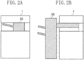
- Figs. 2A and 2B each schematically illustrate an example of a connection of the sheet processing apparatus 50 to the printing apparatus 1.
- Fig. 2A illustrates an example in which the sheet processing apparatus 50 is connected to the inside of the body of the printing apparatus 1.
- Fig. 2B illustrates an example in which the sheet processing apparatus 50 is connected to the outside of the body of the printing apparatus 1.
- the sheet processing apparatus 50 can execute stapling processing on a sheet discharged by the pair of discharge rollers 21 of the printing apparatus 1 and can also execute stapling processing on a sheet set directly on the sheet processing apparatus 50 by the user.
- Fig. 3 illustrates a configuration of the stapler 51 of the sheet processing apparatus 50.
- Fig. 3 is a cross sectional view illustrating the sheet processing apparatus 50 viewed from the top.
- a lower side of Fig. 3 corresponds to a front surface side (front side) of the printing apparatus 1 illustrated in Fig. 1 .
- the stapler 51 is provided to be movable in a direction of an arrow along a moving path 101.
- the stapler 51 has two roles. One of the roles of the stapler 51 is to perform stapling processing on a sheet S1 discharged from the printing apparatus 1. The other one of the roles of the stapler 51 is to perform stapling processing on a sheet S2 inserted in the sheet insertion slit 53.
- a stapler moving motor 164 ( Fig. 4 ) is driven to move the stapler 51 along the moving path 101 so that the stapling processing can be performed at any of positions X1, X2..., Xn-1, and Xn.
- the stapler 51 is also configured to be movable in upward and downward directions (vertical direction).
- the stapling processing needs to be performed on the sheet S2 inserted in the sheet insertion slit 53.
- the sheet insertion slit 53 is in the front surface (front side) of the sheet processing apparatus 50.
- the stapler 51 is moved to a position M at the front surface side (front side) of the sheet processing apparatus 50.
- the stapler 51 may hinder the sheet conveyance if the stapler 51 is located on the path through which the sheet S1 is conveyed. Thus, when the stapling processing with the stapler 51 is not executed, the stapler 51 is evacuated to a position X0 where the stapler 51 is not likely to hinder the sheet conveyance.
- Fig. 4 is a hardware configuration diagram illustrating the control system of the printing apparatus 1 and the sheet processing apparatus 50.
- the printing apparatus 1 includes a control board 59 including a central processing unit (CPU) 161, a power source 60, and an operation unit 65.
- the sheet processing apparatus 50 includes a control board 58 including a CPU 162, etc., a sheet detection sensor 54, a stapler position detection sensor 165, a stapler motor 163, the stapler moving motor 164, etc.
- the CPU 161 of the printing apparatus 1 controls each unit of the printing apparatus 1. Further, the CPU 161 reads a control program stored in a read-only memory (ROM) 173 to perform control relating to the sheet processing.
- a random access memory (RAM) 174 is used as a temporary storage area such as a main memory of the CPU 161, a work area, etc. While one CPU 161 uses one memory (RAM 173) to execute processing specified in a flow chart described below in the printing apparatus 1, any other configuration can be adopted. For example, a plurality of CPUs and a plurality of RAMs or a hard disk drive (HDD) or a solid state drive (SSD) may cooperate to execute processing. Further, a part of the processing described below may be executed by use of a hardware circuit such as an application specific integrated circuit (ASIC), etc.
- ASIC application specific integrated circuit
- the CPU 161 functions as follows. Specifically, the printing apparatus 1 is remained in the power saving mode, and the sheet processing apparatus 50 is recovered from the power saving mode.
- the power source 60 includes a non all-night power source 61, an all-night power source 62, a relay A 63, and a relay B 64.
- the non all-night power source 61 is connected to the control board 58 via the relay A 63 and to the control board 59 via the relay B 64.
- the all-night power source 62 is connected to the CPU 161 of the control board 59 and to a sensor interface (IF) circuit 71 of the control board 58.
- IF sensor interface
- the non all-night power source 61 is a power source capable of supplying power or stopping the supply of power according to the control by the CPU 161.
- the all-night power source 62 is a power source configured to constantly supply power with a power source plug of the printing apparatus 1 inserted in a power source outlet.
- a main power source switch (SW) 67 is a switch that is operated to turn on or off the power source of the printing apparatus 1.
- the operation unit 65 is a user interface (display, reception unit) for setting various types of settings with respect to the printing apparatus 1 and the sheet processing apparatus 50.
- the operation unit 65 includes a power saving SW 66, which is operated to change the printing apparatus 1 to the power saving mode or recover the printing apparatus 1 from the power saving mode.
- the CPU 162 of the sheet processing apparatus 50 is connected to the CPU 161 of the printing apparatus 1, and the CPUs 161 and 162 communicate with each other to detect the states of the printing apparatus 1 and the sheet processing apparatus 50. Further, the CPU 162 reads a control program stored in a ROM 171 to perform control relating to the sheet processing.
- a RAM 172 is used as a temporary storage area such as a main memory of the CPU 162, a work area, etc. While one CPU 162 uses one memory (RAM 172) to execute processing specified in a flow chart described below in the sheet processing apparatus 50, any other configuration can be adopted. For example, a plurality of CPUs and a plurality of RAMs or a HDD or a SSD may cooperate to execute processing. Further, a part of the processing described below may be executed by use of a hardware circuit such as an ASIC, etc.
- the CPU 162 of the sheet processing apparatus 50 is connected to the execution button 55, the sensor IF circuits 71, 72, and 73, and motor driving circuits 74, 75, and 76.
- the CPU 162 controls the respective units of the sheet processing apparatus 50 via the foregoing circuits.
- the CPU 162 performs control to move the stapler 51 to the position M when the sheet processing apparatus 50 is changed to the power saving mode.
- the sheet detection sensor 56 detects whether there is a sheet in the sheet alignment unit 57, and transmits a notification to the CPU 162 via the sensor IF circuit 72.
- the sheet detection sensor 54 detects whether there is a sheet in the sheet insertion slit 53, and transmits a notification to the CPU 162 via the sensor IF circuit 71.
- the stapler position detection sensor 165 is located to face the moving path 101 of the stapler 51 (refer to Fig. 3 ) and detects the position of the stapler 51. Further, the stapler position detection sensor 165 notifies the CPU 162 of a detection result via the sensor IF circuit 73.
- the stapler motor 163 is provided in the stapler 51 and driven by the motor driving circuit 75 to drive the stapler 51. In this way, stapling processing is performed on the sheet by the stapler 51.
- the stapler moving motor 164 is driven by the motor driving circuit 74 to move the stapler 51 to an arbitrary position as described above.
- the position of the stapler 51 is controlled by the CPU 162 based on a result of the detection by the stapler position detection sensor 165.
- a stapler motor 166 is provided in the stapler 52 and driven by the driving circuit 76 to drive the stapler 52. In this way, stapleless binding processing is performed on the sheet by the stapler 52.
- the execution button 55 transmits to the CPU 162 a signal corresponding to the press. Further, the lighting or blinking of the LED included in the execution button 55 is controlled by the CPU 162.
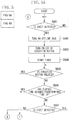
- Fig. 5 is a flow chart illustrating operations of the sheet processing apparatus 50 at the time of executing stapling processing on a sheet by the offline stapling function.
- the CPU 162 of the sheet processing apparatus 50 executes a control program stored in the ROM 171 to realize each operation (step) specified in the flow chart of Fig. 5 (A and B).
- step S501 whether a sheet is detected by the sheet detection sensor 54 is determined. If it is determined that a sheet is detected (YES in step S501), the processing proceeds to step S502. On the other hand, if it is determined that no sheet is detected (NO in step S501), the CPU 162 waits until a sheet is detected.
- step S502 the offline mode is turned on.
- the offline mode is turned on, the printing of an image by the printing apparatus 1 is restricted.
- step S503 the LED of the execution button 55 is turned on. By seeing the lighting of the LED of the execution button 55, the user can recognize that the execution button 55 can be pressed (an instruction to execute sheet processing can be given). Since the press of the execution button 55 is not detected until the operation in step S503 is performed, even if the execution button 55 is pressed before the operation in step S503 is performed, no stapling processing is executed.
- step S504 a timer provided to the sheet processing apparatus 50 is started.
- step S505 whether the execution button 55 is pressed is determined. If it is determined that the execution button 55 is pressed (YES in step S505), the processing proceeds to step S508. On the other hand, if it is determined that the execution button 55 is not pressed (NO in step S505), the processing proceeds to step S506. In step S506, it is determined whether an elapsed time measured by the timer started in step S504 has reached a predetermined time T1. If it is determined that the elapsed time has reached the predetermined time T1 (YES in step S506), the processing proceeds to step S508.
- step S506 if it is determined that the elapsed time has not reached the predetermined time T1 (NO in step S506), the processing proceeds to step S507. While the predetermined time T1 is three seconds in the present exemplary embodiment, the predetermined time T1 may be any time period other than three seconds and may be changed and set by the user.
- step S507 whether a sheet is detected by the sheet detection sensor 54 is determined. If it is determined that a sheet is detected (YES in step S507), the processing returns to step S505. On the other hand, if it is determined that no sheet is detected (NO in step S507), the processing proceeds to step S516.
- step S505 sheet processing is (manually) executed in response to a user operation.
- sheet processing is (automatically) executed in response to an elapse of a predetermined time.
- a possible case where the processing proceeds from step S507 to step S516 is a case where the user sets a sheet once, but changes the user's mind not to execute stapling processing and removes the sheet, etc.
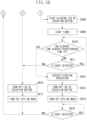
- step S508 the blinking of the LED of the execution button 55 is started. By seeing the blinking of the LED of the execution button 55, the user can recognize that the sheet processing will be executed soon.
- step S509 a timer provided to the sheet processing apparatus 50 is started. This timer may be the same as or different from the timer that is started in step S504. In the case of using the same timer, processing to reset the timer is required when the processing proceeds from step S508 to step S509.
- step S510 it is determined whether an elapsed time measured by the timer started in step S509 has reached a predetermined time T2. If it is determined that the elapsed time has reached the predetermined time T2 (YES in step S510), the processing proceeds to step S512. On the other hand, if it is determined that the elapsed time has not reached the predetermined time T2 (NO in step S510), the processing proceeds to step S511. While the predetermined time T2 is one second in the present exemplary embodiment, the predetermined time T2 may be any time period other than one second and may be changed and set by the user.
- step S511 whether a sheet is detected by the sheet detection sensor 54 is determined. If it is determined that a sheet is detected (YES in step S511), the processing returns to step S510. On the other hand, if it is determined that no sheet is detected (NO in step S511), the processing proceeds to step S516.
- a possible case where the processing proceeds from step S511 to step S516 is a case where the predetermined time T1 has elapsed since the sheet was set by the user or a case where the user presses the execution button 55 once, but changes the user's mind not to execute stapling processing and removes the sheet, etc.
- step S512 the CPU 162 causes the stapler 51 to execute stapling processing on a plurality of sheets set in the sheet processing apparatus 50 (a plurality of sheets inserted in the sheet insertion slit 53).
- step S513 the LED of the execution button 55 is turned off.
- step S514 the offline mode is turned off to cancel the printing restriction. In other words, the printing restriction is cancelled in response to the completion of the stapling processing in the offline mode.
- step S515 whether a sheet is detected by the sheet detection sensor 54 is determined. If it is determined that no sheet is detected (NO in step S515), the processing returns to step S501. On the other hand, if it is determined that a sheet is detected (YES in step S515), the CPU 162 waits until the sheet detection sensor 54 no longer detects a sheet. The condition that the sheet detection sensor 54 no longer detects a sheet is set as a condition for returning to step S501 so that re-execution of the stapling processing at the same position on the same sheet is prevented in a case where the sheet is still set even after the stapling processing is executed. In step S516, the LED of the execution button 55 is turned off. In step S517, the offline mode is turned off to cancel the printing restriction, and then the processing returns to step S501.
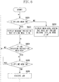
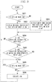
- Fig. 6 is a flow chart illustrating operations of the printing apparatus 1 at the time of receiving a job execution instruction.
- the CPU 161 of the printing apparatus 1 executes a control program stored in the ROM 173 to realize each operation (step) specified in the flow chart of Fig. 6 .
- step S601 whether the offline mode of the sheet processing apparatus 50 is on is determined. This determination is performed by performing inquiry from the printing apparatus 1 to the sheet processing apparatus 50. If it is determined that the offline mode is on (YES in step S601), the processing proceeds to step S602. On the other hand, if it is determined that the offline mode is not on (NO in step S601), the processing proceeds to step S603. In step S602, a message indicating that the offline mode is on is displayed.
- Fig. 7 illustrates an example of a main menu screen which is an operation screen displayed on the operation unit 65 of the printing apparatus 1 and on which a list of the plurality of functions of the printing apparatus 1 is displayed.
- the message "Offline mode is on” is displayed on a lower part of the main menu screen. By seeing the message, the user can recognize that the printing is currently restricted.
- the contents of the message are not limited to that illustrated in Fig. 7 and may be, for example, "Printing is restricted," or "Stapling is being executed in the finisher.”
- step S603 a main menu screen that does not include the message "Offline mode is on” is displayed. In the case where the processing proceeds to step S603 with the message "Offline mode is on” being displayed, the message is hidden in step S603.
- step S604 whether a job execution instruction is received is determined.
- the user can give a job execution instruction by pressing a start button included in the operation unit 65 of the printing apparatus 1. If it is determined that a job execution instruction is received (YES in step S604), the processing proceeds to step S605. On the other hand, if it is determined that no job execution instruction is received (NO in step S604), the processing returns to step S601.
- step S605 as in step S601, whether the offline mode of the sheet processing apparatus 50 is on is determined. If it is determined that the offline mode is not on (NO in step S605), the processing proceeds to step S606. On the other hand, if it is determined that the offline mode is on (YES in step S605), the CPU 161 waits until the offline mode becomes off. The CPU 161 waits in order to restrict the printing while the offline mode is on. In step S606, the job, the execution instruction of which has been received, is executed. More specifically, in a case where the job is a print job, an image is printed on a sheet.
- the printing of an image by the printing apparatus 1 is restricted in response to detection of a sheet by the sheet detection sensor 54 on which stapling processing is performed by the stapler 51 not in association with the printing of an image by the printing apparatus 1.
- the printing of an image can be restricted without requiring the user to perform a complicated operation in the case where the sheet processing is to be performed not in association with the printing of an image.
- a second exemplary embodiment of the present invention will be described below.
- the example is described in which execution of all jobs by the printing apparatus 1 is uniformly restricted in response to detection of a sheet by the sheet detection sensor 54.
- an example will be described in which whether to restrict execution of a job is switched according to the type of the job.
- an example will be described in which a job is not restricted in a case where the job is already being executed by the printing apparatus 1 when a sheet is detected by the sheet detection sensor 54. Only the points that are different from those in the first exemplary embodiment will be described, and other points are similar to those in the first exemplary embodiment.
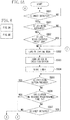
- Fig. 8 (A and B) is a flow chart illustrating operations of the sheet processing apparatus 50 at the time of performing stapling processing on a sheet by the offline stapling function.
- Fig. 8 (A and B) corresponds to the flow chart in Fig. 5 (A and B) described in the first exemplary embodiment.
- the flow chart in Fig. 8 (A and B) is different from the flow chart in Fig. 5 (A and B) in that steps S801 and S802 are added.
- step S501 whether a sheet is detected by the sheet detection sensor 54 is determined. If it is determined that a sheet is detected (YES in step S501), the processing proceeds to step S801. On the other hand, if it is determined that no sheet is detected (NO in step S501), the CPU 162 waits until a sheet is detected.
- step S801 whether the printing apparatus 1 is executing a job is determined. If it is determined that the printing apparatus 1 is executing a job (YES in step S801), the processing proceeds to step S802. On the other hand, if it is determined that the printing apparatus 1 is not executing a job (NO in step S801), the processing proceeds to step S502. In step S802, whether the job being executed is a print job is determined. If it is determined that the job being executed is a print job (YES in step S802), the processing proceeds to step S515. On the other hand if it is determined that the job being executed is not a print job (NO in step S802), the processing proceeds to step S502.
- step S801 or S802 to step S502 the offline stapling function can be used, and thus steps S502 to S517 described above with reference to the flow chart of Fig. 5 (A and B) are executed.
- step S802 to step S515 the offline stapling function cannot be used, so the offline mode is not turned on (i.e., restriction of the printing is not performed).
- Examples of a job other than a print job include a job of scanning a document and sending image data, a job of scanning a document and saving image data, etc. These jobs do not use the sheet processing apparatus 50, so even if any one of these jobs is being executed, the offline stapling function can be used.
- step S502 and the subsequent steps are not performed even if the execution of the print job is completed with the sheet inserted in the sheet insertion slit 53.
- the sheet remaining inserted in the sheet insertion slit 53 needs to be removed and then inserted again. This arrangement is made because it is difficult for the user to predict the exact timing of the completion of the execution of the print job and if stapling processing is unexpectedly executed, an error such as pushing of a staple into an unintended position may occur.
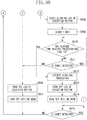
- Fig. 9 is a flow chart illustrating operations of the printing apparatus 1 at the time of receiving a job execution instruction.
- Fig. 9 corresponds to the flow chart in Fig. 6 described in the first exemplary embodiment.
- the flow chart in Fig. 9 is different from the flow chart in Fig. 6 in that step S901 is added.
- step S604 whether a job execution instruction is received is determined.
- the user can give a job execution instruction by pressing the start button included in the operation unit 65 of the printing apparatus 1. If it is determined that a job execution instruction is received (YES in step S604), the processing proceeds to step S901. On the other hand, if it is determined that no job execution instruction is received (NO in step S604), the processing returns to step S601.
- step S901 whether the job, the execution instruction of which has been received, is a print job is determined. If it is determined that the job is a print job (YES in step S901), the processing proceeds to step S605. On the other hand, if it is determined that the job is not a print job (NO in step S901), the processing proceeds to step S606.
- Examples of jobs other than a print job include a job of scanning a document and sending image data, a job of scanning a document and saving image data, etc.
- the processing is to proceed from step S901 to step S606 because these jobs do not use the sheet processing apparatus 50, so even if the offline mode of the sheet processing apparatus 50 is on, it is not necessary to wait until the offline mode becomes off.
- processing up to print data processing raster image processor (RIP) processing and image processing
- RIP raster image processor
- an exemplary embodiment of the present invention is also applicable to stapleless binding processing by the stapler 52 without the use of a staple. Further, an exemplary embodiment of the present invention is also applicable to punching processing by a puncher (not illustrated).
- Embodiment (s) of the present invention can also be realized by a computer of a system or apparatus that reads out and executes computer executable instructions (e.g., one or more programs) recorded on a storage medium (which may also be referred to more fully as a 'non-transitory computer-readable storage medium') to perform the functions of one or more of the above-described embodiment (s) and/or that includes one or more circuits (e.g., application specific integrated circuit (ASIC)) for performing the functions of one or more of the above-described embodiment(s), and by a method performed by the computer of the system or apparatus by, for example, reading out and executing the computer executable instructions from the storage medium to perform the functions of one or more of the above-described embodiment(s) and/or controlling the one or more circuits to perform the functions of one or more of the above-described embodiment (s) .
- ASIC application specific integrated circuit
- the computer may comprise one or more processors (e.g., central processing unit (CPU), micro processing unit (MPU)) and may include a network of separate computers or separate processors to read out and execute the computer executable instructions.
- the computer executable instructions may be provided to the computer, for example, from a network or the storage medium.
- the storage medium may include, for example, one or more of a hard disk, a random-access memory (RAM), a read only memory (ROM), a storage of distributed computing systems, an optical disk (such as a compact disc (CD), digital versatile disc (DVD), or Blu-ray Disc (BD)TM), a flash memory device, a memory card, and the like.
Description
- The present invention relates to a printing system capable of performing processing on a sheet.
- Conventionally, sheet processing apparatuses configured to perform processing on a sheet are known. Specific examples of known processing performed on a sheet include binding processing (stapling) for binding a plurality of sheets together with a staple, stapleless binding processing for binding a plurality of sheets together by swaging the sheets without a staple, punching processing for punching a sheet, etc. The foregoing processing will be referred to as "sheet processing."
- One example of the sheet processing apparatuses is a sheet processing apparatus that is connected to a printing apparatus configured to print an image on a sheet when the sheet processing apparatus is used. In the case where the sheet processing apparatus and the printing apparatus are connected to each other, the sheet processing apparatus is connected on the downstream side of the printing apparatus in a direction in which a sheet is conveyed. The sheet processing apparatus receives from the printing apparatus a sheet on which an image is printed, and performs sheet processing on the sheet.
- Further, there is known a sheet processing apparatus capable of performing sheet processing not in association with the printing of an image by a printing apparatus as well as performing sheet processing in association with the printing of an image by the printing apparatus. Japanese Patent Application Laid-Open Nos.
2014-162590 2011-003005 2006-264978 - In a sheet processing apparatus connected to a printing apparatus, when sheet processing is to be performed on a sheet set directly on the sheet processing apparatus by a user, there may be a conflict between the sheet processing and the conveyance of a sheet from the printing apparatus. More specifically, when the sheet processing is to be performed on the sheet set directly on the sheet processing apparatus by the user, if a printed sheet is conveyed from the printing apparatus, the operation of the user may be disturbed. Further, the sheet set directly on the sheet processing apparatus by the user may collide with a sheet conveyed from the printing apparatus to cause a jam error.
- The foregoing problems are not considered in Japanese Patent Application Laid-Open Nos.
2014-162590 2011-003005 2006-264978 - According to Japanese Patent Application Laid-Open No.
2006-264978 -
Document EP 2 264 544 A2 discloses a control method for controlling a printing system includes selectively executing an inline job for executing post-processing on a sheet printed by a printing apparatus by using a post-processing apparatus and an offline job for executing post-processing on a sheet without executing printing by the printing apparatus by using the post-processing apparatus, and restricting, if a sheet has been set in a paper feed unit that is a paper feed source of the offline job to be executed, execution of the inline job. - Document
US 2014/369731 A1 discloses a printing apparatus that shifts to a job processable state by releasing a manual stapling mode in response to an execution instruction of a predetermined job requested by a user. - Document
JP S63 139876 A - Document
US 2010/053680 A1 discloses a printing system that conveys sheets printed by a printing unit to a sheet processing unit connected to the printing unit and causes the sheet processing unit to perform post processing on the sheet. - Document
US 5 060 922 A discloses a copying paper processing apparatus comprising a sorter, a stapling device for stapling sheets of copying paper sorted by the sorter, and a device for automatically selecting and setting a sort mode when a staple mode is selected and set. - Document
US 2010/321706 A1 discloses a control method for controlling a printing system that includes selectively executing an inline job and an offline job, where the inline job is for executing post-processing on a sheet printed by a printing apparatus by using a post-processing apparatus and the offline job is for executing post-processing on a sheet without executing printing by the printing apparatus by using the post-processing apparatus. The method includes detecting that a sheet has been set in a paper feed unit, setting whether to execute an offline job that uses the sheet if the sheet is detected as being set in the paper feed unit, and controlling the post-processing apparatus to automatically start post-processing corresponding to the offline job in a case where both the system is set to execute the offline job and the system detects that the sheet has been set in the paper feed unit. - The present invention is directed to a printing system, a printing system control method, and a program which are capable of restricting the printing of an image without requiring a user to perform a complicated operation when sheet processing is performed not in association with the printing of an image.
- According to a first aspect of the present invention, there is provided a printing system as specified in
claims 1 to 7. According to a second aspect of the present invention, there is provided a method of controlling a printing system as specified inclaim 8. According to a third aspect of the present invention, there is provided a program that causes a computer to perform a method for controlling a printing system as specified in claim 9. - Further features of the present invention will become apparent from the following description of exemplary embodiments with reference to the attached drawings.
-
-
Fig. 1 is a cross sectional view illustrating a printing system according to an exemplary embodiment of the present invention. -
Figs. 2A and 2B are schematic views illustrating an example of a connection between a printing apparatus and a sheet processing apparatus according to an exemplary embodiment of the present invention. -
Fig. 3 illustrates a configuration of a stapler of a sheet processing apparatus according to an exemplary embodiment of the present invention. -
Fig. 4 is a hardware configuration diagram illustrating a control system of a printing apparatus and a sheet processing apparatus according to an exemplary embodiment of the present invention. -
Fig. 5 (A and B) is a flow chart illustrating operations of a sheet processing apparatus according to an exemplary embodiment of the present invention. -
Fig. 6 is a flow chart illustrating operations of a printing apparatus according to an exemplary embodiment of the present invention. -
Fig. 7 illustrates an example of an operation screen displayed on a printing apparatus according to an exemplary embodiment of the present invention. -
Fig. 8 (A and B) is a flow chart illustrating operations of a sheet processing apparatus according to an exemplary embodiment of the present invention. -
Fig. 9 is a flow chart illustrating operations of a printing apparatus according to an exemplary embodiment of the present invention. - Various exemplary embodiments of the present invention will be described in detail below with reference to the drawings. The present invention is not limited to the disclosed exemplary embodiments and not all the combinations of features described in the exemplary embodiments are always essential to a technical solution provided by the present invention.
-
Fig. 1 is a cross sectional view illustrating an entire printing system including asheet processing apparatus 50 according to a first exemplary embodiment of the present invention and aprinting apparatus 1 to which thesheet processing apparatus 50 is connected. While thesheet processing apparatus 50 and theprinting apparatus 1 are described as separate apparatuses in the present exemplary embodiment, an entire apparatus including thesheet processing apparatus 50 may be referred to as a printing apparatus, or an entire apparatus including theprinting apparatus 1 may be referred to as a sheet processing apparatus. - The
printing apparatus 1 is roughly divided into two devices, i.e., ascanner 2 and aprinter 3. Thescanner 2 reads an image on an original document to generate image data. Theprinter 3 forms an image on a sheet. An upper part of thescanner 2 includes aplaten glass 4 including a transparent glass plate. An original document D set in a predetermined position on theplaten glass 4 with an image to be read facing downward is pressed and fixed by a document pressing plate 5. Alamp 6 and optical system components includingreflection mirrors platen glass 4. Thelamp 6 applies light to the original document D, and the reflection mirrors 8, 9, and 10 guide reflection light to animage processing unit 7. Thelamp 6 and the reflection mirrors 8, 9, and 10 are moved at a predetermined speed to scan the original document D. - The
printer 3 includes aphotosensitive drum 11, aprimary charging roller 12, arotary development unit 13, anintermediate transfer belt 14, atransfer roller 15, acleaner 16, etc. An electrostatic latent image is formed on a surface of thephotosensitive drum 11 by laser light applied by alaser unit 17 based on image data generated by reading an image on the original document D. Theprimary charging roller 12 uniformly charges the surface of thephotosensitive drum 11 before the application of the laser light. - The
rotary development unit 13 attaches magenta (M) toner, cyan (C) toner, yellow (Y) toner, and black (K) toner to the electrostatic latent image formed on the surface of thephotosensitive drum 11 to form a toner image. The toner image developed on the surface of thephotosensitive drum 11 is transferred onto theintermediate transfer belt 14, and the toner image transferred onto theintermediate transfer belt 14 is transferred by thetransfer roller 15 onto a sheet S. Thecleaner 16 removes residual toner on thephotosensitive drum 11 after the transfer of the toner image. - The
rotary development unit 13 employs a rotary development method, includes developingunits photosensitive drum 11, the developingunit 13K is rotated and moved to a development position near thephotosensitive drum 11 to perform development. When a full-color toner image is formed, therotary development unit 13 is rotated to position each of the developingunits - The sheet S onto which the toner image on the
intermediate transfer belt 14 is transferred is fed from acassette 18 or a manual sheet-feeding tray 20 to a transfer position. A fixingunit 19 is provided on the downstream side of thetransfer roller 15 in a conveying direction to fix the toner image on the conveyed sheet S. The sheet S on which the toner image is fixed is discharged by a pair ofdischarge rollers 21 from theprinting apparatus 1 to thesheet processing apparatus 50 located on the downstream side in the conveying direction. - The
sheet processing apparatus 50 is connected to a sheet discharge position of theprinting apparatus 1 and is communicable with theprinting apparatus 1 via a signal line (not illustrated). Thesheet processing apparatus 50 communicates with theprinting apparatus 1 to operate in cooperation with theprinting apparatus 1. Thesheet processing apparatus 50 includesstaplers discharge rollers 21. Thestapler 51 binds together the plurality of sheets S with a staple. On the other hand, thestapler 52 binds together the plurality of sheets S without a staple. Thestapler 51 is movable as described below with reference toFig. 3 and can execute binding processing at a plurality of positions. On the other hand, thestapler 52 is fixed in one position. Alternatively, thestapler 52 may be configured to be movable. Further, a puncher for punching a sheet, etc. may also be included in addition to the staplers. - The
sheet processing apparatus 50 includes asheet detection sensor 56 and asheet alignment unit 57. Thesheet detection sensor 56 detects the existence of the sheet S, and thesheet alignment unit 57 aligns the sheets S. Thesheet processing apparatus 50 detects with thesheet detection sensor 56 the sheet S conveyed to thesheet alignment unit 57 and executes binding processing (stapling) with thestapler 51 or binding processing (stapleless binding) with thestapler 52 according to a user specification. - Further, the
sheet processing apparatus 50 includes an offline stapling function to execute binding processing not on a sheet fed from thecassette 18 or the manual sheet-feedingtray 20 but on a sheet set directly on thesheet processing apparatus 50 by the user. In the case of using the offline stapling function, the binding processing with a staple by thestapler 51 is executed. A sheet insertion slit 53 is a portion (insertion portion) via which the user using the offline stapling function inserts a sheet subjected to the processing. The sheet insertion slit 53 has a form of a slit, and the user inserts a sheet into the slit. Asheet detection sensor 54 detects the insertion of the sheet in the sheet insertion slit 53. - If the
sheet detection sensor 54 detects a sheet, the mode is changed to an offline mode (offline mode is turned on). At the press of anexecution button 55 by the user while the offline mode is on, the stapling processing with thestapler 51 is executed. Further, even if theexecution button 55 is not pressed, the stapling processing is automatically executed if thesheet detection sensor 54 continues detecting a sheet for a predetermined time. - While the offline mode is on, the printing of an image by the
printing apparatus 1 is restricted so that no sheet is conveyed from theprinting apparatus 1 to thesheet processing apparatus 50. Further, theexecution button 55 includes a light emitting diode (LED) that can be lit and blinked, and the lighting or blinking of the LED notifies the user of the state of thesheet processing apparatus 50. The lighting of the LED indicates that theexecution button 55 can be pressed (i.e., execution of sheet processing can be instructed). Further, the blinking of the LED indicates that the sheet processing will be executed soon. Besides the notification using the LED, a message may be displayed or sound may be output to notify the user of the state of thesheet processing apparatus 50. -
Figs. 2A and 2B each schematically illustrate an example of a connection of thesheet processing apparatus 50 to theprinting apparatus 1.Fig. 2A illustrates an example in which thesheet processing apparatus 50 is connected to the inside of the body of theprinting apparatus 1.Fig. 2B illustrates an example in which thesheet processing apparatus 50 is connected to the outside of the body of theprinting apparatus 1. In either one of the connection forms, thesheet processing apparatus 50 can execute stapling processing on a sheet discharged by the pair ofdischarge rollers 21 of theprinting apparatus 1 and can also execute stapling processing on a sheet set directly on thesheet processing apparatus 50 by the user. -
Fig. 3 illustrates a configuration of thestapler 51 of thesheet processing apparatus 50.Fig. 3 is a cross sectional view illustrating thesheet processing apparatus 50 viewed from the top. A lower side ofFig. 3 corresponds to a front surface side (front side) of theprinting apparatus 1 illustrated inFig. 1 . Thestapler 51 is provided to be movable in a direction of an arrow along a movingpath 101. Thestapler 51 has two roles. One of the roles of thestapler 51 is to perform stapling processing on a sheet S1 discharged from theprinting apparatus 1. The other one of the roles of thestapler 51 is to perform stapling processing on a sheet S2 inserted in the sheet insertion slit 53. - To staple the sheet S1, stapling processing needs to be performed at a stapling position set by the user. Thus, a stapler moving motor 164 (
Fig. 4 ) is driven to move thestapler 51 along the movingpath 101 so that the stapling processing can be performed at any of positions X1, X2..., Xn-1, and Xn. Although not illustrated, thestapler 51 is also configured to be movable in upward and downward directions (vertical direction). - On the other hand, to staple the sheet S2, the stapling processing needs to be performed on the sheet S2 inserted in the sheet insertion slit 53. However, the sheet insertion slit 53 is in the front surface (front side) of the
sheet processing apparatus 50. Thus, when the stapling processing is to be executed on the sheet S2, thestapler 51 is moved to a position M at the front surface side (front side) of thesheet processing apparatus 50. - The
stapler 51 may hinder the sheet conveyance if thestapler 51 is located on the path through which the sheet S1 is conveyed. Thus, when the stapling processing with thestapler 51 is not executed, thestapler 51 is evacuated to a position X0 where thestapler 51 is not likely to hinder the sheet conveyance. - The following describes a configuration of a control system of the
printing apparatus 1 and thesheet processing apparatus 50.Fig. 4 is a hardware configuration diagram illustrating the control system of theprinting apparatus 1 and thesheet processing apparatus 50. InFig. 4 , theprinting apparatus 1 includes acontrol board 59 including a central processing unit (CPU) 161, apower source 60, and anoperation unit 65. Thesheet processing apparatus 50 includes acontrol board 58 including aCPU 162, etc., asheet detection sensor 54, a staplerposition detection sensor 165, astapler motor 163, thestapler moving motor 164, etc. - The
CPU 161 of theprinting apparatus 1 controls each unit of theprinting apparatus 1. Further, theCPU 161 reads a control program stored in a read-only memory (ROM) 173 to perform control relating to the sheet processing. A random access memory (RAM) 174 is used as a temporary storage area such as a main memory of theCPU 161, a work area, etc. While oneCPU 161 uses one memory (RAM 173) to execute processing specified in a flow chart described below in theprinting apparatus 1, any other configuration can be adopted. For example, a plurality of CPUs and a plurality of RAMs or a hard disk drive (HDD) or a solid state drive (SSD) may cooperate to execute processing. Further, a part of the processing described below may be executed by use of a hardware circuit such as an application specific integrated circuit (ASIC), etc. - In a case where insertion of a sheet in the sheet insertion slit 53 is detected while the
printing apparatus 1 and thesheet processing apparatus 50 are in a power saving mode, theCPU 161 functions as follows. Specifically, theprinting apparatus 1 is remained in the power saving mode, and thesheet processing apparatus 50 is recovered from the power saving mode. Thepower source 60 includes a non all-night power source 61, an all-night power source 62, arelay A 63, and arelay B 64. The non all-night power source 61 is connected to thecontrol board 58 via therelay A 63 and to thecontrol board 59 via therelay B 64. The all-night power source 62 is connected to theCPU 161 of thecontrol board 59 and to a sensor interface (IF)circuit 71 of thecontrol board 58. - The non all-
night power source 61 is a power source capable of supplying power or stopping the supply of power according to the control by theCPU 161. The all-night power source 62 is a power source configured to constantly supply power with a power source plug of theprinting apparatus 1 inserted in a power source outlet. A main power source switch (SW) 67 is a switch that is operated to turn on or off the power source of theprinting apparatus 1. Theoperation unit 65 is a user interface (display, reception unit) for setting various types of settings with respect to theprinting apparatus 1 and thesheet processing apparatus 50. Theoperation unit 65 includes apower saving SW 66, which is operated to change theprinting apparatus 1 to the power saving mode or recover theprinting apparatus 1 from the power saving mode. - The
CPU 162 of thesheet processing apparatus 50 is connected to theCPU 161 of theprinting apparatus 1, and theCPUs printing apparatus 1 and thesheet processing apparatus 50. Further, theCPU 162 reads a control program stored in aROM 171 to perform control relating to the sheet processing. ARAM 172 is used as a temporary storage area such as a main memory of theCPU 162, a work area, etc. While oneCPU 162 uses one memory (RAM 172) to execute processing specified in a flow chart described below in thesheet processing apparatus 50, any other configuration can be adopted. For example, a plurality of CPUs and a plurality of RAMs or a HDD or a SSD may cooperate to execute processing. Further, a part of the processing described below may be executed by use of a hardware circuit such as an ASIC, etc. - The
CPU 162 of thesheet processing apparatus 50 is connected to theexecution button 55, the sensor IFcircuits motor driving circuits CPU 162 controls the respective units of thesheet processing apparatus 50 via the foregoing circuits. TheCPU 162 performs control to move thestapler 51 to the position M when thesheet processing apparatus 50 is changed to the power saving mode. - The
sheet detection sensor 56 detects whether there is a sheet in thesheet alignment unit 57, and transmits a notification to theCPU 162 via the sensor IFcircuit 72. Thesheet detection sensor 54 detects whether there is a sheet in the sheet insertion slit 53, and transmits a notification to theCPU 162 via the sensor IFcircuit 71. The staplerposition detection sensor 165 is located to face the movingpath 101 of the stapler 51 (refer toFig. 3 ) and detects the position of thestapler 51. Further, the staplerposition detection sensor 165 notifies theCPU 162 of a detection result via the sensor IFcircuit 73. - The
stapler motor 163 is provided in thestapler 51 and driven by themotor driving circuit 75 to drive thestapler 51. In this way, stapling processing is performed on the sheet by thestapler 51. Thestapler moving motor 164 is driven by themotor driving circuit 74 to move thestapler 51 to an arbitrary position as described above. The position of thestapler 51 is controlled by theCPU 162 based on a result of the detection by the staplerposition detection sensor 165. - A
stapler motor 166 is provided in thestapler 52 and driven by the drivingcircuit 76 to drive thestapler 52. In this way, stapleless binding processing is performed on the sheet by thestapler 52. At the press of theexecution button 55 by the user, theexecution button 55 transmits to the CPU 162 a signal corresponding to the press. Further, the lighting or blinking of the LED included in theexecution button 55 is controlled by theCPU 162. -
Fig. 5 (A and B) is a flow chart illustrating operations of thesheet processing apparatus 50 at the time of executing stapling processing on a sheet by the offline stapling function. TheCPU 162 of thesheet processing apparatus 50 executes a control program stored in theROM 171 to realize each operation (step) specified in the flow chart ofFig. 5 (A and B). - In step S501, whether a sheet is detected by the
sheet detection sensor 54 is determined. If it is determined that a sheet is detected (YES in step S501), the processing proceeds to step S502. On the other hand, if it is determined that no sheet is detected (NO in step S501), theCPU 162 waits until a sheet is detected. - In step S502, the offline mode is turned on. When the offline mode is turned on, the printing of an image by the
printing apparatus 1 is restricted. In step S503, the LED of theexecution button 55 is turned on. By seeing the lighting of the LED of theexecution button 55, the user can recognize that theexecution button 55 can be pressed (an instruction to execute sheet processing can be given). Since the press of theexecution button 55 is not detected until the operation in step S503 is performed, even if theexecution button 55 is pressed before the operation in step S503 is performed, no stapling processing is executed. In step S504, a timer provided to thesheet processing apparatus 50 is started. - In step S505, whether the
execution button 55 is pressed is determined. If it is determined that theexecution button 55 is pressed (YES in step S505), the processing proceeds to step S508. On the other hand, if it is determined that theexecution button 55 is not pressed (NO in step S505), the processing proceeds to step S506. In step S506, it is determined whether an elapsed time measured by the timer started in step S504 has reached a predetermined time T1. If it is determined that the elapsed time has reached the predetermined time T1 (YES in step S506), the processing proceeds to step S508. On the other hand, if it is determined that the elapsed time has not reached the predetermined time T1 (NO in step S506), the processing proceeds to step S507. While the predetermined time T1 is three seconds in the present exemplary embodiment, the predetermined time T1 may be any time period other than three seconds and may be changed and set by the user. In step S507, whether a sheet is detected by thesheet detection sensor 54 is determined. If it is determined that a sheet is detected (YES in step S507), the processing returns to step S505. On the other hand, if it is determined that no sheet is detected (NO in step S507), the processing proceeds to step S516. - In the case where the processing proceeds from step S505 to step S508, sheet processing is (manually) executed in response to a user operation. On the other hand, in the case where the processing proceeds from step S506 to step S508, sheet processing is (automatically) executed in response to an elapse of a predetermined time. A possible case where the processing proceeds from step S507 to step S516 is a case where the user sets a sheet once, but changes the user's mind not to execute stapling processing and removes the sheet, etc.
- In step S508, the blinking of the LED of the
execution button 55 is started. By seeing the blinking of the LED of theexecution button 55, the user can recognize that the sheet processing will be executed soon. In step S509, a timer provided to thesheet processing apparatus 50 is started. This timer may be the same as or different from the timer that is started in step S504. In the case of using the same timer, processing to reset the timer is required when the processing proceeds from step S508 to step S509. - In step S510, it is determined whether an elapsed time measured by the timer started in step S509 has reached a predetermined time T2. If it is determined that the elapsed time has reached the predetermined time T2 (YES in step S510), the processing proceeds to step S512. On the other hand, if it is determined that the elapsed time has not reached the predetermined time T2 (NO in step S510), the processing proceeds to step S511. While the predetermined time T2 is one second in the present exemplary embodiment, the predetermined time T2 may be any time period other than one second and may be changed and set by the user.
- In step S511, whether a sheet is detected by the
sheet detection sensor 54 is determined. If it is determined that a sheet is detected (YES in step S511), the processing returns to step S510. On the other hand, if it is determined that no sheet is detected (NO in step S511), the processing proceeds to step S516. A possible case where the processing proceeds from step S511 to step S516 is a case where the predetermined time T1 has elapsed since the sheet was set by the user or a case where the user presses theexecution button 55 once, but changes the user's mind not to execute stapling processing and removes the sheet, etc. - In step S512, the
CPU 162 causes thestapler 51 to execute stapling processing on a plurality of sheets set in the sheet processing apparatus 50 (a plurality of sheets inserted in the sheet insertion slit 53). In step S513, the LED of theexecution button 55 is turned off. In step S514, the offline mode is turned off to cancel the printing restriction. In other words, the printing restriction is cancelled in response to the completion of the stapling processing in the offline mode. - In step S515, whether a sheet is detected by the
sheet detection sensor 54 is determined. If it is determined that no sheet is detected (NO in step S515), the processing returns to step S501. On the other hand, if it is determined that a sheet is detected (YES in step S515), theCPU 162 waits until thesheet detection sensor 54 no longer detects a sheet. The condition that thesheet detection sensor 54 no longer detects a sheet is set as a condition for returning to step S501 so that re-execution of the stapling processing at the same position on the same sheet is prevented in a case where the sheet is still set even after the stapling processing is executed. In step S516, the LED of theexecution button 55 is turned off. In step S517, the offline mode is turned off to cancel the printing restriction, and then the processing returns to step S501. -
Fig. 6 is a flow chart illustrating operations of theprinting apparatus 1 at the time of receiving a job execution instruction. TheCPU 161 of theprinting apparatus 1 executes a control program stored in theROM 173 to realize each operation (step) specified in the flow chart ofFig. 6 . - In step S601, whether the offline mode of the
sheet processing apparatus 50 is on is determined. This determination is performed by performing inquiry from theprinting apparatus 1 to thesheet processing apparatus 50. If it is determined that the offline mode is on (YES in step S601), the processing proceeds to step S602. On the other hand, if it is determined that the offline mode is not on (NO in step S601), the processing proceeds to step S603. In step S602, a message indicating that the offline mode is on is displayed. -
Fig. 7 illustrates an example of a main menu screen which is an operation screen displayed on theoperation unit 65 of theprinting apparatus 1 and on which a list of the plurality of functions of theprinting apparatus 1 is displayed. In step 602, the message "Offline mode is on" is displayed on a lower part of the main menu screen. By seeing the message, the user can recognize that the printing is currently restricted. The contents of the message are not limited to that illustrated inFig. 7 and may be, for example, "Printing is restricted," or "Stapling is being executed in the finisher." - In step S603, a main menu screen that does not include the message "Offline mode is on" is displayed. In the case where the processing proceeds to step S603 with the message "Offline mode is on" being displayed, the message is hidden in step S603.
- In step S604, whether a job execution instruction is received is determined. The user can give a job execution instruction by pressing a start button included in the
operation unit 65 of theprinting apparatus 1. If it is determined that a job execution instruction is received (YES in step S604), the processing proceeds to step S605. On the other hand, if it is determined that no job execution instruction is received (NO in step S604), the processing returns to step S601. - In step S605, as in step S601, whether the offline mode of the
sheet processing apparatus 50 is on is determined. If it is determined that the offline mode is not on (NO in step S605), the processing proceeds to step S606. On the other hand, if it is determined that the offline mode is on (YES in step S605), theCPU 161 waits until the offline mode becomes off. TheCPU 161 waits in order to restrict the printing while the offline mode is on. In step S606, the job, the execution instruction of which has been received, is executed. More specifically, in a case where the job is a print job, an image is printed on a sheet. - As described above, in the first exemplary embodiment, the printing of an image by the
printing apparatus 1 is restricted in response to detection of a sheet by thesheet detection sensor 54 on which stapling processing is performed by thestapler 51 not in association with the printing of an image by theprinting apparatus 1. In this way, the printing of an image can be restricted without requiring the user to perform a complicated operation in the case where the sheet processing is to be performed not in association with the printing of an image. - A second exemplary embodiment of the present invention will be described below. In the first exemplary embodiment, the example is described in which execution of all jobs by the
printing apparatus 1 is uniformly restricted in response to detection of a sheet by thesheet detection sensor 54. On the contrary, in the present exemplary embodiment, an example will be described in which whether to restrict execution of a job is switched according to the type of the job. Further, in the present exemplary embodiment, an example will be described in which a job is not restricted in a case where the job is already being executed by theprinting apparatus 1 when a sheet is detected by thesheet detection sensor 54. Only the points that are different from those in the first exemplary embodiment will be described, and other points are similar to those in the first exemplary embodiment. -
Fig. 8 (A and B) is a flow chart illustrating operations of thesheet processing apparatus 50 at the time of performing stapling processing on a sheet by the offline stapling function.Fig. 8 (A and B) corresponds to the flow chart inFig. 5 (A and B) described in the first exemplary embodiment. The flow chart inFig. 8 (A and B) is different from the flow chart inFig. 5 (A and B) in that steps S801 and S802 are added. - In step S501, whether a sheet is detected by the
sheet detection sensor 54 is determined. If it is determined that a sheet is detected (YES in step S501), the processing proceeds to step S801. On the other hand, if it is determined that no sheet is detected (NO in step S501), theCPU 162 waits until a sheet is detected. - In step S801, whether the
printing apparatus 1 is executing a job is determined. If it is determined that theprinting apparatus 1 is executing a job (YES in step S801), the processing proceeds to step S802. On the other hand, if it is determined that theprinting apparatus 1 is not executing a job (NO in step S801), the processing proceeds to step S502. In step S802, whether the job being executed is a print job is determined. If it is determined that the job being executed is a print job (YES in step S802), the processing proceeds to step S515. On the other hand if it is determined that the job being executed is not a print job (NO in step S802), the processing proceeds to step S502. - In the case where the processing proceeds from step S801 or S802 to step S502, the offline stapling function can be used, and thus steps S502 to S517 described above with reference to the flow chart of
Fig. 5 (A and B) are executed. On the other hand, in the case where the processing proceeds from step S802 to step S515, the offline stapling function cannot be used, so the offline mode is not turned on (i.e., restriction of the printing is not performed). Examples of a job other than a print job include a job of scanning a document and sending image data, a job of scanning a document and saving image data, etc. These jobs do not use thesheet processing apparatus 50, so even if any one of these jobs is being executed, the offline stapling function can be used. - Since the processing is to proceed not to step S501 but to step S515 in the case where it is determined that the job is a print job, step S502 and the subsequent steps are not performed even if the execution of the print job is completed with the sheet inserted in the sheet insertion slit 53. In order to execute step S502 and the subsequent steps, the sheet remaining inserted in the sheet insertion slit 53 needs to be removed and then inserted again. This arrangement is made because it is difficult for the user to predict the exact timing of the completion of the execution of the print job and if stapling processing is unexpectedly executed, an error such as pushing of a staple into an unintended position may occur.
-
Fig. 9 is a flow chart illustrating operations of theprinting apparatus 1 at the time of receiving a job execution instruction.Fig. 9 corresponds to the flow chart inFig. 6 described in the first exemplary embodiment. The flow chart inFig. 9 is different from the flow chart inFig. 6 in that step S901 is added. - In step S604, whether a job execution instruction is received is determined. The user can give a job execution instruction by pressing the start button included in the
operation unit 65 of theprinting apparatus 1. If it is determined that a job execution instruction is received (YES in step S604), the processing proceeds to step S901. On the other hand, if it is determined that no job execution instruction is received (NO in step S604), the processing returns to step S601. - In step S901, whether the job, the execution instruction of which has been received, is a print job is determined. If it is determined that the job is a print job (YES in step S901), the processing proceeds to step S605. On the other hand, if it is determined that the job is not a print job (NO in step S901), the processing proceeds to step S606.
- Examples of jobs other than a print job include a job of scanning a document and sending image data, a job of scanning a document and saving image data, etc. The processing is to proceed from step S901 to step S606 because these jobs do not use the
sheet processing apparatus 50, so even if the offline mode of thesheet processing apparatus 50 is on, it is not necessary to wait until the offline mode becomes off. Even in the case where the job is a print job, processing up to print data processing (raster image processor (RIP) processing and image processing) may be performed, and only the processing to print an image on a sheet may be restricted. - As the foregoing describes, in the second exemplary embodiment, in the case of using the offline stapling function, whether to restrict the execution of a job to be executed by the
printing apparatus 1 is switched according to the type of the job. Further, a job is not restricted in the case where the job (print job) is already being executed by theprinting apparatus 1 when a sheet is detected by thesheet detection sensor 54. - While only the stapling processing by the
stapler 51 with the use of a staple is described as a target of the offline stapling function in the first and second exemplary embodiments, an exemplary embodiment of the present invention is also applicable to stapleless binding processing by thestapler 52 without the use of a staple. Further, an exemplary embodiment of the present invention is also applicable to punching processing by a puncher (not illustrated). - Embodiment (s) of the present invention can also be realized by a computer of a system or apparatus that reads out and executes computer executable instructions (e.g., one or more programs) recorded on a storage medium (which may also be referred to more fully as a 'non-transitory computer-readable storage medium') to perform the functions of one or more of the above-described embodiment (s) and/or that includes one or more circuits (e.g., application specific integrated circuit (ASIC)) for performing the functions of one or more of the above-described embodiment(s), and by a method performed by the computer of the system or apparatus by, for example, reading out and executing the computer executable instructions from the storage medium to perform the functions of one or more of the above-described embodiment(s) and/or controlling the one or more circuits to perform the functions of one or more of the above-described embodiment (s) . The computer may comprise one or more processors (e.g., central processing unit (CPU), micro processing unit (MPU)) and may include a network of separate computers or separate processors to read out and execute the computer executable instructions. The computer executable instructions may be provided to the computer, for example, from a network or the storage medium. The storage medium may include, for example, one or more of a hard disk, a random-access memory (RAM), a read only memory (ROM), a storage of distributed computing systems, an optical disk (such as a compact disc (CD), digital versatile disc (DVD), or Blu-ray Disc (BD)™), a flash memory device, a memory card, and the like.
- While the present invention has been described with reference to exemplary embodiments, it is to be understood that the invention is not limited to the disclosed exemplary embodiments, the invention being defined by the appended claims.
Claims (9)
- A printing system comprising:a printing means (1) configured to execute a print job for printing an image on a sheet;a sheet processing means (50) configured to execute a sheet process on the sheet conveyed from the printing means and execute the sheet process on an insert sheet inserted into a sheet insertion slit (53), which is provided in a front of the sheet processing means;
a detection means (54) configured to detect the insert sheet inserted via the sheet insertion slit (53) on which the sheet process is to be executed by the sheet processing means (50) not in association with printing of an image by the printing means (1);a control means (161) configured to:in a case where the insert sheet is detected by the detection means (54) and in a case where the print job is not executed, set a mode for executing the sheet process on the insert sheet,after setting the mode, upon receiving a user instruction or upon a lapse of a predetermined time, cause the sheet processing means (50) to execute the sheet process on the insert sheet,cancel the setting of the mode if the sheet process is executed on the insert sheet or if the insert sheet is no longer detected by the detection means (54),wherein the control means is further configured to wait, without starting a print operation of printing an image on a sheet in a print job received during a period in which the mode is set, until setting of the mode is cancelled, and the control means is further configured to start the print operation in the print job received during said period after the wait in response to cancellation of the setting of the mode. - The printing system according to claim 1, further comprising a display means (65) configured to display on a display a message indicating that the printing of an image by the printing means (1) is restricted.
- The printing system according to any one of claims 1 or 2, further comprising a reception means (65) configured to receive from a user the user instruction to execute the sheet process on the insert sheet.
- The printing system according to any one of claims 1 to 3, wherein in a case where the detection means (54) no longer detects an insert sheet, the control means (161) is configured to cancel the setting of the mode even before the sheet process by the sheet processing means (50) is executed.
- The printing system according to any one of claims 1 to 4, wherein the control means (161) is configured to restrict execution of a print job involving the printing of an image by the printing means (1) during setting of the mode, but to not restrict execution of a job that does not involve the printing of an image by the printing means (1) during setting of the mode.
- The printing system according to any one of claims 1 to 5, wherein in a case where the printing of an image by the printing means (1) is being executed when the detection means (54) detects an insert sheet, the control means (161) is configured to not set the mode at least until the printing of the image is finished.
- The printing system according to any one of claims 1 to 6, wherein the sheet process is stapling processing for binding a plurality of sheets together.
- A method of controlling a printing system, the method comprising:executing, by a printing means (1), a print job for printing an image on a sheet;executing, by a sheet processing means (50), a sheet process on the sheet conveyed from the printing means and execute the sheet process on an insert sheet inserted into a sheet insertion slit (53), which is provided in a front of the sheet processing means;detecting, by a detection means (54), the insert sheet inserted via the insertion slit (53) on which the sheet process is to be executed by the sheet processing means not in association with printing of an image by the printing means;whereinin a case where the insert sheet is detected and in a case where the print job is not executed, setting a mode , by a control means, for executing the sheet process or the insert sheet,after setting the mode, upon receiving a user instruction or upon a lapse of a predetermined time, causing the sheet processing means (50) to execute the sheet process on the insert sheet,cancel by the control means, the setting of the mode if the sheet process is executed or the insert sheet or if the insert sheet is no longer detected,waiting, by the control means, without starting a print operation of printing an image on a sheet in a print job received during a period in which the mode is set, until setting of the mode is cancelled, and starting, by the control means, the print operation in the print job received during said period after the wait in response to cancellation of the setting of the mode.
- A computer program comprising instructions to cause the printing system of claim 1 to execute the steps of the method of claim 8.
Applications Claiming Priority (1)
| Application Number | Priority Date | Filing Date | Title |
|---|---|---|---|
| JP2014263178A JP6494278B2 (en) | 2014-12-25 | 2014-12-25 | Printing system, printing system control method, program, and printing apparatus |
Publications (2)
| Publication Number | Publication Date |
|---|---|
| EP3037883A1 EP3037883A1 (en) | 2016-06-29 |
| EP3037883B1 true EP3037883B1 (en) | 2021-04-28 |
Family
ID=54850214
Family Applications (1)
| Application Number | Title | Priority Date | Filing Date |
|---|---|---|---|
| EP15200370.3A Active EP3037883B1 (en) | 2014-12-25 | 2015-12-16 | Printing system, printing system control method, and program |
Country Status (4)
| Country | Link |
|---|---|
| US (5) | US9955030B2 (en) |
| EP (1) | EP3037883B1 (en) |
| JP (1) | JP6494278B2 (en) |
| CN (1) | CN105730026B (en) |
Families Citing this family (4)
| Publication number | Priority date | Publication date | Assignee | Title |
|---|---|---|---|---|
| WO2019050524A1 (en) * | 2017-09-07 | 2019-03-14 | Hewlett-Packard Development Company, L.P. | Stapling sensors |
| JP7229723B2 (en) | 2018-10-30 | 2023-02-28 | キヤノン株式会社 | IMAGE PROCESSING DEVICE, CONTROL METHOD THEREOF, AND PROGRAM |
| JP2022067807A (en) * | 2020-10-21 | 2022-05-09 | コニカミノルタ株式会社 | Image forming apparatus, automatic copying method, and automatic copying program |
| JP2022069047A (en) * | 2020-10-23 | 2022-05-11 | キヤノン株式会社 | Printing system, information processor, information processing method, and program |
Citations (1)
| Publication number | Priority date | Publication date | Assignee | Title |
|---|---|---|---|---|
| US20100321706A1 (en) * | 2009-06-18 | 2010-12-23 | Canon Kabushiki Kaisha | Printing system, method for controlling the printing system, and program |
Family Cites Families (20)
| Publication number | Priority date | Publication date | Assignee | Title |
|---|---|---|---|---|
| JPS63139876A (en) * | 1986-11-27 | 1988-06-11 | Minolta Camera Co Ltd | Sorter with finisher |
| US5152511A (en) * | 1987-07-30 | 1992-10-06 | Canon Kabushiki Kaisha | Sheet sorter with stapler |
| JPH0223160A (en) * | 1988-07-13 | 1990-01-25 | Ricoh Co Ltd | Copying sheet processing device |
| JPH02226263A (en) * | 1989-02-28 | 1990-09-07 | Minolta Camera Co Ltd | Copying device |
| JP2961944B2 (en) * | 1991-05-20 | 1999-10-12 | ミノルタ株式会社 | Image forming device |
| FR2797220B1 (en) * | 1999-08-03 | 2001-11-30 | Neopost Ind | AUTOMATED BOOKLET ON DEMAND SYSTEM |
| US6999211B2 (en) * | 2000-07-19 | 2006-02-14 | Canon Kabushiki Kaisha | Original conveying apparatus, light amount adjustment method for light-emitting section thereof, image forming apparatus, control method therefor, storage control device, storage control method, and storage medium |
| JP3780246B2 (en) * | 2002-10-15 | 2006-05-31 | キヤノン株式会社 | Image processing apparatus, image processing method, storage medium, and program |
| JP2005250271A (en) * | 2004-03-05 | 2005-09-15 | Canon Inc | Image formation system, and method for controlling the same |
| US7407156B2 (en) * | 2005-03-22 | 2008-08-05 | Toshiba Tec Kabushiki Kaisha | Sheet finishing apparatus |
| JP4953831B2 (en) | 2007-01-15 | 2012-06-13 | キヤノン株式会社 | Printing system and control method thereof |
| JP5623012B2 (en) * | 2008-08-29 | 2014-11-12 | キヤノン株式会社 | Printing system, control method and program |
| US8104757B2 (en) * | 2008-11-12 | 2012-01-31 | Kabushiki Kaisha Toshiba | Sheet finishing apparatus, sheet finishing method, and image forming apparatus |
| JP5599021B2 (en) | 2009-06-16 | 2014-10-01 | キヤノン株式会社 | Printing apparatus, printing control apparatus, printing apparatus control method, and program |
| US20110033218A1 (en) | 2009-08-04 | 2011-02-10 | Kabushiki Kaisha Toshiba | Stapling apparatus, finishing apparatus, and stapling method |
| US20110042881A1 (en) * | 2009-08-19 | 2011-02-24 | Kabushiki Kaisha Toshiba | Sheet processing apparatus and a sheet processing method |
| JP6091191B2 (en) * | 2012-11-30 | 2017-03-08 | キヤノン株式会社 | Sheet binding processing apparatus and image forming system |
| JP6080608B2 (en) | 2013-02-25 | 2017-02-15 | キヤノン株式会社 | Image forming apparatus, sheet post-processing apparatus, and control method |
| JP6192376B2 (en) * | 2013-06-18 | 2017-09-06 | キヤノン株式会社 | Printing apparatus, printing apparatus control method, and program |
| US9575441B2 (en) * | 2014-11-07 | 2017-02-21 | Ricoh Company, Ltd. | Image forming system |
-
2014
- 2014-12-25 JP JP2014263178A patent/JP6494278B2/en active Active
-
2015
- 2015-12-16 EP EP15200370.3A patent/EP3037883B1/en active Active
- 2015-12-21 US US14/977,241 patent/US9955030B2/en active Active
- 2015-12-24 CN CN201510979577.6A patent/CN105730026B/en active Active
-
2018
- 2018-03-22 US US15/928,663 patent/US10911626B2/en active Active
-
2021
- 2021-01-04 US US17/140,728 patent/US20210127027A1/en not_active Abandoned
-
2022
- 2022-02-18 US US17/675,941 patent/US11792344B2/en active Active
-
2023
- 2023-09-05 US US18/461,415 patent/US20230412746A1/en active Pending
Patent Citations (1)
| Publication number | Priority date | Publication date | Assignee | Title |
|---|---|---|---|---|
| US20100321706A1 (en) * | 2009-06-18 | 2010-12-23 | Canon Kabushiki Kaisha | Printing system, method for controlling the printing system, and program |
Also Published As
| Publication number | Publication date |
|---|---|
| JP2016122143A (en) | 2016-07-07 |
| CN105730026B (en) | 2018-12-04 |
| US9955030B2 (en) | 2018-04-24 |
| US20220174165A1 (en) | 2022-06-02 |
| JP6494278B2 (en) | 2019-04-03 |
| EP3037883A1 (en) | 2016-06-29 |
| US20180213102A1 (en) | 2018-07-26 |
| US20230412746A1 (en) | 2023-12-21 |
| CN105730026A (en) | 2016-07-06 |
| US20160191735A1 (en) | 2016-06-30 |
| US11792344B2 (en) | 2023-10-17 |
| US20210127027A1 (en) | 2021-04-29 |
| US10911626B2 (en) | 2021-02-02 |
Similar Documents
| Publication | Publication Date | Title |
|---|---|---|
| US20230412746A1 (en) | Printing system, printing system control method, and storage medium | |
| US9162844B2 (en) | Image forming system having movable stapler, sheet post-processing apparatus, and control method | |
| US9505580B2 (en) | Sheet material binding apparatus and image forming system with manual binding stand-by position | |
| EP3462242A1 (en) | Image forming apparatus and method for controlling the same | |
| US9323205B2 (en) | Sheet binding processing apparatus, image forming system and binding method | |
| JP6362342B2 (en) | Image forming apparatus | |
| JP2017173496A (en) | Image forming apparatus, method for controlling image forming apparatus, and program | |
| EP3037886B1 (en) | Sheet processing apparatus, method for controlling sheet processing apparatus, program and storage medium | |
| US9856105B2 (en) | Sheet processing apparatus, method for controlling sheet processing apparatus, and storage medium | |
| US20220234860A1 (en) | Image forming system for executing staple processing | |
| KR101981834B1 (en) | Sheet processing device, method for controlling sheet processing device, program, and storage medium | |
| JP5054556B2 (en) | Image forming apparatus and program | |
| JP2017146501A (en) | Sheet conveyance device, image forming apparatus, and method for controlling the same |
Legal Events
| Date | Code | Title | Description |
|---|---|---|---|
| PUAI | Public reference made under article 153(3) epc to a published international application that has entered the european phase |
Free format text: ORIGINAL CODE: 0009012 |
|
| AK | Designated contracting states |
Kind code of ref document: A1 Designated state(s): AL AT BE BG CH CY CZ DE DK EE ES FI FR GB GR HR HU IE IS IT LI LT LU LV MC MK MT NL NO PL PT RO RS SE SI SK SM TR |
|
| AX | Request for extension of the european patent |
Extension state: BA ME |
|
| STAA | Information on the status of an ep patent application or granted ep patent |
Free format text: STATUS: REQUEST FOR EXAMINATION WAS MADE |
|
| 17P | Request for examination filed |
Effective date: 20170102 |
|
| RBV | Designated contracting states (corrected) |
Designated state(s): AL AT BE BG CH CY CZ DE DK EE ES FI FR GB GR HR HU IE IS IT LI LT LU LV MC MK MT NL NO PL PT RO RS SE SI SK SM TR |
|
| STAA | Information on the status of an ep patent application or granted ep patent |
Free format text: STATUS: EXAMINATION IS IN PROGRESS |
|
| 17Q | First examination report despatched |
Effective date: 20191205 |
|
| REG | Reference to a national code |
Ref country code: DE Ref legal event code: R079 Ref document number: 602015068586 Country of ref document: DE Free format text: PREVIOUS MAIN CLASS: G03G0015000000 Ipc: H04N0001000000 |
|
| RIC1 | Information provided on ipc code assigned before grant |
Ipc: G03G 15/00 20060101ALI20200526BHEP Ipc: H04N 1/00 20060101AFI20200526BHEP |
|
| GRAP | Despatch of communication of intention to grant a patent |
Free format text: ORIGINAL CODE: EPIDOSNIGR1 |
|
| STAA | Information on the status of an ep patent application or granted ep patent |
Free format text: STATUS: GRANT OF PATENT IS INTENDED |
|
| INTG | Intention to grant announced |
Effective date: 20201110 |
|
| GRAS | Grant fee paid |
Free format text: ORIGINAL CODE: EPIDOSNIGR3 |
|
| GRAA | (expected) grant |
Free format text: ORIGINAL CODE: 0009210 |
|
| STAA | Information on the status of an ep patent application or granted ep patent |
Free format text: STATUS: THE PATENT HAS BEEN GRANTED |
|
| AK | Designated contracting states |
Kind code of ref document: B1 Designated state(s): AL AT BE BG CH CY CZ DE DK EE ES FI FR GB GR HR HU IE IS IT LI LT LU LV MC MK MT NL NO PL PT RO RS SE SI SK SM TR |
|
| REG | Reference to a national code |
Ref country code: GB Ref legal event code: FG4D |
|
| REG | Reference to a national code |
Ref country code: CH Ref legal event code: EP |
|
| REG | Reference to a national code |
Ref country code: DE Ref legal event code: R096 Ref document number: 602015068586 Country of ref document: DE |
|
| REG | Reference to a national code |
Ref country code: AT Ref legal event code: REF Ref document number: 1388449 Country of ref document: AT Kind code of ref document: T Effective date: 20210515 |
|
| REG | Reference to a national code |
Ref country code: IE Ref legal event code: FG4D |
|
| REG | Reference to a national code |
Ref country code: LT Ref legal event code: MG9D |
|
| REG | Reference to a national code |
Ref country code: AT Ref legal event code: MK05 Ref document number: 1388449 Country of ref document: AT Kind code of ref document: T Effective date: 20210428 |
|
| PG25 | Lapsed in a contracting state [announced via postgrant information from national office to epo] |
Ref country code: FI Free format text: LAPSE BECAUSE OF FAILURE TO SUBMIT A TRANSLATION OF THE DESCRIPTION OR TO PAY THE FEE WITHIN THE PRESCRIBED TIME-LIMIT Effective date: 20210428 Ref country code: LT Free format text: LAPSE BECAUSE OF FAILURE TO SUBMIT A TRANSLATION OF THE DESCRIPTION OR TO PAY THE FEE WITHIN THE PRESCRIBED TIME-LIMIT Effective date: 20210428 Ref country code: NL Free format text: LAPSE BECAUSE OF FAILURE TO SUBMIT A TRANSLATION OF THE DESCRIPTION OR TO PAY THE FEE WITHIN THE PRESCRIBED TIME-LIMIT Effective date: 20210428 Ref country code: AT Free format text: LAPSE BECAUSE OF FAILURE TO SUBMIT A TRANSLATION OF THE DESCRIPTION OR TO PAY THE FEE WITHIN THE PRESCRIBED TIME-LIMIT Effective date: 20210428 Ref country code: BG Free format text: LAPSE BECAUSE OF FAILURE TO SUBMIT A TRANSLATION OF THE DESCRIPTION OR TO PAY THE FEE WITHIN THE PRESCRIBED TIME-LIMIT Effective date: 20210728 Ref country code: HR Free format text: LAPSE BECAUSE OF FAILURE TO SUBMIT A TRANSLATION OF THE DESCRIPTION OR TO PAY THE FEE WITHIN THE PRESCRIBED TIME-LIMIT Effective date: 20210428 |
|
| PG25 | Lapsed in a contracting state [announced via postgrant information from national office to epo] |
Ref country code: SE Free format text: LAPSE BECAUSE OF FAILURE TO SUBMIT A TRANSLATION OF THE DESCRIPTION OR TO PAY THE FEE WITHIN THE PRESCRIBED TIME-LIMIT Effective date: 20210428 Ref country code: RS Free format text: LAPSE BECAUSE OF FAILURE TO SUBMIT A TRANSLATION OF THE DESCRIPTION OR TO PAY THE FEE WITHIN THE PRESCRIBED TIME-LIMIT Effective date: 20210428 Ref country code: PL Free format text: LAPSE BECAUSE OF FAILURE TO SUBMIT A TRANSLATION OF THE DESCRIPTION OR TO PAY THE FEE WITHIN THE PRESCRIBED TIME-LIMIT Effective date: 20210428 Ref country code: NO Free format text: LAPSE BECAUSE OF FAILURE TO SUBMIT A TRANSLATION OF THE DESCRIPTION OR TO PAY THE FEE WITHIN THE PRESCRIBED TIME-LIMIT Effective date: 20210728 Ref country code: PT Free format text: LAPSE BECAUSE OF FAILURE TO SUBMIT A TRANSLATION OF THE DESCRIPTION OR TO PAY THE FEE WITHIN THE PRESCRIBED TIME-LIMIT Effective date: 20210830 Ref country code: ES Free format text: LAPSE BECAUSE OF FAILURE TO SUBMIT A TRANSLATION OF THE DESCRIPTION OR TO PAY THE FEE WITHIN THE PRESCRIBED TIME-LIMIT Effective date: 20210428 Ref country code: LV Free format text: LAPSE BECAUSE OF FAILURE TO SUBMIT A TRANSLATION OF THE DESCRIPTION OR TO PAY THE FEE WITHIN THE PRESCRIBED TIME-LIMIT Effective date: 20210428 Ref country code: IS Free format text: LAPSE BECAUSE OF FAILURE TO SUBMIT A TRANSLATION OF THE DESCRIPTION OR TO PAY THE FEE WITHIN THE PRESCRIBED TIME-LIMIT Effective date: 20210828 Ref country code: GR Free format text: LAPSE BECAUSE OF FAILURE TO SUBMIT A TRANSLATION OF THE DESCRIPTION OR TO PAY THE FEE WITHIN THE PRESCRIBED TIME-LIMIT Effective date: 20210729 |
|
| REG | Reference to a national code |
Ref country code: NL Ref legal event code: MP Effective date: 20210428 |
|
| PG25 | Lapsed in a contracting state [announced via postgrant information from national office to epo] |
Ref country code: SK Free format text: LAPSE BECAUSE OF FAILURE TO SUBMIT A TRANSLATION OF THE DESCRIPTION OR TO PAY THE FEE WITHIN THE PRESCRIBED TIME-LIMIT Effective date: 20210428 Ref country code: SM Free format text: LAPSE BECAUSE OF FAILURE TO SUBMIT A TRANSLATION OF THE DESCRIPTION OR TO PAY THE FEE WITHIN THE PRESCRIBED TIME-LIMIT Effective date: 20210428 Ref country code: CZ Free format text: LAPSE BECAUSE OF FAILURE TO SUBMIT A TRANSLATION OF THE DESCRIPTION OR TO PAY THE FEE WITHIN THE PRESCRIBED TIME-LIMIT Effective date: 20210428 Ref country code: DK Free format text: LAPSE BECAUSE OF FAILURE TO SUBMIT A TRANSLATION OF THE DESCRIPTION OR TO PAY THE FEE WITHIN THE PRESCRIBED TIME-LIMIT Effective date: 20210428 Ref country code: EE Free format text: LAPSE BECAUSE OF FAILURE TO SUBMIT A TRANSLATION OF THE DESCRIPTION OR TO PAY THE FEE WITHIN THE PRESCRIBED TIME-LIMIT Effective date: 20210428 Ref country code: RO Free format text: LAPSE BECAUSE OF FAILURE TO SUBMIT A TRANSLATION OF THE DESCRIPTION OR TO PAY THE FEE WITHIN THE PRESCRIBED TIME-LIMIT Effective date: 20210428 |
|
| REG | Reference to a national code |
Ref country code: DE Ref legal event code: R097 Ref document number: 602015068586 Country of ref document: DE |
|
| PLBE | No opposition filed within time limit |
Free format text: ORIGINAL CODE: 0009261 |
|
| STAA | Information on the status of an ep patent application or granted ep patent |
Free format text: STATUS: NO OPPOSITION FILED WITHIN TIME LIMIT |
|
| 26N | No opposition filed |
Effective date: 20220131 |
|
| PG25 | Lapsed in a contracting state [announced via postgrant information from national office to epo] |
Ref country code: IS Free format text: LAPSE BECAUSE OF FAILURE TO SUBMIT A TRANSLATION OF THE DESCRIPTION OR TO PAY THE FEE WITHIN THE PRESCRIBED TIME-LIMIT Effective date: 20210828 Ref country code: AL Free format text: LAPSE BECAUSE OF FAILURE TO SUBMIT A TRANSLATION OF THE DESCRIPTION OR TO PAY THE FEE WITHIN THE PRESCRIBED TIME-LIMIT Effective date: 20210428 |
|
| REG | Reference to a national code |
Ref country code: DE Ref legal event code: R119 Ref document number: 602015068586 Country of ref document: DE |
|
| PG25 | Lapsed in a contracting state [announced via postgrant information from national office to epo] |
Ref country code: MC Free format text: LAPSE BECAUSE OF FAILURE TO SUBMIT A TRANSLATION OF THE DESCRIPTION OR TO PAY THE FEE WITHIN THE PRESCRIBED TIME-LIMIT Effective date: 20210428 Ref country code: IT Free format text: LAPSE BECAUSE OF FAILURE TO SUBMIT A TRANSLATION OF THE DESCRIPTION OR TO PAY THE FEE WITHIN THE PRESCRIBED TIME-LIMIT Effective date: 20210428 |
|
| REG | Reference to a national code |
Ref country code: CH Ref legal event code: PL |
|
| REG | Reference to a national code |
Ref country code: BE Ref legal event code: MM Effective date: 20211231 |
|
| PG25 | Lapsed in a contracting state [announced via postgrant information from national office to epo] |
Ref country code: LU Free format text: LAPSE BECAUSE OF NON-PAYMENT OF DUE FEES Effective date: 20211216 Ref country code: IE Free format text: LAPSE BECAUSE OF NON-PAYMENT OF DUE FEES Effective date: 20211216 Ref country code: DE Free format text: LAPSE BECAUSE OF NON-PAYMENT OF DUE FEES Effective date: 20220701 |
|
| PG25 | Lapsed in a contracting state [announced via postgrant information from national office to epo] |
Ref country code: FR Free format text: LAPSE BECAUSE OF NON-PAYMENT OF DUE FEES Effective date: 20211231 Ref country code: BE Free format text: LAPSE BECAUSE OF NON-PAYMENT OF DUE FEES Effective date: 20211231 |
|
| PG25 | Lapsed in a contracting state [announced via postgrant information from national office to epo] |
Ref country code: LI Free format text: LAPSE BECAUSE OF NON-PAYMENT OF DUE FEES Effective date: 20211231 Ref country code: CH Free format text: LAPSE BECAUSE OF NON-PAYMENT OF DUE FEES Effective date: 20211231 |
|
| PG25 | Lapsed in a contracting state [announced via postgrant information from national office to epo] |
Ref country code: HU Free format text: LAPSE BECAUSE OF FAILURE TO SUBMIT A TRANSLATION OF THE DESCRIPTION OR TO PAY THE FEE WITHIN THE PRESCRIBED TIME-LIMIT; INVALID AB INITIO Effective date: 20151216 |
|
| PG25 | Lapsed in a contracting state [announced via postgrant information from national office to epo] |
Ref country code: CY Free format text: LAPSE BECAUSE OF FAILURE TO SUBMIT A TRANSLATION OF THE DESCRIPTION OR TO PAY THE FEE WITHIN THE PRESCRIBED TIME-LIMIT Effective date: 20210428 |
|
| PGFP | Annual fee paid to national office [announced via postgrant information from national office to epo] |
Ref country code: GB Payment date: 20231121 Year of fee payment: 9 |