EP3037751A1 - Non-return valve for the air flow from a refrigerator compartment and refrigeration apparatus comprising said valve - Google Patents
Non-return valve for the air flow from a refrigerator compartment and refrigeration apparatus comprising said valve Download PDFInfo
- Publication number
- EP3037751A1 EP3037751A1 EP15200502.1A EP15200502A EP3037751A1 EP 3037751 A1 EP3037751 A1 EP 3037751A1 EP 15200502 A EP15200502 A EP 15200502A EP 3037751 A1 EP3037751 A1 EP 3037751A1
- Authority
- EP
- European Patent Office
- Prior art keywords
- membranes
- return valve
- refrigerator compartment
- air
- perimeter frame
- Prior art date
- Legal status (The legal status is an assumption and is not a legal conclusion. Google has not performed a legal analysis and makes no representation as to the accuracy of the status listed.)
- Withdrawn
Links
- 238000005057 refrigeration Methods 0.000 title claims description 17
- 239000012528 membrane Substances 0.000 claims abstract description 55
- 238000001816 cooling Methods 0.000 claims description 15
- 239000012530 fluid Substances 0.000 claims description 2
- 239000000463 material Substances 0.000 description 3
- 235000013305 food Nutrition 0.000 description 2
- 229920001296 polysiloxane Polymers 0.000 description 2
- 229920012485 Plasticized Polyvinyl chloride Polymers 0.000 description 1
- 230000004913 activation Effects 0.000 description 1
- 238000003490 calendering Methods 0.000 description 1
- 239000011248 coating agent Substances 0.000 description 1
- 238000000576 coating method Methods 0.000 description 1
- 230000001419 dependent effect Effects 0.000 description 1
- 238000007710 freezing Methods 0.000 description 1
- 230000008014 freezing Effects 0.000 description 1
- 230000001681 protective effect Effects 0.000 description 1
- 239000003507 refrigerant Substances 0.000 description 1
Images

Classifications
-
- F—MECHANICAL ENGINEERING; LIGHTING; HEATING; WEAPONS; BLASTING
- F25—REFRIGERATION OR COOLING; COMBINED HEATING AND REFRIGERATION SYSTEMS; HEAT PUMP SYSTEMS; MANUFACTURE OR STORAGE OF ICE; LIQUEFACTION SOLIDIFICATION OF GASES
- F25D—REFRIGERATORS; COLD ROOMS; ICE-BOXES; COOLING OR FREEZING APPARATUS NOT OTHERWISE PROVIDED FOR
- F25D17/00—Arrangements for circulating cooling fluids; Arrangements for circulating gas, e.g. air, within refrigerated spaces
- F25D17/04—Arrangements for circulating cooling fluids; Arrangements for circulating gas, e.g. air, within refrigerated spaces for circulating air, e.g. by convection
- F25D17/042—Air treating means within refrigerated spaces
- F25D17/045—Air flow control arrangements
-
- F—MECHANICAL ENGINEERING; LIGHTING; HEATING; WEAPONS; BLASTING
- F16—ENGINEERING ELEMENTS AND UNITS; GENERAL MEASURES FOR PRODUCING AND MAINTAINING EFFECTIVE FUNCTIONING OF MACHINES OR INSTALLATIONS; THERMAL INSULATION IN GENERAL
- F16K—VALVES; TAPS; COCKS; ACTUATING-FLOATS; DEVICES FOR VENTING OR AERATING
- F16K15/00—Check valves
- F16K15/02—Check valves with guided rigid valve members
- F16K15/03—Check valves with guided rigid valve members with a hinged closure member or with a pivoted closure member
- F16K15/035—Check valves with guided rigid valve members with a hinged closure member or with a pivoted closure member with a plurality of valve members
Definitions
- the present invention relates to a non-return valve for the air flow from a refrigerator compartment and a refrigeration apparatus comprising said valve, in particular for use for cooling and storing foods, preferably for domestic applications.
- fridge freezers i.e. appliances provided with a refrigerator compartment and a freezer compartment.
- the air refrigerated by suitable cooling means, is moved by a fan that conveys it to a conduit, which channels the air into the refrigerator compartment.
- the flow of air through the conduit is controlled by the activation of the fan.
- the fan When the fan is running, the refrigerated air passes through the conduit and arrives at the refrigerator compartment, so as to bring it to a lower temperature.
- the passage of refrigerated air toward the refrigerator compartment is interrupted.
- the conduit is also provided with a non-return valve for the air flow from the refrigerator compartment.
- a non-return valve for the air flow from the refrigerator compartment.
- patent EP2090854 in the name of the Applicant, proposes some embodiments of a membrane-type non-return valve.
- a non-return valve prevents moist air from flowing back from the refrigerator compartment, that is, from returning into the conduit when the fan is switched off, with the risk of such air condensing or freezing inside the conduit itself.
- the non-return valve comprises a perimeter frame applied to a section of the conduit and a membrane made of a silicone material, which has an edge constrained to the perimeter frame.
- the membrane When the fan is switched off and the air thus stops flowing to the refrigerator compartment, the membrane abuts on the perimeter frame in such a way as to occlude the conduit and prevent the backflow of air from the refrigerator compartment to the cooling means.
- Patent EP2090854 also proposes a variant embodiment comprising two adjacent membranes constrained to the same side of the perimeter frame, each of which is intended to control flow through half of the section of the conduit.
- each membrane has a surface area, and thus weight, that is halved. Therefore, smaller air flows are sufficient to lift the membrane.
- each membrane on being subjected to the force of the air coming from the cooling means, rotates about the constraining axis with an arm equal to the linear dimensions of the membrane, resulting in a high angular momentum, which expresses the inertia of the membranes to lifting.
- the technical task at the basis of the present invention is to propose a non-return valve for the air flow from a refrigerator compartment and a refrigeration apparatus comprising said valve, which overcome the aforementioned disadvantages of the prior art.
- a further object of the present invention is to provide a refrigeration apparatus that is more reliable compared to the above-mentioned known solutions.
- the number 1 denotes a refrigeration apparatus for cooling and storing, preferably per domestic applications.
- the refrigeration apparatus 1 comprises a refrigerator compartment 2 and a freezer compartment 3 for storing foods.
- the temperature of the refrigerator compartment 2 is comprised between about 0°C and 10°C.
- the temperature of the freezer compartment 3 is lower than about -15°C.
- the refrigerator compartment 2 is positioned above the freezer compartment 3. In an unillustrated variant embodiment, the refrigerator compartment 2 is positioned below the freezer compartment 3.
- the refrigeration apparatus 1 comprises a means 4 for cooling the air intended for the refrigeration of the refrigerator compartment 2 and a means 5 for moving the refrigerated air.
- the cooling means 4 comprises a refrigeration circuit of a known type, in which a refrigerant fluid circulates.
- the means 5 for moving the refrigerated air consists in a fan which, on being activated, conveys the air to a conduit 6.
- conduit 6 extends from the cooling means 4 to the refrigerator compartment 2.
- the flow of refrigerated air that goes from the cooling means 4 to the refrigerator compartment 2 is called “direct flow” and is indicated in figure 1 with the letter F1.
- the air flow from the refrigerator compartment 2 to the cooling means 4 is instead called “backflow” and is indicated in figure 1 with the letter F2.
- both the cooling means 4 for cooling the air and the fan 5 are disposed in a chamber 8 adjacent to the freezer compartment 3.
- the chamber 8 is separated from the freezer compartment 3 by means of a wall 9 having a plurality of slits 10.
- the fan 5 on being activated, also conveys air to the freezer compartment 3 through the slits 10 of the dividing wall 9.
- the refrigeration apparatus 1 comprises a non-return valve 100 for the air flow from refrigerator compartment 2.
- the non-return valve 100 is operatively active on the conduit 6 so as to prevent the backflow F2.
- the non-return valve 100 comprises a perimeter frame 101 delimiting an opening 102 for passage of the air flow and at least two membranes 103a, 103b partially constrained to the perimeter frame 101.
- the perimeter frame 101 is applied transversely to the conduit 6, that is, on a section of the conduit 6.
- membrane means a layer of flexible material, for example an elastic one.
- the membranes 103a, 103b of the non-return valve 100 are made of a silicone material.
- the membranes 103a, 103b are made with a siliconized protective support and a coating film (for example, calendered plasticized PVC).
- each of the two membranes 103a, 103b has a first edge 104 constrained to the perimeter frame 101.
- the two membranes 103a, 103b can rotate between at least a closed configuration, wherein they jointly occlude the opening 102 so as to prevent the return of air (i.e. to prevent the backflow F2), and at least an open configuration, wherein a second free edge 105 of each membrane 103a, 103b is distanced from the opening 102 so as to enable the passage of air to the refrigerator compartment 2 (i.e. to enable the direct flow F1).
- each membrane 103a, 103b are constrained to opposite sections 106, 107 of the perimeter frame 101 in such a manner that in passing from the closed configuration to the open configuration, the two membranes 103a, 103b complete rotations in opposite directions.
- the first edges 104 of the two membranes 103a, 103b are constrained to the opposite sections 106, 107 with joining means of a known type, for example inserts which may be inserted in corresponding seats fashioned in said sections.
- the membranes 103a, 103b act in the manner of hinged doors relative to the perimeter frame 101.
- the perimeter frame 101 defines a substantially rectangular opening 102 so that the opposite sections 106, 107, to which the first edges 104 of the membranes 103a, 103b are constrained, are parallel to each other and lie on opposite sides of this rectangle (see figure 6 ).
- the non-return valve 100 comprises a crosspiece 108 constrained to the perimeter frame 101 so as to divide the opening 102 into two parts.
- one of the membranes (said first membrane 103a) is associated with a first part 102a of the opening 102, whilst the other membrane (called second membrane 103b) is associated with a second part 102b of the opening 102.
- the two membranes 103a, 103b are equal in surface area.
- the crosspiece 108 divides the opening 102 into two symmetrical parts 102a, 102b.
- the crosspiece 108 and the perimeter frame 101 form a single structural framework for the membranes 103a, 103b.
- the framework comprises a grid which divides the opening 102 into a plurality of parts.
- the grid has the shape of a cross and the opening 102 is divided into four parts.
- the perimeter frame 101 comprises two additional opposite sections 109, 110.
- each of the additional opposite sections 109, 110 is shaped so as to be convex in a central zone of the opening 102 relative to the direct flow F1. Consequently, in the closed configuration the membranes 103a, 103b are inclined relative to the planar extension of the opening 102.
- the membranes 103a, 103b are inclined by an angle of between 0° and 30° relative to the planar extension of the opening 102.
- each of the additional sections 109, 110 has a top central portion at which the crosspiece 108 is engaged.
- the membranes 103a, 103b are lifted.
- the direct flow F1 thus reaches the refrigerator compartment 2.
- the membranes 103a, 103b take on the closed configuration (given the absence of the direct flow F1 which lifts them), so that they abut on the crosspiece 108 and prevent the passage of the backflow F2 through the opening 102.
- the structure with central symmetry (relative to the crosspiece) enables a direct flow that is substantially concentrated in the central zone of the opening, thus reducing pressure drops to a minimum.
Landscapes
- Engineering & Computer Science (AREA)
- General Engineering & Computer Science (AREA)
- Mechanical Engineering (AREA)
- Chemical & Material Sciences (AREA)
- Combustion & Propulsion (AREA)
- Physics & Mathematics (AREA)
- Thermal Sciences (AREA)
- Cold Air Circulating Systems And Constructional Details In Refrigerators (AREA)
- Check Valves (AREA)
Abstract
a perimeter frame (101) delimiting an opening (102) for passage of the air flow toward the refrigerator compartment (2);
two membranes (103a, 103b) constrained to opposite sections (106, 107) of the perimeter frame (101) in such a manner as to open or close the opening (102) by completing rotations in opposite directions.
Description
- The present invention relates to a non-return valve for the air flow from a refrigerator compartment and a refrigeration apparatus comprising said valve, in particular for use for cooling and storing foods, preferably for domestic applications.
- On the market there are various models of fridge freezers, i.e. appliances provided with a refrigerator compartment and a freezer compartment. For example, in a no-frost fridge freezer, the air, refrigerated by suitable cooling means, is moved by a fan that conveys it to a conduit, which channels the air into the refrigerator compartment.
- The flow of air through the conduit is controlled by the activation of the fan. When the fan is running, the refrigerated air passes through the conduit and arrives at the refrigerator compartment, so as to bring it to a lower temperature. By contrast, when the fan is not operating, the passage of refrigerated air toward the refrigerator compartment is interrupted.
- The conduit is also provided with a non-return valve for the air flow from the refrigerator compartment. For example,
patent EP2090854 , in the name of the Applicant, proposes some embodiments of a membrane-type non-return valve. - As is well known, a non-return valve prevents moist air from flowing back from the refrigerator compartment, that is, from returning into the conduit when the fan is switched off, with the risk of such air condensing or freezing inside the conduit itself.
- The non-return valve comprises a perimeter frame applied to a section of the conduit and a membrane made of a silicone material, which has an edge constrained to the perimeter frame.
- When the fan is running and the air flows along the conduit to the refrigerator compartment, the membrane is partly lifted by the air, allowing it to flow.
- When the fan is switched off and the air thus stops flowing to the refrigerator compartment, the membrane abuts on the perimeter frame in such a way as to occlude the conduit and prevent the backflow of air from the refrigerator compartment to the cooling means.
- The main disadvantage of the solution proposed in
EP2090854 is tied to the fact that the membrane has a surface area equal to the section of the conduit, so it is heavy and requires a considerable air flow in order to be lifted. -
Patent EP2090854 also proposes a variant embodiment comprising two adjacent membranes constrained to the same side of the perimeter frame, each of which is intended to control flow through half of the section of the conduit. - In this variant, each membrane has a surface area, and thus weight, that is halved. Therefore, smaller air flows are sufficient to lift the membrane.
- However, this embodiment, too, has some disadvantages.
- Firstly, when the membranes are subjected to the flow of refrigerated air towards the refrigerator compartment, they are only partly lifted, so that there are pressure drops due to the fact that the air flow is diverted.
- Furthermore, each membrane, on being subjected to the force of the air coming from the cooling means, rotates about the constraining axis with an arm equal to the linear dimensions of the membrane, resulting in a high angular momentum, which expresses the inertia of the membranes to lifting.
- In this context, the technical task at the basis of the present invention is to propose a non-return valve for the air flow from a refrigerator compartment and a refrigeration apparatus comprising said valve, which overcome the aforementioned disadvantages of the prior art.
- In particular, it is an object of the present invention to provide a non-return valve for the air flow from a refrigerator compartment which minimizes the diversion of flow.
- A further object of the present invention is to provide a refrigeration apparatus that is more reliable compared to the above-mentioned known solutions.
- The stated technical task and specified objects are substantially achieved by a non-return valve for the air flow from a refrigerator compartment and a refrigeration apparatus comprising said valve, having structural and functional characteristics in accordance with the appended independent claims, further embodiments being identified in the appended and corresponding dependent claims.
- Additional features and advantages of the present invention will become more apparent from the approximate, and hence non-limiting, description of a preferred but not exclusive embodiment of a non-return valve for the air flow from a refrigerator compartment and of a refrigeration apparatus comprising said valve, as illustrated in the accompanying drawings, in which:
-
figure 1 illustrates a refrigeration apparatus according to the present invention, in a sectional side view; -
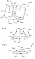
figure 2 illustrates a non-return valve for the air flow from a refrigerator compartment, with the membrane in the open configuration, according to the present invention, in a schematic perspective view; -
figures 3 and 4 illustrate the valve offigure 2 , respectively with the membrane in an open and a closed configuration, in a side view; -
figure 5 illustrates the valve offigure 2 , with the membrane in the closed configuration, in a view from above; -
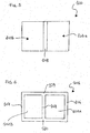
figure 6 illustrates a part (framework) of the valve offigure 2 , in a view from above. - With reference to the figures, the
number 1 denotes a refrigeration apparatus for cooling and storing, preferably per domestic applications. - The
refrigeration apparatus 1 comprises a refrigerator compartment 2 and afreezer compartment 3 for storing foods. - Preferably, the temperature of the refrigerator compartment 2 is comprised between about 0°C and 10°C. Preferably, the temperature of the
freezer compartment 3 is lower than about -15°C. - In the embodiment illustrated here, the refrigerator compartment 2 is positioned above the
freezer compartment 3. In an unillustrated variant embodiment, the refrigerator compartment 2 is positioned below thefreezer compartment 3. - The
refrigeration apparatus 1 comprises a means 4 for cooling the air intended for the refrigeration of the refrigerator compartment 2 and ameans 5 for moving the refrigerated air. For example, the cooling means 4 comprises a refrigeration circuit of a known type, in which a refrigerant fluid circulates. - Preferably, the
means 5 for moving the refrigerated air consists in a fan which, on being activated, conveys the air to aconduit 6. - In particular, the
conduit 6 extends from the cooling means 4 to the refrigerator compartment 2. - In this context, the flow of refrigerated air that goes from the cooling means 4 to the refrigerator compartment 2 is called "direct flow" and is indicated in
figure 1 with the letter F1. The air flow from the refrigerator compartment 2 to the cooling means 4 is instead called "backflow" and is indicated infigure 1 with the letter F2. - Preferably, both the cooling means 4 for cooling the air and the
fan 5 are disposed in a chamber 8 adjacent to thefreezer compartment 3. - The chamber 8 is separated from the
freezer compartment 3 by means of a wall 9 having a plurality ofslits 10. Thefan 5, on being activated, also conveys air to thefreezer compartment 3 through theslits 10 of the dividing wall 9. - The
refrigeration apparatus 1 comprises anon-return valve 100 for the air flow from refrigerator compartment 2. In particular, thenon-return valve 100 is operatively active on theconduit 6 so as to prevent the backflow F2. Thenon-return valve 100 comprises aperimeter frame 101 delimiting anopening 102 for passage of the air flow and at least twomembranes 103a, 103b partially constrained to theperimeter frame 101. - The
perimeter frame 101 is applied transversely to theconduit 6, that is, on a section of theconduit 6. - The term membrane means a layer of flexible material, for example an elastic one. Preferably, the
membranes 103a, 103b of thenon-return valve 100 are made of a silicone material. In an alternative embodiment, themembranes 103a, 103b are made with a siliconized protective support and a coating film (for example, calendered plasticized PVC). - Preferably, each of the two
membranes 103a, 103b has afirst edge 104 constrained to theperimeter frame 101. In this manner, the twomembranes 103a, 103b can rotate between at least a closed configuration, wherein they jointly occlude theopening 102 so as to prevent the return of air (i.e. to prevent the backflow F2), and at least an open configuration, wherein a secondfree edge 105 of eachmembrane 103a, 103b is distanced from theopening 102 so as to enable the passage of air to the refrigerator compartment 2 (i.e. to enable the direct flow F1). - Originally, the
first edges 104 of eachmembrane 103a, 103b are constrained toopposite sections perimeter frame 101 in such a manner that in passing from the closed configuration to the open configuration, the twomembranes 103a, 103b complete rotations in opposite directions. - The
first edges 104 of the twomembranes 103a, 103b are constrained to theopposite sections - As can be seen in
figure 4 , when themembranes 103a, 103b are in the closed configuration, thesecond edges 105 are at the minimum distance. By contrast, when themembranes 103a, 103b are in the open configuration, thesecond edges 105 are distanced from each other, as can be seen infigure 3 . - In other words, when passing from the closed configuration to the open configuration and vice versa, the
membranes 103a, 103b act in the manner of hinged doors relative to theperimeter frame 101. - Preferably, the
perimeter frame 101 defines a substantiallyrectangular opening 102 so that theopposite sections first edges 104 of themembranes 103a, 103b are constrained, are parallel to each other and lie on opposite sides of this rectangle (seefigure 6 ). - Preferably, the
non-return valve 100 comprises acrosspiece 108 constrained to theperimeter frame 101 so as to divide theopening 102 into two parts. In this manner, one of the membranes (saidfirst membrane 103a) is associated with afirst part 102a of theopening 102, whilst the other membrane (called second membrane 103b) is associated with asecond part 102b of theopening 102. - When the
membranes 103a, 103b are in the closed configuration, thesecond edges 105 abut on thecrosspiece 108, thereby preventing the passage of air through theopening 102. - Preferably, the two
membranes 103a, 103b are equal in surface area. - In particular, the
crosspiece 108 divides the opening 102 into twosymmetrical parts - Preferably, the
crosspiece 108 and theperimeter frame 101 form a single structural framework for themembranes 103a, 103b. - In a further embodiment (not illustrated), the framework comprises a grid which divides the
opening 102 into a plurality of parts. For example, the grid has the shape of a cross and theopening 102 is divided into four parts. - The
perimeter frame 101 comprises two additionalopposite sections opposite sections opening 102 relative to the direct flow F1. Consequently, in the closed configuration themembranes 103a, 103b are inclined relative to the planar extension of theopening 102. For example, themembranes 103a, 103b are inclined by an angle of between 0° and 30° relative to the planar extension of theopening 102. - In other words, when viewed in cross section, each of the
additional sections crosspiece 108 is engaged. - The operation of the refrigeration apparatus comprising the non-return valve proposed here is described below.
- Let us consider the situation in which the
fan 5 is running, so that air is conveyed to theconduit 6. - On being subjected to the direct flow F1, the
membranes 103a, 103b are lifted. The direct flow F1 thus reaches the refrigerator compartment 2. - When the temperature reached in the refrigerator compartment 2 is sufficiently low, the
fan 5 is stopped and the direct flow F1 is interrupted. - The
membranes 103a, 103b take on the closed configuration (given the absence of the direct flow F1 which lifts them), so that they abut on thecrosspiece 108 and prevent the passage of the backflow F2 through theopening 102. - From the description made, the characteristics of the non-return valve for the air flow from a refrigerator compartment and the refrigeration apparatus comprising said valve, according to the present invention, appear clear, as do the advantages thereof.
- In the preferred embodiment, the structure with central symmetry (relative to the crosspiece) enables a direct flow that is substantially concentrated in the central zone of the opening, thus reducing pressure drops to a minimum.
- It should also be noted that when the membranes are subjected to the direct flow they are lifted relative to the planar extension of the opening. However, this lifting - though modest - does not influence the diversion of the flow thanks to the fact that the opening has a central symmetry.
- Finally, by virtue of the fact that the closed membranes are already inclined, the push necessary for opening them is further reduced.
Claims (10)
- Non-return valve (100) for the air flow from a refrigerator compartment (2), comprising:a perimeter frame (101) delimiting an opening (102) for passage of the air flow toward said refrigerator compartment (2);at least two membranes (103a, 103b), each of which has a first edge (104) constrained to said perimeter frame (101) in such a manner that said membranes (103a, 103b) can rotate between at least a closed configuration, wherein they jointly occlude said opening (102) so as to prevent the backflow of air, and at least an open configuration, wherein a second free edge (105) of each one of said membranes (103a, 103b) is distanced from said opening (102) so as to enable the passage of air to the refrigerator compartment (2),characterized in that the first edges (104) of each membrane (103a, 103b) are constrained to opposite sections (106, 107) of said perimeter frame (101) in such a manner that in passing from the closed configuration to the open configuration, the two membranes (103a, 103b) complete rotations in opposite directions.
- Non-return valve (100) according to claim 1, wherein said second edges (105) are at the minimum distance when the membranes (103, 103b) are in the closed configuration and they are distanced from each other when the membranes (103a, 103b) are in the open configuration.
- Non-return valve (100) according to claim 1 or 2, wherein said membranes (103a, 103b) act in the manner of hinged doors with respect to said perimeter frame (101).
- Non-return valve (100) according to any one of the preceding claims, wherein the opening (102) defined by said perimeter frame (101) is substantially rectangular in shape, so that said opposite sections (106, 107), to which the first edges (104) of said membranes (103a, 103b) are constrained, are parallel to each other and lie on opposite sides of this rectangle.
- Non-return valve (100) according to any one of the preceding claims, further comprising a crosspiece (108) constrained to said perimeter frame (101) so as to divide said opening (102) in two parts, in the closed configuration of said membranes (103a, 103b), the second edge (105) of each membrane (103a, 103b) abutting on said crosspiece (108).
- Non-return valve (100) according to claim 5, wherein said crosspiece (108) and said perimeter frame (101) are part of a single structural framework.
- Non-return valve (100) according to any one of the preceding claims, wherein said two membranes (103a, 103b) are equal in surface area.
- Non-return valve (100) according to any one of the preceding claims, wherein said perimeter frame (101) comprises two additional opposite sections (109, 110) that are shaped so as to be convex in a central zone of said opening (102), so that in the closed configuration, said membranes (103a, 103b) are inclined with respect to the planar extension of the opening (102).
- Refrigeration apparatus (1) comprising:a refrigerator compartment (2);means for cooling (4) air;a conduit (6) suitable for setting the air cooling means (4) and said refrigerator compartment (2) in fluid communication;movement means (5) for moving the refrigerated air and conveying it towards said conduit (6);a non-return valve (100) according to any one of the preceding claims, said non-return valve (100) being operatively active on said conduit (6) so as to block the flow of air from the refrigerator compartment (2) to said cooling means (4).
- Refrigeration apparatus (1) according to claim 9, wherein the perimeter frame (101) of said non-return valve (100) is applied transversely to said conduit (6).
Applications Claiming Priority (1)
| Application Number | Priority Date | Filing Date | Title |
|---|---|---|---|
| ITPR20140100 | 2014-12-23 |
Publications (1)
| Publication Number | Publication Date |
|---|---|
| EP3037751A1 true EP3037751A1 (en) | 2016-06-29 |
Family
ID=52574359
Family Applications (1)
| Application Number | Title | Priority Date | Filing Date |
|---|---|---|---|
| EP15200502.1A Withdrawn EP3037751A1 (en) | 2014-12-23 | 2015-12-16 | Non-return valve for the air flow from a refrigerator compartment and refrigeration apparatus comprising said valve |
Country Status (2)
| Country | Link |
|---|---|
| EP (1) | EP3037751A1 (en) |
| RU (1) | RU2015154958A (en) |
Cited By (2)
| Publication number | Priority date | Publication date | Assignee | Title |
|---|---|---|---|---|
| CN106885421A (en) * | 2017-03-31 | 2017-06-23 | 青岛海尔股份有限公司 | The air-cooled control method of wind cooling refrigerator |
| CN107062769A (en) * | 2017-03-31 | 2017-08-18 | 青岛海尔股份有限公司 | Wind cooling refrigerator |
Citations (7)
| Publication number | Priority date | Publication date | Assignee | Title |
|---|---|---|---|---|
| US2856956A (en) * | 1954-11-22 | 1958-10-21 | Smolensky Michael | Pneumatic check valve |
| JPS5164958U (en) * | 1974-11-19 | 1976-05-21 | ||
| JPH0694346A (en) * | 1992-09-16 | 1994-04-05 | Matsushita Refrig Co Ltd | Refrigerator |
| US6330891B1 (en) * | 1999-04-22 | 2001-12-18 | Kabushiki Kaisha Sankyo Seiki Seisakusho | Double-damper apparatus |
| US20040147219A1 (en) * | 2002-08-12 | 2004-07-29 | Sankyo Seiki Mfg. Co., Ltd. | Damper device |
| US20070245767A1 (en) * | 2006-04-25 | 2007-10-25 | Hide Hara | Resin molded product, damper device and manufacturing method for resin molded product |
| EP2090854A2 (en) | 2008-02-15 | 2009-08-19 | Indesit Company S.P.A. | Electric device for cooling and stooring foods |
-
2015
- 2015-12-16 EP EP15200502.1A patent/EP3037751A1/en not_active Withdrawn
- 2015-12-22 RU RU2015154958A patent/RU2015154958A/en not_active Application Discontinuation
Patent Citations (7)
| Publication number | Priority date | Publication date | Assignee | Title |
|---|---|---|---|---|
| US2856956A (en) * | 1954-11-22 | 1958-10-21 | Smolensky Michael | Pneumatic check valve |
| JPS5164958U (en) * | 1974-11-19 | 1976-05-21 | ||
| JPH0694346A (en) * | 1992-09-16 | 1994-04-05 | Matsushita Refrig Co Ltd | Refrigerator |
| US6330891B1 (en) * | 1999-04-22 | 2001-12-18 | Kabushiki Kaisha Sankyo Seiki Seisakusho | Double-damper apparatus |
| US20040147219A1 (en) * | 2002-08-12 | 2004-07-29 | Sankyo Seiki Mfg. Co., Ltd. | Damper device |
| US20070245767A1 (en) * | 2006-04-25 | 2007-10-25 | Hide Hara | Resin molded product, damper device and manufacturing method for resin molded product |
| EP2090854A2 (en) | 2008-02-15 | 2009-08-19 | Indesit Company S.P.A. | Electric device for cooling and stooring foods |
Cited By (2)
| Publication number | Priority date | Publication date | Assignee | Title |
|---|---|---|---|---|
| CN106885421A (en) * | 2017-03-31 | 2017-06-23 | 青岛海尔股份有限公司 | The air-cooled control method of wind cooling refrigerator |
| CN107062769A (en) * | 2017-03-31 | 2017-08-18 | 青岛海尔股份有限公司 | Wind cooling refrigerator |
Also Published As
| Publication number | Publication date |
|---|---|
| RU2015154958A (en) | 2017-06-27 |
Similar Documents
| Publication | Publication Date | Title |
|---|---|---|
| US9303917B2 (en) | Vegetable container for refrigerators and refrigerator having the same | |
| CN104913570B (en) | Wind cooling refrigerator | |
| US9366473B2 (en) | Refrigeration unit having a container | |
| EP2090854B1 (en) | Electric device for cooling and stooring foods | |
| EP2667124A3 (en) | Synchronous compartment temperature control and apparatus for refrigeration with reduced energy consumption | |
| EP2645018A3 (en) | Refrigeration and/or freezer device | |
| EP2938942B1 (en) | A cooling device | |
| JP6729009B2 (en) | Showcase | |
| KR101923475B1 (en) | A device protecting the over-degree of a vaccum for a vegetables container of a refrigerator and a vegetables container having it | |
| CN102483285A (en) | Channel closure for a meltwater channel of a refrigerator, meltwater channel of a refrigerator, and refrigerator | |
| JP6861336B2 (en) | refrigerator | |
| CN108139135B (en) | Domestic refrigeration appliance with refrigerated space, freezer space and pressure compensation valve | |
| CN208238376U (en) | refrigerator | |
| US10415870B2 (en) | Pressure relief facility for refrigeration appliances | |
| RU2015154958A (en) | Check valve for air flow from the refrigerating chamber and a refrigerating apparatus containing said valve | |
| JP2003329354A5 (en) | ||
| EP3006871A1 (en) | Refrigerator with a compartment storing removable food containers having a controlled environment | |
| JP7170353B2 (en) | refrigerator | |
| EP4224100A1 (en) | Refrigeration unit | |
| JP6391148B2 (en) | Air cooler and operation method thereof | |
| JP4536425B2 (en) | Refrigerated showcase | |
| KR20140070519A (en) | Refrigerator | |
| DE102016220973A1 (en) | Household appliance with an interior and an interior lighting | |
| KR20140086939A (en) | Refrigerator | |
| KR20140086941A (en) | Refrigerator |
Legal Events
| Date | Code | Title | Description |
|---|---|---|---|
| PUAI | Public reference made under article 153(3) epc to a published international application that has entered the european phase |
Free format text: ORIGINAL CODE: 0009012 |
|
| AK | Designated contracting states |
Kind code of ref document: A1 Designated state(s): AL AT BE BG CH CY CZ DE DK EE ES FI FR GB GR HR HU IE IS IT LI LT LU LV MC MK MT NL NO PL PT RO RS SE SI SK SM TR |
|
| AX | Request for extension of the european patent |
Extension state: BA ME |
|
| STAA | Information on the status of an ep patent application or granted ep patent |
Free format text: STATUS: REQUEST FOR EXAMINATION WAS MADE |
|
| 17P | Request for examination filed |
Effective date: 20161220 |
|
| RBV | Designated contracting states (corrected) |
Designated state(s): AL AT BE BG CH CY CZ DE DK EE ES FI FR GB GR HR HU IE IS IT LI LT LU LV MC MK MT NL NO PL PT RO RS SE SI SK SM TR |
|
| RAP1 | Party data changed (applicant data changed or rights of an application transferred) |
Owner name: WHIRLPOOL EMEA S.P.A |
|
| GRAP | Despatch of communication of intention to grant a patent |
Free format text: ORIGINAL CODE: EPIDOSNIGR1 |
|
| STAA | Information on the status of an ep patent application or granted ep patent |
Free format text: STATUS: GRANT OF PATENT IS INTENDED |
|
| RIC1 | Information provided on ipc code assigned before grant |
Ipc: F25D 17/04 20060101AFI20181108BHEP Ipc: F16K 15/03 20060101ALI20181108BHEP |
|
| INTG | Intention to grant announced |
Effective date: 20181126 |
|
| STAA | Information on the status of an ep patent application or granted ep patent |
Free format text: STATUS: THE APPLICATION IS DEEMED TO BE WITHDRAWN |
|
| 18D | Application deemed to be withdrawn |
Effective date: 20190409 |