EP2090854A2 - Electric device for cooling and stooring foods - Google Patents
Electric device for cooling and stooring foods Download PDFInfo
- Publication number
- EP2090854A2 EP2090854A2 EP08021910A EP08021910A EP2090854A2 EP 2090854 A2 EP2090854 A2 EP 2090854A2 EP 08021910 A EP08021910 A EP 08021910A EP 08021910 A EP08021910 A EP 08021910A EP 2090854 A2 EP2090854 A2 EP 2090854A2
- Authority
- EP
- European Patent Office
- Prior art keywords
- membrane
- mount
- compartment
- frame
- opening
- Prior art date
- Legal status (The legal status is an assumption and is not a legal conclusion. Google has not performed a legal analysis and makes no representation as to the accuracy of the status listed.)
- Granted
Links
Images



Classifications
-
- F—MECHANICAL ENGINEERING; LIGHTING; HEATING; WEAPONS; BLASTING
- F25—REFRIGERATION OR COOLING; COMBINED HEATING AND REFRIGERATION SYSTEMS; HEAT PUMP SYSTEMS; MANUFACTURE OR STORAGE OF ICE; LIQUEFACTION SOLIDIFICATION OF GASES
- F25D—REFRIGERATORS; COLD ROOMS; ICE-BOXES; COOLING OR FREEZING APPARATUS NOT OTHERWISE PROVIDED FOR
- F25D17/00—Arrangements for circulating cooling fluids; Arrangements for circulating gas, e.g. air, within refrigerated spaces
- F25D17/04—Arrangements for circulating cooling fluids; Arrangements for circulating gas, e.g. air, within refrigerated spaces for circulating air, e.g. by convection
- F25D17/06—Arrangements for circulating cooling fluids; Arrangements for circulating gas, e.g. air, within refrigerated spaces for circulating air, e.g. by convection by forced circulation
- F25D17/062—Arrangements for circulating cooling fluids; Arrangements for circulating gas, e.g. air, within refrigerated spaces for circulating air, e.g. by convection by forced circulation in household refrigerators
- F25D17/065—Arrangements for circulating cooling fluids; Arrangements for circulating gas, e.g. air, within refrigerated spaces for circulating air, e.g. by convection by forced circulation in household refrigerators with compartments at different temperatures
-
- F—MECHANICAL ENGINEERING; LIGHTING; HEATING; WEAPONS; BLASTING
- F16—ENGINEERING ELEMENTS AND UNITS; GENERAL MEASURES FOR PRODUCING AND MAINTAINING EFFECTIVE FUNCTIONING OF MACHINES OR INSTALLATIONS; THERMAL INSULATION IN GENERAL
- F16K—VALVES; TAPS; COCKS; ACTUATING-FLOATS; DEVICES FOR VENTING OR AERATING
- F16K15/00—Check valves
- F16K15/02—Check valves with guided rigid valve members
- F16K15/03—Check valves with guided rigid valve members with a hinged closure member or with a pivoted closure member
-
- F—MECHANICAL ENGINEERING; LIGHTING; HEATING; WEAPONS; BLASTING
- F16—ENGINEERING ELEMENTS AND UNITS; GENERAL MEASURES FOR PRODUCING AND MAINTAINING EFFECTIVE FUNCTIONING OF MACHINES OR INSTALLATIONS; THERMAL INSULATION IN GENERAL
- F16K—VALVES; TAPS; COCKS; ACTUATING-FLOATS; DEVICES FOR VENTING OR AERATING
- F16K15/00—Check valves
- F16K15/02—Check valves with guided rigid valve members
- F16K15/03—Check valves with guided rigid valve members with a hinged closure member or with a pivoted closure member
- F16K15/031—Check valves with guided rigid valve members with a hinged closure member or with a pivoted closure member the hinge being flexible
-
- F—MECHANICAL ENGINEERING; LIGHTING; HEATING; WEAPONS; BLASTING
- F16—ENGINEERING ELEMENTS AND UNITS; GENERAL MEASURES FOR PRODUCING AND MAINTAINING EFFECTIVE FUNCTIONING OF MACHINES OR INSTALLATIONS; THERMAL INSULATION IN GENERAL
- F16K—VALVES; TAPS; COCKS; ACTUATING-FLOATS; DEVICES FOR VENTING OR AERATING
- F16K15/00—Check valves
- F16K15/02—Check valves with guided rigid valve members
- F16K15/03—Check valves with guided rigid valve members with a hinged closure member or with a pivoted closure member
- F16K15/035—Check valves with guided rigid valve members with a hinged closure member or with a pivoted closure member with a plurality of valve members
-
- F—MECHANICAL ENGINEERING; LIGHTING; HEATING; WEAPONS; BLASTING
- F25—REFRIGERATION OR COOLING; COMBINED HEATING AND REFRIGERATION SYSTEMS; HEAT PUMP SYSTEMS; MANUFACTURE OR STORAGE OF ICE; LIQUEFACTION SOLIDIFICATION OF GASES
- F25D—REFRIGERATORS; COLD ROOMS; ICE-BOXES; COOLING OR FREEZING APPARATUS NOT OTHERWISE PROVIDED FOR
- F25D17/00—Arrangements for circulating cooling fluids; Arrangements for circulating gas, e.g. air, within refrigerated spaces
- F25D17/04—Arrangements for circulating cooling fluids; Arrangements for circulating gas, e.g. air, within refrigerated spaces for circulating air, e.g. by convection
- F25D17/042—Air treating means within refrigerated spaces
- F25D17/045—Air flow control arrangements
-
- F—MECHANICAL ENGINEERING; LIGHTING; HEATING; WEAPONS; BLASTING
- F25—REFRIGERATION OR COOLING; COMBINED HEATING AND REFRIGERATION SYSTEMS; HEAT PUMP SYSTEMS; MANUFACTURE OR STORAGE OF ICE; LIQUEFACTION SOLIDIFICATION OF GASES
- F25D—REFRIGERATORS; COLD ROOMS; ICE-BOXES; COOLING OR FREEZING APPARATUS NOT OTHERWISE PROVIDED FOR
- F25D2317/00—Details or arrangements for circulating cooling fluids; Details or arrangements for circulating gas, e.g. air, within refrigerated spaces, not provided for in other groups of this subclass
- F25D2317/06—Details or arrangements for circulating cooling fluids; Details or arrangements for circulating gas, e.g. air, within refrigerated spaces, not provided for in other groups of this subclass with forced air circulation
- F25D2317/066—Details or arrangements for circulating cooling fluids; Details or arrangements for circulating gas, e.g. air, within refrigerated spaces, not provided for in other groups of this subclass with forced air circulation characterised by the air supply
- F25D2317/0664—Details or arrangements for circulating cooling fluids; Details or arrangements for circulating gas, e.g. air, within refrigerated spaces, not provided for in other groups of this subclass with forced air circulation characterised by the air supply from the side
-
- F—MECHANICAL ENGINEERING; LIGHTING; HEATING; WEAPONS; BLASTING
- F25—REFRIGERATION OR COOLING; COMBINED HEATING AND REFRIGERATION SYSTEMS; HEAT PUMP SYSTEMS; MANUFACTURE OR STORAGE OF ICE; LIQUEFACTION SOLIDIFICATION OF GASES
- F25D—REFRIGERATORS; COLD ROOMS; ICE-BOXES; COOLING OR FREEZING APPARATUS NOT OTHERWISE PROVIDED FOR
- F25D2317/00—Details or arrangements for circulating cooling fluids; Details or arrangements for circulating gas, e.g. air, within refrigerated spaces, not provided for in other groups of this subclass
- F25D2317/06—Details or arrangements for circulating cooling fluids; Details or arrangements for circulating gas, e.g. air, within refrigerated spaces, not provided for in other groups of this subclass with forced air circulation
- F25D2317/066—Details or arrangements for circulating cooling fluids; Details or arrangements for circulating gas, e.g. air, within refrigerated spaces, not provided for in other groups of this subclass with forced air circulation characterised by the air supply
- F25D2317/0666—Details or arrangements for circulating cooling fluids; Details or arrangements for circulating gas, e.g. air, within refrigerated spaces, not provided for in other groups of this subclass with forced air circulation characterised by the air supply from the freezer
-
- F—MECHANICAL ENGINEERING; LIGHTING; HEATING; WEAPONS; BLASTING
- F25—REFRIGERATION OR COOLING; COMBINED HEATING AND REFRIGERATION SYSTEMS; HEAT PUMP SYSTEMS; MANUFACTURE OR STORAGE OF ICE; LIQUEFACTION SOLIDIFICATION OF GASES
- F25D—REFRIGERATORS; COLD ROOMS; ICE-BOXES; COOLING OR FREEZING APPARATUS NOT OTHERWISE PROVIDED FOR
- F25D2317/00—Details or arrangements for circulating cooling fluids; Details or arrangements for circulating gas, e.g. air, within refrigerated spaces, not provided for in other groups of this subclass
- F25D2317/06—Details or arrangements for circulating cooling fluids; Details or arrangements for circulating gas, e.g. air, within refrigerated spaces, not provided for in other groups of this subclass with forced air circulation
- F25D2317/067—Details or arrangements for circulating cooling fluids; Details or arrangements for circulating gas, e.g. air, within refrigerated spaces, not provided for in other groups of this subclass with forced air circulation characterised by air ducts
- F25D2317/0672—Outlet ducts
Definitions
- This invention relates to an electric device for cooling and storing foods, preferably for household use.
- these devices comprise fridge freezers, typically of the no-frost type, with two or more compartments, each designed to store foods in a different way at a different temperature.
- the term "fridge freezer” is used to denote a device having both a refrigerator compartment and a freezer compartment.
- the mount defines a passage forming part of the conduit, while the membrane comprises at least one first part that can move between a first position where it faces and is in contact with the mount in order to occlude the passage and a second position where part of it is spaced from the mount.
- the humid air in the refrigerator compartment tends to cause droplets of moisture to settle on the flat edge of the passage.
- the surface tension of the water trapped between the membrane and the flat edge may cause the mount and membrane to stick to each other. If the pressure exerted by the air is not high enough to overcome the force of the surface tension of the water, then the air flow produced by the fan cannot enter the refrigerator compartment. This leads to malfunctioning of the fridge freezer.
- This invention therefore has for an aim to overcome the above mentioned disadvantages by providing an electric device for cooling and storing foods and with reduced risk of malfunctions.
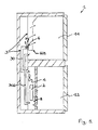
- Figure 1 is a schematic view of an electric device for cooling and storing foods according to the invention.
- Figure 2 is an interrupted perspective view, with some parts cut away in order to better illustrate others, of an electric device for cooling and storing foods according to the invention.
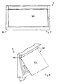
- Figures 3 and 4 show a component of the device of Figure 2 in two different working configurations.
- Figures 5 and 6 show two parts of the component of Figures 3 and 4 .
- Figures 7 and 8 show two alternative embodiments of the parts illustrated in Figures 5 and 6 .
- the numeral 1 denotes an electric device for cooling and storing foods, preferably for household use.
- the device 1 comprises:
- the shutoff valve 5 (usually known as “damper") is open to allow the first compartment 11 to be cooled.
- the device 1 comprises a second compartment 12 for storing foods.
- the first compartment 11 is a refrigerator compartment (where the temperatures are normally between 0 and 10°C) and the second compartment 12 is a freezer (where the temperatures are typically below -15°C).
- the first compartment 11 may be located either above or below the second compartment 12.
- the cooling means 2 are also used to cool the air in the second compartment 12 to better preserve the foods stored in it.
- the movement means 4 are also used to force the air from the cooling means 2 to the second compartment 12.
- the air flow movement means 4 are controlled according to the information from a first temperature sensor 8 which detects the temperature in the vicinity of the second compartment 12.
- the movement means 4 are switched on when the temperature detected by the first sensor 8 exceeds a first predetermined value.
- the cooling means 2 comprise a refrigerating circuit with a refrigerant fluid flowing in it. More specifically, the refrigerating circuit comprises an evaporator which allows heat exchange with the air used at least for cooling the first compartment 11.
- the refrigerating circuit also comprises a compressor which moves the refrigerant fluid inside the circuit. Preferably, the movement means 4 and the compressor are switched on simultaneously.
- the shutoff valve 5 is controlled according to the information from a second temperature sensor 7 located near the shutoff valve 5.
- the shutoff valve 5 is opened when the temperature detected by the second temperature sensor 7 is greater than a second predetermined value. Since the shutoff valve 5 and the movement means 4 are controlled, respectively, by the first and second sensors 8, 7 which are independent of each other, the shutoff valve 5 may be open (allowing air to flow through it) even when the movement means 4 are off (that is, when the fan is stopped).
- the device 1 comprises a non-return valve 6 operatively associated with the conduit 3.
- the conduit 3 comprises a tubular element 30 operatively interposed between the cooling means 2 and the non-return valve 6.
- the conduit 3 also comprises a channel 601 for distributing the air flow in the first compartment 11.
- the channel 601 is located downstream of the tubular element 30 relative to the direction of air flow from the cooling means 2 to the first compartment 11.
- the channel 601 can be fluid dynamically connected to the tubular element 30 and enables the air flow to be distributed at different heights in the first compartment 11.
- a recycling conduit 302 is provided for returning the air from the first compartment 11 to the cooling means 2.
- the non-return valve 6 has the important function of preventing the humid air in the first compartment 11 from finding its way into the tubular element 30 when the shutoff valve 5 is open and the movement means 4 are off.
- the tubular element 30 is designed solely to allow the passage of cold air from the cooling means 2 and this feature reduces the risk of the humid air condensing and freezing inside the tubular element 30.
- the non-return valve 6 may be located upstream or downstream of the shutoff valve 5.
- the non-return valve 6 comprises a membrane 60 and a mount 62 operatively connected. More specifically, the membrane 60 and the mount 62 are fixed to each other.
- the mount 62 comprises an opening 63 for the passage of the air, said opening 63 forming part of the conduit 3.
- the membrane 60 is flexible.
- the membrane 60 comprises at least one first part 61 that can move between a first position where it faces and is in contact with the mount 62 in order to totally occlude the opening 63 and a second position where at least a part of it is spaced from the mount 62.
- the first part 61 of the membrane 60 moves to the first position in contact with the mount 62 (see Figure 3 ). In this way, the opening 63 is occluded and the passage of air from the first compartment 11 to the cooling means 2 is obstructed, even if the shutoff valve 5 is off, that is, open.
- the mount 62 comprises at least one protuberance 67 which, when the first part 61 of the membrane 60 is in the first position, extends towards the first part 61 of the membrane 60, forming at least one zone of linear or point contact between the mount 62 and the first part 61 of the membrane 60.
- the first part 61 of the membrane 60 comprises at least one protuberance 67 which, when the first part 61 of the membrane 60 is in the first position, extends towards the mount 62, forming a zone of linear or point contact between the mount 62 and the first part 61 of the membrane 60.
- This embodiment is not preferable, however, because the membrane 60 is more difficult to make this way.
- the at least one protuberance 67 when the first part 61 of the membrane 60 is in the first position, reduces the overall zone of contact between the mount 62 and the first part 61 of the membrane 60 compared to a hypothetical situation where each protuberance allowing contact between the mount 62 and the first part 61 of the membrane 60 is absent. This minimizes adhesion caused by the surface tension of the condensed moisture droplets along the zone of contact between the mount 62 and the first part 61 of the membrane 60.
- linear zone of contact is used to mean a zone of contact extending mainly lengthwise and whose thickness is negligible compared to its length.
- zone of point contact is used to mean a zone of contact whose area is negligible compared to the total surface area of the first part 61 of the membrane 60 or of the mount 62.
- the membrane 60 is located just downstream of the mount 62 relative to the direction of air flow along the conduit 3 from the cooling means 4 to the first compartment 11.
- the mount 62 comprises a perimetric frame 65 that extends around and thus delimits the opening 63.
- the membrane 60 is connected in cantilever fashion to the mount 62 at one edge of the frame 65.
- the dashed lines in Figure 5 in particular indicate inserts 622 (hidden by the membrane 60) by which the membrane 60 is connected to the mount 62.
- Figure 6 shows housings 621 formed on the mount 62 and designed to accommodate the inserts 622. In this way, the air flowing in the conduit 3 from the cooling means 2 to the first compartment 11 can easily move the part of the membrane 60 furthest from the edge of it connected to the frame 65 away from the mount 62 and crosses to the other side.
- the above mentioned method by which the membrane 60 is joined to the mount 62 is a non-limiting example.
- the edge at which the membrane 60 is connected in cantilever fashion to the mount 62 is the upper edge 66 of the frame 65.
- the total zone of contact between the first part 61 of the membrane 60 and the frame 65 is substantially linear.
- the at least one protuberance 67 which forms at least one zone of linear contact between the first part 61 of the membrane 60 and the mount 62 when the first part 61 of the membrane 60 is in the first position, comprises or coincides with a relief portion 671 formed on a section of the frame 65.
- the protuberance 67 forms part of the mount 62.
- the relief portion 671 thus forms part of the frame 65.
- the relief portion 671 formed on a section of the frame 65 extends around the opening 63 along the edges of the frame 65 other than the one by which the first part 61 of the membrane 60 is connected in cantilever fashion.
- the relief portion 671 formed on a section of the frame 65 is tapered.
- the relief portion 671 forms a convex body which, when the first part 61 of the membrane 60 is in the first position, rests on a planar surface of the first part 61 of the membrane 60.
- the relief portion 671 formed on at least one section of the frame 65 is wedge-shaped and forms at the top a sharp edge 673 that defines at least one portion of the entire zone of contact between the frame 65 and the first part 61 of the membrane 60.
- the base edge 673 is formed at the intersection of the two planes made by the sides of the wedge of the protuberance 67.
- the top edge 673 of the relief portion 671 is parallel to the perimeter of the opening 63 of the frame 65.
- the top edge 673 constitutes the entire zone of contact between the frame 65 and the first part 61 of the membrane 60, when the latter is in the first position.
- the protuberance 67 of the at least one section of the mount 62 extends around the opening 63 along the edges of the frame 65 other than the one by which the first part 61 of the membrane 60 is connected in cantilever fashion.
- the protuberance 67 of the at least one section of the mount 62 extends uninterruptedly between a first and a second point along the perimeter of the opening 63 so that the opening 63 is sealed hermetically when closed.
- the mount 62 comprises a grille 69 which partly obstructs the opening 63 and which is formed on the inside of the area delimited by the frame 65.
- the grille 69 comprises a plurality of elongate members intersecting each other.
- the elongate members conveniently intersect each other at the centre of the opening 63.
- the grille 69 comprises a cross.
- the frame 65 has the shape of a quadrilateral and the ends of the cross are connected at least to the two bottom corners of the frame 65. This reduces the risk of the first part 61 of the membrane 60 getting stuck to the frame 65 compared to the case where the ends of the cross are connected to the points half way along the edges of the frame 65 (that is, in the embodiment where the cross is shaped like the graphical "+" sign).
- the ends of the cross are connected to all four corners of the frame 65 (in this case the cross is shaped like the letter "X” - see Figure 6 ) or the cross is shaped like an upturned “Y” connected at the two bottom corners of the frame 65 and along the upper edge of the frame 65 (see Figure 7 ).
- the grille 69 prevents the membrane 60 from getting stuck inside the opening 63 of the mount 62, with the risk of irreversibly occluding the flow of air and impairing the operation of the device 1.
- the entire zone of contact between the first part 61 of the membrane 60 and the grille 69 is substantially a zone of linear or point contact.
- the at least one protuberance 67 which forms at least one zone of linear or point contact between the first part 61 of the membrane 60 and the mount 62 when the first part 61 of the membrane 60 is in the first position, comprises or coincides with at least one relief portion 672 advantageously formed on at least one section of the grille 69.
- the at least one protuberance 67 forms part of the mount 62.
- the at least one protuberance 67 which forms at least one zone of linear or point contact between the first part 61 of the membrane 60 and the mount 62 when the first part 61 of the membrane 60 is in the first position, conveniently comprises or coincides with at least one relief portion 672 formed on the whole of the grille 69.
- the at least one protuberance 67 of the mount 60 comprises at least one relief portion 671 formed on the frame 65 and at least one relief portion 672 formed on the grille 69.
- the at least one relief portion 672 formed on at least one section of the grille 69 is tapered.
- the at least one relief portion 672 formed on at least one section of the grille 69 is wedge-shaped and forms at the top a sharp edge 674 that at least partly defines the zone of contact between the grille 69 and the first part 61 of the membrane 60.
- the top edge 674 extends along the line of principal extension of the elongate members constituting the grille 69.
- the grille 69 comprises a plurality of separate relief portions 672 which, when the first part 61 of the membrane 60 is in the first position, extend towards the first part 61 of the membrane 60, each of the relief portions 672 defining a respective zone of linear or point contact between the grille 69 and the first part 61 of the membrane 60.
- the relief portions 672 comprise tapered, pyramid-shaped elements, which may be truncated or rounded at the tip, in such a way that each substantially defines a zone of point contact.
- the first part 61 of the membrane 60 when in the first position, is in contact with the mount 62 and lies in a plane that makes a non-zero angle with a vertical plane substantially orthogonal to the direction of air flow through the opening 63.
- the force weight helps keep the membrane 60 in the first position at least for as long as a flow of air moves it.
- the membrane 60 may comprise reinforcement ribbing.
- This ribbing increases its rigidity, thus constituting an obstacle to opening and, in any case, under equal conditions of air flow, reducing the extent to which the membrane 60 opens because it is heavier. This reduces the probability that the first part 61 of the membrane 60 will be permanently deformed as a result of the repeated temperature variations it is subjected to. Indeed, if the first part 61 of the membrane 60 is deformed, the closure is no longer hermetically sealed and the operation of the device 1 is thus impaired.
- the at least one protuberance 67 is formed on the first part 61 of the membrane 60.
- the part of the membrane 60 on which the protuberance 67 is formed faces the mount 62.
- the protuberance 67 on the membrane 60 is in contact with the edges of the frame 65 to which the first part 61 of the membrane 60 is not connected in cantilever fashion, and/or with the grille 69.
- the non-return valve 6 comprises a plurality of membranes 60, 600, each designed to totally occlude a respective opening 63, 630 in the mount 62 (see Figures 7 and 8 ).
- each membrane 60, 600 is advantageously of the type described above.
- each opening 63, 630 designed to be obstructed by the respective membrane 60, 600 is delimited by a frame 65.
- Each of the frames 65 is of the type described above.
- the grille 69 in each opening 63, 630 is also of the type described above.
- these membranes 60, 600 might also be made in a single part having a connecting portion in common. This would enable the openings 63, 630 to be made smaller and, as a result, smaller air flow rates would be sufficient to open the first part 61 of the membrane 60, 600.
- each membrane 60, 600 reduces the risk its being deformed over time.
- the example shown in Figures 7 and 8 comprises two membranes 60, 600 occluding the respective openings 63, 630. A larger number of membranes and openings is, however, also imaginable.
- the membrane 60, 600 is made of silicone rubber, for example with a material commercially available under the name "Dynasil 1050".
- the membrane might be made with a siliconed protective backing with a cover film (for example, plasticized calendered PVC).
- the device 1 comprises, or coincides with, a fridge freezer 10.
- the invention achieves the important advantage of minimizing the risk of the membrane getting stuck in the mount as a result of droplets of moisture trapped between the membrane and the mount. Reducing the force of the surface tension to a minimum is achieved mainly by minimizing the overall zone of contact between the membrane and the mount.
Landscapes
- Engineering & Computer Science (AREA)
- General Engineering & Computer Science (AREA)
- Mechanical Engineering (AREA)
- Chemical & Material Sciences (AREA)
- Combustion & Propulsion (AREA)
- Physics & Mathematics (AREA)
- Thermal Sciences (AREA)
- Cold Air Circulating Systems And Constructional Details In Refrigerators (AREA)
Abstract
Description
- This invention relates to an electric device for cooling and storing foods, preferably for household use. For example, these devices comprise fridge freezers, typically of the no-frost type, with two or more compartments, each designed to store foods in a different way at a different temperature. The term "fridge freezer" is used to denote a device having both a refrigerator compartment and a freezer compartment.
- No frost fridge freezers are known which comprise:
- a refrigerator compartment for storing foods;
- a freezer compartment for storing the foods at lower temperatures;
- means for cooling the air in the refrigerator and freezer compartments;
- a conduit for placing the cooling means and the refrigerator compartment in fluid communication with each other;
- a fan for moving the air along the conduit from the cooling means to the refrigerator compartment;
- a shutoff valve for obstructing the conduit and which, when activated, prevents the fluid communication between the refrigerator compartment and the cooling means (this valve is usually referred to as "damper" in the jargon of the trade); the damper valve is usually open when cool air must be allowed into the refrigerator compartment in order to reduce the temperature of the compartment;
- a non-return valve operatively associated with the conduit, said non-return valve comprising a membrane and a supporting mount connected to each other.
- The mount defines a passage forming part of the conduit, while the membrane comprises at least one first part that can move between a first position where it faces and is in contact with the mount in order to occlude the passage and a second position where part of it is spaced from the mount. When the air flows along the conduit from the cooling means to the refrigerator compartment through the passage in the mount, it exerts pressure on the membrane. This causes the first part of the membrane to adopt the second position. When the pressure ceases, the membrane moves back to the first position in contact with the mount, thereby preventing the air from flowing from the refrigerator compartment to the cooling means through the non-return valve. The zone of contact between the membrane and the mount consists of at least one edge running round the passage, this edge being in the form of a flat surface.
- Fridge freezers of this kind, however, have several disadvantages.
- The humid air in the refrigerator compartment tends to cause droplets of moisture to settle on the flat edge of the passage. The surface tension of the water trapped between the membrane and the flat edge may cause the mount and membrane to stick to each other. If the pressure exerted by the air is not high enough to overcome the force of the surface tension of the water, then the air flow produced by the fan cannot enter the refrigerator compartment. This leads to malfunctioning of the fridge freezer.
- This invention therefore has for an aim to overcome the above mentioned disadvantages by providing an electric device for cooling and storing foods and with reduced risk of malfunctions.
- These aims and others, which are more apparent in the description which follows, are achieved, in accordance with this invention, by an electric device for cooling and storing foods having the structural and functional characteristics described in the independent claims herein. Alternative embodiments of the device are described in the dependent claims.
- Further features of the present invention are more apparent in the detailed description below, with reference to a preferred, non-limiting embodiment, as illustrated in the accompanying drawings.
-
Figure 1 is a schematic view of an electric device for cooling and storing foods according to the invention. -
Figure 2 is an interrupted perspective view, with some parts cut away in order to better illustrate others, of an electric device for cooling and storing foods according to the invention. -
Figures 3 and 4 show a component of the device ofFigure 2 in two different working configurations. -
Figures 5 and 6 show two parts of the component ofFigures 3 and 4 . -
Figures 7 and 8 show two alternative embodiments of the parts illustrated inFigures 5 and 6 . - With reference to the accompanying drawings, the numeral 1 denotes an electric device for cooling and storing foods, preferably for household use. The device 1 comprises:
- a
first compartment 11 for storing foods; - means 2 for cooling the air used for refrigerating the
first compartment 11; - a conduit 3 for placing the cooling means 2 and the
first compartment 11 in fluid communication with each other; - air movement means 4 which, when activated, force the air to flow from the cooling means 2 to the
first compartment 11; these movement means 4 may comprise a fan, for example; - a
shutoff valve 5 for obstructing the conduit 3 and which, when closed, prevents the fluid communication between thefirst compartment 11 and the cooling means 2. - The shutoff valve 5 (usually known as "damper") is open to allow the
first compartment 11 to be cooled. - Advantageously, the device 1 comprises a
second compartment 12 for storing foods. Preferably, thefirst compartment 11 is a refrigerator compartment (where the temperatures are normally between 0 and 10°C) and thesecond compartment 12 is a freezer (where the temperatures are typically below -15°C). Thefirst compartment 11 may be located either above or below thesecond compartment 12. - The cooling means 2 are also used to cool the air in the
second compartment 12 to better preserve the foods stored in it. In this regard, the movement means 4 are also used to force the air from the cooling means 2 to thesecond compartment 12. - The air flow movement means 4 are controlled according to the information from a
first temperature sensor 8 which detects the temperature in the vicinity of thesecond compartment 12. The movement means 4 are switched on when the temperature detected by thefirst sensor 8 exceeds a first predetermined value. The cooling means 2 comprise a refrigerating circuit with a refrigerant fluid flowing in it. More specifically, the refrigerating circuit comprises an evaporator which allows heat exchange with the air used at least for cooling thefirst compartment 11. The refrigerating circuit also comprises a compressor which moves the refrigerant fluid inside the circuit. Preferably, the movement means 4 and the compressor are switched on simultaneously. - The
shutoff valve 5 is controlled according to the information from a second temperature sensor 7 located near theshutoff valve 5. Theshutoff valve 5 is opened when the temperature detected by the second temperature sensor 7 is greater than a second predetermined value. Since theshutoff valve 5 and the movement means 4 are controlled, respectively, by the first andsecond sensors 8, 7 which are independent of each other, theshutoff valve 5 may be open (allowing air to flow through it) even when the movement means 4 are off (that is, when the fan is stopped). - The device 1 comprises a
non-return valve 6 operatively associated with the conduit 3. - The conduit 3 comprises a
tubular element 30 operatively interposed between the cooling means 2 and thenon-return valve 6. The conduit 3 also comprises achannel 601 for distributing the air flow in thefirst compartment 11. Thechannel 601 is located downstream of thetubular element 30 relative to the direction of air flow from the cooling means 2 to thefirst compartment 11. Thechannel 601 can be fluid dynamically connected to thetubular element 30 and enables the air flow to be distributed at different heights in thefirst compartment 11. As illustrated inFigure 1 , arecycling conduit 302 is provided for returning the air from thefirst compartment 11 to the cooling means 2. - The
non-return valve 6 has the important function of preventing the humid air in thefirst compartment 11 from finding its way into thetubular element 30 when theshutoff valve 5 is open and the movement means 4 are off. Thetubular element 30 is designed solely to allow the passage of cold air from the cooling means 2 and this feature reduces the risk of the humid air condensing and freezing inside thetubular element 30. - Relative to the direction of air flow from the cooling means 2 to the
first compartment 11, thenon-return valve 6 may be located upstream or downstream of theshutoff valve 5. - The
non-return valve 6 comprises amembrane 60 and amount 62 operatively connected. More specifically, themembrane 60 and themount 62 are fixed to each other. - The
mount 62 comprises anopening 63 for the passage of the air, said opening 63 forming part of the conduit 3. - Advantageously, the
membrane 60 is flexible. In particular, themembrane 60 comprises at least onefirst part 61 that can move between a first position where it faces and is in contact with themount 62 in order to totally occlude theopening 63 and a second position where at least a part of it is spaced from themount 62. - When the air flow produced by the movement means 4 moves along the conduit 3 from the cooling means 2 to the
first compartment 11, it goes through theopening 63 of themount 62, applying pressure on thefirst part 61 of themembrane 60 which thus adopts the second position (seeFigure 4 ). - When the air flow stops, the
first part 61 of themembrane 60 moves to the first position in contact with the mount 62 (seeFigure 3 ). In this way, theopening 63 is occluded and the passage of air from thefirst compartment 11 to the cooling means 2 is obstructed, even if theshutoff valve 5 is off, that is, open. - The
mount 62 comprises at least oneprotuberance 67 which, when thefirst part 61 of themembrane 60 is in the first position, extends towards thefirst part 61 of themembrane 60, forming at least one zone of linear or point contact between themount 62 and thefirst part 61 of themembrane 60. - In an alternative embodiment not illustrated, the
first part 61 of themembrane 60 comprises at least oneprotuberance 67 which, when thefirst part 61 of themembrane 60 is in the first position, extends towards themount 62, forming a zone of linear or point contact between themount 62 and thefirst part 61 of themembrane 60. This embodiment is not preferable, however, because themembrane 60 is more difficult to make this way. - Generally speaking, the at least one
protuberance 67, when thefirst part 61 of themembrane 60 is in the first position, reduces the overall zone of contact between themount 62 and thefirst part 61 of themembrane 60 compared to a hypothetical situation where each protuberance allowing contact between themount 62 and thefirst part 61 of themembrane 60 is absent. This minimizes adhesion caused by the surface tension of the condensed moisture droplets along the zone of contact between themount 62 and thefirst part 61 of themembrane 60. - The expression "linear zone of contact" is used to mean a zone of contact extending mainly lengthwise and whose thickness is negligible compared to its length. Similarly, the expression "zone of point contact" is used to mean a zone of contact whose area is negligible compared to the total surface area of the
first part 61 of themembrane 60 or of themount 62. - The
membrane 60 is located just downstream of themount 62 relative to the direction of air flow along the conduit 3 from the cooling means 4 to thefirst compartment 11. - The
mount 62 comprises aperimetric frame 65 that extends around and thus delimits theopening 63. - The
membrane 60 is connected in cantilever fashion to themount 62 at one edge of theframe 65. The dashed lines inFigure 5 in particular indicate inserts 622 (hidden by the membrane 60) by which themembrane 60 is connected to themount 62.Figure 6 , on the other hand, showshousings 621 formed on themount 62 and designed to accommodate theinserts 622. In this way, the air flowing in the conduit 3 from the cooling means 2 to thefirst compartment 11 can easily move the part of themembrane 60 furthest from the edge of it connected to theframe 65 away from themount 62 and crosses to the other side. The above mentioned method by which themembrane 60 is joined to themount 62 is a non-limiting example. - Relative to the physical vertical, the edge at which the
membrane 60 is connected in cantilever fashion to themount 62 is theupper edge 66 of theframe 65. Thus, when the air flow in the conduit 3 stops, the weight of thefirst part 61 of themembrane 60 enables thefirst part 61 of themembrane 60 to easily move from the second position back to the first position. - When the
first part 61 of themembrane 60 is in the first position, the total zone of contact between thefirst part 61 of themembrane 60 and theframe 65 is substantially linear. - The at least one
protuberance 67, which forms at least one zone of linear contact between thefirst part 61 of themembrane 60 and themount 62 when thefirst part 61 of themembrane 60 is in the first position, comprises or coincides with arelief portion 671 formed on a section of theframe 65. In this case, theprotuberance 67 forms part of themount 62. Therelief portion 671 thus forms part of theframe 65. - The
relief portion 671 formed on a section of theframe 65 extends around theopening 63 along the edges of theframe 65 other than the one by which thefirst part 61 of themembrane 60 is connected in cantilever fashion. - Advantageously, the
relief portion 671 formed on a section of theframe 65 is tapered. Advantageously, therelief portion 671 forms a convex body which, when thefirst part 61 of themembrane 60 is in the first position, rests on a planar surface of thefirst part 61 of themembrane 60. - As illustrated by way of example in
Figure 6 , therelief portion 671 formed on at least one section of theframe 65 is wedge-shaped and forms at the top asharp edge 673 that defines at least one portion of the entire zone of contact between theframe 65 and thefirst part 61 of themembrane 60. Advantageously, thebase edge 673 is formed at the intersection of the two planes made by the sides of the wedge of theprotuberance 67. Thetop edge 673 of therelief portion 671 is parallel to the perimeter of theopening 63 of theframe 65. - Advantageously, the
top edge 673 constitutes the entire zone of contact between theframe 65 and thefirst part 61 of themembrane 60, when the latter is in the first position. - The
protuberance 67 of the at least one section of themount 62 extends around theopening 63 along the edges of theframe 65 other than the one by which thefirst part 61 of themembrane 60 is connected in cantilever fashion. Advantageously, theprotuberance 67 of the at least one section of themount 62 extends uninterruptedly between a first and a second point along the perimeter of theopening 63 so that theopening 63 is sealed hermetically when closed. - The
mount 62 comprises agrille 69 which partly obstructs theopening 63 and which is formed on the inside of the area delimited by theframe 65. - The
grille 69 comprises a plurality of elongate members intersecting each other. The elongate members conveniently intersect each other at the centre of theopening 63. In particular, thegrille 69 comprises a cross. Advantageously, theframe 65 has the shape of a quadrilateral and the ends of the cross are connected at least to the two bottom corners of theframe 65. This reduces the risk of thefirst part 61 of themembrane 60 getting stuck to theframe 65 compared to the case where the ends of the cross are connected to the points half way along the edges of the frame 65 (that is, in the embodiment where the cross is shaped like the graphical "+" sign). In one particular embodiment, the ends of the cross are connected to all four corners of the frame 65 (in this case the cross is shaped like the letter "X" - seeFigure 6 ) or the cross is shaped like an upturned "Y" connected at the two bottom corners of theframe 65 and along the upper edge of the frame 65 (seeFigure 7 ). Thegrille 69 prevents themembrane 60 from getting stuck inside theopening 63 of themount 62, with the risk of irreversibly occluding the flow of air and impairing the operation of the device 1. - When the
first part 61 of themembrane 60 is in the first position, the entire zone of contact between thefirst part 61 of themembrane 60 and thegrille 69 is substantially a zone of linear or point contact. - The at least one
protuberance 67, which forms at least one zone of linear or point contact between thefirst part 61 of themembrane 60 and themount 62 when thefirst part 61 of themembrane 60 is in the first position, comprises or coincides with at least onerelief portion 672 advantageously formed on at least one section of thegrille 69. In this case, the at least oneprotuberance 67 forms part of themount 62. The at least oneprotuberance 67, which forms at least one zone of linear or point contact between thefirst part 61 of themembrane 60 and themount 62 when thefirst part 61 of themembrane 60 is in the first position, conveniently comprises or coincides with at least onerelief portion 672 formed on the whole of thegrille 69. - Advantageously, the at least one
protuberance 67 of themount 60 comprises at least onerelief portion 671 formed on theframe 65 and at least onerelief portion 672 formed on thegrille 69. - Advantageously, the at least one
relief portion 672 formed on at least one section of thegrille 69 is tapered. - The at least one
relief portion 672 formed on at least one section of thegrille 69 is wedge-shaped and forms at the top asharp edge 674 that at least partly defines the zone of contact between thegrille 69 and thefirst part 61 of themembrane 60. Thetop edge 674 extends along the line of principal extension of the elongate members constituting thegrille 69. - Advantageously, the
grille 69 comprises a plurality ofseparate relief portions 672 which, when thefirst part 61 of themembrane 60 is in the first position, extend towards thefirst part 61 of themembrane 60, each of therelief portions 672 defining a respective zone of linear or point contact between thegrille 69 and thefirst part 61 of themembrane 60. Advantageously, therelief portions 672 comprise tapered, pyramid-shaped elements, which may be truncated or rounded at the tip, in such a way that each substantially defines a zone of point contact. - As illustrated by way of non-limiting example in
Figure 3 , thefirst part 61 of themembrane 60, when in the first position, is in contact with themount 62 and lies in a plane that makes a non-zero angle with a vertical plane substantially orthogonal to the direction of air flow through theopening 63. In this way, the force weight helps keep themembrane 60 in the first position at least for as long as a flow of air moves it. - In an embodiment not illustrated the
membrane 60 may comprise reinforcement ribbing. This ribbing increases its rigidity, thus constituting an obstacle to opening and, in any case, under equal conditions of air flow, reducing the extent to which themembrane 60 opens because it is heavier. This reduces the probability that thefirst part 61 of themembrane 60 will be permanently deformed as a result of the repeated temperature variations it is subjected to. Indeed, if thefirst part 61 of themembrane 60 is deformed, the closure is no longer hermetically sealed and the operation of the device 1 is thus impaired. - Reference is now made to the embodiment not illustrated where the at least one
protuberance 67 is formed on thefirst part 61 of themembrane 60. When thefirst part 61 of themembrane 60 is in the first position, the part of themembrane 60 on which theprotuberance 67 is formed faces themount 62. Advantageously, theprotuberance 67 on themembrane 60 is in contact with the edges of theframe 65 to which thefirst part 61 of themembrane 60 is not connected in cantilever fashion, and/or with thegrille 69. - In one particular embodiment, the
non-return valve 6 comprises a plurality ofmembranes 60, 600, each designed to totally occlude arespective opening Figures 7 and 8 ). In this embodiment, eachmembrane 60, 600 is advantageously of the type described above. Similarly, eachopening respective membrane 60, 600 is delimited by aframe 65. Each of theframes 65 is of the type described above. Thegrille 69 in eachopening membranes 60, 600, thesemembranes 60, 600 might also be made in a single part having a connecting portion in common. This would enable theopenings first part 61 of themembrane 60, 600. - Thus, damage to one of the
membranes 60, 600 would not impair the operation of the entirenon-return valve 6. - Moreover, reducing the surface area of each
membrane 60, 600 reduces the risk its being deformed over time. The example shown inFigures 7 and 8 comprises twomembranes 60, 600 occluding therespective openings - Advantageously, the
membrane 60, 600 is made of silicone rubber, for example with a material commercially available under the name "Dynasil 1050". Alternatively, the membrane might be made with a siliconed protective backing with a cover film (for example, plasticized calendered PVC). - Advantageously, the device 1 comprises, or coincides with, a
fridge freezer 10. - The invention achieves the important advantage of minimizing the risk of the membrane getting stuck in the mount as a result of droplets of moisture trapped between the membrane and the mount. Reducing the force of the surface tension to a minimum is achieved mainly by minimizing the overall zone of contact between the membrane and the mount.
- It shall be understood that the invention described may be modified and adapted in several ways without departing from the scope of the inventive concept.
- Moreover, all the details of the invention may be substituted by other technically equivalent elements.
- In practice, all the materials used, as well as the dimensions, may be changed to meet specific needs.
Claims (15)
- An electric device for cooling and storing foods, preferably for household use, comprising:- a first compartment (11) for storing foods;- means (2) for cooling air used for refrigerating the first compartment (11);- a conduit (3) for placing the cooling means (2) and the first compartment (11) in fluid communication with each other;- air movement means (4) which, when activated, force the air to flow from the cooling means (2) to the first compartment (11);- a shutoff valve (5) for obstructing the conduit (3) and which, when closed, prevents the fluid communication between the first compartment (11) and the cooling means (2);- a non-return valve (6) operatively associated with the conduit (3), said non-return valve (6) comprising a membrane (60) and a mount (62) operatively connected to each other; the mount (62) comprising an opening (63) for the passage of the air, the opening (63) forming part of the conduit (3); the membrane (60) comprising at least one first part (61) that can move between a first position where it faces and is in contact with the mount (62) in order to occlude the opening (63) and a second position where it is at least partly spaced from the mount (62);
the air flow produced by the movement means (4) moving along the conduit (3) from the cooling means (2) to the first compartment (11) through the opening (63) of the mount (62) and applying pressure on the first part (61) of the membrane (60) causing the latter to adopt the second position; the first part (61) of the membrane (60) returning to the first position in contact with the mount (62), when the air flow stops, so as to obstruct the passage of the air from the first compartment (11) to the cooling means (2) even when the shutoff valve (5) is open;
the electric device being characterized in that the mount (62) or the first part (61) of the membrane (60) comprises at least one protuberance (67) which, when the first part (61) of the membrane (60) is in the first position, extends respectively towards the first part (61) of the membrane (60) or towards the mount (62), forming at least one zone of linear or point contact between the mount (62) and the first part (61) of the membrane (60). - The device according to claim 1, characterized in that the at least one protuberance (67), when the first part (61) of the membrane (60) is in the first position reduces the overall zone of contact between the mount (62) and the first part (61) of the membrane (60) compared to a hypothetical situation where each protuberance (67) allowing contact between the mount (60) and the first part (61) of the membrane (60) is absent.
- The device according to claim 1 or 2, characterized in that the membrane (60) is located immediately downstream of the mount (62) relative to the direction of air flow from the cooling means (4) to the first compartment (11).
- The device according to claim 1 or 2 or 3, characterized in that the mount (62) comprises a perimetric frame (65) that extends around and thus delimits the opening (63), the membrane (60) being connected in cantilever fashion to the mount (62) at one edge of the frame (65).
- The device according to claim 4, characterized in that relative to the physical vertical, the frame (65) comprises an upper edge (66) at which the membrane (60) is connected in cantilever fashion to the mount (62).
- The device according to claim 4 or 5, characterized in that the at least one protuberance (67), which forms at least one zone of linear contact between the first part (61) of the membrane (60) and the mount (62) when the first part (61) of the membrane (60) is in the first position, comprises, or coincides with, a relief portion (671) formed on a section of the frame (65).
- The device according to claim 6 when dependent on claim 4 or 5, characterized in that the relief portion (671) formed on a section of the frame (65) extends around the opening (63) along the edges of the frame (65) other than the one by which the first part (61) of the membrane (60) is connected in cantilever fashion.
- The device according to claim 6 or 7, characterized in that the relief portion (671) formed on a section of the frame (65) is tapered.
- The device according to any of the claims from 4 to 8, characterized in that the mount (62) comprises a grille (69) which partly obstructs the opening (63) and which is formed on the inside of the area delimited by the frame (65), the grille (69) comprising a plurality of elongate members intersecting each other.
- The device according to claim 9, characterized in that the at least one protuberance (67), which forms at least one zone of linear or point contact between the first part (61) of the membrane (60) and the mount (62) when the first part (61) of the membrane (60) is in the first position, comprises, or coincides with, at least one relief portion (672) formed on a section of the grille (69).
- The device according to claim 10, characterized in that the at least one relief portion (672) formed on a section of the grille (69) is tapered.
- The device according to any of the foregoing claims, characterized in that the first part (61) of the membrane (60), when in the first position, is in contact with the mount (62) and lies in a plane that makes a non-zero angle with a vertical plane substantially orthogonal to the direction of air flow through the opening (63).
- The device according to any of the foregoing claims, characterized in that the membrane (60) comprises reinforcement ribbing.
- The device according to any of the foregoing claims, characterized in that the non-return valve (6) comprises a plurality of membranes (60, 600), each designed to occlude a respective opening (63, 630) in the mount (62).
- The device according to any of the foregoing claims, characterized in that it comprises, or coincides with, a fridge freezer (10).
Applications Claiming Priority (1)
| Application Number | Priority Date | Filing Date | Title |
|---|---|---|---|
| IT000008A ITRN20080008A1 (en) | 2008-02-15 | 2008-02-15 | ELECTRIC DEVICE FOR COOLING AND CONSERVATION OF FOOD. |
Publications (3)
| Publication Number | Publication Date |
|---|---|
| EP2090854A2 true EP2090854A2 (en) | 2009-08-19 |
| EP2090854A3 EP2090854A3 (en) | 2015-09-23 |
| EP2090854B1 EP2090854B1 (en) | 2016-11-30 |
Family
ID=40291944
Family Applications (1)
| Application Number | Title | Priority Date | Filing Date |
|---|---|---|---|
| EP08021910.8A Not-in-force EP2090854B1 (en) | 2008-02-15 | 2008-12-17 | Electric device for cooling and stooring foods |
Country Status (3)
| Country | Link |
|---|---|
| EP (1) | EP2090854B1 (en) |
| IT (1) | ITRN20080008A1 (en) |
| RU (1) | RU2489654C2 (en) |
Cited By (6)
| Publication number | Priority date | Publication date | Assignee | Title |
|---|---|---|---|---|
| WO2015018645A1 (en) * | 2013-08-07 | 2015-02-12 | BSH Bosch und Siemens Hausgeräte GmbH | Refrigerator having an air-admission valve |
| CN105020963A (en) * | 2015-07-24 | 2015-11-04 | 合肥美的电冰箱有限公司 | Air duct assembly and refrigerator |
| EP3037751A1 (en) | 2014-12-23 | 2016-06-29 | Indesit Company S.p.A. | Non-return valve for the air flow from a refrigerator compartment and refrigeration apparatus comprising said valve |
| EP3037753A1 (en) | 2014-12-23 | 2016-06-29 | Indesit Company S.p.A. | Conduit for conveying air to a refrigerator compartment and refrigeration apparatus comprising said conduit |
| EP3040659A1 (en) * | 2014-12-30 | 2016-07-06 | Indesit Company S.p.A. | Refrigeration device |
| CN109983288A (en) * | 2016-11-21 | 2019-07-05 | Bsh家用电器有限公司 | Refrigeration appliances with storage compartments with optimum air humidity |
Family Cites Families (8)
| Publication number | Priority date | Publication date | Assignee | Title |
|---|---|---|---|---|
| SE322533B (en) * | 1967-12-11 | 1970-04-13 | Stal Refrigeration Ab | |
| US5156015A (en) * | 1990-12-20 | 1992-10-20 | Samsung Electronics Co., Ltd. | Method and apparatus for circulating cold air for an indirect-cooling type refrigerator |
| KR960001981B1 (en) * | 1992-09-23 | 1996-02-08 | 삼성전자주식회사 | Refrigerator |
| KR940009644A (en) * | 1992-10-09 | 1994-05-20 | 배순훈 | Refrigeration temperature control method and device |
| FR2786138B1 (en) * | 1998-07-28 | 2001-01-19 | Plastic Omnium Cie | NON-RETURN VALVE FOR FUEL TANK |
| WO2001023815A1 (en) * | 1999-09-28 | 2001-04-05 | Arçelik A.Ş. | Memory element controlled damper |
| ATE301811T1 (en) * | 2000-02-25 | 2005-08-15 | Liebherr Hausgeraete | DRAIN VALVE FOR A REFRIGERATOR AND/OR FREEZER |
| JP2005156108A (en) * | 2003-11-28 | 2005-06-16 | Matsushita Electric Ind Co Ltd | refrigerator |
-
2008
- 2008-02-15 IT IT000008A patent/ITRN20080008A1/en unknown
- 2008-12-17 EP EP08021910.8A patent/EP2090854B1/en not_active Not-in-force
-
2009
- 2009-02-13 RU RU2009105911/13A patent/RU2489654C2/en not_active IP Right Cessation
Cited By (6)
| Publication number | Priority date | Publication date | Assignee | Title |
|---|---|---|---|---|
| WO2015018645A1 (en) * | 2013-08-07 | 2015-02-12 | BSH Bosch und Siemens Hausgeräte GmbH | Refrigerator having an air-admission valve |
| EP3037751A1 (en) | 2014-12-23 | 2016-06-29 | Indesit Company S.p.A. | Non-return valve for the air flow from a refrigerator compartment and refrigeration apparatus comprising said valve |
| EP3037753A1 (en) | 2014-12-23 | 2016-06-29 | Indesit Company S.p.A. | Conduit for conveying air to a refrigerator compartment and refrigeration apparatus comprising said conduit |
| EP3040659A1 (en) * | 2014-12-30 | 2016-07-06 | Indesit Company S.p.A. | Refrigeration device |
| CN105020963A (en) * | 2015-07-24 | 2015-11-04 | 合肥美的电冰箱有限公司 | Air duct assembly and refrigerator |
| CN109983288A (en) * | 2016-11-21 | 2019-07-05 | Bsh家用电器有限公司 | Refrigeration appliances with storage compartments with optimum air humidity |
Also Published As
| Publication number | Publication date |
|---|---|
| RU2009105911A (en) | 2010-08-20 |
| EP2090854B1 (en) | 2016-11-30 |
| ITRN20080008A1 (en) | 2009-08-16 |
| RU2489654C2 (en) | 2013-08-10 |
| EP2090854A3 (en) | 2015-09-23 |
Similar Documents
| Publication | Publication Date | Title |
|---|---|---|
| EP2090854B1 (en) | Electric device for cooling and stooring foods | |
| CN111102772B (en) | Oil return system for low-temperature continuous heating, oil return control method and air conditioning equipment | |
| US9360247B2 (en) | Airtight container for refrigerator and refrigerator including the same | |
| US4299092A (en) | Energy conserving refrigerated merchandiser display case | |
| CN104215019B (en) | Vegetable container for refrigerator and refrigerator having same | |
| AU2006241811A1 (en) | Refrigerator | |
| EP3187800B1 (en) | A method of deciding when to terminate a defrosting cycle within a refrigerated container | |
| US20100212343A1 (en) | Refrigerated case with low frost operation | |
| US20120222436A1 (en) | Air Cooled Refrigerator, Method And System Of Controlling The Same | |
| US20070289323A1 (en) | Refrigerated case with low frost operation | |
| WO2016000750A1 (en) | Method for reducing ice formation in a cooling unit | |
| US20100269531A1 (en) | Cooling device | |
| KR20140000929A (en) | A device protecting the over-degree of a vaccum for a vegetables container of a refrigerator and a vegetables container having it | |
| US11209204B2 (en) | Heat pump system defrosting operations | |
| EP3037751A1 (en) | Non-return valve for the air flow from a refrigerator compartment and refrigeration apparatus comprising said valve | |
| US6058734A (en) | Refrigerator provided with cooled air bypass passages | |
| JP4545654B2 (en) | Cooling storage | |
| US20180080701A1 (en) | Pressure Relief Facility for Refrigeration Appliances | |
| CN220771578U (en) | Moisture permeable assembly and drawer cover plate | |
| KR970011689A (en) | Phase Separation Structure of Time Division Double Evaporator (CYCLE) Refrigerator | |
| CN119123744A (en) | Control method and device for refrigerator, refrigerator | |
| JP4428534B2 (en) | Cooling storage | |
| US20050091999A1 (en) | Method and apparatus for regulating power to a heating element surrounding a freezer door | |
| KR20100055121A (en) | Body for food storing apparatus | |
| JP7441644B2 (en) | refrigerator |
Legal Events
| Date | Code | Title | Description |
|---|---|---|---|
| PUAI | Public reference made under article 153(3) epc to a published international application that has entered the european phase |
Free format text: ORIGINAL CODE: 0009012 |
|
| AK | Designated contracting states |
Kind code of ref document: A2 Designated state(s): AT BE BG CH CY CZ DE DK EE ES FI FR GB GR HR HU IE IS IT LI LT LU LV MC MT NL NO PL PT RO SE SI SK TR |
|
| AX | Request for extension of the european patent |
Extension state: AL BA MK RS |
|
| PUAL | Search report despatched |
Free format text: ORIGINAL CODE: 0009013 |
|
| AK | Designated contracting states |
Kind code of ref document: A3 Designated state(s): AT BE BG CH CY CZ DE DK EE ES FI FR GB GR HR HU IE IS IT LI LT LU LV MC MT NL NO PL PT RO SE SI SK TR |
|
| AX | Request for extension of the european patent |
Extension state: AL BA MK RS |
|
| RIC1 | Information provided on ipc code assigned before grant |
Ipc: F16K 15/03 20060101ALI20150820BHEP Ipc: F25D 17/04 20060101AFI20150820BHEP |
|
| 17P | Request for examination filed |
Effective date: 20160323 |
|
| RBV | Designated contracting states (corrected) |
Designated state(s): AT BE BG CH CY CZ DE DK EE ES FI FR GB GR HR HU IE IS IT LI LT LU LV MC MT NL NO PL PT RO SE SI SK TR |
|
| AKX | Designation fees paid |
Designated state(s): AT BE BG CH CY CZ DE DK EE ES FI FR GB GR HR HU IE IS IT LI LT LU LV MC MT NL NO PL PT RO SE SI SK TR |
|
| AXX | Extension fees paid |
Extension state: MK Extension state: RS Extension state: BA Extension state: AL |
|
| GRAP | Despatch of communication of intention to grant a patent |
Free format text: ORIGINAL CODE: EPIDOSNIGR1 |
|
| INTG | Intention to grant announced |
Effective date: 20160920 |
|
| GRAS | Grant fee paid |
Free format text: ORIGINAL CODE: EPIDOSNIGR3 |
|
| GRAA | (expected) grant |
Free format text: ORIGINAL CODE: 0009210 |
|
| AK | Designated contracting states |
Kind code of ref document: B1 Designated state(s): AT BE BG CH CY CZ DE DK EE ES FI FR GB GR HR HU IE IS IT LI LT LU LV MC MT NL NO PL PT RO SE SI SK TR |
|
| REG | Reference to a national code |
Ref country code: CH Ref legal event code: EP Ref country code: GB Ref legal event code: FG4D |
|
| REG | Reference to a national code |
Ref country code: FR Ref legal event code: PLFP Year of fee payment: 9 Ref country code: AT Ref legal event code: REF Ref document number: 850185 Country of ref document: AT Kind code of ref document: T Effective date: 20161215 |
|
| REG | Reference to a national code |
Ref country code: IE Ref legal event code: FG4D |
|
| REG | Reference to a national code |
Ref country code: DE Ref legal event code: R096 Ref document number: 602008047601 Country of ref document: DE |
|
| PGFP | Annual fee paid to national office [announced via postgrant information from national office to epo] |
Ref country code: DE Payment date: 20161213 Year of fee payment: 9 Ref country code: GB Payment date: 20161214 Year of fee payment: 9 |
|
| RAP2 | Party data changed (patent owner data changed or rights of a patent transferred) |
Owner name: WHIRLPOOL EMEA S.P.A |
|
| PG25 | Lapsed in a contracting state [announced via postgrant information from national office to epo] |
Ref country code: LV Free format text: LAPSE BECAUSE OF FAILURE TO SUBMIT A TRANSLATION OF THE DESCRIPTION OR TO PAY THE FEE WITHIN THE PRESCRIBED TIME-LIMIT Effective date: 20161130 |
|
| PGFP | Annual fee paid to national office [announced via postgrant information from national office to epo] |
Ref country code: FR Payment date: 20161215 Year of fee payment: 9 |
|
| REG | Reference to a national code |
Ref country code: LT Ref legal event code: MG4D |
|
| REG | Reference to a national code |
Ref country code: NL Ref legal event code: MP Effective date: 20161130 |
|
| REG | Reference to a national code |
Ref country code: AT Ref legal event code: MK05 Ref document number: 850185 Country of ref document: AT Kind code of ref document: T Effective date: 20161130 |
|
| PG25 | Lapsed in a contracting state [announced via postgrant information from national office to epo] |
Ref country code: GR Free format text: LAPSE BECAUSE OF FAILURE TO SUBMIT A TRANSLATION OF THE DESCRIPTION OR TO PAY THE FEE WITHIN THE PRESCRIBED TIME-LIMIT Effective date: 20170301 Ref country code: LT Free format text: LAPSE BECAUSE OF FAILURE TO SUBMIT A TRANSLATION OF THE DESCRIPTION OR TO PAY THE FEE WITHIN THE PRESCRIBED TIME-LIMIT Effective date: 20161130 Ref country code: NO Free format text: LAPSE BECAUSE OF FAILURE TO SUBMIT A TRANSLATION OF THE DESCRIPTION OR TO PAY THE FEE WITHIN THE PRESCRIBED TIME-LIMIT Effective date: 20170228 Ref country code: SE Free format text: LAPSE BECAUSE OF FAILURE TO SUBMIT A TRANSLATION OF THE DESCRIPTION OR TO PAY THE FEE WITHIN THE PRESCRIBED TIME-LIMIT Effective date: 20161130 |
|
| PG25 | Lapsed in a contracting state [announced via postgrant information from national office to epo] |
Ref country code: BE Free format text: LAPSE BECAUSE OF NON-PAYMENT OF DUE FEES Effective date: 20161231 Ref country code: FI Free format text: LAPSE BECAUSE OF FAILURE TO SUBMIT A TRANSLATION OF THE DESCRIPTION OR TO PAY THE FEE WITHIN THE PRESCRIBED TIME-LIMIT Effective date: 20161130 Ref country code: ES Free format text: LAPSE BECAUSE OF FAILURE TO SUBMIT A TRANSLATION OF THE DESCRIPTION OR TO PAY THE FEE WITHIN THE PRESCRIBED TIME-LIMIT Effective date: 20161130 Ref country code: AT Free format text: LAPSE BECAUSE OF FAILURE TO SUBMIT A TRANSLATION OF THE DESCRIPTION OR TO PAY THE FEE WITHIN THE PRESCRIBED TIME-LIMIT Effective date: 20161130 Ref country code: HR Free format text: LAPSE BECAUSE OF FAILURE TO SUBMIT A TRANSLATION OF THE DESCRIPTION OR TO PAY THE FEE WITHIN THE PRESCRIBED TIME-LIMIT Effective date: 20161130 Ref country code: PT Free format text: LAPSE BECAUSE OF FAILURE TO SUBMIT A TRANSLATION OF THE DESCRIPTION OR TO PAY THE FEE WITHIN THE PRESCRIBED TIME-LIMIT Effective date: 20170330 Ref country code: PL Free format text: LAPSE BECAUSE OF FAILURE TO SUBMIT A TRANSLATION OF THE DESCRIPTION OR TO PAY THE FEE WITHIN THE PRESCRIBED TIME-LIMIT Effective date: 20161130 |
|
| PG25 | Lapsed in a contracting state [announced via postgrant information from national office to epo] |
Ref country code: NL Free format text: LAPSE BECAUSE OF FAILURE TO SUBMIT A TRANSLATION OF THE DESCRIPTION OR TO PAY THE FEE WITHIN THE PRESCRIBED TIME-LIMIT Effective date: 20161130 |
|
| PG25 | Lapsed in a contracting state [announced via postgrant information from national office to epo] |
Ref country code: DK Free format text: LAPSE BECAUSE OF FAILURE TO SUBMIT A TRANSLATION OF THE DESCRIPTION OR TO PAY THE FEE WITHIN THE PRESCRIBED TIME-LIMIT Effective date: 20161130 Ref country code: RO Free format text: LAPSE BECAUSE OF FAILURE TO SUBMIT A TRANSLATION OF THE DESCRIPTION OR TO PAY THE FEE WITHIN THE PRESCRIBED TIME-LIMIT Effective date: 20161130 Ref country code: SK Free format text: LAPSE BECAUSE OF FAILURE TO SUBMIT A TRANSLATION OF THE DESCRIPTION OR TO PAY THE FEE WITHIN THE PRESCRIBED TIME-LIMIT Effective date: 20161130 Ref country code: EE Free format text: LAPSE BECAUSE OF FAILURE TO SUBMIT A TRANSLATION OF THE DESCRIPTION OR TO PAY THE FEE WITHIN THE PRESCRIBED TIME-LIMIT Effective date: 20161130 Ref country code: CZ Free format text: LAPSE BECAUSE OF FAILURE TO SUBMIT A TRANSLATION OF THE DESCRIPTION OR TO PAY THE FEE WITHIN THE PRESCRIBED TIME-LIMIT Effective date: 20161130 |
|
| REG | Reference to a national code |
Ref country code: CH Ref legal event code: PL |
|
| PG25 | Lapsed in a contracting state [announced via postgrant information from national office to epo] |
Ref country code: BG Free format text: LAPSE BECAUSE OF FAILURE TO SUBMIT A TRANSLATION OF THE DESCRIPTION OR TO PAY THE FEE WITHIN THE PRESCRIBED TIME-LIMIT Effective date: 20170228 Ref country code: BE Free format text: LAPSE BECAUSE OF FAILURE TO SUBMIT A TRANSLATION OF THE DESCRIPTION OR TO PAY THE FEE WITHIN THE PRESCRIBED TIME-LIMIT Effective date: 20161130 |
|
| PGFP | Annual fee paid to national office [announced via postgrant information from national office to epo] |
Ref country code: IT Payment date: 20170323 Year of fee payment: 9 |
|
| REG | Reference to a national code |
Ref country code: DE Ref legal event code: R097 Ref document number: 602008047601 Country of ref document: DE |
|
| PG25 | Lapsed in a contracting state [announced via postgrant information from national office to epo] |
Ref country code: MC Free format text: LAPSE BECAUSE OF FAILURE TO SUBMIT A TRANSLATION OF THE DESCRIPTION OR TO PAY THE FEE WITHIN THE PRESCRIBED TIME-LIMIT Effective date: 20161130 |
|
| REG | Reference to a national code |
Ref country code: IE Ref legal event code: MM4A |
|
| PLBE | No opposition filed within time limit |
Free format text: ORIGINAL CODE: 0009261 |
|
| STAA | Information on the status of an ep patent application or granted ep patent |
Free format text: STATUS: NO OPPOSITION FILED WITHIN TIME LIMIT |
|
| PG25 | Lapsed in a contracting state [announced via postgrant information from national office to epo] |
Ref country code: LI Free format text: LAPSE BECAUSE OF NON-PAYMENT OF DUE FEES Effective date: 20161231 Ref country code: LU Free format text: LAPSE BECAUSE OF NON-PAYMENT OF DUE FEES Effective date: 20161217 Ref country code: CH Free format text: LAPSE BECAUSE OF NON-PAYMENT OF DUE FEES Effective date: 20161231 |
|
| 26N | No opposition filed |
Effective date: 20170831 |
|
| PG25 | Lapsed in a contracting state [announced via postgrant information from national office to epo] |
Ref country code: IE Free format text: LAPSE BECAUSE OF NON-PAYMENT OF DUE FEES Effective date: 20161217 Ref country code: SI Free format text: LAPSE BECAUSE OF FAILURE TO SUBMIT A TRANSLATION OF THE DESCRIPTION OR TO PAY THE FEE WITHIN THE PRESCRIBED TIME-LIMIT Effective date: 20161130 |
|
| PG25 | Lapsed in a contracting state [announced via postgrant information from national office to epo] |
Ref country code: CY Free format text: LAPSE BECAUSE OF FAILURE TO SUBMIT A TRANSLATION OF THE DESCRIPTION OR TO PAY THE FEE WITHIN THE PRESCRIBED TIME-LIMIT Effective date: 20161130 Ref country code: HU Free format text: LAPSE BECAUSE OF FAILURE TO SUBMIT A TRANSLATION OF THE DESCRIPTION OR TO PAY THE FEE WITHIN THE PRESCRIBED TIME-LIMIT; INVALID AB INITIO Effective date: 20081217 |
|
| PG25 | Lapsed in a contracting state [announced via postgrant information from national office to epo] |
Ref country code: TR Free format text: LAPSE BECAUSE OF FAILURE TO SUBMIT A TRANSLATION OF THE DESCRIPTION OR TO PAY THE FEE WITHIN THE PRESCRIBED TIME-LIMIT Effective date: 20161130 Ref country code: IS Free format text: LAPSE BECAUSE OF FAILURE TO SUBMIT A TRANSLATION OF THE DESCRIPTION OR TO PAY THE FEE WITHIN THE PRESCRIBED TIME-LIMIT Effective date: 20161130 |
|
| REG | Reference to a national code |
Ref country code: DE Ref legal event code: R119 Ref document number: 602008047601 Country of ref document: DE |
|
| GBPC | Gb: european patent ceased through non-payment of renewal fee |
Effective date: 20171217 |
|
| PG25 | Lapsed in a contracting state [announced via postgrant information from national office to epo] |
Ref country code: MT Free format text: LAPSE BECAUSE OF NON-PAYMENT OF DUE FEES Effective date: 20161217 |
|
| REG | Reference to a national code |
Ref country code: FR Ref legal event code: ST Effective date: 20180831 |
|
| PG25 | Lapsed in a contracting state [announced via postgrant information from national office to epo] |
Ref country code: DE Free format text: LAPSE BECAUSE OF NON-PAYMENT OF DUE FEES Effective date: 20180703 Ref country code: IT Free format text: LAPSE BECAUSE OF NON-PAYMENT OF DUE FEES Effective date: 20171217 Ref country code: FR Free format text: LAPSE BECAUSE OF NON-PAYMENT OF DUE FEES Effective date: 20180102 |
|
| PG25 | Lapsed in a contracting state [announced via postgrant information from national office to epo] |
Ref country code: GB Free format text: LAPSE BECAUSE OF NON-PAYMENT OF DUE FEES Effective date: 20171217 |