EP3037648A2 - Fuel cooling apparatus - Google Patents
Fuel cooling apparatus Download PDFInfo
- Publication number
- EP3037648A2 EP3037648A2 EP15197743.6A EP15197743A EP3037648A2 EP 3037648 A2 EP3037648 A2 EP 3037648A2 EP 15197743 A EP15197743 A EP 15197743A EP 3037648 A2 EP3037648 A2 EP 3037648A2
- Authority
- EP
- European Patent Office
- Prior art keywords
- fuel
- pipe
- region
- evaporation region
- circumferential surface
- Prior art date
- Legal status (The legal status is an assumption and is not a legal conclusion. Google has not performed a legal analysis and makes no representation as to the accuracy of the status listed.)
- Withdrawn
Links
- 239000000446 fuel Substances 0.000 title claims abstract description 275
- 238000001816 cooling Methods 0.000 title claims abstract description 96
- 238000001704 evaporation Methods 0.000 claims abstract description 57
- 230000008020 evaporation Effects 0.000 claims abstract description 57
- 238000009833 condensation Methods 0.000 claims abstract description 27
- 230000005494 condensation Effects 0.000 claims abstract description 27
- 239000002828 fuel tank Substances 0.000 description 9
- 239000007788 liquid Substances 0.000 description 8
- 238000010586 diagram Methods 0.000 description 4
- 238000002485 combustion reaction Methods 0.000 description 3
- 238000000034 method Methods 0.000 description 3
- 230000005855 radiation Effects 0.000 description 3
- RYGMFSIKBFXOCR-UHFFFAOYSA-N Copper Chemical compound [Cu] RYGMFSIKBFXOCR-UHFFFAOYSA-N 0.000 description 2
- 229910052802 copper Inorganic materials 0.000 description 2
- 239000010949 copper Substances 0.000 description 2
- 230000017525 heat dissipation Effects 0.000 description 2
- 238000010438 heat treatment Methods 0.000 description 2
- 239000011148 porous material Substances 0.000 description 2
- 230000004323 axial length Effects 0.000 description 1
- 239000003502 gasoline Substances 0.000 description 1
- 239000000463 material Substances 0.000 description 1
- 238000012986 modification Methods 0.000 description 1
- 230000004048 modification Effects 0.000 description 1
- 239000002245 particle Substances 0.000 description 1
- 230000003252 repetitive effect Effects 0.000 description 1
Images



Classifications
-
- F—MECHANICAL ENGINEERING; LIGHTING; HEATING; WEAPONS; BLASTING
- F02—COMBUSTION ENGINES; HOT-GAS OR COMBUSTION-PRODUCT ENGINE PLANTS
- F02M—SUPPLYING COMBUSTION ENGINES IN GENERAL WITH COMBUSTIBLE MIXTURES OR CONSTITUENTS THEREOF
- F02M31/00—Apparatus for thermally treating combustion-air, fuel, or fuel-air mixture
- F02M31/20—Apparatus for thermally treating combustion-air, fuel, or fuel-air mixture for cooling
-
- F—MECHANICAL ENGINEERING; LIGHTING; HEATING; WEAPONS; BLASTING
- F02—COMBUSTION ENGINES; HOT-GAS OR COMBUSTION-PRODUCT ENGINE PLANTS
- F02M—SUPPLYING COMBUSTION ENGINES IN GENERAL WITH COMBUSTIBLE MIXTURES OR CONSTITUENTS THEREOF
- F02M31/00—Apparatus for thermally treating combustion-air, fuel, or fuel-air mixture
- F02M31/005—Apparatus for thermally treating combustion-air, fuel, or fuel-air mixture using a heat-pipe
-
- F—MECHANICAL ENGINEERING; LIGHTING; HEATING; WEAPONS; BLASTING
- F28—HEAT EXCHANGE IN GENERAL
- F28D—HEAT-EXCHANGE APPARATUS, NOT PROVIDED FOR IN ANOTHER SUBCLASS, IN WHICH THE HEAT-EXCHANGE MEDIA DO NOT COME INTO DIRECT CONTACT
- F28D15/00—Heat-exchange apparatus with the intermediate heat-transfer medium in closed tubes passing into or through the conduit walls ; Heat-exchange apparatus employing intermediate heat-transfer medium or bodies
- F28D15/02—Heat-exchange apparatus with the intermediate heat-transfer medium in closed tubes passing into or through the conduit walls ; Heat-exchange apparatus employing intermediate heat-transfer medium or bodies in which the medium condenses and evaporates, e.g. heat pipes
- F28D15/0275—Arrangements for coupling heat-pipes together or with other structures, e.g. with base blocks; Heat pipe cores
-
- F—MECHANICAL ENGINEERING; LIGHTING; HEATING; WEAPONS; BLASTING
- F28—HEAT EXCHANGE IN GENERAL
- F28D—HEAT-EXCHANGE APPARATUS, NOT PROVIDED FOR IN ANOTHER SUBCLASS, IN WHICH THE HEAT-EXCHANGE MEDIA DO NOT COME INTO DIRECT CONTACT
- F28D7/00—Heat-exchange apparatus having stationary tubular conduit assemblies for both heat-exchange media, the media being in contact with different sides of a conduit wall
- F28D7/02—Heat-exchange apparatus having stationary tubular conduit assemblies for both heat-exchange media, the media being in contact with different sides of a conduit wall the conduits being helically coiled
- F28D7/026—Heat-exchange apparatus having stationary tubular conduit assemblies for both heat-exchange media, the media being in contact with different sides of a conduit wall the conduits being helically coiled the conduits of only one medium being helically coiled and formed by bent members, e.g. plates, the coils having a cylindrical configuration
-
- F—MECHANICAL ENGINEERING; LIGHTING; HEATING; WEAPONS; BLASTING
- F28—HEAT EXCHANGE IN GENERAL
- F28D—HEAT-EXCHANGE APPARATUS, NOT PROVIDED FOR IN ANOTHER SUBCLASS, IN WHICH THE HEAT-EXCHANGE MEDIA DO NOT COME INTO DIRECT CONTACT
- F28D7/00—Heat-exchange apparatus having stationary tubular conduit assemblies for both heat-exchange media, the media being in contact with different sides of a conduit wall
- F28D7/10—Heat-exchange apparatus having stationary tubular conduit assemblies for both heat-exchange media, the media being in contact with different sides of a conduit wall the conduits being arranged one within the other, e.g. concentrically
- F28D7/106—Heat-exchange apparatus having stationary tubular conduit assemblies for both heat-exchange media, the media being in contact with different sides of a conduit wall the conduits being arranged one within the other, e.g. concentrically consisting of two coaxial conduits or modules of two coaxial conduits
-
- F—MECHANICAL ENGINEERING; LIGHTING; HEATING; WEAPONS; BLASTING
- F28—HEAT EXCHANGE IN GENERAL
- F28F—DETAILS OF HEAT-EXCHANGE AND HEAT-TRANSFER APPARATUS, OF GENERAL APPLICATION
- F28F1/00—Tubular elements; Assemblies of tubular elements
- F28F1/10—Tubular elements and assemblies thereof with means for increasing heat-transfer area, e.g. with fins, with projections, with recesses
- F28F1/12—Tubular elements and assemblies thereof with means for increasing heat-transfer area, e.g. with fins, with projections, with recesses the means being only outside the tubular element
- F28F1/34—Tubular elements and assemblies thereof with means for increasing heat-transfer area, e.g. with fins, with projections, with recesses the means being only outside the tubular element and extending obliquely
- F28F1/36—Tubular elements and assemblies thereof with means for increasing heat-transfer area, e.g. with fins, with projections, with recesses the means being only outside the tubular element and extending obliquely the means being helically wound fins or wire spirals
-
- F—MECHANICAL ENGINEERING; LIGHTING; HEATING; WEAPONS; BLASTING
- F02—COMBUSTION ENGINES; HOT-GAS OR COMBUSTION-PRODUCT ENGINE PLANTS
- F02M—SUPPLYING COMBUSTION ENGINES IN GENERAL WITH COMBUSTIBLE MIXTURES OR CONSTITUENTS THEREOF
- F02M37/00—Apparatus or systems for feeding liquid fuel from storage containers to carburettors or fuel-injection apparatus; Arrangements for purifying liquid fuel specially adapted for, or arranged on, internal-combustion engines
- F02M37/0047—Layout or arrangement of systems for feeding fuel
- F02M37/0052—Details on the fuel return circuit; Arrangement of pressure regulators
-
- F—MECHANICAL ENGINEERING; LIGHTING; HEATING; WEAPONS; BLASTING
- F28—HEAT EXCHANGE IN GENERAL
- F28D—HEAT-EXCHANGE APPARATUS, NOT PROVIDED FOR IN ANOTHER SUBCLASS, IN WHICH THE HEAT-EXCHANGE MEDIA DO NOT COME INTO DIRECT CONTACT
- F28D15/00—Heat-exchange apparatus with the intermediate heat-transfer medium in closed tubes passing into or through the conduit walls ; Heat-exchange apparatus employing intermediate heat-transfer medium or bodies
- F28D15/02—Heat-exchange apparatus with the intermediate heat-transfer medium in closed tubes passing into or through the conduit walls ; Heat-exchange apparatus employing intermediate heat-transfer medium or bodies in which the medium condenses and evaporates, e.g. heat pipes
- F28D15/04—Heat-exchange apparatus with the intermediate heat-transfer medium in closed tubes passing into or through the conduit walls ; Heat-exchange apparatus employing intermediate heat-transfer medium or bodies in which the medium condenses and evaporates, e.g. heat pipes with tubes having a capillary structure
-
- F—MECHANICAL ENGINEERING; LIGHTING; HEATING; WEAPONS; BLASTING
- F28—HEAT EXCHANGE IN GENERAL
- F28D—HEAT-EXCHANGE APPARATUS, NOT PROVIDED FOR IN ANOTHER SUBCLASS, IN WHICH THE HEAT-EXCHANGE MEDIA DO NOT COME INTO DIRECT CONTACT
- F28D21/00—Heat-exchange apparatus not covered by any of the groups F28D1/00 - F28D20/00
- F28D2021/0019—Other heat exchangers for particular applications; Heat exchange systems not otherwise provided for
- F28D2021/008—Other heat exchangers for particular applications; Heat exchange systems not otherwise provided for for vehicles
- F28D2021/0087—Fuel coolers
-
- Y—GENERAL TAGGING OF NEW TECHNOLOGICAL DEVELOPMENTS; GENERAL TAGGING OF CROSS-SECTIONAL TECHNOLOGIES SPANNING OVER SEVERAL SECTIONS OF THE IPC; TECHNICAL SUBJECTS COVERED BY FORMER USPC CROSS-REFERENCE ART COLLECTIONS [XRACs] AND DIGESTS
- Y02—TECHNOLOGIES OR APPLICATIONS FOR MITIGATION OR ADAPTATION AGAINST CLIMATE CHANGE
- Y02T—CLIMATE CHANGE MITIGATION TECHNOLOGIES RELATED TO TRANSPORTATION
- Y02T10/00—Road transport of goods or passengers
- Y02T10/10—Internal combustion engine [ICE] based vehicles
- Y02T10/12—Improving ICE efficiencies
Definitions
- the present invention relates to a fuel cooling apparatus, and more particularly to a fuel cooling apparatus for cooling a fuel used for a diesel engine.
- a fuel In a diesel engine, a fuel should be injected into a combustion chamber under a high pressure. Therefore, the pressure of a fuel discharged from a pump should be set to be higher than that in a case of a gasoline engine. Accordingly, a diesel engine employs a high-pressure pump capable of increasing the pressure of a fuel and holding the fuel under a high pressure. When such a high-pressure pump is operated at a high speed, the temperature of the high-pressure pump increases. Thus, the fuel that returns to a fuel tank from a combustion chamber of an engine through a fuel return pipe may also be increased in temperature. The increased temperature of the fuel supplied to the engine causes a lowered density of the fuel, which reduces an output of the engine and lowers the fuel efficiency of the engine.
- JP-A 2011-127491 another method of cooling a fuel flowing through a fuel supply pipe and a fuel return pipe has been proposed in JP-A 2011-127491 .
- a fuel supply pipe and a fuel return pipe are extended to form a heat radiation part, which is exposed between the rearward of an engine cover and an engine hood. Wind generated at the time when a vehicle travels is directed to the exposed heat radiation part to cool a fuel flowing through the fuel supply pipe and the fuel return pipe.
- the fuel supply pipe or the fuel return pipe may be broken. In such a case, a fuel flowing inside of the fuel supply pipe or the fuel return pipe may leak out, resulting in a serial accident.
- U.S. Patent Publication 2013/0186076 discloses using a heat pipe to cool an exhaust manifold but is silent on using a heat pipe to cool a fuel flowing inside of a fuel supply pipe or a fuel return pipe.
- the present invention has been made in view of the above drawbacks in the prior art. It is, therefore, an object of the present invention to provide a fuel cooling apparatus capable of cooling a fuel at an optimal location with high cooling efficiency and safety.
- a fuel cooling apparatus capable of cooling a fuel at an optimal location with high cooling efficiency and safety.
- the fuel cooling apparatus is used for cooling a fuel flowing through a fuel pipe connected to an engine.
- the fuel cooling apparatus includes a fuel cooling pipe having an inner circumferential surface and a hermetically sealed space formed therein and a heat pipe allowing a working medium to flow therein.
- the heat pipe includes an evaporation region inserted into the hermetically sealed space of the fuel cooling pipe so that a fuel passage is formed between the evaporation region and the inner circumferential surface of the fuel cooling pipe.
- the evaporation region is configured to evaporate the working medium by heat exchange with a fuel flowing through the fuel passage.
- the heat pipe also includes a condensation region configured to condense the working medium evaporated at the evaporation region and an adiabatic region adiabatically connecting the evaporation region and the condensation region to each other.
- the condensation region is arranged outside of the fuel cooling pipe.
- the fuel cooling apparatus also has a fuel inlet port configured to introduce the fuel into the fuel passage of the fuel cooling pipe from the fuel pipe and a fuel outlet port configured to return the fuel that has flowed through the fuel passage in the fuel cooling pipe to the fuel pipe.
- the evaporation region of the heat pipe may have an outer circumferential surface and a ridge portion projecting from the outer circumferential surface toward the inner circumferential surface of the fuel cooling pipe.
- the ridge portion serves to guide the fuel flowing in the fuel passage.
- the ridge portion may be formed in a spiral manner along an axial direction of the evaporation region of the heat pipe.
- the fuel cooling pipe may have a ridge portion projecting from the inner circumferential surface thereof toward the evaporation region of the heat pipe.
- the ridge portion serves to guide the fuel flowing in the fuel passage.
- the ridge portion may be formed in a spiral manner along an axial direction of the fuel cooling pipe.
- the condensation region may have a plurality of fins.
- the fuel inlet port and the fuel outlet port may be connected to a fuel supply pipe that supplies the fuel to the engine.
- the fuel inlet port and the fuel outlet port may be connected to a fuel return pipe that returns the fuel to a fuel tank from the engine.
- FIGS. 1 to 6 Embodiments of a fuel cooling apparatus according to the present invention will be described in detail with reference to FIGS. 1 to 6 .
- the same components and corresponding components are denoted by the same reference numerals, and the repetitive explanation thereof will be omitted herein.
- FIG. 1 is a diagram schematically showing a fuel cooling apparatus 100 according to a first embodiment of the present invention and a diesel engine 10 using the fuel cooling apparatus 100.
- a fuel supply pipe 30 for supplying a fuel from a fuel tank 20 is connected to the diesel engine 10.
- a high-pressure pump 40 is provided in the middle of the fuel supply pipe 30.
- a fuel in the fuel tank 20 is supplied to the engine 10 by the high-pressure pump 40.
- a fuel return pipe 50 for returning an excess fuel to the fuel tank 20 is connected to the diesel engine 10. An excess fuel that has not been combusted in a combustion chamber of the engine 10 is returned to the fuel tank 20 through the fuel return pipe 50.
- the fuel cooling apparatus 100 according to the present embodiment is provided in the middle of the fuel return pipe 50.
- the fuel cooling apparatus 100 is provided on the fuel return pipe 50 in this embodiment, the present invention is not limited to this example.
- the fuel cooling apparatus 100 may be provided in the middle of the fuel supply pipe 30.
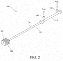
- FIG. 2 is a perspective view showing the fuel cooling apparatus 100.
- the fuel cooling apparatus 100 includes a fuel cooling pipe 110 having a hermitically sealed space therein and a heat pipe 120 having a first end inserted into the fuel cooling pipe 110.
- the fuel cooling apparatus 100 also includes a fuel inlet port 130 and a fuel outlet port 140 provided near opposite ends of the fuel cooling pipe 110.
- the fuel inlet port 130 is connected to the aforementioned fuel return pipe 50A extending from the engine 10 (see FIG. 1 ).
- the fuel outlet port 140 is connected to the fuel return pipe 50B connected to the fuel tank 20 (see FIG. 1 ).
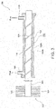
- FIG. 3 schematically illustrates the fuel cooling apparatus 100.
- the first end of the heat pipe 120 is inserted into the hermetically sealed space in the fuel cooling pipe 110.
- Working medium (not shown) flows inside of the heat pipe 120.
- the heat pipe 120 includes an evaporation region 122 operable to evaporate the working medium flowing inside of the heat pipe 120, a condensation region 124 operable to condense the working medium, and an adiabatic region 126 adiabatically connecting the evaporation region 122 and the condensation region 124 to each other.
- the evaporation region 122 of the heat pipe 120 is formed by a portion of the heat pipe 120 that is inserted into the hermetically sealed space of the fuel cooling pipe 110.
- a fuel passage 150 is formed between an outer circumferential surface 122A of the evaporation region 122 of the heat pipe 120 and an inner circumferential surface 110A of the fuel cooling pipe 110.
- This fuel passage 150 communicates with the fuel return pipe 50A connected to the fuel inlet port 130 and the fuel return pipe 50B connected to the fuel outlet port 140.
- a fuel is introduced into the fuel passage 150 from the fuel return pipe 50A through the fuel inlet port 130, delivered through the fuel passage 150 in an axial direction of the fuel cooling pipe 110, and then returned to the fuel return pipe 50B through the fuel outlet port 140.
- the condensation region 124 of the heat pipe 120 is located outside of the fuel cooling pipe 110 and provided on a second end of the heat pipe 120, which is an opposite side to the evaporation region 122.
- the condensation region 124 has a number of fins 160.
- the working vapor generated in the evaporation region 122 of the heat pipe 120 moves as latent heat through the adiabatic region 126 to the condensation region 124, where the working vapor is condensed into a working liquid by dissipation of heat from the fins 160.
- the fuel flowing through the fuel passage 150 can be cooled by transferring heat from the evaporation region 122 to the condensation region 124 of the heat pipe 120.
- FIG. 4 is a schematic cross-sectional view explanatory of an operation of the heat pipe 120.
- the heat pipe 120 includes a shell 170, in which a wicking layer 171 and a vapor space 173 are formed.
- the wicking layer 171 is formed inside of the shell 170, and the vapor space 173 is formed inside of the wicking layer 171.
- the shell 170 is made of a material having a high thermal conductivity, such as copper. Accordingly, thermal energy can effectively be absorbed into the working medium at the evaporation region 122. Furthermore, thermal energy can effectively be released from the working medium at the condensation region 124. In other words, the thermal energy of a high-temperature fuel flowing outside of the shell 170 can effectively be absorbed into the evaporation region 122, and the absorbed thermal energy can effectively be released from the condensation region 124.
- the adiabatic region 126 is located between the evaporation region 122 and the condensation region 124.
- the amount of heat transfer is substantially zero at the adiabatic region 126. In other words, the adiabatic region 126 does not absorb any thermal energy from surrounding regions or release any thermal energy into surrounding regions.
- the wicking layer 171 is formed of a porous material.
- the wicking layer 171 is formed of sintered copper particles. Capillary forces produced in such a porous material generate circulating forces of the working liquid within the heat pipe 120. Those circulating forces cause the working liquid to flow from the condensation region 124 to the evaporation region 122, i.e., from a low-temperature side to a high-temperature side in a direction indicated by the arrows 180. Heat received by the evaporation region 122 moves through heat conduction within the shell 170, the wicking layer 171, and a portion of the working liquid in the wicking layer 171.
- the working liquid evaporates at an interface between the working liquid and the vapor space 173, where the working vapor flows from the evaporation region 122 to the condensation region 124, i.e., from a high-temperature side to a low-temperature side in a direction indicated by the arrow 181.
- the thermal energy of a high-temperature fuel flowing through the fuel passage 150 in the fuel cooling pipe 110 is absorbed into the evaporation region 122 and released from the condensation region 124 by the working medium that changes its phase within the heat pipe 120.
- the fuel flowing through the fuel passage 150 is thus cooled.
- FIG. 5 is a perspective view showing the evaporation region 122 of the heat pipe 120, which is to be inserted into the hermetically sealed space of the fuel cooling pipe 110.
- the evaporation region 122 of the heat pipe 120 has a ridge portion 128 projecting from the outer circumferential surface 122A toward the inner circumferential surface 110A of the fuel cooling pipe 110.
- the ridge portion 128 is formed in a spiral manner along an axial direction of the evaporation region 122.
- the ridge portion 128 With the ridge portion 128 thus formed, the fuel is guided by the ridge portion 128 when it flows through the fuel passage 150 in the fuel cooling pipe 110. Therefore, a heating surface area is increased between the fuel and the evaporation region 122 of the heat pipe 120. Thus, the fuel can efficiently be cooled. It is preferable to bring the ridge portion 128 into contact with the inner circumferential surface 110A of the fuel cooling pipe 110. Nevertheless, the ridge portion 128 may not necessarily be brought into contact with the inner circumferential surface 110A of the fuel cooling pipe 110 as long as the fuel can be guided by the ridge portion 128.
- the fuel cooling pipe 110 may have an axial length of 300 mm and a thickness of 1.2 mm.
- the diameter of the inner circumferential surface 110A of the fuel cooling pipe 110 may be 15.7 mm.
- the diameter of the outer circumferential surface 122A of the evaporation region 122 of the heat pipe 120 may be 15 mm.
- the ridge portion 128 may have a height of 0.35 mm.
- a fuel is supplied to the fuel passage 150 in the fuel cooling pipe 110. Heat is exchanged between the fuel and the evaporation region 122 of the heat pipe 120. Therefore, the fuel can be cooled.
- the fuel flowing in the fuel return pipe 50 or the fuel supply pipe 30 can be cooled merely by connecting the fuel inlet port 130 and the fuel outlet port 140 to the fuel return pipe 50 or the fuel supply pipe 30. For example, if the fuel inlet port 130 and the fuel outlet port 140 are connected to the fuel return pipe 50 or the fuel supply pipe 30 near the engine 10, then a fuel flowing in the fuel pipe can be cooled within an engine room.
- the working medium evaporated within the evaporation region 122 by heat exchange with the fuel flowing through the fuel passage 150 is condensed in the condensation region 124, which is located outside of the fuel cooling pipe 110.
- the condensation region 124 can be located at any position independent of the evaporation region 122. Therefore, the condensation region 124 can be installed at a location having a high heat dissipation efficiency. Thus, the capability of cooling the fuel can be enhanced.
- the possibility of breakage upon application of external forces caused by collision of a vehicle or the like is increased.
- the fuel return pipe 50 and the fuel supply pipe 30 do not need to be extended, and the fuel inlet port 130 and the fuel outlet port 140 can be connected directly to the existing fuel return pipe 50 or fuel supply pipe 30. Accordingly, the possibility that the fuel return pipe 50 or the fuel supply pipe 30 is broken by collision of a vehicle or the like can be minimized. Thus, safety of the engine can be improved.
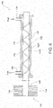
- FIG. 6 schematically illustrates a fuel cooling apparatus 200 according to a second embodiment of the present invention.
- a fuel cooling pipe 210 a fuel inlet port 130, and a fuel outlet port 140 are shown in cross-section as with FIG. 3 .
- the ridge portion 128 is formed on the outer circumferential surface 122A of the evaporation region 122 of the heat pipe 120.
- a ridge portion 218 is formed on an inner circumferential surface 210A of the fuel cooling pipe 210 so as to project from the inner circumferential surface 210A of the fuel cooling pipe 210 toward the outer circumferential surface 122A of the evaporation region 122 of the heat pipe 120.
- the ridge portion 218 is formed in a spiral manner along an axial direction of the fuel cooling pipe 210.
- the ridge portion 218 With the ridge portion 218 thus formed, the fuel is guided by the ridge portion 218 when it flows through the fuel passage 150 in the fuel cooling pipe 110. Therefore, a heating surface area is increased between the fuel and the evaporation region 122 of the heat pipe 120. Thus, the fuel can efficiently be cooled. It is preferable to bring the ridge portion 218 into contact with the outer circumferential surface 122A of the evaporation region 122 of the heat pipe 120. Nevertheless, the ridge portion 218 may not necessarily be brought into contact with the outer circumferential surface 122A of the evaporation region 122 of the heat pipe 120 as long as the fuel can be guided by the ridge portion 218.
- the condensation region for condensing the working medium can be located at any position independent of the evaporation region. Therefore, the condensation region can be installed at a location having a high heat dissipation efficiency. Thus, the capability of cooling the fuel can be enhanced. Moreover, and the fuel inlet port and the fuel outlet port can be connected directly to the existing fuel pipe, and the fuel pipe does not need to be extended. Accordingly, the possibility that the fuel pipe is broken by collision of a vehicle or the like can be minimized. Thus, safety of the engine can be improved.
Landscapes
- Engineering & Computer Science (AREA)
- Mechanical Engineering (AREA)
- General Engineering & Computer Science (AREA)
- Physics & Mathematics (AREA)
- Thermal Sciences (AREA)
- Chemical & Material Sciences (AREA)
- Combustion & Propulsion (AREA)
- Life Sciences & Earth Sciences (AREA)
- Sustainable Development (AREA)
- Geometry (AREA)
- Cooling, Air Intake And Gas Exhaust, And Fuel Tank Arrangements In Propulsion Units (AREA)
- Heat-Exchange Devices With Radiators And Conduit Assemblies (AREA)
Abstract
Description
- The present invention relates to a fuel cooling apparatus, and more particularly to a fuel cooling apparatus for cooling a fuel used for a diesel engine.
- In a diesel engine, a fuel should be injected into a combustion chamber under a high pressure. Therefore, the pressure of a fuel discharged from a pump should be set to be higher than that in a case of a gasoline engine. Accordingly, a diesel engine employs a high-pressure pump capable of increasing the pressure of a fuel and holding the fuel under a high pressure. When such a high-pressure pump is operated at a high speed, the temperature of the high-pressure pump increases. Thus, the fuel that returns to a fuel tank from a combustion chamber of an engine through a fuel return pipe may also be increased in temperature. The increased temperature of the fuel supplied to the engine causes a lowered density of the fuel, which reduces an output of the engine and lowers the fuel efficiency of the engine.
- For example, there has been proposed to provide fins at a portion of a fuel return pipe that is located near a fuel tank for cooling a fuel. See, e.g.,
JP-A H10-274109 - For example, another method of cooling a fuel flowing through a fuel supply pipe and a fuel return pipe has been proposed in
JP-A 2011-127491 - Furthermore,
U.S. Patent Publication 2013/0186076 discloses using a heat pipe to cool an exhaust manifold but is silent on using a heat pipe to cool a fuel flowing inside of a fuel supply pipe or a fuel return pipe. - The present invention has been made in view of the above drawbacks in the prior art. It is, therefore, an object of the present invention to provide a fuel cooling apparatus capable of cooling a fuel at an optimal location with high cooling efficiency and safety.
- According to an aspect of the present invention, there is provided a fuel cooling apparatus capable of cooling a fuel at an optimal location with high cooling efficiency and safety. The fuel cooling apparatus is used for cooling a fuel flowing through a fuel pipe connected to an engine. The fuel cooling apparatus includes a fuel cooling pipe having an inner circumferential surface and a hermetically sealed space formed therein and a heat pipe allowing a working medium to flow therein. The heat pipe includes an evaporation region inserted into the hermetically sealed space of the fuel cooling pipe so that a fuel passage is formed between the evaporation region and the inner circumferential surface of the fuel cooling pipe. The evaporation region is configured to evaporate the working medium by heat exchange with a fuel flowing through the fuel passage. The heat pipe also includes a condensation region configured to condense the working medium evaporated at the evaporation region and an adiabatic region adiabatically connecting the evaporation region and the condensation region to each other. The condensation region is arranged outside of the fuel cooling pipe. The fuel cooling apparatus also has a fuel inlet port configured to introduce the fuel into the fuel passage of the fuel cooling pipe from the fuel pipe and a fuel outlet port configured to return the fuel that has flowed through the fuel passage in the fuel cooling pipe to the fuel pipe.
- The evaporation region of the heat pipe may have an outer circumferential surface and a ridge portion projecting from the outer circumferential surface toward the inner circumferential surface of the fuel cooling pipe. The ridge portion serves to guide the fuel flowing in the fuel passage. In this case, the ridge portion may be formed in a spiral manner along an axial direction of the evaporation region of the heat pipe.
- Alternatively, the fuel cooling pipe may have a ridge portion projecting from the inner circumferential surface thereof toward the evaporation region of the heat pipe. The ridge portion serves to guide the fuel flowing in the fuel passage. In this case, the ridge portion may be formed in a spiral manner along an axial direction of the fuel cooling pipe.
- Moreover, the condensation region may have a plurality of fins. The fuel inlet port and the fuel outlet port may be connected to a fuel supply pipe that supplies the fuel to the engine. Alternatively, the fuel inlet port and the fuel outlet port may be connected to a fuel return pipe that returns the fuel to a fuel tank from the engine.
- The above and other objects, features, and advantages of the present invention will be apparent from the following description when taken in conjunction with the accompanying drawings which illustrate preferred embodiments of the present invention by way of example.
-
-
FIG. 1 is a diagram schematically showing a fuel cooling apparatus according to a first embodiment of the present invention and a diesel engine using the fuel cooling apparatus. -
FIG. 2 is a perspective view showing the fuel cooling apparatus shown inFIG. 1 . -
FIG. 3 is a diagram schematically illustrating the fuel cooling apparatus shown inFIG. 1 , with cross-sections of a fuel cooling pipe, a fuel inlet port, and a fuel outlet port of the fuel cooling apparatus. -
FIG. 4 is a schematic cross-sectional view explanatory of an operation of a heat pipe of the fuel cooling apparatus shown inFIG. 3 . -
FIG. 5 is a perspective view showing a portion of the heat pipe of the fuel cooling apparatus shown inFIG. 3 . -
FIG. 6 is a diagram schematically illustrating a fuel cooling apparatus according to a second embodiment of the present invention, with cross-sections of a fuel cooling pipe, a fuel inlet port, and a fuel outlet port of the fuel cooling apparatus. - Embodiments of a fuel cooling apparatus according to the present invention will be described in detail with reference to
FIGS. 1 to 6 . InFIGS. 1 to 6 , the same components and corresponding components are denoted by the same reference numerals, and the repetitive explanation thereof will be omitted herein. -
FIG. 1 is a diagram schematically showing afuel cooling apparatus 100 according to a first embodiment of the present invention and adiesel engine 10 using thefuel cooling apparatus 100. As shown inFIG. 1 , afuel supply pipe 30 for supplying a fuel from afuel tank 20 is connected to thediesel engine 10. A high-pressure pump 40 is provided in the middle of thefuel supply pipe 30. Thus, a fuel in thefuel tank 20 is supplied to theengine 10 by the high-pressure pump 40. Furthermore, afuel return pipe 50 for returning an excess fuel to thefuel tank 20 is connected to thediesel engine 10. An excess fuel that has not been combusted in a combustion chamber of theengine 10 is returned to thefuel tank 20 through thefuel return pipe 50. - The
fuel cooling apparatus 100 according to the present embodiment is provided in the middle of thefuel return pipe 50. Although thefuel cooling apparatus 100 is provided on thefuel return pipe 50 in this embodiment, the present invention is not limited to this example. For example, thefuel cooling apparatus 100 may be provided in the middle of thefuel supply pipe 30. -
FIG. 2 is a perspective view showing thefuel cooling apparatus 100. As shown inFIG. 2 , thefuel cooling apparatus 100 includes afuel cooling pipe 110 having a hermitically sealed space therein and aheat pipe 120 having a first end inserted into thefuel cooling pipe 110. Thefuel cooling apparatus 100 also includes afuel inlet port 130 and afuel outlet port 140 provided near opposite ends of thefuel cooling pipe 110. Thefuel inlet port 130 is connected to the aforementionedfuel return pipe 50A extending from the engine 10 (seeFIG. 1 ). Thefuel outlet port 140 is connected to thefuel return pipe 50B connected to the fuel tank 20 (seeFIG. 1 ). -
FIG. 3 schematically illustrates thefuel cooling apparatus 100. InFIG. 3 , only thefuel cooling pipe 110, thefuel inlet port 130, and thefuel outlet port 140 are shown in cross-section. As shown inFIG. 3 , the first end of theheat pipe 120 is inserted into the hermetically sealed space in thefuel cooling pipe 110. Working medium (not shown) flows inside of theheat pipe 120. Theheat pipe 120 includes anevaporation region 122 operable to evaporate the working medium flowing inside of theheat pipe 120, acondensation region 124 operable to condense the working medium, and anadiabatic region 126 adiabatically connecting theevaporation region 122 and thecondensation region 124 to each other. - The
evaporation region 122 of theheat pipe 120 is formed by a portion of theheat pipe 120 that is inserted into the hermetically sealed space of thefuel cooling pipe 110. As shown inFIG. 3 , afuel passage 150 is formed between an outercircumferential surface 122A of theevaporation region 122 of theheat pipe 120 and an innercircumferential surface 110A of thefuel cooling pipe 110. Thisfuel passage 150 communicates with thefuel return pipe 50A connected to thefuel inlet port 130 and thefuel return pipe 50B connected to thefuel outlet port 140. Thus, a fuel is introduced into thefuel passage 150 from thefuel return pipe 50A through thefuel inlet port 130, delivered through thefuel passage 150 in an axial direction of thefuel cooling pipe 110, and then returned to thefuel return pipe 50B through thefuel outlet port 140. - When a high-temperature fuel flowing through the
fuel passage 150 in thefuel cooling pipe 110 is brought into contact with the outercircumferential surface 122A of theevaporation region 122 of theheat pipe 120, then heat is exchanged between the high-temperature fuel and the working liquid flowing within theevaporation region 122. As a result, the working liquid flowing within theevaporation region 122 absorbs heat of the fuel and evaporates in theevaporation region 122. In this manner, the fuel flowing through thefuel passage 150 is cooled. - As shown in
FIG. 2 , thecondensation region 124 of theheat pipe 120 is located outside of thefuel cooling pipe 110 and provided on a second end of theheat pipe 120, which is an opposite side to theevaporation region 122. In the present embodiment, thecondensation region 124 has a number offins 160. - The working vapor generated in the
evaporation region 122 of theheat pipe 120 moves as latent heat through theadiabatic region 126 to thecondensation region 124, where the working vapor is condensed into a working liquid by dissipation of heat from thefins 160. Thus, the fuel flowing through thefuel passage 150 can be cooled by transferring heat from theevaporation region 122 to thecondensation region 124 of theheat pipe 120. -
FIG. 4 is a schematic cross-sectional view explanatory of an operation of theheat pipe 120. As shown inFIG. 4 , theheat pipe 120 includes ashell 170, in which awicking layer 171 and avapor space 173 are formed. As shown inFIG. 4 , thewicking layer 171 is formed inside of theshell 170, and thevapor space 173 is formed inside of thewicking layer 171. - For example, the
shell 170 is made of a material having a high thermal conductivity, such as copper. Accordingly, thermal energy can effectively be absorbed into the working medium at theevaporation region 122. Furthermore, thermal energy can effectively be released from the working medium at thecondensation region 124. In other words, the thermal energy of a high-temperature fuel flowing outside of theshell 170 can effectively be absorbed into theevaporation region 122, and the absorbed thermal energy can effectively be released from thecondensation region 124. - The
adiabatic region 126 is located between theevaporation region 122 and thecondensation region 124. The amount of heat transfer is substantially zero at theadiabatic region 126. In other words, theadiabatic region 126 does not absorb any thermal energy from surrounding regions or release any thermal energy into surrounding regions. - The
wicking layer 171 is formed of a porous material. For example, thewicking layer 171 is formed of sintered copper particles. Capillary forces produced in such a porous material generate circulating forces of the working liquid within theheat pipe 120. Those circulating forces cause the working liquid to flow from thecondensation region 124 to theevaporation region 122, i.e., from a low-temperature side to a high-temperature side in a direction indicated by thearrows 180. Heat received by theevaporation region 122 moves through heat conduction within theshell 170, thewicking layer 171, and a portion of the working liquid in thewicking layer 171. The working liquid evaporates at an interface between the working liquid and thevapor space 173, where the working vapor flows from theevaporation region 122 to thecondensation region 124, i.e., from a high-temperature side to a low-temperature side in a direction indicated by thearrow 181. - In this manner, the thermal energy of a high-temperature fuel flowing through the
fuel passage 150 in thefuel cooling pipe 110 is absorbed into theevaporation region 122 and released from thecondensation region 124 by the working medium that changes its phase within theheat pipe 120. The fuel flowing through thefuel passage 150 is thus cooled. -
FIG. 5 is a perspective view showing theevaporation region 122 of theheat pipe 120, which is to be inserted into the hermetically sealed space of thefuel cooling pipe 110. As shown inFIGS. 3 and5 , theevaporation region 122 of theheat pipe 120 has aridge portion 128 projecting from the outercircumferential surface 122A toward the innercircumferential surface 110A of thefuel cooling pipe 110. In the present embodiment, theridge portion 128 is formed in a spiral manner along an axial direction of theevaporation region 122. - With the
ridge portion 128 thus formed, the fuel is guided by theridge portion 128 when it flows through thefuel passage 150 in thefuel cooling pipe 110. Therefore, a heating surface area is increased between the fuel and theevaporation region 122 of theheat pipe 120. Thus, the fuel can efficiently be cooled. It is preferable to bring theridge portion 128 into contact with the innercircumferential surface 110A of thefuel cooling pipe 110. Nevertheless, theridge portion 128 may not necessarily be brought into contact with the innercircumferential surface 110A of thefuel cooling pipe 110 as long as the fuel can be guided by theridge portion 128. - For example, the
fuel cooling pipe 110 may have an axial length of 300 mm and a thickness of 1.2 mm. The diameter of the innercircumferential surface 110A of thefuel cooling pipe 110 may be 15.7 mm. The diameter of the outercircumferential surface 122A of theevaporation region 122 of theheat pipe 120 may be 15 mm. Theridge portion 128 may have a height of 0.35 mm. - According to the present embodiment, a fuel is supplied to the
fuel passage 150 in thefuel cooling pipe 110. Heat is exchanged between the fuel and theevaporation region 122 of theheat pipe 120. Therefore, the fuel can be cooled. Particularly, the fuel flowing in thefuel return pipe 50 or thefuel supply pipe 30 can be cooled merely by connecting thefuel inlet port 130 and thefuel outlet port 140 to thefuel return pipe 50 or thefuel supply pipe 30. For example, if thefuel inlet port 130 and thefuel outlet port 140 are connected to thefuel return pipe 50 or thefuel supply pipe 30 near theengine 10, then a fuel flowing in the fuel pipe can be cooled within an engine room. - As described above, the working medium evaporated within the
evaporation region 122 by heat exchange with the fuel flowing through thefuel passage 150 is condensed in thecondensation region 124, which is located outside of thefuel cooling pipe 110. Thecondensation region 124 can be located at any position independent of theevaporation region 122. Therefore, thecondensation region 124 can be installed at a location having a high heat dissipation efficiency. Thus, the capability of cooling the fuel can be enhanced. - Furthermore, if the
fuel return pipe 50 or thefuel supply pipe 30 is extended, the possibility of breakage upon application of external forces caused by collision of a vehicle or the like is increased. In contrast, according to the present embodiment, thefuel return pipe 50 and thefuel supply pipe 30 do not need to be extended, and thefuel inlet port 130 and thefuel outlet port 140 can be connected directly to the existingfuel return pipe 50 orfuel supply pipe 30. Accordingly, the possibility that thefuel return pipe 50 or thefuel supply pipe 30 is broken by collision of a vehicle or the like can be minimized. Thus, safety of the engine can be improved. -
FIG. 6 schematically illustrates afuel cooling apparatus 200 according to a second embodiment of the present invention. InFIG. 6 , only afuel cooling pipe 210, afuel inlet port 130, and afuel outlet port 140 are shown in cross-section as withFIG. 3 . In the aforementioned first embodiment, theridge portion 128 is formed on the outercircumferential surface 122A of theevaporation region 122 of theheat pipe 120. In the second embodiment, aridge portion 218 is formed on an innercircumferential surface 210A of thefuel cooling pipe 210 so as to project from the innercircumferential surface 210A of thefuel cooling pipe 210 toward the outercircumferential surface 122A of theevaporation region 122 of theheat pipe 120. In the present embodiment, theridge portion 218 is formed in a spiral manner along an axial direction of thefuel cooling pipe 210. - With the
ridge portion 218 thus formed, the fuel is guided by theridge portion 218 when it flows through thefuel passage 150 in thefuel cooling pipe 110. Therefore, a heating surface area is increased between the fuel and theevaporation region 122 of theheat pipe 120. Thus, the fuel can efficiently be cooled. It is preferable to bring theridge portion 218 into contact with the outercircumferential surface 122A of theevaporation region 122 of theheat pipe 120. Nevertheless, theridge portion 218 may not necessarily be brought into contact with the outercircumferential surface 122A of theevaporation region 122 of theheat pipe 120 as long as the fuel can be guided by theridge portion 218. - Thus, according to the aforementioned embodiments, when a fuel supplied into a fuel passage from a fuel inlet port is brought into contact with an evaporation region of a heat pipe, heat is exchanged between the high-temperature fuel and a working medium flowing within the evaporation region. As a result, the working medium flowing within the evaporation region absorbs heat of the fuel and evaporates in the evaporation region. Accordingly, the fuel flowing through the fuel passage is cooled. A fuel flowing in a fuel pipe can be cooled merely by connecting the fuel inlet port and the fuel outlet port to the fuel pipe. Therefore, the fuel can be cooled at an optimal location of the fuel pipe. Furthermore, the condensation region for condensing the working medium can be located at any position independent of the evaporation region. Therefore, the condensation region can be installed at a location having a high heat dissipation efficiency. Thus, the capability of cooling the fuel can be enhanced. Moreover, and the fuel inlet port and the fuel outlet port can be connected directly to the existing fuel pipe, and the fuel pipe does not need to be extended. Accordingly, the possibility that the fuel pipe is broken by collision of a vehicle or the like can be minimized. Thus, safety of the engine can be improved.
- Although certain preferred embodiments of the present invention have been shown and described in detail, it should be understood that various changes and modifications may be made therein without departing from the scope of the appended claims.
Claims (6)
- A fuel cooling apparatus for cooling a fuel flowing through a fuel pipe connected to an engine, the fuel cooling apparatus comprising:a fuel cooling pipe having an inner circumferential surface and a hermetically sealed space formed therein;a heat pipe allowing a working medium to flow therein, the heat pipe including:i) an evaporation region inserted into the hermetically sealed space of the fuel cooling pipe so that a fuel passage is formed between the evaporation region and the inner circumferential surface of the fuel cooling pipe, the evaporation region being configured to evaporate the working medium by heat exchange with a fuel flowing through the fuel passage,ii) a condensation region configured to condense the working medium evaporated at the evaporation region, the condensation region being arranged outside of the fuel cooling pipe, andiii) an adiabatic region adiabatically connecting the evaporation region and the condensation region to each other;a fuel inlet port configured to introduce the fuel into the fuel passage of the fuel cooling pipe from the fuel pipe; anda fuel outlet port configured to return the fuel that has flowed through the fuel passage in the fuel cooling pipe to the fuel pipe.
- The fuel cooling apparatus as recited in claim 1, wherein the evaporation region of the heat pipe has an outer circumferential surface and a ridge portion projecting from the outer circumferential surface toward the inner circumferential surface of the fuel cooling pipe, and the ridge portion is configured to guide the fuel flowing in the fuel passage.
- The fuel cooling apparatus as recited in claim 2, wherein the ridge portion is formed in a spiral manner along an axial direction of the evaporation region of the heat pipe.
- The fuel cooling apparatus as recited in claim 1, wherein the fuel cooling pipe has a ridge portion projecting from the inner circumferential surface thereof toward the evaporation region of the heat pipe, and the ridge portion is configured to guide the fuel flowing in the fuel passage.
- The fuel cooling apparatus as recited in claim 4, wherein the ridge portion is formed in a spiral manner along an axial direction of the fuel cooling pipe.
- The fuel cooling apparatus as recited in claim 1, wherein the condensation region has a plurality of fins.
Applications Claiming Priority (1)
| Application Number | Priority Date | Filing Date | Title |
|---|---|---|---|
| US14/562,013 US20160160814A1 (en) | 2014-12-05 | 2014-12-05 | Fuel cooling apparatus |
Publications (2)
| Publication Number | Publication Date |
|---|---|
| EP3037648A2 true EP3037648A2 (en) | 2016-06-29 |
| EP3037648A3 EP3037648A3 (en) | 2016-08-03 |
Family
ID=54782555
Family Applications (1)
| Application Number | Title | Priority Date | Filing Date |
|---|---|---|---|
| EP15197743.6A Withdrawn EP3037648A3 (en) | 2014-12-05 | 2015-12-03 | Fuel cooling apparatus |
Country Status (3)
| Country | Link |
|---|---|
| US (1) | US20160160814A1 (en) |
| EP (1) | EP3037648A3 (en) |
| JP (1) | JP2016109132A (en) |
Cited By (1)
| Publication number | Priority date | Publication date | Assignee | Title |
|---|---|---|---|---|
| FR3055185A1 (en) * | 2016-08-25 | 2018-03-02 | Nevinox | MILK TRANSFER FACILITY WITH THERMAL EXCHANGER |
Families Citing this family (1)
| Publication number | Priority date | Publication date | Assignee | Title |
|---|---|---|---|---|
| EP4563927A1 (en) * | 2023-11-30 | 2025-06-04 | Technische Universiteit Eindhoven | Heat pipe |
Citations (3)
| Publication number | Priority date | Publication date | Assignee | Title |
|---|---|---|---|---|
| JPH10274109A (en) | 1997-03-31 | 1998-10-13 | Nissan Diesel Motor Co Ltd | Fuel cooling device |
| JP2011127491A (en) | 2009-12-17 | 2011-06-30 | Suzuki Motor Corp | Fuel cooling device for diesel engine vehicle |
| US20130186076A1 (en) | 2012-01-19 | 2013-07-25 | Ford Global Technologies, Llc | Method to protect the exhaust manifold from overheating using heat pipe |
Family Cites Families (5)
| Publication number | Priority date | Publication date | Assignee | Title |
|---|---|---|---|---|
| EP0211419A3 (en) * | 1985-08-06 | 1987-05-20 | Bayerische Motoren Werke Aktiengesellschaft, Patentabteilung AJ-3 | Heat exchange device for an internal-combustion engine fuel |
| DE10234043A1 (en) * | 2002-07-26 | 2004-02-05 | Forschungszentrum Karlsruhe Gmbh | Microstructure apparatus for heating a fluid |
| US7654310B2 (en) * | 2006-01-30 | 2010-02-02 | Jaffe Limited | Loop heat pipe |
| JP6172950B2 (en) * | 2012-02-01 | 2017-08-02 | 株式会社Uacj | Double tube for heat exchanger |
| US20140026869A1 (en) * | 2012-07-27 | 2014-01-30 | Ford Global Technologies, Llc | Fuel delivery system including a heat pipe assembly |
-
2014
- 2014-12-05 US US14/562,013 patent/US20160160814A1/en not_active Abandoned
-
2015
- 2015-12-03 EP EP15197743.6A patent/EP3037648A3/en not_active Withdrawn
- 2015-12-03 JP JP2015236213A patent/JP2016109132A/en active Pending
Patent Citations (3)
| Publication number | Priority date | Publication date | Assignee | Title |
|---|---|---|---|---|
| JPH10274109A (en) | 1997-03-31 | 1998-10-13 | Nissan Diesel Motor Co Ltd | Fuel cooling device |
| JP2011127491A (en) | 2009-12-17 | 2011-06-30 | Suzuki Motor Corp | Fuel cooling device for diesel engine vehicle |
| US20130186076A1 (en) | 2012-01-19 | 2013-07-25 | Ford Global Technologies, Llc | Method to protect the exhaust manifold from overheating using heat pipe |
Cited By (1)
| Publication number | Priority date | Publication date | Assignee | Title |
|---|---|---|---|---|
| FR3055185A1 (en) * | 2016-08-25 | 2018-03-02 | Nevinox | MILK TRANSFER FACILITY WITH THERMAL EXCHANGER |
Also Published As
| Publication number | Publication date |
|---|---|
| US20160160814A1 (en) | 2016-06-09 |
| JP2016109132A (en) | 2016-06-20 |
| EP3037648A3 (en) | 2016-08-03 |
Similar Documents
| Publication | Publication Date | Title |
|---|---|---|
| JP4926889B2 (en) | Heat pipe based cooling system for turbine engines | |
| CN101349515B (en) | Exhaust heat recovery apparatus | |
| JP4578552B2 (en) | Cooling device and power conversion device | |
| US10842044B2 (en) | Cooling system in hybrid electric propulsion gas turbine engine | |
| JP5819221B2 (en) | Ship fuel supply system | |
| US8341950B2 (en) | Engine exhaust system having a thermoelectric conversion device and a heat pipe | |
| CN105121978A (en) | Co-fired absorption system generator | |
| JP2007002839A (en) | Method and apparatus for operating a gas turbine engine | |
| JP2007278623A (en) | Waste heat recovery device | |
| CN112055503A (en) | Immersion cooling device | |
| KR101393315B1 (en) | Cover of latent heat exchanger having cooling line | |
| JP2008534844A (en) | Fuel carrying member with heat pipe | |
| CN101358565B (en) | Exhaust heat recovery apparatus | |
| JP2005083251A (en) | Thermoelectric generator | |
| KR101361044B1 (en) | Thermoelectric generation apparatus for car | |
| JP5954103B2 (en) | Thermoelectric generator | |
| US20160160814A1 (en) | Fuel cooling apparatus | |
| CN107559074A (en) | Urea liquid injector module | |
| CN103380297A (en) | Power generator | |
| US7877990B2 (en) | Metering device and internal combustion engine having a metering device | |
| KR101280020B1 (en) | Heat-dissipating device for vehicle | |
| US20160334170A1 (en) | Motor vehicle heat exchanger system | |
| JP2018017204A (en) | Vehicle Rankine Cycle System | |
| CN201666179U (en) | Internal combustion engine provided with enhanced heat distribution system | |
| JP2015203340A (en) | Heat storage type fuel-heating device |
Legal Events
| Date | Code | Title | Description |
|---|---|---|---|
| PUAI | Public reference made under article 153(3) epc to a published international application that has entered the european phase |
Free format text: ORIGINAL CODE: 0009012 |
|
| 17P | Request for examination filed |
Effective date: 20151203 |
|
| AK | Designated contracting states |
Kind code of ref document: A2 Designated state(s): AL AT BE BG CH CY CZ DE DK EE ES FI FR GB GR HR HU IE IS IT LI LT LU LV MC MK MT NL NO PL PT RO RS SE SI SK SM TR |
|
| AX | Request for extension of the european patent |
Extension state: BA ME |
|
| PUAL | Search report despatched |
Free format text: ORIGINAL CODE: 0009013 |
|
| AK | Designated contracting states |
Kind code of ref document: A3 Designated state(s): AL AT BE BG CH CY CZ DE DK EE ES FI FR GB GR HR HU IE IS IT LI LT LU LV MC MK MT NL NO PL PT RO RS SE SI SK SM TR |
|
| AX | Request for extension of the european patent |
Extension state: BA ME |
|
| RIC1 | Information provided on ipc code assigned before grant |
Ipc: F28D 7/02 20060101ALI20160630BHEP Ipc: F02M 31/20 20060101AFI20160630BHEP |
|
| STAA | Information on the status of an ep patent application or granted ep patent |
Free format text: STATUS: THE APPLICATION IS DEEMED TO BE WITHDRAWN |
|
| 18D | Application deemed to be withdrawn |
Effective date: 20170204 |