EP3037590A1 - Method of preventing a rollback of a construction machine and apparatus for performing the same - Google Patents
Method of preventing a rollback of a construction machine and apparatus for performing the same Download PDFInfo
- Publication number
- EP3037590A1 EP3037590A1 EP15198147.9A EP15198147A EP3037590A1 EP 3037590 A1 EP3037590 A1 EP 3037590A1 EP 15198147 A EP15198147 A EP 15198147A EP 3037590 A1 EP3037590 A1 EP 3037590A1
- Authority
- EP
- European Patent Office
- Prior art keywords
- construction machine
- driving direction
- wheel
- rollback
- wheel excavator
- Prior art date
- Legal status (The legal status is an assumption and is not a legal conclusion. Google has not performed a legal analysis and makes no representation as to the accuracy of the status listed.)
- Granted
Links
- 238000010276 construction Methods 0.000 title claims abstract description 66
- 238000000034 method Methods 0.000 title claims abstract description 20
- 230000005540 biological transmission Effects 0.000 claims description 27
- 238000010586 diagram Methods 0.000 description 4
- 238000002513 implantation Methods 0.000 description 3
- 238000004519 manufacturing process Methods 0.000 description 2
- 239000007943 implant Substances 0.000 description 1
Images


Classifications
-
- B—PERFORMING OPERATIONS; TRANSPORTING
- B60—VEHICLES IN GENERAL
- B60T—VEHICLE BRAKE CONTROL SYSTEMS OR PARTS THEREOF; BRAKE CONTROL SYSTEMS OR PARTS THEREOF, IN GENERAL; ARRANGEMENT OF BRAKING ELEMENTS ON VEHICLES IN GENERAL; PORTABLE DEVICES FOR PREVENTING UNWANTED MOVEMENT OF VEHICLES; VEHICLE MODIFICATIONS TO FACILITATE COOLING OF BRAKES
- B60T7/00—Brake-action initiating means
- B60T7/12—Brake-action initiating means for automatic initiation; for initiation not subject to will of driver or passenger
-
- E—FIXED CONSTRUCTIONS
- E02—HYDRAULIC ENGINEERING; FOUNDATIONS; SOIL SHIFTING
- E02F—DREDGING; SOIL-SHIFTING
- E02F9/00—Component parts of dredgers or soil-shifting machines, not restricted to one of the kinds covered by groups E02F3/00 - E02F7/00
- E02F9/20—Drives; Control devices
- E02F9/22—Hydraulic or pneumatic drives
- E02F9/2253—Controlling the travelling speed of vehicles, e.g. adjusting travelling speed according to implement loads, control of hydrostatic transmission
-
- B—PERFORMING OPERATIONS; TRANSPORTING
- B60—VEHICLES IN GENERAL
- B60T—VEHICLE BRAKE CONTROL SYSTEMS OR PARTS THEREOF; BRAKE CONTROL SYSTEMS OR PARTS THEREOF, IN GENERAL; ARRANGEMENT OF BRAKING ELEMENTS ON VEHICLES IN GENERAL; PORTABLE DEVICES FOR PREVENTING UNWANTED MOVEMENT OF VEHICLES; VEHICLE MODIFICATIONS TO FACILITATE COOLING OF BRAKES
- B60T7/00—Brake-action initiating means
- B60T7/12—Brake-action initiating means for automatic initiation; for initiation not subject to will of driver or passenger
- B60T7/122—Brake-action initiating means for automatic initiation; for initiation not subject to will of driver or passenger for locking of reverse movement
-
- B—PERFORMING OPERATIONS; TRANSPORTING
- B60—VEHICLES IN GENERAL
- B60T—VEHICLE BRAKE CONTROL SYSTEMS OR PARTS THEREOF; BRAKE CONTROL SYSTEMS OR PARTS THEREOF, IN GENERAL; ARRANGEMENT OF BRAKING ELEMENTS ON VEHICLES IN GENERAL; PORTABLE DEVICES FOR PREVENTING UNWANTED MOVEMENT OF VEHICLES; VEHICLE MODIFICATIONS TO FACILITATE COOLING OF BRAKES
- B60T8/00—Arrangements for adjusting wheel-braking force to meet varying vehicular or ground-surface conditions, e.g. limiting or varying distribution of braking force
- B60T8/24—Arrangements for adjusting wheel-braking force to meet varying vehicular or ground-surface conditions, e.g. limiting or varying distribution of braking force responsive to vehicle inclination or change of direction, e.g. negotiating bends
-
- B—PERFORMING OPERATIONS; TRANSPORTING
- B60—VEHICLES IN GENERAL
- B60W—CONJOINT CONTROL OF VEHICLE SUB-UNITS OF DIFFERENT TYPE OR DIFFERENT FUNCTION; CONTROL SYSTEMS SPECIALLY ADAPTED FOR HYBRID VEHICLES; ROAD VEHICLE DRIVE CONTROL SYSTEMS FOR PURPOSES NOT RELATED TO THE CONTROL OF A PARTICULAR SUB-UNIT
- B60W10/00—Conjoint control of vehicle sub-units of different type or different function
- B60W10/18—Conjoint control of vehicle sub-units of different type or different function including control of braking systems
-
- B—PERFORMING OPERATIONS; TRANSPORTING
- B60—VEHICLES IN GENERAL
- B60W—CONJOINT CONTROL OF VEHICLE SUB-UNITS OF DIFFERENT TYPE OR DIFFERENT FUNCTION; CONTROL SYSTEMS SPECIALLY ADAPTED FOR HYBRID VEHICLES; ROAD VEHICLE DRIVE CONTROL SYSTEMS FOR PURPOSES NOT RELATED TO THE CONTROL OF A PARTICULAR SUB-UNIT
- B60W40/00—Estimation or calculation of non-directly measurable driving parameters for road vehicle drive control systems not related to the control of a particular sub unit, e.g. by using mathematical models
- B60W40/02—Estimation or calculation of non-directly measurable driving parameters for road vehicle drive control systems not related to the control of a particular sub unit, e.g. by using mathematical models related to ambient conditions
- B60W40/06—Road conditions
- B60W40/076—Slope angle of the road
-
- E—FIXED CONSTRUCTIONS
- E02—HYDRAULIC ENGINEERING; FOUNDATIONS; SOIL SHIFTING
- E02F—DREDGING; SOIL-SHIFTING
- E02F9/00—Component parts of dredgers or soil-shifting machines, not restricted to one of the kinds covered by groups E02F3/00 - E02F7/00
- E02F9/20—Drives; Control devices
- E02F9/22—Hydraulic or pneumatic drives
- E02F9/226—Safety arrangements, e.g. hydraulic driven fans, preventing cavitation, leakage, overheating
-
- E—FIXED CONSTRUCTIONS
- E02—HYDRAULIC ENGINEERING; FOUNDATIONS; SOIL SHIFTING
- E02F—DREDGING; SOIL-SHIFTING
- E02F9/00—Component parts of dredgers or soil-shifting machines, not restricted to one of the kinds covered by groups E02F3/00 - E02F7/00
- E02F9/26—Indicating devices
- E02F9/264—Sensors and their calibration for indicating the position of the work tool
- E02F9/265—Sensors and their calibration for indicating the position of the work tool with follow-up actions (e.g. control signals sent to actuate the work tool)
-
- B—PERFORMING OPERATIONS; TRANSPORTING
- B60—VEHICLES IN GENERAL
- B60W—CONJOINT CONTROL OF VEHICLE SUB-UNITS OF DIFFERENT TYPE OR DIFFERENT FUNCTION; CONTROL SYSTEMS SPECIALLY ADAPTED FOR HYBRID VEHICLES; ROAD VEHICLE DRIVE CONTROL SYSTEMS FOR PURPOSES NOT RELATED TO THE CONTROL OF A PARTICULAR SUB-UNIT
- B60W2300/00—Indexing codes relating to the type of vehicle
- B60W2300/17—Construction vehicles, e.g. graders, excavators
Definitions
- Example embodiments relate to a method of preventing a rollback of a construction machine and an apparatus for performing the same. More particularly, example embodiments relate to a method of preventing a rollback of a wheel excavator, and an apparatus for performing the method.
- an excavator may include a lower driving body, an upper swing body pivotally connected to the lower driving body, a boom connected to the upper swing body, an arm connected to the boom, and an attachment selectively connected to the arm.
- the attachment may include a bucket, breaker, crusher, etc.
- the excavator stopped on a slope may be upwardly moved, the excavator may be backwardly moved due to a weight of the excavator to generate a safety accident. Particularly, when the excavator may be backwardly moved severely, a rollover of the excavator may be generated.
- Example embodiments provide a method of preventing a rollback of a construction machine on a slope.
- Example embodiments also provide an apparatus for performing the above-mentioned method.
- a method of preventing a rollback of a construction machine In the method of preventing the rollback of the construction machine, a driving direction of the construction machine on a slope may be detected. A detected driving direction of the construction machine may be compared with a desired driving direction of a driver for the construction machine. A hydraulic brake force may be selectively generated using a driving motor in the construction machine in accordance with comparison results.
- detecting the driving direction of the construction machine may include detecting an operating direction of a transmission in the construction machine.
- detecting the driving direction of the construction machine may include detecting a rotating direction of a wheel in the construction machine.
- generating the hydraulic brake force may include maximumly setting an oil discharge amount of the driving motor.
- the construction machine may include a wheel excavator.
- an apparatus for preventing a rollback of a construction machine may include a sensor and a controller.
- the sensor may detect a driving direction of the construction machine on a slope.
- the controller may compare a detected driving direction of the construction machine with a desired driving direction of a driver for the construction machine.
- the controller may selectively generate a hydraulic brake force using a driving motor in the construction machine in accordance with comparison results.
- the senor may include a transmission sensor configured to sense an operating direction of a transmission in the construction machine.
- the senor may include a wheel sensor configured to sense a rotating direction of a wheel in the construction machine.
- the controller may maximumly set an oil discharge amount of the driving motor.
- the construction machine may include a wheel excavator.
- the hydraulic brake force may be generated from the driving motor.
- the hydraulic brake force may be applied to the construction machine to prevent the rollback of the construction machine.
- FIGS. 1 to 4 represent non-limiting, example embodiments as described herein.
- first, second, third etc. may be used herein to describe various elements, components, regions, layers and/or sections, these elements, components, regions, layers and/or sections should not be limited by these terms. These terms are only used to distinguish one element, component, region, layer or section from another region, layer or section. Thus, a first element, component, region, layer or section discussed below could be termed a second element, component, region, layer or section without departing from the teachings of the present invention.
- spatially relative terms such as “beneath,” “below,” “lower,” “above,” “upper” and the like, may be used herein for ease of description to describe one element or feature's relationship to another element(s) or feature(s) as illustrated in the figures. It will be understood that the spatially relative terms are intended to encompass different orientations of the device in use or operation in addition to the orientation depicted in the figures. For example, if the device in the figures is turned over, elements described as “below” or “beneath” other elements or features would then be oriented “above” the other elements or features. Thus, the exemplary term “below” can encompass both an orientation of above and below. The device may be otherwise oriented (rotated 90 degrees or at other orientations) and the spatially relative descriptors used herein interpreted accordingly.
- Example embodiments are described herein with reference to cross-sectional illustrations that are schematic illustrations of idealized example embodiments (and intermediate structures). As such, variations from the shapes of the illustrations as a result, for example, of manufacturing techniques and/or tolerances, are to be expected. Thus, example embodiments should not be construed as limited to the particular shapes of regions illustrated herein but are to include deviations in shapes that result, for example, from manufacturing. For example, an implanted region illustrated as a rectangle will, typically, have rounded or curved features and/or a gradient of implant concentration at its edges rather than a binary change from implanted to non-implanted region.
- a buried region formed by implantation may result in some implantation in the region between the buried region and the surface through which the implantation takes place.
- the regions illustrated in the figures are schematic in nature and their shapes are not intended to illustrate the actual shape of a region of a device and are not intended to limit the scope of the present invention.
- FIG. 1 is a block diagram illustrating an apparatus for preventing a rollback of a construction machine in accordance with example embodiments.
- an apparatus for preventing a rollback of a construction machine in accordance with example embodiments may include a transmission sensor 110 and a controller 120.
- the construction machine may include a wheel excavator.
- the wheel excavator may be moved by wheels rotated using a hydraulic pressure that may be generated from a driving motor.
- the wheel excavator may be moved forwardly or backwardly in accordance with transmitting directions of the hydraulic pressure in the transmission and rotating directions of the wheels.
- the construction machine may include a wheel loader besides the wheel excavator.
- the transmission sensor 110 may be attached to the transmission of the wheel excavator.
- the transmission sensor 110 may detect operating directions of the transmission. Particularly, the transmission sensor 110 may detect whether a power transmission direction of the transmission may be a forward direction or a backward direction. Thus, the transmission sensor 110 may detect an actual driving direction of the wheel excavator.
- the controller 120 may receive data obtained from the transmission sensor 110, i.e., the actual driving direction of the wheel excavator.
- the controller 120 may compare a detected driving direction of the wheel excavator with a desired driving direction of the wheel excavator of a driver.
- the controller 120 may determine whether the detected driving direction may be coincided with the desired direction or not.
- the controller 120 may include a transmission control unit (TCU).
- TCU transmission control unit
- upward movements of the wheel excavator stopped on a slope may be classified into a forward drive and a backward drive.
- a cabin of the wheel excavator may be upwardly oriented on the slope
- the driver may upwardly move the wheel excavator by the forward drive.
- the cabin may be downwardly oriented on the slope
- the driver may upwardly move the wheel excavator by the backward drive.
- the wheel excavator may be downwardly moved by a weight of the wheel excavator.
- the controller 120 may maximumly set an oil discharge amount of the driving motor.
- the maximum oil discharge amount may function as to increase a torque required for rotating the driving motor. Therefore, a hydraulic brake force may be naturally generated from the driving motor. As a result, the hydraulic brake force may be applied to the backwardly moved wheel excavator to prevent the rollback of the wheel excavator in the slope.
- FIG. 2 is a flow chart illustrating a method of preventing the rollback of the construction machine using the apparatus in FIG. 1 .
- the driver may upwardly move the wheel excavator on the slope by the forward drive or the backward drive.
- the transmission sensor 110 may detect an actual driving direction of the wheel excavator.
- the transmission sensor 110 may detect the power transmission direction of the transmission that may correspond to the upward direction or the downward direction of the wheel excavator.
- step ST220 the actual driving direction of the wheel excavator detected by the transmission sensor 110 may be transmitted to the controller 120.
- step ST230 the controller 120 may compare the actual driving direction with the desired driving direction to determine whether the actual driving direction may be coincided with the desired driving direction or not.
- step ST240 when the driver may intend to upwardly move the wheel excavator and the actual driving direction detected by the transmission sensor 110 may be the upward direction, the controller 120 may still maintain the normal drive of the wheel excavator.
- step ST250 when the driver may intend to upwardly move the wheel excavator and the actual driving direction detected by the transmission sensor 110 may be the downward direction caused by the weight of the wheel excavator, the controller 120 may control a swash plate angle of the driving motor to maximumly set the oil discharge amount of the driving motor.
- the oil discharge amount may be maximal, the torque required for rotating the driving motor may be increased to generate the hydraulic brake force from the driving motor. Therefore, the hydraulic brake force may be applied to the backwardly moved wheel excavator on the slope to prevent the rollback of the wheel excavator on the slope.
- step ST260 during applying the hydraulic brake force to the wheel excavator, the controller 120 may continuously determine whether the actual driving direction may be coincided with the desired driving direction or not.
- step ST240 the controller 120 may convert the wheel excavator into the normal drive.
- step ST250 the controller 120 may control the driving motor to generate the hydraulic brake force to prevent the rollback of the wheel excavator in the slope.
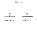
- FIG. 3 is a block diagram illustrating an apparatus for preventing a rollback of a construction machine in accordance with example embodiments.
- an apparatus for preventing a rollback of a construction machine in accordance with example embodiments may include a wheel sensor 310 and a controller 320.
- the wheel sensor 310 may be attached to the wheel of the wheel excavator.
- the wheel sensor 310 may detect rotating directions of the wheel. Particularly, the wheel sensor 310 may detect the rotating direction of the wheel that may be a forward direction or a backward direction. Thus, the wheel sensor 310 may detect an actual driving direction of the wheel excavator.
- the controller 320 may receive data obtained from the wheel sensor 310, i.e., the actual driving direction of the wheel excavator.
- the controller 320 may compare a detected driving direction of the wheel excavator with a desired driving direction of the wheel excavator of a driver.
- the controller 320 may determine whether the detected driving direction may be coincided with the desired direction or not.
- the controller 320 may maximumly set an oil discharge amount of the driving motor.
- the maximum oil discharge amount may function as to increase a torque required for rotating the driving motor. Therefore, a hydraulic brake force may be naturally generated from the driving motor. As a result, the hydraulic brake force may be applied to the backwardly moved wheel excavator to prevent the rollback of the wheel excavator in the slope.
- FIG. 4 is a flow chart illustrating a method of preventing the rollback of the construction machine using the apparatus in FIG. 3 .
- the driver may upwardly move the wheel excavator on the slope by the forward drive or the backward drive.
- the wheel sensor 310 may detect an actual driving direction of the wheel excavator.
- the wheel sensor 310 may detect the power transmission direction of the transmission that may correspond to the upward direction or the downward direction of the wheel excavator.
- step ST420 the actual driving direction of the wheel excavator detected by the wheel sensor 310 may be transmitted to the controller 320.
- step ST430 the controller 320 may compare the actual driving direction with the desired driving direction to determine whether the actual driving direction may be coincided with the desired driving direction or not.
- step ST440 when the driver may intend to upwardly move the wheel excavator and the actual driving direction detected by the wheel sensor 310 may be the upward direction, the controller 320 may still maintain the normal drive of the wheel excavator.
- step ST450 when the driver may intend to upwardly move the wheel excavator and the actual driving direction detected by the wheel sensor 310 may be the downward direction caused by the weight of the wheel excavator, the controller 320 may control a swash plate angle of the driving motor to maximumly set the oil discharge amount of the driving motor.
- the oil discharge amount may be maximal, the torque required for rotating the driving motor may be increased to generate the hydraulic brake force from the driving motor. Therefore, the hydraulic brake force may be applied to the backwardly moved wheel excavator on the slope to prevent the rollback of the wheel excavator on the slope.
- step ST460 during applying the hydraulic brake force to the wheel excavator, the controller 320 may continuously determine whether the actual driving direction may be coincided with the desired driving direction or not.
- step ST440 the controller 320 may convert the wheel excavator into the normal drive.
- step ST450 the controller 320 may control the driving motor to generate the hydraulic brake force to prevent the rollback of the wheel excavator in the slope.
- the hydraulic brake force may be generated from the driving motor.
- the hydraulic brake force may be applied to the construction machine to prevent the rollback of the construction machine.
Landscapes
- Engineering & Computer Science (AREA)
- Mechanical Engineering (AREA)
- Transportation (AREA)
- General Engineering & Computer Science (AREA)
- Structural Engineering (AREA)
- Civil Engineering (AREA)
- Mining & Mineral Resources (AREA)
- Chemical & Material Sciences (AREA)
- Combustion & Propulsion (AREA)
- Physics & Mathematics (AREA)
- Automation & Control Theory (AREA)
- Mathematical Physics (AREA)
- Operation Control Of Excavators (AREA)
Abstract
Description
- Example embodiments relate to a method of preventing a rollback of a construction machine and an apparatus for performing the same. More particularly, example embodiments relate to a method of preventing a rollback of a wheel excavator, and an apparatus for performing the method.
- Generally, an excavator may include a lower driving body, an upper swing body pivotally connected to the lower driving body, a boom connected to the upper swing body, an arm connected to the boom, and an attachment selectively connected to the arm. The attachment may include a bucket, breaker, crusher, etc.
- According to related arts, when the excavator stopped on a slope may be upwardly moved, the excavator may be backwardly moved due to a weight of the excavator to generate a safety accident. Particularly, when the excavator may be backwardly moved severely, a rollover of the excavator may be generated.
- Example embodiments provide a method of preventing a rollback of a construction machine on a slope.
- Example embodiments also provide an apparatus for performing the above-mentioned method.
- According to example embodiments, there may be provided a method of preventing a rollback of a construction machine. In the method of preventing the rollback of the construction machine, a driving direction of the construction machine on a slope may be detected. A detected driving direction of the construction machine may be compared with a desired driving direction of a driver for the construction machine. A hydraulic brake force may be selectively generated using a driving motor in the construction machine in accordance with comparison results.
- In example embodiments, detecting the driving direction of the construction machine may include detecting an operating direction of a transmission in the construction machine.
- In example embodiments, detecting the driving direction of the construction machine may include detecting a rotating direction of a wheel in the construction machine.
- In example embodiments, generating the hydraulic brake force may include maximumly setting an oil discharge amount of the driving motor.
- In example embodiments, the construction machine may include a wheel excavator.
- According to example embodiments, there may be provided an apparatus for preventing a rollback of a construction machine. The apparatus may include a sensor and a controller. The sensor may detect a driving direction of the construction machine on a slope. The controller may compare a detected driving direction of the construction machine with a desired driving direction of a driver for the construction machine. The controller may selectively generate a hydraulic brake force using a driving motor in the construction machine in accordance with comparison results.
- In example embodiments, the sensor may include a transmission sensor configured to sense an operating direction of a transmission in the construction machine.
- In example embodiments, the sensor may include a wheel sensor configured to sense a rotating direction of a wheel in the construction machine.
- In example embodiments, the controller may maximumly set an oil discharge amount of the driving motor.
- In example embodiments, the construction machine may include a wheel excavator.
- According to example embodiments, when the desired driving direction of the driver may not be coincided with the actual driving direction of the construction machine, the hydraulic brake force may be generated from the driving motor. Thus, the hydraulic brake force may be applied to the construction machine to prevent the rollback of the construction machine.
- Example embodiments will be more clearly understood from the following detailed description taken in conjunction with the accompanying drawings.
FIGS. 1 to 4 represent non-limiting, example embodiments as described herein. -
FIG. 1 is a block diagram illustrating an apparatus for preventing a rollback of a construction machine in accordance with example embodiments; -
FIG. 2 is a flow chart illustrating a method of preventing the rollback of the construction machine using the apparatus inFIG. 1 ; -
FIG. 3 is a block diagram illustrating an apparatus for preventing a rollback of a construction machine in accordance with example embodiments; and -
FIG. 4 is a flow chart illustrating a method of preventing the rollback of the construction machine using the apparatus inFIG. 3 . - Various example embodiments will be described more fully hereinafter with reference to the accompanying drawings, in which some example embodiments are shown. The present invention may, however, be embodied in many different forms and should not be construed as limited to the example embodiments set forth herein. Rather, these example embodiments are provided so that this disclosure will be thorough and complete, and will fully convey the scope of the present invention to those skilled in the art. In the drawings, the sizes and relative sizes of layers and regions may be exaggerated for clarity.
- It will be understood that when an element or layer is referred to as being "on," "connected to" or "coupled to" another element or layer, it can be directly on, connected or coupled to the other element or layer or intervening elements or layers may be present. In contrast, when an element is referred to as being "directly on," "directly connected to" or "directly coupled to" another element or layer, there are no intervening elements or layers present. Like numerals refer to like elements throughout. As used herein, the term "and/or" includes any and all combinations of one or more of the associated listed items.
- It will be understood that, although the terms first, second, third etc. may be used herein to describe various elements, components, regions, layers and/or sections, these elements, components, regions, layers and/or sections should not be limited by these terms. These terms are only used to distinguish one element, component, region, layer or section from another region, layer or section. Thus, a first element, component, region, layer or section discussed below could be termed a second element, component, region, layer or section without departing from the teachings of the present invention.
- Spatially relative terms, such as "beneath," "below," "lower," "above," "upper" and the like, may be used herein for ease of description to describe one element or feature's relationship to another element(s) or feature(s) as illustrated in the figures. It will be understood that the spatially relative terms are intended to encompass different orientations of the device in use or operation in addition to the orientation depicted in the figures. For example, if the device in the figures is turned over, elements described as "below" or "beneath" other elements or features would then be oriented "above" the other elements or features. Thus, the exemplary term "below" can encompass both an orientation of above and below. The device may be otherwise oriented (rotated 90 degrees or at other orientations) and the spatially relative descriptors used herein interpreted accordingly.
- The terminology used herein is for the purpose of describing particular example embodiments only and is not intended to be limiting of the present invention. As used herein, the singular forms "a," "an" and "the" are intended to include the plural forms as well, unless the context clearly indicates otherwise. It will be further understood that the terms "comprises" and/or "comprising," when used in this specification, specify the presence of stated features, integers, steps, operations, elements, and/or components, but do not preclude the presence or addition of one or more other features, integers, steps, operations, elements, components, and/or groups thereof.
- Example embodiments are described herein with reference to cross-sectional illustrations that are schematic illustrations of idealized example embodiments (and intermediate structures). As such, variations from the shapes of the illustrations as a result, for example, of manufacturing techniques and/or tolerances, are to be expected. Thus, example embodiments should not be construed as limited to the particular shapes of regions illustrated herein but are to include deviations in shapes that result, for example, from manufacturing. For example, an implanted region illustrated as a rectangle will, typically, have rounded or curved features and/or a gradient of implant concentration at its edges rather than a binary change from implanted to non-implanted region. Likewise, a buried region formed by implantation may result in some implantation in the region between the buried region and the surface through which the implantation takes place. Thus, the regions illustrated in the figures are schematic in nature and their shapes are not intended to illustrate the actual shape of a region of a device and are not intended to limit the scope of the present invention.
- Unless otherwise defined, all terms (including technical and scientific terms) used herein have the same meaning as commonly understood by one of ordinary skill in the art to which this invention belongs. It will be further understood that terms, such as those defined in commonly used dictionaries, should be interpreted as having a meaning that is consistent with their meaning in the context of the relevant art and will not be interpreted in an idealized or overly formal sense unless expressly so defined herein.
- Hereinafter, example embodiments will be explained in detail with reference to the accompanying drawings.
-
FIG. 1 is a block diagram illustrating an apparatus for preventing a rollback of a construction machine in accordance with example embodiments. - Referring to
FIG. 1 , an apparatus for preventing a rollback of a construction machine in accordance with example embodiments may include atransmission sensor 110 and acontroller 120. - In example embodiments, the construction machine may include a wheel excavator. The wheel excavator may be moved by wheels rotated using a hydraulic pressure that may be generated from a driving motor. Thus, the wheel excavator may be moved forwardly or backwardly in accordance with transmitting directions of the hydraulic pressure in the transmission and rotating directions of the wheels. Alternatively, the construction machine may include a wheel loader besides the wheel excavator.
- The
transmission sensor 110 may be attached to the transmission of the wheel excavator. Thetransmission sensor 110 may detect operating directions of the transmission. Particularly, thetransmission sensor 110 may detect whether a power transmission direction of the transmission may be a forward direction or a backward direction. Thus, thetransmission sensor 110 may detect an actual driving direction of the wheel excavator. - The
controller 120 may receive data obtained from thetransmission sensor 110, i.e., the actual driving direction of the wheel excavator. Thecontroller 120 may compare a detected driving direction of the wheel excavator with a desired driving direction of the wheel excavator of a driver. Thecontroller 120 may determine whether the detected driving direction may be coincided with the desired direction or not. In example embodiments, thecontroller 120 may include a transmission control unit (TCU). - For example, upward movements of the wheel excavator stopped on a slope may be classified into a forward drive and a backward drive. When a cabin of the wheel excavator may be upwardly oriented on the slope, the driver may upwardly move the wheel excavator by the forward drive. In contrast, when the cabin may be downwardly oriented on the slope, the driver may upwardly move the wheel excavator by the backward drive. In the forward drive and the backward drive, the wheel excavator may be downwardly moved by a weight of the wheel excavator.
- When the actual driving direction of the wheel excavator may be the downward direction due to the weight of the wheel excavator, although the desired driving direction of the driver may be the upward direction, the
controller 120 may maximumly set an oil discharge amount of the driving motor. The maximum oil discharge amount may function as to increase a torque required for rotating the driving motor. Therefore, a hydraulic brake force may be naturally generated from the driving motor. As a result, the hydraulic brake force may be applied to the backwardly moved wheel excavator to prevent the rollback of the wheel excavator in the slope. -
FIG. 2 is a flow chart illustrating a method of preventing the rollback of the construction machine using the apparatus inFIG. 1 . - Referring to
FIGS. 1 and2 , the driver may upwardly move the wheel excavator on the slope by the forward drive or the backward drive. In step ST210, thetransmission sensor 110 may detect an actual driving direction of the wheel excavator. Particularly, thetransmission sensor 110 may detect the power transmission direction of the transmission that may correspond to the upward direction or the downward direction of the wheel excavator. - In step ST220, the actual driving direction of the wheel excavator detected by the
transmission sensor 110 may be transmitted to thecontroller 120. - In step ST230, the
controller 120 may compare the actual driving direction with the desired driving direction to determine whether the actual driving direction may be coincided with the desired driving direction or not. - In step ST240, when the driver may intend to upwardly move the wheel excavator and the actual driving direction detected by the
transmission sensor 110 may be the upward direction, thecontroller 120 may still maintain the normal drive of the wheel excavator. - In contrast, in step ST250, when the driver may intend to upwardly move the wheel excavator and the actual driving direction detected by the
transmission sensor 110 may be the downward direction caused by the weight of the wheel excavator, thecontroller 120 may control a swash plate angle of the driving motor to maximumly set the oil discharge amount of the driving motor. When the oil discharge amount may be maximal, the torque required for rotating the driving motor may be increased to generate the hydraulic brake force from the driving motor. Therefore, the hydraulic brake force may be applied to the backwardly moved wheel excavator on the slope to prevent the rollback of the wheel excavator on the slope. - In step ST260, during applying the hydraulic brake force to the wheel excavator, the
controller 120 may continuously determine whether the actual driving direction may be coincided with the desired driving direction or not. - When the actual driving direction may be coincided with the desired driving direction, in step ST240, the
controller 120 may convert the wheel excavator into the normal drive. - In contrast, when the actual driving direction may not be coincided with the desired driving direction, in step ST250, the
controller 120 may control the driving motor to generate the hydraulic brake force to prevent the rollback of the wheel excavator in the slope. -
FIG. 3 is a block diagram illustrating an apparatus for preventing a rollback of a construction machine in accordance with example embodiments. - Referring to
FIG. 3 , an apparatus for preventing a rollback of a construction machine in accordance with example embodiments may include awheel sensor 310 and acontroller 320. - The
wheel sensor 310 may be attached to the wheel of the wheel excavator. Thewheel sensor 310 may detect rotating directions of the wheel. Particularly, thewheel sensor 310 may detect the rotating direction of the wheel that may be a forward direction or a backward direction. Thus, thewheel sensor 310 may detect an actual driving direction of the wheel excavator. - The
controller 320 may receive data obtained from thewheel sensor 310, i.e., the actual driving direction of the wheel excavator. Thecontroller 320 may compare a detected driving direction of the wheel excavator with a desired driving direction of the wheel excavator of a driver. Thecontroller 320 may determine whether the detected driving direction may be coincided with the desired direction or not. - When the actual driving direction of the wheel excavator may be the downward direction due to the weight of the wheel excavator, although the desired driving direction of the driver may be the upward direction, the
controller 320 may maximumly set an oil discharge amount of the driving motor. The maximum oil discharge amount may function as to increase a torque required for rotating the driving motor. Therefore, a hydraulic brake force may be naturally generated from the driving motor. As a result, the hydraulic brake force may be applied to the backwardly moved wheel excavator to prevent the rollback of the wheel excavator in the slope. -
FIG. 4 is a flow chart illustrating a method of preventing the rollback of the construction machine using the apparatus inFIG. 3 . - Referring to
FIGS. 3 and4 , the driver may upwardly move the wheel excavator on the slope by the forward drive or the backward drive. In step ST410, thewheel sensor 310 may detect an actual driving direction of the wheel excavator. Particularly, thewheel sensor 310 may detect the power transmission direction of the transmission that may correspond to the upward direction or the downward direction of the wheel excavator. - In step ST420, the actual driving direction of the wheel excavator detected by the
wheel sensor 310 may be transmitted to thecontroller 320. - In step ST430, the
controller 320 may compare the actual driving direction with the desired driving direction to determine whether the actual driving direction may be coincided with the desired driving direction or not. - In step ST440, when the driver may intend to upwardly move the wheel excavator and the actual driving direction detected by the
wheel sensor 310 may be the upward direction, thecontroller 320 may still maintain the normal drive of the wheel excavator. - In contrast, in step ST450, when the driver may intend to upwardly move the wheel excavator and the actual driving direction detected by the
wheel sensor 310 may be the downward direction caused by the weight of the wheel excavator, thecontroller 320 may control a swash plate angle of the driving motor to maximumly set the oil discharge amount of the driving motor. When the oil discharge amount may be maximal, the torque required for rotating the driving motor may be increased to generate the hydraulic brake force from the driving motor. Therefore, the hydraulic brake force may be applied to the backwardly moved wheel excavator on the slope to prevent the rollback of the wheel excavator on the slope. - In step ST460, during applying the hydraulic brake force to the wheel excavator, the
controller 320 may continuously determine whether the actual driving direction may be coincided with the desired driving direction or not. - When the actual driving direction may be coincided with the desired driving direction, in step ST440, the
controller 320 may convert the wheel excavator into the normal drive. - In contrast, when the actual driving direction may not be coincided with the desired driving direction, in step ST450, the
controller 320 may control the driving motor to generate the hydraulic brake force to prevent the rollback of the wheel excavator in the slope. - According to example embodiments, when the desired driving direction of the driver may not be coincided with the actual driving direction of the construction machine, the hydraulic brake force may be generated from the driving motor. Thus, the hydraulic brake force may be applied to the construction machine to prevent the rollback of the construction machine.
Claims (10)
- A method of preventing a rollback of a construction machine, the method comprising:detecting a driving direction of the construction machine on a slope;comparing the driving direction of the construction machine with a desired driving direction of a driver for the construction machine; andselectively generating a hydraulic brake force using a driving motor of the construction machine in accordance with comparison results.
- The method of claim 1, wherein detecting the driving direction of the construction machine comprises detecting an operating direction of a transmission in the construction machine.
- The method of claim 1, wherein detecting the driving direction of the construction machine comprises detecting a rotating direction of a wheel in the construction machine.
- The method of claim 1, wherein generating the hydraulic brake force comprises maximumly setting an oil discharge amount of the driving motor.
- The method of claim 1, wherein the construction machine comprises a wheel excavator.
- An apparatus for preventing a rollback of a construction machine, the apparatus comprising:a sensor configured to detect a driving direction of the construction machine on a slope; anda controller configured to compare the driving direction of the construction machine with a desired driving direction of a driver for the construction machine, and to selectively generate a hydraulic brake force using a driving motor of the construction machine in accordance with comparison results.
- The apparatus of claim 6, wherein the sensor comprises a transmission sensor configured to detect an operating direction of a transmission in the construction machine.
- The apparatus of claim 6, wherein the sensor comprises a wheel sensor configured to detect a rotating direction of a wheel in the construction machine.
- The apparatus of claim 6, wherein the controller is configured to maximumly sett an oil discharge amount of the driving motor for generating the hydraulic brake force.
- The apparatus of claim 6, wherein the construction machine comprises a wheel excavator.
Applications Claiming Priority (1)
| Application Number | Priority Date | Filing Date | Title |
|---|---|---|---|
| KR1020140187917A KR102272247B1 (en) | 2014-12-24 | 2014-12-24 | Method of preventing a rollback of a construction machine and apparatus for performing the same |
Publications (2)
| Publication Number | Publication Date |
|---|---|
| EP3037590A1 true EP3037590A1 (en) | 2016-06-29 |
| EP3037590B1 EP3037590B1 (en) | 2022-03-30 |
Family
ID=54783491
Family Applications (1)
| Application Number | Title | Priority Date | Filing Date |
|---|---|---|---|
| EP15198147.9A Active EP3037590B1 (en) | 2014-12-24 | 2015-12-07 | Method of preventing a rollback of a construction machine and apparatus for performing the same |
Country Status (2)
| Country | Link |
|---|---|
| EP (1) | EP3037590B1 (en) |
| KR (1) | KR102272247B1 (en) |
Cited By (1)
| Publication number | Priority date | Publication date | Assignee | Title |
|---|---|---|---|---|
| WO2020065915A1 (en) * | 2018-09-28 | 2020-04-02 | 日立建機株式会社 | Wheel loader |
Families Citing this family (1)
| Publication number | Priority date | Publication date | Assignee | Title |
|---|---|---|---|---|
| KR102450762B1 (en) * | 2021-02-18 | 2022-10-07 | 주식회사 현대케피코 | System for controlling stop of vehicle and method thereof |
Citations (2)
| Publication number | Priority date | Publication date | Assignee | Title |
|---|---|---|---|---|
| WO2013122101A1 (en) * | 2012-02-17 | 2013-08-22 | 日立建機株式会社 | Electrically driven working vehicle |
| US20130261909A1 (en) * | 2012-03-27 | 2013-10-03 | SriVidya Lavanya Kamisetty | Rollback prevention system for mobile machine |
-
2014
- 2014-12-24 KR KR1020140187917A patent/KR102272247B1/en active IP Right Grant
-
2015
- 2015-12-07 EP EP15198147.9A patent/EP3037590B1/en active Active
Patent Citations (2)
| Publication number | Priority date | Publication date | Assignee | Title |
|---|---|---|---|---|
| WO2013122101A1 (en) * | 2012-02-17 | 2013-08-22 | 日立建機株式会社 | Electrically driven working vehicle |
| US20130261909A1 (en) * | 2012-03-27 | 2013-10-03 | SriVidya Lavanya Kamisetty | Rollback prevention system for mobile machine |
Cited By (1)
| Publication number | Priority date | Publication date | Assignee | Title |
|---|---|---|---|---|
| WO2020065915A1 (en) * | 2018-09-28 | 2020-04-02 | 日立建機株式会社 | Wheel loader |
Also Published As
| Publication number | Publication date |
|---|---|
| KR20160077699A (en) | 2016-07-04 |
| EP3037590B1 (en) | 2022-03-30 |
| KR102272247B1 (en) | 2021-07-02 |
Similar Documents
| Publication | Publication Date | Title |
|---|---|---|
| US11697916B2 (en) | Excavator and method of controlling the same | |
| US11761172B2 (en) | Automated control of dipper swing for a shovel | |
| KR101372781B1 (en) | Shovel | |
| US8639429B2 (en) | Wheel loader and method for controlling a wheel loader | |
| US10011273B2 (en) | Work vehicle and method for controlling same | |
| US8649945B2 (en) | Wheel loader and wheel loader control method | |
| US11655611B2 (en) | Shovel | |
| US20140144129A1 (en) | Work vehicle and work vehicle control method | |
| US9506221B2 (en) | System and method of vector drive control for a mining machine | |
| US9598837B2 (en) | Excavation system providing automated stall correction | |
| RU2684818C2 (en) | Method for automatic orientation of materials handling vehicle to any desired angle (versions) | |
| EP3037590A1 (en) | Method of preventing a rollback of a construction machine and apparatus for performing the same | |
| CN108779622B (en) | Working vehicle | |
| EP3342936A1 (en) | Wheel loader | |
| EP2657492B1 (en) | Low idle control system of construction equipment and automatic control method thereof | |
| US11946219B2 (en) | Work machine, control device, and control method | |
| JPWO2017138070A1 (en) | Work vehicle and operation control method | |
| JP2011179180A (en) | Construction vehicle having work machine | |
| CN106869203B (en) | Rotation control device for hybrid construction machine and hybrid construction machine | |
| US20240229414A9 (en) | Work machine and method for controlling work machine | |
| JP2022184018A (en) | Work machine and method of controlling the same | |
| KR20160144707A (en) | Control system for construction machinery | |
| KR101986378B1 (en) | Hydraulic system of construction machinery |
Legal Events
| Date | Code | Title | Description |
|---|---|---|---|
| PUAI | Public reference made under article 153(3) epc to a published international application that has entered the european phase |
Free format text: ORIGINAL CODE: 0009012 |
|
| 17P | Request for examination filed |
Effective date: 20151207 |
|
| AK | Designated contracting states |
Kind code of ref document: A1 Designated state(s): AL AT BE BG CH CY CZ DE DK EE ES FI FR GB GR HR HU IE IS IT LI LT LU LV MC MK MT NL NO PL PT RO RS SE SI SK SM TR |
|
| AX | Request for extension of the european patent |
Extension state: BA ME |
|
| STAA | Information on the status of an ep patent application or granted ep patent |
Free format text: STATUS: REQUEST FOR EXAMINATION WAS MADE |
|
| R17P | Request for examination filed (corrected) |
Effective date: 20151207 |
|
| RBV | Designated contracting states (corrected) |
Designated state(s): AL AT BE BG CH CY CZ DE DK EE ES FI FR GB GR HR HU IE IS IT LI LT LU LV MC MK MT NL NO PL PT RO RS SE SI SK SM TR |
|
| STAA | Information on the status of an ep patent application or granted ep patent |
Free format text: STATUS: EXAMINATION IS IN PROGRESS |
|
| 17Q | First examination report despatched |
Effective date: 20210330 |
|
| GRAP | Despatch of communication of intention to grant a patent |
Free format text: ORIGINAL CODE: EPIDOSNIGR1 |
|
| STAA | Information on the status of an ep patent application or granted ep patent |
Free format text: STATUS: GRANT OF PATENT IS INTENDED |
|
| RAP3 | Party data changed (applicant data changed or rights of an application transferred) |
Owner name: HYUNDAI DOOSAN INFRACORE CO., LTD. |
|
| INTG | Intention to grant announced |
Effective date: 20211123 |
|
| GRAS | Grant fee paid |
Free format text: ORIGINAL CODE: EPIDOSNIGR3 |
|
| GRAA | (expected) grant |
Free format text: ORIGINAL CODE: 0009210 |
|
| STAA | Information on the status of an ep patent application or granted ep patent |
Free format text: STATUS: THE PATENT HAS BEEN GRANTED |
|
| AK | Designated contracting states |
Kind code of ref document: B1 Designated state(s): AL AT BE BG CH CY CZ DE DK EE ES FI FR GB GR HR HU IE IS IT LI LT LU LV MC MK MT NL NO PL PT RO RS SE SI SK SM TR |
|
| REG | Reference to a national code |
Ref country code: GB Ref legal event code: FG4D |
|
| REG | Reference to a national code |
Ref country code: CH Ref legal event code: EP |
|
| REG | Reference to a national code |
Ref country code: AT Ref legal event code: REF Ref document number: 1479302 Country of ref document: AT Kind code of ref document: T Effective date: 20220415 |
|
| REG | Reference to a national code |
Ref country code: DE Ref legal event code: R096 Ref document number: 602015077825 Country of ref document: DE |
|
| REG | Reference to a national code |
Ref country code: IE Ref legal event code: FG4D |
|
| REG | Reference to a national code |
Ref country code: LT Ref legal event code: MG9D |
|
| PG25 | Lapsed in a contracting state [announced via postgrant information from national office to epo] |
Ref country code: SE Free format text: LAPSE BECAUSE OF FAILURE TO SUBMIT A TRANSLATION OF THE DESCRIPTION OR TO PAY THE FEE WITHIN THE PRESCRIBED TIME-LIMIT Effective date: 20220330 Ref country code: RS Free format text: LAPSE BECAUSE OF FAILURE TO SUBMIT A TRANSLATION OF THE DESCRIPTION OR TO PAY THE FEE WITHIN THE PRESCRIBED TIME-LIMIT Effective date: 20220330 Ref country code: NO Free format text: LAPSE BECAUSE OF FAILURE TO SUBMIT A TRANSLATION OF THE DESCRIPTION OR TO PAY THE FEE WITHIN THE PRESCRIBED TIME-LIMIT Effective date: 20220630 Ref country code: LT Free format text: LAPSE BECAUSE OF FAILURE TO SUBMIT A TRANSLATION OF THE DESCRIPTION OR TO PAY THE FEE WITHIN THE PRESCRIBED TIME-LIMIT Effective date: 20220330 Ref country code: HR Free format text: LAPSE BECAUSE OF FAILURE TO SUBMIT A TRANSLATION OF THE DESCRIPTION OR TO PAY THE FEE WITHIN THE PRESCRIBED TIME-LIMIT Effective date: 20220330 Ref country code: BG Free format text: LAPSE BECAUSE OF FAILURE TO SUBMIT A TRANSLATION OF THE DESCRIPTION OR TO PAY THE FEE WITHIN THE PRESCRIBED TIME-LIMIT Effective date: 20220630 |
|
| REG | Reference to a national code |
Ref country code: NL Ref legal event code: MP Effective date: 20220330 |
|
| REG | Reference to a national code |
Ref country code: AT Ref legal event code: MK05 Ref document number: 1479302 Country of ref document: AT Kind code of ref document: T Effective date: 20220330 |
|
| PG25 | Lapsed in a contracting state [announced via postgrant information from national office to epo] |
Ref country code: LV Free format text: LAPSE BECAUSE OF FAILURE TO SUBMIT A TRANSLATION OF THE DESCRIPTION OR TO PAY THE FEE WITHIN THE PRESCRIBED TIME-LIMIT Effective date: 20220330 Ref country code: GR Free format text: LAPSE BECAUSE OF FAILURE TO SUBMIT A TRANSLATION OF THE DESCRIPTION OR TO PAY THE FEE WITHIN THE PRESCRIBED TIME-LIMIT Effective date: 20220701 Ref country code: FI Free format text: LAPSE BECAUSE OF FAILURE TO SUBMIT A TRANSLATION OF THE DESCRIPTION OR TO PAY THE FEE WITHIN THE PRESCRIBED TIME-LIMIT Effective date: 20220330 |
|
| PG25 | Lapsed in a contracting state [announced via postgrant information from national office to epo] |
Ref country code: NL Free format text: LAPSE BECAUSE OF FAILURE TO SUBMIT A TRANSLATION OF THE DESCRIPTION OR TO PAY THE FEE WITHIN THE PRESCRIBED TIME-LIMIT Effective date: 20220330 |
|
| PG25 | Lapsed in a contracting state [announced via postgrant information from national office to epo] |
Ref country code: SM Free format text: LAPSE BECAUSE OF FAILURE TO SUBMIT A TRANSLATION OF THE DESCRIPTION OR TO PAY THE FEE WITHIN THE PRESCRIBED TIME-LIMIT Effective date: 20220330 Ref country code: SK Free format text: LAPSE BECAUSE OF FAILURE TO SUBMIT A TRANSLATION OF THE DESCRIPTION OR TO PAY THE FEE WITHIN THE PRESCRIBED TIME-LIMIT Effective date: 20220330 Ref country code: RO Free format text: LAPSE BECAUSE OF FAILURE TO SUBMIT A TRANSLATION OF THE DESCRIPTION OR TO PAY THE FEE WITHIN THE PRESCRIBED TIME-LIMIT Effective date: 20220330 Ref country code: PT Free format text: LAPSE BECAUSE OF FAILURE TO SUBMIT A TRANSLATION OF THE DESCRIPTION OR TO PAY THE FEE WITHIN THE PRESCRIBED TIME-LIMIT Effective date: 20220801 Ref country code: ES Free format text: LAPSE BECAUSE OF FAILURE TO SUBMIT A TRANSLATION OF THE DESCRIPTION OR TO PAY THE FEE WITHIN THE PRESCRIBED TIME-LIMIT Effective date: 20220330 Ref country code: EE Free format text: LAPSE BECAUSE OF FAILURE TO SUBMIT A TRANSLATION OF THE DESCRIPTION OR TO PAY THE FEE WITHIN THE PRESCRIBED TIME-LIMIT Effective date: 20220330 Ref country code: CZ Free format text: LAPSE BECAUSE OF FAILURE TO SUBMIT A TRANSLATION OF THE DESCRIPTION OR TO PAY THE FEE WITHIN THE PRESCRIBED TIME-LIMIT Effective date: 20220330 Ref country code: AT Free format text: LAPSE BECAUSE OF FAILURE TO SUBMIT A TRANSLATION OF THE DESCRIPTION OR TO PAY THE FEE WITHIN THE PRESCRIBED TIME-LIMIT Effective date: 20220330 |
|
| PG25 | Lapsed in a contracting state [announced via postgrant information from national office to epo] |
Ref country code: PL Free format text: LAPSE BECAUSE OF FAILURE TO SUBMIT A TRANSLATION OF THE DESCRIPTION OR TO PAY THE FEE WITHIN THE PRESCRIBED TIME-LIMIT Effective date: 20220330 Ref country code: IS Free format text: LAPSE BECAUSE OF FAILURE TO SUBMIT A TRANSLATION OF THE DESCRIPTION OR TO PAY THE FEE WITHIN THE PRESCRIBED TIME-LIMIT Effective date: 20220730 Ref country code: AL Free format text: LAPSE BECAUSE OF FAILURE TO SUBMIT A TRANSLATION OF THE DESCRIPTION OR TO PAY THE FEE WITHIN THE PRESCRIBED TIME-LIMIT Effective date: 20220330 |
|
| REG | Reference to a national code |
Ref country code: DE Ref legal event code: R097 Ref document number: 602015077825 Country of ref document: DE |
|
| PG25 | Lapsed in a contracting state [announced via postgrant information from national office to epo] |
Ref country code: DK Free format text: LAPSE BECAUSE OF FAILURE TO SUBMIT A TRANSLATION OF THE DESCRIPTION OR TO PAY THE FEE WITHIN THE PRESCRIBED TIME-LIMIT Effective date: 20220330 |
|
| PLBE | No opposition filed within time limit |
Free format text: ORIGINAL CODE: 0009261 |
|
| STAA | Information on the status of an ep patent application or granted ep patent |
Free format text: STATUS: NO OPPOSITION FILED WITHIN TIME LIMIT |
|
| 26N | No opposition filed |
Effective date: 20230103 |
|
| PG25 | Lapsed in a contracting state [announced via postgrant information from national office to epo] |
Ref country code: SI Free format text: LAPSE BECAUSE OF FAILURE TO SUBMIT A TRANSLATION OF THE DESCRIPTION OR TO PAY THE FEE WITHIN THE PRESCRIBED TIME-LIMIT Effective date: 20220330 |
|
| PG25 | Lapsed in a contracting state [announced via postgrant information from national office to epo] |
Ref country code: IT Free format text: LAPSE BECAUSE OF FAILURE TO SUBMIT A TRANSLATION OF THE DESCRIPTION OR TO PAY THE FEE WITHIN THE PRESCRIBED TIME-LIMIT Effective date: 20220330 |
|
| REG | Reference to a national code |
Ref country code: CH Ref legal event code: PL |
|
| GBPC | Gb: european patent ceased through non-payment of renewal fee |
Effective date: 20221207 |
|
| REG | Reference to a national code |
Ref country code: BE Ref legal event code: MM Effective date: 20221231 |
|
| PG25 | Lapsed in a contracting state [announced via postgrant information from national office to epo] |
Ref country code: LU Free format text: LAPSE BECAUSE OF NON-PAYMENT OF DUE FEES Effective date: 20221207 |
|
| PG25 | Lapsed in a contracting state [announced via postgrant information from national office to epo] |
Ref country code: LI Free format text: LAPSE BECAUSE OF NON-PAYMENT OF DUE FEES Effective date: 20221231 Ref country code: IE Free format text: LAPSE BECAUSE OF NON-PAYMENT OF DUE FEES Effective date: 20221207 Ref country code: GB Free format text: LAPSE BECAUSE OF NON-PAYMENT OF DUE FEES Effective date: 20221207 Ref country code: CH Free format text: LAPSE BECAUSE OF NON-PAYMENT OF DUE FEES Effective date: 20221231 |
|
| PG25 | Lapsed in a contracting state [announced via postgrant information from national office to epo] |
Ref country code: FR Free format text: LAPSE BECAUSE OF NON-PAYMENT OF DUE FEES Effective date: 20221231 Ref country code: BE Free format text: LAPSE BECAUSE OF NON-PAYMENT OF DUE FEES Effective date: 20221231 |
|
| REG | Reference to a national code |
Ref country code: DE Ref legal event code: R081 Ref document number: 602015077825 Country of ref document: DE Owner name: HD HYUNDAI INFRACORE CO., LTD., KR Free format text: FORMER OWNER: HYUNDAI DOOSAN INFRACORE CO., LTD., INCHEON, KR |
|
| PGFP | Annual fee paid to national office [announced via postgrant information from national office to epo] |
Ref country code: DE Payment date: 20231024 Year of fee payment: 9 |
|
| PG25 | Lapsed in a contracting state [announced via postgrant information from national office to epo] |
Ref country code: HU Free format text: LAPSE BECAUSE OF FAILURE TO SUBMIT A TRANSLATION OF THE DESCRIPTION OR TO PAY THE FEE WITHIN THE PRESCRIBED TIME-LIMIT; INVALID AB INITIO Effective date: 20151207 |
|
| PG25 | Lapsed in a contracting state [announced via postgrant information from national office to epo] |
Ref country code: CY Free format text: LAPSE BECAUSE OF FAILURE TO SUBMIT A TRANSLATION OF THE DESCRIPTION OR TO PAY THE FEE WITHIN THE PRESCRIBED TIME-LIMIT Effective date: 20220330 |
|
| PG25 | Lapsed in a contracting state [announced via postgrant information from national office to epo] |
Ref country code: MK Free format text: LAPSE BECAUSE OF FAILURE TO SUBMIT A TRANSLATION OF THE DESCRIPTION OR TO PAY THE FEE WITHIN THE PRESCRIBED TIME-LIMIT Effective date: 20220330 |
|
| PG25 | Lapsed in a contracting state [announced via postgrant information from national office to epo] |
Ref country code: MC Free format text: LAPSE BECAUSE OF FAILURE TO SUBMIT A TRANSLATION OF THE DESCRIPTION OR TO PAY THE FEE WITHIN THE PRESCRIBED TIME-LIMIT Effective date: 20220330 |
|
| PG25 | Lapsed in a contracting state [announced via postgrant information from national office to epo] |
Ref country code: TR Free format text: LAPSE BECAUSE OF FAILURE TO SUBMIT A TRANSLATION OF THE DESCRIPTION OR TO PAY THE FEE WITHIN THE PRESCRIBED TIME-LIMIT Effective date: 20220330 Ref country code: MC Free format text: LAPSE BECAUSE OF FAILURE TO SUBMIT A TRANSLATION OF THE DESCRIPTION OR TO PAY THE FEE WITHIN THE PRESCRIBED TIME-LIMIT Effective date: 20220330 |