EP3037238A1 - Mesh filter - Google Patents
Mesh filter Download PDFInfo
- Publication number
- EP3037238A1 EP3037238A1 EP14838343.3A EP14838343A EP3037238A1 EP 3037238 A1 EP3037238 A1 EP 3037238A1 EP 14838343 A EP14838343 A EP 14838343A EP 3037238 A1 EP3037238 A1 EP 3037238A1
- Authority
- EP
- European Patent Office
- Prior art keywords
- inner cylinder
- filter unit
- axis
- mesh filter
- mold
- Prior art date
- Legal status (The legal status is an assumption and is not a legal conclusion. Google has not performed a legal analysis and makes no representation as to the accuracy of the status listed.)
- Granted
Links
- 230000002093 peripheral effect Effects 0.000 claims abstract description 14
- 229920005992 thermoplastic resin Polymers 0.000 claims abstract description 8
- 239000000126 substance Substances 0.000 claims description 17
- 239000012530 fluid Substances 0.000 claims description 7
- 239000004677 Nylon Substances 0.000 claims description 6
- 229920001778 nylon Polymers 0.000 claims description 6
- 238000001914 filtration Methods 0.000 claims description 5
- 238000001746 injection moulding Methods 0.000 description 20
- 239000000446 fuel Substances 0.000 description 15
- 230000004048 modification Effects 0.000 description 11
- 238000012986 modification Methods 0.000 description 11
- 238000000465 moulding Methods 0.000 description 9
- 238000002347 injection Methods 0.000 description 8
- 239000007924 injection Substances 0.000 description 8
- 238000000034 method Methods 0.000 description 6
- 239000002245 particle Substances 0.000 description 6
- 229920006324 polyoxymethylene Polymers 0.000 description 3
- RKTYLMNFRDHKIL-UHFFFAOYSA-N copper;5,10,15,20-tetraphenylporphyrin-22,24-diide Chemical compound [Cu+2].C1=CC(C(=C2C=CC([N-]2)=C(C=2C=CC=CC=2)C=2C=CC(N=2)=C(C=2C=CC=CC=2)C2=CC=C3[N-]2)C=2C=CC=CC=2)=NC1=C3C1=CC=CC=C1 RKTYLMNFRDHKIL-UHFFFAOYSA-N 0.000 description 2
- 230000001050 lubricating effect Effects 0.000 description 2
- 239000000463 material Substances 0.000 description 2
- 230000013011 mating Effects 0.000 description 2
- XLYOFNOQVPJJNP-UHFFFAOYSA-N water Substances O XLYOFNOQVPJJNP-UHFFFAOYSA-N 0.000 description 2
- 101100366060 Caenorhabditis elegans snap-29 gene Proteins 0.000 description 1
- 208000032544 Cicatrix Diseases 0.000 description 1
- 229930182556 Polyacetal Natural products 0.000 description 1
- 239000000428 dust Substances 0.000 description 1
- 230000000694 effects Effects 0.000 description 1
- 239000007788 liquid Substances 0.000 description 1
- 238000003754 machining Methods 0.000 description 1
- 238000004519 manufacturing process Methods 0.000 description 1
- 239000002184 metal Substances 0.000 description 1
- 239000000843 powder Substances 0.000 description 1
- 238000003825 pressing Methods 0.000 description 1
- 229920005989 resin Polymers 0.000 description 1
- 239000011347 resin Substances 0.000 description 1
- 231100000241 scar Toxicity 0.000 description 1
- 230000037387 scars Effects 0.000 description 1
- 239000000243 solution Substances 0.000 description 1
Images



Classifications
-
- F—MECHANICAL ENGINEERING; LIGHTING; HEATING; WEAPONS; BLASTING
- F02—COMBUSTION ENGINES; HOT-GAS OR COMBUSTION-PRODUCT ENGINE PLANTS
- F02M—SUPPLYING COMBUSTION ENGINES IN GENERAL WITH COMBUSTIBLE MIXTURES OR CONSTITUENTS THEREOF
- F02M37/00—Apparatus or systems for feeding liquid fuel from storage containers to carburettors or fuel-injection apparatus; Arrangements for purifying liquid fuel specially adapted for, or arranged on, internal-combustion engines
- F02M37/22—Arrangements for purifying liquid fuel specially adapted for, or arranged on, internal-combustion engines, e.g. arrangements in the feeding system
- F02M37/32—Arrangements for purifying liquid fuel specially adapted for, or arranged on, internal-combustion engines, e.g. arrangements in the feeding system characterised by filters or filter arrangements
- F02M37/34—Arrangements for purifying liquid fuel specially adapted for, or arranged on, internal-combustion engines, e.g. arrangements in the feeding system characterised by filters or filter arrangements by the filter structure, e.g. honeycomb, mesh or fibrous
-
- B—PERFORMING OPERATIONS; TRANSPORTING
- B01—PHYSICAL OR CHEMICAL PROCESSES OR APPARATUS IN GENERAL
- B01D—SEPARATION
- B01D29/00—Filters with filtering elements stationary during filtration, e.g. pressure or suction filters, not covered by groups B01D24/00 - B01D27/00; Filtering elements therefor
- B01D29/11—Filters with filtering elements stationary during filtration, e.g. pressure or suction filters, not covered by groups B01D24/00 - B01D27/00; Filtering elements therefor with bag, cage, hose, tube, sleeve or like filtering elements
-
- B—PERFORMING OPERATIONS; TRANSPORTING
- B01—PHYSICAL OR CHEMICAL PROCESSES OR APPARATUS IN GENERAL
- B01D—SEPARATION
- B01D29/00—Filters with filtering elements stationary during filtration, e.g. pressure or suction filters, not covered by groups B01D24/00 - B01D27/00; Filtering elements therefor
- B01D29/11—Filters with filtering elements stationary during filtration, e.g. pressure or suction filters, not covered by groups B01D24/00 - B01D27/00; Filtering elements therefor with bag, cage, hose, tube, sleeve or like filtering elements
- B01D29/111—Making filtering elements
-
- B—PERFORMING OPERATIONS; TRANSPORTING
- B01—PHYSICAL OR CHEMICAL PROCESSES OR APPARATUS IN GENERAL
- B01D—SEPARATION
- B01D39/00—Filtering material for liquid or gaseous fluids
- B01D39/08—Filter cloth, i.e. woven, knitted or interlaced material
- B01D39/083—Filter cloth, i.e. woven, knitted or interlaced material of organic material
-
- B—PERFORMING OPERATIONS; TRANSPORTING
- B29—WORKING OF PLASTICS; WORKING OF SUBSTANCES IN A PLASTIC STATE IN GENERAL
- B29C—SHAPING OR JOINING OF PLASTICS; SHAPING OF MATERIAL IN A PLASTIC STATE, NOT OTHERWISE PROVIDED FOR; AFTER-TREATMENT OF THE SHAPED PRODUCTS, e.g. REPAIRING
- B29C45/00—Injection moulding, i.e. forcing the required volume of moulding material through a nozzle into a closed mould; Apparatus therefor
- B29C45/16—Making multilayered or multicoloured articles
-
- B—PERFORMING OPERATIONS; TRANSPORTING
- B29—WORKING OF PLASTICS; WORKING OF SUBSTANCES IN A PLASTIC STATE IN GENERAL
- B29C—SHAPING OR JOINING OF PLASTICS; SHAPING OF MATERIAL IN A PLASTIC STATE, NOT OTHERWISE PROVIDED FOR; AFTER-TREATMENT OF THE SHAPED PRODUCTS, e.g. REPAIRING
- B29C45/00—Injection moulding, i.e. forcing the required volume of moulding material through a nozzle into a closed mould; Apparatus therefor
- B29C45/17—Component parts, details or accessories; Auxiliary operations
- B29C45/26—Moulds
- B29C45/2628—Moulds with mould parts forming holes in or through the moulded article, e.g. for bearing cages
-
- B—PERFORMING OPERATIONS; TRANSPORTING
- B29—WORKING OF PLASTICS; WORKING OF SUBSTANCES IN A PLASTIC STATE IN GENERAL
- B29K—INDEXING SCHEME ASSOCIATED WITH SUBCLASSES B29B, B29C OR B29D, RELATING TO MOULDING MATERIALS OR TO MATERIALS FOR MOULDS, REINFORCEMENTS, FILLERS OR PREFORMED PARTS, e.g. INSERTS
- B29K2101/00—Use of unspecified macromolecular compounds as moulding material
- B29K2101/12—Thermoplastic materials
-
- B—PERFORMING OPERATIONS; TRANSPORTING
- B29—WORKING OF PLASTICS; WORKING OF SUBSTANCES IN A PLASTIC STATE IN GENERAL
- B29L—INDEXING SCHEME ASSOCIATED WITH SUBCLASS B29C, RELATING TO PARTICULAR ARTICLES
- B29L2031/00—Other particular articles
- B29L2031/14—Filters
-
- B—PERFORMING OPERATIONS; TRANSPORTING
- B29—WORKING OF PLASTICS; WORKING OF SUBSTANCES IN A PLASTIC STATE IN GENERAL
- B29L—INDEXING SCHEME ASSOCIATED WITH SUBCLASS B29C, RELATING TO PARTICULAR ARTICLES
- B29L2031/00—Other particular articles
- B29L2031/737—Articles provided with holes, e.g. grids, sieves
Definitions
- the present invention relates to a mesh filter used for filtering out foreign substances in a fluid and, specifically, to a mesh filter integrally molded by injection molding.
- a mesh filter is arranged at a midpoint of oil piping such as a fuel supply tube, a lubricating device, and the like to be connected to a fuel injection device of an automotive vehicle and foreign substances in fluid such as fuel or oil are filtered out with the mesh filter.
- Fig. 6 illustrates a mesh filter 100 of the related art.
- Fig. 6A is a plan view of the mesh filter 100 of the related art
- Fig. 6B is a cross-sectional view of the mesh filter 100 taken along line A4-A4 in Fig. 6A.
- Fig. 6C is a cross-sectional view of a mold 101 for explaining a first stage of a method of molding the mesh filter 100 of the related art
- Fig. 6D is a cross-sectional view of the mold 101 for explaining a second stage of the method of molding the mesh filter 100 of the related art
- Fig. 6E is an enlarged view of a B4 portion of Fig. 6A .
- the mesh filter 100 of the related art illustrated in Fig. 6 includes a mesh member 103 having a number of openings 102 (for example, square openings of 0.1 mm x 0.1 mm) configured to allow passage of oil and filter out foreign substances (metal powder, dust, and the like) having a predetermined size (for example, a diameter of 0.1 mm) and a resin-made frame member 104 mounted on the mesh member 103 along the peripheral edge thereof (see Figs. 6A to 6B ).
- the mesh filter 100 has a shape in which the mesh member 103 is stretched over the frame member 104 (see Figs. 6A to 6B, 6E ).
- the mesh filter 100 configured in this manner of the related art is insert-molded as illustrated in Figs. 6C to 6D .
- the mesh member 103 is arranged on a base portion 108 in a cavity 107 of the first mold 105 ( Fig. 6C ).
- the second mold 106 is pressed against the first mold 105 (the first mold 105 and the second mold 106 are closed) and the mesh member 103 is pinched between a pressing portion 110 of the second mold 106 and the base portion 108 of the first mold 105, and the cavity 107 for forming the frame member 104 is formed on mating surface sides of the first mold 105 and the second mold 106, and subsequently, melted resin is injected from a gate, which is not illustrated, into the cavity 107 (see Fig. 6D ), so that the resin-made frame member 104 is integrally molded on the peripheral edge of the mesh member 103 (see Patent Literatures 1, 2).
- the mesh filter 100 of the related art as described above is manufactured by insert molding, the number of processes in manufacture is increased correspondingly to the number of processes required for installing the mesh member 103 in a predetermined position of the cavity 107 compared with a case where an entire part is integrally molded by injection molding. Therefore, an improvement of the productivity of the mesh filter and lowering of a price of the mesh filter as a product by integrally molding the entire mesh filter by the injection molding while maintaining filter performances (performances which can remove foreign substances having diameters equal to or larger than a predetermined particle diameter) of the mesh filter 100 of the related art have been demanded.
- an object of the present invention is to provide an injection-molded mesh filter capable of improving productivity and lowering the price of the product while maintaining required filter performances.
- a mesh filter 1 according to the present invention is configured to be capable of being mounted on a flow channel for filtering out foreign substances in a fluid.
- the mesh filter 1 according to the present invention includes an inner cylinder 2, an outer cylinder 3 configured to surround the inner cylinder 2, and a filter unit 4 configured to connect an outer peripheral surface 2a of the inner cylinder 2 and an inner peripheral surface 3a of the outer cylinder 3 along a radial direction of the inner cylinder 2. Assuming a virtual plane orthogonal to a center axis 5 of the inner cylinder 2 to be an X-Y plane, the filter unit 4 is formed along the X-Y plane.
- a portion of the filter unit 4 other than a connecting portion between the inner cylinder 2 and the outer cylinder 3 is provided with a plurality of square-shaped openings 8 formed by a plurality of vertical ribs 6 formed equidistantly so as to be orthogonal to an X-axis and in parallel to a Y-axis, and a plurality of lateral ribs 7 formed equidistantly so as to be orthogonal to the vertical ribs 6 and in parallel with the X-axis.
- Rib widths (L2, L3) which are dimensions between adjacent openings 8, 8, of the vertical ribs 6 and the lateral ribs 7 fall within a range from 0.07 mm to 0.1 mm
- thicknesses (L4, L5) thereof which are dimensions in a direction along the center axis 5 of the inner cylinder 2, fall within a range from 0.2 mm to 0.4 mm.
- the mesh filter 1 of the present invention includes the inner cylinder 2, the outer cylinder 3, and the filter unit 4 molded integrally by injecting a thermoplastic resin in a melted state from a gate 18 opening at a cavity portion out of a cavity 13 of a mold 10 (a first cavity portion 14), which forms the inner cylinder 2, into the cavity portion.
- the entire part of the mesh filter can be integrally molded by the injection molding, and thus an improvement of the productivity of the mesh filter and lowering of a price as a product of the mesh filter are achieved while maintaining filter performances of the mesh filter.
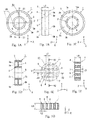
- Fig. 1 illustrates a mesh filter 1 according to a first embodiment of the present invention.
- Fig. 1A is a front view of the mesh filter 1
- Fig. 1B is a side view of the mesh filter 1
- Fig. 1C is a back view of the mesh filter 1
- Fig. 1D is a cross-sectional view of the mesh filter 1 taken along line A1-A1 in Fig. 1A.
- Fig. 1E is an enlarged view of a portion B1 of Fig. 1A (an enlarged view of part of the mesh filter 1)
- Fig. 1F is a cross-sectional view taken along line A2-A2 in Fig. 1E (a partly enlarged cross-sectional view of the mesh filter 1)
- Fig. 1G is a cross-sectional view taken along line A3-A3 in Fig. 1E (a partly enlarged cross-sectional view of the mesh filter 1).
- the mesh filter 1 integrally includes a cylindrical inner cylinder 2 (inner frame member), a cylindrical outer cylinder 3 concentric with the inner cylinder 2 (outer frame member surrounding the inner frame member), a filter unit 4 configured to connect an outer peripheral surface 2a of the inner cylinder 2 and an inner peripheral surface 3a of the outer cylinder 3 along a radial direction.
- the entire part of the mesh filter 1 is integrally formed of 66 nylon.
- the mesh filter 1 as described above is configured to be arranged, for example, in the fuel supply tube which is connected to a fuel injection device of an automotive vehicle, in such a manner that the inner cylinder 2 and the outer cylinder 3 are mounted on a fuel supply conduit or the like via a seal member (not illustrated), and is used so as not to cause leakage of fuel (fluid) passing through the filter unit 4.
- an outer diameter of the inner cylinder 2 is 10 mm
- an outer diameter of the outer cylinder 3 is 16 mm.
- a thickness of the inner cylinder 2 is 1 mm
- a thickness of the outer cylinder 3 is 1 mm.
- Numerical values relating to the inner cylinder 2 and the outer cylinder 3 are examples only, and may be changed as needed depending on use conditions and the like.
- the inner cylinder 2 and the outer cylinder 3 have the same lengthwise dimension L1 along a center axis 5, and both of one-end-surfaces 2b, 3b in a direction along the center axis 5 are located on the same virtual plane orthogonal to the center axis 5, and both of other-end-surfaces 2c, 3c in the direction along the center axis 5 are located on the same virtual plane orthogonal to the center axis 5.
- the relationship between the inner cylinder 2 and the outer cylinder 3 is not limited to that in the present embodiment, and may be configured to be deformed in association with a mounting state of the mesh filter 1 in such a manner that dimensions of the inner cylinder 2 and the outer cylinder 3 along the center axis 5 are differentiated, or the one-end-surface 2b of the inner cylinder 2 in a direction along the center axis 5 is located at a position shifted from the one-end-surface 3b of the outer cylinder 3 in a direction along the center axis 5.
- a configuration in which the other-end-surface 2c of the inner cylinder 2 in a direction along the center axis 5 is located at a position shifted from the other-end-surface 3c of the outer cylinder 3 in a direction along the center axis 5 is also applicable.
- the filter unit 4 is formed along the X-Y plane.
- a portion of the filter unit 4 other than a connecting portion between the inner cylinder 2 and the outer cylinder 3 is provided with a plurality of square-shaped openings 8 formed by a plurality of vertical ribs 6 formed equidistantly so as to be orthogonal to an X-axis and in parallel to a Y-axis, and a plurality of lateral ribs 7 formed equidistantly so as to be orthogonal to the vertical ribs 6 and in parallel with the X-axis.
- the openings 8 are each formed into a regular tetragon, 0.1 mm on a side.
- the vertical ribs 6 and the lateral ribs 7 are configured in such a manner that rib widths (L2, L3), which correspond to a dimension of a portion between openings 8, 8 adjacent to each other (a dimension L2 in a direction along the X-axis in Fig. 1E or a dimension L3 in a direction extending along the Y-axis in Fig.
- the filter unit 4 is formed to have a radial dimension L6 along the X-axis direction falling within a range of 2 to 5 mm as illustrated in Fig. 1A , and an optimal dimension is set in accordance with a structure of a mounting portion of the mesh filter 1 and the like.
- the filter unit 4 also includes openings of regular tetragon, 0.1 mm on a side at a connecting portion between the inner cylinder 2 and the outer cylinder 3.
- the filter unit 4 is formed in such a manner that center portions in a direction along the center axis 5 of the inner cylinder 2 and the outer cylinder 3 are connected in the radial direction.
- the filter unit 4 is not limited thereto, and the arrangement on the inner cylinder 2 and the outer cylinder 3 at positions shifted to one-ends in a direction along the center axis 5, and the arrangement on the inner cylinder 2 and the outer cylinder 3 at positions shifted to the other-ends in a direction along the center axis 5 are also applicable.
- Fig. 2 illustrates a mold 10 used for injection molding of the mesh filter 1 according to this embodiment.
- Fig. 2A is a vertical cross-sectional view of the mold 10
- Fig. 2B is an enlarged view of a portion B2 in Fig. 2A (a partly enlarged cross-sectional view of the mold 10)
- Fig. 2C is a plan view of part of a first mold 11 viewed in a direction D in Fig. 2B .
- the mold 10 is provided with a cavity 13 for injection-molding the mesh filter 1 on mating surface sides of the first mold 11 and a second mold 12.
- the cavity 13 includes a cylindrical first cavity portion 14 for forming the inner cylinder 2 of the mesh filter 1, a cylindrical second cavity portion 15 for forming the outer cylinder 3 of the mesh filter 1, and a hollow disc-shaped third cavity portion 16 for forming the filter unit 4 of the mesh filter 1.
- the first mold 11 includes pin gates 18 opening on a one-end-surface 14a side in a direction along a center axis 17 of the first cavity portion 14 provided equidistantly at six positions along a circumferential direction of the first cavity portion 14 (see gate scars 18a in Fig. 1 C) .
- a portion forming the third cavity portion 16 of the first mold 11 includes a plurality of (the same number as the number of the openings 8) projections 20 for forming the openings 8 formed equidistantly thereon (see Figs. 2B to 2C ).
- the projections 20 formed on a portion that forms the third cavity portion 16 of the first mold 11 each have a regular tetragonal shape (the shape viewed in the direction D in Fig. 2B ) in plan view, and are formed to have a dimension which can form the regular tetragonal openings 8 having a dimension L7 of 0.1 mm on a side.
- the projections 20 provided on a portion, which forms the third cavity portion 16 of the first mold 11, are formed so that the height thereof (a dimension L8 along the Z-axis direction of Fig. 2B ) becomes a thickness (0.3 mm) of the vertical ribs 6 and the lateral ribs 7.
- a mode in which the pin gates 18 opening to the cavity 13 are provided equidistantly at six positions along the circumferential direction of the first cavity portion 14 has been exemplified.
- the pin gates 18 are not limited thereto, and may be provided at a plurality of, at least two positions in accordance with an outer diameter of the first cavity portion 14. Ring gates may be provided instead of a plurality of the pin gates 18.
- the second mold 12 of the mold 10 in an opened state is moved in a +C direction (a direction approaching the first mold 11), the second mold 12 is pressed against the first mold 11, and the first mold 11 and the second mold 12 are closed.
- One cycle of the injection molding of the mesh filter 1 according to the present embodiment as described above is shorter than one cycle of an insert molding of the mesh filter 100 of the related art. Consequently, with the mesh filter 1 of the present embodiment, productivity is improved more than the mesh filter 100 of the related art, and a price as a product is lower than that of the mesh filter 100 of the related art.
- Fig. 2D is a drawing illustrating a first modification of the projections 20 for forming the openings 8.
- the projections 20 for forming the openings 8 may be formed only on a portion which forms the third cavity portion 16 of the second mold 12 instead of forming on a portion which forms the third cavity portion 16 of the first mold 11.
- Fig. 2E is a drawing illustrating a second modification of the projections 20 for forming the openings 8.
- the projections 20 for forming the openings 8 may be formed separately on the portion which forms the third cavity portion 16 of the first mold 11 and on the portion which forms the third cavity portion 16 of the second mold 12.
- the height of each of the projections 20A, 20B of the first mold 11 and the second mold 12 is formed to have 1/2 the height of the projections 20 in the above-described embodiment and the above-described first modification.
- top surfaces of the projections 20A and top surfaces of the projections 20B are butted with each other.
- 66 nylon (CM3001-N of Toray Industries, INC.) in a melted state is injected, so that the mesh filter 1 having the same shape as the shape of the cavity 13 is molded.
- An injection molding machine (not illustrated) used in the injection molding of the mesh filter 1 is an injection molding machine (S2000i 50B) manufactured by FANUC CORPORATION.
- the injection molding machine described above has a screw size of ⁇ 28, and a maximum injection pressure of 190 MPa.
- the injection molding of the mesh filter 1 according to the present embodiment using the injection molding machine was performed with the mold 10 at a temperature of 80°C, a cylinder temperature (nozzle portion temperature) of 300°C, an injection speed of 140 mm/sec, and an injection pressure of 124 MPa.
- the mold 10 described above and the injection molding machine described above are used, and 66 nylon in the melted state is injection molded under the injection molding conditions described above, so that the entire part (the inner cylinder 2, the outer cylinder 3, and the filter unit 4) is injection-molded integrally and at a high degree of accuracy without causing molding failures such as a short shot and the like, and thus productivity is improved and the price as a product is lowered in a state in which performances as a filter is maintained compared with the insert molding of the related art.
- the mesh filter 1 of the present embodiment includes the plurality of openings 8 of the filter unit 4 having the same dimension (regular tetragon, 0.1 mm on a side), for example, by being arranged in the fuel supply conduit connected to the fuel injection device of the automotive vehicle, foreign substances in a fuel having a diameter exceeding 0.1 mm can be filtered out, and the fuel from which the foreign substances are removed can be flowed out smoothly from the openings 8.
- the lowest values of the particle diameter of the foreign substances that can be filtered out by the filter unit may vary, and hence foreign substances which need to be passed through the filter unit may be filtered out, or foreign substances which need to be filtered out by the filter unit may be passed therethrough, so that insufficient filtering performances may result.
- the mesh filter 1 of the present embodiment the lowest values of the particle diameter of foreign substances that can be filtered out do not vary, so that the filter performances can be improved more than the case where the surface areas of the openings vary.
- the thicknesses (L4, L5) of the vertical ribs 6 and the lateral ribs 7 are the same (0.3 mm) over the entire area of the filter unit 4, for example, machining of the mold 10 is easier than the case where at least one of the thicknesses of the vertical ribs 6 and the lateral ribs 7 at a center portion of the filter unit 4 is formed to be the thickness of at least the one of the vertical ribs 6 and the lateral ribs 7 in other portions of the filter unit 4, and the cost of the mold 10 is lowered, and thus the price as a product can be lowered.
- the mesh filter 1 of the present embodiment since the thicknesses (L4, L5) of the vertical ribs 6 and the lateral ribs 7 are three times larger than the rib widths (L2, L3) of the vertical ribs 6 and the lateral ribs 7, rigidity of the filter unit 4 can be enhanced. Accordingly, with the mesh filter 1 of the present embodiment, separating property with respect to the mold is desirable, and also accuracy in shape of the filter unit 4 of the molded product can be enhanced.
- 66 nylon which corresponds to a thermoplastic resin
- the material is not limited thereto, and POM (polyacetal, for example, M450-44), which is a thermoplastic resin, can be used.
- the mesh filter 1 was injection-molded by using the POM
- the rib widths (L2, L3) of the vertical ribs 6 and the lateral ribs 7 were 0.1 mm and the thicknesses (L4, L5) of the vertical ribs 6 and the lateral ribs 7 were 0.2 mm
- the same mesh filter 1 as that of the first embodiment described above could be molded.
- the rib widths (L2, L3) of the vertical ribs 6 and the lateral ribs 7 were 0.07 mm and the thicknesses (L4, L5) of the vertical ribs 6 and the lateral ribs 7 were 0.4 mm
- the same mesh filter 1 as that of the first embodiment described above could be molded.
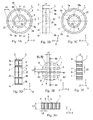
- Fig. 3 illustrates a mesh filter 1 according to a second embodiment of the present invention.
- the same parts of the mesh filter 1 of the present embodiment illustrated in Fig. 3 as the mesh filter 1 of the first embodiment are denoted by the same reference numerals and descriptions overlapped with the descriptions of the mesh filter 1 of the first embodiment will be omitted.
- the mesh filter 1 of the present embodiment includes a center-side filter unit 21 formed on a radially inside the inner cylinder 2 from the center axis 5 of the inner cylinder 2 to an inner peripheral surface 2d of the inner cylinder 2.
- the center-side filter unit 21 is formed in the same manner as the filter unit 4 of the mesh filter 1 of the first embodiment described above (see Fig. 1E and Fig. 3E ).
- an opening surface area of the openings 8 of the center-side filter unit 21 may be differentiated from that of the openings 8 of the filter unit 4 in accordance with the particle diameter of the foreign substances which are to be filtered out.
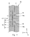
- Fig. 4 illustrates a mold 10 used for injection molding of the mesh filter 1 according to the present embodiment, and is a cross-sectional view corresponding to Fig. 2A .
- the same parts of the mold 10 illustrated in Fig. 4 as the mold 10 in Fig. 2 are denoted by the same reference signs, and descriptions overlapped with that of the mold 10 in Fig. 2 will be omitted.
- the mold 10 illustrated in Fig. 4 includes a fourth cavity portion 22 for forming the center-side filter unit 21 radially inside the first cavity portion 14 for forming the inner cylinder 2.
- thermoplastic resin in the melted state when the thermoplastic resin in the melted state is injected from the pin gates 18 opening to the first cavity portion 14, the thermoplastic resin in the melted state flows from the first cavity portion 14 toward the third cavity portion 16 and the fourth cavity portion 22, and the entire part (the inner cylinder 2, the outer cylinder 3, the filter unit 4, and the center-side filter unit 21) is injection-molded integrally with high-degree of accuracy.
- Fig. 5 illustrates a mesh filter 1 according to a third embodiment of the present invention (drawings corresponding to Fig. 1A and Fig. 3A ), and illustrates a modification of the mesh filters 1 according to the first and the second embodiments.
- Fig. 5A is a drawing illustrating a modification of the mesh filter 1 of the first embodiment
- Fig. 5B is a drawing illustrating a modification of the mesh filter 1 according to the second embodiment.
- shapes of the inner cylinder 2 and the outer cylinder 3 of the mesh filter 1 on the front side are formed into a regular hexagon.
- the shapes of the inner cylinder 2 and the outer cylinder 3 of the mesh filter 1 may be formed corresponding to the shapes of counterpart members (fuel conduit and the like) to be mounted thereto as long as leakage of fuel is prevented.
- the mesh filter 1 may be injection-molded, and shapes of the inner cylinder 2 and the outer cylinder 3 on the front side may be formed into polygonal shapes other than a regular pentagon as long as functions as the mesh filter are exhibited.
- the shapes of the inner cylinder 2 and the outer cylinder 3 may be different in such a manner that the shape of the inner cylinder 2 on the front side is a circle and the front shape of the outer cylinder 3 is a regular octagon.
- the mesh filter 1 of the present embodiment is exemplified in a mode of being installed in the fuel supply tube which is to be connected to the fuel injection device of the automotive vehicle
- the mesh filter 1 may be installed at a midpoint of an oil conduit such as a lubricating device or the like of the automotive vehicle as a matter of course.
- the mesh filter 1 is not limited thereto and may be installed in a conduit such as a water supply tube or a wind supply tube and used in a technical field of a wide range for removing foreign substances mixed in fluid (liquid such as water and gas such as air and the like).
- Reference Signs List 1 ... mesh filter, 2 ... inner cylinder, 2a ... outer surface, 2b ... one-end-surface, 3 ... outer cylinder, 3a ... inner surface, 4 ... filter unit, 5 ... center axis, 6 ... vertical rib, 7 ... lateral rib, 8 ... opening, 10 ... mold, 13 ... cavity, 18 ... pin gate, L2, L3 ... rib width, L4 ... thickness of vertical rib, L5 ... thickness of lateral rib
Landscapes
- Engineering & Computer Science (AREA)
- Chemical & Material Sciences (AREA)
- Mechanical Engineering (AREA)
- Chemical Kinetics & Catalysis (AREA)
- Manufacturing & Machinery (AREA)
- Combustion & Propulsion (AREA)
- Textile Engineering (AREA)
- General Engineering & Computer Science (AREA)
- Moulds For Moulding Plastics Or The Like (AREA)
- Injection Moulding Of Plastics Or The Like (AREA)
- Filtering Materials (AREA)
- Filtering Of Dispersed Particles In Gases (AREA)
- Filtration Of Liquid (AREA)
Abstract


Description
- The present invention relates to a mesh filter used for filtering out foreign substances in a fluid and, specifically, to a mesh filter integrally molded by injection molding.
- For example, a mesh filter is arranged at a midpoint of oil piping such as a fuel supply tube, a lubricating device, and the like to be connected to a fuel injection device of an automotive vehicle and foreign substances in fluid such as fuel or oil are filtered out with the mesh filter.
-
Fig. 6 illustrates amesh filter 100 of the related art.Fig. 6A is a plan view of themesh filter 100 of the related art, andFig. 6B is a cross-sectional view of themesh filter 100 taken along line A4-A4 inFig. 6A. Fig. 6C is a cross-sectional view of amold 101 for explaining a first stage of a method of molding themesh filter 100 of the related art,Fig. 6D is a cross-sectional view of themold 101 for explaining a second stage of the method of molding themesh filter 100 of the related art, andFig. 6E is an enlarged view of a B4 portion ofFig. 6A . - The
mesh filter 100 of the related art illustrated inFig. 6 includes amesh member 103 having a number of openings 102 (for example, square openings of 0.1 mm x 0.1 mm) configured to allow passage of oil and filter out foreign substances (metal powder, dust, and the like) having a predetermined size (for example, a diameter of 0.1 mm) and a resin-madeframe member 104 mounted on themesh member 103 along the peripheral edge thereof (seeFigs. 6A to 6B ). Themesh filter 100 has a shape in which themesh member 103 is stretched over the frame member 104 (seeFigs. 6A to 6B, 6E ). - The
mesh filter 100 configured in this manner of the related art is insert-molded as illustrated inFigs. 6C to 6D . Firstly, in a state in which afirst mold 105 and asecond mold 106 are opened, themesh member 103 is arranged on abase portion 108 in acavity 107 of the first mold 105 (Fig. 6C ). Subsequently, thesecond mold 106 is pressed against the first mold 105 (thefirst mold 105 and thesecond mold 106 are closed) and themesh member 103 is pinched between apressing portion 110 of thesecond mold 106 and thebase portion 108 of thefirst mold 105, and thecavity 107 for forming theframe member 104 is formed on mating surface sides of thefirst mold 105 and thesecond mold 106, and subsequently, melted resin is injected from a gate, which is not illustrated, into the cavity 107 (seeFig. 6D ), so that the resin-madeframe member 104 is integrally molded on the peripheral edge of the mesh member 103 (seePatent Literatures 1, 2). -
- PTL 1: JP-UM-A-5-44204
- PTL 2:
JP-A-2007-1232 - However, since the
mesh filter 100 of the related art as described above is manufactured by insert molding, the number of processes in manufacture is increased correspondingly to the number of processes required for installing themesh member 103 in a predetermined position of thecavity 107 compared with a case where an entire part is integrally molded by injection molding. Therefore, an improvement of the productivity of the mesh filter and lowering of a price of the mesh filter as a product by integrally molding the entire mesh filter by the injection molding while maintaining filter performances (performances which can remove foreign substances having diameters equal to or larger than a predetermined particle diameter) of themesh filter 100 of the related art have been demanded. - Accordingly, in order to respond to an industry's demand, it is an object of the present invention is to provide an injection-molded mesh filter capable of improving productivity and lowering the price of the product while maintaining required filter performances.
- As illustrated in
Fig. 1 to Fig. 5 , amesh filter 1 according to the present invention is configured to be capable of being mounted on a flow channel for filtering out foreign substances in a fluid. Themesh filter 1 according to the present invention includes aninner cylinder 2, anouter cylinder 3 configured to surround theinner cylinder 2, and afilter unit 4 configured to connect an outerperipheral surface 2a of theinner cylinder 2 and an innerperipheral surface 3a of theouter cylinder 3 along a radial direction of theinner cylinder 2. Assuming a virtual plane orthogonal to acenter axis 5 of theinner cylinder 2 to be an X-Y plane, thefilter unit 4 is formed along the X-Y plane. A portion of thefilter unit 4 other than a connecting portion between theinner cylinder 2 and theouter cylinder 3 is provided with a plurality of square-shaped openings 8 formed by a plurality ofvertical ribs 6 formed equidistantly so as to be orthogonal to an X-axis and in parallel to a Y-axis, and a plurality oflateral ribs 7 formed equidistantly so as to be orthogonal to thevertical ribs 6 and in parallel with the X-axis. Rib widths (L2, L3), which are dimensions betweenadjacent openings vertical ribs 6 and thelateral ribs 7 fall within a range from 0.07 mm to 0.1 mm, and thicknesses (L4, L5) thereof, which are dimensions in a direction along thecenter axis 5 of theinner cylinder 2, fall within a range from 0.2 mm to 0.4 mm. Themesh filter 1 of the present invention includes theinner cylinder 2, theouter cylinder 3, and thefilter unit 4 molded integrally by injecting a thermoplastic resin in a melted state from agate 18 opening at a cavity portion out of acavity 13 of a mold 10 (a first cavity portion 14), which forms theinner cylinder 2, into the cavity portion. - According to the present invention, the entire part of the mesh filter can be integrally molded by the injection molding, and thus an improvement of the productivity of the mesh filter and lowering of a price as a product of the mesh filter are achieved while maintaining filter performances of the mesh filter.
-
- [
Fig. 1] Fig. 1 illustrates a mesh filter according to a first embodiment of the present invention, in whichFig. 1A is a front view of the mesh filter,Fig. 1B is a side view of the mesh filter,Fig. 1C is a back view of the mesh filter,Fig. 1D is a cross-sectional view of the mesh filter taken along line A1-A1 inFig. 1A, Fig. 1 E is an enlarged view of a portion B1 inFig. 1A, Fig. 1F is a cross-sectional view taken along line A2-A2 inFig. 1E, and Fig. 1G is a cross-sectional view taken along line A3-A3 inFig. 1E . - [
Fig. 2] Fig. 2 illustrates a mold used for injection molding of the mesh filter according to the first embodiment of the present invention, in whichFig. 2A is a vertical cross-sectional view of the mold,Fig. 2B is an enlarged view of a portion B2 inFig. 2A, Fig. 2C is a plan view of part of a first mold viewed in a direction D inFig. 2B, Fig. 2D is a drawing illustrating a first modification of projections that form openings (a drawing corresponding toFig. 2B), and Fig. 2E is a drawing illustrating a second modification of projections that form openings (a drawing corresponding toFig. 2B ). - [
Fig. 3] Fig. 3 illustrates a mesh filter according to a second embodiment of the present invention, in whichFig. 3A is a front view of the mesh filter,Fig. 3B is a side view of the mesh filter,Fig. 3C is a back view of the mesh filter,Fig. 3D is a cross-sectional view of the mesh filter taken along line A1-A1 inFig. 3A, Fig. 3E is an enlarged view of a portion B1 inFig. 3A, Fig. 3F is a cross-sectional view taken along line A2-A2 inFig. 3E, and Fig. 3G is a cross-sectional view taken along line A3-A3 inFig. 3E . - [
Fig. 4] Fig. 4 is a cross-sectional view illustrating a mold used for injection molding of the mesh filter according to the second embodiment of the present invention, corresponding toFig. 2A . - [
Fig. 5] Fig. 5 illustrates a mesh filter according to a third embodiment of the present invention (drawings corresponding toFig. 1A andFig. 3A ), and illustrates a modification of the mesh filters according to the first and the second embodiments. - [
Fig. 6] Fig. 6 illustrates a mesh filter of the related art, in whichFig. 6A is a plan view of the mesh filter of the related art,Fig. 6B is a cross-sectional view taken along line A4-A4 inFig. 6A, Fig. 6C is a cross-sectional view of a mold for explaining a first stage in a method of molding a mesh filter of the related art,Fig. 6D is a cross-sectional view of a mold for explaining a second stage in a method of molding the mesh filter of the related art, andFig. 6E is an enlarged view of a portion B4 inFig. 6A . - Embodiments of the present invention will be described in detail below with reference to the drawings.
-
Fig. 1 illustrates amesh filter 1 according to a first embodiment of the present invention.Fig. 1A is a front view of themesh filter 1,Fig. 1B is a side view of themesh filter 1,Fig. 1C is a back view of themesh filter 1, andFig. 1D is a cross-sectional view of themesh filter 1 taken along line A1-A1 inFig. 1A. Fig. 1E is an enlarged view of a portion B1 ofFig. 1A (an enlarged view of part of the mesh filter 1),Fig. 1F is a cross-sectional view taken along line A2-A2 inFig. 1E (a partly enlarged cross-sectional view of the mesh filter 1), andFig. 1G is a cross-sectional view taken along line A3-A3 inFig. 1E (a partly enlarged cross-sectional view of the mesh filter 1). - As illustrated in
Fig. 1 , themesh filter 1 integrally includes a cylindrical inner cylinder 2 (inner frame member), a cylindricalouter cylinder 3 concentric with the inner cylinder 2 (outer frame member surrounding the inner frame member), afilter unit 4 configured to connect an outerperipheral surface 2a of theinner cylinder 2 and an innerperipheral surface 3a of theouter cylinder 3 along a radial direction. The entire part of themesh filter 1 is integrally formed of 66 nylon. Themesh filter 1 as described above is configured to be arranged, for example, in the fuel supply tube which is connected to a fuel injection device of an automotive vehicle, in such a manner that theinner cylinder 2 and theouter cylinder 3 are mounted on a fuel supply conduit or the like via a seal member (not illustrated), and is used so as not to cause leakage of fuel (fluid) passing through thefilter unit 4. In the present embodiment, an outer diameter of theinner cylinder 2 is 10 mm, and an outer diameter of theouter cylinder 3 is 16 mm. A thickness of theinner cylinder 2 is 1 mm, and a thickness of theouter cylinder 3 is 1 mm. Numerical values relating to theinner cylinder 2 and theouter cylinder 3 are examples only, and may be changed as needed depending on use conditions and the like. - The
inner cylinder 2 and theouter cylinder 3 have the same lengthwise dimension L1 along acenter axis 5, and both of one-end-surfaces center axis 5 are located on the same virtual plane orthogonal to thecenter axis 5, and both of other-end-surfaces center axis 5 are located on the same virtual plane orthogonal to thecenter axis 5. The relationship between theinner cylinder 2 and theouter cylinder 3 is not limited to that in the present embodiment, and may be configured to be deformed in association with a mounting state of themesh filter 1 in such a manner that dimensions of theinner cylinder 2 and theouter cylinder 3 along thecenter axis 5 are differentiated, or the one-end-surface 2b of theinner cylinder 2 in a direction along thecenter axis 5 is located at a position shifted from the one-end-surface 3b of theouter cylinder 3 in a direction along thecenter axis 5. A configuration in which the other-end-surface 2c of theinner cylinder 2 in a direction along thecenter axis 5 is located at a position shifted from the other-end-surface 3c of theouter cylinder 3 in a direction along thecenter axis 5 is also applicable. - Assuming a virtual plane orthogonal to a direction extending along the
center axis 5 of theinner cylinder 2 to be an X-Y plane, thefilter unit 4 is formed along the X-Y plane. A portion of thefilter unit 4 other than a connecting portion between theinner cylinder 2 and theouter cylinder 3 is provided with a plurality of square-shapedopenings 8 formed by a plurality ofvertical ribs 6 formed equidistantly so as to be orthogonal to an X-axis and in parallel to a Y-axis, and a plurality oflateral ribs 7 formed equidistantly so as to be orthogonal to thevertical ribs 6 and in parallel with the X-axis. Theopenings 8 are each formed into a regular tetragon, 0.1 mm on a side. Thevertical ribs 6 and thelateral ribs 7 are configured in such a manner that rib widths (L2, L3), which correspond to a dimension of a portion betweenopenings Fig. 1E or a dimension L3 in a direction extending along the Y-axis inFig. 1 E) are 0.1 mm, and thicknesses (L4, L5) of thevertical ribs 6 and thelateral ribs 7, which correspond to dimensions L4, L5 of thevertical ribs 6 and thelateral ribs 7 in a direction along thecenter axis 5 of the inner cylinder 2 (a Z-axis direction inFig. 1F or a Z-axis direction inFig. 1G ) are 0.3 mm. Thefilter unit 4 is formed to have a radial dimension L6 along the X-axis direction falling within a range of 2 to 5 mm as illustrated inFig. 1A , and an optimal dimension is set in accordance with a structure of a mounting portion of themesh filter 1 and the like. Thefilter unit 4 also includes openings of regular tetragon, 0.1 mm on a side at a connecting portion between theinner cylinder 2 and theouter cylinder 3. Thefilter unit 4 is formed in such a manner that center portions in a direction along thecenter axis 5 of theinner cylinder 2 and theouter cylinder 3 are connected in the radial direction. However, thefilter unit 4 is not limited thereto, and the arrangement on theinner cylinder 2 and theouter cylinder 3 at positions shifted to one-ends in a direction along thecenter axis 5, and the arrangement on theinner cylinder 2 and theouter cylinder 3 at positions shifted to the other-ends in a direction along thecenter axis 5 are also applicable. -
Fig. 2 illustrates amold 10 used for injection molding of themesh filter 1 according to this embodiment. InFig. 2, Fig. 2A is a vertical cross-sectional view of themold 10,Fig. 2B is an enlarged view of a portion B2 inFig. 2A (a partly enlarged cross-sectional view of the mold 10), andFig. 2C is a plan view of part of afirst mold 11 viewed in a direction D inFig. 2B . - As illustrated in
Fig. 2A , themold 10 is provided with acavity 13 for injection-molding themesh filter 1 on mating surface sides of thefirst mold 11 and asecond mold 12. Thecavity 13 includes a cylindricalfirst cavity portion 14 for forming theinner cylinder 2 of themesh filter 1, a cylindricalsecond cavity portion 15 for forming theouter cylinder 3 of themesh filter 1, and a hollow disc-shapedthird cavity portion 16 for forming thefilter unit 4 of themesh filter 1. Thefirst mold 11 includespin gates 18 opening on a one-end-surface 14a side in a direction along acenter axis 17 of thefirst cavity portion 14 provided equidistantly at six positions along a circumferential direction of the first cavity portion 14 (seegate scars 18a inFig. 1 C) . A portion forming thethird cavity portion 16 of thefirst mold 11 includes a plurality of (the same number as the number of the openings 8)projections 20 for forming theopenings 8 formed equidistantly thereon (seeFigs. 2B to 2C ). Theprojections 20 formed on a portion that forms thethird cavity portion 16 of thefirst mold 11 each have a regular tetragonal shape (the shape viewed in the direction D inFig. 2B ) in plan view, and are formed to have a dimension which can form the regulartetragonal openings 8 having a dimension L7 of 0.1 mm on a side. Theprojections 20 provided on a portion, which forms thethird cavity portion 16 of thefirst mold 11, are formed so that the height thereof (a dimension L8 along the Z-axis direction ofFig. 2B ) becomes a thickness (0.3 mm) of thevertical ribs 6 and thelateral ribs 7. In the present embodiment, a mode in which thepin gates 18 opening to thecavity 13 are provided equidistantly at six positions along the circumferential direction of thefirst cavity portion 14 has been exemplified. However, thepin gates 18 are not limited thereto, and may be provided at a plurality of, at least two positions in accordance with an outer diameter of thefirst cavity portion 14. Ring gates may be provided instead of a plurality of thepin gates 18. - With the
mold 10 having the structure as described above, as illustrated inFig. 2A , in a state in which thefirst mold 11 and thesecond mold 12 are closed, 66 nylon in a melted state is injected into thecavity 13 from the plurality ofpin gates 18, then the pressure in thecavity 13 is maintained at a predetermined pressure, and then themold 10 is cooled. Subsequently, thesecond mold 12 is separated (opened) from thefirst mold 11 in a -C direction, themesh filter 1 in thecavity 13 is pushed out from the interior of thecavity 13 by an ejector pin, which is not illustrated, so that themesh filter 1, which corresponds to an injection molding product, is taken out from the mold 10 (seeFig. 1 ). Subsequently, thesecond mold 12 of themold 10 in an opened state is moved in a +C direction (a direction approaching the first mold 11), thesecond mold 12 is pressed against thefirst mold 11, and thefirst mold 11 and thesecond mold 12 are closed. One cycle of the injection molding of themesh filter 1 according to the present embodiment as described above is shorter than one cycle of an insert molding of themesh filter 100 of the related art. Consequently, with themesh filter 1 of the present embodiment, productivity is improved more than themesh filter 100 of the related art, and a price as a product is lower than that of themesh filter 100 of the related art. -
Fig. 2D is a drawing illustrating a first modification of theprojections 20 for forming theopenings 8. As illustrated inFig. 2D , theprojections 20 for forming theopenings 8 may be formed only on a portion which forms thethird cavity portion 16 of thesecond mold 12 instead of forming on a portion which forms thethird cavity portion 16 of thefirst mold 11. -
Fig. 2E is a drawing illustrating a second modification of theprojections 20 for forming theopenings 8. As illustrated inFig. 2E , theprojections 20 for forming theopenings 8 may be formed separately on the portion which forms thethird cavity portion 16 of thefirst mold 11 and on the portion which forms thethird cavity portion 16 of thesecond mold 12. In the second modification, the height of each of theprojections first mold 11 and thesecond mold 12 is formed to have 1/2 the height of theprojections 20 in the above-described embodiment and the above-described first modification. At the time of closing thefirst mold 11 and thesecond mold 12, top surfaces of theprojections 20A and top surfaces of theprojections 20B are butted with each other. - In the interior of the
cavity 13 of themold 10 configured as descried above, 66 nylon (CM3001-N of Toray Industries, INC.) in a melted state is injected, so that themesh filter 1 having the same shape as the shape of thecavity 13 is molded. An injection molding machine (not illustrated) used in the injection molding of themesh filter 1 is an injection molding machine (S2000i 50B) manufactured by FANUC CORPORATION. The injection molding machine described above has a screw size of ϕ 28, and a maximum injection pressure of 190 MPa. - The injection molding of the
mesh filter 1 according to the present embodiment using the injection molding machine was performed with themold 10 at a temperature of 80°C, a cylinder temperature (nozzle portion temperature) of 300°C, an injection speed of 140 mm/sec, and an injection pressure of 124 MPa. - With the
mesh filter 1 of the present embodiment as described above, themold 10 described above and the injection molding machine described above are used, and 66 nylon in the melted state is injection molded under the injection molding conditions described above, so that the entire part (theinner cylinder 2, theouter cylinder 3, and the filter unit 4) is injection-molded integrally and at a high degree of accuracy without causing molding failures such as a short shot and the like, and thus productivity is improved and the price as a product is lowered in a state in which performances as a filter is maintained compared with the insert molding of the related art. - Since the
mesh filter 1 of the present embodiment includes the plurality ofopenings 8 of thefilter unit 4 having the same dimension (regular tetragon, 0.1 mm on a side), for example, by being arranged in the fuel supply conduit connected to the fuel injection device of the automotive vehicle, foreign substances in a fuel having a diameter exceeding 0.1 mm can be filtered out, and the fuel from which the foreign substances are removed can be flowed out smoothly from theopenings 8. With the mesh filter in which the surface areas of the openings are not formed to be the same over the entire area of the filter unit, the lowest values of the particle diameter of the foreign substances that can be filtered out by the filter unit may vary, and hence foreign substances which need to be passed through the filter unit may be filtered out, or foreign substances which need to be filtered out by the filter unit may be passed therethrough, so that insufficient filtering performances may result. However, with themesh filter 1 of the present embodiment, the lowest values of the particle diameter of foreign substances that can be filtered out do not vary, so that the filter performances can be improved more than the case where the surface areas of the openings vary. - With the
mesh filter 1 of the present embodiment, since the thicknesses (L4, L5) of thevertical ribs 6 and thelateral ribs 7 are the same (0.3 mm) over the entire area of thefilter unit 4, for example, machining of themold 10 is easier than the case where at least one of the thicknesses of thevertical ribs 6 and thelateral ribs 7 at a center portion of thefilter unit 4 is formed to be the thickness of at least the one of thevertical ribs 6 and thelateral ribs 7 in other portions of thefilter unit 4, and the cost of themold 10 is lowered, and thus the price as a product can be lowered. - With the
mesh filter 1 of the present embodiment, since the thicknesses (L4, L5) of thevertical ribs 6 and thelateral ribs 7 are three times larger than the rib widths (L2, L3) of thevertical ribs 6 and thelateral ribs 7, rigidity of thefilter unit 4 can be enhanced. Accordingly, with themesh filter 1 of the present embodiment, separating property with respect to the mold is desirable, and also accuracy in shape of thefilter unit 4 of the molded product can be enhanced. - In the
mesh filter 1 of the first embodiment described above, 66 nylon, which corresponds to a thermoplastic resin, is used as the material for injection molding. However, the material is not limited thereto, and POM (polyacetal, for example, M450-44), which is a thermoplastic resin, can be used. - In the case where the
mesh filter 1 was injection-molded by using the POM, when the rib widths (L2, L3) of thevertical ribs 6 and thelateral ribs 7 were 0.1 mm and the thicknesses (L4, L5) of thevertical ribs 6 and thelateral ribs 7 were 0.2 mm, thesame mesh filter 1 as that of the first embodiment described above could be molded. In addition, when the rib widths (L2, L3) of thevertical ribs 6 and thelateral ribs 7 were 0.07 mm and the thicknesses (L4, L5) of thevertical ribs 6 and thelateral ribs 7 were 0.4 mm, thesame mesh filter 1 as that of the first embodiment described above could be molded. -
Fig. 3 illustrates amesh filter 1 according to a second embodiment of the present invention. The same parts of themesh filter 1 of the present embodiment illustrated inFig. 3 as themesh filter 1 of the first embodiment are denoted by the same reference numerals and descriptions overlapped with the descriptions of themesh filter 1 of the first embodiment will be omitted. - The
mesh filter 1 of the present embodiment includes a center-side filter unit 21 formed on a radially inside theinner cylinder 2 from thecenter axis 5 of theinner cylinder 2 to an innerperipheral surface 2d of theinner cylinder 2. The center-side filter unit 21 is formed in the same manner as thefilter unit 4 of themesh filter 1 of the first embodiment described above (seeFig. 1E andFig. 3E ). According to themesh filter 1 of the present embodiment, in the case where the particle diameter of foreign substances which are to be filtered out by the center-side filter unit 21 and the particle diameter of foreign substances which are to be filtered out by thefilter unit 4 are different from each other, an opening surface area of theopenings 8 of the center-side filter unit 21 may be differentiated from that of theopenings 8 of thefilter unit 4 in accordance with the particle diameter of the foreign substances which are to be filtered out. -
Fig. 4 illustrates amold 10 used for injection molding of themesh filter 1 according to the present embodiment, and is a cross-sectional view corresponding toFig. 2A . The same parts of themold 10 illustrated inFig. 4 as themold 10 inFig. 2 are denoted by the same reference signs, and descriptions overlapped with that of themold 10 inFig. 2 will be omitted. - The
mold 10 illustrated inFig. 4 includes afourth cavity portion 22 for forming the center-side filter unit 21 radially inside thefirst cavity portion 14 for forming theinner cylinder 2. - According to the
mold 10 of the present embodiment described above, when the thermoplastic resin in the melted state is injected from thepin gates 18 opening to thefirst cavity portion 14, the thermoplastic resin in the melted state flows from thefirst cavity portion 14 toward thethird cavity portion 16 and thefourth cavity portion 22, and the entire part (theinner cylinder 2, theouter cylinder 3, thefilter unit 4, and the center-side filter unit 21) is injection-molded integrally with high-degree of accuracy. -
Fig. 5 illustrates amesh filter 1 according to a third embodiment of the present invention (drawings corresponding toFig. 1A andFig. 3A ), and illustrates a modification of the mesh filters 1 according to the first and the second embodiments.Fig. 5A is a drawing illustrating a modification of themesh filter 1 of the first embodiment, andFig. 5B is a drawing illustrating a modification of themesh filter 1 according to the second embodiment. - As illustrated in
Fig. 5 , shapes of theinner cylinder 2 and theouter cylinder 3 of themesh filter 1 on the front side are formed into a regular hexagon. In this manner, the shapes of theinner cylinder 2 and theouter cylinder 3 of themesh filter 1 may be formed corresponding to the shapes of counterpart members (fuel conduit and the like) to be mounted thereto as long as leakage of fuel is prevented. Themesh filter 1 may be injection-molded, and shapes of theinner cylinder 2 and theouter cylinder 3 on the front side may be formed into polygonal shapes other than a regular pentagon as long as functions as the mesh filter are exhibited. The shapes of theinner cylinder 2 and theouter cylinder 3 may be different in such a manner that the shape of theinner cylinder 2 on the front side is a circle and the front shape of theouter cylinder 3 is a regular octagon. - Although the
mesh filter 1 of the present embodiment is exemplified in a mode of being installed in the fuel supply tube which is to be connected to the fuel injection device of the automotive vehicle, themesh filter 1 may be installed at a midpoint of an oil conduit such as a lubricating device or the like of the automotive vehicle as a matter of course. Alternatively, themesh filter 1 is not limited thereto and may be installed in a conduit such as a water supply tube or a wind supply tube and used in a technical field of a wide range for removing foreign substances mixed in fluid (liquid such as water and gas such as air and the like). -
Reference Signs List 1 ... mesh filter, 2 ... inner cylinder, 2a ... outer surface, 2b ... one-end-surface, 3 ... outer cylinder, 3a ... inner surface, 4 ... filter unit, 5 ... center axis, 6 ... vertical rib, 7 ... lateral rib, 8 ... opening, 10 ... mold, 13 ... cavity, 18 ... pin gate, L2, L3 ... rib width, L4 ... thickness of vertical rib, L5 ... thickness of lateral rib
Claims (3)
- A mesh filter used for filtering out foreign substances in fluid comprising:an inner cylinder;an outer cylinder surrounding the inner cylinder; anda filter unit configured to connect an outer peripheral surface of the inner cylinder and an inner peripheral surface of the outer cylinder along a radial direction of the inner cylinder,assuming a virtual plane orthogonal to a center axis of the inner cylinder to be an X-Y plane, the filter unit is formed along the X-Y plane,a portion of the filter unit other than a connecting portion between the inner cylinder and the outer cylinder is provided with a plurality of square-shaped openings formed by a plurality of vertical ribs formed equidistantly so as to be orthogonal to an X-axis and in parallel to a Y-axis, and a plurality of lateral ribs formed equidistantly so as to be orthogonal to the vertical ribs and in parallel with the X-axis,rib widths, which are dimensions between adjacent openings of the vertical ribs and the lateral ribs fall within a range from 0.07 mm to 0.1 mm, and thicknesses, which are dimensions in a direction along the center axis of the inner cylinder, thereof fall within a range from 0.2 mm to 0.4 mm, andthe inner cylinder, the outer cylinder, and the filter unit are molded integrally by injecting a thermoplastic resin in a melted state from a gate opening at a cavity portion of a cavity of the mold, which forms the inner cylinder, into the cavity portion.
- A mesh filter used for filtering out foreign substances in fluid comprising:a cylindrical inner cylinder;a cylindrical outer cylinder being concentric with the inner cylinder, anda filter unit configured to connect an outer peripheral surface of the inner cylinder and an inner peripheral surface of the outer cylinder along a radial direction of the inner cylinder,assuming a virtual plane orthogonal to a center axis of the inner cylinder to be an X-Y plane, the filter unit is formed along the X-Y plane,a portion of the filter unit other than a connecting portion between the inner cylinder and the outer cylinder is provided with a plurality of square-shaped openings formed by a plurality of vertical ribs formed equidistantly so as to be orthogonal to an X-axis and in parallel to a Y-axis, and a plurality of lateral ribs formed equidistantly so as to be orthogonal to the vertical ribs and in parallel with the X-axis,the opening is a regular tetragon, 0.1 mm on a side,rib widths, which are dimensions between adjacent openings of the vertical ribs and the lateral ribs are 0.1 mm, and thicknesses, which are dimensions in a direction along the center axis of the inner cylinder, thereof are 0.3 mm, andthe inner cylinder, the outer cylinder, and the filter unit are molded integrally by injecting 66 nylon in a melted state from a gate opening at a cavity portion of a cavity of a mold, which forms the inner cylinder, into the cavity portion.
- The mesh filter according to Claim 1, comprising a center-side filter unit extending from a center axis of the inner cylinder to an inner peripheral surface of the inner cylinder,
assuming a virtual plane orthogonal to a center axis of the inner cylinder to be an X-Y plane, the center-side filter unit is formed along the X-Y plane,
a portion of the center-side filter unit other than a connecting portion with respect to the inner cylinder is provided with a plurality of square-shaped openings formed by a plurality of vertical ribs formed equidistantly so as to be orthogonal to an X-axis and in parallel to a Y-axis, and a plurality of lateral ribs formed equidistantly so as to be orthogonal to the vertical ribs and in parallel with the X-axis,
rib widths, which are dimensions between adjacent openings of the vertical ribs and the lateral ribs fall within a range from 0.07 mm to 0.1 mm, and thicknesses, which are dimensions in a direction along the center axis of the inner cylinder, thereof fall within a range from 0.2 mm to 0.4 mm, and
the inner cylinder, the outer cylinder, the filter unit, and the center-side filter unit are molded integrally by injecting a thermoplastic resin in a melted state from a gate opening at a cavity portion of a cavity of a mold, which forms the inner cylinder, into the cavity portion.
Applications Claiming Priority (3)
| Application Number | Priority Date | Filing Date | Title |
|---|---|---|---|
| JP2013170297 | 2013-08-20 | ||
| JP2013182879A JP6254794B2 (en) | 2013-08-20 | 2013-09-04 | Mesh filter |
| PCT/JP2014/068679 WO2015025639A1 (en) | 2013-08-20 | 2014-07-14 | Mesh filter |
Publications (3)
| Publication Number | Publication Date |
|---|---|
| EP3037238A1 true EP3037238A1 (en) | 2016-06-29 |
| EP3037238A4 EP3037238A4 (en) | 2017-03-22 |
| EP3037238B1 EP3037238B1 (en) | 2019-10-02 |
Family
ID=52483421
Family Applications (1)
| Application Number | Title | Priority Date | Filing Date |
|---|---|---|---|
| EP14838343.3A Active EP3037238B1 (en) | 2013-08-20 | 2014-07-14 | Mesh filter |
Country Status (5)
| Country | Link |
|---|---|
| US (1) | US10293282B2 (en) |
| EP (1) | EP3037238B1 (en) |
| JP (1) | JP6254794B2 (en) |
| CN (1) | CN105451957B (en) |
| WO (1) | WO2015025639A1 (en) |
Cited By (4)
| Publication number | Priority date | Publication date | Assignee | Title |
|---|---|---|---|---|
| EP3081362A4 (en) * | 2013-12-13 | 2017-08-09 | Enplas Corporation | Mesh filter |
| EP3263309A4 (en) * | 2015-02-23 | 2018-09-19 | Enplas Corporation | Injection molding die for mesh filter and injection molding method for mesh filter |
| EP3342576A4 (en) * | 2015-08-26 | 2019-04-03 | Enplas Corporation | INJECTION MOLDING METHOD FOR MESH FILTER, INJECTION MOLDING MOLD AND MESH FILTER |
| DE102024137500B3 (en) | 2024-12-12 | 2026-05-07 | Andreas Stihl Ag & Co. Kg | Filter component for filtering cooling air for a hand-held work device and method for manufacturing such a filter component |
Families Citing this family (5)
| Publication number | Priority date | Publication date | Assignee | Title |
|---|---|---|---|---|
| BR112017005822B1 (en) * | 2014-09-22 | 2022-08-16 | Gvs S.P.A | METHOD TO PRODUCE AN IMPROVED FILTER FOR FUEL INJECTORS, OILS, SOLUTIONS, ADDITIVES AND FLUIDS IN GENERAL AND FILTER THUS PRODUCED |
| JP6522407B2 (en) * | 2015-04-24 | 2019-05-29 | 株式会社エンプラス | Mesh filter and method of manufacturing the same |
| JP6778013B2 (en) * | 2016-05-11 | 2020-10-28 | 株式会社エンプラス | Mesh filter |
| CN109529485A (en) * | 2018-10-16 | 2019-03-29 | 上海交通大学 | Air purifier for pressurized cabin of ship filters box |
| JP2020089802A (en) | 2018-12-03 | 2020-06-11 | 株式会社エンプラス | Cartridge with filter |
Family Cites Families (20)
| Publication number | Priority date | Publication date | Assignee | Title |
|---|---|---|---|---|
| JPS58122526A (en) | 1982-01-16 | 1983-07-21 | Porarisu:Kk | Picture synthesizing slide projector |
| JPS6031319U (en) * | 1983-08-05 | 1985-03-02 | 五葉工業株式会社 | plastic filter element |
| US4773990A (en) * | 1986-10-15 | 1988-09-27 | Filmax, Inc. | Axial flow filter having entry and exit filtration stages and flow distribution means |
| US4911840A (en) * | 1988-11-30 | 1990-03-27 | Ametek, Inc., Plymouth Products Division | Water conditioning apparatus |
| JPH0649308B2 (en) * | 1989-08-22 | 1994-06-29 | 大生産業株式会社 | Method for manufacturing filter and mold for manufacturing filter |
| JPH0544204A (en) | 1991-08-09 | 1993-02-23 | Shibata Ind Co Ltd | Breakwater |
| JPH07137166A (en) * | 1993-11-16 | 1995-05-30 | Daisan Kanagata Seisakusho:Kk | Plastic filter and mold therefor |
| JPH07300889A (en) * | 1994-03-07 | 1995-11-14 | Daizo Kotaki | Plastic filter for drain port |
| JPH07284617A (en) * | 1994-04-16 | 1995-10-31 | Daizo Kotaki | Plastic filter and plastic material feed passage structure |
| JP2711632B2 (en) * | 1994-05-31 | 1998-02-10 | 日精樹脂工業株式会社 | Injection molding method and mold for reticulated products |
| JP2912853B2 (en) * | 1995-06-20 | 1999-06-28 | 日精樹脂工業株式会社 | Molding method and molding die for reticulated products with synthetic resin |
| EP0861714B1 (en) * | 1997-02-28 | 2001-11-07 | Yamakawa Industrial Co. | Composite molded product, production process and apparatus therefor |
| DE19744361A1 (en) * | 1997-09-24 | 1999-03-25 | Theo Hillers | Plastic fuel filter |
| JP2002086510A (en) * | 2000-09-09 | 2002-03-26 | Daisan Kanagata Seisakusho:Kk | Mold for mesh filter and molded product |
| DE102004002963A1 (en) * | 2003-06-27 | 2005-01-13 | Friedrich Sanner Gmbh & Co Kg Spritzgusswerk | Component made from a thermoplastic material for sieving machines has a sieving or grid structure formed by two groups of parallel ribs which extend over a partial region |
| US20060049099A1 (en) * | 2004-09-03 | 2006-03-09 | Chang Jen C | Filter device used in a paint cup of a spraying gun |
| CA2481143A1 (en) * | 2004-09-10 | 2006-03-10 | Axiom Group Inc. | Plastic filter |
| US7718167B2 (en) * | 2004-09-13 | 2010-05-18 | Hynes Richard A | Method for treating wounds exposing the dura using PPP and PRP |
| JP4819416B2 (en) | 2005-06-27 | 2011-11-24 | 株式会社パイオラックス | Method for producing mesh filter and injection mold for producing mesh filter |
| JP5368914B2 (en) * | 2009-09-03 | 2013-12-18 | ダイキョーニシカワ株式会社 | Oil strainer manufacturing method |
-
2013
- 2013-09-04 JP JP2013182879A patent/JP6254794B2/en active Active
-
2014
- 2014-07-14 WO PCT/JP2014/068679 patent/WO2015025639A1/en not_active Ceased
- 2014-07-14 CN CN201480045469.5A patent/CN105451957B/en active Active
- 2014-07-14 US US14/912,712 patent/US10293282B2/en active Active
- 2014-07-14 EP EP14838343.3A patent/EP3037238B1/en active Active
Non-Patent Citations (1)
| Title |
|---|
| See references of WO2015025639A1 * |
Cited By (5)
| Publication number | Priority date | Publication date | Assignee | Title |
|---|---|---|---|---|
| EP3081362A4 (en) * | 2013-12-13 | 2017-08-09 | Enplas Corporation | Mesh filter |
| EP3263309A4 (en) * | 2015-02-23 | 2018-09-19 | Enplas Corporation | Injection molding die for mesh filter and injection molding method for mesh filter |
| EP3342576A4 (en) * | 2015-08-26 | 2019-04-03 | Enplas Corporation | INJECTION MOLDING METHOD FOR MESH FILTER, INJECTION MOLDING MOLD AND MESH FILTER |
| US10611069B2 (en) | 2015-08-26 | 2020-04-07 | Enplas Corporation | Injection-molding method for mesh filter, injection-molding mold, and mesh filter |
| DE102024137500B3 (en) | 2024-12-12 | 2026-05-07 | Andreas Stihl Ag & Co. Kg | Filter component for filtering cooling air for a hand-held work device and method for manufacturing such a filter component |
Also Published As
| Publication number | Publication date |
|---|---|
| CN105451957B (en) | 2018-06-15 |
| JP6254794B2 (en) | 2017-12-27 |
| US20160199758A1 (en) | 2016-07-14 |
| EP3037238A4 (en) | 2017-03-22 |
| WO2015025639A1 (en) | 2015-02-26 |
| JP2015061742A (en) | 2015-04-02 |
| EP3037238B1 (en) | 2019-10-02 |
| US10293282B2 (en) | 2019-05-21 |
| CN105451957A (en) | 2016-03-30 |
Similar Documents
| Publication | Publication Date | Title |
|---|---|---|
| EP3037238B1 (en) | Mesh filter | |
| US20180078881A1 (en) | Mesh filter | |
| JP6305116B2 (en) | Mesh filter | |
| JP6366302B2 (en) | Mesh filter | |
| JP6778013B2 (en) | Mesh filter | |
| JP6381385B2 (en) | Tubular mesh filter | |
| EP3342576A1 (en) | Injection molding method for mesh filter, injection molding mold, and mesh filter | |
| EP3263309A1 (en) | Injection molding die for mesh filter and injection molding method for mesh filter | |
| JP6522407B2 (en) | Mesh filter and method of manufacturing the same | |
| JP2018069114A (en) | Method for manufacturing filter member |
Legal Events
| Date | Code | Title | Description |
|---|---|---|---|
| PUAI | Public reference made under article 153(3) epc to a published international application that has entered the european phase |
Free format text: ORIGINAL CODE: 0009012 |
|
| 17P | Request for examination filed |
Effective date: 20160303 |
|
| AK | Designated contracting states |
Kind code of ref document: A1 Designated state(s): AL AT BE BG CH CY CZ DE DK EE ES FI FR GB GR HR HU IE IS IT LI LT LU LV MC MK MT NL NO PL PT RO RS SE SI SK SM TR |
|
| AX | Request for extension of the european patent |
Extension state: BA ME |
|
| DAX | Request for extension of the european patent (deleted) | ||
| A4 | Supplementary search report drawn up and despatched |
Effective date: 20170222 |
|
| RIC1 | Information provided on ipc code assigned before grant |
Ipc: B29C 45/00 20060101AFI20170216BHEP Ipc: B01D 39/16 20060101ALI20170216BHEP Ipc: B29C 45/26 20060101ALI20170216BHEP Ipc: B01D 29/01 20060101ALI20170216BHEP |
|
| GRAP | Despatch of communication of intention to grant a patent |
Free format text: ORIGINAL CODE: EPIDOSNIGR1 |
|
| STAA | Information on the status of an ep patent application or granted ep patent |
Free format text: STATUS: GRANT OF PATENT IS INTENDED |
|
| INTG | Intention to grant announced |
Effective date: 20190417 |
|
| GRAS | Grant fee paid |
Free format text: ORIGINAL CODE: EPIDOSNIGR3 |
|
| GRAA | (expected) grant |
Free format text: ORIGINAL CODE: 0009210 |
|
| STAA | Information on the status of an ep patent application or granted ep patent |
Free format text: STATUS: THE PATENT HAS BEEN GRANTED |
|
| AK | Designated contracting states |
Kind code of ref document: B1 Designated state(s): AL AT BE BG CH CY CZ DE DK EE ES FI FR GB GR HR HU IE IS IT LI LT LU LV MC MK MT NL NO PL PT RO RS SE SI SK SM TR |
|
| REG | Reference to a national code |
Ref country code: GB Ref legal event code: FG4D |
|
| REG | Reference to a national code |
Ref country code: CH Ref legal event code: EP Ref country code: AT Ref legal event code: REF Ref document number: 1185703 Country of ref document: AT Kind code of ref document: T Effective date: 20191015 |
|
| REG | Reference to a national code |
Ref country code: DE Ref legal event code: R096 Ref document number: 602014054707 Country of ref document: DE |
|
| REG | Reference to a national code |
Ref country code: IE Ref legal event code: FG4D |
|
| REG | Reference to a national code |
Ref country code: NL Ref legal event code: MP Effective date: 20191002 |
|
| REG | Reference to a national code |
Ref country code: LT Ref legal event code: MG4D |
|
| REG | Reference to a national code |
Ref country code: AT Ref legal event code: MK05 Ref document number: 1185703 Country of ref document: AT Kind code of ref document: T Effective date: 20191002 |
|
| PG25 | Lapsed in a contracting state [announced via postgrant information from national office to epo] |
Ref country code: PT Free format text: LAPSE BECAUSE OF FAILURE TO SUBMIT A TRANSLATION OF THE DESCRIPTION OR TO PAY THE FEE WITHIN THE PRESCRIBED TIME-LIMIT Effective date: 20200203 Ref country code: FI Free format text: LAPSE BECAUSE OF FAILURE TO SUBMIT A TRANSLATION OF THE DESCRIPTION OR TO PAY THE FEE WITHIN THE PRESCRIBED TIME-LIMIT Effective date: 20191002 Ref country code: BG Free format text: LAPSE BECAUSE OF FAILURE TO SUBMIT A TRANSLATION OF THE DESCRIPTION OR TO PAY THE FEE WITHIN THE PRESCRIBED TIME-LIMIT Effective date: 20200102 Ref country code: AT Free format text: LAPSE BECAUSE OF FAILURE TO SUBMIT A TRANSLATION OF THE DESCRIPTION OR TO PAY THE FEE WITHIN THE PRESCRIBED TIME-LIMIT Effective date: 20191002 Ref country code: NL Free format text: LAPSE BECAUSE OF FAILURE TO SUBMIT A TRANSLATION OF THE DESCRIPTION OR TO PAY THE FEE WITHIN THE PRESCRIBED TIME-LIMIT Effective date: 20191002 Ref country code: SE Free format text: LAPSE BECAUSE OF FAILURE TO SUBMIT A TRANSLATION OF THE DESCRIPTION OR TO PAY THE FEE WITHIN THE PRESCRIBED TIME-LIMIT Effective date: 20191002 Ref country code: LV Free format text: LAPSE BECAUSE OF FAILURE TO SUBMIT A TRANSLATION OF THE DESCRIPTION OR TO PAY THE FEE WITHIN THE PRESCRIBED TIME-LIMIT Effective date: 20191002 Ref country code: LT Free format text: LAPSE BECAUSE OF FAILURE TO SUBMIT A TRANSLATION OF THE DESCRIPTION OR TO PAY THE FEE WITHIN THE PRESCRIBED TIME-LIMIT Effective date: 20191002 Ref country code: ES Free format text: LAPSE BECAUSE OF FAILURE TO SUBMIT A TRANSLATION OF THE DESCRIPTION OR TO PAY THE FEE WITHIN THE PRESCRIBED TIME-LIMIT Effective date: 20191002 Ref country code: GR Free format text: LAPSE BECAUSE OF FAILURE TO SUBMIT A TRANSLATION OF THE DESCRIPTION OR TO PAY THE FEE WITHIN THE PRESCRIBED TIME-LIMIT Effective date: 20200103 Ref country code: PL Free format text: LAPSE BECAUSE OF FAILURE TO SUBMIT A TRANSLATION OF THE DESCRIPTION OR TO PAY THE FEE WITHIN THE PRESCRIBED TIME-LIMIT Effective date: 20191002 Ref country code: NO Free format text: LAPSE BECAUSE OF FAILURE TO SUBMIT A TRANSLATION OF THE DESCRIPTION OR TO PAY THE FEE WITHIN THE PRESCRIBED TIME-LIMIT Effective date: 20200102 |
|
| PG25 | Lapsed in a contracting state [announced via postgrant information from national office to epo] |
Ref country code: HR Free format text: LAPSE BECAUSE OF FAILURE TO SUBMIT A TRANSLATION OF THE DESCRIPTION OR TO PAY THE FEE WITHIN THE PRESCRIBED TIME-LIMIT Effective date: 20191002 Ref country code: RS Free format text: LAPSE BECAUSE OF FAILURE TO SUBMIT A TRANSLATION OF THE DESCRIPTION OR TO PAY THE FEE WITHIN THE PRESCRIBED TIME-LIMIT Effective date: 20191002 Ref country code: CZ Free format text: LAPSE BECAUSE OF FAILURE TO SUBMIT A TRANSLATION OF THE DESCRIPTION OR TO PAY THE FEE WITHIN THE PRESCRIBED TIME-LIMIT Effective date: 20191002 Ref country code: IS Free format text: LAPSE BECAUSE OF FAILURE TO SUBMIT A TRANSLATION OF THE DESCRIPTION OR TO PAY THE FEE WITHIN THE PRESCRIBED TIME-LIMIT Effective date: 20200224 |
|
| PG25 | Lapsed in a contracting state [announced via postgrant information from national office to epo] |
Ref country code: AL Free format text: LAPSE BECAUSE OF FAILURE TO SUBMIT A TRANSLATION OF THE DESCRIPTION OR TO PAY THE FEE WITHIN THE PRESCRIBED TIME-LIMIT Effective date: 20191002 |
|
| REG | Reference to a national code |
Ref country code: DE Ref legal event code: R097 Ref document number: 602014054707 Country of ref document: DE |
|
| PG2D | Information on lapse in contracting state deleted |
Ref country code: IS |
|
| PG25 | Lapsed in a contracting state [announced via postgrant information from national office to epo] |
Ref country code: EE Free format text: LAPSE BECAUSE OF FAILURE TO SUBMIT A TRANSLATION OF THE DESCRIPTION OR TO PAY THE FEE WITHIN THE PRESCRIBED TIME-LIMIT Effective date: 20191002 Ref country code: RO Free format text: LAPSE BECAUSE OF FAILURE TO SUBMIT A TRANSLATION OF THE DESCRIPTION OR TO PAY THE FEE WITHIN THE PRESCRIBED TIME-LIMIT Effective date: 20191002 Ref country code: DK Free format text: LAPSE BECAUSE OF FAILURE TO SUBMIT A TRANSLATION OF THE DESCRIPTION OR TO PAY THE FEE WITHIN THE PRESCRIBED TIME-LIMIT Effective date: 20191002 Ref country code: IS Free format text: LAPSE BECAUSE OF FAILURE TO SUBMIT A TRANSLATION OF THE DESCRIPTION OR TO PAY THE FEE WITHIN THE PRESCRIBED TIME-LIMIT Effective date: 20200202 |
|
| PLBE | No opposition filed within time limit |
Free format text: ORIGINAL CODE: 0009261 |
|
| STAA | Information on the status of an ep patent application or granted ep patent |
Free format text: STATUS: NO OPPOSITION FILED WITHIN TIME LIMIT |
|
| PG25 | Lapsed in a contracting state [announced via postgrant information from national office to epo] |
Ref country code: IT Free format text: LAPSE BECAUSE OF FAILURE TO SUBMIT A TRANSLATION OF THE DESCRIPTION OR TO PAY THE FEE WITHIN THE PRESCRIBED TIME-LIMIT Effective date: 20191002 Ref country code: SK Free format text: LAPSE BECAUSE OF FAILURE TO SUBMIT A TRANSLATION OF THE DESCRIPTION OR TO PAY THE FEE WITHIN THE PRESCRIBED TIME-LIMIT Effective date: 20191002 Ref country code: SM Free format text: LAPSE BECAUSE OF FAILURE TO SUBMIT A TRANSLATION OF THE DESCRIPTION OR TO PAY THE FEE WITHIN THE PRESCRIBED TIME-LIMIT Effective date: 20191002 |
|
| 26N | No opposition filed |
Effective date: 20200703 |
|
| PGFP | Annual fee paid to national office [announced via postgrant information from national office to epo] |
Ref country code: DE Payment date: 20200721 Year of fee payment: 7 |
|
| PG25 | Lapsed in a contracting state [announced via postgrant information from national office to epo] |
Ref country code: SI Free format text: LAPSE BECAUSE OF FAILURE TO SUBMIT A TRANSLATION OF THE DESCRIPTION OR TO PAY THE FEE WITHIN THE PRESCRIBED TIME-LIMIT Effective date: 20191002 |
|
| PG25 | Lapsed in a contracting state [announced via postgrant information from national office to epo] |
Ref country code: MC Free format text: LAPSE BECAUSE OF FAILURE TO SUBMIT A TRANSLATION OF THE DESCRIPTION OR TO PAY THE FEE WITHIN THE PRESCRIBED TIME-LIMIT Effective date: 20191002 |
|
| REG | Reference to a national code |
Ref country code: CH Ref legal event code: PL |
|
| GBPC | Gb: european patent ceased through non-payment of renewal fee |
Effective date: 20200714 |
|
| REG | Reference to a national code |
Ref country code: BE Ref legal event code: MM Effective date: 20200731 |
|
| PG25 | Lapsed in a contracting state [announced via postgrant information from national office to epo] |
Ref country code: LU Free format text: LAPSE BECAUSE OF NON-PAYMENT OF DUE FEES Effective date: 20200714 Ref country code: LI Free format text: LAPSE BECAUSE OF NON-PAYMENT OF DUE FEES Effective date: 20200731 Ref country code: FR Free format text: LAPSE BECAUSE OF NON-PAYMENT OF DUE FEES Effective date: 20200731 Ref country code: CH Free format text: LAPSE BECAUSE OF NON-PAYMENT OF DUE FEES Effective date: 20200731 Ref country code: GB Free format text: LAPSE BECAUSE OF NON-PAYMENT OF DUE FEES Effective date: 20200714 |
|
| PG25 | Lapsed in a contracting state [announced via postgrant information from national office to epo] |
Ref country code: BE Free format text: LAPSE BECAUSE OF NON-PAYMENT OF DUE FEES Effective date: 20200731 |
|
| PG25 | Lapsed in a contracting state [announced via postgrant information from national office to epo] |
Ref country code: IE Free format text: LAPSE BECAUSE OF NON-PAYMENT OF DUE FEES Effective date: 20200714 |
|
| REG | Reference to a national code |
Ref country code: DE Ref legal event code: R119 Ref document number: 602014054707 Country of ref document: DE |
|
| PG25 | Lapsed in a contracting state [announced via postgrant information from national office to epo] |
Ref country code: DE Free format text: LAPSE BECAUSE OF NON-PAYMENT OF DUE FEES Effective date: 20220201 |
|
| PG25 | Lapsed in a contracting state [announced via postgrant information from national office to epo] |
Ref country code: TR Free format text: LAPSE BECAUSE OF FAILURE TO SUBMIT A TRANSLATION OF THE DESCRIPTION OR TO PAY THE FEE WITHIN THE PRESCRIBED TIME-LIMIT Effective date: 20191002 Ref country code: MT Free format text: LAPSE BECAUSE OF FAILURE TO SUBMIT A TRANSLATION OF THE DESCRIPTION OR TO PAY THE FEE WITHIN THE PRESCRIBED TIME-LIMIT Effective date: 20191002 Ref country code: CY Free format text: LAPSE BECAUSE OF FAILURE TO SUBMIT A TRANSLATION OF THE DESCRIPTION OR TO PAY THE FEE WITHIN THE PRESCRIBED TIME-LIMIT Effective date: 20191002 |
|
| PG25 | Lapsed in a contracting state [announced via postgrant information from national office to epo] |
Ref country code: MK Free format text: LAPSE BECAUSE OF FAILURE TO SUBMIT A TRANSLATION OF THE DESCRIPTION OR TO PAY THE FEE WITHIN THE PRESCRIBED TIME-LIMIT Effective date: 20191002 |