EP3037211B1 - Bonding jig - Google Patents
Bonding jig Download PDFInfo
- Publication number
- EP3037211B1 EP3037211B1 EP15202351.1A EP15202351A EP3037211B1 EP 3037211 B1 EP3037211 B1 EP 3037211B1 EP 15202351 A EP15202351 A EP 15202351A EP 3037211 B1 EP3037211 B1 EP 3037211B1
- Authority
- EP
- European Patent Office
- Prior art keywords
- adhesive
- adhesive surface
- opening
- bonding jig
- bonding
- Prior art date
- Legal status (The legal status is an assumption and is not a legal conclusion. Google has not performed a legal analysis and makes no representation as to the accuracy of the status listed.)
- Active
Links
Images
Classifications
-
- B—PERFORMING OPERATIONS; TRANSPORTING
- B32—LAYERED PRODUCTS
- B32B—LAYERED PRODUCTS, i.e. PRODUCTS BUILT-UP OF STRATA OF FLAT OR NON-FLAT, e.g. CELLULAR OR HONEYCOMB, FORM
- B32B37/00—Methods or apparatus for laminating, e.g. by curing or by ultrasonic bonding
- B32B37/0046—Methods or apparatus for laminating, e.g. by curing or by ultrasonic bonding characterised by constructional aspects of the apparatus
-
- F—MECHANICAL ENGINEERING; LIGHTING; HEATING; WEAPONS; BLASTING
- F16—ENGINEERING ELEMENTS AND UNITS; GENERAL MEASURES FOR PRODUCING AND MAINTAINING EFFECTIVE FUNCTIONING OF MACHINES OR INSTALLATIONS; THERMAL INSULATION IN GENERAL
- F16B—DEVICES FOR FASTENING OR SECURING CONSTRUCTIONAL ELEMENTS OR MACHINE PARTS TOGETHER, e.g. NAILS, BOLTS, CIRCLIPS, CLAMPS, CLIPS OR WEDGES; JOINTS OR JOINTING
- F16B11/00—Connecting constructional elements or machine parts by sticking or pressing them together, e.g. cold pressure welding
- F16B11/006—Connecting constructional elements or machine parts by sticking or pressing them together, e.g. cold pressure welding by gluing
-
- B—PERFORMING OPERATIONS; TRANSPORTING
- B05—SPRAYING OR ATOMISING IN GENERAL; APPLYING FLUENT MATERIALS TO SURFACES, IN GENERAL
- B05C—APPARATUS FOR APPLYING FLUENT MATERIALS TO SURFACES, IN GENERAL
- B05C13/00—Means for manipulating or holding work, e.g. for separate articles
-
- B—PERFORMING OPERATIONS; TRANSPORTING
- B32—LAYERED PRODUCTS
- B32B—LAYERED PRODUCTS, i.e. PRODUCTS BUILT-UP OF STRATA OF FLAT OR NON-FLAT, e.g. CELLULAR OR HONEYCOMB, FORM
- B32B37/00—Methods or apparatus for laminating, e.g. by curing or by ultrasonic bonding
- B32B37/12—Methods or apparatus for laminating, e.g. by curing or by ultrasonic bonding characterised by using adhesives
- B32B37/1284—Application of adhesive
-
- B—PERFORMING OPERATIONS; TRANSPORTING
- B05—SPRAYING OR ATOMISING IN GENERAL; APPLYING FLUENT MATERIALS TO SURFACES, IN GENERAL
- B05C—APPARATUS FOR APPLYING FLUENT MATERIALS TO SURFACES, IN GENERAL
- B05C13/00—Means for manipulating or holding work, e.g. for separate articles
- B05C13/02—Means for manipulating or holding work, e.g. for separate articles for particular articles
-
- B—PERFORMING OPERATIONS; TRANSPORTING
- B29—WORKING OF PLASTICS; WORKING OF SUBSTANCES IN A PLASTIC STATE IN GENERAL
- B29C—SHAPING OR JOINING OF PLASTICS; SHAPING OF MATERIAL IN A PLASTIC STATE, NOT OTHERWISE PROVIDED FOR; AFTER-TREATMENT OF THE SHAPED PRODUCTS, e.g. REPAIRING
- B29C65/00—Joining or sealing of preformed parts, e.g. welding of plastics materials; Apparatus therefor
- B29C65/48—Joining or sealing of preformed parts, e.g. welding of plastics materials; Apparatus therefor using adhesives, i.e. using supplementary joining material; solvent bonding
-
- B—PERFORMING OPERATIONS; TRANSPORTING
- B29—WORKING OF PLASTICS; WORKING OF SUBSTANCES IN A PLASTIC STATE IN GENERAL
- B29C—SHAPING OR JOINING OF PLASTICS; SHAPING OF MATERIAL IN A PLASTIC STATE, NOT OTHERWISE PROVIDED FOR; AFTER-TREATMENT OF THE SHAPED PRODUCTS, e.g. REPAIRING
- B29C65/00—Joining or sealing of preformed parts, e.g. welding of plastics materials; Apparatus therefor
- B29C65/78—Means for handling the parts to be joined, e.g. for making containers or hollow articles, e.g. means for handling sheets, plates, web-like materials, tubular articles, hollow articles or elements to be joined therewith; Means for discharging the joined articles from the joining apparatus
- B29C65/7802—Positioning the parts to be joined, e.g. aligning, indexing or centring
-
- B—PERFORMING OPERATIONS; TRANSPORTING
- B29—WORKING OF PLASTICS; WORKING OF SUBSTANCES IN A PLASTIC STATE IN GENERAL
- B29C—SHAPING OR JOINING OF PLASTICS; SHAPING OF MATERIAL IN A PLASTIC STATE, NOT OTHERWISE PROVIDED FOR; AFTER-TREATMENT OF THE SHAPED PRODUCTS, e.g. REPAIRING
- B29C65/00—Joining or sealing of preformed parts, e.g. welding of plastics materials; Apparatus therefor
- B29C65/78—Means for handling the parts to be joined, e.g. for making containers or hollow articles, e.g. means for handling sheets, plates, web-like materials, tubular articles, hollow articles or elements to be joined therewith; Means for discharging the joined articles from the joining apparatus
- B29C65/7802—Positioning the parts to be joined, e.g. aligning, indexing or centring
- B29C65/782—Positioning the parts to be joined, e.g. aligning, indexing or centring by setting the gap between the parts to be joined
-
- B—PERFORMING OPERATIONS; TRANSPORTING
- B29—WORKING OF PLASTICS; WORKING OF SUBSTANCES IN A PLASTIC STATE IN GENERAL
- B29C—SHAPING OR JOINING OF PLASTICS; SHAPING OF MATERIAL IN A PLASTIC STATE, NOT OTHERWISE PROVIDED FOR; AFTER-TREATMENT OF THE SHAPED PRODUCTS, e.g. REPAIRING
- B29C66/00—General aspects of processes or apparatus for joining preformed parts
- B29C66/004—Preventing sticking together, e.g. of some areas of the parts to be joined
- B29C66/0042—Preventing sticking together, e.g. of some areas of the parts to be joined of the joining tool and the parts to be joined
-
- B—PERFORMING OPERATIONS; TRANSPORTING
- B29—WORKING OF PLASTICS; WORKING OF SUBSTANCES IN A PLASTIC STATE IN GENERAL
- B29C—SHAPING OR JOINING OF PLASTICS; SHAPING OF MATERIAL IN A PLASTIC STATE, NOT OTHERWISE PROVIDED FOR; AFTER-TREATMENT OF THE SHAPED PRODUCTS, e.g. REPAIRING
- B29C66/00—General aspects of processes or apparatus for joining preformed parts
- B29C66/01—General aspects dealing with the joint area or with the area to be joined
- B29C66/05—Particular design of joint configurations
- B29C66/10—Particular design of joint configurations particular design of the joint cross-sections
- B29C66/11—Joint cross-sections comprising a single joint-segment, i.e. one of the parts to be joined comprising a single joint-segment in the joint cross-section
- B29C66/112—Single lapped joints
- B29C66/1122—Single lap to lap joints, i.e. overlap joints
-
- B—PERFORMING OPERATIONS; TRANSPORTING
- B29—WORKING OF PLASTICS; WORKING OF SUBSTANCES IN A PLASTIC STATE IN GENERAL
- B29C—SHAPING OR JOINING OF PLASTICS; SHAPING OF MATERIAL IN A PLASTIC STATE, NOT OTHERWISE PROVIDED FOR; AFTER-TREATMENT OF THE SHAPED PRODUCTS, e.g. REPAIRING
- B29C66/00—General aspects of processes or apparatus for joining preformed parts
- B29C66/40—General aspects of joining substantially flat articles, e.g. plates, sheets or web-like materials; Making flat seams in tubular or hollow articles; Joining single elements to substantially flat surfaces
- B29C66/47—Joining single elements to sheets, plates or other substantially flat surfaces
- B29C66/474—Joining single elements to sheets, plates or other substantially flat surfaces said single elements being substantially non-flat
Definitions
- the present invention relates to a technical field of jigs, and more particularly, to a bonding jig.
- a bonding jig is usually used to position an object thereof, to facilitate the bonding of the object with another object.
- the ideal effect of bonding is neat and beautiful, but in the bonding process using conventional bonding jigs, the adhesive might spill, which can be hardly controlled. Also, the spilled adhesive may stick on the bonding jig and be bonded therewith, and it is difficult to separate them.
- Documents US 2009/188099 and EP 2 135 736 disclose elements being bonded together.
- Document US 5 213 747 A relates to a method of making a mold suitable for use in molding reactive polymer (e.g., unsaturated polyester resins) shaped articles and the like.
- Document US 2004/207121 A1 relates to a method and apparatus for casting stress-free thermosetting resin materials in one mold, without requiring subsequent treatment in a curing oven.
- the bonding jig includes a jig body 1 defining a positioning chamber 3 which has an opening and is configured to position a first adhesive surface 20 of a first object 2, the first adhesive surface 20 being a surface of the first object 2 to be adhered to a second adhesive surface 40 of a second object 4, in which an anti-sticking layer 5 is provided on each of an upper surface 32 of a periphery of the opening, the upper surface facing the second adhesive surface 40, and an inner circumferential wall surface 31 of the opening.
- the anti-sticking layer can be provided as an anti-sticking coating layer or an anti-sticking plating layer, in which a gap of 0.5mm may be reduced to 0.2mm, 0.15mm or 0.1mm. If there is no anti-sticking coating layer, the gap needs to be wide enough to prevent the jig from being bonded with the adhesive; but if the gap is too wide, the adhesive will spill and become irregular. If the jig is provided with the anti-sticking coating layer, the gap may be very small, such that the jig can position and limit the adhesive to make the spilled adhesive well-distributed. If the spilled adhesive needs to surround a bonded object evenly, the jig can be employed in this manner. Referring to Fig. 2 , the working principle of the bonding jig is presented as follows.
- the first object 2 is placed in the positioning chamber 3 whose spatial shape corresponds to the one of the first object 2, so as to retain the position of the first object 2 to fix the position of the first adhesive surface 20 of the first object 2.
- An adhesive 6 is applied onto the first adhesive surface 20 of the first object 2.
- the second adhesive surface 40 of the second object 4 is overlaid onto the first adhesive surface 20 coated with the adhesive 6.
- the first adhesive surface 20 is bonded with the second adhesive surface 40 by proper pressing, and meanwhile, part of the adhesive will spill onto the upper surface 32 and the inner circumferential wall surface 31. Since the upper surface 32 and the inner circumferential wall surface 31 are provided with the anti-sticking layers, the spilled adhesive will not be bonded with the bonding jig, and it is easy to separate the adhesive from the bonding jig.
- the anti-sticking layers are arranged at the position where the spilled adhesive is in contact with the bonding jig, to avoid the bonding between the spilled adhesive and the bonding jig, and to facilitate separation of the spilled adhesive from the bonding jig for the users' convenience.
- the plane 33 in which the opening of the positioning chamber 3 is located is parallel to the first adhesive surface 20 and the second adhesive surface 40, such that the spilled adhesives on both sides are equivalent, and the anti-sticking layers can still avoid the bonding between the spilled adhesive and the bonding jig.
- the bonding jig can still prevent the spilled adhesive at both sides from bonding with the bonding jig.
- a first distance D1 from the plane 33 in which the opening of the positioning chamber 3 is located to the second adhesive surface 40 is equal to or smaller than a predetermined value, and an adhesive 6 between the first adhesive surface 20 and the second adhesive surface 40 has a predetermined thickness H.
- the first distance D1 actually refers to the thickness of the spilled adhesive, i.e. controlling the thickness of the spilled adhesive within the predetermined value, and the predetermined value can be set according to the practical requirements.
- the height of the positioning chamber in the bonding jig can be designed based on the predetermined thickness and the height of the first object, such that the thickness of the spilled adhesive is equal to or smaller than the predetermined value to avoid overspill of the adhesive, which may degrade the esthetic effect.
- the plane 33 in which the opening of the positioning chamber 3 is located is higher than the first adhesive surface 20 by a second distance D2; the second distance D2 is equal to a difference value between the predetermined thickness H and the first distance D1, such that part of the adhesive is contained within the positioning chamber to control the thickness of the spilled adhesive to be equal to or smaller than the predetermined value for the users' convenience.
- the predetermined value is equal to or smaller than 0.5mm.
- the predetermined value is equal to 0.2mm, 0.15mm, 0.1mm, or other values within 0.2mm, so as to guarantee the bonding effect and to reduce the spilled adhesive for aesthetic effect.
Landscapes
- Engineering & Computer Science (AREA)
- Mechanical Engineering (AREA)
- General Engineering & Computer Science (AREA)
- Hooks, Suction Cups, And Attachment By Adhesive Means (AREA)
- Application Of Or Painting With Fluid Materials (AREA)
- Adhesives Or Adhesive Processes (AREA)
- Coating Apparatus (AREA)
- Standing Axle, Rod, Or Tube Structures Coupled By Welding, Adhesion, Or Deposition (AREA)
- Laminated Bodies (AREA)
- Media Introduction/Drainage Providing Device (AREA)
Description
- The present invention relates to a technical field of jigs, and more particularly, to a bonding jig.
- Currently, in order to bond two objects, a bonding jig is usually used to position an object thereof, to facilitate the bonding of the object with another object. The ideal effect of bonding is neat and beautiful, but in the bonding process using conventional bonding jigs, the adhesive might spill, which can be hardly controlled. Also, the spilled adhesive may stick on the bonding jig and be bonded therewith, and it is difficult to separate them. Documents
US 2009/188099 andEP 2 135 736US 5 213 747 A relates to a method of making a mold suitable for use in molding reactive polymer (e.g., unsaturated polyester resins) shaped articles and the like. DocumentUS 2004/207121 A1 relates to a method and apparatus for casting stress-free thermosetting resin materials in one mold, without requiring subsequent treatment in a curing oven. - In order to solve the problems existing in the related art, the embodiments of the present invention are set out in the appended claims. The invention is defined by the assembly of
claim 1. - The accompanying drawings, which are incorporated in and constitute a part of this specification, illustrate embodiments consistent with the present invention and, together with the description, serve to explain the principles of the present invention.
-
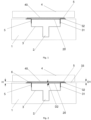
Fig. 1 is a schematic view of a bonding jig according to an exemplary embodiment. -
Fig. 2 is a schematic view of a bonding jig according to an exemplary embodiment. -
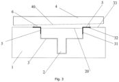
Fig. 3 is a schematic view of another bonding jig according to an exemplary embodiment. - As shown in
Fig. 1 , the bonding jig includes ajig body 1 defining apositioning chamber 3 which has an opening and is configured to position a firstadhesive surface 20 of afirst object 2, the firstadhesive surface 20 being a surface of thefirst object 2 to be adhered to a secondadhesive surface 40 of asecond object 4, in which ananti-sticking layer 5 is provided on each of anupper surface 32 of a periphery of the opening, the upper surface facing the secondadhesive surface 40, and an innercircumferential wall surface 31 of the opening. - Occasionally, the anti-sticking layer can be provided as an anti-sticking coating layer or an anti-sticking plating layer, in which a gap of 0.5mm may be reduced to 0.2mm, 0.15mm or 0.1mm. If there is no anti-sticking coating layer, the gap needs to be wide enough to prevent the jig from being bonded with the adhesive; but if the gap is too wide, the adhesive will spill and become irregular. If the jig is provided with the anti-sticking coating layer, the gap may be very small, such that the jig can position and limit the adhesive to make the spilled adhesive well-distributed. If the spilled adhesive needs to surround a bonded object evenly, the jig can be employed in this manner. Referring to
Fig. 2 , the working principle of the bonding jig is presented as follows. - The
first object 2 is placed in thepositioning chamber 3 whose spatial shape corresponds to the one of thefirst object 2, so as to retain the position of thefirst object 2 to fix the position of the firstadhesive surface 20 of thefirst object 2. - An
adhesive 6 is applied onto the firstadhesive surface 20 of thefirst object 2. - The second
adhesive surface 40 of thesecond object 4 is overlaid onto the firstadhesive surface 20 coated with theadhesive 6. The firstadhesive surface 20 is bonded with the secondadhesive surface 40 by proper pressing, and meanwhile, part of the adhesive will spill onto theupper surface 32 and the innercircumferential wall surface 31. Since theupper surface 32 and the innercircumferential wall surface 31 are provided with the anti-sticking layers, the spilled adhesive will not be bonded with the bonding jig, and it is easy to separate the adhesive from the bonding jig. - Consequently, as for the bonding jig, the anti-sticking layers are arranged at the position where the spilled adhesive is in contact with the bonding jig, to avoid the bonding between the spilled adhesive and the bonding jig, and to facilitate separation of the spilled adhesive from the bonding jig for the users' convenience.
- As shown in
Fig. 2 , theplane 33 in which the opening of thepositioning chamber 3 is located is parallel to the firstadhesive surface 20 and the secondadhesive surface 40, such that the spilled adhesives on both sides are equivalent, and the anti-sticking layers can still avoid the bonding between the spilled adhesive and the bonding jig. Moreover, for some applications, if the firstadhesive surface 20 needs to be bonded with the secondadhesive surface 40 in a nonparallel manner, i.e. theplane 33 in which the opening of thepositioning chamber 3 is located in parallel to the firstadhesive surface 20 and nonparallel to the secondadhesive surface 40, as shown inFig. 3 , the bonding jig can still prevent the spilled adhesive at both sides from bonding with the bonding jig. - Occasionally, a first distance D1 from the
plane 33 in which the opening of thepositioning chamber 3 is located to the secondadhesive surface 40 is equal to or smaller than a predetermined value, and an adhesive 6 between the firstadhesive surface 20 and the secondadhesive surface 40 has a predetermined thickness H. The first distance D1 actually refers to the thickness of the spilled adhesive, i.e. controlling the thickness of the spilled adhesive within the predetermined value, and the predetermined value can be set according to the practical requirements. In practice, the height of the positioning chamber in the bonding jig can be designed based on the predetermined thickness and the height of the first object, such that the thickness of the spilled adhesive is equal to or smaller than the predetermined value to avoid overspill of the adhesive, which may degrade the esthetic effect. - As shown in
Fig. 2 , theplane 33 in which the opening of thepositioning chamber 3 is located is higher than the firstadhesive surface 20 by a second distance D2; the second distance D2 is equal to a difference value between the predetermined thickness H and the first distance D1, such that part of the adhesive is contained within the positioning chamber to control the thickness of the spilled adhesive to be equal to or smaller than the predetermined value for the users' convenience. - Preferably, the predetermined value is equal to or smaller than 0.5mm. For example, the predetermined value is equal to 0.2mm, 0.15mm, 0.1mm, or other values within 0.2mm, so as to guarantee the bonding effect and to reduce the spilled adhesive for aesthetic effect.
Claims (7)
- An assembly comprising a bonding jig, a first object (2), and a second object (4), the bonding jig comprising a jig body (1) defining a positioning chamber (3) which has an opening and is configured to position a first adhesive surface (20) of the first object (2), the first adhesive surface (20) being a surface of the first object (2) to be adhered to a second adhesive surface (40) of the second object (4),
characterized in that an anti-sticking layer (5) is provided on each of an upper surface (32) of a periphery of the opening, the upper surface facing the second adhesive surface (40), and an inner circumferential wall (31) surface of the opening, the first object (2) and the second object (4) are connected via an adhesive (6) between the first adhesive surface (20) and the second adhesive surface (40) , and the anti-sticking layer (5) provided on the upper surface (32) of the periphery of the opening is in contact with the adhesive (6). - The assembly according to claim 1, wherein a plane (33) in which the opening is located is parallel to the first and second adhesive surfaces (20, 40).
- The assembly according to claim 2, wherein a first distance D1 from the plane (33) in which the opening is located to the second adhesive surface (40) is equal to or smaller than a predetermined value, and the adhesive (6) between the first adhesive surface (20) and the second adhesive surface (40) has a predetermined thickness.
- The assembly according to claim 3, wherein the plane (33) in which the opening is located is higher than the first adhesive surface (20) by a second distance; the second distance is equal to a difference value between the predetermined thickness and the first distance.
- The assembly according to claim 3 or 4, wherein the predetermined value is equal to or smaller than 0.5mm.
- The assembly according to claim 5, wherein the predetermined value is equal to 0.2mm, 0.15mm or 0.1mm.
- The assembly according to claim 1, wherein the anti-sticking layer comprises an anti-sticking coating layer or an anti-sticking plating layer.
Applications Claiming Priority (1)
| Application Number | Priority Date | Filing Date | Title |
|---|---|---|---|
| CN201410832172.5A CN104525445A (en) | 2014-12-26 | 2014-12-26 | Adhesive dispensing tool |
Publications (2)
| Publication Number | Publication Date |
|---|---|
| EP3037211A1 EP3037211A1 (en) | 2016-06-29 |
| EP3037211B1 true EP3037211B1 (en) | 2024-02-07 |
Family
ID=52841177
Family Applications (1)
| Application Number | Title | Priority Date | Filing Date |
|---|---|---|---|
| EP15202351.1A Active EP3037211B1 (en) | 2014-12-26 | 2015-12-23 | Bonding jig |
Country Status (9)
| Country | Link |
|---|---|
| US (1) | US9662870B2 (en) |
| EP (1) | EP3037211B1 (en) |
| JP (1) | JP2017507022A (en) |
| KR (1) | KR101727057B1 (en) |
| CN (1) | CN104525445A (en) |
| BR (1) | BR112015017139A2 (en) |
| MX (1) | MX358896B (en) |
| RU (1) | RU2630804C2 (en) |
| WO (1) | WO2016101483A1 (en) |
Families Citing this family (6)
| Publication number | Priority date | Publication date | Assignee | Title |
|---|---|---|---|---|
| CN104525445A (en) | 2014-12-26 | 2015-04-22 | 小米科技有限责任公司 | Adhesive dispensing tool |
| CN110016768A (en) * | 2019-04-22 | 2019-07-16 | 厦门华联电子股份有限公司 | A kind of dispensing tooling |
| CN113399206B (en) * | 2021-06-29 | 2023-11-17 | 深圳市优景观复光电有限公司 | SMT patch furnace dispensing process and dispensing equipment |
| CN114857146B (en) * | 2022-04-14 | 2023-09-12 | 日善电脑配件(嘉善)有限公司 | Press fit equipment with good flatness of press fit finished product |
| JP7774526B2 (en) * | 2022-08-25 | 2025-11-21 | 株式会社日立製作所 | Passenger conveyor repair method and moving handrail repair tool |
| CN115846150A (en) * | 2022-11-08 | 2023-03-28 | 江苏珂亦新能源科技有限公司 | Positioning tool for gluing lower tray of battery box and welding process of positioning tool |
Citations (2)
| Publication number | Priority date | Publication date | Assignee | Title |
|---|---|---|---|---|
| US5213747A (en) * | 1991-08-27 | 1993-05-25 | William Lippert | Methods of making fiber-reinforced resin molds |
| US20040207121A1 (en) * | 2003-04-18 | 2004-10-21 | Schiller Paul R. | Process and apparatus for forming stress-free thermosetting resin products in one mold |
Family Cites Families (19)
| Publication number | Priority date | Publication date | Assignee | Title |
|---|---|---|---|---|
| FR2268654A1 (en) * | 1974-04-24 | 1975-11-21 | Delplanque Stephane | Lettering and numbering stencil - has cuttable sheet with adhesive coatings protected by skins |
| JP3457056B2 (en) * | 1994-04-21 | 2003-10-14 | 東洋ゴム工業株式会社 | Method of bonding rubber and metal and rubber body |
| US5715099A (en) * | 1994-04-28 | 1998-02-03 | Ricoh Company, Ltd. | Mounting method and structure for a solid-state image pickup element in an image reading-out apparatus |
| US5443703A (en) * | 1994-08-02 | 1995-08-22 | Tantec, Inc. | Method and apparatus for simultaneous electrical discharge treatment of and adhesive application to a polymer component |
| US20020134489A1 (en) * | 1998-05-11 | 2002-09-26 | Sweeney Theodore J. | Self-dispensing fastener for photocuring adhesive |
| US6524433B2 (en) * | 1998-05-11 | 2003-02-25 | Theodore J. Sweeney, Jr. | Self-dispensing fastener for photocuring adhesive |
| US7473096B2 (en) * | 2006-06-21 | 2009-01-06 | 3M Innovative Properties Company | Orthodontic adhesive dispensing assembly |
| EP2135736B1 (en) * | 2007-04-06 | 2013-02-27 | Taisei Plas Co., Ltd. | Copper alloy composite and process for producing the same |
| US7823277B2 (en) * | 2008-01-30 | 2010-11-02 | Gm Global Technology Operations, Inc. | Pre-nesting of the active area on plates to reduce thickness variation |
| US8042591B2 (en) * | 2008-02-25 | 2011-10-25 | United States Gypsum Company | Paper beading apparatus for wallboard corner beads |
| KR200463077Y1 (en) * | 2010-07-08 | 2012-10-18 | (주)화인플라텍 | Jig Device for Partially Painting Portable Mobile Communications Terminal |
| CN202725451U (en) * | 2012-07-17 | 2013-02-13 | 厦门弘汉光电科技有限公司 | Adhesive dispensing jig |
| CN102909156A (en) * | 2012-10-17 | 2013-02-06 | 日月光半导体制造股份有限公司 | Chip dispensing jig structure and dispensing method |
| CN103847216B (en) * | 2012-11-29 | 2016-08-10 | 宸鸿科技(厦门)有限公司 | Joint tool and using method thereof |
| TWI495568B (en) * | 2012-12-20 | 2015-08-11 | Ind Tech Res Inst | Electronic component devices with pre-debonding function and method for peeling thin film on electronic component |
| CN103831213B (en) * | 2014-03-17 | 2016-08-17 | 东莞勤百扬精密塑胶有限公司 | Screen point glue operation tool |
| CN104084363A (en) * | 2014-07-01 | 2014-10-08 | 东莞市万丰纳米材料有限公司 | LED dispensing process |
| CN104525445A (en) * | 2014-12-26 | 2015-04-22 | 小米科技有限责任公司 | Adhesive dispensing tool |
| CN204380944U (en) * | 2014-12-26 | 2015-06-10 | 小米科技有限责任公司 | Glue-dropping tool |
-
2014
- 2014-12-26 CN CN201410832172.5A patent/CN104525445A/en active Pending
-
2015
- 2015-04-30 RU RU2015130477A patent/RU2630804C2/en active
- 2015-04-30 KR KR1020157020117A patent/KR101727057B1/en active Active
- 2015-04-30 MX MX2015008845A patent/MX358896B/en active IP Right Grant
- 2015-04-30 WO PCT/CN2015/078105 patent/WO2016101483A1/en not_active Ceased
- 2015-04-30 JP JP2016565544A patent/JP2017507022A/en active Pending
- 2015-04-30 BR BR112015017139A patent/BR112015017139A2/en not_active Application Discontinuation
- 2015-12-21 US US14/977,081 patent/US9662870B2/en active Active
- 2015-12-23 EP EP15202351.1A patent/EP3037211B1/en active Active
Patent Citations (2)
| Publication number | Priority date | Publication date | Assignee | Title |
|---|---|---|---|---|
| US5213747A (en) * | 1991-08-27 | 1993-05-25 | William Lippert | Methods of making fiber-reinforced resin molds |
| US20040207121A1 (en) * | 2003-04-18 | 2004-10-21 | Schiller Paul R. | Process and apparatus for forming stress-free thermosetting resin products in one mold |
Also Published As
| Publication number | Publication date |
|---|---|
| KR20160094845A (en) | 2016-08-10 |
| BR112015017139A2 (en) | 2017-07-11 |
| MX358896B (en) | 2018-09-06 |
| WO2016101483A1 (en) | 2016-06-30 |
| RU2630804C2 (en) | 2017-09-13 |
| RU2015130477A (en) | 2017-01-27 |
| US9662870B2 (en) | 2017-05-30 |
| US20160207294A1 (en) | 2016-07-21 |
| CN104525445A (en) | 2015-04-22 |
| KR101727057B1 (en) | 2017-04-14 |
| JP2017507022A (en) | 2017-03-16 |
| EP3037211A1 (en) | 2016-06-29 |
| MX2015008845A (en) | 2016-08-18 |
Similar Documents
| Publication | Publication Date | Title |
|---|---|---|
| EP3037211A1 (en) | Bonding jig | |
| CA2644175A1 (en) | Process for pretreating formed article, bonded article and process for producing same, and coated article and process for producing same | |
| WO2008154185A3 (en) | Thin polishing pad with window and molding process | |
| JP2013160994A5 (en) | ||
| PH12020500227A1 (en) | Release film for production of ceramic green sheet | |
| PL2147773T3 (en) | Coated decorative carrier plate (DPL) with bending edge and method of manufacturing the coated mounting plate | |
| WO2016184086A1 (en) | Dwell clamp | |
| US20110293924A1 (en) | Housing structure for electronic device and manufacturing method thereof | |
| MY160971A (en) | Method for bonding components of a sputtering target, a bonded assembly of sputtering target components and the use thereof | |
| EP3781641A4 (en) | Process for preparing a bonding resin | |
| SG10201908699SA (en) | Pattern coated filter and method | |
| JP2017525591A5 (en) | ||
| TW201639711A (en) | Filming method and panel apparatus made thereof | |
| CN106937495A (en) | Metal shell with logo and forming method thereof and electronic installation | |
| EP3889207A4 (en) | Thermosetting resin composition, film adhesive, prepreg, and production method thereof | |
| KR20190019868A (en) | Method for manufacturing OCA with non-rectagular-shaped cross section and apparatus for the same | |
| JP2019072947A5 (en) | ||
| PH12021552261A1 (en) | Combination of mold and release film, release film, mold, and method for producing molded article | |
| WO2020148205A3 (en) | A method of making molded parts having smooth surface and molded parts made thereof | |
| WO2019135180A3 (en) | Polishing sheet and polishing method | |
| US20160096317A1 (en) | Method of making a molded article and molded article | |
| CN204380944U (en) | Glue-dropping tool | |
| CN109790864A (en) | Suction unit | |
| US20140010996A1 (en) | Curing process, decorated article and method for manufacturing decorated article | |
| CN110718474B (en) | Packaging method, release part and manufacturing method thereof |
Legal Events
| Date | Code | Title | Description |
|---|---|---|---|
| PUAI | Public reference made under article 153(3) epc to a published international application that has entered the european phase |
Free format text: ORIGINAL CODE: 0009012 |
|
| AK | Designated contracting states |
Kind code of ref document: A1 Designated state(s): AL AT BE BG CH CY CZ DE DK EE ES FI FR GB GR HR HU IE IS IT LI LT LU LV MC MK MT NL NO PL PT RO RS SE SI SK SM TR |
|
| AX | Request for extension of the european patent |
Extension state: BA ME |
|
| STAA | Information on the status of an ep patent application or granted ep patent |
Free format text: STATUS: REQUEST FOR EXAMINATION WAS MADE |
|
| 17P | Request for examination filed |
Effective date: 20161130 |
|
| RBV | Designated contracting states (corrected) |
Designated state(s): AL AT BE BG CH CY CZ DE DK EE ES FI FR GB GR HR HU IE IS IT LI LT LU LV MC MK MT NL NO PL PT RO RS SE SI SK SM TR |
|
| STAA | Information on the status of an ep patent application or granted ep patent |
Free format text: STATUS: EXAMINATION IS IN PROGRESS |
|
| 17Q | First examination report despatched |
Effective date: 20200529 |
|
| GRAP | Despatch of communication of intention to grant a patent |
Free format text: ORIGINAL CODE: EPIDOSNIGR1 |
|
| STAA | Information on the status of an ep patent application or granted ep patent |
Free format text: STATUS: GRANT OF PATENT IS INTENDED |
|
| INTG | Intention to grant announced |
Effective date: 20230810 |
|
| P01 | Opt-out of the competence of the unified patent court (upc) registered |
Effective date: 20230925 |
|
| GRAS | Grant fee paid |
Free format text: ORIGINAL CODE: EPIDOSNIGR3 |
|
| GRAA | (expected) grant |
Free format text: ORIGINAL CODE: 0009210 |
|
| STAA | Information on the status of an ep patent application or granted ep patent |
Free format text: STATUS: THE PATENT HAS BEEN GRANTED |
|
| AK | Designated contracting states |
Kind code of ref document: B1 Designated state(s): AL AT BE BG CH CY CZ DE DK EE ES FI FR GB GR HR HU IE IS IT LI LT LU LV MC MK MT NL NO PL PT RO RS SE SI SK SM TR |
|
| REG | Reference to a national code |
Ref country code: GB Ref legal event code: FG4D |
|
| REG | Reference to a national code |
Ref country code: CH Ref legal event code: EP |
|
| REG | Reference to a national code |
Ref country code: IE Ref legal event code: FG4D |
|
| REG | Reference to a national code |
Ref country code: DE Ref legal event code: R096 Ref document number: 602015087467 Country of ref document: DE |
|
| REG | Reference to a national code |
Ref country code: LT Ref legal event code: MG9D |
|
| REG | Reference to a national code |
Ref country code: NL Ref legal event code: MP Effective date: 20240207 |
|
| PG25 | Lapsed in a contracting state [announced via postgrant information from national office to epo] |
Ref country code: IS Free format text: LAPSE BECAUSE OF FAILURE TO SUBMIT A TRANSLATION OF THE DESCRIPTION OR TO PAY THE FEE WITHIN THE PRESCRIBED TIME-LIMIT Effective date: 20240607 |
|
| PG25 | Lapsed in a contracting state [announced via postgrant information from national office to epo] |
Ref country code: LT Free format text: LAPSE BECAUSE OF FAILURE TO SUBMIT A TRANSLATION OF THE DESCRIPTION OR TO PAY THE FEE WITHIN THE PRESCRIBED TIME-LIMIT Effective date: 20240207 |
|
| PG25 | Lapsed in a contracting state [announced via postgrant information from national office to epo] |
Ref country code: GR Free format text: LAPSE BECAUSE OF FAILURE TO SUBMIT A TRANSLATION OF THE DESCRIPTION OR TO PAY THE FEE WITHIN THE PRESCRIBED TIME-LIMIT Effective date: 20240508 |
|
| REG | Reference to a national code |
Ref country code: AT Ref legal event code: MK05 Ref document number: 1655075 Country of ref document: AT Kind code of ref document: T Effective date: 20240207 |
|
| PG25 | Lapsed in a contracting state [announced via postgrant information from national office to epo] |
Ref country code: HR Free format text: LAPSE BECAUSE OF FAILURE TO SUBMIT A TRANSLATION OF THE DESCRIPTION OR TO PAY THE FEE WITHIN THE PRESCRIBED TIME-LIMIT Effective date: 20240207 Ref country code: RS Free format text: LAPSE BECAUSE OF FAILURE TO SUBMIT A TRANSLATION OF THE DESCRIPTION OR TO PAY THE FEE WITHIN THE PRESCRIBED TIME-LIMIT Effective date: 20240507 Ref country code: NL Free format text: LAPSE BECAUSE OF FAILURE TO SUBMIT A TRANSLATION OF THE DESCRIPTION OR TO PAY THE FEE WITHIN THE PRESCRIBED TIME-LIMIT Effective date: 20240207 |
|
| PG25 | Lapsed in a contracting state [announced via postgrant information from national office to epo] |
Ref country code: ES Free format text: LAPSE BECAUSE OF FAILURE TO SUBMIT A TRANSLATION OF THE DESCRIPTION OR TO PAY THE FEE WITHIN THE PRESCRIBED TIME-LIMIT Effective date: 20240207 |
|
| PG25 | Lapsed in a contracting state [announced via postgrant information from national office to epo] |
Ref country code: AT Free format text: LAPSE BECAUSE OF FAILURE TO SUBMIT A TRANSLATION OF THE DESCRIPTION OR TO PAY THE FEE WITHIN THE PRESCRIBED TIME-LIMIT Effective date: 20240207 |
|
| PG25 | Lapsed in a contracting state [announced via postgrant information from national office to epo] |
Ref country code: RS Free format text: LAPSE BECAUSE OF FAILURE TO SUBMIT A TRANSLATION OF THE DESCRIPTION OR TO PAY THE FEE WITHIN THE PRESCRIBED TIME-LIMIT Effective date: 20240507 Ref country code: NO Free format text: LAPSE BECAUSE OF FAILURE TO SUBMIT A TRANSLATION OF THE DESCRIPTION OR TO PAY THE FEE WITHIN THE PRESCRIBED TIME-LIMIT Effective date: 20240507 Ref country code: NL Free format text: LAPSE BECAUSE OF FAILURE TO SUBMIT A TRANSLATION OF THE DESCRIPTION OR TO PAY THE FEE WITHIN THE PRESCRIBED TIME-LIMIT Effective date: 20240207 Ref country code: LT Free format text: LAPSE BECAUSE OF FAILURE TO SUBMIT A TRANSLATION OF THE DESCRIPTION OR TO PAY THE FEE WITHIN THE PRESCRIBED TIME-LIMIT Effective date: 20240207 Ref country code: IS Free format text: LAPSE BECAUSE OF FAILURE TO SUBMIT A TRANSLATION OF THE DESCRIPTION OR TO PAY THE FEE WITHIN THE PRESCRIBED TIME-LIMIT Effective date: 20240607 Ref country code: HR Free format text: LAPSE BECAUSE OF FAILURE TO SUBMIT A TRANSLATION OF THE DESCRIPTION OR TO PAY THE FEE WITHIN THE PRESCRIBED TIME-LIMIT Effective date: 20240207 Ref country code: GR Free format text: LAPSE BECAUSE OF FAILURE TO SUBMIT A TRANSLATION OF THE DESCRIPTION OR TO PAY THE FEE WITHIN THE PRESCRIBED TIME-LIMIT Effective date: 20240508 Ref country code: FI Free format text: LAPSE BECAUSE OF FAILURE TO SUBMIT A TRANSLATION OF THE DESCRIPTION OR TO PAY THE FEE WITHIN THE PRESCRIBED TIME-LIMIT Effective date: 20240207 Ref country code: ES Free format text: LAPSE BECAUSE OF FAILURE TO SUBMIT A TRANSLATION OF THE DESCRIPTION OR TO PAY THE FEE WITHIN THE PRESCRIBED TIME-LIMIT Effective date: 20240207 Ref country code: BG Free format text: LAPSE BECAUSE OF FAILURE TO SUBMIT A TRANSLATION OF THE DESCRIPTION OR TO PAY THE FEE WITHIN THE PRESCRIBED TIME-LIMIT Effective date: 20240207 Ref country code: AT Free format text: LAPSE BECAUSE OF FAILURE TO SUBMIT A TRANSLATION OF THE DESCRIPTION OR TO PAY THE FEE WITHIN THE PRESCRIBED TIME-LIMIT Effective date: 20240207 |
|
| PG25 | Lapsed in a contracting state [announced via postgrant information from national office to epo] |
Ref country code: PT Free format text: LAPSE BECAUSE OF FAILURE TO SUBMIT A TRANSLATION OF THE DESCRIPTION OR TO PAY THE FEE WITHIN THE PRESCRIBED TIME-LIMIT Effective date: 20240607 Ref country code: PL Free format text: LAPSE BECAUSE OF FAILURE TO SUBMIT A TRANSLATION OF THE DESCRIPTION OR TO PAY THE FEE WITHIN THE PRESCRIBED TIME-LIMIT Effective date: 20240207 |
|
| PG25 | Lapsed in a contracting state [announced via postgrant information from national office to epo] |
Ref country code: SE Free format text: LAPSE BECAUSE OF FAILURE TO SUBMIT A TRANSLATION OF THE DESCRIPTION OR TO PAY THE FEE WITHIN THE PRESCRIBED TIME-LIMIT Effective date: 20240207 Ref country code: PT Free format text: LAPSE BECAUSE OF FAILURE TO SUBMIT A TRANSLATION OF THE DESCRIPTION OR TO PAY THE FEE WITHIN THE PRESCRIBED TIME-LIMIT Effective date: 20240607 Ref country code: PL Free format text: LAPSE BECAUSE OF FAILURE TO SUBMIT A TRANSLATION OF THE DESCRIPTION OR TO PAY THE FEE WITHIN THE PRESCRIBED TIME-LIMIT Effective date: 20240207 Ref country code: LV Free format text: LAPSE BECAUSE OF FAILURE TO SUBMIT A TRANSLATION OF THE DESCRIPTION OR TO PAY THE FEE WITHIN THE PRESCRIBED TIME-LIMIT Effective date: 20240207 |
|
| PG25 | Lapsed in a contracting state [announced via postgrant information from national office to epo] |
Ref country code: DK Free format text: LAPSE BECAUSE OF FAILURE TO SUBMIT A TRANSLATION OF THE DESCRIPTION OR TO PAY THE FEE WITHIN THE PRESCRIBED TIME-LIMIT Effective date: 20240207 |
|
| PG25 | Lapsed in a contracting state [announced via postgrant information from national office to epo] |
Ref country code: SM Free format text: LAPSE BECAUSE OF FAILURE TO SUBMIT A TRANSLATION OF THE DESCRIPTION OR TO PAY THE FEE WITHIN THE PRESCRIBED TIME-LIMIT Effective date: 20240207 |
|
| PG25 | Lapsed in a contracting state [announced via postgrant information from national office to epo] |
Ref country code: CZ Free format text: LAPSE BECAUSE OF FAILURE TO SUBMIT A TRANSLATION OF THE DESCRIPTION OR TO PAY THE FEE WITHIN THE PRESCRIBED TIME-LIMIT Effective date: 20240207 Ref country code: EE Free format text: LAPSE BECAUSE OF FAILURE TO SUBMIT A TRANSLATION OF THE DESCRIPTION OR TO PAY THE FEE WITHIN THE PRESCRIBED TIME-LIMIT Effective date: 20240207 |
|
| PG25 | Lapsed in a contracting state [announced via postgrant information from national office to epo] |
Ref country code: SK Free format text: LAPSE BECAUSE OF FAILURE TO SUBMIT A TRANSLATION OF THE DESCRIPTION OR TO PAY THE FEE WITHIN THE PRESCRIBED TIME-LIMIT Effective date: 20240207 |
|
| PG25 | Lapsed in a contracting state [announced via postgrant information from national office to epo] |
Ref country code: SM Free format text: LAPSE BECAUSE OF FAILURE TO SUBMIT A TRANSLATION OF THE DESCRIPTION OR TO PAY THE FEE WITHIN THE PRESCRIBED TIME-LIMIT Effective date: 20240207 Ref country code: SK Free format text: LAPSE BECAUSE OF FAILURE TO SUBMIT A TRANSLATION OF THE DESCRIPTION OR TO PAY THE FEE WITHIN THE PRESCRIBED TIME-LIMIT Effective date: 20240207 Ref country code: RO Free format text: LAPSE BECAUSE OF FAILURE TO SUBMIT A TRANSLATION OF THE DESCRIPTION OR TO PAY THE FEE WITHIN THE PRESCRIBED TIME-LIMIT Effective date: 20240207 Ref country code: EE Free format text: LAPSE BECAUSE OF FAILURE TO SUBMIT A TRANSLATION OF THE DESCRIPTION OR TO PAY THE FEE WITHIN THE PRESCRIBED TIME-LIMIT Effective date: 20240207 Ref country code: DK Free format text: LAPSE BECAUSE OF FAILURE TO SUBMIT A TRANSLATION OF THE DESCRIPTION OR TO PAY THE FEE WITHIN THE PRESCRIBED TIME-LIMIT Effective date: 20240207 Ref country code: CZ Free format text: LAPSE BECAUSE OF FAILURE TO SUBMIT A TRANSLATION OF THE DESCRIPTION OR TO PAY THE FEE WITHIN THE PRESCRIBED TIME-LIMIT Effective date: 20240207 |
|
| REG | Reference to a national code |
Ref country code: DE Ref legal event code: R097 Ref document number: 602015087467 Country of ref document: DE |
|
| PG25 | Lapsed in a contracting state [announced via postgrant information from national office to epo] |
Ref country code: IT Free format text: LAPSE BECAUSE OF FAILURE TO SUBMIT A TRANSLATION OF THE DESCRIPTION OR TO PAY THE FEE WITHIN THE PRESCRIBED TIME-LIMIT Effective date: 20240207 |
|
| PLBE | No opposition filed within time limit |
Free format text: ORIGINAL CODE: 0009261 |
|
| STAA | Information on the status of an ep patent application or granted ep patent |
Free format text: STATUS: NO OPPOSITION FILED WITHIN TIME LIMIT |
|
| PG25 | Lapsed in a contracting state [announced via postgrant information from national office to epo] |
Ref country code: IT Free format text: LAPSE BECAUSE OF FAILURE TO SUBMIT A TRANSLATION OF THE DESCRIPTION OR TO PAY THE FEE WITHIN THE PRESCRIBED TIME-LIMIT Effective date: 20240207 |
|
| 26N | No opposition filed |
Effective date: 20241108 |
|
| PG25 | Lapsed in a contracting state [announced via postgrant information from national office to epo] |
Ref country code: SI Free format text: LAPSE BECAUSE OF FAILURE TO SUBMIT A TRANSLATION OF THE DESCRIPTION OR TO PAY THE FEE WITHIN THE PRESCRIBED TIME-LIMIT Effective date: 20240207 |
|
| REG | Reference to a national code |
Ref country code: DE Ref legal event code: R119 Ref document number: 602015087467 Country of ref document: DE |
|
| PG25 | Lapsed in a contracting state [announced via postgrant information from national office to epo] |
Ref country code: MC Free format text: LAPSE BECAUSE OF FAILURE TO SUBMIT A TRANSLATION OF THE DESCRIPTION OR TO PAY THE FEE WITHIN THE PRESCRIBED TIME-LIMIT Effective date: 20240207 |
|
| REG | Reference to a national code |
Ref country code: CH Ref legal event code: PL |
|
| PG25 | Lapsed in a contracting state [announced via postgrant information from national office to epo] |
Ref country code: LU Free format text: LAPSE BECAUSE OF NON-PAYMENT OF DUE FEES Effective date: 20241223 |
|
| GBPC | Gb: european patent ceased through non-payment of renewal fee |
Effective date: 20241223 |
|
| REG | Reference to a national code |
Ref country code: BE Ref legal event code: MM Effective date: 20241231 |
|
| PG25 | Lapsed in a contracting state [announced via postgrant information from national office to epo] |
Ref country code: DE Free format text: LAPSE BECAUSE OF NON-PAYMENT OF DUE FEES Effective date: 20250701 |
|
| PG25 | Lapsed in a contracting state [announced via postgrant information from national office to epo] |
Ref country code: BE Free format text: LAPSE BECAUSE OF NON-PAYMENT OF DUE FEES Effective date: 20241231 Ref country code: GB Free format text: LAPSE BECAUSE OF NON-PAYMENT OF DUE FEES Effective date: 20241223 |
|
| PG25 | Lapsed in a contracting state [announced via postgrant information from national office to epo] |
Ref country code: FR Free format text: LAPSE BECAUSE OF NON-PAYMENT OF DUE FEES Effective date: 20241231 |
|
| PG25 | Lapsed in a contracting state [announced via postgrant information from national office to epo] |
Ref country code: CH Free format text: LAPSE BECAUSE OF NON-PAYMENT OF DUE FEES Effective date: 20241231 |
|
| PG25 | Lapsed in a contracting state [announced via postgrant information from national office to epo] |
Ref country code: IE Free format text: LAPSE BECAUSE OF NON-PAYMENT OF DUE FEES Effective date: 20241223 |
|
| PG25 | Lapsed in a contracting state [announced via postgrant information from national office to epo] |
Ref country code: CY Free format text: LAPSE BECAUSE OF FAILURE TO SUBMIT A TRANSLATION OF THE DESCRIPTION OR TO PAY THE FEE WITHIN THE PRESCRIBED TIME-LIMIT Effective date: 20240207 |