EP3036747B1 - Erdungsleiter-stromversorgungssystem und verwendung des erdungsleiters - Google Patents
Erdungsleiter-stromversorgungssystem und verwendung des erdungsleiters Download PDFInfo
- Publication number
- EP3036747B1 EP3036747B1 EP15839134.2A EP15839134A EP3036747B1 EP 3036747 B1 EP3036747 B1 EP 3036747B1 EP 15839134 A EP15839134 A EP 15839134A EP 3036747 B1 EP3036747 B1 EP 3036747B1
- Authority
- EP
- European Patent Office
- Prior art keywords
- grounding conductor
- grounding
- aluminium
- strand
- sheath
- Prior art date
- Legal status (The legal status is an assumption and is not a legal conclusion. Google has not performed a legal analysis and makes no representation as to the accuracy of the status listed.)
- Active
Links
- 239000004020 conductor Substances 0.000 title claims description 244
- 239000004411 aluminium Substances 0.000 claims description 141
- 229910052782 aluminium Inorganic materials 0.000 claims description 141
- XAGFODPZIPBFFR-UHFFFAOYSA-N aluminium Chemical compound [Al] XAGFODPZIPBFFR-UHFFFAOYSA-N 0.000 claims description 141
- 229920001940 conductive polymer Polymers 0.000 claims description 70
- 239000002861 polymer material Substances 0.000 claims description 52
- 239000006229 carbon black Substances 0.000 claims description 23
- -1 polypropylene Polymers 0.000 claims description 17
- 229920001971 elastomer Polymers 0.000 claims description 15
- 239000000806 elastomer Substances 0.000 claims description 13
- HQQADJVZYDDRJT-UHFFFAOYSA-N ethene;prop-1-ene Chemical group C=C.CC=C HQQADJVZYDDRJT-UHFFFAOYSA-N 0.000 claims description 13
- 239000004743 Polypropylene Substances 0.000 claims description 10
- 239000002530 phenolic antioxidant Substances 0.000 claims description 10
- 229920001155 polypropylene Polymers 0.000 claims description 10
- 239000003963 antioxidant agent Substances 0.000 claims description 4
- 239000003575 carbonaceous material Substances 0.000 claims description 4
- 229920000098 polyolefin Polymers 0.000 claims description 4
- 230000003078 antioxidant effect Effects 0.000 claims description 3
- 238000012360 testing method Methods 0.000 description 92
- 230000007797 corrosion Effects 0.000 description 57
- 238000005260 corrosion Methods 0.000 description 57
- PNEYBMLMFCGWSK-UHFFFAOYSA-N Alumina Chemical compound [O-2].[O-2].[O-2].[Al+3].[Al+3] PNEYBMLMFCGWSK-UHFFFAOYSA-N 0.000 description 45
- 239000000463 material Substances 0.000 description 37
- 229920000642 polymer Polymers 0.000 description 35
- RYGMFSIKBFXOCR-UHFFFAOYSA-N Copper Chemical compound [Cu] RYGMFSIKBFXOCR-UHFFFAOYSA-N 0.000 description 29
- 229910052802 copper Inorganic materials 0.000 description 29
- 239000010949 copper Substances 0.000 description 29
- 239000010410 layer Substances 0.000 description 28
- 239000002689 soil Substances 0.000 description 19
- 229910052751 metal Inorganic materials 0.000 description 17
- 239000002184 metal Substances 0.000 description 17
- 230000000694 effects Effects 0.000 description 16
- 238000010998 test method Methods 0.000 description 15
- 239000011148 porous material Substances 0.000 description 14
- 230000006378 damage Effects 0.000 description 12
- 238000001125 extrusion Methods 0.000 description 10
- 239000000243 solution Substances 0.000 description 10
- 150000001875 compounds Chemical class 0.000 description 9
- 239000011159 matrix material Substances 0.000 description 9
- 239000000945 filler Substances 0.000 description 8
- 230000001681 protective effect Effects 0.000 description 8
- XLYOFNOQVPJJNP-UHFFFAOYSA-N water Substances O XLYOFNOQVPJJNP-UHFFFAOYSA-N 0.000 description 8
- 239000004698 Polyethylene Substances 0.000 description 7
- 238000005299 abrasion Methods 0.000 description 7
- 229910052593 corundum Inorganic materials 0.000 description 7
- 238000004519 manufacturing process Methods 0.000 description 7
- 229920000573 polyethylene Polymers 0.000 description 7
- 229910001845 yogo sapphire Inorganic materials 0.000 description 7
- XEEYBQQBJWHFJM-UHFFFAOYSA-N Iron Chemical compound [Fe] XEEYBQQBJWHFJM-UHFFFAOYSA-N 0.000 description 6
- PMZURENOXWZQFD-UHFFFAOYSA-L Sodium Sulfate Chemical compound [Na+].[Na+].[O-]S([O-])(=O)=O PMZURENOXWZQFD-UHFFFAOYSA-L 0.000 description 6
- 238000010586 diagram Methods 0.000 description 6
- 239000007788 liquid Substances 0.000 description 6
- 238000000034 method Methods 0.000 description 6
- OKTJSMMVPCPJKN-UHFFFAOYSA-N Carbon Chemical compound [C] OKTJSMMVPCPJKN-UHFFFAOYSA-N 0.000 description 4
- 239000000654 additive Substances 0.000 description 4
- 239000002322 conducting polymer Substances 0.000 description 4
- 230000002633 protecting effect Effects 0.000 description 4
- 230000002829 reductive effect Effects 0.000 description 4
- 229910000831 Steel Inorganic materials 0.000 description 3
- QAOWNCQODCNURD-UHFFFAOYSA-L Sulfate Chemical compound [O-]S([O-])(=O)=O QAOWNCQODCNURD-UHFFFAOYSA-L 0.000 description 3
- 230000000996 additive effect Effects 0.000 description 3
- QVGXLLKOCUKJST-UHFFFAOYSA-N atomic oxygen Chemical compound [O] QVGXLLKOCUKJST-UHFFFAOYSA-N 0.000 description 3
- 230000008901 benefit Effects 0.000 description 3
- 239000002131 composite material Substances 0.000 description 3
- 238000009826 distribution Methods 0.000 description 3
- 229910052742 iron Inorganic materials 0.000 description 3
- 238000005259 measurement Methods 0.000 description 3
- 239000000203 mixture Substances 0.000 description 3
- 229910052760 oxygen Inorganic materials 0.000 description 3
- 239000001301 oxygen Substances 0.000 description 3
- 239000002245 particle Substances 0.000 description 3
- 229910052938 sodium sulfate Inorganic materials 0.000 description 3
- 235000011152 sodium sulphate Nutrition 0.000 description 3
- 239000010959 steel Substances 0.000 description 3
- 229910021653 sulphate ion Inorganic materials 0.000 description 3
- KAKZBPTYRLMSJV-UHFFFAOYSA-N Butadiene Chemical compound C=CC=C KAKZBPTYRLMSJV-UHFFFAOYSA-N 0.000 description 2
- 239000005062 Polybutadiene Substances 0.000 description 2
- 230000009286 beneficial effect Effects 0.000 description 2
- 230000008859 change Effects 0.000 description 2
- 239000011231 conductive filler Substances 0.000 description 2
- 230000005684 electric field Effects 0.000 description 2
- 230000007613 environmental effect Effects 0.000 description 2
- 230000001747 exhibiting effect Effects 0.000 description 2
- 239000003864 humus Substances 0.000 description 2
- 229920001684 low density polyethylene Polymers 0.000 description 2
- 239000004702 low-density polyethylene Substances 0.000 description 2
- 238000002844 melting Methods 0.000 description 2
- 230000008018 melting Effects 0.000 description 2
- 239000011241 protective layer Substances 0.000 description 2
- 230000000630 rising effect Effects 0.000 description 2
- 239000005060 rubber Substances 0.000 description 2
- 229920003048 styrene butadiene rubber Polymers 0.000 description 2
- 229910000838 Al alloy Inorganic materials 0.000 description 1
- 229920002943 EPDM rubber Polymers 0.000 description 1
- 244000043261 Hevea brasiliensis Species 0.000 description 1
- FYYHWMGAXLPEAU-UHFFFAOYSA-N Magnesium Chemical compound [Mg] FYYHWMGAXLPEAU-UHFFFAOYSA-N 0.000 description 1
- 239000002174 Styrene-butadiene Substances 0.000 description 1
- ATJFFYVFTNAWJD-UHFFFAOYSA-N Tin Chemical compound [Sn] ATJFFYVFTNAWJD-UHFFFAOYSA-N 0.000 description 1
- 239000006230 acetylene black Substances 0.000 description 1
- 230000009471 action Effects 0.000 description 1
- 238000004026 adhesive bonding Methods 0.000 description 1
- 229910045601 alloy Inorganic materials 0.000 description 1
- 239000000956 alloy Substances 0.000 description 1
- 229910021502 aluminium hydroxide Inorganic materials 0.000 description 1
- WNROFYMDJYEPJX-UHFFFAOYSA-K aluminium hydroxide Chemical compound [OH-].[OH-].[OH-].[Al+3] WNROFYMDJYEPJX-UHFFFAOYSA-K 0.000 description 1
- 238000002048 anodisation reaction Methods 0.000 description 1
- 230000004888 barrier function Effects 0.000 description 1
- 229920005601 base polymer Polymers 0.000 description 1
- 229910001680 bayerite Inorganic materials 0.000 description 1
- 239000011230 binding agent Substances 0.000 description 1
- 238000009933 burial Methods 0.000 description 1
- 229910052799 carbon Inorganic materials 0.000 description 1
- 239000004568 cement Substances 0.000 description 1
- 239000000805 composite resin Substances 0.000 description 1
- 230000001010 compromised effect Effects 0.000 description 1
- 238000010276 construction Methods 0.000 description 1
- 239000012611 container material Substances 0.000 description 1
- 229920001577 copolymer Polymers 0.000 description 1
- 230000003247 decreasing effect Effects 0.000 description 1
- 230000006866 deterioration Effects 0.000 description 1
- 239000008151 electrolyte solution Substances 0.000 description 1
- 239000003063 flame retardant Substances 0.000 description 1
- 239000011888 foil Substances 0.000 description 1
- 230000006870 function Effects 0.000 description 1
- 239000006232 furnace black Substances 0.000 description 1
- 229910001679 gibbsite Inorganic materials 0.000 description 1
- 239000008187 granular material Substances 0.000 description 1
- 239000010439 graphite Substances 0.000 description 1
- 229910002804 graphite Inorganic materials 0.000 description 1
- 238000010438 heat treatment Methods 0.000 description 1
- 238000013095 identification testing Methods 0.000 description 1
- 239000012535 impurity Substances 0.000 description 1
- 239000003112 inhibitor Substances 0.000 description 1
- 230000005764 inhibitory process Effects 0.000 description 1
- 238000013101 initial test Methods 0.000 description 1
- 231100000518 lethal Toxicity 0.000 description 1
- 230000001665 lethal effect Effects 0.000 description 1
- 229910052749 magnesium Inorganic materials 0.000 description 1
- 239000011777 magnesium Substances 0.000 description 1
- 230000007257 malfunction Effects 0.000 description 1
- 239000007769 metal material Substances 0.000 description 1
- 150000002739 metals Chemical class 0.000 description 1
- VNWKTOKETHGBQD-UHFFFAOYSA-N methane Chemical compound C VNWKTOKETHGBQD-UHFFFAOYSA-N 0.000 description 1
- 229920003052 natural elastomer Polymers 0.000 description 1
- 229920001194 natural rubber Polymers 0.000 description 1
- 150000002825 nitriles Chemical class 0.000 description 1
- 230000003647 oxidation Effects 0.000 description 1
- 238000007254 oxidation reaction Methods 0.000 description 1
- 230000036961 partial effect Effects 0.000 description 1
- 238000011056 performance test Methods 0.000 description 1
- 229920002857 polybutadiene Polymers 0.000 description 1
- 230000008569 process Effects 0.000 description 1
- 238000012545 processing Methods 0.000 description 1
- 230000009993 protective function Effects 0.000 description 1
- 239000011347 resin Substances 0.000 description 1
- 229920005989 resin Polymers 0.000 description 1
- 150000003839 salts Chemical class 0.000 description 1
- 229920006395 saturated elastomer Polymers 0.000 description 1
- 239000007787 solid Substances 0.000 description 1
- 229920001897 terpolymer Polymers 0.000 description 1
- 239000012085 test solution Substances 0.000 description 1
- 230000007704 transition Effects 0.000 description 1
Images


Classifications
-
- H—ELECTRICITY
- H01—ELECTRIC ELEMENTS
- H01B—CABLES; CONDUCTORS; INSULATORS; SELECTION OF MATERIALS FOR THEIR CONDUCTIVE, INSULATING OR DIELECTRIC PROPERTIES
- H01B1/00—Conductors or conductive bodies characterised by the conductive materials; Selection of materials as conductors
- H01B1/02—Conductors or conductive bodies characterised by the conductive materials; Selection of materials as conductors mainly consisting of metals or alloys
- H01B1/023—Alloys based on aluminium
-
- C—CHEMISTRY; METALLURGY
- C08—ORGANIC MACROMOLECULAR COMPOUNDS; THEIR PREPARATION OR CHEMICAL WORKING-UP; COMPOSITIONS BASED THEREON
- C08L—COMPOSITIONS OF MACROMOLECULAR COMPOUNDS
- C08L23/00—Compositions of homopolymers or copolymers of unsaturated aliphatic hydrocarbons having only one carbon-to-carbon double bond; Compositions of derivatives of such polymers
- C08L23/02—Compositions of homopolymers or copolymers of unsaturated aliphatic hydrocarbons having only one carbon-to-carbon double bond; Compositions of derivatives of such polymers not modified by chemical after-treatment
- C08L23/10—Homopolymers or copolymers of propene
- C08L23/12—Polypropene
-
- C—CHEMISTRY; METALLURGY
- C08—ORGANIC MACROMOLECULAR COMPOUNDS; THEIR PREPARATION OR CHEMICAL WORKING-UP; COMPOSITIONS BASED THEREON
- C08L—COMPOSITIONS OF MACROMOLECULAR COMPOUNDS
- C08L23/00—Compositions of homopolymers or copolymers of unsaturated aliphatic hydrocarbons having only one carbon-to-carbon double bond; Compositions of derivatives of such polymers
- C08L23/02—Compositions of homopolymers or copolymers of unsaturated aliphatic hydrocarbons having only one carbon-to-carbon double bond; Compositions of derivatives of such polymers not modified by chemical after-treatment
- C08L23/16—Ethene-propene or ethene-propene-diene copolymers
-
- H—ELECTRICITY
- H01—ELECTRIC ELEMENTS
- H01B—CABLES; CONDUCTORS; INSULATORS; SELECTION OF MATERIALS FOR THEIR CONDUCTIVE, INSULATING OR DIELECTRIC PROPERTIES
- H01B1/00—Conductors or conductive bodies characterised by the conductive materials; Selection of materials as conductors
- H01B1/06—Conductors or conductive bodies characterised by the conductive materials; Selection of materials as conductors mainly consisting of other non-metallic substances
- H01B1/12—Conductors or conductive bodies characterised by the conductive materials; Selection of materials as conductors mainly consisting of other non-metallic substances organic substances
- H01B1/124—Intrinsically conductive polymers
- H01B1/125—Intrinsically conductive polymers comprising aliphatic main chains, e.g. polyactylenes
-
- H—ELECTRICITY
- H01—ELECTRIC ELEMENTS
- H01B—CABLES; CONDUCTORS; INSULATORS; SELECTION OF MATERIALS FOR THEIR CONDUCTIVE, INSULATING OR DIELECTRIC PROPERTIES
- H01B9/00—Power cables
- H01B9/008—Power cables for overhead application
-
- H—ELECTRICITY
- H01—ELECTRIC ELEMENTS
- H01R—ELECTRICALLY-CONDUCTIVE CONNECTIONS; STRUCTURAL ASSOCIATIONS OF A PLURALITY OF MUTUALLY-INSULATED ELECTRICAL CONNECTING ELEMENTS; COUPLING DEVICES; CURRENT COLLECTORS
- H01R4/00—Electrically-conductive connections between two or more conductive members in direct contact, i.e. touching one another; Means for effecting or maintaining such contact; Electrically-conductive connections having two or more spaced connecting locations for conductors and using contact members penetrating insulation
- H01R4/58—Electrically-conductive connections between two or more conductive members in direct contact, i.e. touching one another; Means for effecting or maintaining such contact; Electrically-conductive connections having two or more spaced connecting locations for conductors and using contact members penetrating insulation characterised by the form or material of the contacting members
- H01R4/66—Connections with the terrestrial mass, e.g. earth plate, earth pin
-
- H—ELECTRICITY
- H02—GENERATION; CONVERSION OR DISTRIBUTION OF ELECTRIC POWER
- H02G—INSTALLATION OF ELECTRIC CABLES OR LINES, OR OF COMBINED OPTICAL AND ELECTRIC CABLES OR LINES
- H02G13/00—Installations of lightning conductors; Fastening thereof to supporting structure
- H02G13/40—Connection to earth
-
- C—CHEMISTRY; METALLURGY
- C08—ORGANIC MACROMOLECULAR COMPOUNDS; THEIR PREPARATION OR CHEMICAL WORKING-UP; COMPOSITIONS BASED THEREON
- C08L—COMPOSITIONS OF MACROMOLECULAR COMPOUNDS
- C08L2203/00—Applications
- C08L2203/20—Applications use in electrical or conductive gadgets
- C08L2203/202—Applications use in electrical or conductive gadgets use in electrical wires or wirecoating
-
- C—CHEMISTRY; METALLURGY
- C08—ORGANIC MACROMOLECULAR COMPOUNDS; THEIR PREPARATION OR CHEMICAL WORKING-UP; COMPOSITIONS BASED THEREON
- C08L—COMPOSITIONS OF MACROMOLECULAR COMPOUNDS
- C08L2205/00—Polymer mixtures characterised by other features
- C08L2205/02—Polymer mixtures characterised by other features containing two or more polymers of the same C08L -group
Definitions
- the invention relates to a grounding conductor e.g. in the form of a grounding line, a rod, or a mesh, as well as it relates to an electrical power system comprising such grounding conductor and use of a grounding conductor.
- Grounding conductors are well known in the art, where this term herein means a grounding conductor intended for air and/or ground laid power line distribution network applications, where the grounding conductor is adapted to be laid underground, in water or in air, outside or inside ducts; and where the grounding conductor is provided in connection with or at a distance to an AC or DC power cable, such as an AC single or three phased power cable, or power structure, such as a pole, a transformer station, or a building, which power cable or structure is provided above ground, or provided in direct contact with or alongside said power cable in the ground.
- the purpose of the grounding conductor is to form a ground or earth potential to the power cable or structure.
- grounding conductors are provided following, along, or being integrated with ground laid power cables. In some cases at least part of said grounding conductor is provided following, along, or integrated with aerial power cables.
- the grounding conductor can be applied in the ground near individual poles, on site providing system ground, under transformers, or close by buildings, e.g. by providing a mesh, or can be applied following the power cable and laid underground as a ground conductor.
- Said conductor can be utilized comprising any suitable diameter as to form straight or twisted wires, strands, rods, or pipes.
- grounding conductor is herein defined as a conductor suitable for being in electrical contact with the surrounding environment for providing grounding potential along substantially the entire length of the grounding conductor where laid in the ground.
- grounding conductor does not cover externally electrically insulated and internally electrically conducting conductors which only provide grounding potential at the conductor end or ends with e.g. a cable lug or clamp.
- a bare copper material is conventionally used as a grounding device.
- Bare copper materials serving as grounding devices may be arranged on or in the earth buried at a predetermined depth, and the copper materials being arranged in a grid pattern in a vertical and horizontal directions. This constitutes a mesh electrode.
- a grounding device having such a mesh electrode is disclosed in the Unexamined Japanese Patent Application Publication (Tokkai-Sho) No. 59-211975 .
- the conventional grounding device exhibiting a bare metal surface such as bare copper e.g. constituting a mesh electrode as described above
- said bare metal devices are arranged directly in contact with and inside the soil of the earth. Accordingly, corrosion of the bare metal grounding device is facilitated by moisture in the soil, the acidity of the soil, the concentration of salt in the soil, and the like.
- the buried grounding device can be damaged thereby and may be subjected to a disconnection or the like, thus spoiling the grounding function of the grounding device.
- bare copper grounding devices tend to exhibit a long lifetime due to its good inherent corrosion stability.
- other metals are more easily corroded, such as e.g. aluminium and iron.
- the bare metal is covered with a low resistance material comprising a compound of electrically conducting carbon material and a binder material, often called a cement, thus providing a grounding conductor, a disconnection or the like caused by the corrosion attributed directly to the soil is of course less likely to occur as compared to when the bare metal, such as the aluminium or iron arranged directly in the earth.
- a low resistance material comprising a compound of electrically conducting carbon material and a binder material, often called a cement
- the specific resistance of the soil may change rapidly locally due to environmental or soil conditions, such as lightning strikes or water content, or it may change over the length of the grounding conductor.
- the grounding conductors are not completely covered with low resistance material, e.g. has holes due to e.g. mechanical damages or lightning induced damages, which holes lead to one or more areas of exposed bare metal.
- electromagnetic leaders may form and extend from the ground conductors during such lightning strikes, as the carbon in the covering compound is very unlikely to be ionized.
- grounding conductors In combination with other protective devices such as fuses and residual current devices, is ultimately to protect and ensure that living beings do not come into contact with metallic or leading objects, such as a power line or the ground itself, whose potential relative to the living beings own potential exceeds a "safe" threshold, typically set to around 50 V.
- the rising copper costs and the stolen copper also encourage suppliers and operators of power lines to consider reducing the amount of copper materials being utilized, in particular when installing or re-installing longer lengths of grounding conductor along a power cable.
- aluminium inherently - on contact with oxygen - forms a thin layer of aluminium oxide which generally tend to lower surface corrosion, aluminium does tend to be more reactive with water than copper. Further, aluminium is less electrically conductive, around 40-60% less conductive. Thus, aluminium conductors generally are made with a corresponding larger diameter in order to attain the same resistance as the copper ones.
- EP 0 136 039 dating from 1983 describes a grounding device in the form of a ground rod or mesh mat intended for lightning protection by burial in the ground, where the device comprises a metallic central member, e.g. made of aluminium or preferably steel, and a surrounding electrically conductive polymer member for moisture protection.
- the polymer member has a specific resistance of from 0.01 ⁇ cm to 10 ⁇ cm.
- JP 10-223279 dating from 1996 describes a method of preventing the oxidation of a grounded electrode made from copper, aluminium or steel by using a semi-conductive anticorrosive layer formed on a conductor as the grounded electrode to be electrically connected to electric equipment and embedded in the ground.
- the semi-conductive anticorrosive layer is formed by covering a crosslinked or non-crosslinked semiconductive polyethylene composite with a semi-conductive resin composite containing conductive carbon black by extrusion, and its volume specific resistance is set to 1/20- I1/100 of the specific resistance of the soil embedding the electrode.
- US 3571613 discloses a two-cable underground electrical distribution system for single phase, which has an insulated power conductor with longitudinal bosses in the jacket into which are embedded no more than four undulatory drain wires, and a separate or duplex return conductor.
- the present invention provides a grounding conductor, which utilizes aluminium as a grounding conductor material alternative, and which also addresses at last some of the above mentioned disadvantages with prior art grounding conductors.
- the present invention provides a grounding conductor as disclosed in claim 1 and the use of it is disclosed in claim 11.
- the grounding conductor comprise a plurality of conductive aluminium strands wherein each such strand is provided with at least one sheath comprising an electrically conductive polymer material having a volume resistivity ( ⁇ ) below 100 ⁇ cm.
- the grounding conductor comprises a plurality of conductive aluminium strands wherein each such strand is provided with at least one sheath comprising an electrically conductive polymer material having a volume resistivity ( ⁇ ) below 100 ⁇ cm, a grounding wire comprising aluminium is provided, which fulfils the requirements of a grounding conductor. Moreover, due to the provision of the plurality of sheathed conductive aluminium strands the properties of the grounding conductor are maintained even if some of the sheaths comprising electrically conductive polymer are damaged. As a result, the above mentioned object is achieved.
- a grounding conductor comprising at least one conductive aluminium strand having a strand diameter, dw, along the length thereof, where each such strand is provided with at least one sheath of an electrically conductive polymer material having a sheath thickness, ts, and having a volume resistivity, p, below 100 ⁇ cm.
- the material of said electrically conductive polymer may be such that for at least said one aluminium strand at least one of these criteria is true: Criteria 1) that when comparing a sheathed-strand potential difference and a bare-strand-potential difference, said sheathed-strand potential difference is lower than said bare-strand potential difference at least at one point over a first test current range when testing according to the following first test procedure: - providing a length, Is, of said at least one sheathed aluminium strand;- a1) submerging a portion of said length into a 1 vol% sodium sulphate solution wherein a metal electrode is provided at a distance to said aluminium strand;- b1) applying a test current within said first test current range over said at least one sheathed aluminium strand such that a negative test potential is applied to said aluminium strand relative to said electrode; - c1) acquiring said sheathed-strand potential difference between said at least one sheathed aluminium strand and said electrode;
- Criteria 2 that when comparing a sheathed-strand potential difference and a sheathed-strand-with-hole potential difference, said sheathed-strand-with- hole potential difference is higher than said sheathed-strand-potential difference at least at one point over a second test current range, when testing according to the following second test procedure: - providing a length, Is, of said at least one sheathed aluminium strand;- a2) applying a test current within said second test current range over said at least one sheathed aluminium strand and said electrode such that a potential difference is provided between said at least one sheathed aluminium strand and said electrode; - b2) acquiring said sheathed-strand-potential difference; - c2) repeating said steps a2) to b2) over said second current test range at suitable intervals; - d2) making a hole in the sheath from the same length, Is, of aluminium strand and testing according to the steps a2)-c2), except in b2)
- Meeting at least one of the test criteria 1) or 2) means that the grounding conductor comprising said conductive polymer material is suitable for the application, in that the galvanic corrosion tendency is lowered, as well as the grounding capability is increased, as well as lightning impulse removal effectiveness is improved.
- the contacting surfaces might even provide a potential "well" which the electrons are being led into. This has been tested for low currents as up to 5 mA on aluminium strand in the 1 vol% sodium sulphate solution.
- a conductive polymer sheath material is suitable as a conductive polymer material for aluminium containing grounding conductors, at least what concerns the sheaths corrosive inhibitor properties. It has also been seen that the material then is much better electrically conducting and thus provides a better grounding effect. Such material seems to enable a very low voltage potential drop over it compared to other conductive polymers. Such sheath seems to provide a lower voltage potential bridge which the electrons of the electrical current "needs to" overcome, in fact it seems as if the sheath is even better at conducting the current to ground than the bare aluminium material is.
- the material of said electrically conductive polymer is such that said at least one of said one or more aluminium strands can pass both of said two test procedures.
- An unsuitable polymer will instead generate a high voltage drop between the aluminium stand and the surrounding medium (e.g. soil) of the conductor.
- An unsuitable polymer thus, will render the conductor unsuitable for use as a grounding conductor. Further, an unsuitable polymer may cause corrosion of the aluminium strand.
- the size of such test hole in the sheath for the above discussed test criteria in its longitudinal extension relative to the length Is of the sample may be in the range of less than 10%, such as less than 5%, such as less than 4%, such as less than 2%, such as less than 1% thereof.
- the test hole may be in the form of a slit thus, having no substantial extension in a circumferential direction of the relevant strand.
- a hole may be created in the sheath due to an unintentional damage, e.g. during manufacturing of the grounding conductor, handling of the grounding conductor, or laying of the grounding conductor. Due to the properties of the conductive polymer discussed herein, the grounding properties of the grounding conductor are not particularly affected by such a hole.
- the advantageous grounding effect may have to do with the polymer material providing a good conductive contact with the outer surface of said at least one aluminium strand and onwards towards the generally much more resistive earth potential, when in use. This seems to provide a very low potential wall for the electrons of the electrical current to "overcome", see below for list of parameters which may influence the test results and provide a suitable grounding conductor.
- At least some of the plurality of aluminium strands may be twisted around each other.
- At least some of the plurality of conductive aluminium strands may entirely surround one centrally provided conductive aluminium strand of the plurality of conductive aluminium strands. In this manner the centrally provided conductive aluminium strand may be mechanically protected by the surrounding aluminium strands.
- a transitional resistance for one of the plurality of the conductive aluminium strands provided with at least one sheath to a surrounding media may be lower than a transitional resistance for a bare conductive aluminium strand of the plurality of the conductive aluminium strands to the same surrounding media.
- the conductive polymer material may comprise a polyolefin mixed with an elastomer, 10-40 % high purity carbonaceous material, and an antioxidant. In this manner a sheath having a volume resistivity p below 100 ⁇ cm may be provided in a durable material suited for good conductive contact to the aluminium strand.
- the conductive polymer material may comprise polypropylene mixed with an ethylene/propylene elastomer, 23 - 30 % carbon black, and a phenolic antioxidant polyolefin mixed with an elastomer.
- a sheath having a volume resistivity ⁇ below 40 ⁇ cm may be provided.
- the sheath may have a volume resistivity p within a range of 5 - 40 ⁇ cm.
- Such a conductive material provides a good conductive contact to the aluminium strand.
- the conductive polymer material provides a wear resistance, a hardness, and a toughness which is higher compared to many other conductive polymer materials.
- the grounding conductor is suited to withstand the handling it is subjected to during laying and use as a grounding conductor. Accordingly, the grounding conductor provides a realistic alternative to the hitherto used copper grounding conductors.
- the conductive polymer material may comprise comprises 62 - 68 % polypropylene mixed with an ethylene/propylene elastomer, 23 - 30 % carbon black, and 2 - 4% phenolic antioxidant.
- a sheath having a volume resistivity p below 40 ⁇ cm may be provided.
- the sheath may have a volume resistivity p within a range of 5 - 40 ⁇ cm.
- Such a conductive material provides a good conductive contact to the aluminium strand.
- the conductive material may penetrate into pores of the aluminium strand.
- the conductive polymer material provides a wear resistance, a hardness, and a toughness which is higher compared to many other conductive polymer materials.
- the grounding conductor is suited to withstand the handling it is subjected to during laying and use as a grounding conductor. Accordingly, the grounding conductor provides a realistic alternative to the hitherto used copper grounding conductors.
- the conductive polymer material may comprise 25 - 70 % polypropylene, 15 - 55% ethylene/propylene elastomer, 23 - 30 % carbon black, and 2 - 4 % phenolic antioxidant.
- a sheath having a volume resistivity p below 40 ⁇ cm may be provided.
- the sheath may have a volume resistivity p within a range of 5 - 40 ⁇ cm.
- Such a conductive material provides a good conductive contact to the aluminium strand.
- the conductive material may penetrate into pores of the aluminium strand.
- the conductive polymer material provides a wear resistance, a hardness, and a toughness which is higher compared to many other conductive polymer materials.
- the grounding conductor is suited to withstand the handling it is subjected to during laying and use as a grounding conductor. Accordingly, the grounding conductor provides a realistic alternative to the hitherto used copper grounding conductors.
- %-figures discussed above relate to weight % (wt%).
- the phenolic antioxidant may be of Irganox-type.
- the carbon black used in the conductive polymer material may be a high purity carbon black.
- a high purity carbon black has a low content of impurities and may have a homogenous particle size.
- each of the plurality of conductive aluminium stands provided with a sheath may have an aluminium strand diameter (dw) within a range of 0,2 - 25 mm, such as within a range of 0,5 - 8 mm, and a sheath thickness (ts) within a range of 0.2 - 0.7 mm, such as from 0.25 mm to 0.5 mm, such as from 0.35 mm to 0.45 mm.
- dw aluminium strand diameter
- ts sheath thickness
- an electrical power system comprising a power cable or structure, which is grounded through a grounding conductor according to any aspect and/or embodiment discussed herein buried in the ground and in grounding contact with the ground along the length thereof.
- the electrical power system may comprise a power cable, wherein the grounding conductor at least along one length of the power cable is provided alongside and in contact with an outer surface of the power cable.
- the power cable may be an aerial cable
- the grounding conductor may be provided in the ground and along at least a part of the power cable.
- a grounding conductor according to any aspect and/or embodiment discussed herein as a ground conductor running in parallel with a power cable between two power structures to provide a ground potential to the power cable or the power structure.
- the two power structures may be transformer stations.
- said first test current range is equal to or below 20 mA, such as equal to or below 10 mA, such as equal to or below 5 mA, such as equal to or below 2 mA, such as equal to or below 1.5 mA, such as equal to or below 1 mA
- said second test current range being in the range of equal to or less than 100 mA, said ranges selected depending upon the aluminium material amount in said length Is of aluminium strand, optionally said first test current range may be equal to said second test current range.
- the current test range is adapted to suit the aluminium amount within the sample, as mentioned, i.e. on diameter and length Is.
- the first test current range is more "sensitive” in that generally the criteria 1) can be fulfilled only at rather low current levels around less than 10 mA. Further, the criteria 2) seem to be more generally true over a broader current range, e.g. over the entire range below 100 mA.
- sheathed-strand-with-hole- potential difference was always equal to or higher than said sheathed-potential-difference for any test current value for a suitable conductive polymer material.
- grounding conductor comprising aluminium according to the invention can now substitute the conventional use of copper therein.
- the present grounding conductor is sufficiently protected against corrosion damage and is provided with sufficient mechanical strength, thus it performs adequately when subjected to abrasion tests.
- the corrosion and abrasion susceptibility of the conductor can be determined using the IEC standard 60229, "Tests on extruded oversheaths of electrical cables with a special protective function", and the grounding conductor according to the invention advantageously can pass these tests.
- a grounding conductor comprising one or more aluminium strands, where the material of the sheath may be selected such as to fulfil at least one of these two test procedure criteria for the ground conductor.
- said electrically conductive polymer material has a volume resistivity ⁇ below 100 ⁇ cm, such as below 50 ⁇ cm, such as below 30 ⁇ cm, such as below 5 ⁇ cm.
- a suitable volume resistivity can be achieved, preferably below 30 ⁇ cm, which improves the grounding property of the grounding conductor.
- said sheath thickness ts is in the order of from 0.2 mm to 1.5 mm, such as from 0.2 mm to 0.7 mm, such as from 0.25 mm to 0.5 mm, such as from 0.35 mm to 0.45 mm. Tests have shown that such sheath layer thicknesses are suitable for providing both sufficient mechanical stability and sufficient corrosion protection. Surprisingly, these sheath thicknesses often seemed to lie well below the necessary thicknesses of conventional aluminium corrosion protection sheaths, e.g. also as used inside power cables, which generally lie in the order of around 1 mm to 3 mm.
- the sheath thickness should advantageously be adapted to suit both the requirements of reaching as low a resistance towards earth as possible, i.e. towards a thinner sheath, attaining the necessary corrosion protection, as well as improved mechanical stability, i.e. towards a thicker sheath, see below on corrosion and abrasion tests performed by Inventor.
- At least one sheath covers substantially the entire surface of the longitudinal length of said at least one aluminium strand. This eases production and thus reduces manufacturing costs since continuous lengths of extruded polymer material may be provided.
- the sheath is provided with at least one test hole exposing a hole surface area of said at least one aluminium strand, which at least one hole has a longitudinally extending size in the order of equal to or lower than 5% of the length (ls) of said aluminium strand.
- the corrosion protective effect of the conductive polymer sheath of the present invention is sufficient also when the conducting polymer is provided with such holes, e.g. before and/or during extrusion of the sheath upon the strand, or provided after extrusion, either in a further manufacturing step, or during operation, laying in the ground.
- this longitudinal hole size may vary, but a total longitudinal hole size of 5% could at least pass the corrosion test according to the IEC standard 60229.
- said aluminium strand diameter dw is in the order from around 0.5 mm to around 25 mm, typically within a range of 0.5 - 8 mm.
- suitable aluminium strand diameters, as well as grounding conductor diameters can be obtained for manufacturing grounding rods, meshes, and lines as well, which provide sufficient mechanical stability as rods, lines, or mesh, and provide a sufficient grounding effect,
- a larger diameter dw may be suitable as these often are hammered into the ground.
- the lower limit of suitable strand diameter dw may be limited to a minimum diameter for undergoing the extrusion process drawing force when applying the polymer sheath onto the strand.
- said grounding conductor said grounding conductor comprises a plurality of said aluminium strands, each one of these strands being individually sheathed.
- a smaller strand diameter dw can be applied for improving the grounding capability when combining several sheathed strands together in a bundle, which bundle is then also more mechanically stable, e.g. when used as a lightning rod.
- the corrosion protecting effect for each individually protected strand enables an improved corrosion protection effect: Even if one strand is compromised with a damage in the polymer sheath, the other strands of the bundle are 1) still corrosion and damage protected 2) still providing a sufficient grounding effect.
- At least some of said plurality of aluminium strands are twisted around each other.
- a part of or the whole bundle is twisted around for preventing splicing into individual strands, as well as still providing a certain amount of longitudinal flexibility.
- At least some of said plurality of aluminium strands are surrounding, such as entirely surrounding, at least one centrally provided individually sheathed aluminium strand.
- said plurality of aluminium strands are provided in at least one strand layer around said at least one aluminium strand.
- these may be said individually sheathed aluminium strands forming themselves grounding conductors according to the invention.
- these strands may be other types of bare or sheathed metal strands, and the metal can be aluminium, steel, copper, or other metal.
- these individually sheathed strands can mechanically and corrosive-wise protect this or these centrally provided strand or strands, and still provide for an excellent grounding capability.
- the centrally provided strand or strands are themselves sheathed strands according to the invention, an even better probability is provided for protecting at least one strand within the surrounding strands.
- improved mechanical and corrosion protection can be provided even when the centrally provided aluminium conductors are without any sheath and provided with a conductive sheath not being of the quality needed to provide improved mechanical and corrosion protection. This could reduce conductor manufacturing costs even further. It may be an advantage to provide the surrounding individually sheathed strands not entirely contacting each other at their sides thereof, i.e. not provided as a covering layer in order to enhance the contact surface area for improving the grounding capability. It may on the other hand be an advantage to provide them entirely surrounding the central object to provide better humidity entry and mechanical damage protection of the internal and/or central object or objects.
- cross-sectional shape of the plurality of individually sheathed strands may be any suitable shape, such as circular, oval, triangular, square, flat, in two or more layers, where centrally is then to be taken to mean being provided between at least two of said surrounding individually sheathed strands.
- said plurality of aluminium strands are provided in at least one strand layer around said at least one object.
- This provides a very low risk that all strands are damaged in a short length and that the grounding can disappear due to corrosion damages.
- This is particularly advantageous when the grounding conductor is dug into very corrosive environments, as the surrounding protective strand layers are able to provide a protection over time of the internal or centrally provided objects which can at least equal and even surpass the lifetime expectancy of copper grounding devices and other less protective sheath provided aluminium strands.
- said grounding conductor it is further provided with a surrounding jacket.
- said jacket is of an electrically conductive material, such as the same electrically conductive polymer material or a metal.
- the metal could be copper or aluminium.
- providing a thicker jacket of the same electrically conductive material can in fact reduce the corrosion protective effect even when the individual sheath is damaged or provided with holes, however, such jacket may be provided in order to increase the mechanically protective effect instead.
- said jacket is provided entirely or partly covering said grounding conductor, such as a helically wound non-woven tape, and/or one or more an axially wound tapes, and/or a stitched thread, and/or a wire or net mesh, and/or interwoven in between said individually sheathed aluminium strands.
- said individually sheathed strands can be loosely or tightly held together in a bundle. This upholds the effect of the larger sheath surface area being exposed to the ground surrounding it for an improved grounding and corrosion protection effect.
- the carbon black additive advantageously are of physical sizes around 5-100 nanometers. Generally, the smaller the particle size, the lower the resistivity of the composites.
- the filler amount can, depending on polymer matrix used, lie in the order of at 1-5wt%, or 30wt% carbon black, or larger than 50wt% carbon black.
- said sheath is provided with at least one test hole having a longitudinally extending size, and the grounding conductor having a total length, where said total length is at least 5 times longer than the sum of the longitudinally extending size of the at least one hole, such as at least 10 times longer, such as at least 20 times longer, such as at least 50 times longer, such as at least 100 times longer.
- the present invention further contemplates in one embodiment to provide an electrical power system comprising at least one power cable and/or power structure, which is grounded through a grounding conductor as described in any one of the embodiments mentioned above, which grounding conductor is buried in the ground and in grounding contact with said ground along substantially the length thereof, such as along the entire length thereof.
- the electrical power system can comprise an aerial or ground-laid power cable, a power structure, such as a transformer, a pole and/or a building, or the like in an electrical power system.
- the grounding conductor at least along one length of said cable or structure is provided alongside, such as in contact with, an outer surface of said cable or structure, or is provided substantially radially out from it, optionally a plurality of said individually sheathed aluminium strands surrounding, such as completely surrounding, and in contact with an outer surface of said cable or structure.
- a plurality of said individually sheathed aluminium strands are surrounding, such as completely surrounding, and are in contact with an outer surface of said cable or structure.
- a ground laid cable is thereby earthed by said grounding conductor.
- the grounding conductor is provided at least along one length of said cable or structure within said cable or structure.
- said electrical power system comprises a power cable being provided as an aerial cable, and said grounding conductor is provided in the ground and along at least a part of said power cable, preferably along the entire aerial cable.
- aluminium includes herein both near pure aluminium and aluminium alloys, e.g. such alloys and aluminium as defined by the American Aluminium Society or ASTM International.
- an electrically conductive polymer material is a polymer material exhibiting a volume resistivity ⁇ in the order of 1 ⁇ cm to 1000 ⁇ cm, i.e. the term also includes a volume resistivity generally associated with electrically semi-conducting polymer material according to older definitions, and this is a polymer matrix comprising conductive particulates, such as carbon black, furnace black, acetylene black, graphite, in the form of e.g. flakes, fibres, spheres, granules, etc. When carbon black is added into a polymer matrix to a certain level, the carbon black aggregates form a continuous path and the polymer become a conductive polymer composite.
- the polymer matrix can optionally contain conventional additives, such as antioxidants, non-conductive fillers, flame-retardants, and others known to the skilled person.
- hole means herein a hole made in the sheath comprising a recess in the sheath going all the way down to the surface of the aluminium strand, which the sheath protects, and said recess laying bare a hole surface area of said aluminium strand surface, where said hole surface area may have any suitable shape, such as elliptical, triangular, rectangular, as well as a shape going entirely radially around the periphery of the sheath.
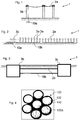
- Fig. 1 shows a side view of a possible general application of a grounding conductor or grounding device in the form of a mesh 10a for an aerial power cable 2a in an electrical power system 1.
- Fig. 2 shows a side view of a possible general application of a grounding conductor or a grounding device in the form of a ground-laid line 10b running along and electrically connected to a longitudinally far extending aerial power cable 2a in an electrical power system 1.
- Fig. 3 shows a side view of a possible general application of a grounding conductor or grounding device in the form of a ground-laid 10b line provided alongside a ground-laid power cable 2b between two power structures, such as two transformer stations 3b, in an electrical power system 1.
- a Grounding conductor 10a, 10b is intended for air and/or ground laid power line distribution network applications, where the grounding conductor 10a, 10b according to embodiments in particular is adapted to be laid underground or in water.
- the grounding conductor 10a, 10b is either a) see Fig. 1 and 2 provided in connection with or at a distance to an AC or DC power cable 2a, 2b such as an AC single or three phased power cable, or power structure, such as a pole 3a, a transformer station 3b, or a building, which power cable 2a, 2b or structure 3a, 3b is provided above ground, or b) see Fig. 3 provided in direct contact with or alongside said power cable 2b in the ground.
- the purpose of the grounding conductor 10a, 10b is to form a ground or earth potential to the power cable 2a, 2b or structure 3a, 3b.
- grounding conductors 10b are provided following, along, or being integrated with ground laid power cables 2b, see Fig. 3 . In some cases at least part of said grounding conductor 10a, 10b is provided following, along, or integrated with aerial power cables 3a, see Fig. 1 and 2 .
- the grounding conductor 10a may be applied in the ground near individual poles 3a, as shown in Fig. 1 , on site providing system ground, under transformers 3b, or close by buildings, e.g. by providing a mesh 10a, or can be applied following the power cable 2 and laid underground as a ground conductor 10b, see Fig. 2 .
- the grounding conductor 10a, 10b may be utilized comprising any suitable diameter as to form straight or twisted wires, strands, rods, or pipes.
- the earth symbol is provided simply to indicate that an earth potential is reached for the grounding conductor 10a, 10b in question and does not indent to show the position or the efficiency of the grounding conductor 10a, 10b in question.
- grounding conductors 10a, 10b discussed in connection with Figs. 1 - 3 comprise in accordance with the present invention grounding conductors 100 as discussed herein and in the following, with reference to Figs. 4 - 8B , 17, 20, and 21 .
- FIG. 4 shows a photo of cross section view cut through a grounding conductor 100 according to an embodiment of the invention.
- the conductor 100 comprises a conductive metal part comprising seven solid aluminium strands 120 twisted together, each strand being of an approx. equal diameter dw around 2.6 mm.
- Each strand 120 is individually sheathed with a conductive polymer material sheath 140 of generally uniform thickness ts around 0.3-0.4 mm.
- the conductive polymer material is a polypropylene matrix comprising a filler of conductive particulates in the form of carbon black.
- Figs. 5A, 5B - 8A, 8B show grounding conductors 100 according to four different embodiments of the invention, in perspective side view and in cross section view, respectively.
- Fig. 5A and 5B show a grounding conductor 100 comprising seven aluminium strands 120 of equal diameter d W around 3 mm: A central strand surrounded by six outer strands, each strand being coated or provided with a sheath of conductive polymer material of a thickness t S of around 0.3 mm.
- the strands are provided lengthwise along each other. Alternatively, they can be provided twisted or wound around each other lengthwise.
- the sheathed strands can be provided loosely along each other as shown, can be adhered together by e.g. heat-treating the polymer sheaths or by gluing, or can be kept together by a wire or paper jacket (not shown).
- Fig. 6A and 6B show a grounding conductor 100 comprising nine aluminium strands 120, eight being of equal cross sectional diameter d W1 around 3 mm surrounding a central strand 120a of a larger cross sectional diameter d W2 around 5 mm.
- Each strand 120, 120a is coated with a sheath 140 of conductive polymer material of a thickness t S of around 0.3 mm.
- the sheathed strands 120 are provided lengthwise along each other.
- the risk of all the strands being damaged during laying or use is reduced. Further, by providing such one surrounding layer or more layers of sheathed strands 120 around at least one central sheathed strand 120a, the central strand 120a or strands is/are better protected by these at least one layers of surrounding strands 120, which reduces the risk of damaging at least the central strand 120a or strands, and increases the overall grounding effect.
- Fig. 7A and 7B show a grounding conductor 100 with the same number, position, and cross sectional diameter of individually sheathed aluminium strands 120 as shown in Fig. 6A and 6B , further being surrounded by a jacket 160 having a uniform thickness tj1 of around 1 mm, e.g. provided by extrusion. Due to the provision of the eight surrounding sheathed strands 120, and a malleable jacket material, such as a polymer, such as a conductive polymer, the outer and inner surface of the jacket adapts its shape to form a cross sectional octagon. Note that the exposed jacket surface area size of the grounding conductor shown in Fig.
- Fig. 8A and 8B show a grounding conductor 100 with the same number, position, and cross sectional diameter of individually sheathed aluminium strands as shown in Fig. 6A and 6B , further being surrounded by a jacket 160 having a non-uniform thickness tj2 of around 1 mm at its thinnest and around 2.2 mm at its thickest part, e.g. provided by melt extrusion or by a downstream heating step.
- the cross sectional shape of the grounding conductor with jacket 160 is substantially round, and the polymer jacket material has entered over the outer surfaces of the sheathed eight surrounding sheathed strands, and optionally (not shown) in between the strands, to thus provide a better contact between the inner surface of the jacket 160 and the outside of the sheaths 140 thus jacketed.
- a further process step of compressing the jacket 160 during or after the extrusion may be applied.
- the external sheath surface or the external jacket surface of the grounding conductor 100 has a low friction coefficient enabling an easy laying in the ground.
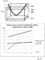
- Fig. 9 shows a schematic perspective drawing illustrating a setup for testing a grounding conductor to verify whether the grounding conductor is according to the present invention, showing a polyethylene container 900 comprising a volume of about 1 I liquid 905 consisting of a 1 vol% sodium sulphate solution, i.e. an aqueous electrolytic solution and at ambient temperatures.
- a length Is here 200 mm of a conductor under test 920 is submerged, being bent to be accommodated inside the container 900 and provided at its deepest point at a depth of around 0.5 meter.
- a copper plate electrode 910 near the bottom of the container and at a, constant between samples, minimum distance of 20-25 cm to the conductor under test 920.
- Electrode metal materials such as aluminium, as well as electrode sizes and shapes, such as a foil, can be contemplated by the skilled person, as well as container material, shape and size, as well as other positionings of the conductor, electrode and liquid level over conductor relative to each other. It may be advantageous to adapt these sizes to the current values being used, as well as the physical size of the conductor under test.
- a test current is applied running between said conductor under test 920 and the electrode 910 such that a potential can be measured over said conductor under test 920 and said electrode 910.
- all conductors being tested were submerged entirely along the length, one by one, and all comprising a single aluminium strand having a strand diameter dw of 3.06 mm, and when sheathed, was provided with a substantially uniform thickness of the conductive polymer sheath of around 0.3 mm.
- strand widths or conductor widths of between 5 mm and 30 mm, such as 20 mm - 25 mm can be tested.
- the conductors under test 920 were the following test samples for the first series of measurements according to the first procedure:
- Sample 1 was inserted into the sulphate solution of the above setup, and a first set test current of 1 mA was applied from one end of Sample 1 and to the electrode 910, such that a negative test potential was applied to said aluminium strand relative to said electrode, and the potential difference, named the sheathed-strand potential difference between the electrode and the Sample 1 was noted.
- a second set test current of 3 mA was applied, and so on along suitable intervals, such that a test current within a first test current range was provided there between, resulting here in measuring over a series of current and potential measurements being logged over said first current range from 1 mA to 10 mA.
- Sample 2 was inserted into the same sulphate solution of the above setup, and the electrical potential difference was measured from one end of Sample 2 and to the electrode 910, measuring a test series with the same intervals over the same first current range from 1 mA to 10 mA.
- the sheath material from Sample 1 was removed and a bare aluminium strand was provided, denoted Bare strand.
- Bare strand was inserted into the same sulphate solution of the above setup, and the electrical potential was measured from one end of the Bare strand and to the electrode 910, measuring over the same first current range from 1 mA to 10 mA.
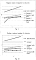
- Table 1 and 2 comprises the test results for test procedure one and two, respectively, and in Fig. 10 , 11 and 12 are shown diagram of the result achieved.
- the setup as shown in Fig. 9 illustrates one way how to provide for the first and second test procedures, however other setups can be contemplated by the skilled person, such as measuring according to the IEC standard 60229 corrosion test.
- the container was a copper tank comprising 100 I of the test solution in question, and the strand was 1.2 m long Iw and having 1 m thereof submerged into the solution at a depth of around 0.5 m, and provided substantially not bent therein.
- the tests according to the invention but of different setups provide the same indicator or criteria for determining the provision of a low potential difference during test for deciding which conductor is according to the invention.
- Test performed with DC potential Vtest in the order of 0.1 to 30 V depending on test conditions. When testing certain conventional or less suitable conducting polymer materials even higher potentials were measured, such as around 100-400 V.
- the provided grounding conductor according to the invention further lives up to the requirements of 1) withstanding a maximum of 50 V potential difference towards ground in extreme operation conditions 2) a max current of 50 ampere AC into the conductor at all times ⁇ between stations, line faults around 100-1000 ampere or more. It was dimensioned here to withstand 65 A/mm2 over 1 second for all grounding conductors.
- test voltage / test current range Length of strand in conducting liquid, sheath surface area contacting liquid, distance from strand surface to electrode (seem to influence the most), liquid volume, and the same depth being kept.
- a selection of similar lengths of the same grounding conductor according to the invention having a physical section as shown in Fig. 4 comprising seven equal diameter dw of around 3.06 mm aluminium strands, each individually sheathed by an as above identified conductive polymer material having a uniform thickness ts around 0.3 mm, and each provided not adhering to mutually and twisted around each other at a twist length of around 14 cm.
- the lightning tests were carried out to test the performance of a grounding conductor sample according to the present invention as regards to satisfactory performance during lightning or fault currents in the surrounding ground soil.
- the sample was a grounding conductor from one strand wound by seven aluminium filaments, comprising a surrounding sheath.
- a lightning test setup was provided as seen in Fig. 13 : A container around 1.5 m wide x 1 m long x 1 m high was provided enclosing a copper plate for providing electrical earth potential to water saturated humus soil filled into the container on top of the copper plate for providing resistance and a current path there through.
- the sample length was such that one meter thereof was buried within the soil along and at around 20 cm from the copper plate, and having each sample end extending from the soil.
- the sample ends were attached to a Marx voltage generator for providing a steadily increased voltage up to 40 kV.
- Figs. 14A-14B illustrates another important advantage of the grounding conductor according to the invention.
- the resistance over the sheath of the sample is advantageously low with resistances of below 100 ⁇ cm, preferably below 50 ⁇ cm, more preferred below 30 ⁇ cm.
- Corrosion tests such as set out in IEC standard 60229, were also carried out. The purpose was to demonstrate that, in the event of local damage to a sheath, any consequential corrosion of the outer surface of the aluminium strand would remain virtually confined to the damaged area of covering, preferably reduced corrosion would be observed relative to a bare grounding conductor.
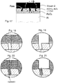
- Fig. 15 is shown a cut-out of an aluminium surface with no sheath, i.e. bare, such as one side surface of an aluminium strand along the length thereof. Aluminium surfaces will generally formulate a white, protective layer of oxygen induced corrosion in the form of aluminium oxide if left unprotected from the atmosphere or water. As shown in Fig. 15 this aluminium oxide layer basically consists of amorphous Al 2 O 3 in two partial layers on top of each other, namely
- the thickness of the Al 2 O 3 layer increases with time, temperature, whether anodization was used, and the availability of oxygen. Even though the oxide layer is very tight, durable, has a melting temperature of 2.300° Celsius, and protects the aluminium surface from further corrosion, it can over time also become porous and pick up humidity, which then increases its corrosion susceptibility. Further, the density of Al 2 O 3 is higher in comparison to the aluminium metal itself, and the electrical resistivity of Al 2 O 3 is very high, 1x10 14 ⁇ cm.
- Sheath 1 is made from the conductive polymer material based on Low Density Polyethylene (LDPE) from Borealis by the trade name LE0563 added a conductive filler of carbon black.
- LDPE Low Density Polyethylene
- the Sheath 1 is applied by extrusion and by the combination of added carbon black, extrusion and polyethylene, the viscosity of the mix may increase, because when adding a higher content of low size conductive particles, then the viscosity of the mix tends to increase. As a result the polymer compound may not enter deep enough, inside the pores, and into contact with the aluminium oxide layer.
- the "islands" of hydrated aluminium in contact with the polymer will, at the current densities and potentials experienced when providing ground for power cables, simply form too high potential walls for the very low current to flow during normal operation of the electrical power system. Further, any humidity and leaks from any damages of the polymer tend to gather in the pores and inside the hydrated aluminium, which increases corrosion there.
- Sheath 2 is made from a conductive polymer and the grounding conductor according to the invention is provided.
- the aluminium oxide and sheath are in good surface contact with each other, also in the bottom of the pores, and this good surface contact may provide a preferred "road" for the electrical current to go along, when needed.
- each conductive polymer may be provided in each conductive polymer according to the various embodiments discussed herein, which embodiments are:
Landscapes
- Chemical & Material Sciences (AREA)
- Health & Medical Sciences (AREA)
- Chemical Kinetics & Catalysis (AREA)
- Medicinal Chemistry (AREA)
- Polymers & Plastics (AREA)
- Organic Chemistry (AREA)
- Physics & Mathematics (AREA)
- Spectroscopy & Molecular Physics (AREA)
- Manufacturing Of Electrical Connectors (AREA)
- Insulated Conductors (AREA)
Claims (12)
- Erdungsleiter (10a, 10b, 100) zur Bildung eines Masse- oder Erdpotentials an einem Stromkabel (2a, 2b) oder einer Struktur (3a, 3b) und für elektrischen Kontakt mit einer umgebenden Umwelt, um im Wesentlichen entlang der gesamten Länge des Erdungsleiters (10a, 10b, 100) ein Erdungspotenzial bereitzustellen, wo dieser im Boden verlegt ist, der Erdungsleiter (10a, 10b, 100) umfassend mehrere leitfähige Aluminiumlitzen (120), die mit einer Scheide (140) versehen sind, die ein elektrisch leitfähiges Polymermaterial umfasst, wobei
der Erdungsleiter (10a, 10b, 100) die mehreren leitfähigen Aluminiumlitzen (120) umfasst,
wobei
jede dieser Litzen (120) mit mindestens einer Scheide (140) versehen ist, die ein elektrisch leitfähiges Polymermaterial umfasst, das einen Volumenwiderstand (p) unter 100 Qcm aufweist, dadurch gekennzeichnet, dass mindestens einige der mehreren leitfähigen Aluminiumlitzen (120) eine zentral bereitgestellte leitfähige Aluminiumlitze (120a) der mehreren leitfähigen Aluminiumlitzen (120) vollständig umgeben. - Erdungsleiter (10a, 10b, 100) nach Anspruch 1, wobei ein Übergangswiderstand für eine der mehreren leitfähigen Aluminiumlitzen (120), die mit mindestens einer Scheide (140) versehen ist, gegenüber eines umgebenden Mediums geringer ist, als ein Übergangswiderstand für eine blanke leitfähige Aluminiumlitze der mehreren leitfähigen Aluminiumlitzen demselben umgebenden Medium gegenüber.
- Erdungsleiter (10a, 10b, 100) nach einem der vorhergehenden Ansprüche, wobei das leitfähige Polymermaterial ein Polyolefin, das mit einem Elastomer gemischt ist, 10 - 40 % hochreines kohlehaltiges Material und ein Antioxidationsmittel umfasst.
- Erdungsleiter (10a, 10b, 100) nach Anspruch 1 oder 2, wobei das leitfähige Polymermaterial Polypropylen, das mit einem Ethylen-/Propylenelastomer gemischt ist, 23 - 30 % Ruß und ein phenolisches Antioxidationsmittel umfasst.
- Erdungsleiter (10a, 10b, 100) nach Anspruch 1 oder 2, wobei das leitfähige Polymermaterial 62 - 68% Polypropylen, das mit einem Ethylen-/Propylenelastomer gemischt ist, 23 - 30 % Ruß und 2 - 4% phenolisches Antioxidationsmittel umfasst.
- Erdungsleiter (10a, 10b, 100) nach Anspruch 1 oder 2, wobei das leitfähige Polymermaterial 25 - 70% Polypropylen, 15 - 55% Ethylen-Propylenelastomer, 23 - 30 % Ruß und 2 - 4% phenolisches Antioxidationsmittel umfasst.
- Erdungsleiter (10a, 10b, 100) nach einem der vorhergehenden Ansprüche, wobei jede der mehreren leitfähigen Aluminiumlitzen (120), die mit einer Scheide (140) versehen sind, einen Aluminiumlitzendurchmesser (dw) innerhalb eines Bereichs von 0,2 - 25 mm und eine Scheidendicke (ts) innerhalb eines Bereichs von 0,2 - 0,7 mm aufweist.
- Stromversorgungssystem (1), umfassend ein Stromkabel (2a, 2b) oder eine Struktur (3a, 3b), die durch einen Erdungsleiter (10a, 10b, 100) nach einem der Ansprüche 1 bis 7 geerdet ist, der im Boden vergraben ist und entlang seiner ganzen Länge in Erdungskontakt steht.
- Stromversorgungssystem (1) nach Anspruch 8, umfassend das Stromkabel (2b), wobei der Erdungsleiter (10b) mindestens entlang einer Länge des Stromkabels (2b) neben diesem und in Kontakt mit einer Außenfläche des Stromkabels (2b) bereitgestellt ist.
- Stromversorgungssystem (1) nach Anspruch 8, wobei das Stromkabel (2a) ein Antennenkabel (2a) ist und der Erdungsleiter (10a, 10b) im Boden und entlang zumindest eines Teils des Stromkabels (2a) bereitgestellt ist.
- Verwendung eines Erdungsleiters (10a, 10b, 100) nach einem der Ansprüche 1 bis 7 als Erdungsanschluss (10a, 10b, 100), der parallel zu einem Stromkabel (2a, 2b) zwischen zwei Stromversorgungsstrukturen (3a, 3b) verläuft, um ein Erdungspotential für das Stromkabel (2a, 2b) oder die Stromversorgungsstruktur (3a, 3b) bereitzustellen, wobei der Erdungsleiter (10a, 10b, 100) unterirdisch verlegt ist, um in elektrischem Kontakt mit einer umgebenden Umwelt zu stehen, um entlang im Wesentlichen der gesamten Länge des Erdungsleiters (10a, 10b, 100) ein Erdungspotenzial bereitzustellen.
- Verwendung eines Erdungsleiters (10a, 10b, 100) nach Anspruch 11, wobei die beiden Stromversorgungsstrukturen (3b) Transformatorstationen sind (3b).
Priority Applications (2)
| Application Number | Priority Date | Filing Date | Title |
|---|---|---|---|
| PL15839134T PL3036747T3 (pl) | 2014-11-07 | 2015-10-09 | Przewód uziemiający, elektryczny system zasilający i zastosowanie przewodu uziemiającego |
| EP15839134.2A EP3036747B1 (de) | 2014-11-07 | 2015-10-09 | Erdungsleiter-stromversorgungssystem und verwendung des erdungsleiters |
Applications Claiming Priority (3)
| Application Number | Priority Date | Filing Date | Title |
|---|---|---|---|
| EP14192339 | 2014-11-07 | ||
| PCT/DK2015/050308 WO2016070880A1 (en) | 2014-11-07 | 2015-10-09 | Grounding conductor, electrical power system and use of grounding conductor |
| EP15839134.2A EP3036747B1 (de) | 2014-11-07 | 2015-10-09 | Erdungsleiter-stromversorgungssystem und verwendung des erdungsleiters |
Publications (3)
| Publication Number | Publication Date |
|---|---|
| EP3036747A1 EP3036747A1 (de) | 2016-06-29 |
| EP3036747A4 EP3036747A4 (de) | 2016-10-19 |
| EP3036747B1 true EP3036747B1 (de) | 2019-06-19 |
Family
ID=51897137
Family Applications (1)
| Application Number | Title | Priority Date | Filing Date |
|---|---|---|---|
| EP15839134.2A Active EP3036747B1 (de) | 2014-11-07 | 2015-10-09 | Erdungsleiter-stromversorgungssystem und verwendung des erdungsleiters |
Country Status (8)
| Country | Link |
|---|---|
| US (1) | US10181362B2 (de) |
| EP (1) | EP3036747B1 (de) |
| AU (1) | AU2015342276A1 (de) |
| CA (1) | CA2966406A1 (de) |
| DK (1) | DK3036747T3 (de) |
| PL (1) | PL3036747T3 (de) |
| RU (1) | RU2690176C2 (de) |
| WO (1) | WO2016070880A1 (de) |
Families Citing this family (7)
| Publication number | Priority date | Publication date | Assignee | Title |
|---|---|---|---|---|
| JP6746438B2 (ja) * | 2016-09-07 | 2020-08-26 | 矢崎総業株式会社 | シールド電線及びワイヤーハーネス |
| TWI680632B (zh) * | 2017-10-03 | 2019-12-21 | 首利實業股份有限公司 | 高功率電源供應器之電路結構 |
| US11145434B2 (en) | 2019-05-08 | 2021-10-12 | Erico International Corporation | Low voltage power conductor and system |
| CA3095393A1 (en) | 2019-10-11 | 2021-04-11 | Matergenics, Inc. | Atmospheric corrosivity mapping method and apparatus |
| US12015255B2 (en) * | 2021-04-28 | 2024-06-18 | David Donald Behrendt | Grounding rod |
| CN113541114B (zh) * | 2021-06-30 | 2023-03-07 | 国网河南省电力公司电力科学研究院 | 一种基于地中屏障的埋地管网入地电流防护方法 |
| CN114243319B (zh) * | 2021-12-22 | 2024-05-31 | 国网甘肃省电力公司经济技术研究院 | 一种电力系统接地装置 |
Family Cites Families (19)
| Publication number | Priority date | Publication date | Assignee | Title |
|---|---|---|---|---|
| US3297814A (en) * | 1964-11-02 | 1967-01-10 | Northern Electric Co | Semi-conducting sheath selfsupporting cable |
| US3632720A (en) * | 1969-03-03 | 1972-01-04 | Dow Chemical Co | Method of fabricating cables |
| US3660592A (en) | 1970-02-27 | 1972-05-02 | Haveg Industries Inc | Anti-corona electrical conductor |
| US3571613A (en) | 1970-05-20 | 1971-03-23 | Anaconda Wire & Cable Co | Cable system |
| US3816644A (en) * | 1973-03-30 | 1974-06-11 | Belden Corp | Low noise cord with non-metallic shield |
| US3794752A (en) | 1973-05-30 | 1974-02-26 | Anaconda Co | High voltage cable system free from metallic shielding |
| US4025715A (en) * | 1976-03-15 | 1977-05-24 | Alcan Aluminum Corporation | Shielded electric cable |
| DE2942925A1 (de) * | 1979-10-24 | 1981-05-07 | Kabel- und Metallwerke Gutehoffnungshütte AG, 3000 Hannover | Feuchtigkeitsgeschuetztes elektrisches kabel |
| JPS59125018U (ja) * | 1983-02-07 | 1984-08-23 | 古河電気工業株式会社 | ゴム、プラスチツク絶縁電力ケ−ブル |
| JPS59211975A (ja) | 1983-05-16 | 1984-11-30 | カヤ商事株式会社 | 接地用メツシユ電極 |
| JPS6062070A (ja) | 1983-08-19 | 1985-04-10 | レイケム・コーポレイシヨン | 接地装置 |
| JPH10223279A (ja) | 1996-11-22 | 1998-08-21 | Nippon Chiko Co Ltd | 電気設備の接地工法およびこれに用いる接地電極 |
| MX2007004517A (es) | 2004-10-15 | 2007-06-20 | Gen Cable Technologies Corp | Cable electrico protegido contra falla mejorado. |
| EP1937763A2 (de) | 2005-08-08 | 2008-07-02 | Cabot Corporation | Polymere zusammensetzungen mit nanoröhrchen |
| US7754969B2 (en) * | 2007-06-08 | 2010-07-13 | Southwire Company | Armored cable with integral support |
| WO2011159446A1 (en) * | 2010-06-18 | 2011-12-22 | Union Carbide Chemicals & Plastics Technology Llc | Electrically conductive, olefin multiblock copolymer compositions |
| US9412498B2 (en) * | 2012-04-27 | 2016-08-09 | Draka Comteq Bv | Electric cable, in particular a data transmission cable, equipped with multi-layer strip-type screening sheet |
| CN202677864U (zh) * | 2012-06-29 | 2013-01-16 | 江苏亨通线缆科技有限公司 | 应用于铁路系统的双金属地线 |
| US10147523B2 (en) * | 2014-09-09 | 2018-12-04 | Panasonic Avionics Corporation | Cable, method of manufacture, and cable assembly |
-
2015
- 2015-10-09 EP EP15839134.2A patent/EP3036747B1/de active Active
- 2015-10-09 US US15/522,046 patent/US10181362B2/en active Active
- 2015-10-09 RU RU2017119658A patent/RU2690176C2/ru active
- 2015-10-09 WO PCT/DK2015/050308 patent/WO2016070880A1/en active Application Filing
- 2015-10-09 PL PL15839134T patent/PL3036747T3/pl unknown
- 2015-10-09 AU AU2015342276A patent/AU2015342276A1/en not_active Abandoned
- 2015-10-09 CA CA2966406A patent/CA2966406A1/en not_active Abandoned
- 2015-10-09 DK DK15839134.2T patent/DK3036747T3/da active
Non-Patent Citations (1)
| Title |
|---|
| None * |
Also Published As
| Publication number | Publication date |
|---|---|
| EP3036747A4 (de) | 2016-10-19 |
| US20170316846A1 (en) | 2017-11-02 |
| AU2015342276A1 (en) | 2017-05-18 |
| US10181362B2 (en) | 2019-01-15 |
| PL3036747T3 (pl) | 2020-02-28 |
| RU2690176C2 (ru) | 2019-05-31 |
| EP3036747A1 (de) | 2016-06-29 |
| RU2017119658A (ru) | 2018-12-07 |
| WO2016070880A1 (en) | 2016-05-12 |
| CA2966406A1 (en) | 2016-05-12 |
| RU2017119658A3 (de) | 2019-03-28 |
| DK3036747T3 (da) | 2019-09-23 |
Similar Documents
| Publication | Publication Date | Title |
|---|---|---|
| EP3036747B1 (de) | Erdungsleiter-stromversorgungssystem und verwendung des erdungsleiters | |
| KR20160121873A (ko) | 전력 케이블 | |
| CN109378136B (zh) | 一种环保中压电力电缆的制造方法及电缆 | |
| CN202076018U (zh) | 一种同轴电缆 | |
| US20100231228A1 (en) | High voltage electric cable | |
| AU2015416536B2 (en) | Fire resistant electric cable | |
| KR20170012003A (ko) | 케이블의 내수성 평가 방법 | |
| CA2689460C (en) | Swellable tapes and yarns to replace strand filling compounds | |
| KR102249186B1 (ko) | Dc 케이블의 체적저항측정 시스템 | |
| US10749277B2 (en) | Intermediate connection system for ultra-high-voltage direct current power cable | |
| KR20170026752A (ko) | 케이블의 내수성 평가 방법 | |
| US11574748B2 (en) | Ultra high voltage direct current power cable system | |
| CN203260362U (zh) | 高压和超高压柔性直流输电光纤复合挤出绝缘电力电缆 | |
| Silva et al. | Field behavior on polymer-covered overhead conductors submitted to natural aging on diverse weather and geographic conditions in Brazil | |
| CN203520938U (zh) | 一种用于电动汽车交流充电的充电电缆 | |
| EP2099038A1 (de) | Elektrischer Isolator und Verfahren zur Herstellung eines derartigen elektrischen Isolators | |
| CN209674977U (zh) | 城市电网供电系统用10kV电缆 | |
| CN103123826B (zh) | 高压和超高压柔性直流输电光纤复合挤出绝缘电力电缆 | |
| Adhikari | Analysis of Partial Discharge Measurements on Medium Voltage Covered Conductor for Overhead Transmission Lines | |
| AU2016202308B2 (en) | Down conductor | |
| Slade | High-voltage rubber-insulated submarine power cables | |
| CZ272795A3 (en) | HIGH-VOLTAGE CONDUCTOR FOR OVERHEAD LINE AND FOR VOLTAGE 60 kV AND HIGHER | |
| CABLES | High voltage cables | |
| CN207624410U (zh) | 一种电力和控制用光电复合托架电缆 | |
| CN119296862A (zh) | 一种铅护套计算机电缆 |
Legal Events
| Date | Code | Title | Description |
|---|---|---|---|
| PUAI | Public reference made under article 153(3) epc to a published international application that has entered the european phase |
Free format text: ORIGINAL CODE: 0009012 |
|
| 17P | Request for examination filed |
Effective date: 20160317 |
|
| AK | Designated contracting states |
Kind code of ref document: A1 Designated state(s): AL AT BE BG CH CY CZ DE DK EE ES FI FR GB GR HR HU IE IS IT LI LT LU LV MC MK MT NL NO PL PT RO RS SE SI SK SM TR |
|
| AX | Request for extension of the european patent |
Extension state: BA ME |
|
| A4 | Supplementary search report drawn up and despatched |
Effective date: 20160921 |
|
| RIC1 | Information provided on ipc code assigned before grant |
Ipc: H01R 4/66 20060101AFI20160915BHEP Ipc: H02G 13/00 20060101ALI20160915BHEP |
|
| STAA | Information on the status of an ep patent application or granted ep patent |
Free format text: STATUS: EXAMINATION IS IN PROGRESS |
|
| 17Q | First examination report despatched |
Effective date: 20161104 |
|
| DAV | Request for validation of the european patent (deleted) | ||
| DAX | Request for extension of the european patent (deleted) | ||
| GRAP | Despatch of communication of intention to grant a patent |
Free format text: ORIGINAL CODE: EPIDOSNIGR1 |
|
| STAA | Information on the status of an ep patent application or granted ep patent |
Free format text: STATUS: GRANT OF PATENT IS INTENDED |
|
| RIC1 | Information provided on ipc code assigned before grant |
Ipc: H02G 13/00 20060101ALI20180525BHEP Ipc: H01B 1/12 20060101ALI20180525BHEP Ipc: H01B 1/02 20060101ALI20180525BHEP Ipc: H01R 4/66 20060101AFI20180525BHEP |
|
| INTG | Intention to grant announced |
Effective date: 20180620 |
|
| GRAJ | Information related to disapproval of communication of intention to grant by the applicant or resumption of examination proceedings by the epo deleted |
Free format text: ORIGINAL CODE: EPIDOSDIGR1 |
|
| STAA | Information on the status of an ep patent application or granted ep patent |
Free format text: STATUS: EXAMINATION IS IN PROGRESS |
|
| REG | Reference to a national code |
Ref country code: DE Ref legal event code: R079 Ref document number: 602015032445 Country of ref document: DE Free format text: PREVIOUS MAIN CLASS: H01B0001020000 Ipc: H01R0004660000 |
|
| INTC | Intention to grant announced (deleted) | ||
| RIC1 | Information provided on ipc code assigned before grant |
Ipc: H02G 13/00 20060101ALI20181116BHEP Ipc: H01B 1/12 20060101ALI20181116BHEP Ipc: H01B 1/02 20060101ALI20181116BHEP Ipc: H01R 4/66 20060101AFI20181116BHEP Ipc: C08L 23/12 20060101ALI20181116BHEP |
|
| GRAP | Despatch of communication of intention to grant a patent |
Free format text: ORIGINAL CODE: EPIDOSNIGR1 |
|
| STAA | Information on the status of an ep patent application or granted ep patent |
Free format text: STATUS: GRANT OF PATENT IS INTENDED |
|
| INTG | Intention to grant announced |
Effective date: 20190108 |
|
| GRAS | Grant fee paid |
Free format text: ORIGINAL CODE: EPIDOSNIGR3 |
|
| GRAA | (expected) grant |
Free format text: ORIGINAL CODE: 0009210 |
|
| STAA | Information on the status of an ep patent application or granted ep patent |
Free format text: STATUS: THE PATENT HAS BEEN GRANTED |
|
| RIN1 | Information on inventor provided before grant (corrected) |
Inventor name: GLEICH, DIETMAR Inventor name: ANDERSSON, HANS CHRISTIAN Inventor name: GATU, ANDERS JONAS Inventor name: HAGMAN, LARS INGVAR Inventor name: EFRAIMSSON, LARS Inventor name: HANSSON, IVARS LARS SUNE Inventor name: ASMOLA, TOMMY K. VALDEMAR |
|
| AK | Designated contracting states |
Kind code of ref document: B1 Designated state(s): AL AT BE BG CH CY CZ DE DK EE ES FI FR GB GR HR HU IE IS IT LI LT LU LV MC MK MT NL NO PL PT RO RS SE SI SK SM TR |
|
| REG | Reference to a national code |
Ref country code: GB Ref legal event code: FG4D |
|
| REG | Reference to a national code |
Ref country code: CH Ref legal event code: EP |
|
| REG | Reference to a national code |
Ref country code: IE Ref legal event code: FG4D |
|
| REG | Reference to a national code |
Ref country code: AT Ref legal event code: REF Ref document number: 1146688 Country of ref document: AT Kind code of ref document: T Effective date: 20190715 |
|
| REG | Reference to a national code |
Ref country code: DE Ref legal event code: R096 Ref document number: 602015032445 Country of ref document: DE |
|
| REG | Reference to a national code |
Ref country code: NO Ref legal event code: T2 Effective date: 20190619 Ref country code: DK Ref legal event code: T3 Effective date: 20190916 |
|
| REG | Reference to a national code |
Ref country code: SE Ref legal event code: TRGR |
|
| REG | Reference to a national code |
Ref country code: NL Ref legal event code: MP Effective date: 20190619 |
|
| PG25 | Lapsed in a contracting state [announced via postgrant information from national office to epo] |
Ref country code: HR Free format text: LAPSE BECAUSE OF FAILURE TO SUBMIT A TRANSLATION OF THE DESCRIPTION OR TO PAY THE FEE WITHIN THE PRESCRIBED TIME-LIMIT Effective date: 20190619 Ref country code: LT Free format text: LAPSE BECAUSE OF FAILURE TO SUBMIT A TRANSLATION OF THE DESCRIPTION OR TO PAY THE FEE WITHIN THE PRESCRIBED TIME-LIMIT Effective date: 20190619 Ref country code: AL Free format text: LAPSE BECAUSE OF FAILURE TO SUBMIT A TRANSLATION OF THE DESCRIPTION OR TO PAY THE FEE WITHIN THE PRESCRIBED TIME-LIMIT Effective date: 20190619 |
|
| REG | Reference to a national code |
Ref country code: LT Ref legal event code: MG4D |
|
| PG25 | Lapsed in a contracting state [announced via postgrant information from national office to epo] |
Ref country code: BG Free format text: LAPSE BECAUSE OF FAILURE TO SUBMIT A TRANSLATION OF THE DESCRIPTION OR TO PAY THE FEE WITHIN THE PRESCRIBED TIME-LIMIT Effective date: 20190919 Ref country code: RS Free format text: LAPSE BECAUSE OF FAILURE TO SUBMIT A TRANSLATION OF THE DESCRIPTION OR TO PAY THE FEE WITHIN THE PRESCRIBED TIME-LIMIT Effective date: 20190619 Ref country code: LV Free format text: LAPSE BECAUSE OF FAILURE TO SUBMIT A TRANSLATION OF THE DESCRIPTION OR TO PAY THE FEE WITHIN THE PRESCRIBED TIME-LIMIT Effective date: 20190619 Ref country code: GR Free format text: LAPSE BECAUSE OF FAILURE TO SUBMIT A TRANSLATION OF THE DESCRIPTION OR TO PAY THE FEE WITHIN THE PRESCRIBED TIME-LIMIT Effective date: 20190920 |
|
| REG | Reference to a national code |
Ref country code: AT Ref legal event code: MK05 Ref document number: 1146688 Country of ref document: AT Kind code of ref document: T Effective date: 20190619 |
|
| PG25 | Lapsed in a contracting state [announced via postgrant information from national office to epo] |
Ref country code: NL Free format text: LAPSE BECAUSE OF FAILURE TO SUBMIT A TRANSLATION OF THE DESCRIPTION OR TO PAY THE FEE WITHIN THE PRESCRIBED TIME-LIMIT Effective date: 20190619 Ref country code: SK Free format text: LAPSE BECAUSE OF FAILURE TO SUBMIT A TRANSLATION OF THE DESCRIPTION OR TO PAY THE FEE WITHIN THE PRESCRIBED TIME-LIMIT Effective date: 20190619 Ref country code: RO Free format text: LAPSE BECAUSE OF FAILURE TO SUBMIT A TRANSLATION OF THE DESCRIPTION OR TO PAY THE FEE WITHIN THE PRESCRIBED TIME-LIMIT Effective date: 20190619 Ref country code: PT Free format text: LAPSE BECAUSE OF FAILURE TO SUBMIT A TRANSLATION OF THE DESCRIPTION OR TO PAY THE FEE WITHIN THE PRESCRIBED TIME-LIMIT Effective date: 20191021 Ref country code: EE Free format text: LAPSE BECAUSE OF FAILURE TO SUBMIT A TRANSLATION OF THE DESCRIPTION OR TO PAY THE FEE WITHIN THE PRESCRIBED TIME-LIMIT Effective date: 20190619 Ref country code: AT Free format text: LAPSE BECAUSE OF FAILURE TO SUBMIT A TRANSLATION OF THE DESCRIPTION OR TO PAY THE FEE WITHIN THE PRESCRIBED TIME-LIMIT Effective date: 20190619 |
|
| PG25 | Lapsed in a contracting state [announced via postgrant information from national office to epo] |
Ref country code: IS Free format text: LAPSE BECAUSE OF FAILURE TO SUBMIT A TRANSLATION OF THE DESCRIPTION OR TO PAY THE FEE WITHIN THE PRESCRIBED TIME-LIMIT Effective date: 20191019 Ref country code: SM Free format text: LAPSE BECAUSE OF FAILURE TO SUBMIT A TRANSLATION OF THE DESCRIPTION OR TO PAY THE FEE WITHIN THE PRESCRIBED TIME-LIMIT Effective date: 20190619 Ref country code: ES Free format text: LAPSE BECAUSE OF FAILURE TO SUBMIT A TRANSLATION OF THE DESCRIPTION OR TO PAY THE FEE WITHIN THE PRESCRIBED TIME-LIMIT Effective date: 20190619 Ref country code: IT Free format text: LAPSE BECAUSE OF FAILURE TO SUBMIT A TRANSLATION OF THE DESCRIPTION OR TO PAY THE FEE WITHIN THE PRESCRIBED TIME-LIMIT Effective date: 20190619 |
|
| PG25 | Lapsed in a contracting state [announced via postgrant information from national office to epo] |
Ref country code: TR Free format text: LAPSE BECAUSE OF FAILURE TO SUBMIT A TRANSLATION OF THE DESCRIPTION OR TO PAY THE FEE WITHIN THE PRESCRIBED TIME-LIMIT Effective date: 20190619 |
|
| PG25 | Lapsed in a contracting state [announced via postgrant information from national office to epo] |
Ref country code: MC Free format text: LAPSE BECAUSE OF FAILURE TO SUBMIT A TRANSLATION OF THE DESCRIPTION OR TO PAY THE FEE WITHIN THE PRESCRIBED TIME-LIMIT Effective date: 20190619 Ref country code: IS Free format text: LAPSE BECAUSE OF FAILURE TO SUBMIT A TRANSLATION OF THE DESCRIPTION OR TO PAY THE FEE WITHIN THE PRESCRIBED TIME-LIMIT Effective date: 20200224 |
|
| REG | Reference to a national code |
Ref country code: CH Ref legal event code: PL |
|
| REG | Reference to a national code |
Ref country code: DE Ref legal event code: R097 Ref document number: 602015032445 Country of ref document: DE |
|
| PLBE | No opposition filed within time limit |
Free format text: ORIGINAL CODE: 0009261 |
|
| STAA | Information on the status of an ep patent application or granted ep patent |
Free format text: STATUS: NO OPPOSITION FILED WITHIN TIME LIMIT |
|
| PG2D | Information on lapse in contracting state deleted |
Ref country code: IS |
|
| PG25 | Lapsed in a contracting state [announced via postgrant information from national office to epo] |
Ref country code: LU Free format text: LAPSE BECAUSE OF NON-PAYMENT OF DUE FEES Effective date: 20191009 Ref country code: LI Free format text: LAPSE BECAUSE OF NON-PAYMENT OF DUE FEES Effective date: 20191031 Ref country code: CH Free format text: LAPSE BECAUSE OF NON-PAYMENT OF DUE FEES Effective date: 20191031 |
|
| 26N | No opposition filed |
Effective date: 20200603 |
|
| REG | Reference to a national code |
Ref country code: BE Ref legal event code: MM Effective date: 20191031 |
|
| PG25 | Lapsed in a contracting state [announced via postgrant information from national office to epo] |
Ref country code: BE Free format text: LAPSE BECAUSE OF NON-PAYMENT OF DUE FEES Effective date: 20191031 Ref country code: SI Free format text: LAPSE BECAUSE OF FAILURE TO SUBMIT A TRANSLATION OF THE DESCRIPTION OR TO PAY THE FEE WITHIN THE PRESCRIBED TIME-LIMIT Effective date: 20190619 |
|
| PG25 | Lapsed in a contracting state [announced via postgrant information from national office to epo] |
Ref country code: IE Free format text: LAPSE BECAUSE OF NON-PAYMENT OF DUE FEES Effective date: 20191009 |
|
| PG25 | Lapsed in a contracting state [announced via postgrant information from national office to epo] |
Ref country code: CY Free format text: LAPSE BECAUSE OF FAILURE TO SUBMIT A TRANSLATION OF THE DESCRIPTION OR TO PAY THE FEE WITHIN THE PRESCRIBED TIME-LIMIT Effective date: 20190619 |
|
| PG25 | Lapsed in a contracting state [announced via postgrant information from national office to epo] |
Ref country code: HU Free format text: LAPSE BECAUSE OF FAILURE TO SUBMIT A TRANSLATION OF THE DESCRIPTION OR TO PAY THE FEE WITHIN THE PRESCRIBED TIME-LIMIT; INVALID AB INITIO Effective date: 20151009 Ref country code: MT Free format text: LAPSE BECAUSE OF FAILURE TO SUBMIT A TRANSLATION OF THE DESCRIPTION OR TO PAY THE FEE WITHIN THE PRESCRIBED TIME-LIMIT Effective date: 20190619 |
|
| PG25 | Lapsed in a contracting state [announced via postgrant information from national office to epo] |
Ref country code: MK Free format text: LAPSE BECAUSE OF FAILURE TO SUBMIT A TRANSLATION OF THE DESCRIPTION OR TO PAY THE FEE WITHIN THE PRESCRIBED TIME-LIMIT Effective date: 20190619 |
|
| P01 | Opt-out of the competence of the unified patent court (upc) registered |
Effective date: 20230520 |
|
| PGFP | Annual fee paid to national office [announced via postgrant information from national office to epo] |
Ref country code: CZ Payment date: 20240910 Year of fee payment: 10 |
|
| PGFP | Annual fee paid to national office [announced via postgrant information from national office to epo] |
Ref country code: DE Payment date: 20241018 Year of fee payment: 10 |
|
| PGFP | Annual fee paid to national office [announced via postgrant information from national office to epo] |
Ref country code: NO Payment date: 20241021 Year of fee payment: 10 |
|
| PGFP | Annual fee paid to national office [announced via postgrant information from national office to epo] |
Ref country code: DK Payment date: 20241017 Year of fee payment: 10 |
|
| PGFP | Annual fee paid to national office [announced via postgrant information from national office to epo] |
Ref country code: PL Payment date: 20241001 Year of fee payment: 10 Ref country code: FI Payment date: 20241017 Year of fee payment: 10 |
|
| PGFP | Annual fee paid to national office [announced via postgrant information from national office to epo] |
Ref country code: GB Payment date: 20241017 Year of fee payment: 10 |
|
| PGFP | Annual fee paid to national office [announced via postgrant information from national office to epo] |
Ref country code: FR Payment date: 20241017 Year of fee payment: 10 |
|
| PGFP | Annual fee paid to national office [announced via postgrant information from national office to epo] |
Ref country code: SE Payment date: 20241018 Year of fee payment: 10 |