EP3036533B1 - Methods for fabricating platelets of a monochromator for x-ray photoelectron spectroscopy - Google Patents
Methods for fabricating platelets of a monochromator for x-ray photoelectron spectroscopy Download PDFInfo
- Publication number
- EP3036533B1 EP3036533B1 EP14837703.9A EP14837703A EP3036533B1 EP 3036533 B1 EP3036533 B1 EP 3036533B1 EP 14837703 A EP14837703 A EP 14837703A EP 3036533 B1 EP3036533 B1 EP 3036533B1
- Authority
- EP
- European Patent Office
- Prior art keywords
- crystal
- top surface
- measuring
- ray
- monochromator
- Prior art date
- Legal status (The legal status is an assumption and is not a legal conclusion. Google has not performed a legal analysis and makes no representation as to the accuracy of the status listed.)
- Active
Links
Images



Classifications
-
- G—PHYSICS
- G01—MEASURING; TESTING
- G01N—INVESTIGATING OR ANALYSING MATERIALS BY DETERMINING THEIR CHEMICAL OR PHYSICAL PROPERTIES
- G01N23/00—Investigating or analysing materials by the use of wave or particle radiation, e.g. X-rays or neutrons, not covered by groups G01N3/00 – G01N17/00, G01N21/00 or G01N22/00
- G01N23/20—Investigating or analysing materials by the use of wave or particle radiation, e.g. X-rays or neutrons, not covered by groups G01N3/00 – G01N17/00, G01N21/00 or G01N22/00 by using diffraction of the radiation by the materials, e.g. for investigating crystal structure; by using scattering of the radiation by the materials, e.g. for investigating non-crystalline materials; by using reflection of the radiation by the materials
-
- G—PHYSICS
- G01—MEASURING; TESTING
- G01N—INVESTIGATING OR ANALYSING MATERIALS BY DETERMINING THEIR CHEMICAL OR PHYSICAL PROPERTIES
- G01N23/00—Investigating or analysing materials by the use of wave or particle radiation, e.g. X-rays or neutrons, not covered by groups G01N3/00 – G01N17/00, G01N21/00 or G01N22/00
- G01N23/22—Investigating or analysing materials by the use of wave or particle radiation, e.g. X-rays or neutrons, not covered by groups G01N3/00 – G01N17/00, G01N21/00 or G01N22/00 by measuring secondary emission from the material
- G01N23/227—Measuring photoelectric effect, e.g. photoelectron emission microscopy [PEEM]
- G01N23/2273—Measuring photoelectron spectrum, e.g. electron spectroscopy for chemical analysis [ESCA] or X-ray photoelectron spectroscopy [XPS]
-
- G—PHYSICS
- G21—NUCLEAR PHYSICS; NUCLEAR ENGINEERING
- G21K—HANDLING OF PARTICLES OR IONISING RADIATION NOT OTHERWISE PROVIDED FOR; IRRADIATION DEVICES; GAMMA RAY OR X-RAY MICROSCOPES
- G21K1/00—Arrangements for handling particles or ionising radiation, e.g. focusing or moderating
- G21K1/06—Arrangements for handling particles or ionising radiation, e.g. focusing or moderating using diffraction, refraction or reflection, e.g. monochromators
-
- H—ELECTRICITY
- H01—ELECTRIC ELEMENTS
- H01J—ELECTRIC DISCHARGE TUBES OR DISCHARGE LAMPS
- H01J37/00—Discharge tubes with provision for introducing objects or material to be exposed to the discharge, e.g. for the purpose of examination or processing thereof
- H01J37/252—Tubes for spot-analysing by electron or ion beams; Microanalysers
- H01J37/256—Tubes for spot-analysing by electron or ion beams; Microanalysers using scanning beams
-
- B—PERFORMING OPERATIONS; TRANSPORTING
- B23—MACHINE TOOLS; METAL-WORKING NOT OTHERWISE PROVIDED FOR
- B23Q—DETAILS, COMPONENTS, OR ACCESSORIES FOR MACHINE TOOLS, e.g. ARRANGEMENTS FOR COPYING OR CONTROLLING; MACHINE TOOLS IN GENERAL CHARACTERISED BY THE CONSTRUCTION OF PARTICULAR DETAILS OR COMPONENTS; COMBINATIONS OR ASSOCIATIONS OF METAL-WORKING MACHINES, NOT DIRECTED TO A PARTICULAR RESULT
- B23Q17/00—Arrangements for observing, indicating or measuring on machine tools
- B23Q17/20—Arrangements for observing, indicating or measuring on machine tools for indicating or measuring workpiece characteristics, e.g. contour, dimension, hardness
-
- G—PHYSICS
- G21—NUCLEAR PHYSICS; NUCLEAR ENGINEERING
- G21K—HANDLING OF PARTICLES OR IONISING RADIATION NOT OTHERWISE PROVIDED FOR; IRRADIATION DEVICES; GAMMA RAY OR X-RAY MICROSCOPES
- G21K2201/00—Arrangements for handling radiation or particles
- G21K2201/06—Arrangements for handling radiation or particles using diffractive, refractive or reflecting elements
- G21K2201/064—Arrangements for handling radiation or particles using diffractive, refractive or reflecting elements having a curved surface
-
- Y—GENERAL TAGGING OF NEW TECHNOLOGICAL DEVELOPMENTS; GENERAL TAGGING OF CROSS-SECTIONAL TECHNOLOGIES SPANNING OVER SEVERAL SECTIONS OF THE IPC; TECHNICAL SUBJECTS COVERED BY FORMER USPC CROSS-REFERENCE ART COLLECTIONS [XRACs] AND DIGESTS
- Y10—TECHNICAL SUBJECTS COVERED BY FORMER USPC
- Y10T—TECHNICAL SUBJECTS COVERED BY FORMER US CLASSIFICATION
- Y10T29/00—Metal working
- Y10T29/49—Method of mechanical manufacture
- Y10T29/49764—Method of mechanical manufacture with testing or indicating
-
- Y—GENERAL TAGGING OF NEW TECHNOLOGICAL DEVELOPMENTS; GENERAL TAGGING OF CROSS-SECTIONAL TECHNOLOGIES SPANNING OVER SEVERAL SECTIONS OF THE IPC; TECHNICAL SUBJECTS COVERED BY FORMER USPC CROSS-REFERENCE ART COLLECTIONS [XRACs] AND DIGESTS
- Y10—TECHNICAL SUBJECTS COVERED BY FORMER USPC
- Y10T—TECHNICAL SUBJECTS COVERED BY FORMER US CLASSIFICATION
- Y10T29/00—Metal working
- Y10T29/49—Method of mechanical manufacture
- Y10T29/49764—Method of mechanical manufacture with testing or indicating
- Y10T29/49769—Using optical instrument [excludes mere human eyeballing]
-
- Y—GENERAL TAGGING OF NEW TECHNOLOGICAL DEVELOPMENTS; GENERAL TAGGING OF CROSS-SECTIONAL TECHNOLOGIES SPANNING OVER SEVERAL SECTIONS OF THE IPC; TECHNICAL SUBJECTS COVERED BY FORMER USPC CROSS-REFERENCE ART COLLECTIONS [XRACs] AND DIGESTS
- Y10—TECHNICAL SUBJECTS COVERED BY FORMER USPC
- Y10T—TECHNICAL SUBJECTS COVERED BY FORMER US CLASSIFICATION
- Y10T29/00—Metal working
- Y10T29/49—Method of mechanical manufacture
- Y10T29/49764—Method of mechanical manufacture with testing or indicating
- Y10T29/49771—Quantitative measuring or gauging
-
- Y—GENERAL TAGGING OF NEW TECHNOLOGICAL DEVELOPMENTS; GENERAL TAGGING OF CROSS-SECTIONAL TECHNOLOGIES SPANNING OVER SEVERAL SECTIONS OF THE IPC; TECHNICAL SUBJECTS COVERED BY FORMER USPC CROSS-REFERENCE ART COLLECTIONS [XRACs] AND DIGESTS
- Y10—TECHNICAL SUBJECTS COVERED BY FORMER USPC
- Y10T—TECHNICAL SUBJECTS COVERED BY FORMER US CLASSIFICATION
- Y10T29/00—Metal working
- Y10T29/53—Means to assemble or disassemble
- Y10T29/53022—Means to assemble or disassemble with means to test work or product
Definitions
- Embodiments of the invention are in the field of X-ray photoelectron spectroscopy (XPS) and, in particular, methods for fabricating platelets of a monochromator for XPS.
- XPS X-ray photoelectron spectroscopy
- XPS X-ray photoelectron spectroscopy
- the complete measurement is made by first recording the angle ⁇ of the reflected beam. Then, referring to Figure 2B , the crystal 202 is rotated 180 degrees, e.g., by rotating 214 the stage. Once rotated, the X-ray beam 204 is again impinged on the crystal 202 to determine an angle ⁇ .
- the difference of the two angular measurements i.e., the difference between ⁇ and ⁇
- the above described arrangement provides the orientation in the L-R direction.
- the orthogonal orientation is measured by comparing angles with the stage at 90° and 270°. Nonetheless, the above described measurement is based on the assumption that the stage rotation is perfect, which is rarely the case, particularly within an error of less than 1 arcsec level for high quality monochromator manufacturing.
- a reflective coating e.g., a silver coating
- the reflective coating is maintained sufficiently thin to not interfere with X-ray measurement 408. It is to be understood, however, that for an opaque material, such as InSb, a reflective coating may not be necessary.
- Figure 6B illustrates a schematic of a system for performing an oblique measurement of a surface of a crystal for use in a monochromator.
- a laser 650 is used at an angle other than normal to introduce light on a surface which is reflected and collected at a position-sensitive detector 652. That is, if surface measurement apparatus other than an autocollimator is used, non-normal angle measurements may be made to determine surface angles for a sample.
- other optical techniques may be used. In essence, any suitable approach may be used where an optical technique provides information regarding surface orientation, while the X-ray measurements provide information regarding crystal plane orientation.
- a machine-readable (e.g., computer-readable) medium includes a machine (e.g., a computer) readable storage medium (e.g., read only memory (“ROM”), random access memory (“RAM”), magnetic disk storage media, optical storage media, flash memory devices, etc.), a machine (e.g., computer) readable transmission medium (electrical, optical, acoustical or other form of propagated signals (e.g., infrared signals, digital signals, etc.)), etc.
- ROM read only memory
- RAM random access memory
- magnetic disk storage media e.g., magnetic disks, optical storage media, flash memory devices, etc.
- a machine (e.g., computer) readable transmission medium electrical, optical, acoustical or other form of propagated signals (e.g., infrared signals, digital signals, etc.)
- machine-accessible storage medium 731 is shown to be a single medium, the term “machine-readable storage medium” should be taken to include a single medium or multiple media (e.g., a centralized or distributed database, and/or associated caches and servers) that store the one or more sets of instructions.
- the term “machine-readable storage medium” shall also be taken to include any medium that is capable of storing or encoding a set of instructions for execution by the machine and that cause the machine to perform any one or more of the methodologies previously described.
- the term “machine-readable storage medium” shall accordingly be taken to include, but not be limited to, solid-state memories, and optical and magnetic media.
Landscapes
- Physics & Mathematics (AREA)
- Chemical & Material Sciences (AREA)
- Analytical Chemistry (AREA)
- Spectroscopy & Molecular Physics (AREA)
- General Physics & Mathematics (AREA)
- Life Sciences & Earth Sciences (AREA)
- Biochemistry (AREA)
- General Health & Medical Sciences (AREA)
- Health & Medical Sciences (AREA)
- Immunology (AREA)
- Pathology (AREA)
- Engineering & Computer Science (AREA)
- General Engineering & Computer Science (AREA)
- High Energy & Nuclear Physics (AREA)
- Crystallography & Structural Chemistry (AREA)
- Analysing Materials By The Use Of Radiation (AREA)
- Mechanical Engineering (AREA)
Description
- Embodiments of the invention are in the field of X-ray photoelectron spectroscopy (XPS) and, in particular, methods for fabricating platelets of a monochromator for XPS.
- X-ray photoelectron spectroscopy (XPS) is a quantitative spectroscopic technique that measures the elemental composition, empirical formula, chemical state and electronic state of the elements that exist within a material. XPS spectra may be obtained by irradiating a material with a beam of X-rays while simultaneously measuring the kinetic energy and number of electrons that escape from the top, e.g., 1 to 10 nm of the material being analyzed. XPS analysis commonly employs monochromatic aluminum Kα (AlKα) X-rays, which may be generated by bombarding an aluminum anode surface with a focused electron beam. A fraction of the generated AlKα X-rays is then intercepted by a focusing monochromator and a narrow X-ray energy band is focused onto the analysis site on a sample surface. The X-ray flux of the AlKα X-rays at the sample surface depends on the electron beam current, the thickness and integrity of the aluminum anode surface, and crystal quality, size, and stability of the monochromator.
US 3 772 522 discloses a fabrication method for a platelet while ensuring parallel surfaces.US 5 768 335 discloses a method to measure parallelism between surfaces and crystal planes by using a co-linear X-ray and optical beams.US 5 315 113 discloses the fabrication of a platelet with parallel surfaces.US 2012/140889 discloses the fabrication of a generic crystal specimen using an X-ray and measurements after rotation of the specimen of 180°. In "Measurement of the parallelism error of a double crystal monochromator by the pencil beam intrerferometer" (Lim Jun, DOI: 10.1063/1.1928188) the use of autocollimator measurements is disclosed as common in the art, but the article focuses on a proposed improvement. - As such, in order to further improve the capabilities of XPS, advances are needed in the area of monochromator fabrication.
- The present invention pertains to a method for fabricating platelets of a monochromator for X-ray photoelectron spectroscopy (XPS) and is disclosed in the independent claim 1. Further embodiments are disclosed in the dependent claims.
-
-
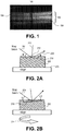
Figure 1 is an image of reflected Al Kα x-rays from a monochromator based on six individual crystals or platelets grouped on a common substrate, in accordance with an embodiment of the present invention. -
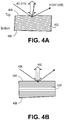
Figures 2A and 2B illustrate schematic cross-sectional views of conventional measurements made during the manufacture of an individual quartz crystal for ultimate monochromator fabrication. -
Figures 3A and 3B illustrate schematic cross-sectional views of measurements made during the manufacture of an individual quartz crystal for ultimate monochromator fabrication, in accordance with an embodiment of the present invention. -
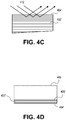
Figures 4A-4D illustrate schematic cross-sectional views of measurements made during the manufacture of an individual quartz crystal for ultimate monochromator fabrication, in accordance with an embodiment of the present invention. -
Figure 5 is an illustration representing a film measurement system having XPS detection capability and a monochromator. -
Figure 6A illustrates a schematic of a system for performing an autocollimator measurement of a surface of a crystal for use in a monochromator. -
Figure 6B illustrates a schematic of a system for performing an oblique measurement of a surface of a crystal for use in a monochromator. -
Figure 7 illustrates a block diagram of an exemplary computer system for an apparatus used during the manufacture of an individual quartz crystal for ultimate monochromator fabrication. - Methods and systems for fabricating platelets of a monochromator for X-ray photoelectron spectroscopy (XPS) are described. In the following description, numerous specific details are set forth, such as XPS system arrangements incorporating a monochromator having quartz platelets, in order to provide a thorough understanding of embodiments of the present invention.
- XPS analysis commonly employs monochromatic aluminum Kα (AlKα) X-rays, which may be generated by bombarding an aluminum anode surface with a focused electron beam. The Al-based X-rays are typically focused with a quartz crystal monochromator. XPS signals obtained from samples bombarded with such radiation are typically strong and therefore often provide very meaningful data. However, as mentioned above, in order to further improve the capabilities of XPS, advances are needed in the area of monochromator fabrication. In particular, improvements are needed in the area of quartz platelet fabrication for quartz-based monochromators.
- To provide context, performance characteristic of a monochromator fabricated from several quartz crystals, or platelets, can depend on the quality of the individual quartz crystals as well as the crystal orientation consistency of several such crystals. In the former case, monochromator quality can be compromised by localized slope errors or flaws in an individual crystal or platelet. In the latter case, monochromator quality can be compromised by platelet crystal orientation variations in the as-fabricated monochromator. In general, from platelet to platelet, the orientation is determined by the polish. Within a platelet, the orientation consistency is largely determined by the quartz quality.
- In an exemplary embodiment, individual quartz crystals or platelets are bonded to a common substrate for monochromator manufacture. Optical contact is typically performed to ensure that the bonded crystals strictly conform to the precision surface of the monochromator substrate (e.g., typically an elliptical surface). In an example, each of the crystals or platelets is thinned to approximately 60 microns to handle any associated bend stress (e.g., stress from contacting them to a curved substrate).
Figure 1 is animage 100 of reflected light from amonochromator 102 based on six individual crystals orplatelets 104 grouped on a common substrate, in accordance with an embodiment of the present invention. The individual crystals are each axis-aligned normal to the quartz surface and, as such, each crystal is individually aligned to provide each platelet of themonochromator 102. In the case that the crystals of the resulting platelets are mis-oriented, then blur from the monochromator occurs. - To aid in illustration of one or more embodiments described herein,
Figures 2A and 2B illustrate schematic cross-sectional views of conventional measurements made during the manufacture of an individual quartz crystal for ultimate monochromator fabrication. Referring toFigure 2A , crystal orientation is determined by measuring acrystal 202 with anX-ray beam 204 relative to asurface 206, e.g., relative to an uppermost surface of a stage. Areflected X-ray beam 208 subtends acrystal plane 210 within thecrystal 202 with the same angle θ to as theincoming x-ray beam 204. In such a measurement, thesurface 212 of the crystal (e.g., the orientation of thesurface 212 to the surface 206) is irrelevant. That is, normal 211 for the measurement is oriented to thecrystal plane 210. - Referring again to
Figure 2A , the complete measurement is made by first recording the angle θ of the reflected beam. Then, referring toFigure 2B , thecrystal 202 is rotated 180 degrees, e.g., by rotating 214 the stage. Once rotated, theX-ray beam 204 is again impinged on thecrystal 202 to determine an angle γ. The difference of the two angular measurements (i.e., the difference between θ and γ) provides information regarding the angle of thecrystal planes 210 of thecrystal 202 relative to the stage surface 206 (or equivalently, the bottom surface of the crystal 202). If the angles both read exactly the same, the planes are perfectly parallel to thestage surface 206. However, if the angles differ by 1°, then the planes are off 0.5°, etc. It is to be understood that the above described arrangement provides the orientation in the L-R direction. The orthogonal orientation is measured by comparing angles with the stage at 90° and 270°. Nonetheless, the above described measurement is based on the assumption that the stage rotation is perfect, which is rarely the case, particularly within an error of less than 1 arcsec level for high quality monochromator manufacturing. - In accordance with the present invention, crystal orientation is measured relative to a stage surface using an autocollimator during the above described orientation determination. In the present invention, an autocollimator is combined with a system used for measuring relative crystal plane orientation to determine the quality of a measured crystal in the preparation of the crystal for inclusion in a monochromator as a high quality platelet. The autocollimator is used to provide a reading of the surface angle of the crystal, e.g., in addition to the crystal plane angle information described above. In one such embodiment, in order to obtain high quality surface information, a reflective layer is added to the surface of the crystal. However, the reflectively layer is kept sufficiently thin to not hinder the above described X-ray measurements. In other embodiments, a reflective layer is not used.
- As a general example,
Figures 3A and 3B illustrate schematic cross-sectional views of measurements made during the manufacture of an individual quartz crystal for ultimate monochromator fabrication, in accordance with an embodiment of the present invention. Referring toFigure 3A , orientation of theplanes 310 internal to acrystal 302 is measured with anX-ray beam 304. A reflectedX-ray beam 308 subtends acrystal plane 310 within thecrystal 302 with the same angle θ to as theincoming x-ray beam 304. As described above, in such a measurement, thesurface 312 of the crystal 302 (e.g., the orientation of thesurface 312 to an underlying surface 306) does not play a role in the X-ray measurement. That is, normal 311 for the measurement is oriented to thecrystal plane 310. Additionally, referring again toFigure 3A , an autocollimator (AC)measurement 320 is made to determine an angle of a reflected beam of the AC relative to an angle of thesurface 312 as measured by the AC. - Then, referring to
Figure 3B , an underlying stage is rotated 180 degrees and the above measurements (both X-ray and AC) are repeated. As a result, information regarding an X-ray angle relative to the AC surface measurement is provided for at least two orientations. The difference between the measurements at the relative positions ofFigures 3A and 3B provides the orientation ofcrystal plane 310 relative to thesurface 312 of thecrystal 302. Essentially, then, any requirements that an underlying stage be perfect and are eliminated and now accounted for with thesurface 312 angle measurements. That is, the conventional measuring of crystal planes described in association withFigures 2A and 2B as assumed against the bottom of the crystal resting on a perfectly flat underlying stage (perfect-stage scenario) is replaced with measurement against an angle relative to thetop surface 312 of thecrystal 302. It is to be understood that, even if the AC is not perfectly aligned with an underlying stage, the measurements of crystal plane and crystal surface orientation will not be impacted since measurements are taken at more than one stage orientation. - As a more specific example,
Figures 4A-4D illustrate schematic cross-sectional views of measurements made during the manufacture of an individual quartz crystal for ultimate monochromator fabrication, in accordance with an embodiment of the present invention. Referring toFigure 4A , acrystal 402 has atop surface 404 and abottom surface 406. AnX-ray measurement 408 is made to determine crystal plane orientation internal to thecrystal 402, without influence from the orientation ofsurface 404. An autocollimator (AC)measurement 410 is also made to determine orientation of thesurface 404, e.g., relative to thebottom surface 406. As such, both AC and X-ray information (and, hence, AC information relative to X-ray information) is obtained forcrystal 402 at a first position of thecrystal 402. - In an embodiment, in order to obtain good reflection data from
surface 404 forAC measurement 410, a reflective coating (e.g., a silver coating) is first formed on thesurface 404. In one such embodiment, the reflective coating is maintained sufficiently thin to not interfere withX-ray measurement 408. It is to be understood, however, that for an opaque material, such as InSb, a reflective coating may not be necessary. - In an embodiment, referring again to
Figure 4A , four such measurements are taken at 90 degree intervals in order to remove the delta between the X-ray and AC coordinate system. For example, the absolute delta in x-direction is the delta X-ray minus AC for 0° and 180°. For y-direction, the absolute delta X-ray minus AC at 90° and 270°. More generally, in the present invention, measuring with X-ray and AC involves performing first and second X-ray reflection measurements at approximately 180 degrees to one another. In one such embodiment, the measuring further involves performing third and fourth X-ray reflection measurements at approximately 180 degrees to one another, and orthogonal to the first and second X-ray reflection measurements. In an embodiment, measuring the surface angle of thetop surface 404 of thecrystal 402 enables accommodating for rocking of thecrystal 402 on a stage (e.g., the stage shown inFigures 3A and 3B ) during the measuring of the orientation of the internal crystal planes of the crystal. - Thus, in the present invention, referring in general to
Figure 4A in association withFigures 3A and 3B , a method of fabricating a platelet for a monochromator involves placing acrystal 402 on a stage of an X-ray measuring apparatus. Thecrystal 402 has atop surface 402 with a reflective layer disposed thereon. An orientation of a crystal plane of thecrystal 402 is measured byX-ray reflection 408, where the crystal plane is beneath the top surface of thecrystal 402 and has a primary axis. The method also involves measuring a surface angle of the top surface of the crystal by measuring a light beam reflected from the reflective layer disposed on the top surface of thecrystal 402, e.g., by anAC measurement 410. In one such embodiment, the surface angle of the top surface of thecrystal 402 is measured while measuring the orientation of the crystal plane by X-ray reflection. The measurements are made at several different rotational positions of a stage or other underlying surface. In the present invention, the measurements enable determination of an angle between thetop surface 404 and the primary axis of the crystal plane of thecrystal 402. In a specific such embodiment, if the angle between the top surface and the primary axis of the crystal plane is approximately normal or at unity, the reflective layer is removed from the crystal to provide a platelet for monochromator fabrication. If, however, the angle between the top surface and the primary axis of the crystal plane is not approximately normal or at unity, polishing of the crystal may be needed, as described below. - Referring to
Figure 4B , thecrystal 402 ofFigure 4A is adjusted by polishingtop surface 404 until theX-ray measurement 408 and theAC measurement 410 agree to unity. This operation provides a new top surface 404' for an adjusted crystal 402'. The process may involve several iterations of the measurements described in association withFigure 4A , as depicted inFigure 4B . In an embodiment, since the polishing is performed at thetop surface 404, a reflective coating layer may need to be redeposited for each iteration. At this stage in the fabrication, in an embodiment, thebottom surface 406 may not be parallel to the polished top surface 404', as is depicted. - Thus, in the present invention, the angle between the top surface and the primary axis of the crystal plane is not approximately normal or at unity as described in association with
Figure 4A , at least a portion of thetop surface 404 of thecrystal 402 is removed to provide a modified crystal 402' having a second top surface 404'. In one such embodiment, a second reflective layer is formed on the second top surface 404' of the modified crystal 402'. The measurements described in association withFigure 4A are then repeated. The process may be reiterated until the angle between the top surface and the primary axis of the crystal plane is approximately normal or at unity. - Referring again to
Figures 4A and 4B , asurface 404 measurement is performed by measuring a light beam reflected from a reflective layer by impinging radiation from a light source of an autocollimator on the reflective layer. In one such embodiment, the impinging radiation is aligned normal to the stage of an X-ray measuring apparatus. In a specific such embodiment, visible light is emitted from the light source of the collimator. - Referring to
Figure 4C , in an embodiment, topography of the new surface 404' is measured by atopographical measurement 412. For example, although the polished surface 404' may provide a global surface where an X-ray measurement and an AC measurement of the surface 404' agree to unity, smaller topographical imperfections may be removed at this point to ensure global uniformity. It is to be understood that there may be little that can be done to fix or remove imperfections within a single crystal. Nonetheless, in one embodiment, it is still valuable to check uniformity across the crystal prior to contacting the crystal to a substrate for monochromator fabrication, e.g., in the case that the crystal is not suitable for use. - Referring to
Figure 4D , the adjusted crystal 402' having the new top surface 404' is polished from thebottom surface 406 to provide new bottom surface 406' of a thinned, and properly oriented, crystal orplatelet 402". In an embodiment, the adjusted crystal 402' is flipped and is thinned from thebottom surface 406 and made parallel to the top surface 404'. In one such embodiment, the thinning is ensured to be parallel by using interferometric feedback during the thinning. The crystal orplatelet 402" thus has internal planes that are parallel with the surfaces 404' and 406'. - Thus, in an embodiment, a method of fabricating a platelet for a monochromator involves thinning the modified crystal 402' from a
bottom surface 406 of the modified crystal 402' opposite the second top surface 404' to render a new bottom surface 406' parallel with the second top surface 404' based on interferometric feedback. In an embodiment, then, both the top and bottom surface of a crystal are modified. In another embodiment, however, only the bottom surface is modified. For example, in one such embodiment, in the case the angle between the top surface and the primary axis of the crystal plane is approximately normal or at unity at the initial measurements ofFigure 4A , operations described in association withFigure 4B are omitted and prior to fabricating the monochromator, only the bottom surface of the crystal is thinned to render the bottom surface parallel with the top surface. The thinning may be based on interferometric feedback. - Outside the scope of the present invention, an XPS system includes a monochromator having platelets fabricated by an approaches described herein. For example,
Figure 5 is an illustration representing a film measurement system having XPS detection capability. It is to be understood that the XPS system described below is one exemplary system where a monochromator described herein may be used. Other systems may equally benefit, or even benefit to a greater extent, from one or more embodiments described herein. For example, an XRF measurement system may include a like monochromator. And, in some cases, the XRF can be more sensitive to monochromator blur than the XPS measurement system described below. - Referring to
Figure 5 , afilm measurement system 500 includes an XPS generation and detection system housed in achamber 501 coupled with acomputing system 518. The XPS generation and detection system includes anelectron beam source 502 provided for generating anelectron beam 504.Electron beam 504 is used to generate anX-ray beam 508 by bombarding ananode 506. Amonochromator 509 is provided for focusing amonochromatized X-ray beam 510 fromX-ray beam 508. Asample holder 511 may be used to position asample 599 in a pathway ofmonochromatized X-ray beam 510. AnXPS detector 514 is provided for collecting anXPS signal 512 generated by bombardingsample 599 withmonochromatized X-ray beam 510.Computing system 518 may include auser interface 520 coupled with acomputing portion 522 having amemory portion 524. - Additionally, a
flux detector 516 may be provided for determining an estimated flux ofmonochromatized X-ray beam 510. In one such system,flux detector 516 is positioned atsample holder 511, as depicted inFigure 5 . In a system Flux detector 521 is used to provide a proxy X-ray flux measurement forFlux detector 520 for estimated flux ofmonochromatized X-ray beam 510. By positioning flux detector 521 at near the monochromator to intersect a small portion of the primary X-ray flux above thesample 511, the primary X-ray flux can be monitored while themonochromatized X-ray beam 510 meetssample holder 511, as depicted inFigure 5 . - In the present invention, and in order to address one or more of the above described issues with
monochromator 509 fabrication, an auto-collimator is used in the manufacture of individual platelets, e.g., in the manufacture of quartz platelets. In one such embodiment, themonochromator 509 ofFigure 5 is fabricated from several such platelets. In a particular embodiment, themonochromator 509 has a total crystal surface area of approximately 140mm x 48mm, and a total blur of the monochromator is less than approximately 5 microns. In one embodiment, absolute alignment of the crystals or platelets to surface normal is less than approximately 50µrad (e.g., approximately 1.5microns of blur). In one embodiment, consistency of the planes in the quartz platelets is less than approximately 5µrad (e.g., 2 microns of blur). In a particular embodiment, the above blur-related values are suitable for a monochromator having a focal length of the optic or approximately 200mm. - Outside the scope of the invention, an XPS measurement may be made upon introduction of a sample into the
XPS system 500. The sample is bombarded with a monochromatized (by monochromator 500) X-ray beam. In response to bombardment by the X-ray beam, an XPS signal (composed of photo-electrons) is emitted from the sample and collected in a detector. The XPS signal is correlated with the atomic dose of a particular atomic species in the sample. The atomic dose is correlated with a sample property such as, but not limited to, the thickness of a film in the sample, the depth to which the particular atomic species is incorporated into the sample or a concentration ratio of several atomic species in the sample. - Examples outside the scope of the present invention may not be limited to the use of autocollimator-based measurements. As a reference point, however,
Figure 6A illustrates a schematic of asystem 600 for performing an autocollimator measurement of a surface of a crystal for use in a monochromator, in accordance with an embodiment of the present invention. Referring toFigure 6A , anautocollimator 602 is used to measure a surface angle of asample 604. As is seen inFigure 6A , the measurement is typically performed essentially, if not perfectly, normal to the measured surface of thesample 604. A convenience of using an autocollimator may be the ready commercial availability of such a measuring apparatus. One of ordinary skill in the art will appreciate that, in optics, a "collimator" refers to a lens or set of lenses/mirrors that converts a diverging beam into a parallel beam. In other instances, the term may be used to refer to a set of lenses that shrink or expand an existing collimated beam into another collimated beam of a different diameter. In an embodiment, the term, "autocollimator" refers to a specific instrument that is used to measure surface angles. - Outside the scope of the present invention, in place of an autocollimator, systems based on oblique angle surface measurements may be used. For example,
Figure 6B illustrates a schematic of a system for performing an oblique measurement of a surface of a crystal for use in a monochromator. Referring toFigure 6B , alaser 650 is used at an angle other than normal to introduce light on a surface which is reflected and collected at a position-sensitive detector 652. That is, if surface measurement apparatus other than an autocollimator is used, non-normal angle measurements may be made to determine surface angles for a sample. Thus, more generally, in addition to autocollimator measurements, other optical techniques may be used. In essence, any suitable approach may be used where an optical technique provides information regarding surface orientation, while the X-ray measurements provide information regarding crystal plane orientation. - Outside the scope of the present invention, an apparatus for providing measurements during a method of fabricating a platelet of a monochromator for X-ray photoelectron spectroscopy includes a stage having a location for placing a crystal thereon. An X-ray source and corresponding detector for performing X-ray reflection measurements of a crystal plane of the crystal is also included. An autocollimator is provided with a light source for impinging radiation on the crystal, along with a corresponding detector for measuring a light beam reflected from the crystal. In one such apparatus, the autocollimator is aligned normal to the stage. In one such apparatus, the light source is a visible light source. In one such apparatus, the above arrangement enables use of an imperfect stage. The autocollimator measurements can be used to confirm that no crystal tipping occurred during X-ray measurement, instead of relying on or making assumptions based on an idealized stage.
- The above described crystal measuring apparatus, or similar apparatus, further includes a computer system coupled to the corresponding detector of the X-ray source and the corresponding detector of the autocollimator. Thus, examples outside the scope of the present invention may be provided as a computer program product, or software, that may include a machine-readable medium having stored thereon instructions, which may be used to program a computer system (or other electronic devices) to perform a process according to the present invention. A machine-readable medium includes any mechanism for storing or transmitting information in a form readable by a machine (e.g., a computer). For example, a machine-readable (e.g., computer-readable) medium includes a machine (e.g., a computer) readable storage medium (e.g., read only memory ("ROM"), random access memory ("RAM"), magnetic disk storage media, optical storage media, flash memory devices, etc.), a machine (e.g., computer) readable transmission medium (electrical, optical, acoustical or other form of propagated signals (e.g., infrared signals, digital signals, etc.)), etc.
-
Figure 7 illustrates a diagrammatic representation of a machine in the exemplary form of acomputer system 700 within which a set of instructions, for causing the machine to perform any one or more of the methodologies discussed herein, may be executed. The machine may be connected (e.g., networked) to other machines in a Local Area Network (LAN), an intranet, an extranet, or the Internet. The machine may operate in the capacity of a server or a client machine in a client-server network environment, or as a peer machine in a peer-to-peer (or distributed) network environment. The machine may be a personal computer (PC), a tablet PC, a set-top box (STB), a Personal Digital Assistant (PDA), a cellular telephone, a web appliance, a server, a network router, switch or bridge, or any machine capable of executing a set of instructions (sequential or otherwise) that specify actions to be taken by that machine. Further, while only a single machine is illustrated, the term "machine" shall also be taken to include any collection of machines (e.g., computers) that individually or jointly execute a set (or multiple sets) of instructions to perform any one or more of the methodologies discussed herein. For example, a machine is configured to execute one or more sets of instruction for fabricating a platelet for a monochromator. - The
exemplary computer system 700 includes aprocessor 702, a main memory 704 (e.g., read-only memory (ROM), flash memory, dynamic random access memory (DRAM) such as synchronous DRAM (SDRAM) or Rambus DRAM (RDRAM), etc.), a static memory 706 (e.g., flash memory, static random access memory (SRAM), etc.), and a secondary memory 718 (e.g., a data storage device), which communicate with each other via abus 730. -
Processor 702 represents one or more general-purpose processing devices such as a microprocessor, central processing unit, or the like. More particularly, theprocessor 702 may be a complex instruction set computing (CISC) microprocessor, reduced instruction set computing (RISC) microprocessor, very long instruction word (VLIW) microprocessor, processor implementing other instruction sets, or processors implementing a combination of instruction sets.Processor 702 may also be one or more special-purpose processing devices such as an application specific integrated circuit (ASIC), a field programmable gate array (FPGA), a digital signal processor (DSP), network processor, or the like.Processor 702 is configured to execute theprocessing logic 726 for performing the operations discussed herein. - The
computer system 700 may further include anetwork interface device 708. Thecomputer system 700 also may include a video display unit 710 (e.g., a liquid crystal display (LCD) or a cathode ray tube (CRT)), an alphanumeric input device 712 (e.g., a keyboard), a cursor control device 714 (e.g., a mouse), and a signal generation device 716 (e.g., a speaker). - The
secondary memory 718 may include a machine-accessible storage medium (or more specifically a computer-readable storage medium) 731 on which is stored one or more sets of instructions (e.g., software 722) embodying any one or more of the methodologies or functions described herein. Thesoftware 722 may also reside, completely or at least partially, within themain memory 704 and/or within theprocessor 702 during execution thereof by thecomputer system 700, themain memory 704 and theprocessor 702 also constituting machine-readable storage media. Thesoftware 722 may further be transmitted or received over anetwork 720 via thenetwork interface device 708. - While the machine-
accessible storage medium 731 is shown to be a single medium, the term "machine-readable storage medium" should be taken to include a single medium or multiple media (e.g., a centralized or distributed database, and/or associated caches and servers) that store the one or more sets of instructions. The term "machine-readable storage medium" shall also be taken to include any medium that is capable of storing or encoding a set of instructions for execution by the machine and that cause the machine to perform any one or more of the methodologies previously described. The term "machine-readable storage medium" shall accordingly be taken to include, but not be limited to, solid-state memories, and optical and magnetic media. - Outside the scope of the present invention, a computer system has a non-transitory machine-accessible storage medium having instructions stored thereon which cause a data processing system to perform a method of fabricating a platelet of a monochromator for X-ray photoelectron spectroscopy. The method involves measuring, by X-ray reflection, an orientation of a crystal plane of the crystal, the crystal plane beneath a top surface of the crystal and having a primary axis. The method also involves, measuring a surface angle of the top surface of the crystal by measuring a light beam reflected from a reflective layer disposed on the top surface of the crystal. The surface angle of the top surface of the crystal is measured while measuring the orientation of the crystal plane by X-ray reflection.
- Thus, methods and systems for fabricating platelets of a monochromator for X-ray photoelectron spectroscopy (XPS) have been described.
Claims (10)
- A method of fabricating a platelet of a monochromator (509) for X-ray photoelectron spectroscopy, the method comprising:placing a crystal (202, 302, 402) on a stage of an X-ray measuring apparatus, the crystal having a top surface (206, 306, 406); measuring, by X-ray reflection, an orientation of a crystal plane (210, 3010, 410) of the crystal, the crystal plane beneath the top surface of the crystal and having a primary axis;measuring, using an autocollimator, a surface angle of the top surface (212, 312) of the crystal by measuring a light beam reflected from the top surface of the crystal; wherein measuring the orientation of the crystal plane of the crystal and measuring the surface angle of the top surface of the crystal comprises performing first and second X-ray reflection measurements and first and second autocollimator measurements at approximately 180 degrees to one another;determining an angle between the top surface and the primary axis of the crystal plane of the crystal;if the angle between the top surface and the primary axis of the crystal plane of the crystal is approximately normal, fabricating a monochromator comprising the platelet; andif the angle between the top surface and the primary axis of the crystal plane of the crystal is non-normal, removing at least a portion of the top surface (404) of the crystal (402) to provide a modified crystal (402') having a second top surface (404'); measuring, by X-ray reflection, an orientation of a crystal plane of the modified crystal, the crystal plane beneath the second top surface of the modified crystal; and, while measuring the orientation of the crystal plane by X-ray reflection, measuring a surface angle of the second top surface of the modified crystal by measuring a light beam reflected from the second top surface of the modified crystal; and determining an angle between the second top surface and the crystal plane of the modified crystal.
- The method of claim 1, wherein a reflective layer is disposed on the top surface of the crystal (202, 302, 402), and wherein measuring the surface angle of the top surface of the crystal comprises measuring the light bean reflected from the reflective layer.
- The method of claim 1, further comprising: prior to fabricating the monochromator (509), thinning a bottom surface (406) of the crystal (402) to render the bottom surface parallel with the top surface based on interferometric feedback.
- The method of claim 1, further comprising: thinning, from a bottom surface (406) of the modified crystal (402') opposite the second top surface (406'), the modified crystal to render the bottom surface parallel with the second top surface based on interferometric feedback.
- The method of claim 1, wherein the impinging radiation from the light source of the autocollimator comprises aligning the radiation normal to the stage of the X-ray measuring apparatus.
- The method of claim 1, wherein impinging radiation from the light source of the autocollimator comprises impinging visible light from the light source of the autocollimator.
- The method according to any one of the preceding claims wherein measuring the light beam reflected from the top surface comprises impinging radiation from a light source at an angle oblique to the stage of the X-ray measuring apparatus.
- The method of according to any one of the preceding claims wherein placing the crystal on the stage of the X-ray measuring apparatus comprises using an imperfect stage.
- The method according to any one of the preceding claims wherein measuring the surface angle of the top surface of the crystal comprises accommodating for rocking of the crystal on the stage during the measuring of the orientation of the crystal plane of the crystal.
- The method of claim 1, wherein measuring the orientation of the crystal plane of the crystal further comprises performing third and fourth X-ray reflection measurements at approximately 180 degrees to one another, and orthogonal to the first and second X-ray reflection measurements.
Applications Claiming Priority (2)
| Application Number | Priority Date | Filing Date | Title |
|---|---|---|---|
| US13/975,035 US9297771B2 (en) | 2013-08-23 | 2013-08-23 | Methods and systems for fabricating platelets of a monochromator for X-ray photoelectron spectroscopy |
| PCT/US2014/051688 WO2015026824A1 (en) | 2013-08-23 | 2014-08-19 | Methods and systems for fabricating platelets of a monochromator for x-ray photoelectron spectroscopy |
Publications (3)
| Publication Number | Publication Date |
|---|---|
| EP3036533A1 EP3036533A1 (en) | 2016-06-29 |
| EP3036533A4 EP3036533A4 (en) | 2017-03-15 |
| EP3036533B1 true EP3036533B1 (en) | 2019-12-04 |
Family
ID=52479054
Family Applications (1)
| Application Number | Title | Priority Date | Filing Date |
|---|---|---|---|
| EP14837703.9A Active EP3036533B1 (en) | 2013-08-23 | 2014-08-19 | Methods for fabricating platelets of a monochromator for x-ray photoelectron spectroscopy |
Country Status (3)
| Country | Link |
|---|---|
| US (1) | US9297771B2 (en) |
| EP (1) | EP3036533B1 (en) |
| WO (1) | WO2015026824A1 (en) |
Families Citing this family (2)
| Publication number | Priority date | Publication date | Assignee | Title |
|---|---|---|---|---|
| CN113655515B (en) * | 2021-09-06 | 2025-01-14 | 中国原子能科学研究院 | Performance test method of focusing neutron monochromator |
| TW202546859A (en) * | 2024-01-09 | 2025-12-01 | 美商諾威量測設備公司 | Soft x-ray monochromator |
Citations (1)
| Publication number | Priority date | Publication date | Assignee | Title |
|---|---|---|---|---|
| US20120140889A1 (en) * | 2010-12-02 | 2012-06-07 | Jordan Valley Semiconductors Ltd. | Fast measurement of x-ray diffraction from tilted layers |
Family Cites Families (9)
| Publication number | Priority date | Publication date | Assignee | Title |
|---|---|---|---|---|
| US3772522A (en) * | 1972-02-17 | 1973-11-13 | Hewlett Packard Co | Crystal monochromator and method of fabricating a diffraction crystal employed therein |
| US3927319A (en) | 1974-06-28 | 1975-12-16 | Univ Southern California | Crystal for X-ray crystal spectrometer |
| US4599741A (en) | 1983-11-04 | 1986-07-08 | USC--Dept. of Materials Science | System for local X-ray excitation by monochromatic X-rays |
| US5315113A (en) | 1992-09-29 | 1994-05-24 | The Perkin-Elmer Corporation | Scanning and high resolution x-ray photoelectron spectroscopy and imaging |
| US5768335A (en) * | 1997-02-10 | 1998-06-16 | Lucent Technologies Inc. | Apparatus and method for measuring the orientation of a single crystal surface |
| US6055293A (en) * | 1998-06-30 | 2000-04-25 | Seh America, Inc. | Method for identifying desired features in a crystal |
| US6825467B2 (en) * | 2002-06-25 | 2004-11-30 | Agere Systems, Inc. | Apparatus for scanning a crystalline sample and associated methods |
| GB2442485B (en) | 2006-10-03 | 2008-12-10 | Thermo Electron Corp | X-ray photoelectron spectroscopy analysis system for surface analysis and method therefor |
| US9240254B2 (en) | 2011-09-27 | 2016-01-19 | Revera, Incorporated | System and method for characterizing a film by X-ray photoelectron and low-energy X-ray fluorescence spectroscopy |
-
2013
- 2013-08-23 US US13/975,035 patent/US9297771B2/en active Active
-
2014
- 2014-08-19 WO PCT/US2014/051688 patent/WO2015026824A1/en not_active Ceased
- 2014-08-19 EP EP14837703.9A patent/EP3036533B1/en active Active
Patent Citations (1)
| Publication number | Priority date | Publication date | Assignee | Title |
|---|---|---|---|---|
| US20120140889A1 (en) * | 2010-12-02 | 2012-06-07 | Jordan Valley Semiconductors Ltd. | Fast measurement of x-ray diffraction from tilted layers |
Non-Patent Citations (1)
| Title |
|---|
| LIM JUN ET AL: "Measurement of the parallelism error of a double crystal monochromator by the pencil beam interferometer", REVIEW OF SCIENTIFIC INSTRUMENTS, AIP, MELVILLE, NY, US, vol. 76, no. 6, 1 June 2005 (2005-06-01), pages 65109 - 065109, XP012079524, ISSN: 0034-6748, DOI: 10.1063/1.1928188 * |
Also Published As
| Publication number | Publication date |
|---|---|
| WO2015026824A1 (en) | 2015-02-26 |
| EP3036533A1 (en) | 2016-06-29 |
| US9297771B2 (en) | 2016-03-29 |
| EP3036533A4 (en) | 2017-03-15 |
| US20150052723A1 (en) | 2015-02-26 |
Similar Documents
| Publication | Publication Date | Title |
|---|---|---|
| US10859519B2 (en) | Methods and systems for measuring periodic structures using multi-angle x-ray reflectance scatterometry (XRS) | |
| US20130021610A1 (en) | Method and apparatus for real-time determination of spherical and non-spherical curvature of a surface | |
| TW201346213A (en) | Calibration of an optical metrology system for critical dimension application matching | |
| US8867041B2 (en) | Optical vacuum ultra-violet wavelength nanoimprint metrology | |
| TW201229503A (en) | Fast measurement of X-ray diffraction from tilted layers | |
| CN107917665B (en) | Method and apparatus for determining the position of a light spot | |
| US9297771B2 (en) | Methods and systems for fabricating platelets of a monochromator for X-ray photoelectron spectroscopy | |
| TW202424475A (en) | Methods and systems for x-ray scatterometry measurements employing a machine learning based electromagnetic response model | |
| Peña Arellano et al. | Interferometric measurement of angular motion | |
| Shimizu et al. | A PD-edge method associated with the laser autocollimation for measurement of a focused laser beam diameter | |
| JP4764208B2 (en) | Method for evaluating the orientation of polycrystalline materials | |
| Henriksen et al. | Qualification and performance of the Low-Energy X-ray Reflectometer (LEXR) | |
| CN118330009B (en) | Method and system for measuring concentration of substance in wafer film | |
| Santagati et al. | Development and characterization of a high-sensitivity and high-throughput in-house multimodal TXRF/GIXRF mobile spectrometer | |
| Yamazaki et al. | Neutron Focusing by a Kirkpatrick–Baez Type Super-Mirror | |
| Su et al. | Development and instrumentation of an integrated three–dimensional optical testing system for application in integrated circuit packaging | |
| Fitch et al. | Analysis of iridium reflectance measurements for AXAF witness mirrors from 2 to 12 keV |
Legal Events
| Date | Code | Title | Description |
|---|---|---|---|
| PUAI | Public reference made under article 153(3) epc to a published international application that has entered the european phase |
Free format text: ORIGINAL CODE: 0009012 |
|
| 17P | Request for examination filed |
Effective date: 20160215 |
|
| AK | Designated contracting states |
Kind code of ref document: A1 Designated state(s): AL AT BE BG CH CY CZ DE DK EE ES FI FR GB GR HR HU IE IS IT LI LT LU LV MC MK MT NL NO PL PT RO RS SE SI SK SM TR |
|
| AX | Request for extension of the european patent |
Extension state: BA ME |
|
| DAX | Request for extension of the european patent (deleted) | ||
| A4 | Supplementary search report drawn up and despatched |
Effective date: 20170210 |
|
| RIC1 | Information provided on ipc code assigned before grant |
Ipc: H01J 49/48 20060101ALI20170206BHEP Ipc: G01N 23/227 20060101ALI20170206BHEP Ipc: H01J 37/256 20060101ALI20170206BHEP Ipc: G01N 23/22 20060101AFI20170206BHEP |
|
| RAP1 | Party data changed (applicant data changed or rights of an application transferred) |
Owner name: NOVA MEASURING INSTRUMENTS, INC. |
|
| GRAP | Despatch of communication of intention to grant a patent |
Free format text: ORIGINAL CODE: EPIDOSNIGR1 |
|
| STAA | Information on the status of an ep patent application or granted ep patent |
Free format text: STATUS: GRANT OF PATENT IS INTENDED |
|
| INTG | Intention to grant announced |
Effective date: 20190711 |
|
| GRAS | Grant fee paid |
Free format text: ORIGINAL CODE: EPIDOSNIGR3 |
|
| GRAA | (expected) grant |
Free format text: ORIGINAL CODE: 0009210 |
|
| STAA | Information on the status of an ep patent application or granted ep patent |
Free format text: STATUS: THE PATENT HAS BEEN GRANTED |
|
| AK | Designated contracting states |
Kind code of ref document: B1 Designated state(s): AL AT BE BG CH CY CZ DE DK EE ES FI FR GB GR HR HU IE IS IT LI LT LU LV MC MK MT NL NO PL PT RO RS SE SI SK SM TR |
|
| RAP1 | Party data changed (applicant data changed or rights of an application transferred) |
Owner name: NOVA MEASURING INSTRUMENTS, INC. |
|
| REG | Reference to a national code |
Ref country code: GB Ref legal event code: FG4D |
|
| REG | Reference to a national code |
Ref country code: CH Ref legal event code: EP |
|
| REG | Reference to a national code |
Ref country code: AT Ref legal event code: REF Ref document number: 1210006 Country of ref document: AT Kind code of ref document: T Effective date: 20191215 |
|
| REG | Reference to a national code |
Ref country code: DE Ref legal event code: R096 Ref document number: 602014057964 Country of ref document: DE |
|
| REG | Reference to a national code |
Ref country code: IE Ref legal event code: FG4D |
|
| REG | Reference to a national code |
Ref country code: NL Ref legal event code: MP Effective date: 20191204 |
|
| REG | Reference to a national code |
Ref country code: LT Ref legal event code: MG4D |
|
| PG25 | Lapsed in a contracting state [announced via postgrant information from national office to epo] |
Ref country code: LT Free format text: LAPSE BECAUSE OF FAILURE TO SUBMIT A TRANSLATION OF THE DESCRIPTION OR TO PAY THE FEE WITHIN THE PRESCRIBED TIME-LIMIT Effective date: 20191204 Ref country code: GR Free format text: LAPSE BECAUSE OF FAILURE TO SUBMIT A TRANSLATION OF THE DESCRIPTION OR TO PAY THE FEE WITHIN THE PRESCRIBED TIME-LIMIT Effective date: 20200305 Ref country code: FI Free format text: LAPSE BECAUSE OF FAILURE TO SUBMIT A TRANSLATION OF THE DESCRIPTION OR TO PAY THE FEE WITHIN THE PRESCRIBED TIME-LIMIT Effective date: 20191204 Ref country code: BG Free format text: LAPSE BECAUSE OF FAILURE TO SUBMIT A TRANSLATION OF THE DESCRIPTION OR TO PAY THE FEE WITHIN THE PRESCRIBED TIME-LIMIT Effective date: 20200304 Ref country code: SE Free format text: LAPSE BECAUSE OF FAILURE TO SUBMIT A TRANSLATION OF THE DESCRIPTION OR TO PAY THE FEE WITHIN THE PRESCRIBED TIME-LIMIT Effective date: 20191204 Ref country code: NO Free format text: LAPSE BECAUSE OF FAILURE TO SUBMIT A TRANSLATION OF THE DESCRIPTION OR TO PAY THE FEE WITHIN THE PRESCRIBED TIME-LIMIT Effective date: 20200304 Ref country code: LV Free format text: LAPSE BECAUSE OF FAILURE TO SUBMIT A TRANSLATION OF THE DESCRIPTION OR TO PAY THE FEE WITHIN THE PRESCRIBED TIME-LIMIT Effective date: 20191204 |
|
| PG25 | Lapsed in a contracting state [announced via postgrant information from national office to epo] |
Ref country code: HR Free format text: LAPSE BECAUSE OF FAILURE TO SUBMIT A TRANSLATION OF THE DESCRIPTION OR TO PAY THE FEE WITHIN THE PRESCRIBED TIME-LIMIT Effective date: 20191204 Ref country code: RS Free format text: LAPSE BECAUSE OF FAILURE TO SUBMIT A TRANSLATION OF THE DESCRIPTION OR TO PAY THE FEE WITHIN THE PRESCRIBED TIME-LIMIT Effective date: 20191204 |
|
| PG25 | Lapsed in a contracting state [announced via postgrant information from national office to epo] |
Ref country code: AL Free format text: LAPSE BECAUSE OF FAILURE TO SUBMIT A TRANSLATION OF THE DESCRIPTION OR TO PAY THE FEE WITHIN THE PRESCRIBED TIME-LIMIT Effective date: 20191204 |
|
| PG25 | Lapsed in a contracting state [announced via postgrant information from national office to epo] |
Ref country code: PT Free format text: LAPSE BECAUSE OF FAILURE TO SUBMIT A TRANSLATION OF THE DESCRIPTION OR TO PAY THE FEE WITHIN THE PRESCRIBED TIME-LIMIT Effective date: 20200429 Ref country code: ES Free format text: LAPSE BECAUSE OF FAILURE TO SUBMIT A TRANSLATION OF THE DESCRIPTION OR TO PAY THE FEE WITHIN THE PRESCRIBED TIME-LIMIT Effective date: 20191204 Ref country code: RO Free format text: LAPSE BECAUSE OF FAILURE TO SUBMIT A TRANSLATION OF THE DESCRIPTION OR TO PAY THE FEE WITHIN THE PRESCRIBED TIME-LIMIT Effective date: 20191204 Ref country code: CZ Free format text: LAPSE BECAUSE OF FAILURE TO SUBMIT A TRANSLATION OF THE DESCRIPTION OR TO PAY THE FEE WITHIN THE PRESCRIBED TIME-LIMIT Effective date: 20191204 Ref country code: EE Free format text: LAPSE BECAUSE OF FAILURE TO SUBMIT A TRANSLATION OF THE DESCRIPTION OR TO PAY THE FEE WITHIN THE PRESCRIBED TIME-LIMIT Effective date: 20191204 Ref country code: NL Free format text: LAPSE BECAUSE OF FAILURE TO SUBMIT A TRANSLATION OF THE DESCRIPTION OR TO PAY THE FEE WITHIN THE PRESCRIBED TIME-LIMIT Effective date: 20191204 |
|
| PG25 | Lapsed in a contracting state [announced via postgrant information from national office to epo] |
Ref country code: SM Free format text: LAPSE BECAUSE OF FAILURE TO SUBMIT A TRANSLATION OF THE DESCRIPTION OR TO PAY THE FEE WITHIN THE PRESCRIBED TIME-LIMIT Effective date: 20191204 Ref country code: SK Free format text: LAPSE BECAUSE OF FAILURE TO SUBMIT A TRANSLATION OF THE DESCRIPTION OR TO PAY THE FEE WITHIN THE PRESCRIBED TIME-LIMIT Effective date: 20191204 Ref country code: IS Free format text: LAPSE BECAUSE OF FAILURE TO SUBMIT A TRANSLATION OF THE DESCRIPTION OR TO PAY THE FEE WITHIN THE PRESCRIBED TIME-LIMIT Effective date: 20200404 |
|
| REG | Reference to a national code |
Ref country code: DE Ref legal event code: R097 Ref document number: 602014057964 Country of ref document: DE |
|
| REG | Reference to a national code |
Ref country code: AT Ref legal event code: MK05 Ref document number: 1210006 Country of ref document: AT Kind code of ref document: T Effective date: 20191204 |
|
| PLBE | No opposition filed within time limit |
Free format text: ORIGINAL CODE: 0009261 |
|
| STAA | Information on the status of an ep patent application or granted ep patent |
Free format text: STATUS: NO OPPOSITION FILED WITHIN TIME LIMIT |
|
| PG25 | Lapsed in a contracting state [announced via postgrant information from national office to epo] |
Ref country code: DK Free format text: LAPSE BECAUSE OF FAILURE TO SUBMIT A TRANSLATION OF THE DESCRIPTION OR TO PAY THE FEE WITHIN THE PRESCRIBED TIME-LIMIT Effective date: 20191204 |
|
| 26N | No opposition filed |
Effective date: 20200907 |
|
| PG25 | Lapsed in a contracting state [announced via postgrant information from national office to epo] |
Ref country code: AT Free format text: LAPSE BECAUSE OF FAILURE TO SUBMIT A TRANSLATION OF THE DESCRIPTION OR TO PAY THE FEE WITHIN THE PRESCRIBED TIME-LIMIT Effective date: 20191204 Ref country code: PL Free format text: LAPSE BECAUSE OF FAILURE TO SUBMIT A TRANSLATION OF THE DESCRIPTION OR TO PAY THE FEE WITHIN THE PRESCRIBED TIME-LIMIT Effective date: 20191204 Ref country code: SI Free format text: LAPSE BECAUSE OF FAILURE TO SUBMIT A TRANSLATION OF THE DESCRIPTION OR TO PAY THE FEE WITHIN THE PRESCRIBED TIME-LIMIT Effective date: 20191204 |
|
| PG25 | Lapsed in a contracting state [announced via postgrant information from national office to epo] |
Ref country code: IT Free format text: LAPSE BECAUSE OF FAILURE TO SUBMIT A TRANSLATION OF THE DESCRIPTION OR TO PAY THE FEE WITHIN THE PRESCRIBED TIME-LIMIT Effective date: 20191204 |
|
| PG25 | Lapsed in a contracting state [announced via postgrant information from national office to epo] |
Ref country code: MC Free format text: LAPSE BECAUSE OF FAILURE TO SUBMIT A TRANSLATION OF THE DESCRIPTION OR TO PAY THE FEE WITHIN THE PRESCRIBED TIME-LIMIT Effective date: 20191204 |
|
| REG | Reference to a national code |
Ref country code: CH Ref legal event code: PL |
|
| PG25 | Lapsed in a contracting state [announced via postgrant information from national office to epo] |
Ref country code: LI Free format text: LAPSE BECAUSE OF NON-PAYMENT OF DUE FEES Effective date: 20200831 Ref country code: LU Free format text: LAPSE BECAUSE OF NON-PAYMENT OF DUE FEES Effective date: 20200819 Ref country code: CH Free format text: LAPSE BECAUSE OF NON-PAYMENT OF DUE FEES Effective date: 20200831 |
|
| REG | Reference to a national code |
Ref country code: BE Ref legal event code: MM Effective date: 20200831 |
|
| PG25 | Lapsed in a contracting state [announced via postgrant information from national office to epo] |
Ref country code: IE Free format text: LAPSE BECAUSE OF NON-PAYMENT OF DUE FEES Effective date: 20200819 Ref country code: BE Free format text: LAPSE BECAUSE OF NON-PAYMENT OF DUE FEES Effective date: 20200831 |
|
| PG25 | Lapsed in a contracting state [announced via postgrant information from national office to epo] |
Ref country code: TR Free format text: LAPSE BECAUSE OF FAILURE TO SUBMIT A TRANSLATION OF THE DESCRIPTION OR TO PAY THE FEE WITHIN THE PRESCRIBED TIME-LIMIT Effective date: 20191204 Ref country code: MT Free format text: LAPSE BECAUSE OF FAILURE TO SUBMIT A TRANSLATION OF THE DESCRIPTION OR TO PAY THE FEE WITHIN THE PRESCRIBED TIME-LIMIT Effective date: 20191204 Ref country code: CY Free format text: LAPSE BECAUSE OF FAILURE TO SUBMIT A TRANSLATION OF THE DESCRIPTION OR TO PAY THE FEE WITHIN THE PRESCRIBED TIME-LIMIT Effective date: 20191204 |
|
| PG25 | Lapsed in a contracting state [announced via postgrant information from national office to epo] |
Ref country code: MK Free format text: LAPSE BECAUSE OF FAILURE TO SUBMIT A TRANSLATION OF THE DESCRIPTION OR TO PAY THE FEE WITHIN THE PRESCRIBED TIME-LIMIT Effective date: 20191204 |
|
| PGFP | Annual fee paid to national office [announced via postgrant information from national office to epo] |
Ref country code: DE Payment date: 20250820 Year of fee payment: 12 |
|
| PGFP | Annual fee paid to national office [announced via postgrant information from national office to epo] |
Ref country code: GB Payment date: 20250820 Year of fee payment: 12 |
|
| PGFP | Annual fee paid to national office [announced via postgrant information from national office to epo] |
Ref country code: FR Payment date: 20250829 Year of fee payment: 12 |