EP3036495B1 - Multiple missile carriage and launch guidance module - Google Patents
Multiple missile carriage and launch guidance module Download PDFInfo
- Publication number
- EP3036495B1 EP3036495B1 EP14851875.6A EP14851875A EP3036495B1 EP 3036495 B1 EP3036495 B1 EP 3036495B1 EP 14851875 A EP14851875 A EP 14851875A EP 3036495 B1 EP3036495 B1 EP 3036495B1
- Authority
- EP
- European Patent Office
- Prior art keywords
- carriage
- module
- missile
- wall
- launch
- Prior art date
- Legal status (The legal status is an assumption and is not a legal conclusion. Google has not performed a legal analysis and makes no representation as to the accuracy of the status listed.)
- Not-in-force
Links
- 239000012530 fluid Substances 0.000 claims description 16
- 239000002274 desiccant Substances 0.000 claims description 5
- 239000007789 gas Substances 0.000 claims description 5
- 230000007613 environmental effect Effects 0.000 claims description 4
- 239000000945 filler Substances 0.000 claims description 3
- 230000037361 pathway Effects 0.000 claims description 2
- 230000035939 shock Effects 0.000 claims description 2
- 238000012546 transfer Methods 0.000 claims description 2
- 230000002093 peripheral effect Effects 0.000 description 5
- 230000035515 penetration Effects 0.000 description 4
- XAGFODPZIPBFFR-UHFFFAOYSA-N aluminium Chemical compound [Al] XAGFODPZIPBFFR-UHFFFAOYSA-N 0.000 description 2
- 229910052782 aluminium Inorganic materials 0.000 description 2
- 239000000463 material Substances 0.000 description 2
- 230000013011 mating Effects 0.000 description 2
- 238000012544 monitoring process Methods 0.000 description 2
- 239000007921 spray Substances 0.000 description 2
- 229920000784 Nomex Polymers 0.000 description 1
- 238000013459 approach Methods 0.000 description 1
- 238000004891 communication Methods 0.000 description 1
- 230000006835 compression Effects 0.000 description 1
- 238000007906 compression Methods 0.000 description 1
- 210000004907 gland Anatomy 0.000 description 1
- 230000005484 gravity Effects 0.000 description 1
- 239000003779 heat-resistant material Substances 0.000 description 1
- 230000007774 longterm Effects 0.000 description 1
- 238000012423 maintenance Methods 0.000 description 1
- 239000012528 membrane Substances 0.000 description 1
- 239000004763 nomex Substances 0.000 description 1
- 238000012856 packing Methods 0.000 description 1
Images


Classifications
-
- F—MECHANICAL ENGINEERING; LIGHTING; HEATING; WEAPONS; BLASTING
- F41—WEAPONS
- F41F—APPARATUS FOR LAUNCHING PROJECTILES OR MISSILES FROM BARRELS, e.g. CANNONS; LAUNCHERS FOR ROCKETS OR TORPEDOES; HARPOON GUNS
- F41F3/00—Rocket or torpedo launchers
- F41F3/04—Rocket or torpedo launchers for rockets
- F41F3/0406—Rail launchers
-
- F—MECHANICAL ENGINEERING; LIGHTING; HEATING; WEAPONS; BLASTING
- F41—WEAPONS
- F41F—APPARATUS FOR LAUNCHING PROJECTILES OR MISSILES FROM BARRELS, e.g. CANNONS; LAUNCHERS FOR ROCKETS OR TORPEDOES; HARPOON GUNS
- F41F3/00—Rocket or torpedo launchers
- F41F3/04—Rocket or torpedo launchers for rockets
- F41F3/073—Silos for rockets, e.g. mounting or sealing rockets therein
-
- F—MECHANICAL ENGINEERING; LIGHTING; HEATING; WEAPONS; BLASTING
- F41—WEAPONS
- F41F—APPARATUS FOR LAUNCHING PROJECTILES OR MISSILES FROM BARRELS, e.g. CANNONS; LAUNCHERS FOR ROCKETS OR TORPEDOES; HARPOON GUNS
- F41F3/00—Rocket or torpedo launchers
- F41F3/04—Rocket or torpedo launchers for rockets
- F41F3/0413—Means for exhaust gas disposal, e.g. exhaust deflectors, gas evacuation systems
-
- F—MECHANICAL ENGINEERING; LIGHTING; HEATING; WEAPONS; BLASTING
- F41—WEAPONS
- F41F—APPARATUS FOR LAUNCHING PROJECTILES OR MISSILES FROM BARRELS, e.g. CANNONS; LAUNCHERS FOR ROCKETS OR TORPEDOES; HARPOON GUNS
- F41F3/00—Rocket or torpedo launchers
- F41F3/04—Rocket or torpedo launchers for rockets
- F41F3/077—Doors or covers for launching tubes
Definitions
- This application relates generally to a multi-missile carriage and launch guidance module for supporting the carriage and guiding the launch of a plurality of missiles, an example of which is disclosed in US 3,738,220 .
- Surface-to-surface missile launch systems are known to include canisterized missiles.
- Figure 2 shows such a system installed in a surface vessel with deck launch bay doors open to show canister-housed (canisterized) missiles carried by missile carriage and launch modules received in launch bays of the surface vessel.
- each missile canister includes its own systems for supporting, communicating with, and controlling the environment of its housed missile, the canisters comprise a significant portion of the launch system's mass. This becomes a liability in that it reduces the total number of missiles that may be carried by a combat system or that may be loaded into a ground, air, or sea transport for resupply.
- a multiple missile carriage and launch guidance module which comprises a plurality of missile launch rails, each one of which is configured to carry and guide the launch of a missile.
- a common missile carriage wall may carry the missile launch rails in respective positions and orientations that allow for missile carriage and launch from the rails.
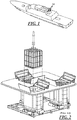
- a multiple missile carriage and launch guidance module is generally shown at 10 in Figures 1 , and 3-8 .
- the module 10 may include eight generally parallel missile launch rails 12 as best shown in Figure 7 , although, in other embodiments, any number of rails 12 may be included.
- the rails 12 may, for example, be of the type used in an M299 Missile Launch System.
- each rail 12 may be configured to carry and guide the launch of a missile 14, such as, for example, an AGM-114L Longbow HELLFIRE missile.
- the module 10 may also include a common missile carriage wall 16 carrying the missile launch rails 12 in respective positions and orientations allowing for missile carriage and launch from the rails 12.
- the common missile carriage wall 16 obviates the need to accommodate individually canisterized missiles, reducing module weight and footprint by increasing missile 14 packing density in, for example, a Littoral Combat Ship Vertical Launch System LCSVLS application.
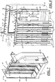
- the carriage wall 16 may comprise a carriage wall core 17 defined by generally parallel spaced-apart front and back structural skins 18, 20 of the carriage wall 16.
- the skins 18, 20 may be joined together around respective peripheral edges by fasteners, and may include a rubber O-ring gasket 24 received in a channel 26 formed around the peripheral edge of one or both of the structural skins.
- the gasket 24 may be sandwiched between the peripheral edges of the skins 18, 20 to close and seal the carriage wall core 17.
- the carriage wall skins 18, 20 may be configured to cooperate in the carriage and distribution of missile carriage loads.
- the carriage wall structural skins 18, 20 may be machined from aluminum slabs or may, in other embodiments, be formed by any suitable means from any suitable material.
- the rails 12 may be distributed between and carried by the front and back structural skins 18, 20 of the carriage wall 16.
- Four of the eight rails 12 may be carried by the front skin 18 of the carriage wall 16 and the remaining four rails 12 carried by the back skin 20 of the carriage wall 16.
- the launch rails 12 of the plurality of launch rails 12 may be spaced laterally and oriented generally parallel to one another on the front and back skins 18, 20 of the carriage wall 16.
- the front and back structural skins 18, 20 may be machined to leave hard points 28 that project integrally inward from inner surfaces of the skins 18, 20 as shown in Figure 8 .
- the hard points 28 may be configured to engage one another when the skins 18, 20 are closed together.
- the carriage wall 16 may comprise a filler 29 disposed between the front and back structural skins 18, 20 to add stiffness.
- the filler 29 may comprise, for example, aluminum honeycomb or a heat-resistant materials comprising, for example, Nomex®.
- the module 10 may include sprinkler nozzles 30 carried by and distributed between the front and back structural skins 18, 20 of the carriage wall 16. Sixteen such nozzles 30 are distributed between the front and back structural skins 18, 20 in the present embodiment, but in other embodiments any suitable number of sprinkler nozzles 30 may be used.
- Each sprinkler nozzle 30 may be connected to sprinkler piping 32 that may be connected to a fluid source 33.
- the sprinkler piping 32 may be configured to provide a fluid pathway through the carriage wall core 17 and carriage wall structural skins 18, 20 for a fluid, such as a fire suppressant fluid, to be delivered to and dispensed through the sprinkler nozzles 30.
- the sprinkler nozzles 30 may be configured to dispense fluid in a direction and manner that suppresses missile exhaust flame.
- the sprinkler nozzles 30 may be selected, configured, and/or positioned to perform in a manner that meets safety requirements for whatever type of missiles 14 are to be carried by and launched from the module 10.
- the nozzles 30 may be configured to spray fluid in a pattern that will wet-down and cool critical components such as warheads and/or pressure vessel sections of missiles 14 carried by the rails 12.
- the nozzles 30 may also or alternatively be located relatively high on the carriage wall 16 to allow gravity to help direct the spray pattern to cover a vast majority of desired areas and components.
- the sprinkler piping 32 may include an external portion 34 extending from the fluid source 33 to the carriage wall 16, and an internal portion 36 extending through the carriage wall core 17.
- the internal portion 36 may comprise machined-in piping walls that integrally extend from at least one of the inner surfaces of the structural skins 18, 20 and compress rubber seal strips 38 against an opposing inner surface or piping wall to define a fluid channel between the structural skins 18, 20.
- the sprinkler piping 32 may further comprise a penetration interface (not shown) disposed between peripheral edges of the carriage wall structural skins 18, 20.
- the penetration interface may be configured to provide fluid communication between the external and internal sprinkler piping portions 34, 36 while maintaining a seal between the peripheral edges of the carriage wall structural skins 18, 20.
- the penetration interface may comprise any suitable interface known in the art such as, for example, a fluid tube cable that extends between the carriage wall structural skins 18, 20 and that is sealed by a gland nut.
- the penetration interface may comprise a bulkhead interface comprising a permanent or quick disconnect connector mounted and sealed to one or both carriage wall structural skins 18, 20.
- the module 10 may include desiccant holder structures 42 configured to carry long-term storage desiccant within the carriage wall core 17 to maintain a dry environment within the carriage wall core 17. As shown in Figure 8 , the desiccant holder structures 42 may be machined into the inner surfaces of the carriage wall skins 18, 20 to support the desiccant material in advantageous locations within the core 17.
- the module 10 may include environmental sensors 44 disposed in the carriage wall core 17 as shown in Figure 8 .
- the environmental sensors 44 may be configured to monitor conditions within the core 17 such as temperature, humidity, shock, vibration and the like, to monitor maintenance and safety requirements.
- the carriage wall 16 may include an integral cableway 46 comprising cableway walls 48 that integrally extend from the inner surfaces of at least one of the structural skins 18, 20 and compress rubber seal strips 38 against an opposing inner surface or cableway wall to define a cable channel between the structural skins 18, 20.
- the cableway walls 48 may run through the carriage wall core 17 and cooperate to form a channel configured to receive cabling (not shown), such as missile umbilical cabling, connecting the missiles 14 mounted on the rails 12 to a launcher electronics assembly such as an M299 Launcher Electronics Assembly (LEA) from an M299 missile launch system.
- the missile umbilical cabling may carry signals related to munitions control and monitoring.
- the integral cableway 46 may also or alternatively receive rail cabling connecting the rails 12 to the launcher electronics assembly for controlling and/or powering the environmental sensors 44, and/or other systems such as access/intrusion sensors, and/or rail-related electromechanical devices.
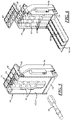
- the module 10 may include a pair of spaced-apart generally parallel end walls 50 carrying the common carriage wall 16 between them.
- the end walls 50 may be configured to be carried by mounting interfaces of a module supporting structure 52, e.g., a ship-board structure configured to carry a missile carriage and launch module 10.
- a ship-board structure 52 may include a set of C channels or I beams that may carry attachment point hardware, e.g., a Base Ship Structure (BSS) or slightly modified version thereof.
- BSS Base Ship Structure
- the module 10 may include a plenum 54 carried by and between the end walls 50.
- the plenum 54 may be configured and positioned to receive and re-direct exhaust gases from missiles 14 being launched from the module 10.
- the plenum 54 may direct the exhaust gases to a discharge chute 56 configured to direct gases up through an uptake hatch 58 level with a deck of a ship in which the module 10 is mounted as best shown in Figure 6 .
- the plenum 54 may include siliconized ablatives on interior surface areas of the plenum 54 where missile exhaust impinges, and may include other types of ablatives on other interior surface areas.
- the module 10 may include a module lid 60 (or deck interface) carried by, and connected to and sealed by any suitable means to a top edge of the carriage wall 16.
- the module lid 60 may be connected and sealed by any suitable means to top edges of the end walls 50.
- the module lid 60 may be mounted flush with the deck as shown in Figure 3 , and may include a rigid rectangular opening grid which may support flexible membranes configured to tear open when missiles 14 are launched through them.
- the carriage wall 16, module lid 60, plenum 54, and end walls 50 may be interconnected in such a way as to provide structural stiffness between these elements and to transfer loads from the carriage wall 16 and plenum to mounting interfaces of a structure, e.g., a ship-board structure, which is to carry the module 10.
- the end walls 50 may be connected by any suitable means at or adjacent respective top ends to the module lid 60. At or adjacent respective lower ends of the end walls 50, the end walls 50 may be connected to the plenum 54. The end walls 50 may be connected along inner vertical median regions to respective side edges of the carriage wall 16. The end walls 50 may thus support the plenum 54 in a position to receive and re-direct exhaust gases from missiles 14 being launched from the module 10, and to provide structural rigidity between the carriage wall 16, module lid, and the mounting interfaces of a structure carrying the module 10.
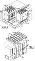
- the module 10 may include front and back generally rectangular shell covers 62 removably disposed across and closing respective front and back module openings.
- the front module opening may be defined by front edges of the module lid 60, end walls 50, and plenum 54.
- the back opening may be defined by back edges of the module lid 60, end walls 50, and plenum 54.
- the shell covers 62 may be removable to provide access to the rails 12 and/or missiles 14 carried by the rails 12.
- each shell cover 62 may comprise a main cover panel 64 shaped to be removably disposed across and close a module opening 65, and 3 missile separator panels 66 integrally extending from the main cover panel 64.
- the missile separator panels 66 may be spaced apart and configured to engage the carriage wall 16 and divide the spaces between the carriage wall 16 and the shell covers 62 into cells for individually housing missiles 14 carried by the rails 12 to protect such missiles 14 from each others' exhaust during launch. While the Figures show three missile separator panels 66 being used to separate four missiles 14 per shell cover 62, other embodiments may employ shell covers 62 configured with either more or fewer separator panels 66 corresponding to the various numbers of rails 12, missiles 14, etc. included in that embodiment.
- the separator panels 66 may be sealed against outer surfaces of the carriage wall structural skins by, for example, linear wedge seals 68 configured to receive and engage mating linear hooks 76, as shown in Figures 9-14 .
- the linear wedge seals 68 may comprise a sliding clamp 72, a brace 70, and mounting bolts 74 configured to attach the sliding clamp 72 to the brace 70.
- the sliding clamp 72 may include diagonal slots configured to receive the mounting bolts 74, such that the sliding clamp 72 may slide around the mounting bolts 74 along a path that allows it to approach and withdraw from the brace 70 as shown in Figure 11 and 12 .
- the linear wedge seal 68 may be configured to receive the mating linear hook 76 between the brace 70 and the sliding clamp 72, and may be configured to seal the linear hook 76 between the brace 70 and the sliding clamp 72 by sliding the sliding clamp 70 along the path allowed by the diagonal slots 76 until it establishes a compression seal with the brace 70 and the linear hook 76 as shown in Figure 14 .
- one of the linear hook 76 or linear wedge seal 68 may be carried by the carriage wall 16, the end walls 50, and/or by any of the main cover or separator panels 64, 66, such that each linear hook 76 may engage a linear wedge seal 68 when the cover panel 64 is installed.
- each cover panel 64 may be installed by sliding the cover panel's linear hooks 76 endwise into wedge seals 68 installed on the carriage wall 16 and end walls 60.
- the cover panels 64 may be installed vertically through the top of the module 10.
- the wedge seals 68 may be oriented to allow the shell covers 62 to be installed from the sides of the module 10, into each module opening 65, or from any other unobstructed direction.
- a typical configuration of an LCSVLS may, for example, include a Surface-to-Surface Mission Module (SSMM) comprising two Surface-to-Surface Missile Systems (SSMS).
- SSMM Surface-to-Surface Mission Module
- SSMS Surface-to-Surface Missile Systems
- Each SSMS may include three missile launch modules 10, and a Launcher Management Assembly (LMA), e.g., an M299 LMA.
- LMA Launcher Management Assembly
- Each LMA may be configured to control the three launch modules 10 in its SSMS.
- Each module 10 may be individually removable from its SSMS, allowing a module 10 with expended missiles 14 to be removed and reloaded with missiles 14 or replaced with a pre-loaded module 10.
- a multiple missile carriage and launch guidance module as described above provides a space and weight-efficient platform capable of safely storing, monitoring, and launching missiles.
- This description rather than describing limitations of an invention, only illustrates an embodiment of the invention recited in the claims. The language of this description is therefore exclusively descriptive and is non-limiting. Obviously, it's possible to modify this invention from what the description teaches. Within the scope of the claims, one may practice the invention other than as described above.
Landscapes
- Engineering & Computer Science (AREA)
- General Engineering & Computer Science (AREA)
- Aiming, Guidance, Guns With A Light Source, Armor, Camouflage, And Targets (AREA)
Applications Claiming Priority (2)
| Application Number | Priority Date | Filing Date | Title |
|---|---|---|---|
| US13/970,865 US9360277B2 (en) | 2013-08-20 | 2013-08-20 | Multiple missile carriage and launch guidance module |
| PCT/US2014/051439 WO2015053859A1 (en) | 2013-08-20 | 2014-08-18 | Multiple missile carriage and launch guidance module |
Publications (3)
| Publication Number | Publication Date |
|---|---|
| EP3036495A1 EP3036495A1 (en) | 2016-06-29 |
| EP3036495A4 EP3036495A4 (en) | 2017-04-19 |
| EP3036495B1 true EP3036495B1 (en) | 2018-03-28 |
Family
ID=52479200
Family Applications (1)
| Application Number | Title | Priority Date | Filing Date |
|---|---|---|---|
| EP14851875.6A Not-in-force EP3036495B1 (en) | 2013-08-20 | 2014-08-18 | Multiple missile carriage and launch guidance module |
Country Status (6)
| Country | Link |
|---|---|
| US (1) | US9360277B2 (enExample) |
| EP (1) | EP3036495B1 (enExample) |
| JP (1) | JP6559131B2 (enExample) |
| KR (1) | KR20160056322A (enExample) |
| IL (1) | IL244208B (enExample) |
| WO (1) | WO2015053859A1 (enExample) |
Families Citing this family (8)
| Publication number | Priority date | Publication date | Assignee | Title |
|---|---|---|---|---|
| AU2012267563B2 (en) * | 2011-06-08 | 2017-05-25 | American Technical Coatings, Inc. | Enhanced ballistic protective system |
| US20150345900A1 (en) | 2014-05-28 | 2015-12-03 | Chief Of Naval Research, Office Of Counsel | Missile Launcher System |
| US20240328752A1 (en) * | 2015-02-12 | 2024-10-03 | The Boeing Company | Aircraft weapons pod including rail launcher |
| FR3069522A1 (fr) * | 2017-07-27 | 2019-02-01 | Dcns | Plateforme navale du type comportant une fosse a missile |
| CN107478106A (zh) * | 2017-08-16 | 2017-12-15 | 董兰田 | 轨道发射地效翼对海导弹 |
| KR101978490B1 (ko) * | 2017-11-23 | 2019-08-28 | 주식회사 한화 | 로켓 포드용 케이블 보호용 차폐 구조체와 이를 구비한 로켓 포드 |
| CN112484569A (zh) * | 2020-11-24 | 2021-03-12 | 中国航空工业集团公司沈阳飞机设计研究所 | 一种机载内埋垂直发射装置 |
| RU2767097C1 (ru) * | 2021-06-16 | 2022-03-16 | Федеральное государственное казенное военное образовательное учреждение высшего образования "Военный учебно-научный центр Военно-Морского Флота "Военно-морская академия им. Адмирала Флота Советского Союза Н.Г. Кузнецова" | Универсальная корабельная пусковая установка вертикального пуска |
Family Cites Families (26)
| Publication number | Priority date | Publication date | Assignee | Title |
|---|---|---|---|---|
| US2809559A (en) * | 1943-04-02 | 1957-10-15 | Charles C Lauritsen | Rocket projector |
| NL96336C (enExample) * | 1955-10-04 | |||
| US3113486A (en) * | 1959-06-10 | 1963-12-10 | Kongelbeck Sverre | Turrent launcher |
| US3106132A (en) | 1961-03-06 | 1963-10-08 | Earl E Biermann | Launcher |
| US3138989A (en) * | 1963-02-21 | 1964-06-30 | James C Lewis | Retractable rail assemblies |
| US3738220A (en) * | 1971-04-01 | 1973-06-12 | Us Army | Flexible-fixed launch and aiming shoe/self releasing electrical and/or pyrotechnic connector for rockets |
| US3724321A (en) * | 1971-04-21 | 1973-04-03 | P Le Chevalier | Apparatus for positioning and securing a projectile holder on its pad |
| US3899953A (en) * | 1972-03-21 | 1975-08-19 | Constr Navales Ind | Self-propelled fin stabilized projectiles and launchers therefor |
| DE2930555C2 (de) * | 1979-07-27 | 1983-11-10 | Steinbock Gmbh, 8052 Moosburg | Lagerungs- und Transportsystem für Lenkflugkörper u.dgl. |
| US4470336A (en) * | 1982-08-05 | 1984-09-11 | General Dynamics, Pomona Division | Armored missile launch/shipping container |
| USH213H (en) * | 1986-06-02 | 1987-02-03 | The United States Of America As Represented By The Secretary Of The Navy | Disiccant plug for missile launcher |
| US5115711A (en) * | 1991-03-25 | 1992-05-26 | Fmc Corporation | Missile canister and method of fabrication |
| US6079310A (en) * | 1996-12-05 | 2000-06-27 | The United States Of America As Represented By The Secretary Of The Navy | Portable launcher |
| US5837919A (en) * | 1996-12-05 | 1998-11-17 | The United States Of America As Represented By The Secretary Of The Navy | Portable launcher |
| US6230604B1 (en) * | 1997-01-14 | 2001-05-15 | United Defense, L.P. | Concentric canister launcher |
| JPH10300393A (ja) * | 1997-04-21 | 1998-11-13 | Japan Radio Co Ltd | 飛翔体発射装置および飛翔体分離判定方法 |
| US5847307A (en) * | 1997-06-24 | 1998-12-08 | Northrop Grumman Corporation | Missile launcher apparatus |
| FR2781771B1 (fr) * | 1998-08-03 | 2001-02-09 | Mediterranee Const Ind | Procede de calage d'un tube dans un logement tubulaire, notamment d'un tube lance-missile |
| US6125734A (en) * | 1998-10-14 | 2000-10-03 | The United States Of America As Represented By The Secretary Of The Navy | Multi-warfare area launcher |
| JP3546148B2 (ja) * | 1998-12-07 | 2004-07-21 | 三菱重工業株式会社 | 飛昇体冷却装置 |
| US6755111B2 (en) * | 2001-06-27 | 2004-06-29 | Lockheed Martin Corporation | Missile launcher cell with exhaust gas uptake ducts, and array of such missile launcher cells |
| US6742433B2 (en) * | 2001-10-12 | 2004-06-01 | Raytheon Company | Launcher platform |
| JP2004226007A (ja) * | 2003-01-23 | 2004-08-12 | Japan Steel Works Ltd:The | ミサイルキャニスタ |
| FR2917493B1 (fr) * | 2007-06-13 | 2009-09-25 | Dcn Sa | Structure de mainten de conteneurs de missile d'un dispositif de lancement vertical de missiles |
| US8534177B2 (en) * | 2010-03-01 | 2013-09-17 | Lockheed Martin Corporation | System and method for shock isolation in a launch system |
| US8468924B2 (en) * | 2010-12-16 | 2013-06-25 | Lockheed Martin Corporation | Stowable elevating trainable launcher (SETL) |
-
2013
- 2013-08-20 US US13/970,865 patent/US9360277B2/en not_active Expired - Fee Related
-
2014
- 2014-08-18 KR KR1020167007175A patent/KR20160056322A/ko not_active Ceased
- 2014-08-18 WO PCT/US2014/051439 patent/WO2015053859A1/en not_active Ceased
- 2014-08-18 EP EP14851875.6A patent/EP3036495B1/en not_active Not-in-force
- 2014-08-18 JP JP2016536346A patent/JP6559131B2/ja not_active Expired - Fee Related
-
2016
- 2016-02-21 IL IL244208A patent/IL244208B/en active IP Right Grant
Non-Patent Citations (1)
| Title |
|---|
| None * |
Also Published As
| Publication number | Publication date |
|---|---|
| JP2016531266A (ja) | 2016-10-06 |
| JP6559131B2 (ja) | 2019-08-14 |
| IL244208B (en) | 2019-09-26 |
| WO2015053859A1 (en) | 2015-04-16 |
| IL244208A0 (en) | 2016-04-21 |
| US9360277B2 (en) | 2016-06-07 |
| EP3036495A4 (en) | 2017-04-19 |
| US20150053073A1 (en) | 2015-02-26 |
| EP3036495A1 (en) | 2016-06-29 |
| KR20160056322A (ko) | 2016-05-19 |
Similar Documents
| Publication | Publication Date | Title |
|---|---|---|
| EP3036495B1 (en) | Multiple missile carriage and launch guidance module | |
| US10203180B2 (en) | Missile canister gated obturator | |
| EP2781876B1 (en) | Louver armor | |
| US6029933A (en) | Fire resistant pressure relief panel assembly | |
| DK2920062T3 (en) | Boat with electric drive | |
| US8443707B2 (en) | Self-contained munition gas management system | |
| US5153367A (en) | Cocoon launcher and storage system | |
| US6755111B2 (en) | Missile launcher cell with exhaust gas uptake ducts, and array of such missile launcher cells | |
| RU2393411C2 (ru) | Конструкция крепления ракетных контейнеров устройства вертикального запуска ракет | |
| US10408567B1 (en) | Modular missile launcher | |
| RU2382314C1 (ru) | Модульная многоместная корабельная пусковая установка вертикального пуска | |
| KR101288983B1 (ko) | 잠수함 | |
| RU2213924C1 (ru) | Модульная многоместная корабельная пусковая установка вертикального пуска | |
| US7159501B1 (en) | Stackable in-line surface missile launch system for a modular payload bay | |
| RU2362958C1 (ru) | Корабельная пусковая система | |
| RU44175U1 (ru) | Модульная многоместная корабельная пусковая установка вертикального пуска | |
| US5924377A (en) | Modular enclosure system suitable for shipboard use | |
| US11225333B2 (en) | Fuel tank inerting system | |
| RU2210520C1 (ru) | Подводное судно | |
| RU2306520C2 (ru) | Транспортно-заряжающий контейнер забашенного автомата заряжания танковой пушки | |
| RU2552397C1 (ru) | Модульная многоместная корабельная пусковая установка вертикального пуска | |
| Kulesz | MK 41 vertical launching system fleet application |
Legal Events
| Date | Code | Title | Description |
|---|---|---|---|
| PUAI | Public reference made under article 153(3) epc to a published international application that has entered the european phase |
Free format text: ORIGINAL CODE: 0009012 |
|
| 17P | Request for examination filed |
Effective date: 20160317 |
|
| AK | Designated contracting states |
Kind code of ref document: A1 Designated state(s): AL AT BE BG CH CY CZ DE DK EE ES FI FR GB GR HR HU IE IS IT LI LT LU LV MC MK MT NL NO PL PT RO RS SE SI SK SM TR |
|
| AX | Request for extension of the european patent |
Extension state: BA ME |
|
| DAX | Request for extension of the european patent (deleted) | ||
| A4 | Supplementary search report drawn up and despatched |
Effective date: 20170322 |
|
| RIC1 | Information provided on ipc code assigned before grant |
Ipc: F41F 3/073 20060101ALI20170316BHEP Ipc: F41F 3/04 20060101AFI20170316BHEP Ipc: F41F 3/077 20060101ALN20170316BHEP |
|
| GRAP | Despatch of communication of intention to grant a patent |
Free format text: ORIGINAL CODE: EPIDOSNIGR1 |
|
| STAA | Information on the status of an ep patent application or granted ep patent |
Free format text: STATUS: GRANT OF PATENT IS INTENDED |
|
| RIC1 | Information provided on ipc code assigned before grant |
Ipc: F41F 3/077 20060101ALN20170929BHEP Ipc: F41F 3/04 20060101AFI20170929BHEP Ipc: F41F 3/073 20060101ALI20170929BHEP |
|
| INTG | Intention to grant announced |
Effective date: 20171018 |
|
| GRAS | Grant fee paid |
Free format text: ORIGINAL CODE: EPIDOSNIGR3 |
|
| GRAA | (expected) grant |
Free format text: ORIGINAL CODE: 0009210 |
|
| STAA | Information on the status of an ep patent application or granted ep patent |
Free format text: STATUS: THE PATENT HAS BEEN GRANTED |
|
| AK | Designated contracting states |
Kind code of ref document: B1 Designated state(s): AL AT BE BG CH CY CZ DE DK EE ES FI FR GB GR HR HU IE IS IT LI LT LU LV MC MK MT NL NO PL PT RO RS SE SI SK SM TR |
|
| REG | Reference to a national code |
Ref country code: GB Ref legal event code: FG4D |
|
| REG | Reference to a national code |
Ref country code: CH Ref legal event code: EP |
|
| REG | Reference to a national code |
Ref country code: AT Ref legal event code: REF Ref document number: 983831 Country of ref document: AT Kind code of ref document: T Effective date: 20180415 |
|
| REG | Reference to a national code |
Ref country code: IE Ref legal event code: FG4D |
|
| REG | Reference to a national code |
Ref country code: DE Ref legal event code: R096 Ref document number: 602014023158 Country of ref document: DE |
|
| PG25 | Lapsed in a contracting state [announced via postgrant information from national office to epo] |
Ref country code: FI Free format text: LAPSE BECAUSE OF FAILURE TO SUBMIT A TRANSLATION OF THE DESCRIPTION OR TO PAY THE FEE WITHIN THE PRESCRIBED TIME-LIMIT Effective date: 20180328 Ref country code: NO Free format text: LAPSE BECAUSE OF FAILURE TO SUBMIT A TRANSLATION OF THE DESCRIPTION OR TO PAY THE FEE WITHIN THE PRESCRIBED TIME-LIMIT Effective date: 20180628 Ref country code: LT Free format text: LAPSE BECAUSE OF FAILURE TO SUBMIT A TRANSLATION OF THE DESCRIPTION OR TO PAY THE FEE WITHIN THE PRESCRIBED TIME-LIMIT Effective date: 20180328 Ref country code: HR Free format text: LAPSE BECAUSE OF FAILURE TO SUBMIT A TRANSLATION OF THE DESCRIPTION OR TO PAY THE FEE WITHIN THE PRESCRIBED TIME-LIMIT Effective date: 20180328 |
|
| REG | Reference to a national code |
Ref country code: NL Ref legal event code: MP Effective date: 20180328 |
|
| REG | Reference to a national code |
Ref country code: LT Ref legal event code: MG4D |
|
| REG | Reference to a national code |
Ref country code: FR Ref legal event code: PLFP Year of fee payment: 5 |
|
| PG25 | Lapsed in a contracting state [announced via postgrant information from national office to epo] |
Ref country code: RS Free format text: LAPSE BECAUSE OF FAILURE TO SUBMIT A TRANSLATION OF THE DESCRIPTION OR TO PAY THE FEE WITHIN THE PRESCRIBED TIME-LIMIT Effective date: 20180328 Ref country code: BG Free format text: LAPSE BECAUSE OF FAILURE TO SUBMIT A TRANSLATION OF THE DESCRIPTION OR TO PAY THE FEE WITHIN THE PRESCRIBED TIME-LIMIT Effective date: 20180628 Ref country code: GR Free format text: LAPSE BECAUSE OF FAILURE TO SUBMIT A TRANSLATION OF THE DESCRIPTION OR TO PAY THE FEE WITHIN THE PRESCRIBED TIME-LIMIT Effective date: 20180629 Ref country code: SE Free format text: LAPSE BECAUSE OF FAILURE TO SUBMIT A TRANSLATION OF THE DESCRIPTION OR TO PAY THE FEE WITHIN THE PRESCRIBED TIME-LIMIT Effective date: 20180328 Ref country code: LV Free format text: LAPSE BECAUSE OF FAILURE TO SUBMIT A TRANSLATION OF THE DESCRIPTION OR TO PAY THE FEE WITHIN THE PRESCRIBED TIME-LIMIT Effective date: 20180328 |
|
| PG25 | Lapsed in a contracting state [announced via postgrant information from national office to epo] |
Ref country code: EE Free format text: LAPSE BECAUSE OF FAILURE TO SUBMIT A TRANSLATION OF THE DESCRIPTION OR TO PAY THE FEE WITHIN THE PRESCRIBED TIME-LIMIT Effective date: 20180328 Ref country code: RO Free format text: LAPSE BECAUSE OF FAILURE TO SUBMIT A TRANSLATION OF THE DESCRIPTION OR TO PAY THE FEE WITHIN THE PRESCRIBED TIME-LIMIT Effective date: 20180328 Ref country code: NL Free format text: LAPSE BECAUSE OF FAILURE TO SUBMIT A TRANSLATION OF THE DESCRIPTION OR TO PAY THE FEE WITHIN THE PRESCRIBED TIME-LIMIT Effective date: 20180328 Ref country code: PL Free format text: LAPSE BECAUSE OF FAILURE TO SUBMIT A TRANSLATION OF THE DESCRIPTION OR TO PAY THE FEE WITHIN THE PRESCRIBED TIME-LIMIT Effective date: 20180328 Ref country code: ES Free format text: LAPSE BECAUSE OF FAILURE TO SUBMIT A TRANSLATION OF THE DESCRIPTION OR TO PAY THE FEE WITHIN THE PRESCRIBED TIME-LIMIT Effective date: 20180328 Ref country code: AL Free format text: LAPSE BECAUSE OF FAILURE TO SUBMIT A TRANSLATION OF THE DESCRIPTION OR TO PAY THE FEE WITHIN THE PRESCRIBED TIME-LIMIT Effective date: 20180328 |
|
| PG25 | Lapsed in a contracting state [announced via postgrant information from national office to epo] |
Ref country code: SK Free format text: LAPSE BECAUSE OF FAILURE TO SUBMIT A TRANSLATION OF THE DESCRIPTION OR TO PAY THE FEE WITHIN THE PRESCRIBED TIME-LIMIT Effective date: 20180328 Ref country code: SM Free format text: LAPSE BECAUSE OF FAILURE TO SUBMIT A TRANSLATION OF THE DESCRIPTION OR TO PAY THE FEE WITHIN THE PRESCRIBED TIME-LIMIT Effective date: 20180328 Ref country code: CZ Free format text: LAPSE BECAUSE OF FAILURE TO SUBMIT A TRANSLATION OF THE DESCRIPTION OR TO PAY THE FEE WITHIN THE PRESCRIBED TIME-LIMIT Effective date: 20180328 |
|
| REG | Reference to a national code |
Ref country code: AT Ref legal event code: MK05 Ref document number: 983831 Country of ref document: AT Kind code of ref document: T Effective date: 20180328 |
|
| PG25 | Lapsed in a contracting state [announced via postgrant information from national office to epo] |
Ref country code: PT Free format text: LAPSE BECAUSE OF FAILURE TO SUBMIT A TRANSLATION OF THE DESCRIPTION OR TO PAY THE FEE WITHIN THE PRESCRIBED TIME-LIMIT Effective date: 20180730 |
|
| REG | Reference to a national code |
Ref country code: DE Ref legal event code: R097 Ref document number: 602014023158 Country of ref document: DE |
|
| PG25 | Lapsed in a contracting state [announced via postgrant information from national office to epo] |
Ref country code: AT Free format text: LAPSE BECAUSE OF FAILURE TO SUBMIT A TRANSLATION OF THE DESCRIPTION OR TO PAY THE FEE WITHIN THE PRESCRIBED TIME-LIMIT Effective date: 20180328 Ref country code: DK Free format text: LAPSE BECAUSE OF FAILURE TO SUBMIT A TRANSLATION OF THE DESCRIPTION OR TO PAY THE FEE WITHIN THE PRESCRIBED TIME-LIMIT Effective date: 20180328 |
|
| PLBE | No opposition filed within time limit |
Free format text: ORIGINAL CODE: 0009261 |
|
| STAA | Information on the status of an ep patent application or granted ep patent |
Free format text: STATUS: NO OPPOSITION FILED WITHIN TIME LIMIT |
|
| 26N | No opposition filed |
Effective date: 20190103 |
|
| PG25 | Lapsed in a contracting state [announced via postgrant information from national office to epo] |
Ref country code: MC Free format text: LAPSE BECAUSE OF FAILURE TO SUBMIT A TRANSLATION OF THE DESCRIPTION OR TO PAY THE FEE WITHIN THE PRESCRIBED TIME-LIMIT Effective date: 20180328 |
|
| REG | Reference to a national code |
Ref country code: CH Ref legal event code: PL |
|
| PG25 | Lapsed in a contracting state [announced via postgrant information from national office to epo] |
Ref country code: LI Free format text: LAPSE BECAUSE OF NON-PAYMENT OF DUE FEES Effective date: 20180831 Ref country code: CH Free format text: LAPSE BECAUSE OF NON-PAYMENT OF DUE FEES Effective date: 20180831 Ref country code: LU Free format text: LAPSE BECAUSE OF NON-PAYMENT OF DUE FEES Effective date: 20180818 |
|
| REG | Reference to a national code |
Ref country code: BE Ref legal event code: MM Effective date: 20180831 |
|
| REG | Reference to a national code |
Ref country code: IE Ref legal event code: MM4A |
|
| PG25 | Lapsed in a contracting state [announced via postgrant information from national office to epo] |
Ref country code: SI Free format text: LAPSE BECAUSE OF FAILURE TO SUBMIT A TRANSLATION OF THE DESCRIPTION OR TO PAY THE FEE WITHIN THE PRESCRIBED TIME-LIMIT Effective date: 20180328 |
|
| PG25 | Lapsed in a contracting state [announced via postgrant information from national office to epo] |
Ref country code: IE Free format text: LAPSE BECAUSE OF NON-PAYMENT OF DUE FEES Effective date: 20180818 |
|
| PG25 | Lapsed in a contracting state [announced via postgrant information from national office to epo] |
Ref country code: BE Free format text: LAPSE BECAUSE OF NON-PAYMENT OF DUE FEES Effective date: 20180831 |
|
| PGFP | Annual fee paid to national office [announced via postgrant information from national office to epo] |
Ref country code: IT Payment date: 20190826 Year of fee payment: 6 Ref country code: DE Payment date: 20190828 Year of fee payment: 6 Ref country code: FR Payment date: 20190826 Year of fee payment: 6 |
|
| PGFP | Annual fee paid to national office [announced via postgrant information from national office to epo] |
Ref country code: GB Payment date: 20190827 Year of fee payment: 6 |
|
| PG25 | Lapsed in a contracting state [announced via postgrant information from national office to epo] |
Ref country code: MT Free format text: LAPSE BECAUSE OF NON-PAYMENT OF DUE FEES Effective date: 20180818 |
|
| PG25 | Lapsed in a contracting state [announced via postgrant information from national office to epo] |
Ref country code: TR Free format text: LAPSE BECAUSE OF FAILURE TO SUBMIT A TRANSLATION OF THE DESCRIPTION OR TO PAY THE FEE WITHIN THE PRESCRIBED TIME-LIMIT Effective date: 20180328 |
|
| PG25 | Lapsed in a contracting state [announced via postgrant information from national office to epo] |
Ref country code: MK Free format text: LAPSE BECAUSE OF NON-PAYMENT OF DUE FEES Effective date: 20180328 Ref country code: HU Free format text: LAPSE BECAUSE OF FAILURE TO SUBMIT A TRANSLATION OF THE DESCRIPTION OR TO PAY THE FEE WITHIN THE PRESCRIBED TIME-LIMIT; INVALID AB INITIO Effective date: 20140818 Ref country code: CY Free format text: LAPSE BECAUSE OF FAILURE TO SUBMIT A TRANSLATION OF THE DESCRIPTION OR TO PAY THE FEE WITHIN THE PRESCRIBED TIME-LIMIT Effective date: 20180328 |
|
| PG25 | Lapsed in a contracting state [announced via postgrant information from national office to epo] |
Ref country code: IS Free format text: LAPSE BECAUSE OF FAILURE TO SUBMIT A TRANSLATION OF THE DESCRIPTION OR TO PAY THE FEE WITHIN THE PRESCRIBED TIME-LIMIT Effective date: 20180728 |
|
| REG | Reference to a national code |
Ref country code: DE Ref legal event code: R119 Ref document number: 602014023158 Country of ref document: DE |
|
| GBPC | Gb: european patent ceased through non-payment of renewal fee |
Effective date: 20200818 |
|
| PG25 | Lapsed in a contracting state [announced via postgrant information from national office to epo] |
Ref country code: DE Free format text: LAPSE BECAUSE OF NON-PAYMENT OF DUE FEES Effective date: 20210302 Ref country code: IT Free format text: LAPSE BECAUSE OF NON-PAYMENT OF DUE FEES Effective date: 20200818 Ref country code: FR Free format text: LAPSE BECAUSE OF NON-PAYMENT OF DUE FEES Effective date: 20200831 |
|
| PG25 | Lapsed in a contracting state [announced via postgrant information from national office to epo] |
Ref country code: GB Free format text: LAPSE BECAUSE OF NON-PAYMENT OF DUE FEES Effective date: 20200818 |