EP3036136B1 - Method and device for regulating a brake system - Google Patents
Method and device for regulating a brake system Download PDFInfo
- Publication number
- EP3036136B1 EP3036136B1 EP14748218.6A EP14748218A EP3036136B1 EP 3036136 B1 EP3036136 B1 EP 3036136B1 EP 14748218 A EP14748218 A EP 14748218A EP 3036136 B1 EP3036136 B1 EP 3036136B1
- Authority
- EP
- European Patent Office
- Prior art keywords
- pressure
- scaling factor
- brake
- value
- wheel
- Prior art date
- Legal status (The legal status is an assumption and is not a legal conclusion. Google has not performed a legal analysis and makes no representation as to the accuracy of the status listed.)
- Not-in-force
Links
- 238000000034 method Methods 0.000 title claims description 32
- 230000001105 regulatory effect Effects 0.000 title claims description 7
- 230000008859 change Effects 0.000 claims description 11
- 238000004364 calculation method Methods 0.000 claims description 7
- 230000004048 modification Effects 0.000 claims description 2
- 238000012986 modification Methods 0.000 claims description 2
- 239000012530 fluid Substances 0.000 description 11
- 229920000122 acrylonitrile butadiene styrene Polymers 0.000 description 9
- 230000009467 reduction Effects 0.000 description 8
- 230000008569 process Effects 0.000 description 6
- 238000010586 diagram Methods 0.000 description 3
- 230000005284 excitation Effects 0.000 description 3
- 238000011217 control strategy Methods 0.000 description 2
- 230000001276 controlling effect Effects 0.000 description 2
- 230000001419 dependent effect Effects 0.000 description 2
- 230000000694 effects Effects 0.000 description 2
- 238000005070 sampling Methods 0.000 description 2
- 238000009987 spinning Methods 0.000 description 2
- 230000009471 action Effects 0.000 description 1
- 238000013016 damping Methods 0.000 description 1
- 230000004069 differentiation Effects 0.000 description 1
- 238000006073 displacement reaction Methods 0.000 description 1
- 239000007788 liquid Substances 0.000 description 1
- 238000012423 maintenance Methods 0.000 description 1
- 210000003205 muscle Anatomy 0.000 description 1
- 230000003387 muscular Effects 0.000 description 1
- 238000004088 simulation Methods 0.000 description 1
- 230000001960 triggered effect Effects 0.000 description 1
Images


Classifications
-
- B—PERFORMING OPERATIONS; TRANSPORTING
- B60—VEHICLES IN GENERAL
- B60T—VEHICLE BRAKE CONTROL SYSTEMS OR PARTS THEREOF; BRAKE CONTROL SYSTEMS OR PARTS THEREOF, IN GENERAL; ARRANGEMENT OF BRAKING ELEMENTS ON VEHICLES IN GENERAL; PORTABLE DEVICES FOR PREVENTING UNWANTED MOVEMENT OF VEHICLES; VEHICLE MODIFICATIONS TO FACILITATE COOLING OF BRAKES
- B60T8/00—Arrangements for adjusting wheel-braking force to meet varying vehicular or ground-surface conditions, e.g. limiting or varying distribution of braking force
- B60T8/17—Using electrical or electronic regulation means to control braking
- B60T8/172—Determining control parameters used in the regulation, e.g. by calculations involving measured or detected parameters
-
- B—PERFORMING OPERATIONS; TRANSPORTING
- B60—VEHICLES IN GENERAL
- B60T—VEHICLE BRAKE CONTROL SYSTEMS OR PARTS THEREOF; BRAKE CONTROL SYSTEMS OR PARTS THEREOF, IN GENERAL; ARRANGEMENT OF BRAKING ELEMENTS ON VEHICLES IN GENERAL; PORTABLE DEVICES FOR PREVENTING UNWANTED MOVEMENT OF VEHICLES; VEHICLE MODIFICATIONS TO FACILITATE COOLING OF BRAKES
- B60T7/00—Brake-action initiating means
- B60T7/02—Brake-action initiating means for personal initiation
- B60T7/04—Brake-action initiating means for personal initiation foot actuated
- B60T7/042—Brake-action initiating means for personal initiation foot actuated by electrical means, e.g. using travel or force sensors
-
- B—PERFORMING OPERATIONS; TRANSPORTING
- B60—VEHICLES IN GENERAL
- B60T—VEHICLE BRAKE CONTROL SYSTEMS OR PARTS THEREOF; BRAKE CONTROL SYSTEMS OR PARTS THEREOF, IN GENERAL; ARRANGEMENT OF BRAKING ELEMENTS ON VEHICLES IN GENERAL; PORTABLE DEVICES FOR PREVENTING UNWANTED MOVEMENT OF VEHICLES; VEHICLE MODIFICATIONS TO FACILITATE COOLING OF BRAKES
- B60T13/00—Transmitting braking action from initiating means to ultimate brake actuator with power assistance or drive; Brake systems incorporating such transmitting means, e.g. air-pressure brake systems
- B60T13/10—Transmitting braking action from initiating means to ultimate brake actuator with power assistance or drive; Brake systems incorporating such transmitting means, e.g. air-pressure brake systems with fluid assistance, drive, or release
- B60T13/66—Electrical control in fluid-pressure brake systems
- B60T13/662—Electrical control in fluid-pressure brake systems characterised by specified functions of the control system components
-
- B—PERFORMING OPERATIONS; TRANSPORTING
- B60—VEHICLES IN GENERAL
- B60T—VEHICLE BRAKE CONTROL SYSTEMS OR PARTS THEREOF; BRAKE CONTROL SYSTEMS OR PARTS THEREOF, IN GENERAL; ARRANGEMENT OF BRAKING ELEMENTS ON VEHICLES IN GENERAL; PORTABLE DEVICES FOR PREVENTING UNWANTED MOVEMENT OF VEHICLES; VEHICLE MODIFICATIONS TO FACILITATE COOLING OF BRAKES
- B60T13/00—Transmitting braking action from initiating means to ultimate brake actuator with power assistance or drive; Brake systems incorporating such transmitting means, e.g. air-pressure brake systems
- B60T13/10—Transmitting braking action from initiating means to ultimate brake actuator with power assistance or drive; Brake systems incorporating such transmitting means, e.g. air-pressure brake systems with fluid assistance, drive, or release
- B60T13/66—Electrical control in fluid-pressure brake systems
- B60T13/68—Electrical control in fluid-pressure brake systems by electrically-controlled valves
- B60T13/686—Electrical control in fluid-pressure brake systems by electrically-controlled valves in hydraulic systems or parts thereof
-
- B—PERFORMING OPERATIONS; TRANSPORTING
- B60—VEHICLES IN GENERAL
- B60T—VEHICLE BRAKE CONTROL SYSTEMS OR PARTS THEREOF; BRAKE CONTROL SYSTEMS OR PARTS THEREOF, IN GENERAL; ARRANGEMENT OF BRAKING ELEMENTS ON VEHICLES IN GENERAL; PORTABLE DEVICES FOR PREVENTING UNWANTED MOVEMENT OF VEHICLES; VEHICLE MODIFICATIONS TO FACILITATE COOLING OF BRAKES
- B60T13/00—Transmitting braking action from initiating means to ultimate brake actuator with power assistance or drive; Brake systems incorporating such transmitting means, e.g. air-pressure brake systems
- B60T13/74—Transmitting braking action from initiating means to ultimate brake actuator with power assistance or drive; Brake systems incorporating such transmitting means, e.g. air-pressure brake systems with electrical assistance or drive
- B60T13/745—Transmitting braking action from initiating means to ultimate brake actuator with power assistance or drive; Brake systems incorporating such transmitting means, e.g. air-pressure brake systems with electrical assistance or drive acting on a hydraulic system, e.g. a master cylinder
-
- B—PERFORMING OPERATIONS; TRANSPORTING
- B60—VEHICLES IN GENERAL
- B60T—VEHICLE BRAKE CONTROL SYSTEMS OR PARTS THEREOF; BRAKE CONTROL SYSTEMS OR PARTS THEREOF, IN GENERAL; ARRANGEMENT OF BRAKING ELEMENTS ON VEHICLES IN GENERAL; PORTABLE DEVICES FOR PREVENTING UNWANTED MOVEMENT OF VEHICLES; VEHICLE MODIFICATIONS TO FACILITATE COOLING OF BRAKES
- B60T8/00—Arrangements for adjusting wheel-braking force to meet varying vehicular or ground-surface conditions, e.g. limiting or varying distribution of braking force
- B60T8/32—Arrangements for adjusting wheel-braking force to meet varying vehicular or ground-surface conditions, e.g. limiting or varying distribution of braking force responsive to a speed condition, e.g. acceleration or deceleration
- B60T8/321—Arrangements for adjusting wheel-braking force to meet varying vehicular or ground-surface conditions, e.g. limiting or varying distribution of braking force responsive to a speed condition, e.g. acceleration or deceleration deceleration
- B60T8/3255—Systems in which the braking action is dependent on brake pedal data
- B60T8/326—Hydraulic systems
-
- B—PERFORMING OPERATIONS; TRANSPORTING
- B60—VEHICLES IN GENERAL
- B60T—VEHICLE BRAKE CONTROL SYSTEMS OR PARTS THEREOF; BRAKE CONTROL SYSTEMS OR PARTS THEREOF, IN GENERAL; ARRANGEMENT OF BRAKING ELEMENTS ON VEHICLES IN GENERAL; PORTABLE DEVICES FOR PREVENTING UNWANTED MOVEMENT OF VEHICLES; VEHICLE MODIFICATIONS TO FACILITATE COOLING OF BRAKES
- B60T8/00—Arrangements for adjusting wheel-braking force to meet varying vehicular or ground-surface conditions, e.g. limiting or varying distribution of braking force
- B60T8/32—Arrangements for adjusting wheel-braking force to meet varying vehicular or ground-surface conditions, e.g. limiting or varying distribution of braking force responsive to a speed condition, e.g. acceleration or deceleration
- B60T8/34—Arrangements for adjusting wheel-braking force to meet varying vehicular or ground-surface conditions, e.g. limiting or varying distribution of braking force responsive to a speed condition, e.g. acceleration or deceleration having a fluid pressure regulator responsive to a speed condition
- B60T8/40—Arrangements for adjusting wheel-braking force to meet varying vehicular or ground-surface conditions, e.g. limiting or varying distribution of braking force responsive to a speed condition, e.g. acceleration or deceleration having a fluid pressure regulator responsive to a speed condition comprising an additional fluid circuit including fluid pressurising means for modifying the pressure of the braking fluid, e.g. including wheel driven pumps for detecting a speed condition, or pumps which are controlled by means independent of the braking system
- B60T8/404—Control of the pump unit
- B60T8/4054—Control of the pump unit involving the delivery pressure control
-
- B—PERFORMING OPERATIONS; TRANSPORTING
- B60—VEHICLES IN GENERAL
- B60T—VEHICLE BRAKE CONTROL SYSTEMS OR PARTS THEREOF; BRAKE CONTROL SYSTEMS OR PARTS THEREOF, IN GENERAL; ARRANGEMENT OF BRAKING ELEMENTS ON VEHICLES IN GENERAL; PORTABLE DEVICES FOR PREVENTING UNWANTED MOVEMENT OF VEHICLES; VEHICLE MODIFICATIONS TO FACILITATE COOLING OF BRAKES
- B60T8/00—Arrangements for adjusting wheel-braking force to meet varying vehicular or ground-surface conditions, e.g. limiting or varying distribution of braking force
- B60T8/32—Arrangements for adjusting wheel-braking force to meet varying vehicular or ground-surface conditions, e.g. limiting or varying distribution of braking force responsive to a speed condition, e.g. acceleration or deceleration
- B60T8/34—Arrangements for adjusting wheel-braking force to meet varying vehicular or ground-surface conditions, e.g. limiting or varying distribution of braking force responsive to a speed condition, e.g. acceleration or deceleration having a fluid pressure regulator responsive to a speed condition
- B60T8/40—Arrangements for adjusting wheel-braking force to meet varying vehicular or ground-surface conditions, e.g. limiting or varying distribution of braking force responsive to a speed condition, e.g. acceleration or deceleration having a fluid pressure regulator responsive to a speed condition comprising an additional fluid circuit including fluid pressurising means for modifying the pressure of the braking fluid, e.g. including wheel driven pumps for detecting a speed condition, or pumps which are controlled by means independent of the braking system
- B60T8/404—Control of the pump unit
- B60T8/4059—Control of the pump unit involving the rate of delivery
-
- B—PERFORMING OPERATIONS; TRANSPORTING
- B60—VEHICLES IN GENERAL
- B60T—VEHICLE BRAKE CONTROL SYSTEMS OR PARTS THEREOF; BRAKE CONTROL SYSTEMS OR PARTS THEREOF, IN GENERAL; ARRANGEMENT OF BRAKING ELEMENTS ON VEHICLES IN GENERAL; PORTABLE DEVICES FOR PREVENTING UNWANTED MOVEMENT OF VEHICLES; VEHICLE MODIFICATIONS TO FACILITATE COOLING OF BRAKES
- B60T2270/00—Further aspects of brake control systems not otherwise provided for
- B60T2270/82—Brake-by-Wire, EHB
Definitions
- the invention relates to a method for controlling an electro-hydraulic brake system for motor vehicles, which is preferably controlled in a "brake-by-wire" mode, with a controllable by means of an electronic control and regulating unit pressure supply device which is connected or connectable with hydraulically actuated wheel brakes and by means of which the wheel brakes are hydraulically actuated via at least one pressure control valve, wherein the pressure supply device comprises a cylinder-piston arrangement with a hydraulic pressure chamber whose piston is displaceable by an electromechanical actuator relative to a rest position, wherein a target pressure value is determined for each wheel brake, wherein the cylinder-piston arrangement is controlled in such a way that a predetermined admission pressure in the hydraulic pressure space is set by displacement of the piston, which is determined from the desired pressure values, and wherein a pre-pressure actual value and a Aktuatorieriorial actual value are determined, a form pressure setpoint is determined and the form pressure setpoint and the form actual value of a regulator device are supplied as inputs, which comprises
- the "brake-by-wire" mode of brake systems leads to a mechanical-hydraulic decoupling of the operation of the brake pedal by the driver.
- the driver operates a simulator or a brake pedal feeling simulation device, the gives him the most comfortable and familiar pedal feel possible.
- brake fluid displaced into the brake circuits By this operation, but not directly, as in conventional hydraulic brake systems, brake fluid displaced into the brake circuits. Rather, during the actuation of the simulator, the braking request of the driver is determined, which then enters into the determination of a desired braking torque or desired braking pressure.
- the actual braking is then carried out by active pressure build-up in the brake circuits by means of a pressure supply device, which is controlled by a control and regulating unit. Due to the hydraulic decoupling of the brake pedal actuation from the pressure build-up, many functionalities such as ABS, ESC, TCS, hill-start assist etc. can be realized in such brake systems in a comfortable way.
- a hydraulic fallback stage is usually provided in which the driver can bring the vehicle to a standstill by muscular force upon actuation of the brake pedal when the "by-wire" mode fails or is disturbed. While in normal operation by a pedal decoupling unit, the above-described hydraulic decoupling between brake pedal operation and brake pressure build-up, this decoupling is canceled in the fallback so that the driver can move brake means directly into the brake circuits.
- a pre-pressure is actively established in a pressure chamber.
- Form here refers to the pressure in the hydraulic pressure chamber in which the pressure piston is moved.
- a method for controlling an electro-hydraulic brake system which can be operated in particular in the "brake-by-wire" mode is, for example, from DE 10 2011 076 675 A1 known.
- a braking system is regulated, which has control functions such as ABS, TCS ASR, etc., wherein each control process is assigned a scaling factor and each of the smallest of these individual scaling factors is used as the current scaling factor.
- control functions such as ABS, TCS ASR, etc.
- each control process is assigned a scaling factor and each of the smallest of these individual scaling factors is used as the current scaling factor.
- a more cautious engagement of the booster pressure regulator is made, as compared to the normal brake function in which all wheel brakes 100 are hydraulically connected to the pressure space (so that the scale factor is 1), since the setpoint speed scales down with a scaling factor according to the active control functions and thus does not interfere so much in the control loop.
- the size of the scaling factor and thus also the strength of the reduction of the unscaled pressure control variable depends on which
- a disadvantage of such a control strategy is that the concrete braking situation is only detected implicitly and therefore not very precisely by the choice of the respective factor.
- wheel-selective control interventions are performed which require a weakened engagement of the pressure regulator, however, it is not taken into account how many and which wheel brakes are actually hydraulically connected to the linear actuator.
- the scaling factor describes the current situation only to a certain extent on average or globally.
- the invention is therefore based on the object to improve a method described above such that the current braking situation is detected very accurately. Furthermore, an apparatus for carrying out such a method and an electro-hydraulic brake system are to be specified.
- this object is achieved according to the invention in that this modification consists in its multiplication by a scaling factor and the scaling factor depends exclusively on the number of brakes connected hydraulically to the hydraulic pressure chamber.
- the invention is based on the consideration that in the in the DE 10 2011 076 675 A1
- the proposed control strategy with constant scaling factors takes into account that wheel-selective interventions take place, which require a weakened intervention of the pressure regulator.
- it is not taken into account how many and which wheel brakes are actually hydraulically connected to the linear actuator, so that the scaling factor used there always provides the desired result only on average.
- an ABS control but also in other control functions, resulting from the valve activities for the pressure regulator, a constantly changing controlled system.
- the contribution of each brake in an optimized manner can preferably be detected by using its brake fluid volume to generate a specific brake pressure as a contribution.
- the volume fraction of the respective brake is taken into account in a total volume of the brake system.
- the volume fraction of the respective brake is preferably a wheel brake relative volume, which is preferably calculated or determined and then used as a predetermined value.
- the front wheel brakes a respective Radbremsenrelativvolumen of 30% and the two rear brakes each be assigned a Radbremsenrelativvolumen of 20%, so that the total relative volume of all wheel brakes in the sum of 100%.
- the method is advantageously used in a brake system with at least one control function such as ABs, TCS, ASR, etc.
- control processes regularly require the determination of a suitable actuator speed in order to carry out the control interventions as precisely as possible.
- Actuator speed is understood to mean the rotation of a shaft, in particular of the shaft of an electric motor of the actuator or of a shaft connected and / or coupled thereto.
- a relative volume is determined as the sum of Radbremsenrelativvolume the individual wheel brakes
- the respective Radbremsenrelativvolumen is calculated as the quotient of the wheel brake volume of the respective wheel brake with the total volume multiplied by the number 100, when this wheel is currently hydraulically connected and otherwise zero, and wherein the scaling factor is a function of that relative volume.
- K min is a minimum value between 0 and 1.
- K target 1.0 represents the scaling factor at which all the wheel brakes are hydraulically connected to the pressure chamber, as in the case of the normal brake function is.
- the scaling factor depends linearly on the relative volume, i. h.,
- the relative volume is linear in the function.
- a value between 0.1 and 0.4, in particular the value 0.2, is preferably selected.
- the scaling factor or its value is not immediately replaced after its recalculation, but the previous scaling factor is changed in the direction of the newly calculated scaling factor, wherein the maximum change of the scaling factor of the difference between the previous scaling factor and the newly calculated scaling factor depends.
- the change in the direction of the newly calculated scaling factor means that a difference is formed from the new value of the scaling factor and the old value of the scaling factor.
- a change value is now calculated, which may be a predetermined value or a function of the difference. This change value has the same sign as the difference and is then added to the previous scale factor to obtain the new value of the currently valid scale factor. This process is repeated at each sampling time until the target value of the scaling factor K soll is reached.
- the amount of change in magnitude is less than or equal to the difference (if it is exactly the same, there is no increase limit and the change is passed on directly).
- the state of the respective inlet valve and / or actuator switching valve is preferably taken into account.
- the states of these valves provide timely information as to whether the respective brake is currently hydraulically connected to the pressure chamber or not.
- the determination of the scaling factor is preferably carried out at regular time intervals, preferably at intervals between 1 ms and 5 ms, in particular every 2 ms. With such short Sampling intervals can be traced so fast even in a highly dynamic control process, such as a full braking or an evasive maneuver, the scaling factor that a precise adjustment of the desired brake pressure is possible.
- an electronic control and regulation unit which preferably comprises at least one control circuit, which can be realized software and / or hardware.
- the advantages of the invention are, in particular, that a precise and interference-susceptible control of the actuator is made possible by the consideration of the currently hydraulically connected brakes in the determination of the scaling factor. By damping the scaling factor, hydraulic interference can be reduced.
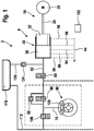
- An in FIG. 1 shown active or electro-hydraulic brake system 2 comprises a pressure supply device 8, which comprises an electromechanical actuator 14.
- the actuator 14 includes an electric motor 20 and a gear 26 and shifts the pressure buildup a pressure piston 32 in a hydraulic pressure chamber 38 in pressure build-up direction 44.
- a cylinder-piston assembly 40 is realized.
- the pressure piston 32 moves to the pressure build-up, for example, from a rest position 50 in a pressure position 56, whereby a defined volume of pressure medium from the pressure chamber 38 via a line 62, another line 74 pushed into a wheel brake 80, where it passes through an open inlet valve 88 in a brake line 94th and further shifted into a wheel brake 100.
- 100 pressure is built up in the wheel brake. Further printing positions 58, 64, 66 are shown by way of example.
- FIG. 1 only one wheel brake circuit 80 is shown.
- four wheel brake circuits 80 are usually provided, which are each connected via a separate line 62 and a switched into the respective line 62 separating valve with the pressure chamber 38.
- Each wheel brake 100 is then assigned its own valve pair 88, 106.
- An electronic control unit 102 is used to control the components described above.
- the actuator 14 is hydraulically connected to the wheel brake 80.
- a brake pressure reduction can take place in that the pressure piston 32 is moved or retracted again in the direction of its rest position 50, that is to say opposite to the pressure buildup direction 44.
- a rapid brake pressure reduction is also possible by the inlet valve 88, which a check valve 92 is connected in parallel, and an exhaust valve 106 are actuated, the exhaust valve 106 is connected in a discharge line 112, through the wheel brake 80 and the brake 100 with a brake fluid reservoir 118 or reservoir is connected.
- the inlet valve 88 or pressure control valve is closed and the outlet valve 106 is opened for a certain time.
- brake fluid or pressure fluid flows out of the wheel brake 100 via the brake line 94 into the brake fluid reservoir 118.
- This pressure reduction measure makes sense if the pressure chamber 38 serves several wheel brakes in parallel.
- a check valve 124th In a branching off from the line 62 line 120 is a check valve 124th
- valve pair 88 106 is discharged volume from the pressure chamber or the pressure chamber 38 in the brake fluid reservoir 118, whereby the piston 32, in particular during an ABS braking gradually toward the end position 58 (end stop) moves, so that after a few control cycles no further Pressure build-up is more possible.
- the line 120 and the check valve 124 liquid volume from the brake fluid reservoir 118 can be sucked back into the pressure chamber 38.
- the pressure chamber 38 for safety reasons more, in particular nikig executed with multiple pressure chambers or pressure piston, the pressure chambers the wheel circuits or brake circuits diagonally or axle (black and white) can be assigned.
- the need to adjust a predetermined system pressure or system pressure profile by means of a control method results whenever the driver requests a general brake pressure for all wheels of the motor vehicle by operating the brake pedal, or when this pressure request by an assistance function (ACC, HSA, HDC, etc.), or when a particular wheel-specific brake control function becomes active, such as ABSs, TCS or ESP.
- an assistance function ACC, HSA, HDC, etc.
- a particular wheel-specific brake control function becomes active, such as ABSs, TCS or ESP.
- the assistance functions usually require a global brake pressure for all wheels, similar to a braking action triggered by the driver using the brake applied to the brake pedal.
- the pressure with open inlet valve 88 is generated on all brake circuits equally by ancestors of the plunger or plunger 32.
- the anti-lock function ABS generally limits or reduces only the pressure applied by the pressure chamber 38 for individual wheels in order to keep them in optimal brake slip.
- TCS traction control individual wheels that are prone to spinning due to excessive drive torque are braked in a targeted manner.
- the brake system must actively generate pressure in the pressure chamber 38, which was not requested by the driver.
- the pressure from the pressure chamber 38 must then be directed individually via the respective valves 88, 106 into the respective wheel brake 100 of the wheel to be braked, while the brake circuits of the other wheels, which remain unregulated, are separated from the pressure chamber 38 by means of their inlet valves 88.
- brake pressures are also actively and selectively applied to individual wheels to affect the dynamics of the vehicle about the vertical axis.
- the form in the chamber or the pressure chamber 38 is to be adjusted so that the wheel with the highest braking pressure requirement can be reliably supplied with the necessary brake pressure.
- the pressure must be limited by the intake valve 88 belonging to the wheel being closed permanently or temporarily. If the wheel then requires a lower brake pressure than the one already set and the admission pressure is higher than the desired wheel pressure, brake fluid must be released from the wheel brake 100 into the brake fluid reservoir 118 by means of the associated outlet valve 106.
- the desired speed of the actuator or its speed can be scaled so that the changes in the rotational speed are lower and thus the interference excitations are lower, since the setpoint speed then does not engage as strongly in the control loop.
- the scaling factor is independent of the currently activated control function and is determined only on the basis of the number of hydraulically connected to the pressure chamber 38 wheel brakes 38.
- the state of the respective intake valve of the wheel brake is checked and / or the state of the respective Aktuatorschaltaltventils.
- FIG. 2 is shown in a schematic block diagram, a control circuit for performing a preferred embodiment of the method.
- a control circuit is for example a component in a device according to the invention for carrying out the method.
- the output value of the pressure regulator 140 is the target value for the actuator speed ⁇ soll, DR .
- a speed feedforward calculation module 152 determines from the desired pressure value P soll by differentiation a further actuator speed setpoint weighted with a gain factor, an additional portion ⁇ soll, FFW the actuator speed setpoint of the pressure controller 140 ⁇ soll, DR superimposed.
- the two setpoint speed components are added together in an adder 158 and supplied to a limiting function 164 for limiting to the minimum or maximum permissible setpoint speed ( ⁇ min , ⁇ max ).
- the value ⁇ soll * resulting from this operation is multiplied in a multiplication element 170 by the scaling factor K; the result of the operation is then the actuator speed setpoint ⁇ soll .
- FIG. 3 illustrates how the scaling factor K is determined. From the total relative volume V Rel, total , a target value for the scaling factor, namely K soll , is calculated in a calculation element 176. In a subtraction element 182, the final value of the scaling factor from the last iteration, K last loop , is subtracted therefrom, resulting in the difference ⁇ K of the two values. This difference is then fed to a change determination module 188, which determines a maximum change ⁇ K max of the scaling factor as a function of the difference ⁇ K. In the present case, this is done via a step function which assigns a value ⁇ K max to different value ranges of the difference ⁇ K.
- ⁇ K max is such that for a reduction in the scaling factor, that is, when K soll ⁇ K, the value for K per iteration is brought much faster to the target value K soll than K soll > K is the case because due the now smaller number of wheel brakes, which are hydraulically connected to the linear actuator, which becomes stiffer for the pressure regulator to be controlled controlled system.
Landscapes
- Engineering & Computer Science (AREA)
- Transportation (AREA)
- Mechanical Engineering (AREA)
- Physics & Mathematics (AREA)
- Fluid Mechanics (AREA)
- Regulating Braking Force (AREA)
Description
Die Erfindung betrifft ein Verfahren zur Regelung eines elektrohydraulischen Bremssystems für Kraftfahrzeuge, welches vorzugsweise in einer "Brake-by-wire"-Betriebsart ansteuerbar ist, mit einer mittels einer elektronischen Steuer- und Regeleinheit ansteuerbaren Druckbereitstellungseinrichtung, welche mit hydraulisch betätigbaren Radbremsen verbunden oder verbindbar ist und mittels welcher die Radbremsen über mindestens ein Druckregelventil hydraulisch betätigbar sind, wobei die Druckbereitstellungseinrichtung eine Zylinder-Kolben-Anordnung mit einem hydraulischen Druckraum umfasst, deren Kolben durch einen elektromechanischen Aktuator relativ zu einer Ruheposition verschiebbar ist, wobei für jede Radbremse ein Solldruckwert bestimmt ist, wobei die Zylinder-Kolben-Anordnung derart angesteuert wird, dass ein vorbestimmter Vordruck in dem hydraulischen Druckraum durch Verschiebung des Kolbens eingestellt wird, der aus den Solldruckwerten bestimmt wird, und wobei ein Vordruck-Istwert und ein Aktuatorgeschwindigkeit-Istwert ermittelt werden, ein Vordruck-Sollwert bestimmt wird und der Vordruck-Sollwert und der Vordruck-Istwert einer Reglervorrichtung als Eingangsgrößen zugeführt werden, welche einen Druckregler und einem dem Druckregler nachgeschalteten Geschwindigkeitsregler umfasst, wobei der Druckregler einen Aktuatorgeschwindigkeit-Sollwert ausgibt und dem Geschwindigkeitsregler als Eingangsgröße ein Aktuatorgeschwindigkeit-Sollwert und der Aktuatorgeschwindigkeit-Istwert zugeführt werden, und wobei der dem Geschwindigkeitsregler zugeführte Aktuatorgeschwindigkeit-Sollwert in Abhängigkeit von der Anzahl der Bremsen modifiziert wird. Sie betrifft weiterhin eine entsprechende Vorrichtung und ein Bremssystem.The invention relates to a method for controlling an electro-hydraulic brake system for motor vehicles, which is preferably controlled in a "brake-by-wire" mode, with a controllable by means of an electronic control and regulating unit pressure supply device which is connected or connectable with hydraulically actuated wheel brakes and by means of which the wheel brakes are hydraulically actuated via at least one pressure control valve, wherein the pressure supply device comprises a cylinder-piston arrangement with a hydraulic pressure chamber whose piston is displaceable by an electromechanical actuator relative to a rest position, wherein a target pressure value is determined for each wheel brake, wherein the cylinder-piston arrangement is controlled in such a way that a predetermined admission pressure in the hydraulic pressure space is set by displacement of the piston, which is determined from the desired pressure values, and wherein a pre-pressure actual value and a Aktuatorgeschwindigkeit actual value are determined, a form pressure setpoint is determined and the form pressure setpoint and the form actual value of a regulator device are supplied as inputs, which comprises a pressure regulator and a pressure regulator downstream speed regulator, the pressure regulator outputs an actuator speed setpoint and supplying to the speed controller as input an actuator speed setpoint and the actuator speed actual value, and wherein the actuator speed setpoint supplied to the speed controller is modified in dependence on the number of brakes. It further relates to a corresponding device and a brake system.
Die "Brake-by-wire"-Betriebsart von Bremssystemen, insbesondere elektrohydraulischen Bremssystemen, führt zu einer mechanisch-hydraulischen Entkopplung der Betätigung des Bremspedals durch den Fahrer. Der Fahrer betätigt dabei einen Simulator bzw. eine Bremspedalgefühlsimulationseinrichtung, die ihm ein möglichst angenehmes und vertrautes Pedalgefühl vermittelt. Durch diese Betätigung wird aber nicht unmittelbar, wie in herkömmlichen hydraulischen Bremssystemen, Bremsflüssigkeit in die Bremskreise verschoben. Vielmehr wird während der Betätigung des Simulators der Bremswunsch des Fahrers bestimmt, der dann in die Bestimmung eines Sollbremsmomentes bzw. Sollbremsdruckes eingeht. Das tatsächliche Bremsen erfolgt dann durch aktiven Druckaufbau in den Bremskreisen mit Hilfe einer Druckbereitstellungseinrichtung, die von einer Steuer- und Regeleinheit angesteuert wird. Durch die hydraulische Entkopplung der Bremspedalbetätigung von dem Druckaufbau lassen sich in derartigen Bremssystemen viele Funktionalitäten wie ABS, ESC, TCS, Hanganfahrhilfe etc. komfortabel verwirklichen.The "brake-by-wire" mode of brake systems, in particular electro-hydraulic brake systems, leads to a mechanical-hydraulic decoupling of the operation of the brake pedal by the driver. The driver operates a simulator or a brake pedal feeling simulation device, the gives him the most comfortable and familiar pedal feel possible. By this operation, but not directly, as in conventional hydraulic brake systems, brake fluid displaced into the brake circuits. Rather, during the actuation of the simulator, the braking request of the driver is determined, which then enters into the determination of a desired braking torque or desired braking pressure. The actual braking is then carried out by active pressure build-up in the brake circuits by means of a pressure supply device, which is controlled by a control and regulating unit. Due to the hydraulic decoupling of the brake pedal actuation from the pressure build-up, many functionalities such as ABS, ESC, TCS, hill-start assist etc. can be realized in such brake systems in a comfortable way.
In derartigen Bremssystemen ist gewöhnlich eine hydraulische Rückfallebene vorgesehen, in der der Fahrer das Fahrzeug durch Muskelkraft bei Betätigung des Bremspedals zum Stehen bringen kann, wenn die "by-wire"-Betriebsart ausfällt oder gestört ist. Während im Normalbetrieb durch eine Pedalentkopplungseinheit die oben beschriebene hydraulische Entkopplung zwischen Bremspedalbetätigung und Bremsdruckaufbau erfolgt, wird in der Rückfallebene diese Entkopplung aufgehoben, so dass der Fahrer direkt Bremsmittel in die Bremskreise verschieben kann.In such brake systems, a hydraulic fallback stage is usually provided in which the driver can bring the vehicle to a standstill by muscular force upon actuation of the brake pedal when the "by-wire" mode fails or is disturbed. While in normal operation by a pedal decoupling unit, the above-described hydraulic decoupling between brake pedal operation and brake pressure build-up, this decoupling is canceled in the fallback so that the driver can move brake means directly into the brake circuits.
Automatische Regelsysteme wie ABS, ESP, TCS sind aus modernen Kraftfahrzeugen nicht mehr wegzudenken und erhöhen die Sicherheit der Fahrzeuginsassen in hohem Maße. Sie greifen in der Regel dann ein, wenn eine instabile fahrdynamische Situation detektiert wird (Durchdrehen der Räder, Schleudern etc.) und überführen das Fahrzeug durch gezieltes Abbremsen und Freigeben einzelner Räder wieder in einen stabilen fahrdynamischen Zustand. Während bei konventionellen hydraulischen Bremssystemen, bei denen der gesamte Bremsdruck vom Fahrer durch Muskelkraft aufgebracht werden muss, diese Regelsysteme nur gezielt Bremsdruck verringern können und selbständig keinen höheren als den Fahrerdruck erzeugen können, sind aktive, insbesondere elektrohydraulische, Bremssysteme dafür ausgelegt, dass vom System her auch Druck selbständig bzw. aktiv erzeugt bzw. aufgebaut werden kann.Automatic control systems such as ABS, ESP, TCS have become indispensable in modern motor vehicles and greatly increase the safety of vehicle occupants. They usually intervene when an unstable dynamic driving situation is detected (spinning the wheels, skidding, etc.) and transfer the vehicle by deliberately braking and releasing individual wheels back into a stable driving dynamic state. While in conventional hydraulic braking systems, where the entire brake pressure from the driver must be applied by muscle power, these control systems can only deliberately reduce brake pressure and independently can produce no higher than the driver pressure, active, especially electro-hydraulic, braking systems are designed for that of System ago also pressure independently or actively can be generated or built.
Bei Regelungsvorgängen wird dabei in einem Druckraum aktiv ein Vordruck aufgebaut. Vordruck bezeichnet hierbei den Druck im hydraulischen Druckraum, in dem der Druckkolben verschoben wird.During control processes, a pre-pressure is actively established in a pressure chamber. Form here refers to the pressure in the hydraulic pressure chamber in which the pressure piston is moved.
Ein Verfahren zur Regelung eines elektrohydraulischen Bremssystems, das insbesondere in der "Brake-by-wire"-Betriebsart betrieben werden kann, ist beispielsweise aus der
Nachteilig bei einer derartigen Regelungsstrategie ist, dass durch die Wahl des jeweiligen Faktors die konkrete Bremssituation nur implizit und damit nicht sehr präzise erfasst wird. Es wird nämlich zwar prinzipiell berücksichtigt, dass radselektive Regeleingriffe vorgenommen werden, die einen abgeschwächten Eingriff des Druckreglers erfordern, allerdings wird nicht berücksichtigt, wie viele und welche Radbremsen nun tatsächlich hydraulisch mit dem Linearaktuator verbunden sind. Der Skalierungsfaktor beschreibt die aktuelle Situation also nur gewissermaßen im Mittel bzw. global.A disadvantage of such a control strategy is that the concrete braking situation is only detected implicitly and therefore not very precisely by the choice of the respective factor. Although in principle it is taken into account that wheel-selective control interventions are performed which require a weakened engagement of the pressure regulator, however, it is not taken into account how many and which wheel brakes are actually hydraulically connected to the linear actuator. The scaling factor describes the current situation only to a certain extent on average or globally.
Des Weiteren wird in der oben genannten Druckschrift alternativ oder in Kombination dazu vorgeschlagen, die Anzahl der Bremsen zu berücksichtigen, ohne dies weiter auszuführen.Furthermore, it is proposed in the above-cited document, alternatively or in combination, to consider the number of brakes without further elaboration.
Der Erfindung liegt daher die Aufgabe die Aufgabe zugrunde, ein oben beschriebenes Verfahren derart zu verbessern, dass die aktuelle Bremssituation sehr genau erfasst wird. Weiterhin sollen eine Vorrichtung zur Durchführung eines derartigen Verfahrens und ein elektrohydraulisches Bremssystem angegeben werden.The invention is therefore based on the object to improve a method described above such that the current braking situation is detected very accurately. Furthermore, an apparatus for carrying out such a method and an electro-hydraulic brake system are to be specified.
In Bezug auf das Verfahren wird diese Aufgabe erfindungsgemäß dadurch gelöst, dass diese Modifizierung in dessen Multiplikation mit einem Skalierungsfaktor besteht und der Skalierungsfaktor ausschließlich von der Anzahl der hydraulisch mit dem hydraulischen Druckraum verbundenen Bremsen abhängt.With regard to the method, this object is achieved according to the invention in that this modification consists in its multiplication by a scaling factor and the scaling factor depends exclusively on the number of brakes connected hydraulically to the hydraulic pressure chamber.
Vorteilhafte Ausgestaltungen der Erfindung sind Gegenstand der Unteransprüche.Advantageous embodiments of the invention are the subject of the dependent claims.
Die Erfindung geht von der Überlegung aus, dass bei der in der
Wie nunmehr erkannt wurde, führt nun eine explizite und ausschließliche Berücksichtigung der Zahl bzw. Anzahl der hydraulisch mit dem Druckraum bzw. der Vordruckkammer verbundenen Radbremsen bei der Berechnung des Skalierungsfaktors zu deutlichen Verbesserungen in der Regelgüte des Systemdruckreglers und damit auch in der Güte der Bremsung. Insbesondere im Falle einer ABS-Regelung, aber auch bei anderen Bremsregelungs- bzw. Bremsassistenzfunktionen, ergibt sich auf Grund der Ventilaktivitäten für den Druckregler eine sich ständig ändernde Regelstrecke, so dass eine Berücksichtigung der Anzahl der hydraulisch mit dem Druckraum verbundenen Bremsen bei der Berechnung des Skalierungsfaktors zu deutlichen Verbesserungen in der Regelgüte des Systemdruckreglers und damit auch in der Güte der Bremsung führt.As has now been recognized, an explicit and exclusive consideration of the number or number of wheel brakes connected hydraulically to the pressure chamber or the admission pressure chamber in the calculation of the scaling factor now leads to significant improvements in the control quality of the system pressure regulator and therefore also in the quality of the braking. In particular, in the case of ABS control, but also in other brake control or brake assistance functions, resulting from the valve activities for the pressure regulator, a constantly changing controlled system, so that taking into account the number of hydraulically connected to the pressure chamber brakes in the calculation of Scaling factor leads to significant improvements in the control performance of the system pressure regulator and thus in the quality of the braking.
Dabei ist aber noch wichtig, in welchem Maße die einzelnen Bremsen in die Skalierung eingehen, d. h., wie ihr Beitrag jeweils in der Berechnung des Skalierungsfaktors gewichtet wird. Wie hierzu erkannt wurde, kann der Beitrag jeder Bremse in optimierter Weise bevorzugt dadurch erfasst werden, dass ihr Bremsmittelvolumen zur Erzeugung eines bestimmten Bremsdruckes als Beitrag verwendet wird. Vorteilhafterweise wird demnach bei der Bestimmung des Skalierungsfaktors der Volumenanteil der jeweiligen Bremse an einem Gesamtvolumen des Bremssystems berücksichtigt.But it is still important to what extent the individual brakes go into the scaling, d. how their contribution is weighted in each case in the calculation of the scaling factor. As has been recognized, the contribution of each brake in an optimized manner can preferably be detected by using its brake fluid volume to generate a specific brake pressure as a contribution. Advantageously, therefore, when determining the scaling factor, the volume fraction of the respective brake is taken into account in a total volume of the brake system.
Der Volumenanteil der jeweiligen Bremse ist bevorzugt ein Radbremsenrelativvolumen, welches vorzugsweise berechnet bzw. ermittelt wird und dann als vorgegebener Wert verwendet wird. So kann beispielsweise den Vorderradbremsen ein jeweiliges Radbremsenrelativvolumen von jeweils 30 % und den beiden Hinterradbremsen jeweils ein Radbremsenrelativvolumen von 20 % zugeordnet werden, so dass sich für das Gesamtrelativvolumen aller Radbremsen in der Summe 100 % ergeben.The volume fraction of the respective brake is preferably a wheel brake relative volume, which is preferably calculated or determined and then used as a predetermined value. Thus, for example, the front wheel brakes a respective Radbremsenrelativvolumen of 30% and the two rear brakes each be assigned a Radbremsenrelativvolumen of 20%, so that the total relative volume of all wheel brakes in the sum of 100%.
Das Verfahren wird vorteilhaft bei einem Bremssystem mit wenigstens einer Regelfunktion wie ABs, TCS, ASR, etc. eingesetzt. Derartige Regelungsvorgänge bedürfen regelmäßig der Bestimmung einer geeigneten Aktuatorgeschwindigkeit, um die Regeleingriffe möglichst präzise durchzuführen. Unter Aktuatorgeschwindigkeit wird die Drehung einer Welle, insbesondere der Welle eines Elektromotors des Aktuators oder einer damit gekoppelten, verbundenen und/oder angetriebenen Welle verstanden.The method is advantageously used in a brake system with at least one control function such as ABs, TCS, ASR, etc. Such control processes regularly require the determination of a suitable actuator speed in order to carry out the control interventions as precisely as possible. Actuator speed is understood to mean the rotation of a shaft, in particular of the shaft of an electric motor of the actuator or of a shaft connected and / or coupled thereto.
Zur Berücksichtigung der einzelnen momentan hydraulisch angeschlossenen Bremsen wird vorteilhafterweise ein Relativvolumen bestimmt als Summe von Radbremsenrelativvolumina der einzelnen Radbremsen, wobei das jeweilige Radbremsenrelativvolumen berechnet wird als Quotient des Radbremsenvolumens der jeweiligen Radbremse mit dem Gesamtvolumen multipliziert mit der Zahl 100, wenn diese Radbremse gerade hydraulisch verbunden ist und ansonsten Null ist, und wobei der Skalierungsfaktor eine Funktion dieses Relativvolumens ist.To account for the individual currently hydraulically connected brakes advantageously a relative volume is determined as the sum of Radbremsenrelativvolume the individual wheel brakes, the respective Radbremsenrelativvolumen is calculated as the quotient of the wheel brake volume of the respective wheel brake with the total volume multiplied by the
Im Allgemeinen gilt für den Skalierungsfaktor KSoll die Ungleichung 0 < KMin <= KSoll <= 1.0, wobei KMin ein minimaler Wert zwischen 0 und 1 ist. Im Folgenden wird, wie durch diese Ungleichung ausgedrückt, eine Reduktion oder Gleichbehaltung der Aktuatorsollgeschwindigkeit in Betracht gezogen, wobei der Wert KSoll = 1.0 den Skalierungsfaktor repräsentiert, bei dem alle Radbremsen hydraulisch mit dem Druckraum verbunden sind, wie dies beispielsweise in der Normalbremsfunktion der Fall ist.In general, for the scaling factor K setpoint, the inequality 0 <K min <= K setpoint <= 1.0 applies, where K min is a minimum value between 0 and 1. In the following, as expressed by this inequality, a reduction or maintenance of the actuator target speed is considered, wherein the value K target = 1.0 represents the scaling factor at which all the wheel brakes are hydraulically connected to the pressure chamber, as in the case of the normal brake function is.
In einer bevorzugten Ausführungsform hängt der Skalierungsfaktor linear von dem Relativvolumen ab, d. h., das Relativvolumen geht linear in die Funktion ein.In a preferred embodiment, the scaling factor depends linearly on the relative volume, i. h., The relative volume is linear in the function.
Bevorzugt wird Skalierungsfaktor berechnet gemäß Ksoll = Kmin + (1.0 - Kmin) * Vrel, gesamt/100, wobei Vrel, gesamt das Relativvolumen der hydraulisch mit dem Druckraum verbundenen Radbremsen bezeichnet. Da das Relativvolumen Vrel, gesamt Werte zwischen 0 und 100 annimmt, ergibt sich für den Skalierungsfaktor ein linear von dem Relativvolumen abhängiger Wertebereich von Kmin bis 1.0.Scaling factor is preferably calculated according to K soll = K min + (1.0 - K min ) * V rel, total / 100, where V rel, total refers to the relative volume of the hydraulically connected to the pressure chamber wheel brakes. Since the relative volume V rel , overall assumes values between 0 and 100, the scaling factor results in a value range which is linearly dependent on the relative volume, from K min to 1.0.
Für den minimalen Skalierungsfaktor Kmin wird dabei vorzugsweise ein Wert zwischen 0.1 und 0.4, insbesondere der Wert 0.2 gewählt.For the minimum scaling factor K min , a value between 0.1 and 0.4, in particular the value 0.2, is preferably selected.
Auf Grund der Berechnungsmethode des Relativvolumens weist dieses keinen kontinuierlichen Zeitverlauf auf (es weist gewöhnlich immer dann Sprünge auf, wenn eine Radbremse hydraulisch dazu geschaltet oder getrennt wird) . Wird nun der neu berechnete Skalierungsfaktor direkt zur Regelung verwendet, kann dies zu ruckartigen bzw. plötzlichen Sprüngen in der Aktuatorsollgeschwindigkeit führen und damit zu Störanregungen durch den Druckregler führen. Aus diesem Grund ist es vorteilhaft, den Verlauf des Skalierungsfaktors gewissermaßen zu dämpfen bzw. zu glätten.Due to the relative volume calculation method, this does not have a continuous time course (it usually has discontinuities whenever a wheel brake is hydraulically switched or disconnected). Will now the newly calculated Scaling factor directly used for control, this can lead to sudden or sudden jumps in the Aktuatorsollgeschwindigkeit and thus lead to disturbances by the pressure regulator. For this reason, it is advantageous to dampen or smooth the course of the scaling factor as it were.
Vorteilhafterweise wird daher der Skalierungsfaktor bzw. sein Wert nach seiner Neuberechnung nicht unmittelbar ersetzt, sondern der bisherige Skalierungsfaktor wird in Richtung des neu berechneten Skalierungsfaktors geändert, wobei die maximale Änderung des Skalierungsfaktors von der Differenz zwischen dem bisherigen Skalierungsfaktor und dem neu berechneten Skalierungsfaktor abhängt. Die Änderung in Richtung des neu berechneten Skalierungsfaktors bedeutet dabei, dass eine Differenz aus dem neuen Wert des Skalierungsfaktors und dem alten Wert des Skalierungsfaktors gebildet wird. In Abhängigkeit von der Größe dieser Differenz wird nun ein Änderungswert berechnet, der ein vorher festgelegter Wert oder eine Funktion der Differenz sein kann. Dieser Änderungswert hat das gleiche Vorzeichen wie die Differenz und wird dann zu dem bisherigen Skalierungsfaktor addiert, um den neuen Wert des aktuell gültigen Skalierungsfaktors zu erhalten. Dieser Vorgang wird zu jedem Abtastzeitpunkt wiederholt, bis der Zielwert des Skalierungsfaktors Ksoll erreicht ist. Vorteilhafterweise ist der Änderungswert vom Betrag her kleiner oder gleich groß der Differenz (ist er genau gleich groß, erfolgt keine Anstiegsbegrenzung und die Änderung wird direkt weitergegeben).Advantageously, therefore, the scaling factor or its value is not immediately replaced after its recalculation, but the previous scaling factor is changed in the direction of the newly calculated scaling factor, wherein the maximum change of the scaling factor of the difference between the previous scaling factor and the newly calculated scaling factor depends. The change in the direction of the newly calculated scaling factor means that a difference is formed from the new value of the scaling factor and the old value of the scaling factor. Depending on the size of this difference, a change value is now calculated, which may be a predetermined value or a function of the difference. This change value has the same sign as the difference and is then added to the previous scale factor to obtain the new value of the currently valid scale factor. This process is repeated at each sampling time until the target value of the scaling factor K soll is reached. Advantageously, the amount of change in magnitude is less than or equal to the difference (if it is exactly the same, there is no increase limit and the change is passed on directly).
Zur Bestimmung des jeweiligen Radbremsenrelativvolumens wird vorzugsweise der Zustand des jeweiligen Einlassventils und/oder Aktuatorzuschaltventils berücksichtigt. Die Zustände dieser Ventile geben zeitgenau Auskunft darüber, ob die jeweilige Bremse momentan hydraulisch mit dem Druckraum verbunden ist oder nicht.In order to determine the respective wheel brake relative volume, the state of the respective inlet valve and / or actuator switching valve is preferably taken into account. The states of these valves provide timely information as to whether the respective brake is currently hydraulically connected to the pressure chamber or not.
Die Bestimmung des Skalierungsfaktors erfolgt vorzugsweise in regelmäßigen zeitlichen Abständen, bevorzugt in Abständen zwischen 1 ms und 5 ms, insbesondere alle 2 ms. Bei derart kurzen Abtastintervallen kann auch bei einem hochdynamischen Regelvorgang, wie beispielsweise einer Vollbremsung oder einem Ausweichmanöver, der Skalierungsfaktor so schnell nachgefahren werden, dass eine präzise Einstellung des Sollbremsdruckes möglich ist.The determination of the scaling factor is preferably carried out at regular time intervals, preferably at intervals between 1 ms and 5 ms, in particular every 2 ms. With such short Sampling intervals can be traced so fast even in a highly dynamic control process, such as a full braking or an evasive maneuver, the scaling factor that a precise adjustment of the desired brake pressure is possible.
In Bezug auf die Vorrichtung wird die oben genannte Aufgabe erfindungsgemäß gelöst mit Mitteln zur Ausführung eines oben beschriebenen Verfahrens. Dazu ist insbesondere eine elektronische Steuer- und Regeleinheit vorgesehen, welche bevorzugt wenigstens eine Regelschaltung umfasst, welche software- und/oder hardwaremäßig realisiert sein kann.With respect to the device, the above object is achieved according to the invention with means for carrying out a method described above. For this purpose, in particular, an electronic control and regulation unit is provided, which preferably comprises at least one control circuit, which can be realized software and / or hardware.
In Bezug auf das Bremssystem wird die oben genannte Aufgabe erfindungsgemäß gelöst mit einer derartigen Vorrichtung.With respect to the brake system, the above object is achieved according to the invention with such a device.
Die Vorteile der Erfindung liegen insbesondere darin, dass durch die Berücksichtigung der aktuell hydraulisch angeschlossenen Bremsen bei der Bestimmung des Skalierungsfaktors eine präzise und störanregungsunanfällige Ansteuerung des Aktuators ermöglicht wird. Durch eine Dämpfung des Skalierungsfaktors können hydraulische Störanregungen verringert werden.The advantages of the invention are, in particular, that a precise and interference-susceptible control of the actuator is made possible by the consideration of the currently hydraulically connected brakes in the determination of the scaling factor. By damping the scaling factor, hydraulic interference can be reduced.
Ein Ausführungsbeispiel der Erfindung wird anhand einer Zeichnung näher erläutert. Darin zeigen in stark schematisierter Darstellung:
-
FIG. 1 ein elektrohydraulisches Bremssystem mit einer Steuer- und Regeleinheit zur Durchführung des Verfahrens in einer bevorzugten Ausführungsform, -
FIG. 2 ein Blockschaltbild einer Regelschaltung zur Durchführung einer Anzahl der Verfahrensschritte, und -
FIG. 3 ein Blockschaltbild einer weiteren Regelschaltung zur Durchführung einer Anzahl der Verfahrensschritte.
-
FIG. 1 an electrohydraulic brake system with a control and regulation unit for carrying out the method in a preferred embodiment, -
FIG. 2 a block diagram of a control circuit for performing a number of method steps, and -
FIG. 3 a block diagram of another control circuit for performing a number of method steps.
Gleiche Teile sind in allen Figuren mit denselben Bezugszeichen versehen.Identical parts are provided with the same reference numerals in all figures.
Ein in
Ein Bremsdruckabbau kann erfolgen, indem der Druckkolben 32 wieder in Richtung seiner Ruheposition 50, also entgegengesetzt zur Druckaufbaurichtung 44, verschoben bzw. zurückgefahren wird. Ein schneller Bremsdruckabbau, wie er bei einem ABS-Regelvorgang benötigt wird, ist auch möglich, indem das Einlassventil 88, dem ein Rückschlagventil 92 parallel geschaltet ist, und ein Auslassventil 106 betätigt werden, wobei das Auslassventil 106 in eine Abfuhrleitung 112 geschaltet ist, durch die der Radbremskreis 80 bzw. die Bremse 100 mit einem Bremsflüssigkeitsbehälter 118 bzw. Reservoir verbunden ist. Zum Abbau des Bremsdruckes wird das Einlassventil 88 bzw. Druckregelventil geschlossen und das Auslassventil 106 für eine bestimmte Zeit geöffnet. Dadurch strömt Bremsflüssigkeit bzw. Druckmittel aus der Radbremse 100 über die Bremsleitung 94 in den Bremsflüssigkeitsbehälter 118. Diese Maßnahme des Druckabbaus ist dann sinnvoll, wenn der Druckraum 38 mehrere Radbremsen parallel bedient. In eine von der Leitung 62 abzweigende Leitung 120 ist ein Rückschlagventil 124.A brake pressure reduction can take place in that the
Insbesondere beim radindividuellen Druckabbau über das in
In alternativer Ausgestaltung des Bremssystems 2 kann der Druckraum 38 aus Sicherheitsgründen mehr-, insbesondere zweikreisig, ausgeführt sein mit mehreren Druckkammern bzw. Druckkolben, wobei die Druckkammern den Radkreisen bzw. Bremskreisen diagonal oder achsweise (Schwarz-weiß) zugeordnet sein können.In an alternative embodiment of the brake system 2, the
Die Notwendigkeit, einen vorgegebenen Systemdruck bzw. Systemdruckverlauf mittels eines Regelungsverfahrens einzustellen, ergibt sich immer dann, wenn der Fahrer durch Betätigung des Bremspedals einen allgemeinen Bremsdruck für alle Räder des Kraftfahrzeuges anfordert, oder wenn diese Druckanforderung durch eine Assistenzfunktion (ACC, HSA, HDC, etc.) gestellt wird, oder wenn eine spezielle radindividuelle Bremsregelfunktion aktiv wird, wie beispielsweise ABSs, TCS oder ESP.The need to adjust a predetermined system pressure or system pressure profile by means of a control method results whenever the driver requests a general brake pressure for all wheels of the motor vehicle by operating the brake pedal, or when this pressure request by an assistance function (ACC, HSA, HDC, etc.), or when a particular wheel-specific brake control function becomes active, such as ABSs, TCS or ESP.
Die Assistenzfunktionen fordern zumeist einen globalen Bremsdruck für alle Räder an, ähnlich wie bei einer durch den Fahrer mit Hilfe der mit dem Bremspedal ausgelösten Grundbremsung. In diesen Fällen wird der Druck bei geöffnetem Einlassventil 88 an allen Bremskreisen gleichermaßen durch Vorfahren des Tauchkolbens bzw. Druckkolbens 32 erzeugt. Die Antiblockierfunktion ABS begrenzt oder reduziert im Allgemeinen nur den vom Druckraum 38 aufgebrachten Druck für einzelne Räder, um diese in einem optimalen Bremsschlupf zu halten.The assistance functions usually require a global brake pressure for all wheels, similar to a braking action triggered by the driver using the brake applied to the brake pedal. In these cases, the pressure with open inlet valve 88 is generated on all brake circuits equally by ancestors of the plunger or
Bei der Traktionskontrolle TCS werden einzelne Räder, die auf Grund eines zu hohen Antriebmoments zum Durchdrehen neigen, gezielt abgebremst. Dazu muss das Bremssystem aktiv Druck in dem Druckraum 38 erzeugen, der nicht vom Fahrer angefordert wurde. Der Druck aus dem Druckraum 38 muss dann individuell über die jeweiligen Ventile 88, 106 in die jeweilige Radbremse 100 des zu bremsenden Rades geleitet werden, während die Bremskreise der anderen Räder, die ungeregelt bleiben, mit Hilfe ihrer Einlassventile 88 vom Druckraum 38 abgetrennt werden.In TCS traction control, individual wheels that are prone to spinning due to excessive drive torque are braked in a targeted manner. For this purpose, the brake system must actively generate pressure in the
Ähnliches gilt für das elektronische Stabilitätsprogramm ESP. Hierbei werden Bremsdrücke ebenfalls aktiv und selektiv an einzelnen Rädern aufgebracht, um die Dynamik des Fahrzeuges um die Hochachse zu beeinflussen.The same applies to the electronic stability program ESP. Here, brake pressures are also actively and selectively applied to individual wheels to affect the dynamics of the vehicle about the vertical axis.
In all diesen Fällen gilt, dass der Vordruck in der Kammer bzw. dem Druckraum 38 so einzustellen ist, dass das Rad mit der höchsten Bremsruckanforderung zuverlässig mit dem notwendigen Bremsdruck versorgt werden kann. An einem Rad, welches weniger Bremsdruck benötigt als in der Vordruckkammer bzw. dem Druckraum 38 erzeugt wird, muss der Druck dadurch begrenzt werden, dass das dem Rad zugehörige Einlassventil 88 dauerhaft oder zeitweise geschlossen wird. Sollte das Rad dann einen geringeren Bremsdruck als den bereits eingestellten benötigen und ist der Vordruck höher als der gewünschte Raddruck, muss Bremsflüssigkeit mittels des zugehörigen Auslassventils 106 aus der Radbremse 100 in den Bremsflüssigkeitsbehälter 118 entlassen werden.In all these cases applies that the form in the chamber or the
Im Hinblick auf die Anforderungen an ein Regelungsverfahren zum Einstellen des geforderten Systemdruckes bedeutet dies, dass für die Druckregelung eine sich ständig ändernde Regelstrecke vorliegt. Je nachdem, wie viele Einlassventile 88 gerade geöffnet sind, ändert sich die Volumenaufnahme und damit die Steifigkeit der Gesamtbremsanlage bzw. des Bremssystems 2. Ist der Druck in einer Radbremse 100 oder mehreren Radbremsen 100 kleiner als der eingestellte im Druckraum 38 und wird nun das der Radbremse 100 zugeordnete Einlassventil 88 geöffnet, um Bremsdruck aufzubauen, so führt der nun vorhandene zusätzliche Volumenbedarf zu einer Reduzierung des Verstärkerdruckes, was durch eine entsprechende Ausgleichsbewegung des Druckkolbens 32 kompensiert werden muss, d. h., der Druckkolben 32 wird ein Stück in Druckaufbaurichtung 44 verschoben, bis wieder der gewünschte Druck im Druckraum 38 erreicht ist. Hinsichtlich des zu betrachtenden Systemdruckreglers führt das oben beschriebene Verfahren des radindividuellen Druckauf- und -abbaus über das Ventilpaar 88, 106 daher zu einer teilweise sehr signifikanten Störanregung.With regard to the requirements of a control method for setting the required system pressure, this means that there is a constantly changing controlled system for the pressure control. Depending on how many intake valves 88 are just opened, changes the volume and thus the stiffness of the overall brake system or the brake system 2. If the pressure in a
Um diese Störanregungen zu vermeiden, kann die Solldrehzahl des Aktuators bzw. seine Geschwindigkeit skaliert werden, so dass die Änderungen der Drehzahl geringer ausfallen und somit die Störanregungen geringer ausfallen, da die Solldrehzahl dann nicht so stark in den Regelkreis eingreift.In order to avoid these interference excitations, the desired speed of the actuator or its speed can be scaled so that the changes in the rotational speed are lower and thus the interference excitations are lower, since the setpoint speed then does not engage as strongly in the control loop.
Erfindungsgemäß ist nun vorgesehen, dass der Skalierungsfaktor unabhängig von der gerade aktivierten Regelfunktion ist und nur auf Grund der Zahl der hydraulisch mit dem Druckraum 38 verbundenen Radbremsen 38 ermittelt wird. Um zu ermitteln, welche Bremse hydraulisch verbunden sind, wird der Zustand des jeweiligen Einlassventils der Radbremse überprüft und/oder der Zustand des jeweiligen Aktuatorzuschaltventils.According to the invention it is now provided that the scaling factor is independent of the currently activated control function and is determined only on the basis of the number of hydraulically connected to the
In
Die
Die Festlegung von ΔKmax erfolgt so, dass für eine Verringerung des Skalierungsfaktors, also wenn Ksoll < K, der Wert für K pro Iteration wesentlich schneller an den Zielwert Ksoll herangeführt wird als dies bei Ksoll > K der Fall ist, da aufgrund der nun geringeren Anzahl der Radbremsen, die hydraulisch mit dem Linearaktuator verbunden sind, die für den Druckregler zu regelnde Regelstrecke steifer wird.The determination of ΔK max is such that for a reduction in the scaling factor, that is, when K soll <K, the value for K per iteration is brought much faster to the target value K soll than K soll > K is the case because due the now smaller number of wheel brakes, which are hydraulically connected to the linear actuator, which becomes stiffer for the pressure regulator to be controlled controlled system.
- 22
- Bremssystembraking system
- 88th
- DruckbereitstellungseinrichtungPressure supply device
- 1414
- Aktuatoractuator
- 2020
- Elektromotorelectric motor
- 3232
- Druckkolbenpressure piston
- 3838
- Druckraumpressure chamber
- 4040
- Zylinder-KolbenanordnungCylinder-piston arrangement
- 4444
- DruckaufbaurichtungPressure build-up direction
- 5050
- Ruhepositionrest position
- 5656
- Druckpositionprint position
- 58, 64, 6658, 64, 66
- Druckpositionprint position
- 6262
- Leitungmanagement
- 7474
- Leitungmanagement
- 8080
- RadbremskreisRadbremskreis
- 8888
- Einlassventilintake valve
- 9090
- AktuatorzuschaltventilAktuatorzuschaltventil
- 9292
- Rückschlagventilcheck valve
- 9494
- Bremsleitungbrake line
- 100100
- Radbremsewheel brake
- 102102
- Steuer- und RegeleinheitControl unit
- 102102
- Auslassventiloutlet valve
- 112112
- Abfuhrleitungdischarge line
- 118118
- BremsflüssigkeitsbehälterBrake fluid reservoir
- 120120
- Leitungmanagement
- 124124
- Rückschlagventilcheck valve
- 140140
- Druckreglerpressure regulator
- 146146
- Subtraktionsgliedsubtraction
- 152152
- GeschwindigkeitsvorsteuerungsmodulSpeed pre-control module
- 158158
- Addiereradder
- 164164
- Begrenzungsfunktionlimiting function
- 170170
- Multiplikationsgliedmultiplication element
- 176176
- Berechnungsgliedcalculating member
- 182182
- Subtraktionsgliedsubtraction
- 188188
- ÄnderungsbestimmungsmodulChange determination module
- 194194
- Begrenzungsfunktionlimiting function
- 200200
- Addiereradder
Claims (11)
- Method for regulating an electrohydraulic brake system (2) for motor vehicles, which can preferably be actuated in a "brake-by-wire" operating mode, having a pressure supply apparatus (8) which can be actuated by means of an electronic open-loop and closed-loop control unit (102) and which is or can be connected to hydraulically activated wheel brakes (100) and by means of which the wheel brakes (100) can be activated hydraulically via at least one pressure regulating valve (88), wherein the pressure supply apparatus (8) comprises a cylinder-piston assembly (40) having a hydraulic pressure chamber (38), the pressure piston (32) of which can be slid relative to a position of rest (50) by an electromechanical actuator (14), wherein a set point pressure value is determined for each wheel brake (100), wherein the cylinder-piston assembly is actuated in such a way that a predetermined pilot pressure, which is determined from the set point pressure values, is set in the hydraulic pressure chamber by sliding the piston, and wherein a pilot pressure actual value and an actuator speed actual value are obtained, a pilot pressure set point value is determined and the pilot pressure set point value (Psetp) and the pilot pressure actual value (Pact) are fed as input variables to a regulator device which comprises a pressure regulator and a speed regulator which is connected downstream of the pressure regulator, wherein the pressure regulator outputs an actuator speed set point value and an actuator speed set point value and the actuator speed actual value are fed as input variables to the speed regulator, and wherein the actuator speed set point value which is fed to the speed regulator is modified as a function of the number of brakes, characterized in that this modification comprises the multiplication of said set point value by a scaling factor (K), and the scaling factor (K) depends exclusively on the number of hydraulic brakes which are connected to the hydraulic pressure chamber.
- Method according to Claim 1, wherein the volume portion of a total volume of the brake system which is made up by the respective brake is taken into account in the determination of the scaling factor (K).
- Method according to Claim 2, wherein a relative volume is determined as a sum of wheel brake relative volumes of the individual wheel brakes, and wherein the respective wheel brake relative volume is calculated as a quotient of the wheel brake volume of the respective wheel brake with the total volume multiplied by the number 100 when this wheel brake is currently hydraulically connected and is otherwise zero, and wherein the scaling factor (K) is a function of this relative volume.
- Method according to Claim 3, wherein the scaling factor (K) depends linearly on the relative volume.
- Method according to Claim 4, wherein the scaling factor (K) is determined according to

- Method according to Claim 5, wherein Kmin is between 0.1 and 0.4, and is, in particular, 0.2.
- Method according to one of Claims 1 to 6, wherein the scaling factor (K) is not replaced immediately after its re-calculation but instead the previous scaling factor (K) is changed in the direction of the newly calculated scaling factor, wherein the maximum change in the scaling factor (K) depends on the difference between the previous scaling factor and the newly calculated scaling factor.
- Method according to one of Claims 3 to 7, wherein the state of the respective inlet valve and/or actuator connection valve is taken into account in order to determine the respective wheel brake relative volume.
- Method according to one of Claims 1 to 8, wherein the scaling factor (K) is determined at regular time intervals, in particular with a time interval between 1 ms and 5 ms.
- Device for regulating an electrohydraulic brake system (2) having means for carrying out a method according to one of Claims 1 to 9.
- Electrohydraulic brake system having a device according to Claim 10.
Applications Claiming Priority (2)
| Application Number | Priority Date | Filing Date | Title |
|---|---|---|---|
| DE102013216329.0A DE102013216329A1 (en) | 2013-08-19 | 2013-08-19 | Method and device for controlling a brake system |
| PCT/EP2014/067052 WO2015024796A1 (en) | 2013-08-19 | 2014-08-08 | Method and device for regulating a brake system |
Publications (2)
| Publication Number | Publication Date |
|---|---|
| EP3036136A1 EP3036136A1 (en) | 2016-06-29 |
| EP3036136B1 true EP3036136B1 (en) | 2017-10-11 |
Family
ID=51298769
Family Applications (1)
| Application Number | Title | Priority Date | Filing Date |
|---|---|---|---|
| EP14748218.6A Not-in-force EP3036136B1 (en) | 2013-08-19 | 2014-08-08 | Method and device for regulating a brake system |
Country Status (6)
| Country | Link |
|---|---|
| US (1) | US10017165B2 (en) |
| EP (1) | EP3036136B1 (en) |
| KR (1) | KR102182949B1 (en) |
| CN (1) | CN105492272B (en) |
| DE (1) | DE102013216329A1 (en) |
| WO (1) | WO2015024796A1 (en) |
Cited By (1)
| Publication number | Priority date | Publication date | Assignee | Title |
|---|---|---|---|---|
| WO2023213955A2 (en) | 2022-05-05 | 2023-11-09 | Thomas Leiber | Driving dynamics system, vehicle and method for operating a driving dynamics system |
Families Citing this family (8)
| Publication number | Priority date | Publication date | Assignee | Title |
|---|---|---|---|---|
| DE102012025291B4 (en) * | 2012-12-21 | 2025-01-23 | Zf Active Safety Gmbh | Electrohydraulic vehicle braking system and method for operating the same |
| DE102013216329A1 (en) * | 2013-08-19 | 2015-02-19 | Continental Teves Ag & Co. Ohg | Method and device for controlling a brake system |
| DE102016226321A1 (en) | 2016-12-29 | 2018-07-05 | Robert Bosch Gmbh | Control device and method for operating an electromechanical brake booster of a brake system of a vehicle |
| KR102526238B1 (en) * | 2017-05-31 | 2023-04-28 | 로베르트 보쉬 게엠베하 | vehicle braking system |
| DE102018212284A1 (en) * | 2018-07-24 | 2020-01-30 | Robert Bosch Gmbh | Method for operating a brake system and brake system |
| DE102018213069A1 (en) * | 2018-08-03 | 2020-02-06 | Robert Bosch Gmbh | Method for avoiding excess pressure in a pressure medium circuit of an electronically slip-controllable brake system when the elasticity of the brake system decreases, and electronically slip-regulable brake system |
| DE102018213866A1 (en) * | 2018-08-17 | 2020-02-20 | Robert Bosch Gmbh | Process for initializing an electronically slip-controlled power brake system after commissioning and electronically slip-controllable power brake system |
| US12162456B2 (en) * | 2021-11-19 | 2024-12-10 | Goodrich Corporation | Feel adjustment braking systems and methods |
Family Cites Families (10)
| Publication number | Priority date | Publication date | Assignee | Title |
|---|---|---|---|---|
| FR2568203B1 (en) * | 1984-07-25 | 1986-12-05 | Aerospatiale | SYSTEM FOR BRAKING A VEHICLE, ESPECIALLY AN AIRCRAFT RUNNING ON THE GROUND, AND ANTI-SKID REGULATOR FOR THIS SYSTEM |
| DE102006040424A1 (en) * | 2006-08-29 | 2008-03-06 | Continental Teves Ag & Co. Ohg | Braking system for motor vehicles |
| DE102009037949B4 (en) * | 2009-08-18 | 2022-11-03 | Volkswagen Ag | Brake system and method for controlling a brake system of a motor vehicle |
| DE102011076675A1 (en) * | 2010-06-10 | 2011-12-15 | Continental Teves Ag & Co. Ohg | Method and device for controlling an electro-hydraulic brake system for motor vehicles |
| DE102011077329A1 (en) * | 2010-07-23 | 2012-01-26 | Continental Teves Ag & Co. Ohg | Method for controlling an electro-hydraulic brake system and electro-hydraulic brake system |
| DE102012200705A1 (en) * | 2011-01-27 | 2012-08-02 | Continental Teves Ag & Co. Ohg | Method and device for controlling an electro-hydraulic brake system |
| DE102011077313A1 (en) * | 2011-06-09 | 2012-12-13 | Continental Teves Ag & Co. Ohg | Method for operating a brake system and brake system |
| DE102013216157A1 (en) * | 2012-09-28 | 2014-04-03 | Continental Teves Ag & Co. Ohg | Method for controlling a brake system for motor vehicles |
| DE102013224967A1 (en) * | 2013-06-05 | 2014-12-11 | Continental Teves Ag & Co. Ohg | Method for controlling an electromechanical actuator and regulating device |
| DE102013216329A1 (en) * | 2013-08-19 | 2015-02-19 | Continental Teves Ag & Co. Ohg | Method and device for controlling a brake system |
-
2013
- 2013-08-19 DE DE102013216329.0A patent/DE102013216329A1/en not_active Withdrawn
-
2014
- 2014-08-08 US US14/912,672 patent/US10017165B2/en active Active
- 2014-08-08 KR KR1020167007009A patent/KR102182949B1/en active IP Right Grant
- 2014-08-08 WO PCT/EP2014/067052 patent/WO2015024796A1/en active Application Filing
- 2014-08-08 CN CN201480045786.7A patent/CN105492272B/en not_active Expired - Fee Related
- 2014-08-08 EP EP14748218.6A patent/EP3036136B1/en not_active Not-in-force
Non-Patent Citations (1)
| Title |
|---|
| None * |
Cited By (1)
| Publication number | Priority date | Publication date | Assignee | Title |
|---|---|---|---|---|
| WO2023213955A2 (en) | 2022-05-05 | 2023-11-09 | Thomas Leiber | Driving dynamics system, vehicle and method for operating a driving dynamics system |
Also Published As
| Publication number | Publication date |
|---|---|
| EP3036136A1 (en) | 2016-06-29 |
| KR20160044537A (en) | 2016-04-25 |
| KR102182949B1 (en) | 2020-11-25 |
| WO2015024796A1 (en) | 2015-02-26 |
| CN105492272B (en) | 2018-04-10 |
| US20160200299A1 (en) | 2016-07-14 |
| CN105492272A (en) | 2016-04-13 |
| DE102013216329A1 (en) | 2015-02-19 |
| US10017165B2 (en) | 2018-07-10 |
Similar Documents
| Publication | Publication Date | Title |
|---|---|---|
| EP3036136B1 (en) | Method and device for regulating a brake system | |
| EP2580095B1 (en) | Method and device for controlling an electrohydraulic braking system for motor vehicles | |
| EP2900529B1 (en) | Method for controlling a braking system for motor vehicles | |
| EP2595847B1 (en) | Method for controlling an electrohydraulic braking system and electrohydraulic braking system | |
| EP2822825B1 (en) | Method for operating a brake system, and brake system | |
| DE69737111T2 (en) | Automotive brake system | |
| EP2613987B1 (en) | Parking brake clamping force adjustment method, control unit therefor and parking brake in a vehicle with such a control unit | |
| EP2668075B1 (en) | Method and device for controlling an electrohydraulic brake system | |
| EP1888386B1 (en) | Compensation of reduced brake effect of a hydraulic brake system for a land craft | |
| EP2978644B1 (en) | Method for operating a brake system for motor vehicles and a brake system in which the method is carried out | |
| EP3003803B1 (en) | Method for controlling an electromechanical actuator, and control device | |
| DE102013216314A1 (en) | Brake system for motor vehicles and associated operating method | |
| DE102013210563A1 (en) | Method for controlling and regulating an electrohydraulic brake system and brake system | |
| EP2709884A1 (en) | Control device for a vehicle brake system, and method for operating a vehicle brake system | |
| WO2015036156A1 (en) | Method for operating a brake booster, control device for carrying out the method, and a brake system comprising the brake booster and the control device | |
| WO2012016617A1 (en) | Technique for operating a brake system in a μ-split situation | |
| EP1220771B1 (en) | Device for stabilising a motor vehicle | |
| WO2014090436A1 (en) | Control device for a brake system of a vehicle, and method for operating a brake system of a vehicle | |
| EP2598387B1 (en) | Method of operating an electrically controllable brake system and brake system which is operated according to the method | |
| DE102012200494B4 (en) | Method for regulating a brake system for motor vehicles and brake system | |
| DE10325266A1 (en) | Motor vehicle braking system has detection unit that initiates preliminary intervention available based on data depending on intended intervention at braking force level almost undetectable by driver | |
| WO2021018456A1 (en) | Method for controlling a hydraulic brake system in a vehicle | |
| DE102008040534B4 (en) | Method and device for determining and balancing the operating point of valves in a hydraulic system | |
| DE102014215297A1 (en) | Control circuit for control and circuit arrangement for controlling a brake system for motor vehicles | |
| DE102013225746B4 (en) | vehicle braking system |
Legal Events
| Date | Code | Title | Description |
|---|---|---|---|
| PUAI | Public reference made under article 153(3) epc to a published international application that has entered the european phase |
Free format text: ORIGINAL CODE: 0009012 |
|
| 17P | Request for examination filed |
Effective date: 20160321 |
|
| AK | Designated contracting states |
Kind code of ref document: A1 Designated state(s): AL AT BE BG CH CY CZ DE DK EE ES FI FR GB GR HR HU IE IS IT LI LT LU LV MC MK MT NL NO PL PT RO RS SE SI SK SM TR |
|
| AX | Request for extension of the european patent |
Extension state: BA ME |
|
| DAX | Request for extension of the european patent (deleted) | ||
| GRAP | Despatch of communication of intention to grant a patent |
Free format text: ORIGINAL CODE: EPIDOSNIGR1 |
|
| INTG | Intention to grant announced |
Effective date: 20170404 |
|
| GRAS | Grant fee paid |
Free format text: ORIGINAL CODE: EPIDOSNIGR3 |
|
| GRAA | (expected) grant |
Free format text: ORIGINAL CODE: 0009210 |
|
| AK | Designated contracting states |
Kind code of ref document: B1 Designated state(s): AL AT BE BG CH CY CZ DE DK EE ES FI FR GB GR HR HU IE IS IT LI LT LU LV MC MK MT NL NO PL PT RO RS SE SI SK SM TR |
|
| REG | Reference to a national code |
Ref country code: GB Ref legal event code: FG4D Free format text: NOT ENGLISH |
|
| REG | Reference to a national code |
Ref country code: CH Ref legal event code: EP |
|
| REG | Reference to a national code |
Ref country code: IE Ref legal event code: FG4D Free format text: LANGUAGE OF EP DOCUMENT: GERMAN |
|
| REG | Reference to a national code |
Ref country code: AT Ref legal event code: REF Ref document number: 935728 Country of ref document: AT Kind code of ref document: T Effective date: 20171115 |
|
| REG | Reference to a national code |
Ref country code: DE Ref legal event code: R096 Ref document number: 502014005793 Country of ref document: DE |
|
| REG | Reference to a national code |
Ref country code: NL Ref legal event code: MP Effective date: 20171011 |
|
| REG | Reference to a national code |
Ref country code: LT Ref legal event code: MG4D |
|
| PG25 | Lapsed in a contracting state [announced via postgrant information from national office to epo] |
Ref country code: NL Free format text: LAPSE BECAUSE OF FAILURE TO SUBMIT A TRANSLATION OF THE DESCRIPTION OR TO PAY THE FEE WITHIN THE PRESCRIBED TIME-LIMIT Effective date: 20171011 |
|
| PG25 | Lapsed in a contracting state [announced via postgrant information from national office to epo] |
Ref country code: ES Free format text: LAPSE BECAUSE OF FAILURE TO SUBMIT A TRANSLATION OF THE DESCRIPTION OR TO PAY THE FEE WITHIN THE PRESCRIBED TIME-LIMIT Effective date: 20171011 Ref country code: NO Free format text: LAPSE BECAUSE OF FAILURE TO SUBMIT A TRANSLATION OF THE DESCRIPTION OR TO PAY THE FEE WITHIN THE PRESCRIBED TIME-LIMIT Effective date: 20180111 Ref country code: FI Free format text: LAPSE BECAUSE OF FAILURE TO SUBMIT A TRANSLATION OF THE DESCRIPTION OR TO PAY THE FEE WITHIN THE PRESCRIBED TIME-LIMIT Effective date: 20171011 Ref country code: SE Free format text: LAPSE BECAUSE OF FAILURE TO SUBMIT A TRANSLATION OF THE DESCRIPTION OR TO PAY THE FEE WITHIN THE PRESCRIBED TIME-LIMIT Effective date: 20171011 Ref country code: LT Free format text: LAPSE BECAUSE OF FAILURE TO SUBMIT A TRANSLATION OF THE DESCRIPTION OR TO PAY THE FEE WITHIN THE PRESCRIBED TIME-LIMIT Effective date: 20171011 |
|
| PG25 | Lapsed in a contracting state [announced via postgrant information from national office to epo] |
Ref country code: HR Free format text: LAPSE BECAUSE OF FAILURE TO SUBMIT A TRANSLATION OF THE DESCRIPTION OR TO PAY THE FEE WITHIN THE PRESCRIBED TIME-LIMIT Effective date: 20171011 Ref country code: IS Free format text: LAPSE BECAUSE OF FAILURE TO SUBMIT A TRANSLATION OF THE DESCRIPTION OR TO PAY THE FEE WITHIN THE PRESCRIBED TIME-LIMIT Effective date: 20180211 Ref country code: RS Free format text: LAPSE BECAUSE OF FAILURE TO SUBMIT A TRANSLATION OF THE DESCRIPTION OR TO PAY THE FEE WITHIN THE PRESCRIBED TIME-LIMIT Effective date: 20171011 Ref country code: GR Free format text: LAPSE BECAUSE OF FAILURE TO SUBMIT A TRANSLATION OF THE DESCRIPTION OR TO PAY THE FEE WITHIN THE PRESCRIBED TIME-LIMIT Effective date: 20180112 Ref country code: BG Free format text: LAPSE BECAUSE OF FAILURE TO SUBMIT A TRANSLATION OF THE DESCRIPTION OR TO PAY THE FEE WITHIN THE PRESCRIBED TIME-LIMIT Effective date: 20180111 Ref country code: LV Free format text: LAPSE BECAUSE OF FAILURE TO SUBMIT A TRANSLATION OF THE DESCRIPTION OR TO PAY THE FEE WITHIN THE PRESCRIBED TIME-LIMIT Effective date: 20171011 |
|
| REG | Reference to a national code |
Ref country code: DE Ref legal event code: R097 Ref document number: 502014005793 Country of ref document: DE |
|
| PG25 | Lapsed in a contracting state [announced via postgrant information from national office to epo] |
Ref country code: EE Free format text: LAPSE BECAUSE OF FAILURE TO SUBMIT A TRANSLATION OF THE DESCRIPTION OR TO PAY THE FEE WITHIN THE PRESCRIBED TIME-LIMIT Effective date: 20171011 Ref country code: DK Free format text: LAPSE BECAUSE OF FAILURE TO SUBMIT A TRANSLATION OF THE DESCRIPTION OR TO PAY THE FEE WITHIN THE PRESCRIBED TIME-LIMIT Effective date: 20171011 Ref country code: CZ Free format text: LAPSE BECAUSE OF FAILURE TO SUBMIT A TRANSLATION OF THE DESCRIPTION OR TO PAY THE FEE WITHIN THE PRESCRIBED TIME-LIMIT Effective date: 20171011 Ref country code: SK Free format text: LAPSE BECAUSE OF FAILURE TO SUBMIT A TRANSLATION OF THE DESCRIPTION OR TO PAY THE FEE WITHIN THE PRESCRIBED TIME-LIMIT Effective date: 20171011 |
|
| PLBE | No opposition filed within time limit |
Free format text: ORIGINAL CODE: 0009261 |
|
| STAA | Information on the status of an ep patent application or granted ep patent |
Free format text: STATUS: NO OPPOSITION FILED WITHIN TIME LIMIT |
|
| REG | Reference to a national code |
Ref country code: FR Ref legal event code: PLFP Year of fee payment: 5 |
|
| PG25 | Lapsed in a contracting state [announced via postgrant information from national office to epo] |
Ref country code: SM Free format text: LAPSE BECAUSE OF FAILURE TO SUBMIT A TRANSLATION OF THE DESCRIPTION OR TO PAY THE FEE WITHIN THE PRESCRIBED TIME-LIMIT Effective date: 20171011 Ref country code: IT Free format text: LAPSE BECAUSE OF FAILURE TO SUBMIT A TRANSLATION OF THE DESCRIPTION OR TO PAY THE FEE WITHIN THE PRESCRIBED TIME-LIMIT Effective date: 20171011 Ref country code: RO Free format text: LAPSE BECAUSE OF FAILURE TO SUBMIT A TRANSLATION OF THE DESCRIPTION OR TO PAY THE FEE WITHIN THE PRESCRIBED TIME-LIMIT Effective date: 20171011 Ref country code: PL Free format text: LAPSE BECAUSE OF FAILURE TO SUBMIT A TRANSLATION OF THE DESCRIPTION OR TO PAY THE FEE WITHIN THE PRESCRIBED TIME-LIMIT Effective date: 20171011 |
|
| 26N | No opposition filed |
Effective date: 20180712 |
|
| PG25 | Lapsed in a contracting state [announced via postgrant information from national office to epo] |
Ref country code: MT Free format text: LAPSE BECAUSE OF FAILURE TO SUBMIT A TRANSLATION OF THE DESCRIPTION OR TO PAY THE FEE WITHIN THE PRESCRIBED TIME-LIMIT Effective date: 20171011 |
|
| PG25 | Lapsed in a contracting state [announced via postgrant information from national office to epo] |
Ref country code: SI Free format text: LAPSE BECAUSE OF FAILURE TO SUBMIT A TRANSLATION OF THE DESCRIPTION OR TO PAY THE FEE WITHIN THE PRESCRIBED TIME-LIMIT Effective date: 20171011 |
|
| PG25 | Lapsed in a contracting state [announced via postgrant information from national office to epo] |
Ref country code: MC Free format text: LAPSE BECAUSE OF FAILURE TO SUBMIT A TRANSLATION OF THE DESCRIPTION OR TO PAY THE FEE WITHIN THE PRESCRIBED TIME-LIMIT Effective date: 20171011 |
|
| REG | Reference to a national code |
Ref country code: CH Ref legal event code: PL |
|
| GBPC | Gb: european patent ceased through non-payment of renewal fee |
Effective date: 20180808 |
|
| PG25 | Lapsed in a contracting state [announced via postgrant information from national office to epo] |
Ref country code: LI Free format text: LAPSE BECAUSE OF NON-PAYMENT OF DUE FEES Effective date: 20180831 Ref country code: CH Free format text: LAPSE BECAUSE OF NON-PAYMENT OF DUE FEES Effective date: 20180831 Ref country code: LU Free format text: LAPSE BECAUSE OF NON-PAYMENT OF DUE FEES Effective date: 20180808 |
|
| REG | Reference to a national code |
Ref country code: BE Ref legal event code: MM Effective date: 20180831 |
|
| REG | Reference to a national code |
Ref country code: IE Ref legal event code: MM4A |
|
| PG25 | Lapsed in a contracting state [announced via postgrant information from national office to epo] |
Ref country code: IE Free format text: LAPSE BECAUSE OF NON-PAYMENT OF DUE FEES Effective date: 20180808 |
|
| PG25 | Lapsed in a contracting state [announced via postgrant information from national office to epo] |
Ref country code: BE Free format text: LAPSE BECAUSE OF NON-PAYMENT OF DUE FEES Effective date: 20180831 |
|
| PG25 | Lapsed in a contracting state [announced via postgrant information from national office to epo] |
Ref country code: GB Free format text: LAPSE BECAUSE OF NON-PAYMENT OF DUE FEES Effective date: 20180808 |
|
| PG25 | Lapsed in a contracting state [announced via postgrant information from national office to epo] |
Ref country code: TR Free format text: LAPSE BECAUSE OF FAILURE TO SUBMIT A TRANSLATION OF THE DESCRIPTION OR TO PAY THE FEE WITHIN THE PRESCRIBED TIME-LIMIT Effective date: 20171011 |
|
| PG25 | Lapsed in a contracting state [announced via postgrant information from national office to epo] |
Ref country code: PT Free format text: LAPSE BECAUSE OF FAILURE TO SUBMIT A TRANSLATION OF THE DESCRIPTION OR TO PAY THE FEE WITHIN THE PRESCRIBED TIME-LIMIT Effective date: 20171011 |
|
| PG25 | Lapsed in a contracting state [announced via postgrant information from national office to epo] |
Ref country code: HU Free format text: LAPSE BECAUSE OF FAILURE TO SUBMIT A TRANSLATION OF THE DESCRIPTION OR TO PAY THE FEE WITHIN THE PRESCRIBED TIME-LIMIT; INVALID AB INITIO Effective date: 20140808 Ref country code: MK Free format text: LAPSE BECAUSE OF NON-PAYMENT OF DUE FEES Effective date: 20171011 Ref country code: CY Free format text: LAPSE BECAUSE OF FAILURE TO SUBMIT A TRANSLATION OF THE DESCRIPTION OR TO PAY THE FEE WITHIN THE PRESCRIBED TIME-LIMIT Effective date: 20171011 |
|
| PG25 | Lapsed in a contracting state [announced via postgrant information from national office to epo] |
Ref country code: AL Free format text: LAPSE BECAUSE OF FAILURE TO SUBMIT A TRANSLATION OF THE DESCRIPTION OR TO PAY THE FEE WITHIN THE PRESCRIBED TIME-LIMIT Effective date: 20171011 |
|
| REG | Reference to a national code |
Ref country code: AT Ref legal event code: MM01 Ref document number: 935728 Country of ref document: AT Kind code of ref document: T Effective date: 20190808 |
|
| PGFP | Annual fee paid to national office [announced via postgrant information from national office to epo] |
Ref country code: FR Payment date: 20200821 Year of fee payment: 7 |
|
| PG25 | Lapsed in a contracting state [announced via postgrant information from national office to epo] |
Ref country code: AT Free format text: LAPSE BECAUSE OF NON-PAYMENT OF DUE FEES Effective date: 20190808 |
|
| PG25 | Lapsed in a contracting state [announced via postgrant information from national office to epo] |
Ref country code: FR Free format text: LAPSE BECAUSE OF NON-PAYMENT OF DUE FEES Effective date: 20210831 |
|
| REG | Reference to a national code |
Ref country code: DE Ref legal event code: R081 Ref document number: 502014005793 Country of ref document: DE Owner name: CONTINENTAL AUTOMOTIVE TECHNOLOGIES GMBH, DE Free format text: FORMER OWNER: CONTINENTAL TEVES AG & CO. OHG, 60488 FRANKFURT, DE |
|
| PGFP | Annual fee paid to national office [announced via postgrant information from national office to epo] |
Ref country code: DE Payment date: 20220421 Year of fee payment: 9 |
|
| REG | Reference to a national code |
Ref country code: DE Ref legal event code: R119 Ref document number: 502014005793 Country of ref document: DE |
|
| PG25 | Lapsed in a contracting state [announced via postgrant information from national office to epo] |
Ref country code: DE Free format text: LAPSE BECAUSE OF NON-PAYMENT OF DUE FEES Effective date: 20240301 |