EP3035592A1 - Enhanced protocol independent multicast source registration over a reliable transport - Google Patents
Enhanced protocol independent multicast source registration over a reliable transport Download PDFInfo
- Publication number
- EP3035592A1 EP3035592A1 EP15187317.1A EP15187317A EP3035592A1 EP 3035592 A1 EP3035592 A1 EP 3035592A1 EP 15187317 A EP15187317 A EP 15187317A EP 3035592 A1 EP3035592 A1 EP 3035592A1
- Authority
- EP
- European Patent Office
- Prior art keywords
- fhr
- routing device
- targeted
- address
- multicast stream
- Prior art date
- Legal status (The legal status is an assumption and is not a legal conclusion. Google has not performed a legal analysis and makes no representation as to the accuracy of the status listed.)
- Granted
Links
- 238000000034 method Methods 0.000 claims abstract description 70
- 230000008569 process Effects 0.000 claims description 16
- 238000010586 diagram Methods 0.000 description 16
- 230000005540 biological transmission Effects 0.000 description 8
- 230000007723 transport mechanism Effects 0.000 description 8
- 235000008694 Humulus lupulus Nutrition 0.000 description 6
- 238000011144 upstream manufacturing Methods 0.000 description 6
- 230000004044 response Effects 0.000 description 5
- 230000007246 mechanism Effects 0.000 description 3
- 238000004891 communication Methods 0.000 description 2
- 230000006870 function Effects 0.000 description 2
- 230000010076 replication Effects 0.000 description 2
- 239000013589 supplement Substances 0.000 description 2
- 238000003491 array Methods 0.000 description 1
- 230000002457 bidirectional effect Effects 0.000 description 1
- 230000008859 change Effects 0.000 description 1
- 230000003111 delayed effect Effects 0.000 description 1
- 230000001419 dependent effect Effects 0.000 description 1
- 239000000284 extract Substances 0.000 description 1
- 230000003287 optical effect Effects 0.000 description 1
- 230000000737 periodic effect Effects 0.000 description 1
- 230000011664 signaling Effects 0.000 description 1
- 230000001052 transient effect Effects 0.000 description 1
- 230000007704 transition Effects 0.000 description 1
Images


Classifications
-
- H—ELECTRICITY
- H04—ELECTRIC COMMUNICATION TECHNIQUE
- H04L—TRANSMISSION OF DIGITAL INFORMATION, e.g. TELEGRAPHIC COMMUNICATION
- H04L45/00—Routing or path finding of packets in data switching networks
- H04L45/16—Multipoint routing
-
- H—ELECTRICITY
- H04—ELECTRIC COMMUNICATION TECHNIQUE
- H04L—TRANSMISSION OF DIGITAL INFORMATION, e.g. TELEGRAPHIC COMMUNICATION
- H04L45/00—Routing or path finding of packets in data switching networks
- H04L45/12—Shortest path evaluation
- H04L45/122—Shortest path evaluation by minimising distances, e.g. by selecting a route with minimum of number of hops
-
- H—ELECTRICITY
- H04—ELECTRIC COMMUNICATION TECHNIQUE
- H04L—TRANSMISSION OF DIGITAL INFORMATION, e.g. TELEGRAPHIC COMMUNICATION
- H04L12/00—Data switching networks
- H04L12/02—Details
- H04L12/16—Arrangements for providing special services to substations
- H04L12/18—Arrangements for providing special services to substations for broadcast or conference, e.g. multicast
- H04L12/185—Arrangements for providing special services to substations for broadcast or conference, e.g. multicast with management of multicast group membership
-
- H—ELECTRICITY
- H04—ELECTRIC COMMUNICATION TECHNIQUE
- H04L—TRANSMISSION OF DIGITAL INFORMATION, e.g. TELEGRAPHIC COMMUNICATION
- H04L45/00—Routing or path finding of packets in data switching networks
- H04L45/74—Address processing for routing
-
- H—ELECTRICITY
- H04—ELECTRIC COMMUNICATION TECHNIQUE
- H04L—TRANSMISSION OF DIGITAL INFORMATION, e.g. TELEGRAPHIC COMMUNICATION
- H04L47/00—Traffic control in data switching networks
- H04L47/70—Admission control; Resource allocation
- H04L47/80—Actions related to the user profile or the type of traffic
- H04L47/806—Broadcast or multicast traffic
-
- H—ELECTRICITY
- H04—ELECTRIC COMMUNICATION TECHNIQUE
- H04L—TRANSMISSION OF DIGITAL INFORMATION, e.g. TELEGRAPHIC COMMUNICATION
- H04L47/00—Traffic control in data switching networks
- H04L47/70—Admission control; Resource allocation
- H04L47/82—Miscellaneous aspects
- H04L47/828—Allocation of resources per group of connections, e.g. per group of users
-
- H—ELECTRICITY
- H04—ELECTRIC COMMUNICATION TECHNIQUE
- H04L—TRANSMISSION OF DIGITAL INFORMATION, e.g. TELEGRAPHIC COMMUNICATION
- H04L61/00—Network arrangements, protocols or services for addressing or naming
- H04L61/45—Network directories; Name-to-address mapping
- H04L61/4535—Network directories; Name-to-address mapping using an address exchange platform which sets up a session between two nodes, e.g. rendezvous servers, session initiation protocols [SIP] registrars or H.323 gatekeepers
-
- H—ELECTRICITY
- H04—ELECTRIC COMMUNICATION TECHNIQUE
- H04L—TRANSMISSION OF DIGITAL INFORMATION, e.g. TELEGRAPHIC COMMUNICATION
- H04L65/00—Network arrangements, protocols or services for supporting real-time applications in data packet communication
- H04L65/1066—Session management
- H04L65/1073—Registration or de-registration
-
- H—ELECTRICITY
- H04—ELECTRIC COMMUNICATION TECHNIQUE
- H04L—TRANSMISSION OF DIGITAL INFORMATION, e.g. TELEGRAPHIC COMMUNICATION
- H04L45/00—Routing or path finding of packets in data switching networks
- H04L45/02—Topology update or discovery
- H04L45/026—Details of "hello" or keep-alive messages
Definitions
- Examples of computer networks include enterprise networks, branch networks, service provider networks, home networks, virtual private networks (VPN's), local area network (LAN's), virtual LANs (VLAN's) and the like.
- the computer networks may enable remotely located sources and receivers to share data.
- the computer network may be configured to support multicast traffic, such as Internet Protocol Television (IPTV), desktop conferences, corporate broadcasts, music and video web casts, and other forms of multimedia content.
- IPTV Internet Protocol Television
- the computer network may utilize Protocol Independent Multicast (PIM) as a multicast routing protocol to build distribution trees through the computer network to transport multicast traffic from sources to receivers or subscriber devices for particular multicast groups.
- PIM may operate in several different modes, including Dense Mode (DM), Sparse Mode (SM), Source-Specific Mode (SSM), and Bidirectional Mode (BIDIR).
- PIM SM may also support Any-Source Multicast (ASM) mode.
- ASM Any-Source Multicast
- the example method further includes processing, by the first routing device using the targeted neighbor connection with the second routing device, a register message that includes a plurality of multicast stream data elements, wherein each multicast stream data element identifies a source address and a group address that are collectively associated with a respective multicast stream, and wherein each multicast stream data element further indicates whether the respective multicast stream is active or withdrawn.
- all of the various register messages are sent by FHR 8 to RP 20 via targeted neighbor connection 24, which may comprise a reliable transport connection using TCP or SCTP (as non-limiting examples) for the transport protocol.
- targeted neighbor connection 24 may handle the retransmission of any register messages from FHR 8 to RP 20, if needed (e.g., if any register messages are lost or corrupted during initial transmission from FHR 8).
- connection loss or reachability loss could occur for one or more of the following reasons: (1) keep-alive message time out; (2) targeted neighbor loss (e.g., expiration of the hold timer for targeted hello messages); and/or (3) close of the connection.
- FHR 8 and/or RP 20 may close targeted neighbor connection 24 and clear any corresponding state information (e.g., after a grace period), such that FHR 8 and RP 20 may subsequently re-establish a new targeted neighbor connection and re-synchronize respective state information (e.g., respective neighbor state information 108 shown in FIG. 3 ) for the neighborship.
- RP 20 Upon receiving this updated message, RP 20 updates its stream state information (e.g., deletes the source and group addresses for the withdrawn streams). In this way, once targeted neighbor connection 24 is established, FHR 8 is capable of continuously updating RP 20 with its existing and active multicast streams, as well as any streams that have been withdrawn.
- stream state information e.g., deletes the source and group addresses for the withdrawn streams.
- RP 20 may be the nearest or current anycast RP for FHR 8 and FHR 30, as indicated by targeted neighbor connections 24 and 200, respectively.
- RP 204 may be the nearest or current anycast RP for FHR 206 and FHR 208, as indicated by targeted neighbor connections 210 and 212, respectively.
- Field 306 has a value specifying whether the sender of the targeted hello message is a device that is capable of taking the role of an RP in the targeted neighborship as per current states.
- field 306 is one bit in length and has a value of one (e.g., sender is capable of having role of an RP) or zero (e.g., sender is not capable of having role of an RP). If a particular RP serves an anycast RP address, this RP should, in some examples, set the value of field 306 to one.
- a source address of the second targeted hello message comprises a primary address of the RP, and a secondary address of the second targeted hello message comprises an anycast address of the RP.
- Processing the register message comprises sending, by the FHR and to the primary address of the RP using the targeted neighbor connection, the register message. If the first targeted hello message is addressed to an anycast address of the RP. In some cases, as described earlier, the FHR may send the first targeted hello message to the anycast address of the RP.
- the example method further includes processing, by the first routing device using the targeted neighbor connection, a register message that includes multicast stream data elements, wherein each multicast stream data element identifies a source address and a group address that are collectively associated with a respective multicast stream, and wherein each multicast stream data element further indicates whether the respective multicast stream is active or withdrawn.
Abstract
Description
- This disclosure relates to computer networks, and, more particularly but not exclusively, to transmission of multicast stream data over such networks.
- A computer network is a collection of interconnected computing devices that exchange data and share resources. In a packet-based network, the computing devices communicate data by dividing the data into small blocks called packets. Certain devices within the network, such as routers, maintain routing information that describes routes through the network. In this way, the packets may be individually routed across the network from a source device to a destination device. The destination device extracts the data from the packets and assembles the data into its original form. Dividing the data into packets enables the source device to resend only those individual packets that may be lost during transmission.
- Examples of computer networks include enterprise networks, branch networks, service provider networks, home networks, virtual private networks (VPN's), local area network (LAN's), virtual LANs (VLAN's) and the like. In any case, the computer networks may enable remotely located sources and receivers to share data. In some cases, the computer network may be configured to support multicast traffic, such as Internet Protocol Television (IPTV), desktop conferences, corporate broadcasts, music and video web casts, and other forms of multimedia content. As an example, the computer network may utilize Protocol Independent Multicast (PIM) as a multicast routing protocol to build distribution trees through the computer network to transport multicast traffic from sources to receivers or subscriber devices for particular multicast groups. PIM may operate in several different modes, including Dense Mode (DM), Sparse Mode (SM), Source-Specific Mode (SSM), and Bidirectional Mode (BIDIR). PIM SM may also support Any-Source Multicast (ASM) mode.
- Particular aspects and embodiments are set out in the appended independent and dependent claims.
- In one example, a method includes exchanging, by a first routing device and with a second routing device, a plurality of targeted hello messages using a Protocol Independent Multicast (PIM) protocol to establish a targeted neighbor connection between the first routing device and the second routing device, wherein the first routing device exchanges the plurality of targeted hello messages with the second routing device via at least one intermediate routing device, and wherein at least one of the first routing device or the second routing device comprises a rendezvous point (RP). The example method further includes processing, by the first routing device using the targeted neighbor connection with the second routing device, a register message that includes a plurality of multicast stream data elements, wherein each multicast stream data element identifies a source address and a group address that are collectively associated with a respective multicast stream, and wherein each multicast stream data element further indicates whether the respective multicast stream is active or withdrawn.
- In one example, a first routing device includes at least one processor. The at least one processor is configured to exchange, with a second routing device, a plurality of targeted hello messages using a Protocol Independent Multicast (PIM) protocol to establish a targeted neighbor connection between the first routing device and the second routing device, wherein the first routing device exchanges the plurality of targeted hello messages with the second routing device via at least one intermediate routing device, and wherein at least one of the first routing device or the second routing device comprises a rendezvous point (RP). The at least one processor is further configured to process, using the targeted neighbor connection with the second routing device, a register message that includes a plurality of multicast stream data elements, wherein each multicast stream data element identifies a source address and a group address that are collectively associated with a respective multicast stream, and wherein each multicast stream data element further indicates whether the respective multicast stream is active or withdrawn.
- In one example, a computer-readable storage medium includes instructions that, when executed, cause at least one processor of a first routing device to perform operations. The operations include exchanging, with a second routing device, a plurality of targeted hello messages using a Protocol Independent Multicast (PIM) protocol to establish a targeted neighbor connection between the first routing device and the second routing device, wherein the first routing device exchanges the plurality of targeted hello messages with the second routing device via at least one intermediate routing device, and wherein at least one of the first routing device or the second routing device comprises a rendezvous point (RP). The operations further include processing, using the targeted neighbor connection with the second routing device, a register message that includes a plurality of multicast stream data elements, wherein each multicast stream data element identifies a source address and a group address that are collectively associated with a respective multicast stream, and wherein each multicast stream data element further indicates whether the respective multicast stream is active or withdrawn.
- The details of one or more examples of the disclosure are set forth in the accompanying drawings and the description below. Other features, objects, and advantages of the disclosure will be apparent from the description and drawings, and from the claims.
-
-
FIG. 1 is a block diagram illustrating an example network comprising multiple routing devices in which one such device, a rendezvous point (RP) and another such device, a First Hop Router (FHR), establish a targeted neighbor connection. -
FIG. 2 is a diagram illustrating an example message flow between the RP and FHR illustrated inFIG. 1 . -
FIG. 3 is a block diagram illustrating an example routing device, such as one of the routing devices shown inFIG. 1 orFIG. 2 . -
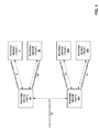
FIG. 4 is a block diagram illustrating an example of targeted neighbor connections that are established between multiple RP's and multiple FHR's. -
FIG. 5 is a block diagram illustrating example FHR's that establish targeted neighbor connections with a second RP after initial connections with a first RP have been closed. -
FIG. 6 is a conceptual diagram illustrating an example representation of a targeted hello message. -
FIG. 7 is a conceptual diagram illustrating an example representation of a register message. -
FIG. 8 is a flow diagram illustrating an example process that may be implemented by a routing device, such as by one or more of the RP's or FHR's shown inFIGS. 1-5 . - The techniques of the present disclosure provide a reliable targeted neighbor connection between a first routing device, such as a Rendezvous Point (RP), and a second routing device, such as a First Hop Router (FHR), through the exchange of periodic targeted hello messages using Protocol Independent Multicast (PIM), which may, in some instances, provide capability negotiation and discovery between the routing devices. These routing devices may be separated by one or more other intermediary routing devices, and therefore may be multiple hops away from each other. In one example, the techniques extend the concepts of Internet Engineering Task Force RFC 6559 ("A Reliable Transport Mechanism for PIM," Farinacci et al., March 2012, hereinafter "RFC 6559"), the entire content of which is incorporated herein by reference, to allow PIM registration state information to be sent over a reliable transport connection (e.g., targeted neighbor connection), which may potentially provide more scalability for certain multicast services like customer multicast, Internet-protocol television (IPTV), content replication between data centers, and the like.
- As one example, after sending an initial targeted hello message to the RP, the FHR listens for the RP to connect to the primary address of the FHR. Once the RP connects to the FHR, a targeted neighbor connection, which may comprise a reliable transport connection, is established between the two devices, where, in some cases, the FHR may have the active role, while the RP may have the passive role. The reliable connection may, in some instances, be maintained with keep-alive messages, as outlined in RFC 6559.
- Once this reliable connection is established, the FHR may start sending, to the RP, the source and group addresses of multicast streams that are active with the FHR. When any of these streams are later withdrawn, the FHR sends an update message to the RP to provide the source and group addresses associated with the streams that have been withdrawn. In this way, after a targeted neighbor connection is established between the FHR and the RP, the FHR is capable of updating the RP with its existing and active multicast streams. Subsequently, the FHR sends incremental updates about any changes to the status of these streams to the RP. In various examples, the messages sent by the FHR to the RP via the reliable connection may be referred to as reliable register messages. The implementation of register messages will be described in further detail below.
- The implementation of these techniques may, in some cases, provide a hard-state, reliable transport mechanism to supplement and/or replace the use of existing register messages in PIM Sparse Mode (SM) and potentially eliminate the need for the usage of register-stop or null-register messages between the RP and the FHR. In some examples, multiple different RP's that share the same anycast address may exchange targeted hello messages to establish a full mesh of targeted neighbor connections between these RP's. In addition, in certain examples, as will be described in further detail below, the techniques allow a FHR to discover the primary address of an RP operating in an Any Source Multicast (ASM) mode through the exchange of targeted hello messages.
-
FIG. 1 is a block diagram illustrating an example network 1 comprisingmultiple routing devices neighbor connection 24, which may comprise a reliable transport connection. Routingdevices example source devices example receiver device 6 are illustrated inFIG. 1 , although, in other examples, any number of source devices, receiver devices, and routing devices may be included in network 1. Examples of multicast traffic may include content for Internet Protocol Television (IPTV), desktop conferences, corporate broadcasts, music and video web casts, and other forms of multimedia content. -
Source devices routing device 8, and thereforerouting device 8 is referred to asFHR 8 in this example.Receiver device 6 is communicatively coupled torouting device 14, and thereforerouting device 14 is referred to as a Last Hop Receiver (LHR) in this example.Routing device 20 is configured to operate as a rendezvous point and is therefore referred to asRP 20. Although only oneFHR 8 and oneLHR 14 are shown inFIG. 1 , in other examples, any number of FHR's and LHR's may be communicatively coupled toRP 20 via one or more intermediary routing devices, such asrouting devices RP 20 is shown inFIG. 1 , in other examples, any number of RP's may be included in network 1 and communicatively coupled toFHR 8 andLHR 14. In some examples, one or more other RP's in network 1 may share an anycast address withRP 20. - Network 1 may be an enterprise network, a campus network, a service provider network, a home network, or another autonomous system. In any of these examples,
source devices receiver 6 may share data via network 1. In one example of network 1 as an enterprise network, each ofsource devices receiver device 6 may comprise one or more servers or employee computer terminals located in different regions of a single office location. In another example of network 1 as an enterprise network, each ofsource devices receiver device 6 may comprise a remote office location of a corporation such that enterprise network 1 may be extended across a public network, such as the Internet. Additionally, however, the techniques of this disclosure are applicable to other network types, both public and private. Examples of other network types include local area networks (LAN's), virtual local area networks (VLAN's), virtual private networks (VPN's), and the like. In some examples, network 1 may be coupled to one or more additional private or public networks, e.g., the Internet. In other examples, network 1 may comprise the Internet or another public network. In some cases, network 1 may comprise a multi-protocol label switching (MPLS) network. - Network 1 may utilize PIM as a multicast routing protocol to build distribution trees through network 1 to transport multicast traffic from
sources receiver 6 for particular multicast groups. PIM may operate in several different modes, such as Sparse Mode (SM), which may also support Any-Source Multicast (ASM).RP 20 is a routing device toward which multicast traffic fromsource devices receiver devices 6 rendezvous.RP 20 is used as a shared of a distribution tree for a range of multicast groups. In the illustrated example,RP 20,FHR 8,LHR 14, androuting devices source devices receiver device 6. This shared tree may include one or more paths that transport multicast traffic upstream, e.g., fromsource devices FHR 8 towardsRP 20, as well as downstream, e.g., away fromRP 20 towardsreceiver device 6 viaLHR 14. -
Receiver device 6 may subscribe to one or more multicast groups to receive multicast traffic.RP 20 may learn and store source addresses associated with source devices (e.g.,source devices 2, 4) for a certain range of multicast groups to whichreceiver device 6 belongs.RP 20,FHR 8,LHR 14, androuting devices source device 2, 4) of the multicast traffic. - As an example, when
LHR 14 detects thatreceiver device 6 is to receive traffic for a particular multicast group,LHR 14 may send a (*, G) join control message towardsRP 20. More specifically,LHR 14 may determine an address ofRP 20, which is responsible for the multicast group range that includes the particular multicast group.LHR 14 sends a (*, G) join control message becauseLHR 14 does not know the source of the multicast group. When an upstream routing device, e.g.,routing device 22, receives the (*, G) join control message,routing device 22 forwards the join control message further upstream towardsRP 20. In addition, (*, G) multicast tree state is instantiated in each routing device, e.g.,routing device 22, that the (*, G) join control message passes through on the way toRP 20. According to this process, routing devices may conceptually build a shared tree across network 1. Upon receipt,RP 20 processes the (*, G) join control message and may begin sending multicast traffic for the multicast group toLHR 14 upon its availability.LHR 14 provides the received multicast traffic toreceiver device 6. - As one example, PIM SM typically uses group state to natively forward multicast traffic for a multicast group from
source devices RP 20 for distribution to all devices in the shared tree that belong to the multicast group. For example,FHR 8 may forward multicast traffic upstream fromsource device RP 20 viarouting devices RP 20, in turn, forwards the multicast traffic downstream torouting device 22 andLHR 14, which have state for the multicast group, and towardsreceiver device 6. - In conventional PIM SM,
FHR 8 may tunnel multicast traffic fromsource devices RP 20 as control-plane payload traffic using PIM register mechanisms. Initially, the multicast traffic may comprise unicast-encapsulated data packets referred to as PIM register messages, but afterRP 20 has initiated source-specific joins towardssource devices devices source devices RP 20 viaFHR 8. To avoid processing two copies of individual data packets (e.g., encapsulated and non-encapsulated copies),RP 20 may send register-stop messages toFHR 8 to preventFHR 8 from unnecessarily sending the unicast-encapsulated data packets toRP 20. Upon receiving a register-stop message,FHR 8 may start a register-stop timer to maintain this state, and just before the timer expires,FHR 8 sends a null-register message toRP 20 to allowRP 20 to refresh the register-stop information atFHR 8. - This conventional approach, however, may have certain drawbacks. PIM register messages typically are not handled isolated in the data-plane alone or in the control-plane alone, as both functions are usually involved in the register mechanism. Additionally, register messages, register-stop messages, and null-register messages conventionally support carrying only the information about a single (S, G) stream. Thus, as one example, in a standard Ethernet frame, there may be information for a large number of (S, G) streams, and the conventional approach may cause
RP 20 to send a large volume of register-stop messages, as well ascause FHR 8 to send an equally large volume of null-register messages toRP 20. In addition, PIM register states are conventionally maintained as soft states that require constant refreshes (e.g., once every sixty seconds) fromFHR 8. This constant refresh can result in a large amount of unnecessary communication betweenFHR 8 andRP 20, particularly ifRP 20 serves a large number of streams. - Furthermore, as noted above,
FHR 8 may utilize a register-stop timer (e.g., timer value of five seconds from thetime FHR 8 sends a null-register message to RP 20). If a register-stop message fromRP 20 gets lost or delayed, and the register-stop timer expires,FHR 8 may begin forwarding encapsulated data packets toRP 20 as control-plane messages, which may not be desirable. In addition, the conventional PIM register mechanism may have certain potential security issues, as data register messages are sent as unicast messages fromFHR 8 toRP 20. - The techniques of the present disclosure introduce the concept of a targeted neighbor connection, which may comprise a reliable transport connection, between a first routing device, such as
RP 20, and a second routing device, such asFHR 8, with an improved message format (e.g., type-length-value, or TLV, based message format) through the implementation of targeted hello messages. These routing devices may be separated by one or more other intermediary routing devices, and therefore may be multiple hops away from each other. For example,RP 20 andFHR 8 may be separated by one or more routing devices, such asrouting devices FIG. 1 . In one example, the techniques allow multicast stream state information to be sent over such a targeted neighbor connection, which may provide more scalability for certain multicast services like customer multicast, Internet-protocol television (IPTV), content replication between data centers, and the like. - As shown in
FIG. 1 , a first routing device (e.g., RP 20) may exchange, with a second routing device (e.g., FHR 8) in network 1, targeted hello messages using a PIM protocol to establish a targetedneighbor connection 24 between the first routing device and the second routing device, where the first routing device exchanges the targeted hello messages with the second routing device via at least one intermediate routing device (e.g.,routing devices 16, 18), and where at least one of the first routing device or the second routing device comprises a rendezvous point (RP). These targeted hello messages may be similar to PIM hello messages defined in Network Working Group RFC 4601 ("Protocol Independent Multicast - Sparse Mode (PIM-SM): Protocol Specification (Revised)," Fenner et al., August 2006, hereinafter "RFC 4601"), the entire content of which is incorporated herein by reference. The targeted hello messages of the present disclosure, however, are not confined to the link level, but instead exist at an interface level and have a unicast address as the destination address and traverse multiple hops using unicast routing (e.g., viarouting device 16, 18) to reach a targeted hello neighbor (e.g.,RP 20 or FHR 8) identified by the destination address. The time-to-live value of these targeted hello messages may, in some cases, be set to a system default time-to-live value. - As will be described in further detail below, the first routing device may use targeted
neighbor connection 24 to process a register message that includes multiple multicast stream data elements. Each multicast stream data element identifies a source address and a group address that are collectively associated with a respective multicast stream, and each multicast stream data element further indicates whether the respective multicast stream is active or withdrawn. - For example,
RP 20 may receive, fromFHR 8, a first targeted hello message comprising a first unicast message that is addressed to a unicast address of RP 20 (e.g., any anycast address or a primary address of RP 20). In response to receiving the first targeted hello message,RP 20 sends, toFHR 8, a second targeted hello message to acknowledge receipt of the first targeted hello message. This second targeted hello message comprises a second unicast message that is addressed to a primary unicast address ofFHR 8. The exchange of these targeted hello messages establishes targetedneighbor connection 24 betweenRP 20 andFHR 8, whereFHR 8 may, in some cases, have the active role, andRP 20 may have the passive role. In some examples, targetedneighbor connection 24 may comprise a reliable transport connection (e.g., Transmission Control Protocol (TCP) or Stream Control Transmission (SCTP) protocol connection), as described in RFC 6559, cited above. The reliable transport mechanism, in some cases, can use either TCP or SCTP as the transport protocol. -
FHR 8 andRP 20 may also periodically "refresh" these targeted hello messages with one another, based on a refresh timer, to verify the continued presence of the targeted neighborship betweenFHR 8 andRP 20, as described in more detail below. - Once targeted
neighbor connection 24 has been established,FHR 8 may send one or more register messages for multicast streams toRP 20 using targetedneighbor connection 24. As noted above, and as will be described in more detail in reference toFIG. 2 , these register messages include multiple multicast stream data elements that each identify a source address and a group address that are collectively associated with a respective multicast stream. These register messages indicate, toRP 20, which multicast streams are active withFHR 8 and which streams have been withdrawn. Once targetedneighbor connection 24 has been established,FHR 8 is capable of sending a given register message toRP 20 indicating an entire list of one or more streams that are active withFHR 8, and an entire list of one or more streams that are withdrawn fromFHR 8. In various examples, all of the various register messages are sent byFHR 8 toRP 20 via targetedneighbor connection 24, which may comprise a reliable transport connection using TCP or SCTP (as non-limiting examples) for the transport protocol. Furthermore, in some cases, the reliable transport mechanism of targetedneighbor connection 24 may handle the retransmission of any register messages fromFHR 8 toRP 20, if needed (e.g., if any register messages are lost or corrupted during initial transmission from FHR 8). - For example, if a set of multicast streams have become active with
FHR 8,FHR 8 sends a register message toRP 20 with source and group addresses of these active streams, such thatRP 20 is able to update its state information for these active streams serviced byFHR 8. The state information maintained byRP 20 identifies a respective source address and group address for each active multicast stream. Subsequently, if any of these streams are withdrawn atFHR 8,FHR 8 sends an update register message toRP 20 indicating the source and group addresses of the streams that have been withdrawn. Upon receiving this updated message,RP 20 updates its state information (e.g., deletes the source and group addresses for the withdrawn streams from the state information). In this way, once targetedneighbor connection 24 is established,FHR 8 is capable of continuously updatingRP 20 with its existing and active multicast streams, as well as any streams that have been withdrawn. - As will also be described in further detail below in reference to
FIG. 4 , in some examples, multiple different RP's that share a same anycast address may exchange targeted hello messages to establish a full mesh targeted neighbor connections between these RP's. In addition, in certain examples, the techniques of the present disclosure allow a FHR (e.g., FHR 8) to discover the primary address of an RP (e.g., RP 20) operating in Any-Source Multicast (ASM) mode through the exchange of targeted hello messages. - The implementation of these techniques may, in some cases, provide a hard-state, reliable transport mechanism to supplement or even replace the use of conventional PIM SM register messages, register-stop messages, and/or null-register messages between
RP 20 andFHR 8. Instead,FHR 8 is configured to send register messages toRP 20 that each includes source and group address information for multiple multicast streams. The use of such messages may significantly reduce the volume of register messages betweenFHR 8 andRP 20, asFHR 8 takes the active role in the communication of such messages, and only sendsRP 20 new register messages in order to provide incremental updates about the status of individual streams (e.g., when certain streams have become active or withdrawn). However, as noted above, each individual register message may include source and group address information for multiple different streams. - With such an approach, in certain examples,
FHR 8 may avoid sending unicast- encapsulated multicast traffic data toRP 20, reducing the processing overhead and burden onRP 20 when routing such traffic to receivers (e.g., receiver device 6) in network 1. As a result, in various examples, the reliable transport mechanism may provide a form of congestion control to potentially avoid a flooding or overload of information betweenFHR 8 and RP 20 (e.g., register messages sent fromFHR 8 to RP 20). In addition, the reliable transport mechanism may help minimize packet loss betweenFHR 8 andRP 20 over targetedneighbor connection 24. - In addition, the techniques of the present disclosure may provide for improved security between
FHR 8 andRP 20 using targetedneighbor connection 24. As noted above, the reliable transport mechanism may help potentially avoid a flooding or overload of register messages or other information exchanged betweenFHR 8 andRP 20. - Furthermore, the present techniques may allow extensibility to achieve both intra- and interdomain source discovery. As shown in
FIG. 1 ,RP 20 andFHR 8 may establish targetedneighbor connection 24, andRP 20 may receive register messages fromFHR 8 regarding active and withdrawn streams forsource devices FHR 8. As also shown inFIGS. 4 and5 , FHR's may establish targeted neighbor connections with different RP's that share the same anycast address, and individual RP's may also establish targeted neighbor connections with other RP's that share the same anycast address. The FHR's may send register messages to any of these RP's regarding active and withdrawn streams for source devices coupled to these respective FHR's, and the FHR's may also discover the nearest or current anycast RP that services the given anycast address. In some instances, this may provide an automatic discovery process. -
FIG. 2 is a diagram illustrating an example message flow betweenRP 20 andFHR 8 ofFIG. 1 .FIG. 2 illustrates one non-limiting example of such a message flow. Initially, upon learning of an address ofRP 20,FHR 8 may send targetedhello message 30 toRP 20. Targetedhello message 30 is a unicast message that is addressed toRP 20. The primary source address of targetedhello message 30 is the address ofFHR 8, while the destination address, comprising a unicast address, is either the primary or anycast address ofRP 20. In some cases, targetedhello message 30 may further include information regarding one or more capabilities or features ofFHR 8.RP 20 may process targetedhello message 30 to discover such capabilities or features and/or negotiate one or more of these capabilities or features withFHR 8. - Upon receiving targeted
hello message 30,RP 20 may send targeted hello message 32 (reply) toFHR 8 to acknowledge receipt of targetedhello message 30 byRP 20. Targetedhello message 32 is a unicast message that is addressed toFHR 8. The primary source address of targetedhello message 32 is the primary address ofRP 20, while the destination address, comprising a unicast address, is the primary address ofFHR 8. In some instances, targetedhello message 32 may have a secondary source address, which may comprise an anycast address serviced byRP 20. In some cases, targetedhello message 32 may further include information regarding one or more capabilities or features ofRP 20.FHR 8 may process targetedhello message 32 to discover such capabilities or features ofRP 20 and/or negotiate one or more of these capabilities or features withRP 20 based on the capabilities or features supported byFHR 8. - As noted above, if
RP 20 is configured as an anycast RP and services an anycast address,FHR 8 may initially send targetedhello message 30 with a unicast destination address that is the anycast address ofRP 20. Upon receiving targetedhello message 32 fromRP 20,FHR 8 is able to further identify the primary address ofRP 20, whichFHR 8 may use when subsequently sending one or more register messages toRP 20. In such fashion,FHR 8 is capable of identifying the primary address of anycast RP 20 (e.g., to discover the nearest or current anycast RP that services the anycast address with whichFHR 8 may establish a targeted neighbor connection, namely RP 20). AfterFHR 8 andRP 20 exchange targetedhello messages neighbor connection 24 is established betweenFHR 8 andRP 20, whereFHR 8 may, in some cases, have the active role andRP 20 may have the passive role in the targeted neighborship.Targeted neighbor connection 24 may comprise a reliable transport connection. -
FHR 8 may maintain neighbor state information (e.g., neighbor state information 108 shown inFIG. 3 ) that includes information about all of its targeted neighbors. For example,FHR 8 may store the primary address and secondary address (e.g., anycast address) ofRP 20 in its neighbor state information, as well as any capabilities or features supported byRP 20 and/or negotiated betweenFHR 8 andRP 20. Similarly,RP 20 may maintain neighbor state information (e.g., neighbor state information 108) that includes information about all of its targeted neighbors. For example,RP 20 may store the primary address ofFHR 8 in its neighbor state information, as well as any capabilities or features supported byFHR 8 and/or negotiated betweenFHR 8 andRP 20. -
FHR 8 andRP 20 may also utilize refresh and hold timers when processing targeted hello messages (e.g., targetedhello message 30 and targeted hello message 32), which may be similar to timers outlined in RFC 4601, cited above. For example, in non-limiting cases, the default refresh time for targeted hello messages may be set to sixty seconds (e.g., 2 times the default link-level hello time outlined in RFC 4601), and the default hold time may be set to two hundred ten seconds (e.g., 3.5 times the default refresh time). In addition,FHR 8 andRP 20 may utilize keep-alive messages to check the liveliness of each other and targetedneighbor connection 24. In one example, these keep-alive messages may be similar to those described in RFC 6559, cited above, forreliable connection 24. - Regarding targeted
neighbor connection 24, connection loss or reachability loss could occur for one or more of the following reasons: (1) keep-alive message time out; (2) targeted neighbor loss (e.g., expiration of the hold timer for targeted hello messages); and/or (3) close of the connection. Upon detecting any of these conditions,FHR 8 and/orRP 20 may close targetedneighbor connection 24 and clear any corresponding state information (e.g., after a grace period), such thatFHR 8 andRP 20 may subsequently re-establish a new targeted neighbor connection and re-synchronize respective state information (e.g., respective neighbor state information 108 shown inFIG. 3 ) for the neighborship. As one note, shouldRP 20 and/orFHR 8 request termination of a targeted neighborship,RP 20 and/orFHR 8 may send a targeted hello message with a hold time as zero. In addition, ifRP 20 and/orFHR 8, at a particular point in time, determine that a reconnect or a capability renegotiation with the other device is warranted,RP 20 and/orFHR 8 may, in some examples, change the generation identifier (or "GenID," as referred to in RFC 6559 and/or RFC 4601) of the targeted hello messages, in order to reset states and reinitialize the targeted neighbor connection between the two devices. In these examples, a GenID may be included in each of the targeted hello messages exchanged between the two devices. - After targeted
neighbor connection 24 is established,FHR 8 may send one or more register messages for multicast streams toRP 20 using targetedneighbor connection 24 using the primary address ofRP 20. As shown in the example ofFIG. 2 ,FHR 8 sends one ormessages 34A-34N toRP 20. Each of these register messages include multiple multicast stream data elements that each identify a source address and a group address that are collectively associated with a respective multicast stream. Furthermore, these register messages indicate, toRP 20, which multicast streams are active withFHR 8 and which streams have been withdrawn. (Example formats of a register message and multicast stream data elements are described in more detail below in reference toFIG. 7 .) If a particular stream is active atFHR 8, the corresponding multicast stream data element of the register message may indicate that this particular stream is to be added to the stream state information maintained by RP 20 (e.g.,stream state information 109 shown inFIG. 3 ). If, however, a particular stream is withdrawn atFHR 8, the corresponding multicast stream data element of the register message may indicate that this particular stream is to be deleted from the stream state information maintained byRP 20. - For example, if a group of multicast streams have become active with
FHR 8,FHR 8 sendsregister message 34A toRP 20 with source and group addresses of these active streams, such thatRP 20 is able to update its stream state information for streams that are active atFHR 8 and that are serviced byRP 20. The stream state information maintained byRP 20 identifies a respective source address and group address for each active multicast stream. Subsequently, if any of these streams are withdrawn atFHR 8,FHR 8 may send another register message (e.g., registermessage 34N) toRP 20 indicating the source and group addresses of the streams that have been withdrawn. Upon receiving this updated message,RP 20 updates its stream state information (e.g., deletes the source and group addresses for the withdrawn streams). In this way, once targetedneighbor connection 24 is established,FHR 8 is capable of continuously updatingRP 20 with its existing and active multicast streams, as well as any streams that have been withdrawn. - Based upon the content of
register messages 34A-34N sent byFHR 8,RP 20 updates its stream state information for active multicast streams serviced byRP 20. The stream state information identifies a respective source address and group address for each active multicast stream, and may also identify the device from which the source and group address information is received (e.g., FHR 8). As one example, in a givenregister message 34A-34N received fromFHR 8, for each multicast stream that is indicated as active in the multicast stream data elements,RP 20 may add the respective source address and group address to its stream state information. On the other hand, for each multicast stream that is indicated as withdrawn in the multicast stream data elements of the given register message,RP 20 may remove the respective source address and group address its stream state information. - To provide a non-limiting example of the processing of
such register messages 34A-34N,FHR 8 may send RP 20 afirst register message 34A, via targetedneighbor connection 24, which includes a group of multicast stream data elements. In this example, the group of multicast stream data elements included inregister message 34A may be associated with a first group of multicast streams, namely STREAM 1,STREAM 2, and STREAM 3, which are each serviced byFHR 8. - For instance, a first multicast stream data element may identify a first source address S1 and a first group address G1 that are collectively associated with STREAM 1. This first multicast stream data element further indicates that STREAM 1 is active at FHR 8 (e.g., by indicating that S1 and G1 are to be added to the stream state information maintained by RP 20). Similarly, a second multicast stream data element identifies a second source address S2 and a second group address G2 that are collectively associated with
STREAM 2, and also indicates thatSTREAM 2 is active atFHR 8. A third multicast stream data element identifies a third source address S3 and a third group address G3 that are collectively associated with STREAM 3, and also indicates that STREAM 3 is active atFHR 8. - Upon receipt of
register message 34A,RP 20 may update its stream state information by adding, to the state information and based on the first multicast stream data element inregister message 34A, a first entry identifying the first source address S1 and the first group address G1 for STREAM 1. Similarly,RP 20 may add, based on the second multicast stream data element, a second entry identifying the second source address S2 and the second group address G2 forSTREAM 2, and may add, based on the third multicast stream data element, a third entry identifying the third source address S3 and the third group address G3 for STREAM 3. The first, second, and third entries in the stream state information ofRP 20 indicate that STREAM 1,STREAM 2, and STREAM 3, respectively, are active atFHR 8. - However, at a later point in time, if STREAM 1 becomes withdrawn at
FHR 8, but a new stream,STREAM 4, becomes active,FHR 8 may send aseparate register message 34N toRP 20 via targetedneighbor connection 24.Register message 34N includes a group of multicast stream data elements, where a first data element identifies the first source address S1 and the first group address G1 collectively associated with STREAM 1, and further indicates that STREAM 1 is now withdrawn at FHR 8 (e.g., by indicating that S1 and G1 are to be deleted from the stream state information maintained by RP 20).Register message 34N includes a second multicast stream data element that identifies a fourth source address S4 and a fourth group address G4 that are collectively associated withSTREAM 4, and also indicates thatSTREAM 4 is active at FHR 8 (e.g., by indicating that S4 and G4 are to be added to the stream state information maintained by RP 20). - Upon receipt of
register message 34N,RP 20 updates its stream state information by removing, from the state information and based on the first multicast stream data element inregister message 34N, the first entry identifying the first source address S1 and the first group address G1 for the STREAM 1. Additionally,RP 20 may add, based on the second multicast stream data element inregister message 34N, a fourth entry identifying the fourth source address S4 and the fourth group address G4 forSTREAM 4, indicating thatSTREAM 4 is active atFHR 8. In such fashion,FHR 8 is able to updateRP 20 with its existing, active multicast streams by sending incremental updates toRP 20. In response,RP 20 is able to update the stream state information for any multicast streams that are active atFHR 8 and that are serviced byRP 20. -
FIG. 3 is a block diagram illustrating anexample routing device 80, such as one of the routing devices shown inFIG. 1 orFIG. 2 . For example, any ofrouting devices device 80 illustrated inFIG. 3 . - In this example,
routing device 80 includesinterface cards 88A-88N ("IFC's 88") that receive multicast packets viaincoming links 90A-90N ("incoming links 90") and send multicast packets viaoutbound links 92A-92N ("outbound links 92"). IFC's 88 are typically coupled to links 90, 92 via a number of interface ports.Routing device 80 also includes acontrol unit 82 that determines routes of received packets and forwards the packets accordingly via IFC's 88. -
Control unit 82 may comprise arouting engine 84 and aforwarding engine 86. Routingengine 84 operates as the control plane for routingdevice 80 and includes an operating system that may provide a multi-tasking operating environment for execution of a number of concurrent processes. Routingengine 84 may implement one ormore routing protocols 102 to execute routing processes. For example,routing protocols 102 may include Border Gateway Protocol (BGP) 103, for exchanging routing information with other routing devices in a computer network (e.g., network 1) and for updatingrouting information 94. Routingengine 84 may also implement Interior Gateway Protocol (IGP) protocols, such as link state routing protocols Open Shortest Path First (OSPF) and/or Intermediate System-to-Intermediate System (IS-IS), for exchanging link state information with other routing. - Routing
information 94 may describe a topology of the computer network in whichrouting device 80 resides, and may also include routes through the shared trees in the computer network. Routinginformation 94 describes various routes within the computer network, and the appropriate next hops for each route, e.g., the neighboring routing devices along each of the routes. In the illustrated example, routinginformation 94 includes an incoming interface (IIF)list 95 and an outgoing interface (OIF)list 96 that indicates which of IFC's 88 are connected to neighboring routing devices in each route. For example, a given route may comprise a route for multicast traffic for a given multicast group G. In that example,IIF list 95 may include a list of interfaces to all downstream routing devices in the shared tree, andOIF list 96 may include a list of interfaces to upstream and downstream routing devices that have state for the multicast group. - In addition,
routing protocols 102 may includePIM 104, and specifically PIM SM, for routing multicast traffic through the computer network (e.g., network 1) with other routing devices conceptually formed into shared trees according to routinginformation 94 andstate information 98. Routingengine 84 may also implementPIM 104 to updatestate information 98.State information 98 may describe a current status of links between routing devices in the shared trees for the network. In the illustrated example,state information 98 includes group state information 99 that describes which neighboring routing devices belong to which multicast groups within the range for the shared tree. - Routing
engine 84 analyzes stored routinginformation 94 andstate information 98 and generates forwardinginformation 106 for forwardingengine 86.Forwarding information 106 may associate, for example, network destinations for certain multicast groups with specific next hops and corresponding IFC's 88 and physical output ports for output links 92.Forwarding information 106 may be a radix tree programmed into dedicated forwarding chips, a series of tables, a complex database, a link list, a radix tree, a database, a flat file, or various other data structures. In the illustrated example ofFIG. 3 , forwardinginformation 106 includes forwarding routes that include specific routes to forward multicast traffic for a given multicast group to neighboring routing devices. In general, when routingdevice 80 receives a multicast packet via one of inbound links 90,control unit 82 determines a next hop for the packet in accordance with forwardinginformation 106, and forwards the packet according to the next hop. - As shown in
FIG. 3 , and as described above in reference toFIG. 2 ,state information 98 also includes neighbor state information 108 and streamstate information 109.Routing device 80 may maintain neighbor state information 108 to include information about all of its targeted neighbors and targeted neighbor connections.Routing device 80 may store, in neighbor state information 108, the addresses of targeted neighbors with which it has established targeted neighbor connections, as well as any capability or feature information that is associated with each of such connections. For example, if routingdevice 80 comprises an FHR (e.g., FHR 8) that has established a targeted neighbor connection (e.g., targeted neighbor connection 24) with an RP (e.g., RP 20), routing device may store the primary address and any secondary address (e.g., anycast address) of the RP in neighbor state information 108, as well as any capabilities or features that are supported by the RP or that have been negotiated between the two devices. In general, neighbor state information 108 may include any such address and capability/feature information. -
State information 98 further includesstream state information 109, which includes information associated with active streams that are serviced by routingdevice 80.Routing device 80 maintains and updates streamstate information 109 in response to receiving register messages (e.g., registermessages 34A-34N shown inFIG. 2 ) from another routing device. For example,routing device 80 may receive a register message from a second routing device to indicate that a group of one or more multicast streams have become active at the second routing device. In such an example,routing device 80 may store the source and group addresses associated with each of these active streams instream state information 109. Streamstate information 109 identifies respective source and group addresses for each active multicast stream. In some instances,routing device 80 may also store, instream state information 109, the address (e.g., primary address) of the second routing device from which it has received the source and group address information. - Subsequently, if any of these streams are withdrawn at the second routing device,
routing device 80 may receive another register message from the second routing device specifying the source and group addresses of the streams that have been withdrawn. Upon receiving this updated message,routing device 80 updates its stream state information 109 (e.g., deletes the source and group addresses for the withdrawn streams). In this way, once a targeted neighbor connection is established withrouting device 80,routing device 80 is capable of continuously updating itsstream state information 109 to add source and group address information for existing and active multicast streams, and to delete source and group address information for any streams that have been withdrawn. - The architecture of
routing device 80 illustrated inFIG. 3 is shown by way of example only. The disclosure is not necessarily limited to this architecture. In other examples,routing device 80 may be configured in a variety of ways. In one example, some of the functionality ofcontrol unit 82 may be distributed within IFC's 88. In another example,control unit 82 may comprise a plurality of packet forwarding engines operated as slave routers. -
Control unit 82 may be implemented solely in software, or hardware, or may be implemented as a combination of software, hardware, or firmware. For example,control unit 82 may include one or more processors that execute software instructions. In that case, the various software modules ofcontrol unit 82 may comprise executable instructions stored on a computer-readable storage medium, such as computer memory or storage device. -
FIG. 4 is a block diagram illustrating an example of targeted neighbor connections that are established amongst multiple RP's and multiple FHR's. In the example ofFIG. 4 , two separate RP's, namelyRP 20 and RP 204, are each communicatively coupled to multiple different FHR's. In general, each RP may establish a respective targeted neighbor connection with one or more FHR's, and each RP may also be capable of establishing a respective targeted neighbor connection with one or more other RP's. In particular, in some examples, RP's may form targeted neighborships with each other if these RP's service the same anycast address, or if these RP's also act as FHR's for different multicast sources. In the examples ofFIGS. 4 and5 , each of the illustrated targeted neighbor connections may comprise a reliable transport connection. - Referring to
FIG. 4 ,RP 20 has established a targetedneighbor connection 24 withFHR 8 and a separate targetedneighbor connection 200 withFHR 30.RP 20 andFHR 8 may establish targetedneighbor connection 24 in a manner similar to that described above. In a similar fashion,RP 20 andFHR 30 may establish targetedneighbor connection 200. Each ofRP 20,FHR 8, andFHR 30 may each store neighbor state information (e.g., neighbor state information 108 shown inFIG. 3 ) associated with its respective targeted neighbors and targeted neighbor connections. For example,FHR 8 may maintain neighbor state information for targetedneighbor connection 24 to indicate a targeted neighborship withRP 20. This state information may include the primary address ofRP 20, any secondary (e.g., anycast) addresses ofRP 20, and any capabilities/features ofRP 20 and/orFHR 8 that are associated with targetedneighbor connection 24.FHR 30 may maintain similar neighbor state information for targetedneighbor connection 200. -
RP 20 may maintain neighbor state information regarding both targetedneighbor connection 24 withFHR 8 and targetedneighbor connection 200 withFHR 30. For targetedneighbor connection 24, the neighbor state information ofRP 20 may indicate a targeted neighborship withFHR 8 and may include the address ofFHR 8 and any capabilities/features ofRP 20 and/orFHR 8 that are associated with targetedneighbor connection 24.RP 20 may maintain similar stateinformation regarding FHR 30 for targetedneighbor connection 200. - As shown in
FIG. 4 , a second and separate RP 204 is communicatively coupled toFHR 206 andFHR 208. RP 204 has established a targetedneighbor connection 210 withFHR 206 and a separate targetedneighbor connection 212 withFHR 208 in a manner similar to that described above. Each of RP 204,FHR 206, andFHR 208 may also each store neighbor state information (e.g., neighbor state information 108 shown inFIG. 3 ) associated with its respective targeted neighbors and targeted neighbor connections in a manner similar to that described above.FHR 8,FHR 30,FHR 206, andFHR 208 may each be communicatively coupled to one or more source devices. (For example, as shown inFIG. 1 ,FHR 8 may be coupled tosource devices - In addition,
RP 20 and RP 204 may establish targetedneighbor connection 202, which is a connection between the two individual RP's. To do so,RP 20 and RP 204 may exchange targeted hello messages and each store state information about targetedneighbor connection 202, including the respective primary addresses ofRP 20 or RP 204 and potentially any capabilities/features ofRP 20 and RP 204 that are associated with targetedneighbor connection 202. - Furthermore,
RP 20 and RP 204 may also support PIM ASM and each serve the same anycast address. In general, an RP that serves an anycast address may be configured to store the primary addresses of other RP's serving the same anycast address, and these RP's may collectively form a full mesh of targeted neighborships. Thus, if bothRP 20 and RP 204 serve the same anycast address,RP 20 stores the primary address of RP 204, and RP 204 stores the primary address ofRP 20. By forming a targeted neighborship betweenRP 20 and RP 204, any ofFHR 8,FHR 30,FHR 206, and/orFHR 208 may establish targeted neighbor connections withRP 20 or RP 204, given thatRP 20 and RP 204 share the same anycast address. In addition, if any ofFHR 8,FHR 30,FHR 206, and/orFHR 208 has established a targeted neighbor connection with one ofRP 20 or RP 204, and this respective connection is lost (e.g., due to a failure or other issue),FHR 8,FHR 30,FHR 206, and/orFHR 208 may establish a targeted neighbor connection with the other one ofRP 20 or RP 204. - In the example of
FIG. 4 , each ofFHR 8,FHR 30,FHR 206, andFHR 208 may store the anycast address that is shared by bothRP 20 and RP 204. In certain examples, the techniques of the present disclosure allow any of these FHR's to discover the primary address ofRP 20 and/or RP 204 through the exchange of targeted hello messages. OnceFHR 8,FHR 30,FHR 206, and/orFHR 208 has received a targeted hello message fromRP 20 or RP 204 (e.g., targetedhello message 32 shown inFIG. 2 ) during establishment of a respective targeted neighbor connection,FHR 8,FHR 30,FHR 206, and/orFHR 208 may process the targeted hello message to identify the primary address ofRP 20 or RP 204, which is included in the targeted hello message. The anycast address and the primary address ofRP 20 and/or RP 204 may be stored in neighbor state information 108 (FIG. 2 ). As a result, at any point in time, any ofFHR 8,FHR 30,FHR 206, and/orFHR 208 may be able to discover the primary address of the nearest or current anycast RP (e.g., primary address ofRP 20 or RP 204), which services a given anycast address, through the exchange of targeted hello messages withRP 20 or RP 204. - In the particular example shown in
FIG. 4 , whereRP 20 and RP 204 share the same anycast address,RP 20 may be the nearest or current anycast RP forFHR 8 andFHR 30, as indicated by targetedneighbor connections FHR 206 andFHR 208, as indicated by targetedneighbor connections FIG. 5 , if a given targeted neighbor connection with one ofRP 20 or RP 204 is lost (e.g., due to failure or other issues), any ofFHR 8,FHR 30,FHR 206, and/orFHR 208 may exchange targeted hello messages with the other ofRP 20 or RP 204 to identify the primary address of this other RP, which may serve as the next nearest or current anycast RP having the same anycast address. - Once targeted
neighbor connections FHR 8 andFHR 30 may send register messages toRP 20 in a manner similar to that described above, such as in reference toFIG. 2 , andRP 20 may update its stream state information accordingly. For example,FHR 8 may send one or more register messages for multicast streams toRP 20 using targetedneighbor connection 24. Each of these register messages include multiple multicast stream data elements that each identify a source address and a group address that are collectively associated with a respective multicast stream. Furthermore, these register messages indicate, toRP 20, which multicast streams are active withFHR 8 and which streams have been withdrawn. Similarly,FHR 30 may sendRP 20 one or more register messages using targetedneighbor connection 200, where the register messages indicate which multicast streams atFHR 30 are active or withdrawn. Upon receiving these register messages,RP 20 updates its stream state information (e.g.,stream state information 109 shown inFIG. 3 ) to, e.g., add or delete source and group address information based on whether the respective stream is being added or deleted. - In addition, however, if
RP 20 is configured as an anycast RP,RP 20 transmits these state messages to any other RP's that have the same anycast address. Thus, if bothRP 20 and RP 204 have the same anycast address,RP 20 may transmit, to RP 204, any register messages it receives fromFHR 8 and/orFHR 30. Responsive to receiving such register messages, RP 204 may update its own stream state information for multicast streams associated withFHR 8 and/orFHR 30 based on the source and group address information contained in these messages. RP 204 will not retransmit the register messages received fromRP 20. In such fashion, RP 204 may use its targetedneighbor connection 202 withRP 20 as a portion of a full mesh of targeted neighbor connections among anycast RP's of the same anycast address to maintain stream state information about multicast streams associated withFHR 8 andFHR 30. - RP 204 may also receive register messages from
FHR 206 using targetedneighbor connection 210, and may also receive register messages fromFHR 208 using targetedneighbor connection 212, thereafter updating its stream state information accordingly. If bothRP 20 and RP 204 are configured as anycast RP's sharing the same anycast address, RP 204 may also transmit, toRP 20, any register messages it receives fromFHR 206 and/orFHR 208.RP 20 will not retransmit the register messages received from RP 204.RP 20 then updates its stream state information for the multicast streams associated withFHR 206 and/orFHR 208. Thus,RP 20 may use its targetedneighbor connection 202 with RP 204 as a portion of a full mesh of targeted neighbor connections among anycast RP's of the same anycast address to maintain stream state information about multicast streams associated withFHR 206 andFHR 208. - In some examples, an RP does not retransmit any register messages it has received from another anycast RP having the same anycast address. Thus, if, for example, both
RP 20 and RP 204 are configured as anycast RP's sharing the same anycast address, and RP 204 receives, fromRP 20, one or more register messages sent fromFHR 8 and/orFH 30, RP 204 does not retransmit these messages to another RP. Similarly, in this example,RP 20 does not retransmit any register messages it receives from RP 204. -
FIG. 5 is a block diagram illustrating example FHR's that establish targeted neighbor connections with a second RP after their initial connections with a first RP have been closed. For example, continuing with the example ofFIG. 4 , after initially establishing all of the initial targeted neighbor connections shown inFIG. 4 , it is possible that there may be an issue and/or failure withRP 20. In such a scenario, targetedneighbor connection 24 withFHR 8 and targetedneighbor connection 200 withFHR 30 may be closed byRP 20 or otherwise fail (e.g., upon closure of the connection, expiration of hello message hold and/or keep-alive timers). For example,FHR 8 may determine that its targetedneighbor connection 24 withRP 20 has been closed or otherwise failed, andFHR 30 may determine that its targetedneighbor connection 200 withRP 20 has been closed or otherwise failed. - Assuming, however, that
RP 20 and RP 204 had initially been configured as anycast RP's that share the same anycast address, bothFHR 8 andFHR 30 may establish new targeted neighbor connections with RP 204 as the next nearest anycast RP toFHR 8 andFHR 30, as shown inFIG. 5 . In its neighbor state information (e.g., neighbor state information 108 shown inFIG. 3 ), each ofFHR 8 andFHR 30 may have previously stored the anycast address ofRP 20. Upon closure of these targeted neighbor connections withRP 20,FHR 8 andFHR 30 may each clear out the stored state information corresponding to these connections, and may also utilize the stored anycast address ofRP 20, which is shared by RP 204, to establish new targeted connections with RP 204 and to store updated neighbor state information for these new connections. -
FHR 8 may exchange targeted hello messages with RP 204 to establish targeted neighbor connection 220, as shown inFIG. 5 , andFHR 30 may exchange targeted hello messages with RP 204 to establish targeted neighbor connection 222. Each ofFHR 8 andFHR 30 may use the anycast address of RP 204 when sending targeted hello messages to RP 204. During the exchange of these hello messages, bothFHR 8 andFHR 30 may receive and store the primary address of RP 204. Each ofFHR 8,FHR 30, and RP 204 may update its respective neighbor state information (e.g., neighbor state information 108) to store state information about the targeted neighborship betweenFHR 8 and RP 204 or betweenFHR 30 and RP 204. Because RP 204 shares the same anycast address asRP 20,FHR 8 andFHR 30 are each capable of identifying the primary address of RP 204 during the exchange of targeted hello messages (e.g., to discover the new, nearest or current anycast RP with whichFHR 8 andFHR 30 may establish targeted neighbor connections, namely RP 204). - Upon establishment of targeted neighbor connections 220 and 222,
FHR 8 andFHR 30 may respectively begin sending register messages to RP 204 (e.g., using the primary address of RP 204) regarding the status of any respective active or withdrawn multicast streams, similar to the techniques described above. Upon receiving these register messages, RP 204 updates its stream state information (e.g.,stream state information 109 shown inFIG. 3 ) regarding the state of multicast streams handled byFHR 8 andFHR 30, respectively. In such fashion, whenRP 20 and RP 204 are initially configured as anycast RP's that share the same anycast address,FHR 8 andFHR 30 may transition from a first RP to a second RP in the case of a failover or other issue, and may continue sending register messages to this second RP such that processing of multicast traffic may continue. -
FIG. 6 is a conceptual diagram illustrating an example representation of a targeted hello message. In some examples, the representation of a targeted hello message may be referred to as a type-length-value, or TLV, representation. The various targeted hello messages discussed throughout this disclosure, including targetedhello messages FIG. 2 , may have the format shown inFIG. 6 . As noted previously, targeted hello messages have a unicast address as the destination address, and they traverse multiple hops using unicast routing to reach a targeted hello neighbor identified by the destination address. - As shown in the example of
FIG. 6 , a targeted hello message may includefields Field 300 has a value that specifies the message type for a targeted hello message (e.g., value of thirty six for a targeted hello message type).Field 302 has a value that specifies the combined byte length offields fields -
Field 304 has a value specifying whether the sender of the targeted hello message requests having the role of a FHR in the targeted neighborship. In one example,field 304 is one bit in length and has a value of one (e.g., sender requests having role of a FHR) or zero (e.g., sender does not request having role of a FHR). -
Field 306 has a value specifying whether the sender of the targeted hello message is a device that is capable of taking the role of an RP in the targeted neighborship as per current states. In one example,field 306 is one bit in length and has a value of one (e.g., sender is capable of having role of an RP) or zero (e.g., sender is not capable of having role of an RP). If a particular RP serves an anycast RP address, this RP should, in some examples, set the value offield 306 to one. -
Field 308 may comprise a reserved field that is set to zero on transmission and ignored on receipt. In one example,field 308 is twenty six bits in length. - Finally,
field 310 may be provided for certain (e.g., experimental) uses, such as signaling experimental capabilities or features. For example, if a sender supports a particular capability or feature, it may set the value offield 310 accordingly. The routing devices that exchange targeted hello messages may use the information infield 310 of such messages to discover and/or negotiate one or more capabilities/features when establishing the targeted neighbor connection. In one example,field 310 is four bits in length. -
FIG. 7 is a conceptual diagram illustrating an example representation of a register message. In some examples, the representation of a register message may be referred to as a type-length-value, or TLV, representation. The various register messages discussed throughout this disclosure, includingregister messages 34A-34N shown inFIG. 2 , may have the format shown inFIG. 7 . - As shown in the example of
FIG. 7 , a register message may includefields Field 400 has a value that specifies the message type (e.g., value of three for IPv4 multicast streams, value of four for IPV6 multicast streams).Field 402 has a value that specifies the collective byte length offields fields -
Field 404 is a reserved field having a value that may, in some cases, merely be set to zero on transmission and ignored on receipt. In certain cases, however, the value offield 404 may be associated with properties that apply to the entire message.Field 406 may also be reserved for experimental use. In non-limiting examples,field 404 is twenty eight bits in length andfield 406 is four bits in length. - As discussed previously, each register message may include a plurality of multicast stream data elements. For instance, in the example of
FIG. 7 , the values offields fields -
Field 410A is a reserved field having a value that may, in some cases, merely be set to zero on transmission and ignored on receipt. In certain cases, however, the value offield 410A may be associated with properties that apply to multicast stream "A" and/or the source and group address included in multicast stream data element "A." In non-limiting examples,field 410A is thirty one bits in length. -
Field 408A designates whether source address 412A and group address 414A is to be added or deleted. In one example,field 408A is one bit in length that has a value of one (e.g., add) or zero (e.g., delete). When a FHR sets the value offield 408A to indicate thatsource address 412A and group address 414A are to be added, FHR has identified multicast stream "A" to be an active stream at the FHR, such that the RP may add the stream state information (e.g.,source address 412A and group address 414A) for this stream. On the other hand, if the value offield 408A indicates thatsource address 412A and group address 414A are to be deleted, FHR has identified multicast stream "A" to be withdrawn at the FHR, such that the RP may delete the stream state information (e.g.,source address 412A and group address 414A) for this stream. -
Field 412A specifies the source address associated with multicast stream "A." In non-limiting examples,field 412A has a byte length of four and a value corresponding to a source address of an IPv4 stream without any encoding, while in other examples,field 412A has a byte length of sixteen and a value corresponding to a source address of an IPv6 stream without any encoding. -
Field 414A specifies the group address associated with multicast stream "A." In non-limiting examples,field 414A has a byte length of four and a value corresponding to a group address of an IPv4 stream without any encoding, while in other examples,field 414A has a byte length of sixteen and a value corresponding to a group address of an IPv6 stream without any encoding. -
Fields fields -
FIG. 8 is a flow diagram illustrating an example process 50 that may be implemented by a routing device, such as by one or more of the RP's or FHR's shown inFIGS. 1-5 .Process 500 includesoperations - As shown in
FIG. 8 , a first routing device may exchange, with a second routing device, targeted hello messages using a PIM protocol to establish a targeted neighbor connection between the first routing device and the second routing device (502). The first routing device exchanges the targeted hello messages with the second routing device via at least one intermediate routing device (e.g.,routing device 16 and/or 18 shown inFIG. 1 ), and at least one of the first routing device or the second routing device comprises an RP. The first routing device uses the targeted neighbor connection with the second routing device to process a register message that includes multicast stream data elements (504). Each multicast stream data element identifies a source address and a group address that are collectively associated with a respective multicast stream, and each multicast stream data element further indicates whether the respective multicast stream is active or withdrawn. - For example, the first routing device may comprise the RP (e.g., RP 20) and the second routing device may comprise a FHR (e.g., FHR 8) that is coupled to at least one source device providing at least one multicast stream. In this example, the targeted neighbor connection comprises a reliable transport connection, and exchanging the targeted hello messages comprises receiving, by the RP and from the FHR, a first targeted hello message (e.g., targeted hello message 30) comprising a first unicast message that is addressed to the RP, and sending, by the RP and to the FHR, a second targeted hello message (targeted hello message 32) to acknowledge receipt of the first targeted hello message, where the second targeted hello message comprises a second unicast message that is addressed to the FHR, where a source address of the second targeted hello message comprises a primary address of the RP, and where a secondary address of the second targeted hello message comprises an anycast address of the RP. Processing the register message comprises receiving, by the RP and from the FHR using the targeted neighbor connection, the register message (e.g., register
message - The RP may update, based on the register message, state information (e.g., stream state information 109) for multicast streams that are active at the FHR and serviced by the RP, where the state information identifies a respective source address and group address for each active multicast stream. For instance, for each multicast stream that is indicated as active in the multicast stream data elements of the register message, the RP may update the state information at least by adding the respective source address and group address to the state information. For each multicast stream that is indicated as withdrawn in the multicast stream data elements of the register message, the RP may remove the respective source address and group address from the state information.
- To provide one non-limiting example, the RP may receive a first register message that includes a first plurality of multicast stream data elements. One of the first plurality of multicast stream data elements identifies a particular source address and a particular group address that are collectively associated with a particular multicast stream, and this multicast stream data element may further indicate that the particular multicast stream is active at the FHR. The RP may update the state information at least by adding, to the state information, an entry identifying the particular source address and the particular group address that are collectively associated with the particular multicast stream, the entry indicating that the particular multicast stream is active at the FHR.
- After receiving the first register message, the RP may receive, from the FHR using the targeted neighbor connection, a second register message that includes a second plurality of multicast stream data elements, where one of the second plurality of multicast stream data elements identifies the particular source address and the particular group address collectively associated with the particular multicast stream. This multicast stream data element may further indicate that the particular multicast stream is now withdrawn at the FHR. In response, the RP removes, from the state information, the entry identifying the particular source address and the particular group address for the particular multicast stream.
- In some examples, the RP comprises a first RP having the anycast address, and the targeted hello messages comprise a first plurality of targeted hello messages. The first RP may be an anycast RP that shares the same anycast address with a second RP (e.g., RP 204) having the same anycast address as the first RP. The first RP is capable of exchanging, with the second RP, a second plurality of hello messages to establish a targeted neighbor connection between the first RP and the second RP. Upon receiving a register message from the FHR, the first RP uses its targeted neighbor connection with the second RP to send, to the second RP, the register message received from the FHR. The second RP does not retransmit the register message received from the first RP.
- Referring back to
operations FIG. 8 , in some examples, the first routing device comprises a first hop router (FHR) coupled to at least one source device that provides at least one multicast stream, and the second routing device comprises the RP. In these examples, the targeted neighbor connection comprises a reliable transport connection, and exchanging the targeted hello messages comprises sending, by the FHR and to the RP, a first targeted hello message comprising a first unicast message that is addressed to the RP, and receiving, by the FHR and from the RP, a second targeted hello message to acknowledge receipt of the first targeted hello message, the second targeted hello message comprising a second unicast message that is addressed to the FHR. A source address of the second targeted hello message comprises a primary address of the RP, and a secondary address of the second targeted hello message comprises an anycast address of the RP. Processing the register message comprises sending, by the FHR and to the primary address of the RP using the targeted neighbor connection, the register message. If the first targeted hello message is addressed to an anycast address of the RP. In some cases, as described earlier, the FHR may send the first targeted hello message to the anycast address of the RP. - If the RP comprises a first RP that shares the same anycast address with a second RP, the plurality of targeted hello messages comprises a first plurality of targeted hello messages, at a given point in time, the FHR may determine that the targeted neighbor connection with the first RP has failed. In response, the FHR may exchange, with the second RP, a second plurality of targeted hello messages to establish a targeted neighbor connection between the FHR and the second RP, wherein the first RP and the second RP share the same anycast address.
- Furthermore, as previously described, the exchange of targeted hello messages may include discovering and/or negotiating one or more capabilities or features of the first and/or second routing device. These capabilities or features may be stored in the state information of each respective routing device (e.g., neighbor state information 108 shown in
FIG. 3 ). - Therefore, from a first perspective, there has been described that in one example, a method includes exchanging, by a first routing device and with a second routing device, targeted hello messages using a Protocol Independent Multicast (PIM) protocol to establish a targeted neighbor connection between the first routing device and the second routing device, wherein the first routing device exchanges the targeted hello messages with the second routing device via at least one intermediate routing device, and wherein at least one of the first or second routing device comprises a rendezvous point (RP). The example method further includes processing, by the first routing device using the targeted neighbor connection, a register message that includes multicast stream data elements, wherein each multicast stream data element identifies a source address and a group address that are collectively associated with a respective multicast stream, and wherein each multicast stream data element further indicates whether the respective multicast stream is active or withdrawn.
- Further examples of and consistent with the present teachings are set out in the followings numbered examples.
- Example 1: A method comprising: exchanging, by a first routing device and with a second routing device, a plurality of targeted hello messages using a Protocol Independent Multicast (PIM) protocol to establish a targeted neighbor connection between the first routing device and the second routing device, wherein the first routing device exchanges the plurality of targeted hello messages with the second routing device via at least one intermediate routing device, and wherein at least one of the first routing device or the second routing device comprises a rendezvous point (RP); and processing, by the first routing device using the targeted neighbor connection with the second routing device, a register message that includes a plurality of multicast stream data elements, wherein each multicast stream data element identifies a source address and a group address that are collectively associated with a respective multicast stream, and wherein each multicast stream data element further indicates whether the respective multicast stream is active or withdrawn.
- Example 2: The method of Example 1, wherein the targeted neighbor connection comprises a reliable transport connection, wherein the first routing device comprises the RP and the second routing device comprises a first hop router (FHR) coupled to at least one source device that provides at least one multicast stream, wherein exchanging the plurality of targeted hello messages comprises: receiving, by the RP and from the FHR, a first targeted hello message comprising a first unicast message that is addressed to the RP; and sending, by the RP and to the FHR, a second targeted hello message to acknowledge receipt of the first targeted hello message, wherein the second targeted hello message comprises a second unicast message that is addressed to the FHR, wherein a source address of the second targeted hello message comprises a primary address of the RP, and wherein a secondary address of the second targeted hello message comprises an anycast address of the RP; and wherein processing the register message comprises receiving, by the RP and from the FHR using the targeted neighbor connection, the register message, the register message being sent by the FHR to the primary address of the RP.
- Example 3: The method of Example 2, further comprising: updating, by the RP and based on the register message, state information for multicast streams that are active at the FHR and serviced by the RP, wherein the state information identifies a respective source address and group address for each active multicast stream.
- Example 4: The method of Example 3, wherein updating the state information comprises: for each multicast stream that is indicated as active in the plurality of multicast stream data elements of the register message, adding the respective source address and group address to the state information; and for each multicast stream that is indicated as withdrawn in the plurality of multicast stream data elements of the register message, removing the respective source address and group address from the state information.
- Example 5: The method of any of Examples 3-4, wherein receiving the register message comprises receiving a first register message that includes a first plurality of multicast stream data elements, wherein one of the first plurality of multicast stream data elements identifies a particular source address and a particular group address that are collectively associated with a particular multicast stream, the one of the first plurality of multicast stream data elements further indicating that the particular multicast stream is active at the FHR, and wherein updating the state information comprises adding, to the state information, an entry identifying the particular source address and the particular group address that are collectively associated with the particular multicast stream, the entry indicating that the particular multicast stream is active at the FHR.
- Example 6: The method of Example 5, further comprising: after receiving the first register message, receiving, by the RP and from the FHR using the targeted neighbor connection, a second register message that includes a second plurality of multicast stream data elements, wherein one of the second plurality of multicast stream data elements identifies the particular source address and the particular group address collectively associated with the particular multicast stream, the one of the second plurality of multicast stream data elements further indicating that the particular multicast stream is now withdrawn at the FHR; and removing, from the state information, the entry identifying the particular source address and the particular group address for the particular multicast stream.
- Example 7: The method of any of Examples 2-6, wherein the RP comprises a first RP having the anycast address, wherein the plurality of targeted hello messages comprises a first plurality of targeted hello messages, the method further comprising: exchanging, by the first RP and with a second RP having the same anycast address as the first RP, a second plurality of hello messages to establish a targeted neighbor connection between the first RP and the second RP; and sending, from the first RP and to the second RP, the register message received from the FHR, wherein the second RP does not retransmit the register message received from the first RP.
- Example 8: The method of any of Examples 1-7, wherein the targeted neighbor connection comprises a reliable transport connection, wherein the first routing device comprises a first hop router (FHR) coupled to at least one source device that provides at least one multicast stream, wherein the second routing device comprises the RP, wherein exchanging the plurality of targeted hello messages comprises: sending, by the FHR and to the RP, a first targeted hello message comprising a first unicast message that is addressed to the RP; and receiving, by the FHR and from the RP, a second targeted hello message to acknowledge receipt of the first targeted hello message, wherein the second targeted hello message comprises a second unicast message that is addressed to the FHR, wherein a source address of the second targeted hello message comprises a primary address of the RP, and wherein a secondary address of the second targeted hello message comprises an anycast address of the RP; and wherein processing the register message comprises sending, by the FHR and to the primary address of the RP using the targeted neighbor connection, the register message.
- Example 9: The method of Example 8, wherein sending the first targeted hello message comprises sending, by the FHR, the first targeted hello message to the anycast address of the RP.
- Example 10: The method of Example 9, wherein the RP comprises a first RP having the anycast address, wherein the plurality of targeted hello messages comprises a first plurality of targeted hello messages, and wherein the method further comprises: determining, by the FHR, that the targeted neighbor connection with the first RP has failed; and exchanging, by the FHR and with a second RP having the same anycast address as the first RP, a second plurality of targeted hello messages to establish a targeted neighbor connection between the FHR and the second RP, wherein the first RP and the second RP share the same anycast address.
- Example 11: The method of any of Examples 1-10, wherein exchanging the plurality of targeted hello messages comprises discovering one or more capabilities or features of the second routing device.
- Example 12: A first routing device, comprising: at least one processor, the at least one processor being configured to: exchange, with a second routing device, a plurality of targeted hello messages using a Protocol Independent Multicast (PIM) protocol to establish a targeted neighbor connection between the first routing device and the second routing device, wherein the first routing device exchanges the plurality of targeted hello messages with the second routing device via at least one intermediate routing device, and wherein at least one of the first routing device or the second routing device comprises a rendezvous point (RP); and process, using the targeted neighbor connection with the second routing device, a register message that includes a plurality of multicast stream data elements, wherein each multicast stream data element identifies a source address and a group address that are collectively associated with a respective multicast stream, and wherein each multicast stream data element further indicates whether the respective multicast stream is active or withdrawn.
- Example 13: The first routing device of Example 12, wherein the at least one processor is configured to perform the method of any of Examples 2-11.
- Example 14: A computer-readable storage medium comprising instructions that, when executed, cause at least one processor of a first routing device to perform operations comprising: exchanging, with a second routing device, a plurality of targeted hello messages using a Protocol Independent Multicast (PIM) protocol to establish a targeted neighbor connection between the first routing device and the second routing device, wherein the first routing device exchanges the plurality of targeted hello messages with the second routing device via at least one intermediate routing device, and wherein at least one of the first routing device or the second routing device comprises a rendezvous point (RP); and processing, using the targeted neighbor connection with the second routing device, a register message that includes a plurality of multicast stream data elements, wherein each multicast stream data element identifies a source address and a group address that are collectively associated with a respective multicast stream, and wherein each multicast stream data element further indicates whether the respective multicast stream is active or withdrawn.
- Example 15: The computer-readable storage medium of Example 14, wherein the instructions, when executed, cause the at least one processor of the first routing device to perform the method of any of Examples 2-11.
- The techniques described in this disclosure may be implemented, at least in part, in hardware, software, firmware or any combination thereof. For example, various aspects of the described techniques may be implemented within one or more processors, including one or more microprocessors, digital signal processors (DSP's), application specific integrated circuits (ASIC's), field programmable gate arrays (FPGA's), or any other equivalent integrated or discrete logic circuitry, as well as any combinations of such components. The term "processor" or "processing circuitry" may generally refer to any of the foregoing logic circuitry, alone or in combination with other logic circuitry, or any other equivalent circuitry. A control unit comprising hardware may also perform one or more of the techniques of this disclosure.
- Such hardware, software, and firmware may be implemented within the same device or within separate devices to support the various operations and functions described in this disclosure. In addition, any of the described units, modules or components may be implemented together or separately as discrete but interoperable logic devices. Depiction of different features as modules or units is intended to highlight different functional aspects and does not necessarily imply that such modules or units must be realized by separate hardware or software components. Rather, functionality associated with one or more modules or units may be performed by separate hardware or software components, or integrated within common or separate hardware or software components.
- The techniques described in this disclosure may also be embodied or encoded in a computer-readable medium, such as a computer-readable storage medium, containing instructions. Instructions embedded or encoded in a computer-readable medium may cause a programmable processor, or other processor, to perform one or more operations of a method, e.g., when the instructions are executed. Computer readable storage media, which is tangible and non-transitory, may include random access memory (RAM), read only memory (ROM), programmable read only memory (PROM), erasable programmable read only memory (EPROM), electronically erasable programmable read only memory (EEPROM), flash memory, a hard disk, a CD-ROM, a floppy disk, a cassette, magnetic media, optical media, or other computer-readable storage media. It should be understood that the term "computer-readable storage media" refers to non-transitory physical storage media as well as to transitory media such as signals, carrier waves, or other transient media.
- Various examples of the disclosure have been described. These and other examples are within the scope of the following claims.
Claims (15)
- A method comprising:exchanging, by a first routing device and with a second routing device, a plurality of targeted hello messages using a Protocol Independent Multicast (PIM) protocol to establish a targeted neighbor connection between the first routing device and the second routing device, wherein the first routing device exchanges the plurality of targeted hello messages with the second routing device via at least one intermediate routing device, and wherein at least one of the first routing device or the second routing device comprises a rendezvous point (RP); andprocessing, by the first routing device using the targeted neighbor connection with the second routing device, a register message that includes a plurality of multicast stream data elements, wherein each multicast stream data element identifies a source address and a group address that are collectively associated with a respective multicast stream, and wherein each multicast stream data element further indicates whether the respective multicast stream is active or withdrawn.
- The method of claim 1,
wherein the targeted neighbor connection comprises a reliable transport connection,
wherein the first routing device comprises the RP and the second routing device comprises a first hop router (FHR) coupled to at least one source device that provides at least one multicast stream,
wherein exchanging the plurality of targeted hello messages comprises:receiving, by the RP and from the FHR, a first targeted hello message comprising a first unicast message that is addressed to the RP; andsending, by the RP and to the FHR, a second targeted hello message to acknowledge receipt of the first targeted hello message, wherein the second targeted hello message comprises a second unicast message that is addressed to the FHR, wherein a source address of the second targeted hello message comprises a primary address of the RP, and wherein a secondary address of the second targeted hello message comprises an anycast address of the RP; andwherein processing the register message comprises receiving, by the RP and from the FHR using the targeted neighbor connection, the register message, the register message being sent by the FHR to the primary address of the RP. - The method of claim 2, further comprising:updating, by the RP and based on the register message, state information for multicast streams that are active at the FHR and serviced by the RP, wherein the state information identifies a respective source address and group address for each active multicast stream.
- The method of claim 3, wherein updating the state information comprises:for each multicast stream that is indicated as active in the plurality of multicast stream data elements of the register message, adding the respective source address and group address to the state information; andfor each multicast stream that is indicated as withdrawn in the plurality of multicast stream data elements of the register message, removing the respective source address and group address from the state information.
- The method of any of claims 3-4,
wherein receiving the register message comprises receiving a first register message that includes a first plurality of multicast stream data elements,
wherein one of the first plurality of multicast stream data elements identifies a particular source address and a particular group address that are collectively associated with a particular multicast stream, the one of the first plurality of multicast stream data elements further indicating that the particular multicast stream is active at the FHR, and
wherein updating the state information comprises adding, to the state information, an entry identifying the particular source address and the particular group address that are collectively associated with the particular multicast stream, the entry indicating that the particular multicast stream is active at the FHR. - The method of claim 5, further comprising:after receiving the first register message, receiving, by the RP and from the FHR using the targeted neighbor connection, a second register message that includes a second plurality of multicast stream data elements, wherein one of the second plurality of multicast stream data elements identifies the particular source address and the particular group address collectively associated with the particular multicast stream, the one of the second plurality of multicast stream data elements further indicating that the particular multicast stream is now withdrawn at the FHR; andremoving, from the state information, the entry identifying the particular source address and the particular group address for the particular multicast stream.
- The method of any of claims 2-6, wherein the RP comprises a first RP having the anycast address, wherein the plurality of targeted hello messages comprises a first plurality of targeted hello messages, the method further comprising:exchanging, by the first RP and with a second RP having the same anycast address as the first RP, a second plurality of hello messages to establish a targeted neighbor connection between the first RP and the second RP; andsending, from the first RP and to the second RP, the register message received from the FHR, wherein the second RP does not retransmit the register message received from the first RP.
- The method of any of claims 1-7,
wherein the targeted neighbor connection comprises a reliable transport connection,
wherein the first routing device comprises a first hop router (FHR) coupled to at least one source device that provides at least one multicast stream,
wherein the second routing device comprises the RP,
wherein exchanging the plurality of targeted hello messages comprises:sending, by the FHR and to the RP, a first targeted hello message comprising a first unicast message that is addressed to the RP; andreceiving, by the FHR and from the RP, a second targeted hello message to acknowledge receipt of the first targeted hello message, wherein the second targeted hello message comprises a second unicast message that is addressed to the FHR, wherein a source address of the second targeted hello message comprises a primary address of the RP, and wherein a secondary address of the second targeted hello message comprises an anycast address of the RP; andwherein processing the register message comprises sending, by the FHR and to the primary address of the RP using the targeted neighbor connection, the register message. - The method of claim 8, wherein sending the first targeted hello message comprises sending, by the FHR, the first targeted hello message to the anycast address of the RP.
- The method of claim 9, wherein the RP comprises a first RP having the anycast address, wherein the plurality of targeted hello messages comprises a first plurality of targeted hello messages, and wherein the method further comprises:determining, by the FHR, that the targeted neighbor connection with the first RP has failed; andexchanging, by the FHR and with a second RP having the same anycast address as the first RP, a second plurality of targeted hello messages to establish a targeted neighbor connection between the FHR and the second RP, wherein the first RP and the second RP share the same anycast address.
- The method of any of claims 1-10, wherein exchanging the plurality of targeted hello messages comprises discovering one or more capabilities or features of the second routing device.
- A first routing device, comprising:at least one processor, the at least one processor being configured to:exchange, with a second routing device, a plurality of targeted hello messages using a Protocol Independent Multicast (PIM) protocol to establish a targeted neighbor connection between the first routing device and the second routing device, wherein the first routing device exchanges the plurality of targeted hello messages with the second routing device via at least one intermediate routing device, and wherein at least one of the first routing device or the second routing device comprises a rendezvous point (RP); andprocess, using the targeted neighbor connection with the second routing device, a register message that includes a plurality of multicast stream data elements, wherein each multicast stream data element identifies a source address and a group address that are collectively associated with a respective multicast stream, and wherein each multicast stream data element further indicates whether the respective multicast stream is active or withdrawn.
- The first routing device of claim 12, wherein the at least one processor is configured to perform the method of any of claims 2-11.
- A computer-readable storage medium comprising instructions that, when executed, cause at least one processor of a first routing device to perform operations comprising:exchanging, with a second routing device, a plurality of targeted hello messages using a Protocol Independent Multicast (PIM) protocol to establish a targeted neighbor connection between the first routing device and the second routing device, wherein the first routing device exchanges the plurality of targeted hello messages with the second routing device via at least one intermediate routing device, and wherein at least one of the first routing device or the second routing device comprises a rendezvous point (RP); andprocessing, using the targeted neighbor connection with the second routing device, a register message that includes a plurality of multicast stream data elements, wherein each multicast stream data element identifies a source address and a group address that are collectively associated with a respective multicast stream, and wherein each multicast stream data element further indicates whether the respective multicast stream is active or withdrawn.
- The computer-readable storage medium of claim 14, wherein the instructions, when executed, cause the at least one processor of the first routing device to perform the method of any of claims 2-11.
Applications Claiming Priority (1)
| Application Number | Priority Date | Filing Date | Title |
|---|---|---|---|
| US14/576,830 US9660898B2 (en) | 2014-12-19 | 2014-12-19 | Enhanced protocol independent multicast source registration over a reliable transport |
Publications (2)
| Publication Number | Publication Date |
|---|---|
| EP3035592A1 true EP3035592A1 (en) | 2016-06-22 |
| EP3035592B1 EP3035592B1 (en) | 2018-11-07 |
Family
ID=54291026
Family Applications (1)
| Application Number | Title | Priority Date | Filing Date |
|---|---|---|---|
| EP15187317.1A Active EP3035592B1 (en) | 2014-12-19 | 2015-09-29 | Enhanced protocol independent multicast source registration over a reliable transport |
Country Status (3)
| Country | Link |
|---|---|
| US (1) | US9660898B2 (en) |
| EP (1) | EP3035592B1 (en) |
| CN (1) | CN105721310B (en) |
Families Citing this family (11)
| Publication number | Priority date | Publication date | Assignee | Title |
|---|---|---|---|---|
| US9843513B2 (en) | 2015-03-20 | 2017-12-12 | Juniper Networks, Inc. | Multicast flow overlay using registration over a reliable transport |
| US10942666B2 (en) * | 2017-10-13 | 2021-03-09 | Cisco Technology, Inc. | Using network device replication in distributed storage clusters |
| US10462233B2 (en) * | 2018-01-23 | 2019-10-29 | Charter Communications Operating, Llc | Protocol for anycast based discovery of local resources |
| CN108600110B (en) * | 2018-04-24 | 2020-12-29 | 新华三技术有限公司 | PIM message processing method and device |
| US11032186B2 (en) * | 2018-08-21 | 2021-06-08 | Vmware, Inc. | First hop router identification in distributed virtualized networks |
| US11405306B2 (en) | 2019-05-30 | 2022-08-02 | Cisco Technology, Inc. | Technique for dynamic discovery, update and propagation of multicast stream capabilities in a capability-aware network |
| US11601295B2 (en) | 2019-09-23 | 2023-03-07 | Juniper Networks, Inc. | Content delivery with reliable multicast using a redundant unicast overlay network |
| US20220094601A1 (en) * | 2020-09-23 | 2022-03-24 | Nokia Solutions And Networks Oy | Targeted neighbor discovery for border gateway protocol |
| US11102107B1 (en) * | 2020-10-12 | 2021-08-24 | Cisco Technology, Inc. | BIER overlay signaling enhancement |
| US11770465B2 (en) * | 2020-10-20 | 2023-09-26 | Nokia Solutions And Networks Oy | Supporting multiple transport options for border gateway protocol |
| US11658903B2 (en) * | 2021-04-06 | 2023-05-23 | Arista Networks, Inc. | Network device route programming |
Family Cites Families (10)
| Publication number | Priority date | Publication date | Assignee | Title |
|---|---|---|---|---|
| US8582468B2 (en) * | 2006-03-13 | 2013-11-12 | Cisco Technology, Inc. | System and method for providing packet proxy services across virtual private networks |
| WO2007122503A2 (en) * | 2006-04-24 | 2007-11-01 | Nokia Corporation | Reliable multicast/broadcast in a wireless network |
| WO2009068093A1 (en) * | 2007-11-28 | 2009-06-04 | Telefonaktiebolaget Lm Ericsson (Publ) | Multicast source mobility |
| US7969981B2 (en) | 2008-09-02 | 2011-06-28 | Cisco Technology, Inc. | System and method for multicasting in an internet protocol virtual private network environment |
| US8503289B2 (en) * | 2010-03-19 | 2013-08-06 | Brocade Communications Systems, Inc. | Synchronizing multicast information for linecards |
| US8638787B2 (en) * | 2010-05-20 | 2014-01-28 | Cisco Technology, Inc. | Multicast hello on demand |
| US20130188638A1 (en) * | 2012-01-23 | 2013-07-25 | Cisco Technology, Inc. | Multicast Source Registration |
| US9325605B2 (en) * | 2013-03-15 | 2016-04-26 | Cisco Technology, Inc. | On-demand boot strap router source announcements |
| CN103475665B (en) * | 2013-09-18 | 2017-07-04 | 新华三技术有限公司 | A kind of method and device for distinguishing Protocol Independent Multicast agreement multicast set type |
| CN103595645B (en) * | 2013-11-19 | 2017-03-15 | 杭州华三通信技术有限公司 | A kind of multicast flow management method and device |
-
2014
- 2014-12-19 US US14/576,830 patent/US9660898B2/en active Active
-
2015
- 2015-09-28 CN CN201510628736.8A patent/CN105721310B/en active Active
- 2015-09-29 EP EP15187317.1A patent/EP3035592B1/en active Active
Non-Patent Citations (5)
| Title |
|---|
| FARINACCI IJ WIJNANDS S VENAAS CISCO SYSTEMS M NAPIERALA AT&T LABS D: "A Reliable Transport Mechanism for PIM; rfc6559.txt", A RELIABLE TRANSPORT MECHANISM FOR PIM; RFC6559.TXT, INTERNET ENGINEERING TASK FORCE, IETF; STANDARD, INTERNET SOCIETY (ISOC) 4, RUE DES FALAISES CH- 1205 GENEVA, SWITZERLAND, 26 March 2012 (2012-03-26), pages 1 - 29, XP015081478 * |
| FENNER AT&T LABS-RESEARCH M HANDLEY UCL H HOLBROOK ARASTRA I KOUVELAS CISCO B: "Protocol Independent Multicast - Sparse Mode (PIM-SM): Protocol Specification (Revised); rfc4601.txt", 5. JCT-VC MEETING; 96. MPEG MEETING; 16-3-2011 - 23-3-2011; GENEVA; (JOINT COLLABORATIVE TEAM ON VIDEO CODING OF ISO/IEC JTC1/SC29/WG11 AND ITU-T SG.16 ); URL: HTTP://WFTP3.ITU.INT/AV-ARCH/JCTVC-SITE/, INTERNET ENGINEERING TASK FORCE, IETF, CH, 1 August 2006 (2006-08-01), XP015047366, ISSN: 0000-0003 * |
| MACKER J ET AL: "Simplified Multicast Forwarding; rfc6621.txt", SIMPLIFIED MULTICAST FORWARDING; RFC6621.TXT, INTERNET ENGINEERING TASK FORCE, IETF; STANDARD, INTERNET SOCIETY (ISOC) 4, RUE DES FALAISES CH- 1205 GENEVA, SWITZERLAND, 18 May 2012 (2012-05-18), pages 1 - 55, XP015081535 * |
| SARIKAYA HUAWEI USA H JI CHINA TELECOM B: "Multicast Support for Mapping of Address and Port Protocol and Light Weight 4over6; draft-sarikaya-softwire-map-multicast-03.txt", MULTICAST SUPPORT FOR MAPPING OF ADDRESS AND PORT PROTOCOL AND LIGHT WEIGHT 4OVER6; DRAFT-SARIKAYA-SOFTWIRE-MAP-MULTICAST-03.TXT, INTERNET ENGINEERING TASK FORCE, IETF; STANDARDWORKINGDRAFT, INTERNET SOCIETY (ISOC) 4, RUE DES FALAISES CH- 1205 GENEVA, 29 September 2014 (2014-09-29), pages 1 - 25, XP015101886 * |
| SERBEST INTERNET ENGINEERING TASK FORCE SBC RAY QIU VENU HEMIGE ALCATEL ROB NATH RIVERSTONE Y: "Supporting IP Multicast over VPLS; draft-serbest-l2vpn-vpls-mcast-03.txt", 5. JCT-VC MEETING; 96. MPEG MEETING; 16-3-2011 - 23-3-2011; GENEVA; (JOINT COLLABORATIVE TEAM ON VIDEO CODING OF ISO/IEC JTC1/SC29/WG11 AND ITU-T SG.16 ); URL: HTTP://WFTP3.ITU.INT/AV-ARCH/JCTVC-SITE/, INTERNET ENGINEERING TASK FORCE, IETF, CH, no. 3, 1 July 2005 (2005-07-01), XP015040134, ISSN: 0000-0004 * |
Also Published As
| Publication number | Publication date |
|---|---|
| CN105721310B (en) | 2020-07-24 |
| EP3035592B1 (en) | 2018-11-07 |
| US20160182358A1 (en) | 2016-06-23 |
| CN105721310A (en) | 2016-06-29 |
| US9660898B2 (en) | 2017-05-23 |
Similar Documents
| Publication | Publication Date | Title |
|---|---|---|
| US10476793B2 (en) | Multicast flow overlay using registration over a reliable transport | |
| EP3035592B1 (en) | Enhanced protocol independent multicast source registration over a reliable transport | |
| US9832290B2 (en) | Protocol independent multicast register optimization | |
| US20200245206A1 (en) | Bit indexed explicit replication based multicast for locator identifier separation protocol | |
| US9838303B2 (en) | PIM source discovery by last hop router | |
| US8717934B2 (en) | Multicast source move detection for layer-2 interconnect solutions | |
| US9860110B2 (en) | Multicast only fast re-route over remote loop-free alternate backup path | |
| US10104139B2 (en) | Selectively signaling selective tunnels in multicast VPNs | |
| US9288067B2 (en) | Adjacency server for virtual private networks | |
| WO2017114153A1 (en) | Service function chaining (sfc) communication method and device | |
| WO2021031648A1 (en) | Evpn and vpls coexistence method, apparatus, and system | |
| US9998292B2 (en) | PIM source discovery by last hop router on shared tree | |
| CN102638389A (en) | Redundancy backup method and system of TRILL (Transparent Interconnection over Lots of Links) network | |
| CN112543107B (en) | Content delivery with reliable multicast using redundant unicast overlay networks | |
| WO2022021818A1 (en) | Method and device for processing data message, storage medium, and electronic device | |
| EP3907940B1 (en) | Ingress replication procedures to facilitate migration to segment routing technology in a computer network | |
| US9948474B2 (en) | Network system, packet transmission apparatus, packet transmission method, and recording medium recording information processing program | |
| US11323364B2 (en) | Ingress replication procedures to facilitate migration to segment routing technology in a computer network | |
| JP2004282177A (en) | Data relaying method, data relaying apparatus, and data relaying system employing the apparatus |
Legal Events
| Date | Code | Title | Description |
|---|---|---|---|
| PUAI | Public reference made under article 153(3) epc to a published international application that has entered the european phase |
Free format text: ORIGINAL CODE: 0009012 |
|
| AK | Designated contracting states |
Kind code of ref document: A1 Designated state(s): AL AT BE BG CH CY CZ DE DK EE ES FI FR GB GR HR HU IE IS IT LI LT LU LV MC MK MT NL NO PL PT RO RS SE SI SK SM TR |
|
| AX | Request for extension of the european patent |
Extension state: BA ME |
|
| STAA | Information on the status of an ep patent application or granted ep patent |
Free format text: STATUS: REQUEST FOR EXAMINATION WAS MADE |
|
| 17P | Request for examination filed |
Effective date: 20161122 |
|
| RBV | Designated contracting states (corrected) |
Designated state(s): AL AT BE BG CH CY CZ DE DK EE ES FI FR GB GR HR HU IE IS IT LI LT LU LV MC MK MT NL NO PL PT RO RS SE SI SK SM TR |
|
| REG | Reference to a national code |
Ref country code: DE Ref legal event code: R079 Ref document number: 602015019419 Country of ref document: DE Free format text: PREVIOUS MAIN CLASS: H04L0012180000 Ipc: H04L0029120000 |
|
| GRAP | Despatch of communication of intention to grant a patent |
Free format text: ORIGINAL CODE: EPIDOSNIGR1 |
|
| STAA | Information on the status of an ep patent application or granted ep patent |
Free format text: STATUS: GRANT OF PATENT IS INTENDED |
|
| RIC1 | Information provided on ipc code assigned before grant |
Ipc: H04L 12/18 20060101ALI20180313BHEP Ipc: H04L 12/741 20130101ALI20180313BHEP Ipc: H04L 12/701 20130101ALI20180313BHEP Ipc: H04L 12/751 20130101ALI20180313BHEP Ipc: H04L 29/12 20060101AFI20180313BHEP Ipc: H04L 12/761 20130101ALI20180313BHEP |
|
| INTG | Intention to grant announced |
Effective date: 20180413 |
|
| GRAJ | Information related to disapproval of communication of intention to grant by the applicant or resumption of examination proceedings by the epo deleted |
Free format text: ORIGINAL CODE: EPIDOSDIGR1 |
|
| STAA | Information on the status of an ep patent application or granted ep patent |
Free format text: STATUS: REQUEST FOR EXAMINATION WAS MADE |
|
| GRAR | Information related to intention to grant a patent recorded |
Free format text: ORIGINAL CODE: EPIDOSNIGR71 |
|
| GRAS | Grant fee paid |
Free format text: ORIGINAL CODE: EPIDOSNIGR3 |
|
| STAA | Information on the status of an ep patent application or granted ep patent |
Free format text: STATUS: GRANT OF PATENT IS INTENDED |
|
| INTC | Intention to grant announced (deleted) | ||
| GRAA | (expected) grant |
Free format text: ORIGINAL CODE: 0009210 |
|
| STAA | Information on the status of an ep patent application or granted ep patent |
Free format text: STATUS: THE PATENT HAS BEEN GRANTED |
|
| INTG | Intention to grant announced |
Effective date: 20180906 |
|
| AK | Designated contracting states |
Kind code of ref document: B1 Designated state(s): AL AT BE BG CH CY CZ DE DK EE ES FI FR GB GR HR HU IE IS IT LI LT LU LV MC MK MT NL NO PL PT RO RS SE SI SK SM TR |
|
| REG | Reference to a national code |
Ref country code: GB Ref legal event code: FG4D |
|
| REG | Reference to a national code |
Ref country code: CH Ref legal event code: EP Ref country code: AT Ref legal event code: REF Ref document number: 1063465 Country of ref document: AT Kind code of ref document: T Effective date: 20181115 |
|
| REG | Reference to a national code |
Ref country code: DE Ref legal event code: R096 Ref document number: 602015019419 Country of ref document: DE |
|
| REG | Reference to a national code |
Ref country code: IE Ref legal event code: FG4D |
|
| REG | Reference to a national code |
Ref country code: NL Ref legal event code: MP Effective date: 20181107 |
|
| REG | Reference to a national code |
Ref country code: LT Ref legal event code: MG4D |
|
| REG | Reference to a national code |
Ref country code: AT Ref legal event code: MK05 Ref document number: 1063465 Country of ref document: AT Kind code of ref document: T Effective date: 20181107 |
|
| PG25 | Lapsed in a contracting state [announced via postgrant information from national office to epo] |
Ref country code: FI Free format text: LAPSE BECAUSE OF FAILURE TO SUBMIT A TRANSLATION OF THE DESCRIPTION OR TO PAY THE FEE WITHIN THE PRESCRIBED TIME-LIMIT Effective date: 20181107 Ref country code: LV Free format text: LAPSE BECAUSE OF FAILURE TO SUBMIT A TRANSLATION OF THE DESCRIPTION OR TO PAY THE FEE WITHIN THE PRESCRIBED TIME-LIMIT Effective date: 20181107 Ref country code: HR Free format text: LAPSE BECAUSE OF FAILURE TO SUBMIT A TRANSLATION OF THE DESCRIPTION OR TO PAY THE FEE WITHIN THE PRESCRIBED TIME-LIMIT Effective date: 20181107 Ref country code: AT Free format text: LAPSE BECAUSE OF FAILURE TO SUBMIT A TRANSLATION OF THE DESCRIPTION OR TO PAY THE FEE WITHIN THE PRESCRIBED TIME-LIMIT Effective date: 20181107 Ref country code: BG Free format text: LAPSE BECAUSE OF FAILURE TO SUBMIT A TRANSLATION OF THE DESCRIPTION OR TO PAY THE FEE WITHIN THE PRESCRIBED TIME-LIMIT Effective date: 20190207 Ref country code: NO Free format text: LAPSE BECAUSE OF FAILURE TO SUBMIT A TRANSLATION OF THE DESCRIPTION OR TO PAY THE FEE WITHIN THE PRESCRIBED TIME-LIMIT Effective date: 20190207 Ref country code: LT Free format text: LAPSE BECAUSE OF FAILURE TO SUBMIT A TRANSLATION OF THE DESCRIPTION OR TO PAY THE FEE WITHIN THE PRESCRIBED TIME-LIMIT Effective date: 20181107 Ref country code: IS Free format text: LAPSE BECAUSE OF FAILURE TO SUBMIT A TRANSLATION OF THE DESCRIPTION OR TO PAY THE FEE WITHIN THE PRESCRIBED TIME-LIMIT Effective date: 20190307 Ref country code: ES Free format text: LAPSE BECAUSE OF FAILURE TO SUBMIT A TRANSLATION OF THE DESCRIPTION OR TO PAY THE FEE WITHIN THE PRESCRIBED TIME-LIMIT Effective date: 20181107 |
|
| PG25 | Lapsed in a contracting state [announced via postgrant information from national office to epo] |
Ref country code: AL Free format text: LAPSE BECAUSE OF FAILURE TO SUBMIT A TRANSLATION OF THE DESCRIPTION OR TO PAY THE FEE WITHIN THE PRESCRIBED TIME-LIMIT Effective date: 20181107 Ref country code: NL Free format text: LAPSE BECAUSE OF FAILURE TO SUBMIT A TRANSLATION OF THE DESCRIPTION OR TO PAY THE FEE WITHIN THE PRESCRIBED TIME-LIMIT Effective date: 20181107 Ref country code: PT Free format text: LAPSE BECAUSE OF FAILURE TO SUBMIT A TRANSLATION OF THE DESCRIPTION OR TO PAY THE FEE WITHIN THE PRESCRIBED TIME-LIMIT Effective date: 20190307 Ref country code: GR Free format text: LAPSE BECAUSE OF FAILURE TO SUBMIT A TRANSLATION OF THE DESCRIPTION OR TO PAY THE FEE WITHIN THE PRESCRIBED TIME-LIMIT Effective date: 20190208 Ref country code: RS Free format text: LAPSE BECAUSE OF FAILURE TO SUBMIT A TRANSLATION OF THE DESCRIPTION OR TO PAY THE FEE WITHIN THE PRESCRIBED TIME-LIMIT Effective date: 20181107 Ref country code: SE Free format text: LAPSE BECAUSE OF FAILURE TO SUBMIT A TRANSLATION OF THE DESCRIPTION OR TO PAY THE FEE WITHIN THE PRESCRIBED TIME-LIMIT Effective date: 20181107 |
|
| PG25 | Lapsed in a contracting state [announced via postgrant information from national office to epo] |
Ref country code: CZ Free format text: LAPSE BECAUSE OF FAILURE TO SUBMIT A TRANSLATION OF THE DESCRIPTION OR TO PAY THE FEE WITHIN THE PRESCRIBED TIME-LIMIT Effective date: 20181107 Ref country code: IT Free format text: LAPSE BECAUSE OF FAILURE TO SUBMIT A TRANSLATION OF THE DESCRIPTION OR TO PAY THE FEE WITHIN THE PRESCRIBED TIME-LIMIT Effective date: 20181107 Ref country code: DK Free format text: LAPSE BECAUSE OF FAILURE TO SUBMIT A TRANSLATION OF THE DESCRIPTION OR TO PAY THE FEE WITHIN THE PRESCRIBED TIME-LIMIT Effective date: 20181107 Ref country code: PL Free format text: LAPSE BECAUSE OF FAILURE TO SUBMIT A TRANSLATION OF THE DESCRIPTION OR TO PAY THE FEE WITHIN THE PRESCRIBED TIME-LIMIT Effective date: 20181107 |
|
| REG | Reference to a national code |
Ref country code: DE Ref legal event code: R097 Ref document number: 602015019419 Country of ref document: DE |
|
| PG25 | Lapsed in a contracting state [announced via postgrant information from national office to epo] |
Ref country code: EE Free format text: LAPSE BECAUSE OF FAILURE TO SUBMIT A TRANSLATION OF THE DESCRIPTION OR TO PAY THE FEE WITHIN THE PRESCRIBED TIME-LIMIT Effective date: 20181107 Ref country code: SM Free format text: LAPSE BECAUSE OF FAILURE TO SUBMIT A TRANSLATION OF THE DESCRIPTION OR TO PAY THE FEE WITHIN THE PRESCRIBED TIME-LIMIT Effective date: 20181107 Ref country code: SK Free format text: LAPSE BECAUSE OF FAILURE TO SUBMIT A TRANSLATION OF THE DESCRIPTION OR TO PAY THE FEE WITHIN THE PRESCRIBED TIME-LIMIT Effective date: 20181107 Ref country code: RO Free format text: LAPSE BECAUSE OF FAILURE TO SUBMIT A TRANSLATION OF THE DESCRIPTION OR TO PAY THE FEE WITHIN THE PRESCRIBED TIME-LIMIT Effective date: 20181107 |
|
| PLBE | No opposition filed within time limit |
Free format text: ORIGINAL CODE: 0009261 |
|
| STAA | Information on the status of an ep patent application or granted ep patent |
Free format text: STATUS: NO OPPOSITION FILED WITHIN TIME LIMIT |
|
| 26N | No opposition filed |
Effective date: 20190808 |
|
| PG25 | Lapsed in a contracting state [announced via postgrant information from national office to epo] |
Ref country code: SI Free format text: LAPSE BECAUSE OF FAILURE TO SUBMIT A TRANSLATION OF THE DESCRIPTION OR TO PAY THE FEE WITHIN THE PRESCRIBED TIME-LIMIT Effective date: 20181107 |
|
| PG25 | Lapsed in a contracting state [announced via postgrant information from national office to epo] |
Ref country code: TR Free format text: LAPSE BECAUSE OF FAILURE TO SUBMIT A TRANSLATION OF THE DESCRIPTION OR TO PAY THE FEE WITHIN THE PRESCRIBED TIME-LIMIT Effective date: 20181107 |
|
| PG25 | Lapsed in a contracting state [announced via postgrant information from national office to epo] |
Ref country code: MC Free format text: LAPSE BECAUSE OF FAILURE TO SUBMIT A TRANSLATION OF THE DESCRIPTION OR TO PAY THE FEE WITHIN THE PRESCRIBED TIME-LIMIT Effective date: 20181107 |
|
| REG | Reference to a national code |
Ref country code: CH Ref legal event code: PL |
|
| PG25 | Lapsed in a contracting state [announced via postgrant information from national office to epo] |
Ref country code: LU Free format text: LAPSE BECAUSE OF NON-PAYMENT OF DUE FEES Effective date: 20190929 Ref country code: IE Free format text: LAPSE BECAUSE OF NON-PAYMENT OF DUE FEES Effective date: 20190929 Ref country code: CH Free format text: LAPSE BECAUSE OF NON-PAYMENT OF DUE FEES Effective date: 20190930 Ref country code: LI Free format text: LAPSE BECAUSE OF NON-PAYMENT OF DUE FEES Effective date: 20190930 |
|
| REG | Reference to a national code |
Ref country code: BE Ref legal event code: MM Effective date: 20190930 |
|
| PG25 | Lapsed in a contracting state [announced via postgrant information from national office to epo] |
Ref country code: BE Free format text: LAPSE BECAUSE OF NON-PAYMENT OF DUE FEES Effective date: 20190930 |
|
| PG25 | Lapsed in a contracting state [announced via postgrant information from national office to epo] |
Ref country code: CY Free format text: LAPSE BECAUSE OF FAILURE TO SUBMIT A TRANSLATION OF THE DESCRIPTION OR TO PAY THE FEE WITHIN THE PRESCRIBED TIME-LIMIT Effective date: 20181107 |
|
| PG25 | Lapsed in a contracting state [announced via postgrant information from national office to epo] |
Ref country code: MT Free format text: LAPSE BECAUSE OF FAILURE TO SUBMIT A TRANSLATION OF THE DESCRIPTION OR TO PAY THE FEE WITHIN THE PRESCRIBED TIME-LIMIT Effective date: 20181107 Ref country code: HU Free format text: LAPSE BECAUSE OF FAILURE TO SUBMIT A TRANSLATION OF THE DESCRIPTION OR TO PAY THE FEE WITHIN THE PRESCRIBED TIME-LIMIT; INVALID AB INITIO Effective date: 20150929 |
|
| REG | Reference to a national code |
Ref country code: DE Ref legal event code: R079 Ref document number: 602015019419 Country of ref document: DE Free format text: PREVIOUS MAIN CLASS: H04L0029120000 Ipc: H04L0067286900 |
|
| PG25 | Lapsed in a contracting state [announced via postgrant information from national office to epo] |
Ref country code: MK Free format text: LAPSE BECAUSE OF FAILURE TO SUBMIT A TRANSLATION OF THE DESCRIPTION OR TO PAY THE FEE WITHIN THE PRESCRIBED TIME-LIMIT Effective date: 20181107 |
|
| P01 | Opt-out of the competence of the unified patent court (upc) registered |
Effective date: 20230520 |
|
| PGFP | Annual fee paid to national office [announced via postgrant information from national office to epo] |
Ref country code: GB Payment date: 20230823 Year of fee payment: 9 |
|
| PGFP | Annual fee paid to national office [announced via postgrant information from national office to epo] |
Ref country code: FR Payment date: 20230822 Year of fee payment: 9 Ref country code: DE Payment date: 20230822 Year of fee payment: 9 |