EP3035547B1 - Vorrichtung und Verfahren für Mehrfachantennensysteme - Google Patents
Vorrichtung und Verfahren für Mehrfachantennensysteme Download PDFInfo
- Publication number
- EP3035547B1 EP3035547B1 EP14198386.6A EP14198386A EP3035547B1 EP 3035547 B1 EP3035547 B1 EP 3035547B1 EP 14198386 A EP14198386 A EP 14198386A EP 3035547 B1 EP3035547 B1 EP 3035547B1
- Authority
- EP
- European Patent Office
- Prior art keywords
- ports
- radio
- port
- antenna
- interconnection
- Prior art date
- Legal status (The legal status is an assumption and is not a legal conclusion. Google has not performed a legal analysis and makes no representation as to the accuracy of the status listed.)
- Active
Links
Images

Classifications
-
- H—ELECTRICITY
- H04—ELECTRIC COMMUNICATION TECHNIQUE
- H04B—TRANSMISSION
- H04B7/00—Radio transmission systems, i.e. using radiation field
- H04B7/02—Diversity systems; Multi-antenna system, i.e. transmission or reception using multiple antennas
- H04B7/04—Diversity systems; Multi-antenna system, i.e. transmission or reception using multiple antennas using two or more spaced independent antennas
- H04B7/06—Diversity systems; Multi-antenna system, i.e. transmission or reception using multiple antennas using two or more spaced independent antennas at the transmitting station
- H04B7/0697—Diversity systems; Multi-antenna system, i.e. transmission or reception using multiple antennas using two or more spaced independent antennas at the transmitting station using spatial multiplexing
-
- H—ELECTRICITY
- H01—ELECTRIC ELEMENTS
- H01Q—ANTENNAS, i.e. RADIO AERIALS
- H01Q21/00—Antenna arrays or systems
- H01Q21/0006—Particular feeding systems
-
- H—ELECTRICITY
- H01—ELECTRIC ELEMENTS
- H01Q—ANTENNAS, i.e. RADIO AERIALS
- H01Q21/00—Antenna arrays or systems
- H01Q21/28—Combinations of substantially independent non-interacting antenna units or systems
-
- H—ELECTRICITY
- H01—ELECTRIC ELEMENTS
- H01Q—ANTENNAS, i.e. RADIO AERIALS
- H01Q21/00—Antenna arrays or systems
- H01Q21/30—Combinations of separate antenna units operating in different wavebands and connected to a common feeder system
-
- H—ELECTRICITY
- H04—ELECTRIC COMMUNICATION TECHNIQUE
- H04B—TRANSMISSION
- H04B1/00—Details of transmission systems, not covered by a single one of groups H04B3/00 - H04B13/00; Details of transmission systems not characterised by the medium used for transmission
- H04B1/06—Receivers
- H04B1/16—Circuits
- H04B1/18—Input circuits, e.g. for coupling to an antenna or a transmission line
-
- H—ELECTRICITY
- H04—ELECTRIC COMMUNICATION TECHNIQUE
- H04B—TRANSMISSION
- H04B7/00—Radio transmission systems, i.e. using radiation field
- H04B7/02—Diversity systems; Multi-antenna system, i.e. transmission or reception using multiple antennas
- H04B7/04—Diversity systems; Multi-antenna system, i.e. transmission or reception using multiple antennas using two or more spaced independent antennas
- H04B7/06—Diversity systems; Multi-antenna system, i.e. transmission or reception using multiple antennas using two or more spaced independent antennas at the transmitting station
- H04B7/0613—Diversity systems; Multi-antenna system, i.e. transmission or reception using multiple antennas using two or more spaced independent antennas at the transmitting station using simultaneous transmission
- H04B7/0615—Diversity systems; Multi-antenna system, i.e. transmission or reception using multiple antennas using two or more spaced independent antennas at the transmitting station using simultaneous transmission of weighted versions of same signal
- H04B7/0617—Diversity systems; Multi-antenna system, i.e. transmission or reception using multiple antennas using two or more spaced independent antennas at the transmitting station using simultaneous transmission of weighted versions of same signal for beam forming
-
- H—ELECTRICITY
- H04—ELECTRIC COMMUNICATION TECHNIQUE
- H04B—TRANSMISSION
- H04B7/00—Radio transmission systems, i.e. using radiation field
- H04B7/02—Diversity systems; Multi-antenna system, i.e. transmission or reception using multiple antennas
- H04B7/04—Diversity systems; Multi-antenna system, i.e. transmission or reception using multiple antennas using two or more spaced independent antennas
- H04B7/06—Diversity systems; Multi-antenna system, i.e. transmission or reception using multiple antennas using two or more spaced independent antennas at the transmitting station
- H04B7/0686—Hybrid systems, i.e. switching and simultaneous transmission
- H04B7/0691—Hybrid systems, i.e. switching and simultaneous transmission using subgroups of transmit antennas
-
- H—ELECTRICITY
- H04—ELECTRIC COMMUNICATION TECHNIQUE
- H04B—TRANSMISSION
- H04B7/00—Radio transmission systems, i.e. using radiation field
- H04B7/02—Diversity systems; Multi-antenna system, i.e. transmission or reception using multiple antennas
- H04B7/04—Diversity systems; Multi-antenna system, i.e. transmission or reception using multiple antennas using two or more spaced independent antennas
- H04B7/08—Diversity systems; Multi-antenna system, i.e. transmission or reception using multiple antennas using two or more spaced independent antennas at the receiving station
- H04B7/0837—Diversity systems; Multi-antenna system, i.e. transmission or reception using multiple antennas using two or more spaced independent antennas at the receiving station using pre-detection combining
- H04B7/0842—Weighted combining
- H04B7/086—Weighted combining using weights depending on external parameters, e.g. direction of arrival [DOA], predetermined weights or beamforming
-
- H—ELECTRICITY
- H04—ELECTRIC COMMUNICATION TECHNIQUE
- H04B—TRANSMISSION
- H04B7/00—Radio transmission systems, i.e. using radiation field
- H04B7/02—Diversity systems; Multi-antenna system, i.e. transmission or reception using multiple antennas
- H04B7/04—Diversity systems; Multi-antenna system, i.e. transmission or reception using multiple antennas using two or more spaced independent antennas
- H04B7/08—Diversity systems; Multi-antenna system, i.e. transmission or reception using multiple antennas using two or more spaced independent antennas at the receiving station
- H04B7/0868—Hybrid systems, i.e. switching and combining
- H04B7/0874—Hybrid systems, i.e. switching and combining using subgroups of receive antennas
Definitions
- Embodiments of the present invention relate to an apparatus and/or a method for multiple antenna systems.
- radio frequency (RF) front end circuitry includes one or more antenna ports, one or more RF switching ports, and an RF switch matrix coupled between the antenna ports and the RF front end ports.
- the RF switch matrix comprises a dual 4 x 4 multiplexer, and is adapted to selectively couple any one of the antennas to any one of the plurality of RF switching ports.
- US4165497 discloses an nxm wideband RF switching matrix constructed from modules which are interconnected by simple series paths. According to D2, as many modules as required can be juxtaposed to form switching matrices of any order.
- each module includes n inputs and a different lumped element directional coupler connected to each input, each directional coupler having a coupled output.
- each module further includes a conductor coupled to a matrix output.
- the coupled outputs of the directional couplers on a given module are connected through single-pole, single-throw switches to the conductor.
- the direct outputs of the directional couplers are coupled to the inputs of the n directional couplers on the next module in the series.
- US4517572 discloses an add-on system for use with an existing multilevel antennae switching matrix of the type having a plurality of input ports, each supplied by a respective input signal source with at least one unused input port being available and a plurality of output ports are connected to receivers.
- the add-on system uses a plurality of switching devices which are each selectively operable to couple each of the input signal sources to a different one of the unused input ports. According to D3, this provides that when an attempt to effect an interconnection between a desired one of the input ports and a desired output port is blocked then the input signal source which supplies the desired input port associated with an attempt connection is coupled to any one of the unused input ports for facilitating the connection at that port to the desired output port.
- US6405018 discloses an indoor distributed microcell.
- a cellular micro-cell is deployed within a building or other structure to provide wireless communication services therein.
- a plurality of antennas are deployed such that their area of influence illuminates the desired service area.
- each antenna is in selective communication with various inputs/outputs of the micro-cell base transceiver station radio in order to allow mobile subscriber units to move throughout the service area without necessitating handoff conditions.
- all channels of the micro-cell may be made available throughout the entire service area thus providing increased capacity in all regions of the service area.
- Multiple antenna systems may be used in a number of different applications.
- a system may, for example, be configured to operate the multiple antennas simultaneously.
- a multiple antenna system may, for example, have multiple different antennas configured to operate at different frequencies or so that the system can operate in different frequency channels.
- a multiple antenna system may, for example, have multiple different antennas configured to operate in orthogonal channels created by orthogonal signal encoding.
- a multiple antenna system may, for example, have multiple different antennas configured to operate simultaneously in the same channel.
- Diversity may be introduced between the multiple antennas by, for example, arranging the antennas so that they have diversity arising from different orientations and/or spatial separation.
- the application of these various techniques may, for example, be used to create multiple input (MI), multiple output (MO) and multiple input multiple output (MIMO) systems.
- a MO system may, for example, be used for beam-forming, spatial multiplexing or diversity transmission.
- a MI system may, for example be used for determining a bearing (reverse beam-forming), spatial multiplexing reception or diversity reception.
- the circuitry may be configured to interconnect each antenna port to one of the plurality of radio ports irrespective of the value of P.
- the interconnection circuitry may be configured to enable compensated interconnection of each of one or more radio ports to different non-overlapping sets of P antenna ports to enable controlled combination of signals travelling via a shared radio port.
- the interconnection circuitry may be configured to provide different filters between different pairs of radio ports and antenna ports, to enable compensation in respect of multiple antenna ports interconnected to a shared radio port.
- the filters may comprise passive/tunable/adaptive impedance matching elements.
- the interconnection circuitry may be configured to provide different phase compensation between different pairs of radio ports and antenna ports, to enable phase compensation in respect of multiple antenna ports interconnected to a shared radio port.
- the interconnection circuitry may be configured to provide programmable phase compensations between different pairs of radio ports and antenna ports.
- the interconnection circuitry may comprise one or more selection circuits, each selection circuit comprising first ports and second ports and configured to adopt a first configuration defined by one to one mappings between the first ports and the second ports, and configured to adopt a second configuration defined by 1 to 2 ⁇ q mappings between the first ports and the second ports, where q is a non-negative integer, wherein the at least one control port is configured to receive a control signal for controlling configurations of the one or more selection circuits.
- One or more of the selection circuits may be configured, in the second configuration, to provide phase modification to signals mapped via at least some of the 2 ⁇ q mappings.
- the interconnection circuitry may comprise a cascade arrangement of selection circuits, wherein each selection circuit comprises two first ports and two second ports and is configured to have a first configuration defined by one to one mappings between each of the two first ports and each of the two second ports and configured to have a second configuration defined by a 1 to 2 mapping between one of the two first ports and the two second ports.
- the cascade arrangement may comprise: a radio tier of one or more selection circuits having each of the two first ports connected to a different radio port and each of the two second ports is connected to a first port of different selection circuits in an adjacent lower order tier of selection circuits; and an antenna tier of multiple selection circuits having only one of the two first ports connected to a radio port, the other of the two first ports being connected to a second port of a selection circuit in an adjacent higher order tier and having each of the two second ports connected to different antenna ports.
- the cascade arrangement may comprise at least one intermediate tier of multiple selection circuits having only one of the two first ports connected to a radio port, the other of the two first ports being connected to a second port of a selection circuit in an adjacent higher order tier and having each of the two second ports connected to a first port of different selection circuits in an adjacent lower order tier.
- Each selection circuit may comprise a by-pass configured, in the first configuration, to bypass a splitter and/or combiner element and couple each of the two first ports to respective ones of the two second ports and configured, in the second configuration, to couple one of the two first ports to respective ones of the two second ports via the splitter and/or combiner element.
- the by-pass may comprise an arrangement of switches configured to control transitions between the first configuration and the second configuration.
- Each selection circuit may comprise a phase element configured to control a phase introduced between the two second ports.
- the phase element may have a programmable phase.
- the apparatus may further comprise a plurality of antennas each of which is interconnected with an antenna port, wherein the plurality of antennas are configured for diversity. At least some of the antennas may be aligned in orthogonal directions and at least some of the antennas are spatially separated.
- the interconnection circuitry may be configured to operate antennas interconnected with a shared radio port as a single virtual antenna.
- the interconnection circuitry may be configured to operate a plurality (Y) of antennas interconnected via the interconnection circuitry with a shared radio port as a single virtual antenna, for each of multiple (X) radio ports to provide multiple input multiple output, wherein X is controllable.
- examples of the invention there is provided a method comprising: receiving a control signal; and interconnecting each of one or more operational radio ports to different non-overlapping sets of antenna ports, in dependence upon the control signal.
- a channel is typically controlled by a radio circuit that provides the radio frequency signals to an antenna (or antennas) during transmission and/or receives the radio frequency signals from an antenna (or antennas) during reception. There needs to be some form of interconnection between the radio circuits and the antennas.
- an apparatus 10 has interconnection circuitry 40 that interconnects radio circuits 2 to antennas 4.
- the interconnection circuitry 40 is configured to interconnect each member of a selected set of the multiple radio circuits 2 to a different non-overlapping sub-set of the multiple antennas 4.
- the selected set may in some examples be the set of all multiple radio circuits and in other examples may be a sub-set of the multiple radio circuits.
- the interconnection circuitry 40 may also be configured such that the sub-set of multiple antennas interconnected to a single radio circuit 2 (single channel) operate as a single virtual antenna. That is the sub-set of multiple antennas operate coherently with a fixed, zero phase offset. If a virtual antenna is transmitting, the radio signals transmitted by the sub-set of antennas are correlated and constructively interfere. If the virtual antenna is receiving, the radio frequency signals provided to the shared radio circuit 2 are correlated. The interconnection circuitry 40 may therefore allow the multiple antenna system to operate the multiple antennas 4 as a variable number of virtual antennas (channels).
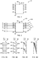
- Figure 1 illustrates an example of an apparatus 10 comprising interconnection circuitry 40.
- the interconnection circuitry 40 comprises a plurality N of radio ports 20 for interconnection with radio circuits 2 and a plurality of M antenna ports 30 for interconnection with antennas 4.
- the interconnection circuitry 40 is configured to enable interconnection of each of a set of radio ports 20 to different non-overlapping sets of antenna ports 30.
- the interconnected set of radio ports 20 are controllable and the set of antenna ports 30 are controllable.
- the interconnection circuitry 40 comprises at least one control port 42 configured to receive a control signal 44 for determining the sets.
- Figure 2 illustrates the apparatus 10 of figure 1 when it is interconnected to multiple radio circuits 2 and to multiple antennas 4.
- Each of the N radio ports 20 is interconnected to a different radio circuit 2.
- Each of the antenna ports 30 is interconnected to a different antenna 4.
- m is a whole number greater than one.
- a whole number is a non-negative integer, for example, 0, 1, 2, 3...
- M N.
- Each of the figures 3A to 3D illustrate a different configuration of the interconnection circuitry 40.
- the interconnection circuitry 40 is configured to enable interconnection of each of one or more radio ports 20 to S different non-overlapping sets 50 of P antenna ports.
- P is controllable by a control signal 44.
- P 2 p (which may also be expressed as 2 ⁇ p), where p is a whole number.
- FIG 3A there is a one to one mapping between the eight radio ports 20 and the eight antenna ports 30.
- control signal 44 controls the value of P and the value of S and therefore controls the number S of operational radio ports 20 (number of operational communication channels).
- the control signal 44 may be adaptively controlled to determine the best suitable values of P and S given different circumstances in which the radio communication is operated.
- the interconnection circuitry 40 may be configured to enable compensated interconnection of each of the one or more radio ports 20 to different non-overlapping sets of P antenna ports 30 to enable controlled combination of the signals travelling via a shared radio port 20.
- the interconnections between that shared radio port 20 and the antenna ports 30 to which it is connected may experience differential phase compensation.
- the interconnection circuitry 40 may be comprised of one or more selection circuits 60.
- Figure 4A illustrates a module 70 comprising selection circuits 60.
- the module 70 may be used as interconnection circuitry 40 or multiple modules may be used to form interconnection circuitry 40, for example as further described in relation to figures 6A, 6B and 6C below.
- the module 70 comprises a cascade arrangement 80 of selection circuits 60.
- Each selection circuit 60 comprises two first ports 61 and two second ports 62.
- Each selection circuit 60 is configured to have a first configuration 71, as illustrated in figure 4B , defined by one to one mappings between each of the two first ports 61 and each of the two second ports 62.
- Each of the selection circuits 60 is also configured to have a second configuration 72, for example as illustrated in figure 4C , defined by a one to two mapping between a first one of the two first ports 61 and the two second ports 62.
- the second of the first two ports 61 is not connected to a second port 62.
- the cascade arrangement 80 comprises a first tier comprising a single selection circuit 60 that has its two second ports 62 interconnected to a first one of the first ports 61 of a first selection circuit 60 in a second, lower order tier and to a first one of the first ports 61 of a second selection circuit 60 in the second, lower order tier.
- the first ports A, B, C, D of the cascade arrangement 80 are interconnected to the first ports 61 of the selection circuit 60 in the first tier (A, C), to a second of the first ports 61 of a first one of the selection circuits 60 in the second tier (B) and to a second one of the first ports 61 of the second selection circuit 60 in the second tier (D).
- the second ports of the cascade arrangement A', B', C', D' are provided by the second ports 62 of the first selection circuit 60 in the second tier (A', B') and by the second ports 62 of the second selection circuit 60 in the second tier (C', D').
- the selection circuitry 60 in different tiers may be switched independently between configurations, however, the selection circuitry 60 within a common tier has the same configuration when switched.
- the different configurations of the cascade arrangement 80 illustrated in figure 4A are illustrated in figure 5A, 5B and 5C as mappings between the first ports A, B, C, D and the second ports A', B', C', D'.
- the cascade arrangement 80 of the module 70 has the selection circuitry 60 of the first tier in a first configuration and the selection circuits 60 of the second tier in a first configuration.
- first port A is mapped to second port A'
- first port B is mapped to second port B'
- first port C is mapped to second port C'
- first port D is mapped to second port D'.
- the mapping of the first/second ports is therefore 4x4.
- the cascade arrangement 80 of the module 70 has the selection circuitry 60 of the first tier in a first configuration and the selection circuits 60 of the second tier in a second configuration. This results in a one to two mapping between the first port A and the second ports A', B' and between the first port C and the second ports C', D'.
- the cascade arrangement 80 of the module 70 has the selection circuitry 60 of the first tier in a second configuration and the selection circuits 60 of the second tier in a second configuration. This results in a one to four mapping between the first port A and the second ports A', B', C', D'.
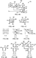
- the selection circuitry 60 may be configured to provide differential filtering between the path for the mapping between the first one of the first ports 61 and a first one of the second ports 62 when compared with the path for the mapping between the first one of the first ports 61 and the second of the second ports 62. This is illustrated in figure 4C by the presence of a filter 66 in one of the paths but not the other. However, it should be appreciated that both paths may have filters.
- the purpose of the filter or filters 66 is to compensate the signals provided via the different paths. This may for example be used such that a set of the second ports of the module 70 operate as a single virtual second port in that the signals are compensated so that they correlate at the first port of the module 70 (for reception) or the second ports of the module (for transmission).
- the first port A of the module 70 is mapped to the second ports A', B' of the module 70.
- the filters 66 provides phase compensation in the path AB'.
- the path AB' is therefore compensated compared to the path AA' to enable controlled combination of signals travelling via the respective paths.
- the first port A of the module 70 is mapped to the second ports A', B', C' and D' of the module 70.
- the filters 66 provide different phase compensation in the paths AA', AB', AC' and AD'.
- first/second mapping may be represented as 2x4 at a physical level.
- Phase compensation means that in operation there are in effect two first ports A, C and two virtual second ports.
- the virtual second port provided by the second ports A', B' maps to the first port A and the virtual port provided by the second port provided by the second ports C', D' maps to the first port C.
- the first/second mapping may be represented as 2x2 at a virtual level.
- mapping of the first/second ports is therefore 1x4 (physically) or if phase compensation is used such that all second ports operate as a virtual port, the mapping is 1x1 (virtually).
- the apparatus 10 comprising a module 70 may be configured to provide different phase compensation between different pairs of radio ports 20 and antenna ports 30 to enable phase compensation in respect of multiple antenna ports 30 interconnected to a shared radio port 20.
- the phase compensation provided by the filter 66 which may be a phase delay element, may be programmable via an input control signal. In this way the phase compensation between different pairs of radio ports and antenna ports may be programmable.
- the phase compensation can also be adaptively determined and programmed based on feedback from other parts of the circuitry.
- FIGS 6A, 6B and 6C illustrate different arrangements of interconnections circuitry 40 formed from one or more modules 70.
- the interconnection circuitry 70 in figure 6A comprises a single module 70 and the first ports A-D of the module 70 correspond to the radio ports 20 of the interconnection circuitry 40 and the second ports A'-D' of the module 70 correspond to the antenna ports 30 of the interconnection circuitry 40.
- the interconnection circuitry 40 is operable with 2 a radio ports 20, where a is selectable to be one of 0, 1, 2 and with 2 2 antenna ports 30. Where phase compensation occurs, the four antenna ports 30 operate as 2 a virtual antenna ports where there is a one to one mapping between the virtual antenna ports and the operational radio ports 20.
- the interconnection circuitry 70 in figure 6B comprises two modules 70 and the first ports A-D of the modules 70 correspond to the radio ports 20 of the interconnection circuitry and the second ports A'-D' of the modules 70 correspond to the antenna ports 30 of the interconnection circuitry 40.
- the interconnection circuitry 40 is operable with 2 a radio ports 20, where a is selectable to be one of 1, 2, 3 and with 2 3 antenna ports 30. Where phase compensation occurs, the 2 3 antenna ports 30 operate as 2 a virtual antenna ports where there is a one to one mapping between the 2 a virtual antenna ports and the 2 a operational radio ports 20.
- the interconnection circuitry 70 in figure 6C is similar to that of figure 6B but additionally comprises selection circuitry 60 that has respective second ports 62 connected to the first ports A' of the respective modules 70.
- the first ports of the selection circuit 60 and the remaining first ports of the modules 70 provide the radio ports of the interconnection circuitry 40.
- the second ports of the modules 70 provide the antenna ports 30 of the interconnection circuitry 40.
- the interconnection circuitry 40 is operable with 2 a radio ports 20, where a is selectable to be one of 0, 1, 2, 3 and with 2 3 antenna ports 30. Where phase compensation occurs, the 2 3 antenna ports 30 operate as 2 a virtual antenna ports where there is a one to one mapping between the 2 a virtual antenna ports and the 2 a operational radio ports 20.
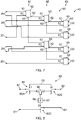
- Figure 7 illustrates the arrangement of selection circuits 60 for interconnection circuitry 40 configured, for example, in a manner similar to figure 6C .
- the interconnection circuitry 40 comprises a cascade arrangement 80 of selection circuits 60.
- Each selection circuit 60 comprises two first ports 61 and two second ports 62 as previously described. Also as previously described each selection circuit 60 is configured to have a first configuration 71 ( figure 4B ) defined by one to one mappings between each of the first ports 61 and each of the two second ports 62 and is configured to have a second configuration 72 ( figure 4C ) defined by a one to two mapping between a first one of the two first ports 61 and the two second ports 62. The second of the first two ports 61 is connected to a radio port 20.
- the cascade arrangement 80 comprises a radio tier 81 having a selection circuit 60.
- Each of the two first ports 61 of that selection circuit 60 are connected to a different radio port 20 and each of the two second ports 62 is connected to a first port of different selection circuit 60 in an adjacent lower order tier 85 of selection circuits 60.
- the cascade arrangement 80 also comprises an antenna tier 83 of multiple selection circuits 60 having only one of the two first ports 61 connected to a radio port 20, the other first one of the first ports 61 being connected to a second port 62 of a selection circuit 60 in an adjacent higher order tier 85 and having each of the two second ports 62 connected to different antenna ports 30.
- the cascade arrangement 80 also comprises an intermediate tier 85 of multiple selection circuits 60 having only one of the two first ports 61 connected to a radio port 20, the other of the two first ports 61 being connected to a second port 62 of a selection circuit 60 in an adjacent higher order tier 81 and having each of the two second ports 62 connected to a first one of the first ports 61 of different selection circuits 60 in an adjacent lower order tier 83.
- FIG. 8 illustrates an example of selection circuit 60.
- the selection circuit 60 comprises a bypass 84 configured in the first configuration to bypass a junction 86 and interconnect each of the two first ports 61 to the respective ones of the two second ports 62 and configured, in a second configuration, to couple a first one of the two first ports 61 to respective ones of the two second ports 62 via the junction 86.
- the first one of the first ports 61 is coupled to one of the second ports 62 via a phase element 66 configured to control a differential phase introduced between the two second ports 62 by control signal 67.
- the junction 86 may be a splitter/combiner as illustrated, a combiner, a splitter, or an active switch for example.
- the control signal 67 may be an analog signal or a digital signal, or a mixture of both analog & digital and corresponding analog and/or digital circuitry and software may be used to provide the control signal 67.
- a first switch 82A interconnects the first one of the first ports 61 to a first one of the second ports 62 via a second switch 82B.
- a third switch 82C interconnects a second one of the first ports 61 to a second one of the second ports 62.
- the first switch 82A interconnects the first one of the first ports 61 to a splitter/combiner 86
- the second switch 82B interconnects the first one of the second ports 62 to the splitter/combiner 86
- the third switch 82C interconnects the second one of the second ports 62 to the splitter/combiner via the phase element 66.
- phase element 66 may have a fixed phase. In other embodiments, the phase element 66 may be programmable such that its phase may be varied via control signal 67
- a filter 66 may comprise passive/tunable/adaptive impedance matching elements.
- Figure 9 illustrates an example of a communication apparatus 100 comprising apparatus 10.
- the apparatus 100 is schematically illustrated in figure 2 and comprises multiple radio circuits 2, the apparatus 10 comprising interconnection circuitry 40 and multiple antennas 4.
- the multiple antennas 4 are configured for diversity.
- Each of the antennas 4 has diversity with respect to the other antennas.
- the diversity may, for example, arise from orientation.
- some of the antennas 4 are oriented in the +x direction, other antennas are oriented in the -x direction, other antennas are oriented in the +y direction and other antennas are oriented in the -y direction.
- the x and y directions are orthogonal and the +/- directions are parallel but in opposite sense ( ⁇ phase difference).
- some of the antennas 4 are physically separated in the x direction and other antennas are physically separated in the y direction.
- the interconnection circuitry 40 of the apparatus 10 may be configured to operate a plurality (Y) of antennas 4 interconnected with a shared radio port 20 as a single virtual antenna, for each of multiple (X) radio ports 20 to provide multiple input multiple output for X inputs and Y outputs, where Y and X are controllable via the interconnection circuitry 40.
- the apparatus 100 may operate as a multiple antenna system, which may be used in a number of different applications.
- a multiple antenna system may, for example, be configured to operate the multiple antennas simultaneously.
- a multiple antenna system may, for example, have multiple different antennas configured to operate at different frequencies or so that the system can operate in different frequency channels.
- a multiple antenna system may, for example, have multiple different antennas configured to operate in orthogonal channels created by orthogonal signal encoding.
- a multiple antenna system may, for example, have multiple different antennas configured to operate simultaneously in the same channel.
- Diversity may be introduced between the multiple antennas by, for example, arranging the antennas so that they have diversity arising from different orientations and/or spatial separation. Diversity may be modified and compensated for using the interconnection circuitry 40.
- the application of these various techniques may, for example, be used to create multiple input (MI), multiple output (MO) and multiple input multiple output (MIMO) systems.
- a MO system may, for example may be used for beam-forming, spatial multiplexing or diversity transmission.
- a MI system may, for example be used for determining a bearing (reverse beam-forming), spatial multiplexing reception or diversity reception.
- circuitry refers to all of the following:
- circuitry would also cover an implementation of merely a processor (or multiple processors) or portion of a processor and its (or their) accompanying software and/or firmware.
- circuitry would also cover, for example and if applicable to the particular claim element, a baseband integrated circuit or applications processor integrated circuit for a mobile phone or a similar integrated circuit in a server, a cellular network device, or other network device.
- the radio port means may comprise any means that enables signal communication with the interconnection means.
- the radio port means may, for example, comprise one or more of transmission lines, connectors, couplers, circuit board contact pads, metal pins, spring loaded metal contacts, pogo pins, as a non-exhaustive list.
- the antenna means may be any suitable means for transferring electromagnetic energy between the air interface and the interconnection means.
- the radio circuits 2 and the antennas 4 may be configured to operate in one or more of a plurality of operational resonant frequency bands.
- the operational resonant frequency bands may include (but are not limited to) Long Term Evolution (LTE) (US) (734 to 746 MHz and 869 to 894 MHz), Long Term Evolution (LTE) (rest of the world) (791 to 821 MHz and 925 to 960 MHz), amplitude modulation (AM) radio (0.535-1.705 MHz); frequency modulation (FM) radio (76-108 MHz); Bluetooth (2400-2483.5 MHz); wireless local area network (WLAN) (2400-2483.5 MHz); hiper local area network (HiperLAN) (5150-5850 MHz); global positioning system (GPS) (1570.42-1580.42 MHz); US - Global system for mobile communications (US-GSM) 850 (824-894 MHz) and 1900 (1850 - 1990 MHz); European global system for mobile communications (EGSM) 900 (880-960 MHz) and
- a frequency band over which an antenna can efficiently operate is a frequency range where the antenna's return loss is less than an operational threshold. For example, efficient operation may occur when the antenna's return loss is better than (that is, less than) -4dB or -6dB.
- An operational resonant mode is a frequency range over which an antenna can efficiently operate.
- An operational resonant mode may be defined as where the return loss S11 of the antenna is greater than an operational threshold T such as, for example, 3 or 4 dB and where the radiated efficiency is greater than an operational threshold such as for example -3dB in an efficiency plot.
- Radiation efficiency does not include power lost due to poor VSWR (mismatch losses in the matching network which is not part of the antenna as such, but an additional circuit).
- the “total radiation efficiency” comprises the “radiation efficiency” and power lost due to poor VSWR [in dB].
- the efficiency operational threshold could alternatively be expressed in relation to “total radiation efficiency” rather than “radiation efficiency”.
Landscapes
- Engineering & Computer Science (AREA)
- Computer Networks & Wireless Communication (AREA)
- Signal Processing (AREA)
- Variable-Direction Aerials And Aerial Arrays (AREA)
Claims (15)
- Vorrichtung (10), umfassend:eine Vielzahl von Funkanschlüssen (20) zur Verbindung mit Funkschaltungen (2),eine Vielzahl von Antennenanschlüssen (30) zur Verbindung mit Antennen (4),Verbindungsschaltkreis(e) (40), der/die konfiguriert ist/sind, um Verbindung von jedem des einen oder der mehreren Funkanschlüsse (20) mit unterschiedlichen nicht-überlappenden Sätzen von P Antennenanschlüssen (30) zu ermöglichen, wobei P steuerbar ist und P = 2^p, wobei p eine ganze Zahl ist, und wobei der/die Verbindungsschaltkreis(e) konfiguriert ist/sind, um eine eins-zu-P-Abbildung zwischen den Funkanschlüssen (20) und den Antennenanschlüssen (30) zu ermöglichen, wobei jeder Antennenanschluss (30) mit einem und nur einem Funkanschluss (20) verbunden ist; undmindestens einen Steueranschluss, der konfiguriert ist, um ein Steuersignal zum Ermitteln von P zu empfangen.
- Vorrichtung (10) nach Anspruch 1, wobei der/die Verbindungsschaltkreis(e) (40) konfiguriert ist/sind, um unterschiedliche Phasenkompensation zwischen unterschiedlichen Paaren von Funkanschlüssen (20) und Antennenanschlüssen (30) bereitzustellen, um Phasenkompensation in Bezug auf mehrere Antennenanschlüsse (30) bereitzustellen, die mit einem gemeinsam genutzten Funkanschluss verbunden sind.
- Vorrichtung (10) nach einem der vorhergehenden Ansprüche, wobei der/die Verbindungsschaltkreis(e) (40) konfiguriert ist/sind, um programmierbare Phasenkompensationen zwischen unterschiedlichen Paaren von Funkanschlüssen (20) und Antennenanschlüssen (30) bereitzustellen.
- Vorrichtung (10) nach einem der vorhergehenden Ansprüche, wobei der/die Verbindungsschaltkreis(e) (40) einen oder mehrere Auswahlschaltungen umfassen, wobei jede Auswahlschaltung erste Anschlüsse und zweite Anschlüsse umfasst und konfiguriert ist, um eine erste Konfiguration anzunehmen, die durch eins-zu-eins-Abbildungen zwischen den ersten Anschlüssen und den zweiten Anschlüssen definiert ist, und konfiguriert ist, um eine zweite Konfiguration anzunehmen, die durch 1-zu-2^q-Abbildungen zwischen den ersten Anschlüssen und den zweiten Anschlüssen definiert ist, wobei q eine nicht negative ganze Zahl ist, wobei der mindestens eine Steueranschluss konfiguriert ist, um ein Steuersignal zu empfangen, um Konfigurationen des einen oder der mehreren Auswahlschaltungen zu steuern.
- Vorrichtung (10) nach einem der vorhergehenden Ansprüche, wobei der/die Verbindungsschaltkreis(e) (40) eine Kaskadenanordnung von Auswahlschaltungen umfasst, wobei jede Auswahlschaltung zwei erste Anschlüsse und zwei zweite Anschlüsse umfasst und konfiguriert ist, um eine erste Konfiguration aufzuweisen, die durch eins-zu-eins-Abbildungen zwischen jedem der beiden ersten Anschlüsse und jedem der beiden zweiten Anschlüsse definiert ist, und konfiguriert ist, um eine zweite Konfiguration aufzuweisen, die durch eine 1-zu-2-Abbildung zwischen einem der beiden ersten Anschlüsse und den beiden zweiten Anschlüsse konfiguriert ist.
- Vorrichtung (10) nach Anspruch 5, wobei die Kaskadenanordnung umfasst: eine Funkebene aus einer oder mehreren Auswahlschaltungen, wobei jeder der beiden ersten Anschlüsse mit einem anderen Funkanschluss verbunden ist und jeder der beiden zweiten Anschlüsse mit einem ersten Anschluss von anderen Auswahlschaltungen in einer benachbarten rangniederen Ebene der Auswahlschaltungen verbunden ist; und
eine Antennenebene aus mehreren Auswahlschaltungen, wobei nur einer der beiden ersten Anschlüsse mit einem Funkanschluss verbunden ist, wobei der andere der beiden ersten Anschlüsse mit einem zweiten Anschluss einer Auswahlschaltung in einer benachbarten höherrangigen Ebene verbunden ist, und wobei jeder der beiden zweiten Anschlüsse mit anderen Antennenanschlüssen (30) verbunden ist. - Vorrichtung (10) nach Anspruch 6, wobei die Kaskadenanordnung mindestens eine Zwischenebene aus mehreren Auswahlschaltungen umfasst, wobei nur einer der beiden ersten Anschlüsse mit einem Funkanschluss verbunden ist, wobei der andere der beiden ersten Anschlüsse mit einem zweiten Anschluss einer Auswahlschaltung in einer benachbarten ranghöheren Ebene verbunden ist, und wobei jeder der beiden zweiten Anschlüsse mit einem ersten Anschluss mit anderen Auswahlschaltungen in einer benachbarten rangniederen Ebene verbunden ist.
- Vorrichtung (10) nach einem der Ansprüche 4 bis 7, wobei jede Auswahlschaltung eine Umgehung umfasst, die in der ersten Konfiguration konfiguriert ist, um ein Splitter- und/oder Kombiniererelement zu umgehen und jeden der beiden ersten Anschlüsse an jeweils einen der beiden zweiten Anschlüsse zu koppeln, und in der zweiten Konfiguration konfiguriert ist, um einen der beiden ersten Anschlüsse über das Splitter- und/oder Kombiniererelement an jeweils einen der beiden zweiten Anschlüsse zu koppeln.
- Vorrichtung (10) nach einem der Ansprüche 4 bis 8, wobei jede Auswahlschaltung ein Phasenelement umfasst, das konfiguriert ist, um eine zwischen den beiden zweiten Anschlüssen eingeführte Phase zu steuern.
- Vorrichtung (10) nach Anspruch 9, wobei das Phasenelement eine programmierbare Phase aufweist.
- Vorrichtung (10) nach einem der vorhergehenden Ansprüche, ferner umfassend eine Vielzahl von Antennen (4), von denen jede mit einem Antennenanschluss verbunden ist, wobei die Vielzahl der Antennen (4) für Diversität konfiguriert ist.
- Vorrichtung (10) nach Anspruch 11, wobei mindestens einige der Antennen (4) in orthogonalen Richtungen ausgerichtet sind und mindestens einige der Antennen (4) räumlich getrennt sind.
- Vorrichtung (10) nach einem der vorhergehenden Ansprüche, wobei der/die Verbindungsschaltkreis(e) (40) konfiguriert ist/sind, um eine Vielzahl (Y) von Antennen (4), die über den/die Verbindungsschaltkreis(e) (40) mit einem gemeinsam genutzten Funkanschluss als einzige virtuelle Antenne verbunden ist/sind, für jeden von einer Vielzahl (X) von Funkanschlüsse (20) zu betreiben, um Mehrfacheingabe-Mehrfachausgabe bereitzustellen, wobei X steuerbar ist.
- Kommunikationsvorrichtung 100, umfassend eine Vorrichtung gemäß mindestens einem der Ansprüche 1 bis 13, eine Vielzahl von Funkschaltungen (2) und eine Vielzahl von Antennen (4).
- Verfahren, umfassend:Empfangen eines Steuersignals; undVerbinden von jedem des einen oder der mehreren betriebsfähigen Funkanschlüsse (20), des einen oder der mehreren Funkanschlüsse (20) zum Verbinden mit Funkschaltungen (2), mit unterschiedlichen nicht-überlappenden Sätzen von P Antennenanschlüsse (30), wobei die Antennenanschlüsse (30) zum Verbinden mit Antennen in Abhängigkeit von dem Steuersignal dienen, wobei P steuerbar ist und P = 2^p, wobei p eine ganze Zahl ist, wobei Verbinden umfasst, dass ein (einzelner) Funkanschluss (20) mit P Antennenanschlüsse (30) verbunden wird, wobei jeder Antennenanschluss (30) mit einem und nur einem Funkanschluss (20) verbunden ist.
Priority Applications (4)
| Application Number | Priority Date | Filing Date | Title |
|---|---|---|---|
| EP14198386.6A EP3035547B1 (de) | 2014-12-16 | 2014-12-16 | Vorrichtung und Verfahren für Mehrfachantennensysteme |
| ES14198386T ES2768177T3 (es) | 2014-12-16 | 2014-12-16 | Aparato y método para múltiples sistemas de antena |
| EP19187780.2A EP3576305B1 (de) | 2014-12-16 | 2014-12-16 | Vorrichtung mit kaskadierten antennenverbindungen |
| US14/969,655 US9680555B2 (en) | 2014-12-16 | 2015-12-15 | Apparatus and method for multiple antenna systems |
Applications Claiming Priority (1)
| Application Number | Priority Date | Filing Date | Title |
|---|---|---|---|
| EP14198386.6A EP3035547B1 (de) | 2014-12-16 | 2014-12-16 | Vorrichtung und Verfahren für Mehrfachantennensysteme |
Related Child Applications (2)
| Application Number | Title | Priority Date | Filing Date |
|---|---|---|---|
| EP19187780.2A Division-Into EP3576305B1 (de) | 2014-12-16 | 2014-12-16 | Vorrichtung mit kaskadierten antennenverbindungen |
| EP19187780.2A Division EP3576305B1 (de) | 2014-12-16 | 2014-12-16 | Vorrichtung mit kaskadierten antennenverbindungen |
Publications (2)
| Publication Number | Publication Date |
|---|---|
| EP3035547A1 EP3035547A1 (de) | 2016-06-22 |
| EP3035547B1 true EP3035547B1 (de) | 2019-11-20 |
Family
ID=52144425
Family Applications (2)
| Application Number | Title | Priority Date | Filing Date |
|---|---|---|---|
| EP14198386.6A Active EP3035547B1 (de) | 2014-12-16 | 2014-12-16 | Vorrichtung und Verfahren für Mehrfachantennensysteme |
| EP19187780.2A Active EP3576305B1 (de) | 2014-12-16 | 2014-12-16 | Vorrichtung mit kaskadierten antennenverbindungen |
Family Applications After (1)
| Application Number | Title | Priority Date | Filing Date |
|---|---|---|---|
| EP19187780.2A Active EP3576305B1 (de) | 2014-12-16 | 2014-12-16 | Vorrichtung mit kaskadierten antennenverbindungen |
Country Status (3)
| Country | Link |
|---|---|
| US (1) | US9680555B2 (de) |
| EP (2) | EP3035547B1 (de) |
| ES (1) | ES2768177T3 (de) |
Families Citing this family (2)
| Publication number | Priority date | Publication date | Assignee | Title |
|---|---|---|---|---|
| CN107437648B (zh) * | 2016-05-28 | 2021-04-20 | 富泰华工业(深圳)有限公司 | 多馈入超高频rfid标签天线 |
| KR102570773B1 (ko) | 2017-01-05 | 2023-08-25 | 삼성전자 주식회사 | 복수의 무선 신호들을 컴바이닝하는 방법 및 장치 |
Family Cites Families (16)
| Publication number | Priority date | Publication date | Assignee | Title |
|---|---|---|---|---|
| US1670A (en) | 1840-07-01 | Cylinder-mill for grinding corn and other grain | ||
| US3192490A (en) * | 1962-08-23 | 1965-06-29 | Westinghouse Electric Corp | Hybrid network having interconnected center tapped autotransformer windings |
| US3713158A (en) * | 1971-04-26 | 1973-01-23 | Litton Systems Inc | Digital feed system for electronic antenna array |
| US4165497A (en) * | 1977-11-11 | 1979-08-21 | Aiken Industries Inc. | Wideband RF switching matrix |
| US4517572A (en) * | 1982-07-28 | 1985-05-14 | Amstar Corporation | System for reducing blocking in an antenna switching matrix |
| US6405018B1 (en) * | 1999-01-11 | 2002-06-11 | Metawave Communications Corporation | Indoor distributed microcell |
| US6633551B1 (en) * | 1999-09-29 | 2003-10-14 | Lockheed Martin Corporation | High-rel beacon signal sequencer |
| US7148845B2 (en) | 2002-08-21 | 2006-12-12 | Broadcom Corporation | Antenna array including virtual antenna elements |
| US20070041457A1 (en) | 2005-08-22 | 2007-02-22 | Tamer Kadous | Method and apparatus for providing antenna diversity in a wireless communication system |
| KR101464510B1 (ko) | 2007-10-17 | 2014-11-26 | 삼성전자주식회사 | Mimo 안테나 장치 |
| US8638872B2 (en) | 2009-03-27 | 2014-01-28 | The Regents Of The University Of California | Space-time-state block coded MIMO communication system using reconfigurable antennas |
| US20110235755A1 (en) | 2010-03-23 | 2011-09-29 | Airgain, Inc. | Mimo radio system with antenna signal combiner |
| CN104272642B (zh) * | 2012-03-19 | 2018-02-02 | 瑞典爱立信有限公司 | 用于接收下行链路控制信息的方法和用户设备 |
| US9240813B2 (en) * | 2012-12-05 | 2016-01-19 | Telefonaktiebolaget L M Ericsson (Publ) | Distributed digitally convertible radio (DDCR) |
| US9172441B2 (en) * | 2013-02-08 | 2015-10-27 | Rf Micro Devices, Inc. | Front end circuitry for carrier aggregation configurations |
| FR3021813B1 (fr) * | 2014-05-28 | 2017-12-08 | Tekcem | Communication radio utilisant une pluralite d'antennes selectionnees |
-
2014
- 2014-12-16 EP EP14198386.6A patent/EP3035547B1/de active Active
- 2014-12-16 EP EP19187780.2A patent/EP3576305B1/de active Active
- 2014-12-16 ES ES14198386T patent/ES2768177T3/es active Active
-
2015
- 2015-12-15 US US14/969,655 patent/US9680555B2/en active Active
Non-Patent Citations (1)
| Title |
|---|
| None * |
Also Published As
| Publication number | Publication date |
|---|---|
| EP3576305A1 (de) | 2019-12-04 |
| ES2768177T3 (es) | 2020-06-22 |
| EP3576305B1 (de) | 2021-06-30 |
| US9680555B2 (en) | 2017-06-13 |
| US20160173184A1 (en) | 2016-06-16 |
| EP3035547A1 (de) | 2016-06-22 |
Similar Documents
| Publication | Publication Date | Title |
|---|---|---|
| US9444609B2 (en) | RF front end arrangement and method for sharing first and second antennas by different frequency bands | |
| EP2332212B1 (de) | Antennenanordnung zur störungsverringerung und mimo-kommunikation | |
| US7245938B2 (en) | Wireless antenna traffic matrix | |
| US8390518B2 (en) | Adaptive adjustment of an antenna arrangement for exploiting polarization and/or beamforming separation | |
| CN110915148B (zh) | 一种用于波束成形的天线布置和方法 | |
| KR20080030473A (ko) | 강화된 다이버시티를 구비하는 ofdm 기반 mimo시스템을 위한 방법 및 시스템 | |
| WO2011124180A2 (zh) | 天线设备、基站系统和调整天线设备的方法 | |
| EP3497750B1 (de) | Antennenstapel | |
| CN109119765A (zh) | 含带增强半功率波束宽度控制的天线阵列的蜂窝通信系统 | |
| EP3793030B1 (de) | Antenne | |
| CN104823323A (zh) | 具有4tx/4rx三频带天线布置的无线通信节点 | |
| EP3035547B1 (de) | Vorrichtung und Verfahren für Mehrfachantennensysteme | |
| US20100003941A1 (en) | Antenna selector and communication device | |
| US9137749B2 (en) | Node in a wireless communication system, the node having different functional modes | |
| US11916307B2 (en) | Antenna | |
| EP3130038B1 (de) | Antennenanordnung | |
| CN112310662B (zh) | 具有带增强型半功率束宽控制的天线阵列的蜂窝通信系统 | |
| Gbafa et al. | Tx/Rx antenna system for full-duplex application | |
| KR20130104545A (ko) | 무선통신 시스템에서 안테나 구조 및 동작 방법 | |
| WO2009051558A1 (en) | Circuit-based multi port antenna | |
| US10044103B2 (en) | Wireless communication node with an antenna arrangement for triple band reception and transmission | |
| CN109273869B (zh) | 一种天线系统和移动终端 | |
| WO2025262065A1 (en) | Diversity combining circuits and cellular base stations including such diversity combining circuits | |
| CN119966458A (zh) | 天线切换系统及电子设备 | |
| WO2014120154A1 (en) | An apparatus for, at least, transmitting in a radio communications channel |
Legal Events
| Date | Code | Title | Description |
|---|---|---|---|
| PUAI | Public reference made under article 153(3) epc to a published international application that has entered the european phase |
Free format text: ORIGINAL CODE: 0009012 |
|
| AK | Designated contracting states |
Kind code of ref document: A1 Designated state(s): AL AT BE BG CH CY CZ DE DK EE ES FI FR GB GR HR HU IE IS IT LI LT LU LV MC MK MT NL NO PL PT RO RS SE SI SK SM TR |
|
| AX | Request for extension of the european patent |
Extension state: BA ME |
|
| STAA | Information on the status of an ep patent application or granted ep patent |
Free format text: STATUS: REQUEST FOR EXAMINATION WAS MADE |
|
| 17P | Request for examination filed |
Effective date: 20161214 |
|
| RBV | Designated contracting states (corrected) |
Designated state(s): AL AT BE BG CH CY CZ DE DK EE ES FI FR GB GR HR HU IE IS IT LI LT LU LV MC MK MT NL NO PL PT RO RS SE SI SK SM TR |
|
| STAA | Information on the status of an ep patent application or granted ep patent |
Free format text: STATUS: EXAMINATION IS IN PROGRESS |
|
| 17Q | First examination report despatched |
Effective date: 20180523 |
|
| GRAP | Despatch of communication of intention to grant a patent |
Free format text: ORIGINAL CODE: EPIDOSNIGR1 |
|
| STAA | Information on the status of an ep patent application or granted ep patent |
Free format text: STATUS: GRANT OF PATENT IS INTENDED |
|
| INTG | Intention to grant announced |
Effective date: 20190306 |
|
| GRAJ | Information related to disapproval of communication of intention to grant by the applicant or resumption of examination proceedings by the epo deleted |
Free format text: ORIGINAL CODE: EPIDOSDIGR1 |
|
| STAA | Information on the status of an ep patent application or granted ep patent |
Free format text: STATUS: EXAMINATION IS IN PROGRESS |
|
| INTC | Intention to grant announced (deleted) | ||
| GRAS | Grant fee paid |
Free format text: ORIGINAL CODE: EPIDOSNIGR3 |
|
| STAA | Information on the status of an ep patent application or granted ep patent |
Free format text: STATUS: GRANT OF PATENT IS INTENDED |
|
| RAP1 | Party data changed (applicant data changed or rights of an application transferred) |
Owner name: NOKIA TECHNOLOGIES OY |
|
| GRAP | Despatch of communication of intention to grant a patent |
Free format text: ORIGINAL CODE: EPIDOSNIGR1 |
|
| INTG | Intention to grant announced |
Effective date: 20190911 |
|
| GRAA | (expected) grant |
Free format text: ORIGINAL CODE: 0009210 |
|
| STAA | Information on the status of an ep patent application or granted ep patent |
Free format text: STATUS: THE PATENT HAS BEEN GRANTED |
|
| AK | Designated contracting states |
Kind code of ref document: B1 Designated state(s): AL AT BE BG CH CY CZ DE DK EE ES FI FR GB GR HR HU IE IS IT LI LT LU LV MC MK MT NL NO PL PT RO RS SE SI SK SM TR |
|
| REG | Reference to a national code |
Ref country code: GB Ref legal event code: FG4D |
|
| REG | Reference to a national code |
Ref country code: CH Ref legal event code: EP |
|
| REG | Reference to a national code |
Ref country code: IE Ref legal event code: FG4D |
|
| REG | Reference to a national code |
Ref country code: DE Ref legal event code: R096 Ref document number: 602014057026 Country of ref document: DE |
|
| REG | Reference to a national code |
Ref country code: AT Ref legal event code: REF Ref document number: 1205350 Country of ref document: AT Kind code of ref document: T Effective date: 20191215 |
|
| REG | Reference to a national code |
Ref country code: NL Ref legal event code: MP Effective date: 20191120 |
|
| REG | Reference to a national code |
Ref country code: LT Ref legal event code: MG4D |
|
| PG25 | Lapsed in a contracting state [announced via postgrant information from national office to epo] |
Ref country code: NL Free format text: LAPSE BECAUSE OF FAILURE TO SUBMIT A TRANSLATION OF THE DESCRIPTION OR TO PAY THE FEE WITHIN THE PRESCRIBED TIME-LIMIT Effective date: 20191120 Ref country code: LV Free format text: LAPSE BECAUSE OF FAILURE TO SUBMIT A TRANSLATION OF THE DESCRIPTION OR TO PAY THE FEE WITHIN THE PRESCRIBED TIME-LIMIT Effective date: 20191120 Ref country code: SE Free format text: LAPSE BECAUSE OF FAILURE TO SUBMIT A TRANSLATION OF THE DESCRIPTION OR TO PAY THE FEE WITHIN THE PRESCRIBED TIME-LIMIT Effective date: 20191120 Ref country code: LT Free format text: LAPSE BECAUSE OF FAILURE TO SUBMIT A TRANSLATION OF THE DESCRIPTION OR TO PAY THE FEE WITHIN THE PRESCRIBED TIME-LIMIT Effective date: 20191120 Ref country code: BG Free format text: LAPSE BECAUSE OF FAILURE TO SUBMIT A TRANSLATION OF THE DESCRIPTION OR TO PAY THE FEE WITHIN THE PRESCRIBED TIME-LIMIT Effective date: 20200220 Ref country code: FI Free format text: LAPSE BECAUSE OF FAILURE TO SUBMIT A TRANSLATION OF THE DESCRIPTION OR TO PAY THE FEE WITHIN THE PRESCRIBED TIME-LIMIT Effective date: 20191120 Ref country code: GR Free format text: LAPSE BECAUSE OF FAILURE TO SUBMIT A TRANSLATION OF THE DESCRIPTION OR TO PAY THE FEE WITHIN THE PRESCRIBED TIME-LIMIT Effective date: 20200221 Ref country code: NO Free format text: LAPSE BECAUSE OF FAILURE TO SUBMIT A TRANSLATION OF THE DESCRIPTION OR TO PAY THE FEE WITHIN THE PRESCRIBED TIME-LIMIT Effective date: 20200220 |
|
| PG25 | Lapsed in a contracting state [announced via postgrant information from national office to epo] |
Ref country code: HR Free format text: LAPSE BECAUSE OF FAILURE TO SUBMIT A TRANSLATION OF THE DESCRIPTION OR TO PAY THE FEE WITHIN THE PRESCRIBED TIME-LIMIT Effective date: 20191120 Ref country code: RS Free format text: LAPSE BECAUSE OF FAILURE TO SUBMIT A TRANSLATION OF THE DESCRIPTION OR TO PAY THE FEE WITHIN THE PRESCRIBED TIME-LIMIT Effective date: 20191120 Ref country code: IS Free format text: LAPSE BECAUSE OF FAILURE TO SUBMIT A TRANSLATION OF THE DESCRIPTION OR TO PAY THE FEE WITHIN THE PRESCRIBED TIME-LIMIT Effective date: 20200320 |
|
| REG | Reference to a national code |
Ref country code: ES Ref legal event code: FG2A Ref document number: 2768177 Country of ref document: ES Kind code of ref document: T3 Effective date: 20200622 |
|
| PG25 | Lapsed in a contracting state [announced via postgrant information from national office to epo] |
Ref country code: AL Free format text: LAPSE BECAUSE OF FAILURE TO SUBMIT A TRANSLATION OF THE DESCRIPTION OR TO PAY THE FEE WITHIN THE PRESCRIBED TIME-LIMIT Effective date: 20191120 |
|
| PG25 | Lapsed in a contracting state [announced via postgrant information from national office to epo] |
Ref country code: CZ Free format text: LAPSE BECAUSE OF FAILURE TO SUBMIT A TRANSLATION OF THE DESCRIPTION OR TO PAY THE FEE WITHIN THE PRESCRIBED TIME-LIMIT Effective date: 20191120 Ref country code: RO Free format text: LAPSE BECAUSE OF FAILURE TO SUBMIT A TRANSLATION OF THE DESCRIPTION OR TO PAY THE FEE WITHIN THE PRESCRIBED TIME-LIMIT Effective date: 20191120 Ref country code: EE Free format text: LAPSE BECAUSE OF FAILURE TO SUBMIT A TRANSLATION OF THE DESCRIPTION OR TO PAY THE FEE WITHIN THE PRESCRIBED TIME-LIMIT Effective date: 20191120 Ref country code: PT Free format text: LAPSE BECAUSE OF FAILURE TO SUBMIT A TRANSLATION OF THE DESCRIPTION OR TO PAY THE FEE WITHIN THE PRESCRIBED TIME-LIMIT Effective date: 20200412 Ref country code: DK Free format text: LAPSE BECAUSE OF FAILURE TO SUBMIT A TRANSLATION OF THE DESCRIPTION OR TO PAY THE FEE WITHIN THE PRESCRIBED TIME-LIMIT Effective date: 20191120 |
|
| REG | Reference to a national code |
Ref country code: CH Ref legal event code: PL |
|
| REG | Reference to a national code |
Ref country code: AT Ref legal event code: MK05 Ref document number: 1205350 Country of ref document: AT Kind code of ref document: T Effective date: 20191120 |
|
| REG | Reference to a national code |
Ref country code: DE Ref legal event code: R097 Ref document number: 602014057026 Country of ref document: DE |
|
| REG | Reference to a national code |
Ref country code: BE Ref legal event code: MM Effective date: 20191231 |
|
| PG25 | Lapsed in a contracting state [announced via postgrant information from national office to epo] |
Ref country code: SK Free format text: LAPSE BECAUSE OF FAILURE TO SUBMIT A TRANSLATION OF THE DESCRIPTION OR TO PAY THE FEE WITHIN THE PRESCRIBED TIME-LIMIT Effective date: 20191120 Ref country code: MC Free format text: LAPSE BECAUSE OF FAILURE TO SUBMIT A TRANSLATION OF THE DESCRIPTION OR TO PAY THE FEE WITHIN THE PRESCRIBED TIME-LIMIT Effective date: 20191120 Ref country code: SM Free format text: LAPSE BECAUSE OF FAILURE TO SUBMIT A TRANSLATION OF THE DESCRIPTION OR TO PAY THE FEE WITHIN THE PRESCRIBED TIME-LIMIT Effective date: 20191120 |
|
| PLBE | No opposition filed within time limit |
Free format text: ORIGINAL CODE: 0009261 |
|
| STAA | Information on the status of an ep patent application or granted ep patent |
Free format text: STATUS: NO OPPOSITION FILED WITHIN TIME LIMIT |
|
| 26N | No opposition filed |
Effective date: 20200821 |
|
| GBPC | Gb: european patent ceased through non-payment of renewal fee |
Effective date: 20200220 |
|
| PG25 | Lapsed in a contracting state [announced via postgrant information from national office to epo] |
Ref country code: IE Free format text: LAPSE BECAUSE OF NON-PAYMENT OF DUE FEES Effective date: 20191216 Ref country code: LU Free format text: LAPSE BECAUSE OF NON-PAYMENT OF DUE FEES Effective date: 20191216 |
|
| PG25 | Lapsed in a contracting state [announced via postgrant information from national office to epo] |
Ref country code: LI Free format text: LAPSE BECAUSE OF NON-PAYMENT OF DUE FEES Effective date: 20191231 Ref country code: AT Free format text: LAPSE BECAUSE OF FAILURE TO SUBMIT A TRANSLATION OF THE DESCRIPTION OR TO PAY THE FEE WITHIN THE PRESCRIBED TIME-LIMIT Effective date: 20191120 Ref country code: SI Free format text: LAPSE BECAUSE OF FAILURE TO SUBMIT A TRANSLATION OF THE DESCRIPTION OR TO PAY THE FEE WITHIN THE PRESCRIBED TIME-LIMIT Effective date: 20191120 Ref country code: BE Free format text: LAPSE BECAUSE OF NON-PAYMENT OF DUE FEES Effective date: 20191231 Ref country code: CH Free format text: LAPSE BECAUSE OF NON-PAYMENT OF DUE FEES Effective date: 20191231 Ref country code: PL Free format text: LAPSE BECAUSE OF FAILURE TO SUBMIT A TRANSLATION OF THE DESCRIPTION OR TO PAY THE FEE WITHIN THE PRESCRIBED TIME-LIMIT Effective date: 20191120 |
|
| PG25 | Lapsed in a contracting state [announced via postgrant information from national office to epo] |
Ref country code: IT Free format text: LAPSE BECAUSE OF FAILURE TO SUBMIT A TRANSLATION OF THE DESCRIPTION OR TO PAY THE FEE WITHIN THE PRESCRIBED TIME-LIMIT Effective date: 20191120 Ref country code: GB Free format text: LAPSE BECAUSE OF NON-PAYMENT OF DUE FEES Effective date: 20200220 |
|
| PG25 | Lapsed in a contracting state [announced via postgrant information from national office to epo] |
Ref country code: CY Free format text: LAPSE BECAUSE OF FAILURE TO SUBMIT A TRANSLATION OF THE DESCRIPTION OR TO PAY THE FEE WITHIN THE PRESCRIBED TIME-LIMIT Effective date: 20191120 |
|
| PG25 | Lapsed in a contracting state [announced via postgrant information from national office to epo] |
Ref country code: MT Free format text: LAPSE BECAUSE OF FAILURE TO SUBMIT A TRANSLATION OF THE DESCRIPTION OR TO PAY THE FEE WITHIN THE PRESCRIBED TIME-LIMIT Effective date: 20191120 Ref country code: HU Free format text: LAPSE BECAUSE OF FAILURE TO SUBMIT A TRANSLATION OF THE DESCRIPTION OR TO PAY THE FEE WITHIN THE PRESCRIBED TIME-LIMIT; INVALID AB INITIO Effective date: 20141216 |
|
| PG25 | Lapsed in a contracting state [announced via postgrant information from national office to epo] |
Ref country code: TR Free format text: LAPSE BECAUSE OF FAILURE TO SUBMIT A TRANSLATION OF THE DESCRIPTION OR TO PAY THE FEE WITHIN THE PRESCRIBED TIME-LIMIT Effective date: 20191120 |
|
| PG25 | Lapsed in a contracting state [announced via postgrant information from national office to epo] |
Ref country code: MK Free format text: LAPSE BECAUSE OF FAILURE TO SUBMIT A TRANSLATION OF THE DESCRIPTION OR TO PAY THE FEE WITHIN THE PRESCRIBED TIME-LIMIT Effective date: 20191120 |
|
| PGFP | Annual fee paid to national office [announced via postgrant information from national office to epo] |
Ref country code: ES Payment date: 20250117 Year of fee payment: 11 |
|
| PGFP | Annual fee paid to national office [announced via postgrant information from national office to epo] |
Ref country code: DE Payment date: 20251104 Year of fee payment: 12 |
|
| PGFP | Annual fee paid to national office [announced via postgrant information from national office to epo] |
Ref country code: FR Payment date: 20251110 Year of fee payment: 12 |