EP3035518B1 - Electrosurgical generator controller for regulation of electrosurgical generator output power - Google Patents
Electrosurgical generator controller for regulation of electrosurgical generator output power Download PDFInfo
- Publication number
- EP3035518B1 EP3035518B1 EP16151586.1A EP16151586A EP3035518B1 EP 3035518 B1 EP3035518 B1 EP 3035518B1 EP 16151586 A EP16151586 A EP 16151586A EP 3035518 B1 EP3035518 B1 EP 3035518B1
- Authority
- EP
- European Patent Office
- Prior art keywords
- current
- signal
- mode
- voltage
- constant
- Prior art date
- Legal status (The legal status is an assumption and is not a legal conclusion. Google has not performed a legal analysis and makes no representation as to the accuracy of the status listed.)
- Active
Links
Images


Classifications
-
- A—HUMAN NECESSITIES
- A61—MEDICAL OR VETERINARY SCIENCE; HYGIENE
- A61B—DIAGNOSIS; SURGERY; IDENTIFICATION
- A61B18/00—Surgical instruments, devices or methods for transferring non-mechanical forms of energy to or from the body
- A61B18/04—Surgical instruments, devices or methods for transferring non-mechanical forms of energy to or from the body by heating
- A61B18/12—Surgical instruments, devices or methods for transferring non-mechanical forms of energy to or from the body by heating by passing a current through the tissue to be heated, e.g. high-frequency current
- A61B18/1206—Generators therefor
-
- H—ELECTRICITY
- H02—GENERATION; CONVERSION OR DISTRIBUTION OF ELECTRIC POWER
- H02M—APPARATUS FOR CONVERSION BETWEEN AC AND AC, BETWEEN AC AND DC, OR BETWEEN DC AND DC, AND FOR USE WITH MAINS OR SIMILAR POWER SUPPLY SYSTEMS; CONVERSION OF DC OR AC INPUT POWER INTO SURGE OUTPUT POWER; CONTROL OR REGULATION THEREOF
- H02M7/00—Conversion of ac power input into dc power output; Conversion of dc power input into ac power output
- H02M7/42—Conversion of dc power input into ac power output without possibility of reversal
- H02M7/44—Conversion of dc power input into ac power output without possibility of reversal by static converters
- H02M7/48—Conversion of dc power input into ac power output without possibility of reversal by static converters using discharge tubes with control electrode or semiconductor devices with control electrode
- H02M7/53—Conversion of dc power input into ac power output without possibility of reversal by static converters using discharge tubes with control electrode or semiconductor devices with control electrode using devices of a triode or transistor type requiring continuous application of a control signal
- H02M7/537—Conversion of dc power input into ac power output without possibility of reversal by static converters using discharge tubes with control electrode or semiconductor devices with control electrode using devices of a triode or transistor type requiring continuous application of a control signal using semiconductor devices only, e.g. single switched pulse inverters
- H02M7/5387—Conversion of dc power input into ac power output without possibility of reversal by static converters using discharge tubes with control electrode or semiconductor devices with control electrode using devices of a triode or transistor type requiring continuous application of a control signal using semiconductor devices only, e.g. single switched pulse inverters in a bridge configuration
- H02M7/53871—Conversion of dc power input into ac power output without possibility of reversal by static converters using discharge tubes with control electrode or semiconductor devices with control electrode using devices of a triode or transistor type requiring continuous application of a control signal using semiconductor devices only, e.g. single switched pulse inverters in a bridge configuration with automatic control of output voltage or current
-
- A—HUMAN NECESSITIES
- A61—MEDICAL OR VETERINARY SCIENCE; HYGIENE
- A61B—DIAGNOSIS; SURGERY; IDENTIFICATION
- A61B18/00—Surgical instruments, devices or methods for transferring non-mechanical forms of energy to or from the body
- A61B2018/00571—Surgical instruments, devices or methods for transferring non-mechanical forms of energy to or from the body for achieving a particular surgical effect
- A61B2018/00607—Coagulation and cutting with the same instrument
-
- A—HUMAN NECESSITIES
- A61—MEDICAL OR VETERINARY SCIENCE; HYGIENE
- A61B—DIAGNOSIS; SURGERY; IDENTIFICATION
- A61B18/00—Surgical instruments, devices or methods for transferring non-mechanical forms of energy to or from the body
- A61B2018/00636—Sensing and controlling the application of energy
- A61B2018/00642—Sensing and controlling the application of energy with feedback, i.e. closed loop control
- A61B2018/00648—Sensing and controlling the application of energy with feedback, i.e. closed loop control using more than one sensed parameter
-
- A—HUMAN NECESSITIES
- A61—MEDICAL OR VETERINARY SCIENCE; HYGIENE
- A61B—DIAGNOSIS; SURGERY; IDENTIFICATION
- A61B18/00—Surgical instruments, devices or methods for transferring non-mechanical forms of energy to or from the body
- A61B2018/00636—Sensing and controlling the application of energy
- A61B2018/00666—Sensing and controlling the application of energy using a threshold value
- A61B2018/00678—Sensing and controlling the application of energy using a threshold value upper
-
- A—HUMAN NECESSITIES
- A61—MEDICAL OR VETERINARY SCIENCE; HYGIENE
- A61B—DIAGNOSIS; SURGERY; IDENTIFICATION
- A61B18/00—Surgical instruments, devices or methods for transferring non-mechanical forms of energy to or from the body
- A61B2018/00636—Sensing and controlling the application of energy
- A61B2018/0069—Sensing and controlling the application of energy using fuzzy logic
-
- A—HUMAN NECESSITIES
- A61—MEDICAL OR VETERINARY SCIENCE; HYGIENE
- A61B—DIAGNOSIS; SURGERY; IDENTIFICATION
- A61B18/00—Surgical instruments, devices or methods for transferring non-mechanical forms of energy to or from the body
- A61B2018/00636—Sensing and controlling the application of energy
- A61B2018/00696—Controlled or regulated parameters
- A61B2018/0072—Current
-
- A—HUMAN NECESSITIES
- A61—MEDICAL OR VETERINARY SCIENCE; HYGIENE
- A61B—DIAGNOSIS; SURGERY; IDENTIFICATION
- A61B18/00—Surgical instruments, devices or methods for transferring non-mechanical forms of energy to or from the body
- A61B2018/00636—Sensing and controlling the application of energy
- A61B2018/00696—Controlled or regulated parameters
- A61B2018/00726—Duty cycle
-
- A—HUMAN NECESSITIES
- A61—MEDICAL OR VETERINARY SCIENCE; HYGIENE
- A61B—DIAGNOSIS; SURGERY; IDENTIFICATION
- A61B18/00—Surgical instruments, devices or methods for transferring non-mechanical forms of energy to or from the body
- A61B2018/00636—Sensing and controlling the application of energy
- A61B2018/00696—Controlled or regulated parameters
- A61B2018/00767—Voltage
-
- A—HUMAN NECESSITIES
- A61—MEDICAL OR VETERINARY SCIENCE; HYGIENE
- A61B—DIAGNOSIS; SURGERY; IDENTIFICATION
- A61B18/00—Surgical instruments, devices or methods for transferring non-mechanical forms of energy to or from the body
- A61B2018/00636—Sensing and controlling the application of energy
- A61B2018/00773—Sensed parameters
- A61B2018/00779—Power or energy
-
- A—HUMAN NECESSITIES
- A61—MEDICAL OR VETERINARY SCIENCE; HYGIENE
- A61B—DIAGNOSIS; SURGERY; IDENTIFICATION
- A61B18/00—Surgical instruments, devices or methods for transferring non-mechanical forms of energy to or from the body
- A61B2018/00636—Sensing and controlling the application of energy
- A61B2018/00773—Sensed parameters
- A61B2018/00827—Current
-
- A—HUMAN NECESSITIES
- A61—MEDICAL OR VETERINARY SCIENCE; HYGIENE
- A61B—DIAGNOSIS; SURGERY; IDENTIFICATION
- A61B18/00—Surgical instruments, devices or methods for transferring non-mechanical forms of energy to or from the body
- A61B2018/00636—Sensing and controlling the application of energy
- A61B2018/00773—Sensed parameters
- A61B2018/00875—Resistance or impedance
-
- A—HUMAN NECESSITIES
- A61—MEDICAL OR VETERINARY SCIENCE; HYGIENE
- A61B—DIAGNOSIS; SURGERY; IDENTIFICATION
- A61B18/00—Surgical instruments, devices or methods for transferring non-mechanical forms of energy to or from the body
- A61B2018/00636—Sensing and controlling the application of energy
- A61B2018/00773—Sensed parameters
- A61B2018/00892—Voltage
-
- A—HUMAN NECESSITIES
- A61—MEDICAL OR VETERINARY SCIENCE; HYGIENE
- A61B—DIAGNOSIS; SURGERY; IDENTIFICATION
- A61B18/00—Surgical instruments, devices or methods for transferring non-mechanical forms of energy to or from the body
- A61B18/04—Surgical instruments, devices or methods for transferring non-mechanical forms of energy to or from the body by heating
- A61B18/12—Surgical instruments, devices or methods for transferring non-mechanical forms of energy to or from the body by heating by passing a current through the tissue to be heated, e.g. high-frequency current
- A61B18/1206—Generators therefor
- A61B2018/1266—Generators therefor with DC current output
-
- A—HUMAN NECESSITIES
- A61—MEDICAL OR VETERINARY SCIENCE; HYGIENE
- A61B—DIAGNOSIS; SURGERY; IDENTIFICATION
- A61B18/00—Surgical instruments, devices or methods for transferring non-mechanical forms of energy to or from the body
- A61B18/04—Surgical instruments, devices or methods for transferring non-mechanical forms of energy to or from the body by heating
- A61B18/12—Surgical instruments, devices or methods for transferring non-mechanical forms of energy to or from the body by heating by passing a current through the tissue to be heated, e.g. high-frequency current
- A61B18/1206—Generators therefor
- A61B2018/1286—Generators therefor having a specific transformer
-
- H—ELECTRICITY
- H02—GENERATION; CONVERSION OR DISTRIBUTION OF ELECTRIC POWER
- H02M—APPARATUS FOR CONVERSION BETWEEN AC AND AC, BETWEEN AC AND DC, OR BETWEEN DC AND DC, AND FOR USE WITH MAINS OR SIMILAR POWER SUPPLY SYSTEMS; CONVERSION OF DC OR AC INPUT POWER INTO SURGE OUTPUT POWER; CONTROL OR REGULATION THEREOF
- H02M1/00—Details of apparatus for conversion
- H02M1/0067—Converter structures employing plural converter units, other than for parallel operation of the units on a single load
- H02M1/007—Plural converter units in cascade
Definitions
- An electrosurgical generator is commonly used in surgical practice to perform arc cutting and coagulation.
- the electrosurgical generator produces a high-frequency electric current to cut tissue with limited blood loss and enhanced cutting control compared to a metal blade.
- Standard industry practice is for electrosurgical generators to measure and average the alternating current (AC) output power over several cycles and use a low-bandwidth control loop to adjust the duty cycle of a pulse width modulated (PWM) converter, modulating the carrier of a fixed-output-impedance resonant inverter to achieve the desired output characteristic.
- PWM pulse width modulated
- One example of an industry practice is for electrosurgical generators to mimic medium-frequency (MF) amplitude modulated (AM) broadcast transmitters via a method commonly called the Kahn Envelope Elimination and Restoration technique.
- Such generators typically use a class-D or class-E RF output stage operating with constant voltage amplitude at the electrosurgical analogy of a carrier frequency.
- the generators are combined with an efficient converter power supply amplitude modulator, sometimes referred to as a class-S modulator.
- the converter power supply amplitude modulator may be configured to regulate the RF output voltage, current, or power dissipated in the tissue load to a desired power versus impedance characteristic called a power curve.
- a surgeon can induce joule heating in the affected cells; this causes the desired surgical effects of cutting, coagulation, and dissection.
- the electrosurgery utilizes joule heating produced by the electrosurgical generator.
- the electrosurgical generator produces an accurate power source output characteristic, to which maximum voltage and current limits are added. The voltage and current limits of the electrosurgical generator contribute to the safety of the process. Furthermore, in an exemplary embodiment the voltage and current limits are configured to produce particular tissue effects which may be desirable in various surgical applications.
- an electrosurgical generator control system produces constant power output without measuring output voltage or output current, and regulates the output power with substantially deadbeat control.
- the electrosurgical generator control system performs near deadbeat control by regulating inductor current to a specified value, equal to a reference current.
- the electrosurgical generator control system achieves a desired inverter output characteristic with an efficient and substantially deadbeat control method for AC output power.
- an exemplary electrosurgical generator control system switches between operating modes based in part on at least one of a measured output voltage, a measured inductor current, and by observing a duty cycle command generated by the control system.
- an exemplary control system provides the ability to adjust the voltage and current limits and facilitate precision control of desired tissue effects.
- the desired tissue effects may include at least one of cut depth and the amount of surface hemostatis versus thermal spread.
- an exemplary electrosurgical generator reduces unintended tissue damage by improving regulation of output power.
- an electrosurgical generator controls the power during a cycle, and reacts to a change in power if arcing occurs.
- Voltage sources especially, demonstrate the tendency to have large, uncontrolled power excursions during normal electrosurgical use. The magnitude of the power excursions may be dependent on various factors. One factor is how far the surgeon is away from the tissue when an arc occurs in the sinusoidal cycle.
- the current sources may introduce long, unintended arcs, even if distance from the tissue was well controlled.
- the electrosurgical generator may be configured to control power within a carrier frequency cycle for full arc and plasma control throughout the cycle. Power control within the duration of a carrier frequency cycle is advantageous over the prior art systems because arcing occurs faster than typical voltage or current detection feedback mechanisms can respond.
- the exemplary electrosurgical generator is less complex than prior art electrosurgical generators. Moreover, it is an objective of this application to present an inverter topology and control algorithm which combines current-mode and voltage-mode control to realize the desired output characteristic of an electrosurgical generator in a markedly simpler and more accurate fashion. By directing which of two conversion stages is to be current-mode controlled, constant power, constant current, and constant voltage outputs can be achieved with excellent regulation and fast transitions.
- an electrosurgical generator control scheme in an electrosurgical generator can provide near-deadbeat regulation of output power.
- the electrosurgical generator control scheme tends to assure that thermal spread is minimized by accurately supplying the specified power within a few cycles.
- fast and accurate regulation provided by the constant voltage mode minimizes unintentional tissue charring.
- an electrosurgical generator controller operates with near-deadbeat control to maintain a desired AC output of an electrosurgical generator, which operates in at least one of a constant voltage mode, a constant current mode, and a constant power mode.
- the mode selection is generally based on the impedance associated with the tissue being cut. Different types of tissue, such as muscle and fat, have different impedances.
- constant power output tends to uniformly vaporize tissue, resulting in clean dissection. Whereas constant voltage output tends to explosively vaporize or carbonize tissue (“black coagulation”), and constant current output tends to thermally coagulate tissue without vaporization ("white coagulation").
- Carbonization is surgically useful if the surgeon wishes to rapidly destroy surface tissue, and thermal coagulation is regularly coupled with mechanical pressure to seal hepatic or lymphatic vessels shut. However, it is desirable for the surgeon to operate using constant power output and importantly, return to using constant power output as quickly as possible if there is deviation.
- an electrosurgical generator 100 comprises a DC-DC buck converter 101, a DC-AC boost inverter 102, an inductor 103, a transformer 104, and an electrosurgical generator (ESG) control system 110.
- a DC voltage source Vg is electrically coupled to DC-DC buck converter 101.
- inductor 103 is electrically coupled between DC-DC buck converter 101 and DC-AC boost inverter 102.
- the output of DC-AC boost inverter 102 transmits power to the primary winding of transformer 104, which passes through the secondary winding of transformer 104 to the load Z.
- the load Z changes because tissue impedances vary, and also changes because the cutting process is an arc process. The impedance of an arc varies as it goes through several "phases" of formation and eventual extinguishment within a carrier frequency cycle.
- ESG control system 110 is in communication with both DC-DC buck converter 101 and DC-AC boost inverter 102.
- the ESG control system 110 is configured to control the duty cycle d 1 of DC-DC buck converter 101 and the duty cycle d 2 of DC-AC boost inverter 102.
- ESG control system 110 is configured to measure power characteristics of electrosurgical generator 100, and control electrosurgical generator 100 based at least in part on the measured power characteristics. Examples of the measured power characteristics include the current through inductor 103 and the voltage at the output of DC-AC boost inverter 102.
- ESG control system 110 controls buck converter 101 by generating duty cycles based on a combination and/or selection of duty cycle inputs from various controllers depending on the mode of operation (e.g., constant current, constant power, or constant voltage).
- mode of operation e.g., constant current, constant power, or constant voltage
- constant power is defined to mean the average power delivered in each switching cycle is regulated to a substantially fixed value.
- constant voltage and “constant current” are defined as the rms value of the AC voltage or current, respectively, being regulated to a substantially fixed value.
- the substantially fixed values of the constant power, constant voltage, and constant current may be selected by a user or selected from a lookup table.
- ESG control system 110 comprises a current-mode controller 111, a voltage-mode controller 112, a mode selector 113, and steering logic 114.
- Mode selector 113 compares the output voltage V out (t) and the inductor current i L (t) to "predetermined limits" (discussed in further detail herein) in order to determine the desired mode of operation of electrosurgical generator 100.
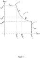
- An exemplary graphical representation of the desired output characteristics is illustrated in Figure 2 .
- the load impedance increases and causes the voltage to increase, the corresponding increasing output voltage triggers the transitioning of the operating mode from constant current (A) to constant power (B) to constant voltage (C).
- the corresponding decreasing output voltage triggers the opposite transitioning from constant voltage (C) to constant power (B) to constant current (A) operating modes.
- an ESG control system 310 comprises a current-mode controller 311, a voltage-mode controller 312, a mode selector 313, and steering logic 314.
- current-mode controller 311 compares the inductor current i L (t) to a control current limit i C .
- the control current limit i C is set by a user, or provided by a look-up table.
- current-mode controller 311 uses a latch circuit to generate a switching waveform ⁇ (t) with a duty cycle d 1 .
- the inputs of the latch circuit are the current comparison and a clock signal.
- the switching waveform ⁇ (t) is switched "high” at the start of a switching period if the inductor current i L (t) is lower than control current limit i C .
- the switching waveform ⁇ (t) is switched "low” in response to the inductor current i L (t) exceeding the control current limit i C .
- a comparison of the inductor current i L (t) to control current limit i C facilitates adjusting the inductor current i L (t) to match the control current limit i C .
- the current-mode controller regulates the inductor current i L (t) to an approximately constant value, substantially equal to control current limit i C .
- voltage-mode controller 312 comprises a comparator 321, a compensator 322, and a pulse-width modulator 323. Furthermore, in various embodiments, voltage-mode controller 312 compares the output voltage v out (t) with a reference voltage V max at comparator 321. The output of comparator 321 is communicated to compensator 322 which in turn outputs an error signal that drives PWM 323. In the various embodiments, the output of compensator 322 is an input signal to PWM 323, which sets the duty cycle d 2 of the signal.
- mode selector 313 comprises an encoder and performs multiple comparisons.
- the output voltage v out (t) is compared with a first voltage limit V limit_1 to generate "signal a”.
- the output voltage v out (t) is compared with a second voltage limit V limit_2 to generate "signal b”.
- the inductor current i L (t) is compared with a first current limit I limit_1 to generate a "signal c”.
- the inductor current i L (t) is compared with a second current limit I limit_2 to generate a "signal d".
- the mode selection is set by mode selector 313 based on the above described comparisons.
- Table 1 lists comparison outcomes and corresponding mode.
- Table 1 lists a "1" value if the output voltage or inductor current is greater than the compared limit, and a "0" value if the output voltage or inductor current is less than the compared limit.
- the encoder selects the constant voltage mode.
- the second voltage limit V limit_2 is equivalent to reference voltage V max , the same used in the comparison at voltage-mode controller 312.
- Table 1 a b c d Mode 0 0 1 1 I 1 0 1 0 P 1 1 0 0 V
- constant AC power output is achieved by setting duty cycle d 1 to a fixed value, and running the DC-AC boost inverter stage as a current-programmed boost inverter by varying duty cycle d 2 .
- electrosurgical generator controller 310 performs near deadbeat control by regulating inductor current to an approximately constant value, equal to a control current limit i C .
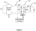
- Figure 4 represents an exemplary schematic of the electrosurgical generator in constant power output mode.
- the average voltage of v 1 (t) is constant in response to the input voltage Vg being constant, the DC-DC buck converter being bypassed by being set to 100% duty cycle, and no average voltage being able to exist across inductor L.
- the use of current programmed mode control results in the average current of i 1 (t) being regulated to an approximately fixed value with deadbeat or near-deadbeat control.
- duty cycle d 2 is varied by the current mode controller to maintain i 1 (t) at a fixed value.
- the power at input of DC-AC boost circuit 102 i.e., a switch network
- the switch network is nearly lossless, resulting in the output power being approximately equal to the input power. Since the input power is constant, the output power of DC-AC boost circuit 102 is also constant.
- constant voltage output is achieved by setting duty cycle d 1 of DC-DC buck converter 101 to a fixed value, and using voltage-mode control for duty cycle d 2 of DC-AC boost circuit 102.
- the voltage-mode control involves measuring the output voltage v out (t) of DC-AC boost circuit 102 with a sensor network, feeding the sensed output voltage v out (t) to a control loop in voltage-mode controller 312, and adjusting the converter's duty cycle command based on the relative difference between the measured output voltage v out (t) and the reference output voltage V max .
- the duty cycle d 2 is set to increase or decrease the output voltage to match V max .
- V max may be set by a user or based on values in a look-up table.
- constant current output is achieved by operating DC-AC boost circuit 102 at a fixed duty cycle d 2 and current-mode controlling DC-DC buck converter 101.
- the current-mode control accurately controls the average inductor current such that the output of buck converter 101 is a constant current.
- current-mode controller 111 compares inductor current i L (t) to control current limit i C , where the control current limit i C is a desired fixed value.
- electrosurgical generator controller 310 is configured to vary duty cycle d 1 in order to maintain inductor current i L (t) at the fixed value.
- i L (t) is measured with a sensor and not an estimated value.
- the constant current output mode produces an AC output current whose magnitude is regulated with near-deadbeat speed.
- an electrosurgical generator system implementing the three modes of constant power, constant voltage, or constant current produces a very fast, very accurate regulation of the AC output characteristic.
- Various modes are impacted by measured characteristics, while other modes do not need to respond to the same measured characteristics.
- electrosurgical generator controller 310 may switch between operating modes based in part on measured output voltage v out (t).
- electrosurgical generator controller 310 may adjust the operating parameters in the constant voltage mode based on the measured output voltage v out (t). In other words, the selection of which stage of the converter to current-mode control may be achieved with minimal feedback and without a need for extraneous measurements, averaging, or feedback of the output.
- Transitioning between the three modes is determined by monitoring the voltage of the primary winding of transformer 104 and the inductor current. As previously described, in accordance with one exemplary embodiment, the transition from one mode to the next is summarized in Table 1.
- An exemplary ESG transitions modes from constant current to constant power to constant voltage as the output voltage v out (t) increases. Specifically, in an exemplary embodiment, electrosurgical generator 300 operates in the constant current mode if the output voltage v out (t) is less than a first voltage limit V limit_1 . If the output voltage v out (t) exceeds the first voltage limit, electrosurgical generator 300 transitions to the constant power mode.
- electrosurgical generator 300 transitions to the constant voltage mode, where the output voltage v out (t) is limited and held constant.
- the first voltage limit V limit_1 and the second voltage limit V limit_2 are set by a user or from a look-up table.
- electrosurgical generator 300 transitions from constant voltage mode to constant power mode to constant current mode as inductor current i L (t) increases. Specifically, in an exemplary embodiment, electrosurgical generator 300 operates in the constant voltage mode if the inductor current i L (t) does not exceed a first current limit I limit_1 . If the inductor current i L (t) does exceed the first current limit I limit_1 , then the mode transitions to the constant power mode. If the inductor current i L (t) exceeds a second current limit I limit_2 , electrosurgical generator 300 transitions to the constant current mode, where the inductor current i L (t) is limited and held constant. In an exemplary embodiment, the first current limit I limit_1 and the second current limit I limit_2 are set by a user or from a look-up table.
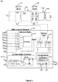
- an electrosurgical generator 500 having an ESG control system 510 comprises a current-mode controller 511, a voltage-mode controller 512, a mode selector 513, and steering logic 514.
- the operational mode of electrosurgical generator 500 is one of constant (or maximum) current I max , constant power P 1 from a buck converter, constant power P 2 from boost inverter, or constant (or maximum) voltage V max . These modes are illustrated in an exemplary embodiment with reference to Figure 6 .
- the output selection of mode selector 513 is communicated to steering logic 514.
- steering logic 514 controls which of at least one of current-mode controller 511 and voltage-mode controller 512 are enabled.
- steering logic 514 may select which conversion stage receives the output of current-mode controller 511 and/or voltage-mode controller 512. In various embodiments, steering logic 514 switches between operating either DC-DC buck converter 101 or DC-AC boost inverter 102 with current-mode control for constant power, depending on which portion of constant power regions (P 1 or P 2 ) is currently the operating mode. For example, the voltage mode controller 512 and/or current mode controller 511 may adjust the duty cycles d 1 and/or d 2 for the operating mode (constant current mode, constant voltage mode, constant power P 1 , or constant power P 2 ). Furthermore, steering logic 514 selects the duty cycle that each of DC-DC buck converter 101 and/or DC-AC boost inverter 102 receives.
- the current-mode controller 511 compares the inductor current i L (t) to a nonlinear carrier control current limit i C (t).
- the nonlinear carrier control current limit i C (t) is set by the selection of Pset, which may be done by a user, or provided by a look-up table.
- current-mode controller 511 uses a latch circuit to compare inductor current i L (t) to control current limit i C (t), comprising either a current limit signal (I) or a power limit signal (P 1 ).
- the control signal for a P/I switch is the mode signal, which is communicated from mode selector 513.
- the inputs of the latch circuit are a clock signal and the comparison of control current limit i C (t) and inductor current i L (t), comprising one of the current limit signal (I) or a power limit signal (P 1 ).
- the selection of the current-mode controller 511 output is in response to the current mode of the electrosurgical generator 500.
- the operating mode of the electrosurgical generator 500 may be communicated from the output of mode selector 513.
- the switching waveform ⁇ (t) is switched "high" at the start of a switching period if the inductor current i L (t) is lower than nonlinear carrier control current limit i C (t).
- the switching waveform ⁇ (t) is switched "low” in response to the inductor current i L (t) exceeding the nonlinear carrier control current limit i C (t).
- a comparison of the inductor current i L (t) to nonlinear carrier control current limit i C (t) facilitates adjusting pulse duration of buck converter's 101 duty cycle, as previously described.
- the average value of inductor current i L (t) is controlled to be substantially equal to fixed control current limit K*Pset, which is a fixed, non-time varying value.
- K*Pset a fixed, non-time varying value.
- the current-mode controller regulates the inductor current i L (t) to an approximately constant value, substantially equal to the fixed control current limit.
- a buck converter may also be configured to generate substantially constant power output.
- substantially constant power output of a buck converter may be achieved by adjusting a duty cycle's active period for the buck converter.
- a buck converter system comprises a power source Vg, a buck converter circuit 710, a controller 720, and a load 730.
- the impedance of the load may be static or dynamic.
- the controller 720 receives a feedback signal 711 representative of the output of the buck converter 710.
- the feedback signal 711 is a measurement of the current passing through an inductor 712 coupled to buck converter circuit 710.
- controller 720 receives real time feedback of the inductor current i L (t) from the buck converter.
- the feedback signal 711 is used by controller 720 to adjust the duration of the active and non-active portions of the duty cycle. Adjustment of the duty cycle portions in real time, or substantially in real time, may be configured to produce a constant power source from buck converter 710.
- two characteristics of the inductor feedback signal 711 are used to make the determination of duty cycle adjustments. The two characteristics are, first, the value of inductor current i L (t) and second, the slope of the change in the inductor current i L (t). These two characteristics may be used to provide implied information regarding the current and voltage of the output power into load 730, and this implied information may be used to adjust the magnitude of the duty cycle in real time and produce substantially constant power output.
- the pulse duration of the duty cycle of DC-DC buck converter 710 is varied using current mode controller 720.
- the varying pulse duration of the duty cycle controls the inductor current i L (t), which is responsive to load 730 in contact with buck converter 710.
- the impedance of load 730 varies, the voltage across inductor 712 also varies, and the current through inductor 712 varies as well.
- the active portion (also referred to as the pulse duration of the pulse period or the "on" portion) of the duty cycle is initiated.
- the active portion of the pulse period closes a switch between a power source and an inductor, thereby allowing power to flow through the inductor.
- the inductor feedback signal i L (t) is compared to a nonlinear carrier control current i C (t).
- the nonlinear carrier control current i C (t) is a time-varying, nonlinear control signal that may be set for customized uses based on the desired output power.
- the duty cycle switches to the non-active portion (also referred to as the "off' portion).
- the duty cycle stays in the non-active portion until the end of the pulse period. At the end of the pulse period, the cycle begins again with another pulse duration.
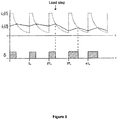
- the switching cycle has a fixed time period. Comparison of the inductor feedback signal i L (t) and the nonlinear carrier control current i C (t) is able to facilitate substantially constant power output based on a variable division of active and non-active portions of the duty cycle. As briefly described and with continued reference to Figure 8 , the inductor current value and the slope of the change in the inductor current i L (t) are used to adjust the duty cycle. By way of example and without limitation, the inductor current slope affects the timing of how long the inductor current i L (t) is less than the nonlinear carrier control current i C (t).
- a lower slope value indicates that the inductor current i L (t) is increasing at a slower rate, and therefore it will take a longer period of time until the inductor current i L (t) exceeds the control current i C (t). In other words, the more time is takes for the inductor current i L (t) to exceed the control current i C (t), the longer the corresponding pulse duration. For example, see the comparison between the pulse duration at 2T S and 3T S .
- a higher slope value of inductor current i L (t) indicates that the inductor current is increasing at a quicker rate, and therefore it will take a shorter period of time until the inductor current i L (t) exceeds the control current limit i C (t). The shorter period of time results in the duty cycle staying in the active portion for a shorter period and having shorter pulse duration.
- the nonlinear carrier control current i C (t) is part of a nonlinear carrier control (NLC) technique.
- NLC nonlinear carrier control
- the NLC technique applied to the buck converter is based on a nonlinear time dependent variable, which is the nonlinear carrier.
- the nonlinear time dependent variable is determined by the input voltage Vg, period of the switching cycle, and the desired power output.
- the application of NLC technique and production of substantially constant power output creates a buck converter that is a power source.
- the buck converter may implement NLC techniques to generate a fixed amount of power and be a power source.
- prior art use of NLC techniques was typically configured to cause a converter to absorb a fixed amount of power and be a power sink.
- a buck converter in combination with a boost inverter can produce a constant power source over a wider impedance range than using just a boost inverter alone.
- an electrosurgical generator as described herein is capable of operating over an impedance range of about 64 to 4000 ohms. Using both a boost inverter and buck converter to source constant power facilitates operating over the wide impedance range without unreasonably high peak voltages.
- producing constant power output in a buck converter with a load having variable resistance includes turning on a switch of the buck converter at the beginning of the duty cycle to initiate a pulse, and monitoring the current through the inductor.
- the inductor current linearly increases while the buck converter is operating in the active portion of the duty cycle.
- the exemplary method may further include comparing, at a control circuit, the inductor current i L (t) to a nonlinear carrier control current i C (t), and turning off the switch of the buck converter in response to the magnitude of the inductor current meeting or exceeding the magnitude of the nonlinear carrier control current.
- the inductor current ramps down during the non-active portion of the duty cycle.
- the changing inductor current slope corresponds to the changing impedance of the load, which may be used to adjust the pulse duration of the duty cycle in order to produce substantially constant power output from the buck converter.
- the inductor current has minor fluctuation during each cycle due to turning the buck converter on and off, and the minor fluctuation may not be due to any change in the load impedance.
- changes to the load impedance result in a change in inductor current slopes and a change to the average value of the inductor current.
- a buck converter with substantially constant power output is described in terms of implemention in an electrosurgical generator, such a buck converter may also be implemented in various applications, such as arc welding and gas-discharge lamps (i.e. street lamps).
- voltage-mode controller 512 comprises a comparator 521, a compensator 522, and a pulse-width modulator (PWM) 523. Furthermore, in an exemplary embodiment, voltage-mode controller 512 compares the measured output voltage v out (t) with a reference voltage V max at comparator 521. The output of comparator 521 is communicated to compensator 522 which in turn outputs an error signal that drives PWM 523. In the exemplary embodiment, the output of compensator 522 is an input signal to PWM 523, which sets the duty cycle d 2 of the signal in certain modes.
- constant voltage output may also be achieved by setting duty cycle d 1 of DC-DC buck converter 101 to a fixed value, and limiting the duty cycle d 2 of DC-AC boost inverter 102 to a maximum duty cycle d max .
- Implementing a duty cycle limit on DC-AC boost inverter 102 during the constant voltage output generally amounts to running DC-AC boost inverter 102 in an open-loop.
- limiting the duty cycle d 2 of DC-AC boost inverter 102 to a maximum duty cycle d max results in poorer steady-state output voltage regulation in comparison to mode transitions using direct measurement, but provides the significant advantage of limiting the peak output voltage on a per-cycle basis, with little or no risk of transient overshoot.
- the steady-state value of the maximum output voltage v out (t) is of lesser importance, as it would be unusual to operate in this output mode for any length of time.
- Per-cycle transient voltage limiting may be highly useful as a means to limit potential undesirable arcing.
- a maximum duty cycle may be easily varied without the need to linearize an output voltage measurement or tune a compensator, and in this exemplary embodiment no sensor is required on the output since no direct measurement is taken.
- mode selector 513 comprises an encoder and performs multiple comparisons.
- the output voltage v out (t) is compared with three separate voltage limits (V limit_1 , V limit_2 , V limit_3 ) to generate three voltage comparison signals.
- the inductor current i L (t) is compared with three separate current limits (I limit_1 , I limit_2 , I limit_3 ) to generate three current comparison signals.
- mode selector 513 uses the voltage comparison signals and the current comparison signals to determine whether electrosurgical generator 500 is operating in the constant current output region (A), the region P 1 of the constant power output region (B), the region P 2 of the constant power output region (B), or the constant voltage output region (C). Furthermore, the output mode signal from mode selector 513 controls the switch position in steering logic 514. Moreover, the output mode signal from mode selector 513 controls the switch position in current-mode controller 511. For example, if output voltage v out (t) exceeds the first voltage limit V limit_1 , the second voltage limit V limit_2 , and the third voltage limit V limit_3 , then the encoder selects the constant voltage mode.
- the constant voltage mode signal from mode selector 513 would cause the switches' position of steering logic 514 to be "V".
- mode selector 513 determines that the operating mode is constant power P 1 .
- the constant power P 1 mode signal from mode selector 513 would cause the switches' position of steering logic 514 to be "P 1 " as illustrated in Figure 5 and Table 2.
- the values "1" and “0” represent any fixed value between 0% and 100% that is not closed-loop controlled.
- constant AC power output is achieved by setting one or both of duty cycle ⁇ 1 and duty cycle ⁇ 2 to desired values.
- electrosurgical generator 500 operates with constant AC power output in either a first constant power region P 1 or a second constant power region P 2 .
- the converter switches between generating constant power using boost inverter 102 or buck converter 101, depending on the impedance of the load.
- electrosurgical generator 100 may operate both boost inverter 102 and buck converter 101 at the same time, which results in a constant power output having a high voltage and low power.
- inductor current i L (t) is compared to a nonlinear carrier control current i C (t) in current-mode controller 511.
- the pulse duration of the duty cycle of the DC-DC buck converter is varied using the current mode controller 511.
- the varying pulse duration of the duty cycle controls the inductor current i L (t), which is responsive to the load in contact with the buck converter.
- the impedance of the load varies, the voltage across the inductor v L (t) also varies, and the current through the inductor i L (t) varies as well.
- the active portion of the duty cycle is initiated.
- the duty cycle In response to the inductor current i L (t) exceeding the nonlinear carrier control current i C (t), the duty cycle switches to the non-active portion. The duty cycle stays in the non-active portion until the end of the duty cycle, upon which the next duty cycle begins in the active portion.
- the duty cycle switches to the active portion.
- electrosurgical generator 500 generates constant power using buck converter 101 during first constant power region P 1 .
- the average voltage of v 1 (t) is constant in response to the input voltage Vg being constant, the DC-DC buck converter being bypassed by being set to 100% duty cycle, and no average voltage being able exist across inductor 103.
- the use of current programmed mode control results in the average current of i 1 (t) being regulated to an approximately fixed value with deadbeat or near-deadbeat control.
- duty cycle ⁇ 2 is varied by the current mode controller to maintain i 1 (t) at a fixed value.
- the power at input of DC-AC boost inverter i.e., a switch network
- the switch network is nearly lossless, resulting in the output power being approximately equal to the input power. Since the input power is constant, the output power of DC-AC boost inverter 102 is also constant.
- constant voltage output is achieved by setting duty cycle ⁇ 1 of DC-DC buck converter 101 to a fixed value, and duty cycle ⁇ 2 of DC-AC boost inverter 102 is voltage-mode controlled.
- the voltage-mode control involves measuring the output voltage v out (t) of DC-AC boost inverter 102 with a sensor, feeding the sensed output voltage to a control loop in voltage-mode controller 512, and adjusting the converter's duty cycle command based on the relative difference between the measured output voltage and the reference output voltage.
- the duty cycle ⁇ 2 is set to increase or decrease the output voltage to match V max .
- V max may be set by a user or based on values in a look-up table.
- the boost inverter is run at a fixed duty cycle with no feedback of the output voltage.
- constant current output is achieved by operating DC-AC boost inverter 102 at a fixed duty cycle ⁇ 2 and current-mode controlling DC-DC buck converter 101.
- the current-mode control accurately controls the average inductor current such that the output of buck converter 101 is a constant current.
- current-mode controller 511 compares inductor current i L (t) to a control current limit i C (t).
- control current limit i C (t) may be a selected, fixed value or may be set by K*Pset, where K*Pset is a constant current set by the user during use.
- Pset is set during the design stage.
- ESG control system 510 is configured to vary duty cycle ⁇ 1 in order to maintain inductor current i L (t) at the fixed value.
- the constant current output mode produces an AC output current whose magnitude is regulated with near-deadbeat speed.
- electrosurgical generator 500 Similar to the transition of modes in electrosurgical generator 300, in an exemplary embodiment, electrosurgical generator 500 also implements the three modes of constant power, constant voltage, or constant current to produce a very fast, very accurate regulation of the AC output characteristic. Various modes are impacted by measured characteristics, while other modes do not need to respond to the same measured characteristics. Specifically, ESG control system 510 switches between operating modes based in part on measured characteristics, such as inductor current and voltage. In other words, the selection of which stage of the converter to current-mode control is achieved with minimal feedback and without a need for extraneous measurements, averaging, or feedback of the output. Also, and as previously mentioned, the ESG control system 510 performs near deadbeat control by regulating inductor current to an approximately constant value, equal to a reference current.
- Transitioning between the three modes is determined by monitoring the voltage of the primary winding of transformer 104 and the inductor current. Furthermore, the determination of transitioning between the modes may also based on the voltage and current of the primary winding of transformer 104. In various embodiments, ESG control system 510 transitions modes from constant current to constant power to constant voltage as the output voltage v out (t) increases.
- electrosurgical generator 500 operates in the constant current mode if the output voltage v out (t) is less than a first voltage limit (V limit_1 ). If the output voltage v out (t) exceeds the first voltage limit, electrosurgical generator 500 transitions to a first constant power mode (P 1 ). If the output voltage v out (t) exceeds a second voltage limit (V limit_2 ), electrosurgical generator 500 transitions to a second constant power mode (P 2 ). If the output voltage v out (t) exceeds a third voltage limit (V limit_3 ), electrosurgical generator 500 transitions to the constant voltage mode, where the output voltage v out (t) is limited and held constant.
- the first voltage limit (V limit_1 ), the second voltage limit (V limit_2 ), and the third voltage limit (V limit _ 3 ) are set by a user or from a look-up table.
- an exemplary ESG control system 510 transitions from constant voltage mode to constant power mode to constant current mode as inductor current i L (t) increases.
- electrosurgical generator 500 operates in the constant voltage mode if the inductor current i L (t) does not exceed a first current limit (I limit_1) . If the inductor current i L (t) does exceed the first current limit (I limit_1 ), then the mode transitions to the second constant power mode (P 2 ). If the inductor current i L (t) exceeds a second current limit (I limit _ 2 ), then the mode transitions to the first constant power mode (P 1 ).
- the inductor current i L (t) exceeds a third current limit (I limit_3 )
- electrosurgical generator 500 transitions to the constant current mode, where the inductor current i L (t) is limited and held constant.
- the first current limit (I limit_1 ), the second current limit (I limit_2 ), and the third current limit (I limit_3 ) are set by a user or from a look-up table.
- the selection of operating modes may be based in part on the duty cycle. For example, if the electrosurgical generator is operating in constant power mode using the buck converter and the duty cycle reaches 100% active, the controller may be configured to switch to the constant power mode using the boost inverter. The switch to the boost inverter enables the electrosurgical generator to operate over a higher range of impedances.
- duty cycle limits may be used in the electrosurgical generator controller to control the mode transitions.
- an exemplary mode selector may use duty cycle comparison signals to determine whether electrosurgical generator 500 is operating in the constant current output region (A), the region P 1 of the constant power output region (B), the region P 2 of the constant power output region (B), or the constant voltage output region (C).
- the duty cycle comparison signals are generated from the comparison of the buck converter duty cycle d buck (also referred to as d 1 herein) and the boost inverter duty cycle d boost (also referred to as d 2 herein) to at least four separate duty cycle limits (d limit_1 , d limit_2 , d limit_3 , and d limit_4 ).
- the buck converter duty cycle d buck exceeds the first duty cycle limit d limit_1 and the second duty cycle limit d limit_2
- the boost inverter duty cycle d boost exceeds the third duty cycle limit d limit_3
- the electrosurgical generator operates in the constant voltage mode and constant voltage output region (C).
- the electrosurgical generator operates in the constant current mode and constant current output region (A).
- the duty cycle comparison signals may also result in the electrosurgical generator operating in the region P 1 of the constant power output region (B), or the region P 2 of the constant power output region (B).
- mode selector 513 is configured to determine the operating mode basd at least in part on comparisons of the buck converter duty cycle d buck and boost inverter duty cycle d boost to the duty cycle limits and to generate mode output signals to control steering logic 514 and/or current mode controller 511.
- both the current-mode control 311 and the current-mode controller 511 may be able to maintain an approximately constant value of inductor current i L (t) by adjusting the current within 1-2 cycles.
- the current-mode controller adjusts the inductor current within 1-10 cycles.
- the current-mode controller adjusts the inductor within 10-100 cycles. Any of these examples may comprise a "low cycle" adjustemtn. This low cycle adjustment can be considered “deadbeat control" or "near-deadbeat control".
- near-deadbeat control minimizes unintentional charring by ensuring that only the requested quantum of power is delivered to the electrosurgical instrument.
- an electrosurgical generator has an operating bandwidth of 100-500 kHz, compared to the prior art bandwidth of 1-10 kHz.
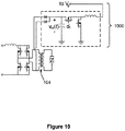
- an electrosurgical generator further comprises a non-dissipative voltage snubber circuit 1000 to prevent undesirable voltage spikes.
- the snubber circuit 1000 may be coupled to an electrosurgical generator such as electrosurgical generator 300 or electrosurgical generator 500.
- the non-dissipative voltage snubber circuit 1000 is coupled to the primary winding of the transformer 104.
- a duty cycle d S of snubber circuit 1000 is varied to maintain v CS (t) at a fixed value.
- instruments used for electrosurgery typically have leads that are several meters long. The long leads can result in an inductive load to the electrosurgical generator. Therefore, snubber circuit 1000 may further be configured to damp voltage spikes generated when switching the inductive load.
- the electrosurgical generator may include any electrosurgical generator control system comprising a mode selector that determines the current operating mode, steering logic that selects from the possible operating modes of constant current, constant power, or constant voltage, where the operating mode is based in part on the outputs of a current mode controller and a voltage mode controller.
- the operating mode and transitions between operating mode are configured to provide near deadbeat control of an electrosurgical generator having both a DC-DC buck converter and a DC-AC boost inverter.
Description
- An electrosurgical generator is commonly used in surgical practice to perform arc cutting and coagulation. The electrosurgical generator produces a high-frequency electric current to cut tissue with limited blood loss and enhanced cutting control compared to a metal blade. Standard industry practice is for electrosurgical generators to measure and average the alternating current (AC) output power over several cycles and use a low-bandwidth control loop to adjust the duty cycle of a pulse width modulated (PWM) converter, modulating the carrier of a fixed-output-impedance resonant inverter to achieve the desired output characteristic. However, the feedback control loop and several cycles average gives rise to latency issues.
- One example of an industry practice is for electrosurgical generators to mimic medium-frequency (MF) amplitude modulated (AM) broadcast transmitters via a method commonly called the Kahn Envelope Elimination and Restoration technique. Such generators typically use a class-D or class-E RF output stage operating with constant voltage amplitude at the electrosurgical analogy of a carrier frequency. In various known embodiments, the generators are combined with an efficient converter power supply amplitude modulator, sometimes referred to as a class-S modulator. The converter power supply amplitude modulator may be configured to regulate the RF output voltage, current, or power dissipated in the tissue load to a desired power versus impedance characteristic called a power curve.
- The assumption of such a technique is that the tissue load changes at rates substantially lower than the audio frequency (AF) band. However, this assumption is not entirely accurate when viewed through the prism of arcing, which is the primary mechanism of cutting and coagulation in electrosurgery. Arcing in electrosurgery can extinguish and re-ignite in the middle of a cycle, and changes in its characteristics can occur on scales much broader than the AF. Therefore, this assumption may be one of convenience more so than fact, since the feedback of RF for purposes of control is well known to be very difficult due to the lag introduced by most common feedback controller techniques.
- The commonly used envelope feedback regulation for electrosurgery is accomplished by measuring and averaging the alternating current (AC) output power and load impedance via voltage and current sensor feedback over many (sometimes hundreds) of cycles. This approach is complex, and its slow response during arcing leads to poor regulation of the AC output power, resulting in undesirable thermal spread or other well known tissue damage such as charring and scarring. Thus, a need exists for an electrosurgical generator that overcomes these and other deficiencies.
Patent documentsGB 2164473A US 2005/004564A1 are representative of the available art. - Using a high frequency inverter to form an arc between the output of an electrosurgical generator and tissue of a patient, a surgeon can induce joule heating in the affected cells; this causes the desired surgical effects of cutting, coagulation, and dissection. In an exemplary embodiment, the electrosurgery utilizes joule heating produced by the electrosurgical generator. The electrosurgical generator produces an accurate power source output characteristic, to which maximum voltage and current limits are added. The voltage and current limits of the electrosurgical generator contribute to the safety of the process. Furthermore, in an exemplary embodiment the voltage and current limits are configured to produce particular tissue effects which may be desirable in various surgical applications.
- In an exemplary embodiment, an electrosurgical generator control system produces constant power output without measuring output voltage or output current, and regulates the output power with substantially deadbeat control. The electrosurgical generator control system performs near deadbeat control by regulating inductor current to a specified value, equal to a reference current. Thus, in an exemplary embodiment, the electrosurgical generator control system achieves a desired inverter output characteristic with an efficient and substantially deadbeat control method for AC output power. Furthermore, an exemplary electrosurgical generator control system switches between operating modes based in part on at least one of a measured output voltage, a measured inductor current, and by observing a duty cycle command generated by the control system. Additionally, an exemplary control system provides the ability to adjust the voltage and current limits and facilitate precision control of desired tissue effects. The desired tissue effects may include at least one of cut depth and the amount of surface hemostatis versus thermal spread.
- Compared to prior art electrosurgical generators, an exemplary electrosurgical generator reduces unintended tissue damage by improving regulation of output power. In accordance with an exemplary embodiment, an electrosurgical generator controls the power during a cycle, and reacts to a change in power if arcing occurs. Voltage sources, especially, demonstrate the tendency to have large, uncontrolled power excursions during normal electrosurgical use. The magnitude of the power excursions may be dependent on various factors. One factor is how far the surgeon is away from the tissue when an arc occurs in the sinusoidal cycle. Furthermore, in the prior art, the current sources may introduce long, unintended arcs, even if distance from the tissue was well controlled. Therefore, in an exemplary embodiment, the electrosurgical generator may be configured to control power within a carrier frequency cycle for full arc and plasma control throughout the cycle. Power control within the duration of a carrier frequency cycle is advantageous over the prior art systems because arcing occurs faster than typical voltage or current detection feedback mechanisms can respond.
- Furthermore, the exemplary electrosurgical generator is less complex than prior art electrosurgical generators. Moreover, it is an objective of this application to present an inverter topology and control algorithm which combines current-mode and voltage-mode control to realize the desired output characteristic of an electrosurgical generator in a markedly simpler and more accurate fashion. By directing which of two conversion stages is to be current-mode controlled, constant power, constant current, and constant voltage outputs can be achieved with excellent regulation and fast transitions.
- In an exemplary embodiment, effective regulation of an electrosurgical generator's output is important to achieving the desired clinical effects. If output power is allowed to exceed the desired value, excessive thermal spread may occur, unnecessarily damaging and scarring tissue and impeding healing. If maximum output voltage exceeds the limiting value, charring of tissue may occur, which is frequently undesirable as it may unnecessarily damage tissue and obscure the surgical field. Use of an exemplary electrosurgical generator control scheme in an electrosurgical generator can provide near-deadbeat regulation of output power. In addition, the electrosurgical generator control scheme tends to assure that thermal spread is minimized by accurately supplying the specified power within a few cycles. Additionally, in various embodiments, fast and accurate regulation provided by the constant voltage mode minimizes unintentional tissue charring. Thus, reduced thermal spread and charring should result in better surgical outcomes by reducing scarring and decreasing healing times.
- A more complete understanding of the present invention may be derived by referring to the detailed description and draft statements when considered in connection with the appendix materials and drawing figures, wherein like reference numbers refer to similar elements throughout the drawing figures, and:
-
FIG. 1 illustrates a schematic of an electrosurgical generator circuit, in accordance with various embodiments; -
FIG. 2 illustrates a graphical representation of desired output characteristics, in accordance with various embodiments; -
FIG. 3 illustrates a schematic of an electrosurgical generator circuit, in accordance with various embodiments; -
FIG. 4 illustrates a schematic of an exemplary electrosurgical generator in constant power output mode, in accordance with various embodiments; -
FIG. 5 illustrates a schematic of an exemplary electrosurgical generator circuit with buck converter and boost inverter control, in accordance with various embodiments; -
FIG. 6 illustrates another graphical representation of desired output characteristics, in accordance with various embodiments; -
FIG. 7 illustrates a schematic of an exemplary buck converter circuit with current-programmed mode control, in accordance with various embodiments; -
FIG. 8 illustrates a graphical representation of the interaction between the nonlinear carrier control current limit and measured inductor current, and the establishing of a corresponding duty cycle, in accordance with various embodiments; -
FIG. 9 illustrates yet another graphical representation of desired output characteristics using duty cycle limits, in accordance with various embodiments; and -
FIG. 10 illustrates a schematic of an exemplary non-dissipative snubber circuit, in accordance with various embodiments. - In accordance with the invention, an electrosurgical generator controller operates with near-deadbeat control to maintain a desired AC output of an electrosurgical generator, which operates in at least one of a constant voltage mode, a constant current mode, and a constant power mode. The mode selection is generally based on the impedance associated with the tissue being cut. Different types of tissue, such as muscle and fat, have different impedances. In terms of electrosurgical operations, constant power output tends to uniformly vaporize tissue, resulting in clean dissection. Whereas constant voltage output tends to explosively vaporize or carbonize tissue ("black coagulation"), and constant current output tends to thermally coagulate tissue without vaporization ("white coagulation"). Carbonization is surgically useful if the surgeon wishes to rapidly destroy surface tissue, and thermal coagulation is regularly coupled with mechanical pressure to seal hepatic or lymphatic vessels shut. However, it is desirable for the surgeon to operate using constant power output and importantly, return to using constant power output as quickly as possible if there is deviation.
- With reference to the schematic shown in
Figure 1 , in an exemplary embodiment, anelectrosurgical generator 100 comprises a DC-DC buck converter 101, a DC-AC boost inverter 102, aninductor 103, atransformer 104, and an electrosurgical generator (ESG)control system 110. In the exemplary embodiment, a DC voltage source Vg is electrically coupled to DC-DC buck converter 101. Furthermore,inductor 103 is electrically coupled between DC-DC buck converter 101 and DC-AC boost inverter 102. The output of DC-AC boost inverter 102 transmits power to the primary winding oftransformer 104, which passes through the secondary winding oftransformer 104 to the load Z. Additionally, the load Z changes because tissue impedances vary, and also changes because the cutting process is an arc process. The impedance of an arc varies as it goes through several "phases" of formation and eventual extinguishment within a carrier frequency cycle. - In an exemplary embodiment,
ESG control system 110 is in communication with both DC-DC buck converter 101 and DC-AC boost inverter 102. TheESG control system 110 is configured to control the duty cycle d1 of DC-DC buck converter 101 and the duty cycle d2 of DC-AC boost inverter 102. Additionally,ESG control system 110 is configured to measure power characteristics ofelectrosurgical generator 100, and controlelectrosurgical generator 100 based at least in part on the measured power characteristics. Examples of the measured power characteristics include the current throughinductor 103 and the voltage at the output of DC-AC boost inverter 102. In various embodiments of control modes,ESG control system 110 controls buckconverter 101 by generating duty cycles based on a combination and/or selection of duty cycle inputs from various controllers depending on the mode of operation (e.g., constant current, constant power, or constant voltage). - With respect to the AC output of the electrosurgical generator, "constant power" is defined to mean the average power delivered in each switching cycle is regulated to a substantially fixed value. Likewise, "constant voltage" and "constant current" are defined as the rms value of the AC voltage or current, respectively, being regulated to a substantially fixed value. The substantially fixed values of the constant power, constant voltage, and constant current may be selected by a user or selected from a lookup table.
ESG control system 110 comprises a current-mode controller 111, a voltage-mode controller 112, amode selector 113, andsteering logic 114.Mode selector 113 compares the output voltage Vout(t) and the inductor current iL(t) to "predetermined limits" (discussed in further detail herein) in order to determine the desired mode of operation ofelectrosurgical generator 100. An exemplary graphical representation of the desired output characteristics is illustrated inFigure 2 . In an exemplary embodiment, as the load impedance increases and causes the voltage to increase, the corresponding increasing output voltage triggers the transitioning of the operating mode from constant current (A) to constant power (B) to constant voltage (C). Similarly, in an exemplary embodiment, as the load impedance decreases and causes the current to increase, the corresponding decreasing output voltage triggers the opposite transitioning from constant voltage (C) to constant power (B) to constant current (A) operating modes. - In various embodiments, a constant power mode may be maintained by varying just the duty cycle of a DC-AC boost inverter. With reference to
Figure 3 , anESG control system 310 comprises a current-mode controller 311, a voltage-mode controller 312, amode selector 313, andsteering logic 314. In this exemplary embodiment, current-mode controller 311 compares the inductor current iL(t) to a control current limit iC. In an exemplary embodiment, the control current limit iC is set by a user, or provided by a look-up table. In an exemplary embodiment, current-mode controller 311 uses a latch circuit to generate a switching waveform δ(t) with a duty cycle d1. The inputs of the latch circuit are the current comparison and a clock signal. In an exemplary embodiment, the switching waveform δ(t) is switched "high" at the start of a switching period if the inductor current iL(t) is lower than control current limit iC. Furthermore, in the exemplary embodiment, the switching waveform δ(t) is switched "low" in response to the inductor current iL(t) exceeding the control current limit iC. In other words, a comparison of the inductor current iL(t) to control current limit iC facilitates adjusting the inductor current iL(t) to match the control current limit iC. For small inductor current ripple, in other words ΔiL << iL, the current-mode controller regulates the inductor current iL(t) to an approximately constant value, substantially equal to control current limit iC. - In various embodiments and with continued reference to
Figure 3 , voltage-mode controller 312 comprises acomparator 321, acompensator 322, and a pulse-width modulator 323. Furthermore, in various embodiments, voltage-mode controller 312 compares the output voltage vout(t) with a reference voltage Vmax atcomparator 321. The output ofcomparator 321 is communicated to compensator 322 which in turn outputs an error signal that drivesPWM 323. In the various embodiments, the output ofcompensator 322 is an input signal toPWM 323, which sets the duty cycle d2 of the signal. - Furthermore, in various embodiments,
mode selector 313 comprises an encoder and performs multiple comparisons. The output voltage vout(t) is compared with a first voltage limit Vlimit_1 to generate "signal a". The output voltage vout(t) is compared with a second voltage limit Vlimit_2 to generate "signal b". Similarly, the inductor current iL(t) is compared with a first current limit Ilimit_1 to generate a "signal c". The inductor current iL(t) is compared with a second current limit Ilimit_2 to generate a "signal d". In one exemplary embodiment and with reference to Table 1, the mode selection is set bymode selector 313 based on the above described comparisons. Table 1 lists comparison outcomes and corresponding mode. In an exemplary embodiment, Table 1 lists a "1" value if the output voltage or inductor current is greater than the compared limit, and a "0" value if the output voltage or inductor current is less than the compared limit. For example, if output voltage vout(t) exceeds both the first voltage limit Vlimit_1 and the second voltage limit Vlimit_2, then the encoder selects the constant voltage mode. Further, the second voltage limit Vlimit_2 is equivalent to reference voltage Vmax, the same used in the comparison at voltage-mode controller 312.Table 1 a b c d Mode 0 0 1 1 I 1 0 1 0 P 1 1 0 0 V - In various embodiments, constant AC power output is achieved by setting duty cycle d1 to a fixed value, and running the DC-AC boost inverter stage as a current-programmed boost inverter by varying duty cycle d2. As previously mentioned,
electrosurgical generator controller 310 performs near deadbeat control by regulating inductor current to an approximately constant value, equal to a control current limit iC. For illustration purposes,Figure 4 represents an exemplary schematic of the electrosurgical generator in constant power output mode. - In steady-state, the average voltage of v1(t) is constant in response to the input voltage Vg being constant, the DC-DC buck converter being bypassed by being set to 100% duty cycle, and no average voltage being able to exist across inductor L. The use of current programmed mode control results in the average current of i1(t) being regulated to an approximately fixed value with deadbeat or near-deadbeat control. In order to regulate i1(t), duty cycle d2 is varied by the current mode controller to maintain i1(t) at a fixed value. Given the fixed voltage v1 and current i1, the power at input of DC-AC boost circuit 102 (i.e., a switch network) is also constant. In an exemplary embodiment, the switch network is nearly lossless, resulting in the output power being approximately equal to the input power. Since the input power is constant, the output power of DC-
AC boost circuit 102 is also constant. - In various embodiments and with renewed reference to
Figure 3 , constant voltage output is achieved by setting duty cycle d1 of DC-DC buck converter 101 to a fixed value, and using voltage-mode control for duty cycle d2 of DC-AC boost circuit 102. In an exemplary embodiment, the voltage-mode control involves measuring the output voltage vout(t) of DC-AC boost circuit 102 with a sensor network, feeding the sensed output voltage vout(t) to a control loop in voltage-mode controller 312, and adjusting the converter's duty cycle command based on the relative difference between the measured output voltage vout(t) and the reference output voltage Vmax. In other words, the duty cycle d2 is set to increase or decrease the output voltage to match Vmax. In an exemplary embodiment, Vmax may be set by a user or based on values in a look-up table. - In an exemplary embodiment, constant current output is achieved by operating DC-
AC boost circuit 102 at a fixed duty cycle d2 and current-mode controlling DC-DC buck converter 101. In an exemplary embodiment, the current-mode control accurately controls the average inductor current such that the output ofbuck converter 101 is a constant current. In one embodiment, current-mode controller 111 compares inductor current iL(t) to control current limit iC, where the control current limit iC is a desired fixed value. In other words,electrosurgical generator controller 310 is configured to vary duty cycle d1 in order to maintain inductor current iL(t) at the fixed value. In various exemplary embodiments, as with vout(t), iL(t) is measured with a sensor and not an estimated value. As a result, the constant current output mode produces an AC output current whose magnitude is regulated with near-deadbeat speed. - In various embodiments, an electrosurgical generator system implementing the three modes of constant power, constant voltage, or constant current produces a very fast, very accurate regulation of the AC output characteristic. Various modes are impacted by measured characteristics, while other modes do not need to respond to the same measured characteristics. Specifically,
electrosurgical generator controller 310 may switch between operating modes based in part on measured output voltage vout(t). Furthermore,electrosurgical generator controller 310 may adjust the operating parameters in the constant voltage mode based on the measured output voltage vout(t). In other words, the selection of which stage of the converter to current-mode control may be achieved with minimal feedback and without a need for extraneous measurements, averaging, or feedback of the output. - Transitioning between the three modes, in an exemplary embodiment, is determined by monitoring the voltage of the primary winding of
transformer 104 and the inductor current. As previously described, in accordance with one exemplary embodiment, the transition from one mode to the next is summarized in Table 1. An exemplary ESG transitions modes from constant current to constant power to constant voltage as the output voltage vout(t) increases. Specifically, in an exemplary embodiment,electrosurgical generator 300 operates in the constant current mode if the output voltage vout(t) is less than a first voltage limit Vlimit_1. If the output voltage vout(t) exceeds the first voltage limit,electrosurgical generator 300 transitions to the constant power mode. If the output voltage vout(t) exceeds a second voltage limit Vlimit_2,electrosurgical generator 300 transitions to the constant voltage mode, where the output voltage vout(t) is limited and held constant. In an exemplary embodiment, the first voltage limit Vlimit_1 and the second voltage limit Vlimit_2 are set by a user or from a look-up table. - Similarly,
electrosurgical generator 300 transitions from constant voltage mode to constant power mode to constant current mode as inductor current iL(t) increases. Specifically, in an exemplary embodiment,electrosurgical generator 300 operates in the constant voltage mode if the inductor current iL(t) does not exceed a first current limit Ilimit_1. If the inductor current iL(t) does exceed the first current limit Ilimit_1, then the mode transitions to the constant power mode. If the inductor current iL(t) exceeds a second current limit Ilimit_2,electrosurgical generator 300 transitions to the constant current mode, where the inductor current iL(t) is limited and held constant. In an exemplary embodiment, the first current limit Ilimit_1 and the second current limit Ilimit_2 are set by a user or from a look-up table. - In accordance with various embodiments and with reference to
Figure 5 , anelectrosurgical generator 500 having anESG control system 510 comprises a current-mode controller 511, a voltage-mode controller 512, amode selector 513, andsteering logic 514. In various embodiments, the operational mode ofelectrosurgical generator 500 is one of constant (or maximum) current Imax, constant power P1 from a buck converter, constant power P2 from boost inverter, or constant (or maximum) voltage Vmax. These modes are illustrated in an exemplary embodiment with reference toFigure 6 . The output selection ofmode selector 513 is communicated tosteering logic 514. In an exemplary embodiment, steeringlogic 514 controls which of at least one of current-mode controller 511 and voltage-mode controller 512 are enabled. Furthermore, steeringlogic 514 may select which conversion stage receives the output of current-mode controller 511 and/or voltage-mode controller 512. In various embodiments, steeringlogic 514 switches between operating either DC-DC buck converter 101 or DC-AC boost inverter 102 with current-mode control for constant power, depending on which portion of constant power regions (P1 or P2) is currently the operating mode. For example, thevoltage mode controller 512 and/orcurrent mode controller 511 may adjust the duty cycles d1 and/or d2 for the operating mode (constant current mode, constant voltage mode, constant power P1, or constant power P2). Furthermore, steeringlogic 514 selects the duty cycle that each of DC-DC buck converter 101 and/or DC-AC boost inverter 102 receives. - In various embodiments, the current-
mode controller 511 compares the inductor current iL(t) to a nonlinear carrier control current limit iC(t). In an exemplary embodiment, the nonlinear carrier control current limit iC(t) is set by the selection of Pset, which may be done by a user, or provided by a look-up table. In an exemplary embodiment, current-mode controller 511 uses a latch circuit to compare inductor current iL(t) to control current limit iC(t), comprising either a current limit signal (I) or a power limit signal (P1). The control signal for a P/I switch is the mode signal, which is communicated frommode selector 513. The inputs of the latch circuit are a clock signal and the comparison of control current limit iC(t) and inductor current iL(t), comprising one of the current limit signal (I) or a power limit signal (P1). The selection of the current-mode controller 511 output is in response to the current mode of theelectrosurgical generator 500. The operating mode of theelectrosurgical generator 500 may be communicated from the output ofmode selector 513. In an exemplary embodiment, the switching waveform δ(t) is switched "high" at the start of a switching period if the inductor current iL(t) is lower than nonlinear carrier control current limit iC(t). Furthermore, in the exemplary embodiment, the switching waveform δ(t) is switched "low" in response to the inductor current iL(t) exceeding the nonlinear carrier control current limit iC(t). In other words, a comparison of the inductor current iL(t) to nonlinear carrier control current limit iC(t) facilitates adjusting pulse duration of buck converter's 101 duty cycle, as previously described. - To generate and control a constant current from
electrosurgical generator 500, the average value of inductor current iL(t) is controlled to be substantially equal to fixed control current limit K*Pset, which is a fixed, non-time varying value. For small inductor current ripple, in other words ΔiL << iL, the current-mode controller regulates the inductor current iL(t) to an approximately constant value, substantially equal to the fixed control current limit. - With respect to using a buck converter to generate substantially constant power (e.g., constant power P1), implementation of a nonlinear carrier control current limit is further described. In addition to generating a constant power source based on varying just the duty cycle of a DC-AC boost inverter, a buck converter may also be configured to generate substantially constant power output. In accordance with various exemplary embodiments, substantially constant power output of a buck converter may be achieved by adjusting a duty cycle's active period for the buck converter. In an exemplary embodiment and with reference to
Figure 7 , a buck converter system comprises a power source Vg, abuck converter circuit 710, acontroller 720, and aload 730. The impedance of the load may be static or dynamic. In the various embodiments, thecontroller 720 receives afeedback signal 711 representative of the output of thebuck converter 710. In an exemplary embodiment, thefeedback signal 711 is a measurement of the current passing through aninductor 712 coupled to buckconverter circuit 710. - In various embodiments,
controller 720 receives real time feedback of the inductor current iL(t) from the buck converter. Thefeedback signal 711 is used bycontroller 720 to adjust the duration of the active and non-active portions of the duty cycle. Adjustment of the duty cycle portions in real time, or substantially in real time, may be configured to produce a constant power source frombuck converter 710. In various embodiments, two characteristics of theinductor feedback signal 711 are used to make the determination of duty cycle adjustments. The two characteristics are, first, the value of inductor current iL(t) and second, the slope of the change in the inductor current iL(t). These two characteristics may be used to provide implied information regarding the current and voltage of the output power intoload 730, and this implied information may be used to adjust the magnitude of the duty cycle in real time and produce substantially constant power output. - The pulse duration of the duty cycle of DC-
DC buck converter 710 is varied usingcurrent mode controller 720. The varying pulse duration of the duty cycle controls the inductor current iL(t), which is responsive to load 730 in contact withbuck converter 710. As the impedance ofload 730 varies, the voltage acrossinductor 712 also varies, and the current throughinductor 712 varies as well. - Described in more detail, at the beginning of the buck converter duty cycle, the active portion (also referred to as the pulse duration of the pulse period or the "on" portion) of the duty cycle is initiated. With respect to a buck converter, the active portion of the pulse period closes a switch between a power source and an inductor, thereby allowing power to flow through the inductor. In various embodiments and with reference to
Figure 8 , the inductor feedback signal iL(t) is compared to a nonlinear carrier control current iC(t). The nonlinear carrier control current iC(t) is a time-varying, nonlinear control signal that may be set for customized uses based on the desired output power. In response to the inductor feedback signal iL(t) exceeding the control current iC(t), the duty cycle switches to the non-active portion (also referred to as the "off' portion). The duty cycle stays in the non-active portion until the end of the pulse period. At the end of the pulse period, the cycle begins again with another pulse duration. - In various embodiments, the switching cycle has a fixed time period. Comparison of the inductor feedback signal iL(t) and the nonlinear carrier control current iC(t) is able to facilitate substantially constant power output based on a variable division of active and non-active portions of the duty cycle. As briefly described and with continued reference to
Figure 8 , the inductor current value and the slope of the change in the inductor current iL(t) are used to adjust the duty cycle. By way of example and without limitation, the inductor current slope affects the timing of how long the inductor current iL(t) is less than the nonlinear carrier control current iC(t). A lower slope value indicates that the inductor current iL(t) is increasing at a slower rate, and therefore it will take a longer period of time until the inductor current iL(t) exceeds the control current iC(t). In other words, the more time is takes for the inductor current iL(t) to exceed the control current iC(t), the longer the corresponding pulse duration. For example, see the comparison between the pulse duration at 2TS and 3TS. A higher slope value of inductor current iL(t) indicates that the inductor current is increasing at a quicker rate, and therefore it will take a shorter period of time until the inductor current iL(t) exceeds the control current limit iC(t). The shorter period of time results in the duty cycle staying in the active portion for a shorter period and having shorter pulse duration. - The nonlinear carrier control current iC(t) is part of a nonlinear carrier control (NLC) technique. In various embodiments, the NLC technique applied to the buck converter is based on a nonlinear time dependent variable, which is the nonlinear carrier. In various embodiments, the nonlinear time dependent variable is determined by the input voltage Vg, period of the switching cycle, and the desired power output. The application of NLC technique and production of substantially constant power output creates a buck converter that is a power source. In other words, the buck converter may implement NLC techniques to generate a fixed amount of power and be a power source. In contrast, prior art use of NLC techniques was typically configured to cause a converter to absorb a fixed amount of power and be a power sink. One of the benefits of using NLC control techniques is that a buck converter in combination with a boost inverter can produce a constant power source over a wider impedance range than using just a boost inverter alone. For example, an electrosurgical generator as described herein is capable of operating over an impedance range of about 64 to 4000 ohms. Using both a boost inverter and buck converter to source constant power facilitates operating over the wide impedance range without unreasonably high peak voltages.
- In accordance with various exemplary methods, producing constant power output in a buck converter with a load having variable resistance includes turning on a switch of the buck converter at the beginning of the duty cycle to initiate a pulse, and monitoring the current through the inductor. The inductor current linearly increases while the buck converter is operating in the active portion of the duty cycle. The exemplary method may further include comparing, at a control circuit, the inductor current iL(t) to a nonlinear carrier control current iC(t), and turning off the switch of the buck converter in response to the magnitude of the inductor current meeting or exceeding the magnitude of the nonlinear carrier control current. In response to turning off the switch of the buck converter, the inductor current ramps down during the non-active portion of the duty cycle. The changing inductor current slope corresponds to the changing impedance of the load, which may be used to adjust the pulse duration of the duty cycle in order to produce substantially constant power output from the buck converter. In various embodiments, the nonlinear carrier control current is derived from the following equation:

- Although a buck converter with substantially constant power output is described in terms of implemention in an electrosurgical generator, such a buck converter may also be implemented in various applications, such as arc welding and gas-discharge lamps (i.e. street lamps).
- In an exemplary embodiment and with renewed reference to
Figure 5 , voltage-mode controller 512 comprises acomparator 521, acompensator 522, and a pulse-width modulator (PWM) 523. Furthermore, in an exemplary embodiment, voltage-mode controller 512 compares the measured output voltage vout(t) with a reference voltage Vmax atcomparator 521. The output ofcomparator 521 is communicated to compensator 522 which in turn outputs an error signal that drivesPWM 523. In the exemplary embodiment, the output ofcompensator 522 is an input signal toPWM 523, which sets the duty cycle d2 of the signal in certain modes. - In various embodiments, constant voltage output may also be achieved by setting duty cycle d1 of DC-
DC buck converter 101 to a fixed value, and limiting the duty cycle d2 of DC-AC boost inverter 102 to a maximum duty cycle dmax. Implementing a duty cycle limit on DC-AC boost inverter 102 during the constant voltage output generally amounts to running DC-AC boost inverter 102 in an open-loop. In various embodiments, limiting the duty cycle d2 of DC-AC boost inverter 102 to a maximum duty cycle dmax results in poorer steady-state output voltage regulation in comparison to mode transitions using direct measurement, but provides the significant advantage of limiting the peak output voltage on a per-cycle basis, with little or no risk of transient overshoot. For various electrosurgical applications, the steady-state value of the maximum output voltage vout(t) is of lesser importance, as it would be unusual to operate in this output mode for any length of time. Per-cycle transient voltage limiting, however, may be highly useful as a means to limit potential undesirable arcing. Additionally, in various embodiments, a maximum duty cycle may be easily varied without the need to linearize an output voltage measurement or tune a compensator, and in this exemplary embodiment no sensor is required on the output since no direct measurement is taken. - Furthermore, configurations such as
exemplary electrosurgical generator 500 may have additional inputs into the mode selection. In another exemplary embodiment and with reference toFigure 5 ,mode selector 513 comprises an encoder and performs multiple comparisons. The output voltage vout(t) is compared with three separate voltage limits (Vlimit_1, Vlimit_2, Vlimit_3) to generate three voltage comparison signals. Similarly, the inductor current iL(t) is compared with three separate current limits (Ilimit_1, Ilimit_2, Ilimit_3) to generate three current comparison signals. With reference toFigure 6 , in various embodiments,mode selector 513 uses the voltage comparison signals and the current comparison signals to determine whetherelectrosurgical generator 500 is operating in the constant current output region (A), the region P1 of the constant power output region (B), the region P2 of the constant power output region (B), or the constant voltage output region (C). Furthermore, the output mode signal frommode selector 513 controls the switch position insteering logic 514. Moreover, the output mode signal frommode selector 513 controls the switch position in current-mode controller 511. For example, if output voltage vout(t) exceeds the first voltage limit Vlimit_1, the second voltage limit Vlimit_2, and the third voltage limit Vlimit_3, then the encoder selects the constant voltage mode. The constant voltage mode signal frommode selector 513 would cause the switches' position ofsteering logic 514 to be "V". As another example, if output voltage vout(t) exceeds the first voltage limit Vlimit_1 but does not exceed the the second voltage limit Vlimit_2, and inductor current iL(t) exceeds first current limit Ilimit_1 and second current limit Ilimit_2, but does exceed Ilimit_3, thenmode selector 513 determines that the operating mode is constant power P1. The constant power P1 mode signal frommode selector 513 would cause the switches' position ofsteering logic 514 to be "P1" as illustrated inFigure 5 and Table 2. The values "1" and "0" represent any fixed value between 0% and 100% that is not closed-loop controlled. In other words, there is no feedback signal actively changing the fixed values represented by "1" and "0".Table 2: Duty cycle of buck and boost conversion stages by operating mode Constant Current Imax Constant Power P1 Constant Power P2 Constant Voltage Vmax Buck Converter ESG controlled with fixed control current limit ESG controlled with nonlinear carrier control current limit 1 1 Boost Inverter 0 0 ESG controlled with fixed control current limit Voltage mode controlled - In an exemplary embodiment, constant AC power output is achieved by setting one or both of duty cycle δ1 and duty cycle δ2 to desired values. Moreover,
electrosurgical generator 500 operates with constant AC power output in either a first constant power region P1 or a second constant power region P2. In various embodiments, the converter switches between generating constant power usingboost inverter 102 orbuck converter 101, depending on the impedance of the load. Moreover, in various embodiments,electrosurgical generator 100 may operate bothboost inverter 102 andbuck converter 101 at the same time, which results in a constant power output having a high voltage and low power. - In steady-state and operating in first constant power region P1, inductor current iL(t) is compared to a nonlinear carrier control current iC(t) in current-
mode controller 511. The pulse duration of the duty cycle of the DC-DC buck converter is varied using thecurrent mode controller 511. The varying pulse duration of the duty cycle controls the inductor current iL(t), which is responsive to the load in contact with the buck converter. As the impedance of the load varies, the voltage across the inductor vL(t) also varies, and the current through the inductor iL(t) varies as well. As previously described, at the beginning of the duty cycle, the active portion of the duty cycle is initiated. In response to the inductor current iL(t) exceeding the nonlinear carrier control current iC(t), the duty cycle switches to the non-active portion. The duty cycle stays in the non-active portion until the end of the duty cycle, upon which the next duty cycle begins in the active portion. In alternative embodiments, during the comparison of the inductor feedback signal iL(t) and the nonlinear carrier control current iC(t), once the control current exceeds the inductor current, the duty cycle switches to the active portion. In accordance with the exemplary embodiment,electrosurgical generator 500 generates constant power usingbuck converter 101 during first constant power region P1. - In steady-state and operating in second constant power region P2, the average voltage of v1(t) is constant in response to the input voltage Vg being constant, the DC-DC buck converter being bypassed by being set to 100% duty cycle, and no average voltage being able exist across
inductor 103. The use of current programmed mode control results in the average current of i1(t) being regulated to an approximately fixed value with deadbeat or near-deadbeat control. In order to regulate i1(t), duty cycle δ2 is varied by the current mode controller to maintain i1(t) at a fixed value. Given the fixed voltage and current, the power at input of DC-AC boost inverter (i.e., a switch network) is also constant. In an exemplary embodiment, the switch network is nearly lossless, resulting in the output power being approximately equal to the input power. Since the input power is constant, the output power of DC-AC boost inverter 102 is also constant. - In an exemplary embodiment, constant voltage output is achieved by setting duty cycle δ1 of DC-
DC buck converter 101 to a fixed value, and duty cycle δ2 of DC-AC boost inverter 102 is voltage-mode controlled. In an exemplary embodiment, the voltage-mode control involves measuring the output voltage vout(t) of DC-AC boost inverter 102 with a sensor, feeding the sensed output voltage to a control loop in voltage-mode controller 512, and adjusting the converter's duty cycle command based on the relative difference between the measured output voltage and the reference output voltage. In other words, the duty cycle δ2 is set to increase or decrease the output voltage to match Vmax. In an exemplary embodiment, Vmax may be set by a user or based on values in a look-up table. In an alternative embodiment, the boost inverter is run at a fixed duty cycle with no feedback of the output voltage. - In an exemplary embodiment, constant current output is achieved by operating DC-
AC boost inverter 102 at a fixed duty cycle δ2 and current-mode controlling DC-DC buck converter 101. In an exemplary embodiment, the current-mode control accurately controls the average inductor current such that the output ofbuck converter 101 is a constant current. In one constant current embodiment, current-mode controller 511 compares inductor current iL(t) to a control current limit iC(t). In various embodiments, control current limit iC(t) may be a selected, fixed value or may be set by K*Pset, where K*Pset is a constant current set by the user during use. In various embodiments, Pset is set during the design stage. In other words,ESG control system 510 is configured to vary duty cycle δ1 in order to maintain inductor current iL(t) at the fixed value. As a result, the constant current output mode produces an AC output current whose magnitude is regulated with near-deadbeat speed. - Similar to the transition of modes in
electrosurgical generator 300, in an exemplary embodiment,electrosurgical generator 500 also implements the three modes of constant power, constant voltage, or constant current to produce a very fast, very accurate regulation of the AC output characteristic. Various modes are impacted by measured characteristics, while other modes do not need to respond to the same measured characteristics. Specifically,ESG control system 510 switches between operating modes based in part on measured characteristics, such as inductor current and voltage. In other words, the selection of which stage of the converter to current-mode control is achieved with minimal feedback and without a need for extraneous measurements, averaging, or feedback of the output. Also, and as previously mentioned, theESG control system 510 performs near deadbeat control by regulating inductor current to an approximately constant value, equal to a reference current. - Transitioning between the three modes, in an exemplary embodiment, is determined by monitoring the voltage of the primary winding of
transformer 104 and the inductor current. Furthermore, the determination of transitioning between the modes may also based on the voltage and current of the primary winding oftransformer 104. In various embodiments,ESG control system 510 transitions modes from constant current to constant power to constant voltage as the output voltage vout(t) increases. - Specifically, in various embodiments,
electrosurgical generator 500 operates in the constant current mode if the output voltage vout(t) is less than a first voltage limit (Vlimit_1). If the output voltage vout(t) exceeds the first voltage limit,electrosurgical generator 500 transitions to a first constant power mode (P1). If the output voltage vout(t) exceeds a second voltage limit (Vlimit_2),electrosurgical generator 500 transitions to a second constant power mode (P2). If the output voltage vout(t) exceeds a third voltage limit (Vlimit_3),electrosurgical generator 500 transitions to the constant voltage mode, where the output voltage vout(t) is limited and held constant. In an exemplary embodiment, the first voltage limit (Vlimit_1), the second voltage limit (Vlimit_2), and the third voltage limit (Vlimit_3) are set by a user or from a look-up table. - Moreover, an exemplary
ESG control system 510 transitions from constant voltage mode to constant power mode to constant current mode as inductor current iL(t) increases. Specifically, in an exemplary embodiment,electrosurgical generator 500 operates in the constant voltage mode if the inductor current iL(t) does not exceed a first current limit (Ilimit_1). If the inductor current iL(t) does exceed the first current limit (Ilimit_1), then the mode transitions to the second constant power mode (P2). If the inductor current iL(t) exceeds a second current limit (Ilimit_2), then the mode transitions to the first constant power mode (P1). If the inductor current iL(t) exceeds a third current limit (Ilimit_3),electrosurgical generator 500 transitions to the constant current mode, where the inductor current iL(t) is limited and held constant. In an exemplary embodiment, the first current limit (Ilimit_1), the second current limit (Ilimit_2), and the third current limit (Ilimit_3) are set by a user or from a look-up table. - In various alternative embodiments, the selection of operating modes may be based in part on the duty cycle. For example, if the electrosurgical generator is operating in constant power mode using the buck converter and the duty cycle reaches 100% active, the controller may be configured to switch to the constant power mode using the boost inverter. The switch to the boost inverter enables the electrosurgical generator to operate over a higher range of impedances.
- In various embodiments, duty cycle limits may be used in the electrosurgical generator controller to control the mode transitions. With reference to
Figure 9 , in various embodiments, an exemplary mode selector may use duty cycle comparison signals to determine whetherelectrosurgical generator 500 is operating in the constant current output region (A), the region P1 of the constant power output region (B), the region P2 of the constant power output region (B), or the constant voltage output region (C). - In an exemplary embodiment, the duty cycle comparison signals are generated from the comparison of the buck converter duty cycle dbuck (also referred to as d1 herein) and the boost inverter duty cycle dboost (also referred to as d2 herein) to at least four separate duty cycle limits (dlimit_1, dlimit_2, dlimit_3, and dlimit_4). For example, if the buck converter duty cycle dbuck exceeds the first duty cycle limit dlimit_1 and the second duty cycle limit dlimit_2, and also the boost inverter duty cycle dboost exceeds the third duty cycle limit dlimit_3, then the electrosurgical generator operates in the constant voltage mode and constant voltage output region (C). Similarly, if the boost inverter duty cycle dboost is less than the third duty cycle limit dlimit_3, and the fourth duty cycle limit dlimit_4, and the buck converter duty cycle dbuck is less than the first duty cycle limit dlimit_1, then the electrosurgical generator operates in the constant current mode and constant current output region (A). Further, as is illustrated in
Figure 9 , the duty cycle comparison signals may also result in the electrosurgical generator operating in the region P1 of the constant power output region (B), or the region P2 of the constant power output region (B). Therefore, in one exemplary embodiment,mode selector 513 is configured to determine the operating mode basd at least in part on comparisons of the buck converter duty cycle dbuck and boost inverter duty cycle dboost to the duty cycle limits and to generate mode output signals to controlsteering logic 514 and/orcurrent mode controller 511. - In accordance with an exemplary embodiment, both the current-
mode control 311 and the current-mode controller 511 may be able to maintain an approximately constant value of inductor current iL(t) by adjusting the current within 1-2 cycles. In another exemplary embodiment, the current-mode controller adjusts the inductor current within 1-10 cycles. In yet another embodiment, the current-mode controller adjusts the inductor within 10-100 cycles. Any of these examples may comprise a "low cycle" adjustemtn. This low cycle adjustment can be considered "deadbeat control" or "near-deadbeat control". In accordance with an exemplary embodiment, near-deadbeat control minimizes unintentional charring by ensuring that only the requested quantum of power is delivered to the electrosurgical instrument. In the prior art, slow transient response of the converter to changes in load impedance may result in excessive delivery of power that may not be detected for 500 cycles or more. Stated another way, in an exemplary embodiment, an electrosurgical generator has an operating bandwidth of 100-500 kHz, compared to the prior art bandwidth of 1-10 kHz. - Although the mode transitions operate with near-deadbeat control, it still takes at least 1-2 cycles to change modes, and in some embodiments up to 100 cycles. Thus, should the load impedance suddenly increase while in either constant power mode, the converter will continue to supply constant power for the remainder of at least one cycle before transitioning to the constant voltage mode. In accordance with an exemplary embodiment and with reference to
Figure 10 , an electrosurgical generator further comprises a non-dissipativevoltage snubber circuit 1000 to prevent undesirable voltage spikes. Thesnubber circuit 1000 may be coupled to an electrosurgical generator such aselectrosurgical generator 300 orelectrosurgical generator 500. The non-dissipativevoltage snubber circuit 1000 is coupled to the primary winding of thetransformer 104. In an exemplary embodiment, a duty cycle dS ofsnubber circuit 1000 is varied to maintain vCS(t) at a fixed value. Furthermore, instruments used for electrosurgery typically have leads that are several meters long. The long leads can result in an inductive load to the electrosurgical generator. Therefore,snubber circuit 1000 may further be configured to damp voltage spikes generated when switching the inductive load. - In general, any number of current, voltage, or duty cycle limits, and any number of subdivisions of constant current, constant power, or constant voltage modes may be used to facilitate operating mode selection and transition in order to provide near deadbeat control of an electrosurgical generator. The electrosurgical generator may include any electrosurgical generator control system comprising a mode selector that determines the current operating mode, steering logic that selects from the possible operating modes of constant current, constant power, or constant voltage, where the operating mode is based in part on the outputs of a current mode controller and a voltage mode controller. The operating mode and transitions between operating mode are configured to provide near deadbeat control of an electrosurgical generator having both a DC-DC buck converter and a DC-AC boost inverter.
- Failure to maintain either accurate regulation of output power or sufficient means of voltage limiting may lead to higher output voltages, leading to unintentional charring, or higher output power, leading to unintentional thermal spread. The exemplary embodiments of the electrosurgical generators described herein accurately and quickly maintain the proper power characteristics, and allow a user to control the cutting process.
- Furthermore, one or more of the following numbered clauses may describe and relate to further aspects or features within the contest od the present teaching:
- 1. An electrosurgical generator comprising:
- a DC-DC buck converter configured to receive input power;
- an inductor in communication with the DC-DC buck converter and a DC-AC boost inverter;
- a transformer having a primary winding and a secondary winding, wherein the transformer is configured to transmit output power to a load;
- wherein the DC-AC boost inverter is configured to receive an input from the inductor and transfer AC power to the primary winding of the transformer;
- an electrosurgical generator (ESG) controller configured to control both the DC-DC buck converter and the DC-AC boost inverter, wherein control is based in part on electrical parameters of the electrosurgical generator.
- 2. The electrosurgical generator of
clause 1, wherein the electrical parameters include the inductor current or the voltage of the AC power from the DC-AC boost inverter. - 3. The electrosurgical generator of
clause 1 orclause 2, wherein the electrosurgical generator is configured to operate within selected voltage and current limits. - 4. The electrosurgical generator of any preceding clause, wherein the electrosurgical generator operates in three modes, wherein the selection of the mode is in response to changes in the impedance of the load.
- 5. The electrosurgical generator of clause 4, wherein the three modes include a constant voltage mode, a constant current mode, and a constant power mode.
- 6. The electrosurgical generator of
clause 1, wherein the ESG controller comprises:- a current-mode controller configured to compare an inductor current iL(t) to a control current limit iC(t);
- a voltage-mode controller configured to compare the output voltage vout(t) with a reference voltage Vmax;
- a mode selector configured to determine an operating mode based on predetermined limits and generate an operating mode indicator; and
- steering logic configured to receive the operating mode indicator and facilitate the selection of the operating mode by the ESG controller.
- 7. The electrosurgical generator of clause 6, wherein the predetermined limits include voltage limits and current limits.
- 8. The electrosurgical generator of clause 6, wherein the predetermined limits include duty cycle limits.
- 9. The electrosurgical generator of any preceding clause, wherein the electrosurgical generator operates with substantially deadbeat control.
- 10. The electrosurgical generator of clause 10, wherein the substantially deadbeat control is deadbeat control within at least one of 1-2 cycles, 1-10 cycles, and 10-100 cycles.
- 11. The electrosurgical generator of clause 10, wherein the substantially deadbeat control has an operating bandwidth of 100-500 kHz.
- 12. An electrosurgical generator (ESG) controller of an electrosurgical generator, wherein the ESG controller comprises:
- a current-mode controller configured to compare an inductor current iL(t) to a control current limit iC(t), and wherein the current-mode controller is configured generate a switching waveform δ(t) with a first duty cycle d1;
- a voltage-mode controller configured to compare the output voltage vout(t) with a reference voltage Vmax, and wherein the voltage-mode controller is configured to generate a second duty cycle d2 for facilitating a constant voltage mode of the electrosurgical generator;
- a mode selector configured to compare signal inputs and generate an operating mode indicator; and
- steering logic configured to receive the operating mode indicator and facilitate the selection of the operating mode by the ESG controller,
- wherein the steering logic provides two duty cycle signals to the electrosurgical generator;
- wherein the steering logic is further configured to facilitate selection of the operating mode by providing the two duty cycle signals based on various combinations of the first duty cycle d1, the second duty cycle d2, and two fixed value duty cycles.
- 13. The ESG controller of clause 12, wherein the control current limit iC(t) is set by a user or provided by a look-up table.
- 14. The ESG controller of clause 12, wherein the comparison of the inductor current iL(t) to reference current limit iC(t) facilitates adjusting the inductor current iL(t) to match the reference current limit iC(t).
- 15. The ESG controller of clause 12, wherein the voltage-mode controller comprises a comparator, a compensator, and a pulse-width modulator (PWM), wherein the voltage-mode controller compares the output voltage Vout(t) with the reference voltage Vmax at the comparator, and wherein the output of the comparator is communicated to the compensator, and wherein the compensator outputs an error signal that drives the PWM, and wherein the PWM generates the second duty cycle d2.
- Benefits, other advantages, and solutions to problems have been described above with regard to specific embodiments. However, the benefits, advantages, solutions to problems, and any element(s) that may cause any benefit, advantage, or solution to occur or become more pronounced are not to be construed as critical, required, or essential features or elements of any or all the draft statements. As used herein, the terms "includes," "including," "comprises," "comprising," or any other variation thereof, are intended to cover a non-exclusive inclusion, such that a process, method, article, or apparatus that comprises a list of elements does not include only those elements but may include other elements not expressly listed or inherent to such process, method, article, or apparatus. Further, no element described herein is required for the practice of the invention unless expressly described as "essential" or "critical."
Claims (15)
- An electrosurgical generator, ESG, controller of an electrosurgical generator, wherein the ESG controller comprises:a current-mode controller configured to compare an inductor current iL(t) to a control current limit ic, and wherein the current-mode controller is configured generate a current-mode controller signal for use during either a constant current operating mode of the ESG or a constant power operating mode of the ESG;a voltage-mode controller configured to compare an output voltage vout(t) with a reference voltage Vmax, and wherein the voltage-mode controller is configured to generate a voltage-mode controller signal for use during a constant voltage operating mode of the ESG;a mode selector configured to compare the inductor current iL(t) and the output voltage vout(t) to respective current limits and voltage limits and to generate an operating mode indicator; andsteering logic configured to receive the operating mode indicator and select an operating mode from one of the constant current operating mode of the ESG or the constant power operating mode of the ESG or the constant voltage operating mode of the ESG, wherein the steering logic is configured to provide a first signal to the electrosurgical generator at a first controller output and a second signal to the electrosurgical generator at a second controller output based on the operating mode indicator.
- The ESG controller of claim 1, wherein the current-mode controller signal has a first duty cycle d1, wherein the current-mode controller is configured to compare the inductor current iL(t) to the control current limit ic, that is set by a user or provided by a look-up table, and to adjust the first duty cycle d1 of the current-mode controller signal to maintain a constant iL(t).
- The ESG controller of claim 1, wherein the comparison of the inductor current iL(t) to the control current limit ic is used to adjust the current-mode controller signal to cause the inductor current iL(t) to match the control current limit ic.
- The ESG controller of claim 1, wherein the voltage-mode controller comprises a comparator, a compensator, and a pulse-width modulator, PWM, wherein the voltage-mode controller is configured to compare the output voltage vout(t) with the reference voltage Vmax at the comparator, and wherein an output of the comparator is communicated to the compensator, and wherein the compensator outputs an error signal that drives the PWM, and wherein the PWM generates the second signal.
- The ESG controller of claim 1, wherein the current-mode controller signal has a duty cycle, d1, and the voltage-mode controller signal has a duty cycle, d2, and wherein the steering logic is further configured to select the operating mode by providing the first signal and the second signal based on various combinations of the current-mode controller signal, the voltage-mode controller signal, a third signal having a fixed duty cycle, and a fourth signal having a fixed duty cycle.
- The ESG controller of claim 5, wherein the steering logic is configured:to provide the first signal based on the current-mode controller signal and to provide the second signal based on the fourth signal, during the constant current operating mode of the ESG;to provide the first signal based on the third signal and to provide the second signal based on the current-mode controller signal during the constant power operating mode; andto provide the first signal based on the third signal and to provide the second signal based on the voltage-mode controller signal during the constant voltage operating mode.
- The ESG controller of claim 5, wherein the steering logic is configured:to provide the first signal based on the current-mode controller signal and to provide the second signal based on the fourth signal, during the constant current operating mode of the ESG;to provide the first signal based on the current-mode controller signal and to provide the second signal based on the fourth signal, during a first constant power operating mode of the ESG;to provide the first signal based on the third signal and to provide the second signal based on the current-mode controller signal during a second constant power operating mode; andto provide the first signal based on the third signal and to provide the second signal based on the voltage-mode controller signal during the constant voltage operating mode;wherein the current-mode controller signal is based on a comparison of the inductor current iL(t) to a value equal to K*Pset during the constant current operating mode and based on a comparison of the inductor current iL(t) to a nonlinear time dependent variable during the first constant power operating mode.
- The ESG controller of claim 1,
wherein the current-mode controller signal has a first duty cycle d1,
wherein the voltage-mode controller signal has a second duty cycle d2,
wherein the first duty cycle d1 is based on the current-mode controller signal during the constant current operating mode,
wherein the first duty cycle d1 is a fixed value x% on during the constant power operating mode or constant voltage mode,
wherein the second duty cycle d2 is based on the voltage-mode controller signal during the constant voltage operating mode,
wherein the second duty cycle d2 is a fixed value y% on during the constant current operating mode, and
wherein the second duty cycle d2 is based on the current-mode controller signal during the constant power operating mode. - The ESG controller of claim 8, wherein x=100 and y=0.
- A method of controlling an electrosurgical generator, ESG, comprising
comparing an inductor current iL(t) to a control current limit ic, to generate a current-mode controller signal for use during either a constant current operating mode of the ESG or a constant power operating mode of the ESG;
comparing an output voltage, vout(t), with a reference voltage, Vmax, to generate a voltage-mode controller signal for use during a constant voltage operating mode of the ESG;
comparing the inductor current iL(t) and the output voltage, vout(t), to respective current limits and voltage limits to generate an operating mode indicator; and
using steering logic to receive the operating mode indicator and select an operating mode from one of the constant current operating mode of the ESG or the constant power operating mode of the ESG or the constant voltage operating mode of the ESG, and to provide a first signal to the electrosurgical generator at a first controller output and a second signal to the electrosurgical generator at a second controller output based on the operating mode indicator. - The method of claim 10, further comprising adjusting the current-mode controller signal to cause the inductor current iL(t) to match the control current limit ic.
- The method of claim 11, wherein the selecting further comprises:outputting the first signal based on the current-mode controller signal and outputting the second signal based on a fourth signal having a fixed duty cycle, during the constant current operating mode of the ESG;outputting the first signal based on a third signal having a fixed duty cycle and outputting the second signal based on the current-mode controller signal, during the constant power operating mode; andoutputting the first signal based on the third signal and outputting the second signal based on the voltage-mode controller signal, during the constant voltage operating mode.
- The method of claim 10, wherein the generating the current-mode controller signal further comprises one of:generating the current-mode controller signal based on a comparison of the inductor current iL(t) to a constant current value, during the constant current operating mode; andgenerating the current-mode controller signal based on a comparison of the inductor current iL(t) a nonlinear time dependent variable, during a first constant power operating mode.
- The method of claim 13, wherein the selecting further comprises:outputting the first signal based on the current-mode controller signal and outputting the second signal based on a fourth signal having a fixed duty cycle, during the constant current operating mode of the ESG;outputting the first signal based on the current-mode controller signal and outputting the second signal based on the fourth signal, during the first constant power operating mode of the ESG;outputting the first signal based on a third signal having a fixed duty cycle and outputting the second signal based on the current-mode controller signal, during a second constant power operating mode; andoutputting the first signal based on the third signal and outputting the second signal based on the voltage-mode controller signal, during the constant voltage operating mode.
- The method of claim 10, wherein one of:(a) outputting the first signal based on a third signal having a fixed duty cycle and outputting the second signal based on the current-mode controller signal, during a single constant power operating mode of the ESG; and(b) outputting the first signal based on the current-mode controller signal and outputting the second signal based on a fourth signal having a fixed duty cycle, during a first constant power operating mode, outputting the first signal based on the third signal and outputting the second signal based on the current-mode controller signal, during a second constant power operating mode, wherein the current-mode controller signal is based on a comparison of the inductor current iL(t) to a nonlinear time dependent variable during the first constant power operating mode, and wherein the current-mode controller signal is based on a comparison of the inductor current iL(t) to the control current limit ic during the second constant power operating mode.
Applications Claiming Priority (4)
| Application Number | Priority Date | Filing Date | Title |
|---|---|---|---|
| US201061426985P | 2010-12-23 | 2010-12-23 | |
| US201161530528P | 2011-09-02 | 2011-09-02 | |
| US13/334,041 US9379643B2 (en) | 2010-12-23 | 2011-12-21 | Electrosurgical generator controller for regulation of electrosurgical generator output power |
| EP11195600.9A EP2469699B1 (en) | 2010-12-23 | 2011-12-23 | Electrosurgical generator with regulated output power |
Related Parent Applications (2)
| Application Number | Title | Priority Date | Filing Date |
|---|---|---|---|
| EP11195600.9A Division-Into EP2469699B1 (en) | 2010-12-23 | 2011-12-23 | Electrosurgical generator with regulated output power |
| EP11195600.9A Division EP2469699B1 (en) | 2010-12-23 | 2011-12-23 | Electrosurgical generator with regulated output power |
Publications (2)
| Publication Number | Publication Date |
|---|---|
| EP3035518A1 EP3035518A1 (en) | 2016-06-22 |
| EP3035518B1 true EP3035518B1 (en) | 2020-04-08 |
Family
ID=45464345
Family Applications (2)
| Application Number | Title | Priority Date | Filing Date |
|---|---|---|---|
| EP16151586.1A Active EP3035518B1 (en) | 2010-12-23 | 2011-12-23 | Electrosurgical generator controller for regulation of electrosurgical generator output power |
| EP11195600.9A Not-in-force EP2469699B1 (en) | 2010-12-23 | 2011-12-23 | Electrosurgical generator with regulated output power |
Family Applications After (1)
| Application Number | Title | Priority Date | Filing Date |
|---|---|---|---|
| EP11195600.9A Not-in-force EP2469699B1 (en) | 2010-12-23 | 2011-12-23 | Electrosurgical generator with regulated output power |
Country Status (5)
| Country | Link |
|---|---|
| US (2) | US9379643B2 (en) |
| EP (2) | EP3035518B1 (en) |
| JP (2) | JP6005934B2 (en) |
| AU (2) | AU2011265566B2 (en) |
| CA (1) | CA2762649A1 (en) |
Families Citing this family (44)
| Publication number | Priority date | Publication date | Assignee | Title |
|---|---|---|---|---|
| CN104604337B (en) * | 2012-09-07 | 2016-05-18 | 株式会社京三制作所 | The control method of continuous-current plant and continuous-current plant |
| GB2508176A (en) * | 2012-11-11 | 2014-05-28 | Univ Liverpool | Plasma generator RF frequency control tracking plasma resonance with adjustable frequency offset for power regulation |
| JP5617909B2 (en) * | 2012-12-12 | 2014-11-05 | トヨタ自動車株式会社 | Converter device |
| US9270202B2 (en) * | 2013-03-11 | 2016-02-23 | Covidien Lp | Constant power inverter with crest factor control |
| US10842563B2 (en) * | 2013-03-15 | 2020-11-24 | Covidien Lp | System and method for power control of electrosurgical resonant inverters |
| US9283028B2 (en) * | 2013-03-15 | 2016-03-15 | Covidien Lp | Crest-factor control of phase-shifted inverter |
| US9482658B2 (en) | 2013-03-25 | 2016-11-01 | Ohio University | Test system and method for determining thermal effects of tissue ablation on an ex vivo tissue |
| GB2514100B (en) * | 2013-05-08 | 2020-04-01 | Creo Medical Ltd | Apparatus for Controlling Power Delivered by Electrosurgical Probe |
| US9559594B2 (en) | 2013-06-24 | 2017-01-31 | Covidien Lp | Dead-time optimization of resonant inverters |
| US10729484B2 (en) * | 2013-07-16 | 2020-08-04 | Covidien Lp | Electrosurgical generator with continuously and arbitrarily variable crest factor |
| US10610285B2 (en) * | 2013-07-19 | 2020-04-07 | Covidien Lp | Electrosurgical generators |
| US9872719B2 (en) * | 2013-07-24 | 2018-01-23 | Covidien Lp | Systems and methods for generating electrosurgical energy using a multistage power converter |
| CA2860197C (en) * | 2013-09-24 | 2021-12-07 | Covidien Lp | Systems and methods for improving efficiency of electrosurgical generators |
| US9839469B2 (en) * | 2013-09-24 | 2017-12-12 | Covidien Lp | Systems and methods for improving efficiency of electrosurgical generators |
| US9770283B2 (en) | 2013-09-24 | 2017-09-26 | Covidien Lp | Systems and methods for improving efficiency of electrosurgical generators |
| JP5729732B2 (en) * | 2013-09-27 | 2015-06-03 | 株式会社京三製作所 | DC power supply and control method of DC power supply |
| JP5679241B1 (en) * | 2013-09-27 | 2015-03-04 | 株式会社京三製作所 | Voltage source DC power supply and control method for voltage source DC power supply |
| US10188446B2 (en) | 2013-10-16 | 2019-01-29 | Covidien Lp | Resonant inverter |
| US9642670B2 (en) | 2013-10-29 | 2017-05-09 | Covidien Lp | Resonant inverter with a common mode choke |
| US10237962B2 (en) | 2014-02-26 | 2019-03-19 | Covidien Lp | Variable frequency excitation plasma device for thermal and non-thermal tissue effects |
| EP2977848B1 (en) * | 2014-07-23 | 2018-02-14 | DET International Holding Limited | Impedance compensation |
| CN104242623B (en) * | 2014-09-05 | 2017-11-07 | 中南民族大学 | A kind of quick start method of Switching Power Supply and quick start control circuit |
| WO2016070013A1 (en) * | 2014-10-31 | 2016-05-06 | Medtronic Advanced Energy Llc | Fingerswitch circuitry to reduce rf leakage current |
| US11090106B2 (en) * | 2015-04-23 | 2021-08-17 | Covidien Lp | Control systems for electrosurgical generator |
| CZ306263B6 (en) * | 2015-05-19 | 2016-11-02 | Compex spol. s r.o. | Portable device, intended especially for electrofulguration and electrodessication |
| US9806683B2 (en) * | 2015-06-18 | 2017-10-31 | Crestron Electronics, Inc. | Average current-mode feedback control of multi-channel class-D audio amplifier |
| US9853545B2 (en) | 2015-06-30 | 2017-12-26 | Microsoft Technology Licensing, Llc | Power regulator having current and voltage modes |
| US9839470B2 (en) * | 2015-06-30 | 2017-12-12 | Covidien Lp | Electrosurgical generator for minimizing neuromuscular stimulation |
| US11446078B2 (en) * | 2015-07-20 | 2022-09-20 | Megadyne Medical Products, Inc. | Electrosurgical wave generator |
| KR101771821B1 (en) * | 2015-12-23 | 2017-08-25 | 삼성전기주식회사 | Non-contact type power transmission apparatus |
| US10537377B2 (en) | 2016-05-10 | 2020-01-21 | Covidien Lp | Electrosurgical generator with half-cycle power regulation |
| US10188449B2 (en) | 2016-05-23 | 2019-01-29 | Covidien Lp | System and method for temperature enhanced irreversible electroporation |
| GB2555679A (en) * | 2016-08-05 | 2018-05-09 | Cirrus Logic Int Semiconductor Ltd | Configurable control loop topology for a pulse width modulation amplifier |
| US10193505B2 (en) | 2016-08-05 | 2019-01-29 | Cirrus Logic, Inc. | Configurable control loop topology for a pulse width modulation amplifier |
| US11006997B2 (en) | 2016-08-09 | 2021-05-18 | Covidien Lp | Ultrasonic and radiofrequency energy production and control from a single power converter |
| CN106491202B (en) * | 2016-12-18 | 2023-06-02 | 杭州电子科技大学 | Low-temperature plasma ablation operation system |
| JP6805202B2 (en) | 2018-04-20 | 2020-12-23 | 株式会社京三製作所 | DC / DC converter and DC / DC converter control method |
| JP6805201B2 (en) * | 2018-04-20 | 2020-12-23 | 株式会社京三製作所 | DC / DC converter and DC / DC converter control method |
| US11660449B2 (en) * | 2018-06-11 | 2023-05-30 | Aigain Beauty Ltd. | Artificial intelligence for improved skin tightening |
| CA3060468A1 (en) * | 2018-10-29 | 2020-04-29 | Nuctech Company Limited | Filament power supply for electron accelerator and electron accelerator |
| US10862388B1 (en) | 2019-07-11 | 2020-12-08 | Apple Inc. | Current mode power converter with transient response compensation |
| US11660135B2 (en) | 2019-12-05 | 2023-05-30 | Biosense Webster (Israel) Ltd. | Generating and interleaving of irreversible-electroporation and radiofrequnecy ablation (IRE/RFA) waveforms |
| CN113262038B (en) * | 2021-06-19 | 2024-04-16 | 安徽奥弗医疗设备科技股份有限公司 | Plasma scalpel power control system |
| WO2022269104A1 (en) * | 2021-06-22 | 2022-12-29 | Ingeteam Power Technology, S.A. | Control method and system for dc/ac converters |
Citations (1)
| Publication number | Priority date | Publication date | Assignee | Title |
|---|---|---|---|---|
| US20070176584A1 (en) * | 2005-11-01 | 2007-08-02 | Xiaoping Chen | RV converter with current mode and voltage mode switching |
Family Cites Families (11)
| Publication number | Priority date | Publication date | Assignee | Title |
|---|---|---|---|---|
| US4727874A (en) | 1984-09-10 | 1988-03-01 | C. R. Bard, Inc. | Electrosurgical generator with high-frequency pulse width modulated feedback power control |
| DE59209932D1 (en) | 1991-08-12 | 2001-12-20 | Storz Karl Gmbh & Co Kg | HIGH FREQUENCY SURGERY GENERATOR FOR CONTROLLED CUTTING AND COAGULATION |
| JP3363070B2 (en) | 1997-06-30 | 2003-01-07 | 株式会社東芝 | Power converter |
| DE10218895B4 (en) | 2002-04-26 | 2006-12-21 | Storz Endoskop Produktions Gmbh | High-frequency surgical generator |
| US6979987B2 (en) | 2002-11-14 | 2005-12-27 | Fyre Storm, Inc. | Method of regulating an output voltage of a power converter by sensing the output voltage during a first time interval and calculating a next current value in an inductor sufficient to bring the output voltage to a target voltage within a second time interval immediately following the first time interval and varying a duty cycle of a switch during the second time interval |
| EP1617776B1 (en) | 2003-05-01 | 2015-09-02 | Covidien AG | System for programing and controlling an electrosurgical generator system |
| US7324354B2 (en) | 2005-07-08 | 2008-01-29 | Bio-Rad Laboratories, Inc. | Power supply with a digital feedback loop |
| JP2007288851A (en) * | 2006-04-13 | 2007-11-01 | Ricoh Co Ltd | Maximum duty control circuit, and dc-dc converter and electronic equipment employing it |
| CN101904080B (en) | 2007-12-20 | 2013-06-19 | 松下电器产业株式会社 | Power conversion device, switch device and method for controlling power conversion device |
| JP5704676B2 (en) | 2008-06-25 | 2015-04-22 | 住友重機械工業株式会社 | Hybrid work machine |
| DE102008058737B4 (en) | 2008-09-08 | 2019-12-12 | Erbe Elektromedizin Gmbh | Electrosurgical generator |
-
2011
- 2011-12-21 US US13/334,041 patent/US9379643B2/en active Active
- 2011-12-22 CA CA2762649A patent/CA2762649A1/en not_active Abandoned
- 2011-12-22 JP JP2011281839A patent/JP6005934B2/en not_active Expired - Fee Related
- 2011-12-23 EP EP16151586.1A patent/EP3035518B1/en active Active
- 2011-12-23 EP EP11195600.9A patent/EP2469699B1/en not_active Not-in-force
- 2011-12-23 AU AU2011265566A patent/AU2011265566B2/en not_active Ceased
-
2015
- 2015-07-15 AU AU2015204314A patent/AU2015204314B2/en not_active Ceased
-
2016
- 2016-06-24 US US15/192,870 patent/US9877772B2/en active Active
- 2016-09-08 JP JP2016175275A patent/JP6297646B2/en not_active Expired - Fee Related
Patent Citations (1)
| Publication number | Priority date | Publication date | Assignee | Title |
|---|---|---|---|---|
| US20070176584A1 (en) * | 2005-11-01 | 2007-08-02 | Xiaoping Chen | RV converter with current mode and voltage mode switching |
Also Published As
| Publication number | Publication date |
|---|---|
| JP6297646B2 (en) | 2018-03-20 |
| US9877772B2 (en) | 2018-01-30 |
| EP2469699B1 (en) | 2018-05-09 |
| JP6005934B2 (en) | 2016-10-12 |
| EP2469699A3 (en) | 2015-03-11 |
| CA2762649A1 (en) | 2012-06-23 |
| JP2017012784A (en) | 2017-01-19 |
| EP2469699A2 (en) | 2012-06-27 |
| US9379643B2 (en) | 2016-06-28 |
| AU2015204314A1 (en) | 2015-08-06 |
| US20120215216A1 (en) | 2012-08-23 |
| AU2011265566A1 (en) | 2012-07-12 |
| US20160302847A1 (en) | 2016-10-20 |
| AU2015204314B2 (en) | 2017-06-29 |
| AU2011265566B2 (en) | 2015-05-07 |
| EP3035518A1 (en) | 2016-06-22 |
| JP2012135203A (en) | 2012-07-12 |
Similar Documents
| Publication | Publication Date | Title |
|---|---|---|
| EP3035518B1 (en) | Electrosurgical generator controller for regulation of electrosurgical generator output power | |
| EP2826433B1 (en) | Electrosurgical generator with continuously and arbitrarily variable crest factor | |
| US11135001B2 (en) | Systems and methods for generating electrosurgical energy using a multistage power converter | |
| EP2777578B1 (en) | Constant power inverter with crest factor control | |
| EP2826434B1 (en) | Electrosurgical generators | |
| US10842563B2 (en) | System and method for power control of electrosurgical resonant inverters |
Legal Events
| Date | Code | Title | Description |
|---|---|---|---|
| PUAI | Public reference made under article 153(3) epc to a published international application that has entered the european phase |
Free format text: ORIGINAL CODE: 0009012 |
|
| AC | Divisional application: reference to earlier application |
Ref document number: 2469699 Country of ref document: EP Kind code of ref document: P |
|
| AK | Designated contracting states |
Kind code of ref document: A1 Designated state(s): AL AT BE BG CH CY CZ DE DK EE ES FI FR GB GR HR HU IE IS IT LI LT LU LV MC MK MT NL NO PL PT RO RS SE SI SK SM TR |
|
| STAA | Information on the status of an ep patent application or granted ep patent |
Free format text: STATUS: REQUEST FOR EXAMINATION WAS MADE |
|
| 17P | Request for examination filed |
Effective date: 20161220 |
|
| RBV | Designated contracting states (corrected) |
Designated state(s): AL AT BE BG CH CY CZ DE DK EE ES FI FR GB GR HR HU IE IS IT LI LT LU LV MC MK MT NL NO PL PT RO RS SE SI SK SM TR |
|
| STAA | Information on the status of an ep patent application or granted ep patent |
Free format text: STATUS: EXAMINATION IS IN PROGRESS |
|
| 17Q | First examination report despatched |
Effective date: 20180426 |
|
| GRAP | Despatch of communication of intention to grant a patent |
Free format text: ORIGINAL CODE: EPIDOSNIGR1 |
|
| STAA | Information on the status of an ep patent application or granted ep patent |
Free format text: STATUS: GRANT OF PATENT IS INTENDED |
|
| RIC1 | Information provided on ipc code assigned before grant |
Ipc: A61B 18/00 20060101ALI20190930BHEP Ipc: H02M 7/5387 20070101AFI20190930BHEP Ipc: H02M 1/00 20060101ALI20190930BHEP Ipc: A61B 18/12 20060101ALI20190930BHEP |
|
| INTG | Intention to grant announced |
Effective date: 20191024 |
|
| RIN1 | Information on inventor provided before grant (corrected) |
Inventor name: FRIEDRICHS, DANIEL Inventor name: GILBERT, JAMES Inventor name: ERICKSON, ROBERT |
|
| GRAS | Grant fee paid |
Free format text: ORIGINAL CODE: EPIDOSNIGR3 |
|
| GRAA | (expected) grant |
Free format text: ORIGINAL CODE: 0009210 |
|
| STAA | Information on the status of an ep patent application or granted ep patent |
Free format text: STATUS: THE PATENT HAS BEEN GRANTED |
|
| AC | Divisional application: reference to earlier application |
Ref document number: 2469699 Country of ref document: EP Kind code of ref document: P |
|
| AK | Designated contracting states |
Kind code of ref document: B1 Designated state(s): AL AT BE BG CH CY CZ DE DK EE ES FI FR GB GR HR HU IE IS IT LI LT LU LV MC MK MT NL NO PL PT RO RS SE SI SK SM TR |
|
| REG | Reference to a national code |
Ref country code: AT Ref legal event code: REF Ref document number: 1255713 Country of ref document: AT Kind code of ref document: T Effective date: 20200415 Ref country code: CH Ref legal event code: EP |
|
| REG | Reference to a national code |
Ref country code: IE Ref legal event code: FG4D |
|
| REG | Reference to a national code |
Ref country code: DE Ref legal event code: R096 Ref document number: 602011066213 Country of ref document: DE |
|
| REG | Reference to a national code |
Ref country code: NL Ref legal event code: MP Effective date: 20200408 |
|
| REG | Reference to a national code |
Ref country code: LT Ref legal event code: MG4D |
|
| PG25 | Lapsed in a contracting state [announced via postgrant information from national office to epo] |
Ref country code: NL Free format text: LAPSE BECAUSE OF FAILURE TO SUBMIT A TRANSLATION OF THE DESCRIPTION OR TO PAY THE FEE WITHIN THE PRESCRIBED TIME-LIMIT Effective date: 20200408 Ref country code: LT Free format text: LAPSE BECAUSE OF FAILURE TO SUBMIT A TRANSLATION OF THE DESCRIPTION OR TO PAY THE FEE WITHIN THE PRESCRIBED TIME-LIMIT Effective date: 20200408 Ref country code: PT Free format text: LAPSE BECAUSE OF FAILURE TO SUBMIT A TRANSLATION OF THE DESCRIPTION OR TO PAY THE FEE WITHIN THE PRESCRIBED TIME-LIMIT Effective date: 20200817 Ref country code: FI Free format text: LAPSE BECAUSE OF FAILURE TO SUBMIT A TRANSLATION OF THE DESCRIPTION OR TO PAY THE FEE WITHIN THE PRESCRIBED TIME-LIMIT Effective date: 20200408 Ref country code: GR Free format text: LAPSE BECAUSE OF FAILURE TO SUBMIT A TRANSLATION OF THE DESCRIPTION OR TO PAY THE FEE WITHIN THE PRESCRIBED TIME-LIMIT Effective date: 20200709 Ref country code: NO Free format text: LAPSE BECAUSE OF FAILURE TO SUBMIT A TRANSLATION OF THE DESCRIPTION OR TO PAY THE FEE WITHIN THE PRESCRIBED TIME-LIMIT Effective date: 20200708 Ref country code: SE Free format text: LAPSE BECAUSE OF FAILURE TO SUBMIT A TRANSLATION OF THE DESCRIPTION OR TO PAY THE FEE WITHIN THE PRESCRIBED TIME-LIMIT Effective date: 20200408 Ref country code: IS Free format text: LAPSE BECAUSE OF FAILURE TO SUBMIT A TRANSLATION OF THE DESCRIPTION OR TO PAY THE FEE WITHIN THE PRESCRIBED TIME-LIMIT Effective date: 20200808 |
|
| REG | Reference to a national code |
Ref country code: AT Ref legal event code: MK05 Ref document number: 1255713 Country of ref document: AT Kind code of ref document: T Effective date: 20200408 |
|
| PG25 | Lapsed in a contracting state [announced via postgrant information from national office to epo] |
Ref country code: RS Free format text: LAPSE BECAUSE OF FAILURE TO SUBMIT A TRANSLATION OF THE DESCRIPTION OR TO PAY THE FEE WITHIN THE PRESCRIBED TIME-LIMIT Effective date: 20200408 Ref country code: BG Free format text: LAPSE BECAUSE OF FAILURE TO SUBMIT A TRANSLATION OF THE DESCRIPTION OR TO PAY THE FEE WITHIN THE PRESCRIBED TIME-LIMIT Effective date: 20200708 Ref country code: HR Free format text: LAPSE BECAUSE OF FAILURE TO SUBMIT A TRANSLATION OF THE DESCRIPTION OR TO PAY THE FEE WITHIN THE PRESCRIBED TIME-LIMIT Effective date: 20200408 Ref country code: LV Free format text: LAPSE BECAUSE OF FAILURE TO SUBMIT A TRANSLATION OF THE DESCRIPTION OR TO PAY THE FEE WITHIN THE PRESCRIBED TIME-LIMIT Effective date: 20200408 |
|
| PG25 | Lapsed in a contracting state [announced via postgrant information from national office to epo] |
Ref country code: AL Free format text: LAPSE BECAUSE OF FAILURE TO SUBMIT A TRANSLATION OF THE DESCRIPTION OR TO PAY THE FEE WITHIN THE PRESCRIBED TIME-LIMIT Effective date: 20200408 |
|
| REG | Reference to a national code |
Ref country code: DE Ref legal event code: R097 Ref document number: 602011066213 Country of ref document: DE |
|
| PG25 | Lapsed in a contracting state [announced via postgrant information from national office to epo] |
Ref country code: RO Free format text: LAPSE BECAUSE OF FAILURE TO SUBMIT A TRANSLATION OF THE DESCRIPTION OR TO PAY THE FEE WITHIN THE PRESCRIBED TIME-LIMIT Effective date: 20200408 Ref country code: AT Free format text: LAPSE BECAUSE OF FAILURE TO SUBMIT A TRANSLATION OF THE DESCRIPTION OR TO PAY THE FEE WITHIN THE PRESCRIBED TIME-LIMIT Effective date: 20200408 Ref country code: EE Free format text: LAPSE BECAUSE OF FAILURE TO SUBMIT A TRANSLATION OF THE DESCRIPTION OR TO PAY THE FEE WITHIN THE PRESCRIBED TIME-LIMIT Effective date: 20200408 Ref country code: CZ Free format text: LAPSE BECAUSE OF FAILURE TO SUBMIT A TRANSLATION OF THE DESCRIPTION OR TO PAY THE FEE WITHIN THE PRESCRIBED TIME-LIMIT Effective date: 20200408 Ref country code: DK Free format text: LAPSE BECAUSE OF FAILURE TO SUBMIT A TRANSLATION OF THE DESCRIPTION OR TO PAY THE FEE WITHIN THE PRESCRIBED TIME-LIMIT Effective date: 20200408 Ref country code: ES Free format text: LAPSE BECAUSE OF FAILURE TO SUBMIT A TRANSLATION OF THE DESCRIPTION OR TO PAY THE FEE WITHIN THE PRESCRIBED TIME-LIMIT Effective date: 20200408 Ref country code: IT Free format text: LAPSE BECAUSE OF FAILURE TO SUBMIT A TRANSLATION OF THE DESCRIPTION OR TO PAY THE FEE WITHIN THE PRESCRIBED TIME-LIMIT Effective date: 20200408 Ref country code: SM Free format text: LAPSE BECAUSE OF FAILURE TO SUBMIT A TRANSLATION OF THE DESCRIPTION OR TO PAY THE FEE WITHIN THE PRESCRIBED TIME-LIMIT Effective date: 20200408 |
|
| PGFP | Annual fee paid to national office [announced via postgrant information from national office to epo] |
Ref country code: FR Payment date: 20201227 Year of fee payment: 10 Ref country code: GB Payment date: 20201228 Year of fee payment: 10 |
|
| PLBE | No opposition filed within time limit |
Free format text: ORIGINAL CODE: 0009261 |
|
| STAA | Information on the status of an ep patent application or granted ep patent |
Free format text: STATUS: NO OPPOSITION FILED WITHIN TIME LIMIT |
|
| PG25 | Lapsed in a contracting state [announced via postgrant information from national office to epo] |
Ref country code: SK Free format text: LAPSE BECAUSE OF FAILURE TO SUBMIT A TRANSLATION OF THE DESCRIPTION OR TO PAY THE FEE WITHIN THE PRESCRIBED TIME-LIMIT Effective date: 20200408 Ref country code: PL Free format text: LAPSE BECAUSE OF FAILURE TO SUBMIT A TRANSLATION OF THE DESCRIPTION OR TO PAY THE FEE WITHIN THE PRESCRIBED TIME-LIMIT Effective date: 20200408 |
|
| 26N | No opposition filed |
Effective date: 20210112 |
|
| PG25 | Lapsed in a contracting state [announced via postgrant information from national office to epo] |
Ref country code: SI Free format text: LAPSE BECAUSE OF FAILURE TO SUBMIT A TRANSLATION OF THE DESCRIPTION OR TO PAY THE FEE WITHIN THE PRESCRIBED TIME-LIMIT Effective date: 20200408 |
|
| PGFP | Annual fee paid to national office [announced via postgrant information from national office to epo] |
Ref country code: DE Payment date: 20201229 Year of fee payment: 10 |
|
| REG | Reference to a national code |
Ref country code: CH Ref legal event code: PL |
|
| PG25 | Lapsed in a contracting state [announced via postgrant information from national office to epo] |
Ref country code: MC Free format text: LAPSE BECAUSE OF FAILURE TO SUBMIT A TRANSLATION OF THE DESCRIPTION OR TO PAY THE FEE WITHIN THE PRESCRIBED TIME-LIMIT Effective date: 20200408 |
|
| REG | Reference to a national code |
Ref country code: BE Ref legal event code: MM Effective date: 20201231 |
|
| PG25 | Lapsed in a contracting state [announced via postgrant information from national office to epo] |
Ref country code: LU Free format text: LAPSE BECAUSE OF NON-PAYMENT OF DUE FEES Effective date: 20201223 Ref country code: IE Free format text: LAPSE BECAUSE OF NON-PAYMENT OF DUE FEES Effective date: 20201223 |
|
| PG25 | Lapsed in a contracting state [announced via postgrant information from national office to epo] |
Ref country code: CH Free format text: LAPSE BECAUSE OF NON-PAYMENT OF DUE FEES Effective date: 20201231 Ref country code: LI Free format text: LAPSE BECAUSE OF NON-PAYMENT OF DUE FEES Effective date: 20201231 |
|
| PG25 | Lapsed in a contracting state [announced via postgrant information from national office to epo] |
Ref country code: TR Free format text: LAPSE BECAUSE OF FAILURE TO SUBMIT A TRANSLATION OF THE DESCRIPTION OR TO PAY THE FEE WITHIN THE PRESCRIBED TIME-LIMIT Effective date: 20200408 Ref country code: MT Free format text: LAPSE BECAUSE OF FAILURE TO SUBMIT A TRANSLATION OF THE DESCRIPTION OR TO PAY THE FEE WITHIN THE PRESCRIBED TIME-LIMIT Effective date: 20200408 Ref country code: CY Free format text: LAPSE BECAUSE OF FAILURE TO SUBMIT A TRANSLATION OF THE DESCRIPTION OR TO PAY THE FEE WITHIN THE PRESCRIBED TIME-LIMIT Effective date: 20200408 |
|
| PG25 | Lapsed in a contracting state [announced via postgrant information from national office to epo] |
Ref country code: MK Free format text: LAPSE BECAUSE OF FAILURE TO SUBMIT A TRANSLATION OF THE DESCRIPTION OR TO PAY THE FEE WITHIN THE PRESCRIBED TIME-LIMIT Effective date: 20200408 |
|
| REG | Reference to a national code |
Ref country code: DE Ref legal event code: R119 Ref document number: 602011066213 Country of ref document: DE |
|
| PG25 | Lapsed in a contracting state [announced via postgrant information from national office to epo] |
Ref country code: BE Free format text: LAPSE BECAUSE OF NON-PAYMENT OF DUE FEES Effective date: 20201231 |
|
| GBPC | Gb: european patent ceased through non-payment of renewal fee |
Effective date: 20211223 |
|
| PG25 | Lapsed in a contracting state [announced via postgrant information from national office to epo] |
Ref country code: GB Free format text: LAPSE BECAUSE OF NON-PAYMENT OF DUE FEES Effective date: 20211223 Ref country code: DE Free format text: LAPSE BECAUSE OF NON-PAYMENT OF DUE FEES Effective date: 20220701 |
|
| PG25 | Lapsed in a contracting state [announced via postgrant information from national office to epo] |
Ref country code: FR Free format text: LAPSE BECAUSE OF NON-PAYMENT OF DUE FEES Effective date: 20211231 |