EP3035508A2 - Brushless motor assembly for a fastening tool - Google Patents
Brushless motor assembly for a fastening tool Download PDFInfo
- Publication number
- EP3035508A2 EP3035508A2 EP15201262.1A EP15201262A EP3035508A2 EP 3035508 A2 EP3035508 A2 EP 3035508A2 EP 15201262 A EP15201262 A EP 15201262A EP 3035508 A2 EP3035508 A2 EP 3035508A2
- Authority
- EP
- European Patent Office
- Prior art keywords
- rotor
- assembly
- molded structure
- electric motor
- motor
- Prior art date
- Legal status (The legal status is an assumption and is not a legal conclusion. Google has not performed a legal analysis and makes no representation as to the accuracy of the status listed.)
- Withdrawn
Links
Images






Classifications
-
- H—ELECTRICITY
- H02—GENERATION; CONVERSION OR DISTRIBUTION OF ELECTRIC POWER
- H02K—DYNAMO-ELECTRIC MACHINES
- H02K7/00—Arrangements for handling mechanical energy structurally associated with dynamo-electric machines, e.g. structural association with mechanical driving motors or auxiliary dynamo-electric machines
- H02K7/14—Structural association with mechanical loads, e.g. with hand-held machine tools or fans
- H02K7/145—Hand-held machine tool
-
- B—PERFORMING OPERATIONS; TRANSPORTING
- B25—HAND TOOLS; PORTABLE POWER-DRIVEN TOOLS; MANIPULATORS
- B25F—COMBINATION OR MULTI-PURPOSE TOOLS NOT OTHERWISE PROVIDED FOR; DETAILS OR COMPONENTS OF PORTABLE POWER-DRIVEN TOOLS NOT PARTICULARLY RELATED TO THE OPERATIONS PERFORMED AND NOT OTHERWISE PROVIDED FOR
- B25F5/00—Details or components of portable power-driven tools not particularly related to the operations performed and not otherwise provided for
-
- B—PERFORMING OPERATIONS; TRANSPORTING
- B25—HAND TOOLS; PORTABLE POWER-DRIVEN TOOLS; MANIPULATORS
- B25F—COMBINATION OR MULTI-PURPOSE TOOLS NOT OTHERWISE PROVIDED FOR; DETAILS OR COMPONENTS OF PORTABLE POWER-DRIVEN TOOLS NOT PARTICULARLY RELATED TO THE OPERATIONS PERFORMED AND NOT OTHERWISE PROVIDED FOR
- B25F5/00—Details or components of portable power-driven tools not particularly related to the operations performed and not otherwise provided for
- B25F5/008—Cooling means
-
- H—ELECTRICITY
- H02—GENERATION; CONVERSION OR DISTRIBUTION OF ELECTRIC POWER
- H02K—DYNAMO-ELECTRIC MACHINES
- H02K1/00—Details of the magnetic circuit
- H02K1/06—Details of the magnetic circuit characterised by the shape, form or construction
- H02K1/22—Rotating parts of the magnetic circuit
- H02K1/27—Rotor cores with permanent magnets
-
- H—ELECTRICITY
- H02—GENERATION; CONVERSION OR DISTRIBUTION OF ELECTRIC POWER
- H02K—DYNAMO-ELECTRIC MACHINES
- H02K1/00—Details of the magnetic circuit
- H02K1/06—Details of the magnetic circuit characterised by the shape, form or construction
- H02K1/22—Rotating parts of the magnetic circuit
- H02K1/27—Rotor cores with permanent magnets
- H02K1/2786—Outer rotors
- H02K1/2787—Outer rotors the magnetisation axis of the magnets being perpendicular to the rotor axis
- H02K1/2789—Outer rotors the magnetisation axis of the magnets being perpendicular to the rotor axis the rotor consisting of two or more circumferentially positioned magnets
- H02K1/2791—Surface mounted magnets; Inset magnets
-
- H—ELECTRICITY
- H02—GENERATION; CONVERSION OR DISTRIBUTION OF ELECTRIC POWER
- H02K—DYNAMO-ELECTRIC MACHINES
- H02K1/00—Details of the magnetic circuit
- H02K1/06—Details of the magnetic circuit characterised by the shape, form or construction
- H02K1/22—Rotating parts of the magnetic circuit
- H02K1/28—Means for mounting or fastening rotating magnetic parts on to, or to, the rotor structures
-
- H—ELECTRICITY
- H02—GENERATION; CONVERSION OR DISTRIBUTION OF ELECTRIC POWER
- H02K—DYNAMO-ELECTRIC MACHINES
- H02K11/00—Structural association of dynamo-electric machines with electric components or with devices for shielding, monitoring or protection
- H02K11/20—Structural association of dynamo-electric machines with electric components or with devices for shielding, monitoring or protection for measuring, monitoring, testing, protecting or switching
- H02K11/21—Devices for sensing speed or position, or actuated thereby
- H02K11/215—Magnetic effect devices, e.g. Hall-effect or magneto-resistive elements
-
- H—ELECTRICITY
- H02—GENERATION; CONVERSION OR DISTRIBUTION OF ELECTRIC POWER
- H02K—DYNAMO-ELECTRIC MACHINES
- H02K11/00—Structural association of dynamo-electric machines with electric components or with devices for shielding, monitoring or protection
- H02K11/30—Structural association with control circuits or drive circuits
- H02K11/33—Drive circuits, e.g. power electronics
-
- H—ELECTRICITY
- H02—GENERATION; CONVERSION OR DISTRIBUTION OF ELECTRIC POWER
- H02K—DYNAMO-ELECTRIC MACHINES
- H02K29/00—Motors or generators having non-mechanical commutating devices, e.g. discharge tubes or semiconductor devices
- H02K29/06—Motors or generators having non-mechanical commutating devices, e.g. discharge tubes or semiconductor devices with position sensing devices
- H02K29/08—Motors or generators having non-mechanical commutating devices, e.g. discharge tubes or semiconductor devices with position sensing devices using magnetic effect devices, e.g. Hall-plates, magneto-resistors
-
- H—ELECTRICITY
- H02—GENERATION; CONVERSION OR DISTRIBUTION OF ELECTRIC POWER
- H02K—DYNAMO-ELECTRIC MACHINES
- H02K5/00—Casings; Enclosures; Supports
- H02K5/04—Casings or enclosures characterised by the shape, form or construction thereof
- H02K5/16—Means for supporting bearings, e.g. insulating supports or means for fitting bearings in the bearing-shields
- H02K5/161—Means for supporting bearings, e.g. insulating supports or means for fitting bearings in the bearing-shields radially supporting the rotary shaft at both ends of the rotor
-
- H—ELECTRICITY
- H02—GENERATION; CONVERSION OR DISTRIBUTION OF ELECTRIC POWER
- H02K—DYNAMO-ELECTRIC MACHINES
- H02K7/00—Arrangements for handling mechanical energy structurally associated with dynamo-electric machines, e.g. structural association with mechanical driving motors or auxiliary dynamo-electric machines
- H02K7/02—Additional mass for increasing inertia, e.g. flywheels
-
- H—ELECTRICITY
- H02—GENERATION; CONVERSION OR DISTRIBUTION OF ELECTRIC POWER
- H02K—DYNAMO-ELECTRIC MACHINES
- H02K7/00—Arrangements for handling mechanical energy structurally associated with dynamo-electric machines, e.g. structural association with mechanical driving motors or auxiliary dynamo-electric machines
- H02K7/08—Structural association with bearings
- H02K7/086—Structural association with bearings radially supporting the rotor around a fixed spindle; radially supporting the rotor directly
-
- H—ELECTRICITY
- H02—GENERATION; CONVERSION OR DISTRIBUTION OF ELECTRIC POWER
- H02K—DYNAMO-ELECTRIC MACHINES
- H02K9/00—Arrangements for cooling or ventilating
- H02K9/02—Arrangements for cooling or ventilating by ambient air flowing through the machine
- H02K9/04—Arrangements for cooling or ventilating by ambient air flowing through the machine having means for generating a flow of cooling medium
- H02K9/06—Arrangements for cooling or ventilating by ambient air flowing through the machine having means for generating a flow of cooling medium with fans or impellers driven by the machine shaft
-
- H—ELECTRICITY
- H02—GENERATION; CONVERSION OR DISTRIBUTION OF ELECTRIC POWER
- H02K—DYNAMO-ELECTRIC MACHINES
- H02K1/00—Details of the magnetic circuit
- H02K1/06—Details of the magnetic circuit characterised by the shape, form or construction
- H02K1/12—Stationary parts of the magnetic circuit
- H02K1/18—Means for mounting or fastening magnetic stationary parts on to, or to, the stator structures
- H02K1/187—Means for mounting or fastening magnetic stationary parts on to, or to, the stator structures to inner stators
-
- H—ELECTRICITY
- H02—GENERATION; CONVERSION OR DISTRIBUTION OF ELECTRIC POWER
- H02K—DYNAMO-ELECTRIC MACHINES
- H02K2203/00—Specific aspects not provided for in the other groups of this subclass relating to the windings
- H02K2203/03—Machines characterised by the wiring boards, i.e. printed circuit boards or similar structures for connecting the winding terminations
Definitions
- This disclosure relates to power tools. More particularly, the present invention relates to brushless motor assembly for a fastening power tool.
- Finish Nailers are fastening tools used in construction for crown molding, cabinet molding, door installation, exterior trim and variety of other finish operations. Finish nailers are may be gas powered, pneumatic or electro-magnetic depending on the source of energy for operation of nail firing mechanism.
- An electro-magnetically powered nailer uses a motor as a prime mover that drives a flywheel. In battery-powered applications, the motor may be, for example, a brushed DC motor or a brushless DC motor.
- the nailer battery may include, for example, Li-Ion / Ni-Cd battery cells. Flywheel runs at a pre-defined speed, thus storing energy in the form of kinetic energy. This kinetic energy is then transferred to the mechanical linkage that drives the nails.
- Finish nailer need a lot less energy as compared to other nailing applications such as framing, fencing or concrete.
- the nail sizes are typically 15Ga to 18Ga in diameter.
- the main user critical-to-quality requirement for a finish nailer is small size and light weight. What is therefore needed is to provide a motor design that is compact yet capable of outputting sufficient power to drive the fastener.
- an electric brushless DC (BLDC) motor comprising: an outer rotor assembly having a substantially-cylindrical metallic rotor body having, rotor magnets mounted within an inner surface of the rotor body, and a molded structure formed within the rotor body.
- the molded structure includes a main body formed on an inner surface of the rotor body to securely cover and retain the rotor magnets on the inner surface of the rotor body, an axial fan formed at an end of the rotor body opposite the rotor magnets, and a sense magnet mount formed at approximately a radial center portion of the axial fan.
- the motor further includes a stator assembly received inside the outer rotor assembly and mounted on a shaft; and a sense magnet ring mounted on the sense magnet mount.
- the molded structure includes at least one of a proxy, plastic, or resin material.
- the outer rotor assembly further includes a flywheel integrally formed on an outer surface of the rotor body.
- the molded structure integrally includes at least one radial member projecting inwardly from the main body towards a center of the outer rotor assembly between the axial fan and the rotor magnets; and a bearing support member having a substantially cylindrical shape in an axial direction of the outer rotor and supported by the at least one radial member.
- the radial member includes radial fan blades angularly disposed to generate an airflow with the rotation of the outer rotor.
- the bearing support member is configured to securely receive two bearings affixed to the shaft therein.
- a power tool including a housing and an electric brushless DC (BLDC) motor according to the above description disposed within the housing.
- BLDC electric brushless DC
- an electric brushless DC (BLDC) motor including an outer rotor assembly having a substantially-cylindrical metallic rotor body having, rotor magnets mounted within an inner surface of the rotor body, and a molded structure formed within the rotor body.
- the molded structure integrally includes a main body formed on an inner surface of the rotor body, at least one radial member projecting inwardly from the main body towards a center of the outer rotor assembly between the axial fan and the rotor magnets, and a bearing support member having a substantially cylindrical shape in an axial direction of the outer rotor and supported by the at least one radial member.
- the motor further includes a stator assembly received inside the outer rotor assembly and mounted on a shaft, the shaft being received inside the bearing support member and affixed rotatably therein via two bearings affixed to the shaft therein.
- the molded structure comprises at least one of a proxy, plastic, or resin material.
- the outer rotor assembly further includes a flywheel integrally formed on an outer surface of the rotor body.
- the molded structure integrally includes a magnet retention portion covering and retaining the rotor magnets on the inner surface of the rotor body.
- the molded structure integrally includes an axial fan formed at an end of the rotor body opposite the rotor magnets.
- the molded structure integrally includes a sense magnet mount formed at an end of the bearing support member opposite the stator assembly, the electric motor further comprising a sense magnet ring mounted on the sense magnet mount.
- the at least one radial member includes a radial fan blades angularly disposed to generate an airflow with the rotation of the outer rotor.
- Fig. 1 depicts a perspective view of a fastening tool 10 (e.g., a nailer) with a housing half removed, according to an embodiment.
- the fastening tool 10 shown herein includes an outer-rotor brushless DC motor 100.
- the outer rotor of the motor 100 is integrally formed with a flywheel 102.
- the fastening tool 10 further includes a housing 12, an input unit 20 housed within a handle 14 of the housing and coupled to an actuator 22 disposed outside the housing 12, and a control unit 70.
- control unit 70 includes a micro-controller or other programmable control module and power switching components for controlling a commutation of the motor 100.
- Control unit 70 is coupled to a power source (not shown), which may be a DC power source (e.g., a removable battery pack) or an AC power source (e.g., a 120V AC). Control unit 70 is also coupled to the input unit 20 via wires 74 and regulates a supply of power from the power source to the motor 100 based on a logic signal from the input unit 20. Control unit 70 is coupled to motor terminals via three lead wires 72.
- a power source not shown
- a DC power source e.g., a removable battery pack
- AC power source e.g., a 120V AC
- Control unit 70 is also coupled to the input unit 20 via wires 74 and regulates a supply of power from the power source to the motor 100 based on a logic signal from the input unit 20. Control unit 70 is coupled to motor terminals via three lead wires 72.
- fastening tool 10 further includes a nosepiece assembly 30 including a contract trip mechanism 32 coupled to the housing 12, a magazine assembly 40, a driver assembly 50 including a driver 52 and a return mechanism 52, an activation assembly 60, and a solenoid 62, among other components.
- actuation of the actuator 22 while contact trip mechanism 32 is in contact with a workpiece causes the solenoid 62 to engage the activation assembly 62.
- Activation assembly 62 translates forward and engages the driver 52 to initiate driving engagement between the driver 52 and the flywheel 102.
- the flywheel 102 includes one or more flywheel rings that form one or more grooves around the outer surface of the flywheel 102.
- the driver 52 includes corresponding railings that engage the grooves of the flywheel. Rotation of the flywheel 102 causes the driver 52 to accelerate axially and drive a fastener into a workpiece.
- motor 100 The present disclosure is focused on the structure and features of the motor 100. Details of the components and operation of an exemplary fastening tool are beyond the scope of this disclosure and can be found in U.S. Patent No. 6,971,567 and US. Patent Publication No. 2012/0097729 , both of which are incorporated herein by reference in their entirety. It is further noted that while the motor 100 of this disclosure is described with reference to a fastening tool according to an exemplary embodiment, motor 100 may similarly be used in other power tools and other rotary devices.
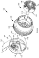
- Figs. 2A and 2B depict front and back perspective views of an outer-rotor brushless DC (BLDC) motor 100 with flywheel 102, according to an embodiment.
- flywheel 102 includes three flywheel annular rings 110 that form grooves 112 there between around the outer surface of the flywheel 102.
- flywheel 102 is formed integrally with rotor 120 on an external circumferential surface of the rotor 120 having an increased diameter compared to the remainder of the rotor 120.
- flywheel 102 may be provided as a separate part attached to an outer surface of the rotor 120.
- Flywheel 102 may be made of metal such as steel.
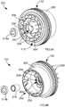
- Figs. 3A and 3B depict front and back exploded views of motor 100, according to an embodiment.
- Fig. 4 depicts a partially cut-off and partially-exploded view of the brushless motor 100, according to an embodiment.
- motor 100 in addition to the outer rotor 120, includes a stator assembly 130 coupled to a shaft 110, and a motor end cap 140.
- stator assembly 130 includes a stator lamination stack 132 having a plurality of stator teeth with slots formed therebetween. Stator windings 134 are wound around the stator teeth defining the phases of the motor 100. In an embodiment, where motor 100 is a three-phase BLDC motor, three windings 134 defining the three phases of the motor 100 are disposed around the stator lamination stack 132, each winding 134 being wound on opposite two teeth across one another. In an embodiment, stator assembly 130 further includes two end insulators 136 attached to the end surfaces of the stator lamination stack 132. In an embodiment, the stator lamination stack 132 is mounted (e.g., via press-fitting) on a shaft 110.
- motor end cap 140 is disposed at an end of the motor 100 and also mounted (e.g., via press-fitting) on the shaft 110 opposite the stator assembly 130.
- Motor end cap 140 includes a back plate 142 disposed adjacent a fan 122 of the rotor 120 (discussed below) that acts as a baffle for the fan 122.
- End cap 140 also includes a circumferential portion 144 with air conduits 146 to redirect the air flow from the fan 122 towards other parts of the tool 10, for example, the control unit 70 (see Fig. 1 ).
- End cap 140 includes a through-hole 148 sized to securely receive the shaft 110.
- end cap 140 further includes a rotational position sensor board 150 therein.
- Positional sensor board 150 may include, for example, three Hall sensors 152 facing the rotor 120 and a connector 154 projecting outside the back plate 142 to be accessible from outside the motor 100.
- the outer-rotor 120 is described herein, according to an embodiment of the invention.
- Use of a flywheel on an outer-rotor of a brushless motor is known.
- An example of such an assembly is described in US Patent No. 8,047,415 , which is incorporated herein by reference in its entirety.
- the present embodiment describes an improved outer-rotor for a brushless motor, wherein in an embodiment, the rotor components, including the rotor fan, bearing pocket, etc. are formed within the rotor using a simple mold in an efficient, compact, and easy to manufacture process, as described in detail below.
- Fig. 5 depicts a cut-off perspective view of the outer-rotor assembly 120, according to a first embodiment of the invention.
- outer-rotor assembly 120 includes a substantially-cylindrical metallic rotor body 202 on which the flywheel 102, including annular rings 110, is integrally formed.
- Rotor body 202 and flywheel 102 may be formed of any metallic material such as steel.
- Rotor magnets 210 are secured to an inner surface of the rotor body 202.
- a fan/rotor molded structure 220 is molded inside the rotor body 202 to form and/or support various rotor assembly 120 components, as discussed herein.
- fan/rotor molded structure 220 is formed from epoxy, resin, plastic, or any other moldable non-conductive material.
- the fan/rotor molded structure 220 includes a main body 222 formed primarily inside an inner surface of the rotor body 202.
- the fan/rotor molded structure 220 further includes a plurality of radial members 204 projecting inwardly from the main body 222 towards a center of the rotor 120.
- the fan/rotor molded structure 220 forms a bearing support member 224 that supports one or more shaft ball bearings 214a, 214b.
- the radial members 204 may be disposed at angularly (i.e., substantially diagonally) so as to form blades of a radial fan that generates airflow with the rotation of the rotor 120.
- Bearing support member 224 may be cylindrical and elongated, sized to press-fittingly receive the bearings 214a and 214b.
- the bearing support member 224 is disposed along a center portion of the rotor 120 near the stator assembly 130. As such both bearings 214a and 214b are secured to the rotor assembly 120 on one side of the stator assembly 130. This arrangement substantially eases the assembly process.
- the fan/rotor molded structure 220 is additionally formed with a plurality of blades 228 axially extending from the distal end 226 of the main body 222 to form the axial fan 122 proximate the end cap 140.
- main body 202 of the fan/rotor molded structure 220 extends to an axial end 232 of the rotor main body 202 opposite the fan 122 to cover the rotor permanent magnets 210 on the inner surface of the rotor main body 202.
- bearing support member 224 of the fan/rotor molded structure 220 additionally includes a sense magnet mount 230 for sense magnet ring 212 in the vicinity of the fan 122.
- fan/rotor molded structure 220 herein may be obtained using any molding mechanisms such as over-molding, insert-molding or injection-molding.
- Fig. 6 depicts a perspective view of the substantially-cylindrical rotor body 202 including the flywheel 102, without the fan/rotor molded structure 220, according to an embodiment.
- the flywheel 102 includes two or more annular rings 110 on the outer surface of the rotor body 202 near one end, forming one or more annular grooves 112 therebetween.
- Fig. 7 depicts the rotor body 202 including the flywheel 102, with rotor magnets 210 mounted therein, according to an embodiment.
- four permanent magnets (e.g., ferrite or rare earth magnets) 210 are securely placed inside an inner surface of the rotor body 202.
- the inner surface of the rotor body 202 may include a mounting portion 240 that is recessed from the rest of its inner surface 242 where the flywheel 102 is located, such that the surface of the magnet 210 is substantially on the same cylindrical plane as the surface 242.
- the magnets 210 will magnetically attach to the rotor body 202, though alternatively or additionally an adhesive may be used to secure the magnets 210 to the rotor body 202.
- the magnets 210 are mounted on a distal end of the rotor body 202 opposite the flywheel 102.
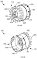
- Figs. 8A and 8B depict front and back perspective views of rotor assembly 120 including the flywheel 110 and rotor body 202, with the fan/rotor molded structure 220 molded therein, according to an embodiment.
- the flywheel 110 and rotor body 202 including the magnets 210, are placed in a mold machine and the fan/rotor molded structure 220 is molded in the area inside the flywheel 110 and rotor body 202 in one molding step.
- the molding forms the radial fan blades 204, the axial fan 112, the bearing support member 224, and the sense magnet mount 230, all integrally as a part of a single molded structure.
- Figs. 9A and 9B depict front and back perspective views of the fan/rotor molded structure 220 without the flywheel 110 and rotor body 202, according to an embodiment.
- a magnet retention portion 252 extending from a main body 222 of the fan/rotor molded structure 220 is a magnet retention portion 252 with magnet pockets 250 around the rotor magnets 210 when the molding process is completed.
- the rotor magnets 210 are completely covered with a layer of the molding of the magnet retention portion 252 disposed between the rotor magnets 210 and the stator assembly 130. It must be understood that alternative embodiments where the molding only partially covers the magnets 210 is within the scope of this disclosure.
- the fan/rotor molded structure 220 additionally includes radial fan blades 204 and bearing support member 224, including sense magnet mount 230 with retention features 274 for mounting and supporting sense magnet ring 212, as described above.
- the fan/rotor molded structure 220 additionally includes blades 228 axially extending from the distal end 226 of the main body 222 to form the axial fan 122 proximate the end cap 140, as described above.
- a spacer (or bushing) 216 is inserted into bearing support member 224, and rotor bearings 214a and 214b are press-fitted into the bearing support member 224 at the two ends of the spacer 216.
- first bearing 214a is press-fittingly inserted axially into the bearing support member 224.
- the bearing support member 224 includes a first lip 260 (see Fig. 5 ) on its inner surface against which the first bearing 214a sits when fully inserted. Then, bearing spacer 216 is inserted into the opening of the bearing support member 224 opposite the first bearing 214a.
- the second bearing 214b is press-fittingly inserted into the bearing support member 224 until in comes in contact with a second lip 262 (see Fig. 5 ).
- the bearings 214a, 214b may be secured inside the support structure via an adhesive.
- a distal end 264 of the bearing support member 224 where the second bearing 214b is located may slightly protrude from the end of the second bearing 214b. This portion of the bearing support member 224 may be crimped by, for example, heat-staking to axially retain the second bearing 214b within the bearing support member 224.
- the first bearing 214a may be axially retained via the sense magnet ring 212, as discussed below.
- the bearing support member 224 is attached to the main body 222 of the fan/rotor molded structure 220 via the radial fan blades 204. In an embodiment, the bearing support structure is radially aligned with the flywheel 102.
- the rotor assembly 120 is supported on the motor shaft 110 by two bearings 214a, 214b that are both axially arranged on one side of the stator assembly 130. This greatly simplifies the assembly process, as the stator 130 can be assembled into the opening 246 of the rotor assembly 120 after the rotor assembly process is complete. Furthermore, the stator windings 134 become easily accessible on one side of the stator 130 opposite the bearing support member 224. As shown in Fig.
- the three motor wires 72 from the control unit 70 read the stator 130 from one side of the motor 100 and are coupled (via soldering, fusing, etc.) directly to the stator windings 134. This greatly simplifies the routing and connectivity of the motor wires 72. Additionally, both bearings 214a, 214b are supported via a single structure, which saves space and material. Finally, the bearing support member 224 is supported by the radial fan blades 204, which further saves on space and material.
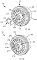
- Figs. 10A and 10B depict perspective views of rotor assembly 120, prior to and after the assembly of sense magnet ring 212, respectively, according to an embodiment.
- the sense magnet ring 212 is a single piece magnet forms in the shape of a ring.
- the ring includes four magnetic poles that are aligned with the four poles of the rotor 120, i.e., with the four rotor magnets 210.
- the ring is positioned at close proximity to rotational position sensor board 150 (e.g. Hall sensor board) to allow the sensors 152 to detect the rotational position of the sense magnet ring 212, and thereby the rotor 120.
- rotational position sensor board 150 e.g. Hall sensor board
- the sense magnet ring 212 includes projecting transition areas 270 aligned with the rotor magnets 210, and recessed areas 272 disposed between the projecting transition areas 270.
- the transition areas between adjacent poles of the sense magnet ring are located at approximately the centers of the projecting transition areas 270. In other words, the ends of the opposite poles meet near the center of the projecting transition areas 270.
- the recessed areas 272 may be recessed radially or axially (or both axially and radially) with respect to the radially-projecting transition areas 270.
- the projecting transition areas 270 may be radially projecting with respect to an outer periphery of the recessed areas 272, or axially projecting with respect to an outer plate of the recessed areas 272. With this arrangement, the transition areas 270 have a higher magnetic flux as sensed by the sensors 152, allowing the sensors 152 to detect the magnetic transition between the poles more efficiently.
- sense magnet mount 230 having alignment and retention features 274 that receive and support the sense magnet ring 212.
- the alignment and retention features 274 include four axial projection formed around the periphery of the axial end of the bearing support structure224.
- the radially-projecting transition areas 270 of the sense magnet ring 212 are received between the axial projections 274 of sense magnet mount 230.
- sense magnet mount 230 may also include a notch or a similar keying feature for proper polar alignment of the sense magnet ring 212 with the sense magnet mount 230. In this manner, the mount and support for the sense magnet ring 212 is provided in the molding of the fan/rotor molded structure 224.
- Fig. 11 depicts an alternative sense magnet ring 212 having transition areas 280 that are raised axially, but not radially, with respect to a plane of the recessed areas 282.
- This arrangement may be preferred where the positional sensors 152 (e.g., Hall sensors) are disposed further from the sense magnet 212 in the axial direction.
- the ring 212 includes through-holes within the recessed areas 282 and the sense magnet mount 230 at the end of the bearing support structure 224 of the fan/rotor molded structure 220 includes corresponding legs 284 arranged to mate with the through-holes of the sense magnet ring 212.
- Figs. 12A and 12B depict front and back perspective views of a motor end cap 140, according to an embodiment.
- the motor end cap 140 includes a through-hole 148 that receives the motor shaft and a back plate 142 (i.e., a baffle) that is arranged in parallel to the axial fan 122 of the motor 100.
- a back plate 142 i.e., a baffle
- At the periphery of the back plate 142 is provided a cylindrical circumferential portion 144 that mates with the end of the flywheel 102.
- the circumferential portion 144 receives the axial fan 122, as well as a portion of the bearing support structure 224 and the sense magnet ring 212 therein.
- the circumferential portion 144 includes two air conduits 146 that allow hot air generated by the fans through the motor to be expelled.
- end cap 140 further includes a rotational position sensor board 150 therein.
- Positional sensor board 150 may include, for example, three Hall sensors 152 facing the rotor 120 and a connector 154 projecting outside the back plate 142 to be accessible from outside the motor 100.
- the back plate 142 includes a slot 155.
- Positional sensor board 150 e.g., Hall sensor PCB
- the board 150 includes a curved portion shaped to be disposed around the through-hole 148.
- the positional sensor board 150 includes three positional sensors 152 disposed around the through-hole 148. When the motor is fully assembled, the positional sensors 152 are in close proximity to the axially-projecting (or radially-raised) transition areas 270 of the sense-magnet ring 212 for an accurate rotational reading of the rotor 120.
- a back surface of the positional sensor board includes connector 154 (including, e.g., three terminals for the three sensors) that is exposed through the slot 155. This arrangement allows the connection port to be accessible from outside the motor without having to route wires directly to the Hall sensors.
Landscapes
- Engineering & Computer Science (AREA)
- Power Engineering (AREA)
- Microelectronics & Electronic Packaging (AREA)
- Mechanical Engineering (AREA)
- Connection Of Motors, Electrical Generators, Mechanical Devices, And The Like (AREA)
- Inverter Devices (AREA)
- Permanent Field Magnets Of Synchronous Machinery (AREA)
Abstract
Description
- This disclosure claims the benefit of
U.S. Provisional Application No. 62/093,803 filed December 18, 2014 U.S. Provisional Application No. 62/093,785 filed December 18, 2014 - This disclosure relates to power tools. More particularly, the present invention relates to brushless motor assembly for a fastening power tool.
- Finish Nailers are fastening tools used in construction for crown molding, cabinet molding, door installation, exterior trim and variety of other finish operations. Finish nailers are may be gas powered, pneumatic or electro-magnetic depending on the source of energy for operation of nail firing mechanism. An electro-magnetically powered nailer uses a motor as a prime mover that drives a flywheel. In battery-powered applications, the motor may be, for example, a brushed DC motor or a brushless DC motor. The nailer battery may include, for example, Li-Ion / Ni-Cd battery cells. Flywheel runs at a pre-defined speed, thus storing energy in the form of kinetic energy. This kinetic energy is then transferred to the mechanical linkage that drives the nails.
- Finish nailer need a lot less energy as compared to other nailing applications such as framing, fencing or concrete. The nail sizes are typically 15Ga to 18Ga in diameter. The main user critical-to-quality requirement for a finish nailer is small size and light weight. What is therefore needed is to provide a motor design that is compact yet capable of outputting sufficient power to drive the fastener.
- According to an embodiment of the invention, an electric brushless DC (BLDC) motor is provided, comprising: an outer rotor assembly having a substantially-cylindrical metallic rotor body having, rotor magnets mounted within an inner surface of the rotor body, and a molded structure formed within the rotor body. In an embodiment, the molded structure includes a main body formed on an inner surface of the rotor body to securely cover and retain the rotor magnets on the inner surface of the rotor body, an axial fan formed at an end of the rotor body opposite the rotor magnets, and a sense magnet mount formed at approximately a radial center portion of the axial fan. In an embodiment, the motor further includes a stator assembly received inside the outer rotor assembly and mounted on a shaft; and a sense magnet ring mounted on the sense magnet mount.
- In an embodiment, the molded structure includes at least one of a proxy, plastic, or resin material.
- In an embodiment, the outer rotor assembly further includes a flywheel integrally formed on an outer surface of the rotor body.
- In an embodiment, the molded structure integrally includes at least one radial member projecting inwardly from the main body towards a center of the outer rotor assembly between the axial fan and the rotor magnets; and a bearing support member having a substantially cylindrical shape in an axial direction of the outer rotor and supported by the at least one radial member.
- In an embodiment, the radial member includes radial fan blades angularly disposed to generate an airflow with the rotation of the outer rotor.
- In an embodiment, the bearing support member is configured to securely receive two bearings affixed to the shaft therein.
- According to an embodiment, a power tool is provided including a housing and an electric brushless DC (BLDC) motor according to the above description disposed within the housing.
- According to another embodiment of the invention, an electric brushless DC (BLDC) motor is provided including an outer rotor assembly having a substantially-cylindrical metallic rotor body having, rotor magnets mounted within an inner surface of the rotor body, and a molded structure formed within the rotor body. In an embodiment, the molded structure integrally includes a main body formed on an inner surface of the rotor body, at least one radial member projecting inwardly from the main body towards a center of the outer rotor assembly between the axial fan and the rotor magnets, and a bearing support member having a substantially cylindrical shape in an axial direction of the outer rotor and supported by the at least one radial member. In an embodiment, the motor further includes a stator assembly received inside the outer rotor assembly and mounted on a shaft, the shaft being received inside the bearing support member and affixed rotatably therein via two bearings affixed to the shaft therein.
- In an embodiment, the molded structure comprises at least one of a proxy, plastic, or resin material.
- In an embodiment, the outer rotor assembly further includes a flywheel integrally formed on an outer surface of the rotor body.
- In an embodiment, the molded structure integrally includes a magnet retention portion covering and retaining the rotor magnets on the inner surface of the rotor body.
- In an embodiment, the molded structure integrally includes an axial fan formed at an end of the rotor body opposite the rotor magnets.
- In an embodiment, the molded structure integrally includes a sense magnet mount formed at an end of the bearing support member opposite the stator assembly, the electric motor further comprising a sense magnet ring mounted on the sense magnet mount.
- In an embodiment, the at least one radial member includes a radial fan blades angularly disposed to generate an airflow with the rotation of the outer rotor.
- According to an embodiment, a power tool is provided including a housing and an electric brushless DC (BLDC) motor as described above disposed within the housing.
- The drawings described herein are for illustration purposes only and are not intended to limit the scope of this disclosure in any way.
-
Fig. 1 depicts a side view of a fastening tool with a housing half removed, according to an embodiment; -
Figs. 2A and 2B depict front and back perspective views of an overmolded outer-rotor brushless motor with an integrated flywheel, according to an embodiment; -
Figs. 3A and3B depict front and back exploded views of the outer-rotor brushless motor, according to an embodiment; -
Fig. 4 depicts a partially cut-off exploded view of the outer-rotor brushless motor, according to an embodiment; -
Fig. 5 depicts a partially cut-off perspective view of the outer-rotor assembly of the brushless motor, according to an embodiment; -
Fig. 6 depicts a perspective view of the outer-rotor main body and flywheel, according to an embodiment; -
Fig. 7 depicts a perspective view of the outer-rotor main body with rotor magnets assembled therein, according to an embodiment; -
Figs. 8A and 8B depict front and back views of the outer-rotor main body with the fan/rotor molded structure molded therein, according to an embodiment; -
Figs. 9A and 9B depict front and back views of the fan/rotor molded structure alone without the rotor main body, according to an embodiment; -
Figs. 10A and 10B depict perspective views of the outer-rotor assembly with a sense magnet ring prior to and after assembly onto the fan/rotor molded structure, according to an embodiment; -
Fig. 11 depicts a perspective view of the outer-rotor having an alternative sense magnet ring assembled into the fan/rotor molded structure, according to an embodiment; and -
Figs. 12A and 12B depict front and back perspective views of a motor end cap, according to an embodiment. - Corresponding reference numerals indicate corresponding parts throughout the several views of the drawings.
-
Fig. 1 depicts a perspective view of a fastening tool 10 (e.g., a nailer) with a housing half removed, according to an embodiment. Thefastening tool 10 shown herein includes an outer-rotorbrushless DC motor 100. The outer rotor of themotor 100 is integrally formed with aflywheel 102. In an embodiment, thefastening tool 10 further includes ahousing 12, aninput unit 20 housed within ahandle 14 of the housing and coupled to anactuator 22 disposed outside thehousing 12, and acontrol unit 70. In an embodiment,control unit 70 includes a micro-controller or other programmable control module and power switching components for controlling a commutation of themotor 100.Control unit 70 is coupled to a power source (not shown), which may be a DC power source (e.g., a removable battery pack) or an AC power source (e.g., a 120V AC).Control unit 70 is also coupled to theinput unit 20 viawires 74 and regulates a supply of power from the power source to themotor 100 based on a logic signal from theinput unit 20.Control unit 70 is coupled to motor terminals via threelead wires 72. - In an embodiment,
fastening tool 10 further includes anosepiece assembly 30 including acontract trip mechanism 32 coupled to thehousing 12, amagazine assembly 40, adriver assembly 50 including adriver 52 and areturn mechanism 52, anactivation assembly 60, and asolenoid 62, among other components. In an embodiment, actuation of theactuator 22 whilecontact trip mechanism 32 is in contact with a workpiece causes thesolenoid 62 to engage theactivation assembly 62.Activation assembly 62 translates forward and engages thedriver 52 to initiate driving engagement between thedriver 52 and theflywheel 102. In an embodiment, theflywheel 102 includes one or more flywheel rings that form one or more grooves around the outer surface of theflywheel 102. Thedriver 52 includes corresponding railings that engage the grooves of the flywheel. Rotation of theflywheel 102 causes thedriver 52 to accelerate axially and drive a fastener into a workpiece. - The present disclosure is focused on the structure and features of the
motor 100. Details of the components and operation of an exemplary fastening tool are beyond the scope of this disclosure and can be found inU.S. Patent No. 6,971,567 andUS. Patent Publication No. 2012/0097729 , both of which are incorporated herein by reference in their entirety. It is further noted that while themotor 100 of this disclosure is described with reference to a fastening tool according to an exemplary embodiment,motor 100 may similarly be used in other power tools and other rotary devices. -
Figs. 2A and 2B depict front and back perspective views of an outer-rotor brushless DC (BLDC) motor 100 withflywheel 102, according to an embodiment. In an embodiment,flywheel 102 includes three flywheelannular rings 110 that formgrooves 112 there between around the outer surface of theflywheel 102. In an embodiment,flywheel 102 is formed integrally withrotor 120 on an external circumferential surface of therotor 120 having an increased diameter compared to the remainder of therotor 120. Alternatively,flywheel 102 may be provided as a separate part attached to an outer surface of therotor 120.Flywheel 102 may be made of metal such as steel. -
Figs. 3A and3B depict front and back exploded views ofmotor 100, according to an embodiment.Fig. 4 depicts a partially cut-off and partially-exploded view of thebrushless motor 100, according to an embodiment. As shown in these figures, in addition to theouter rotor 120,motor 100 includes astator assembly 130 coupled to ashaft 110, and amotor end cap 140. - In an embodiment,
stator assembly 130 includes astator lamination stack 132 having a plurality of stator teeth with slots formed therebetween.Stator windings 134 are wound around the stator teeth defining the phases of themotor 100. In an embodiment, wheremotor 100 is a three-phase BLDC motor, threewindings 134 defining the three phases of themotor 100 are disposed around thestator lamination stack 132, each winding 134 being wound on opposite two teeth across one another. In an embodiment,stator assembly 130 further includes twoend insulators 136 attached to the end surfaces of thestator lamination stack 132. In an embodiment, thestator lamination stack 132 is mounted (e.g., via press-fitting) on ashaft 110. - In an embodiment,
motor end cap 140 is disposed at an end of themotor 100 and also mounted (e.g., via press-fitting) on theshaft 110 opposite thestator assembly 130.Motor end cap 140 includes aback plate 142 disposed adjacent afan 122 of the rotor 120 (discussed below) that acts as a baffle for thefan 122.End cap 140 also includes acircumferential portion 144 withair conduits 146 to redirect the air flow from thefan 122 towards other parts of thetool 10, for example, the control unit 70 (seeFig. 1 ).End cap 140 includes a through-hole 148 sized to securely receive theshaft 110. - In an embodiment,
end cap 140 further includes a rotationalposition sensor board 150 therein.Positional sensor board 150 may include, for example, threeHall sensors 152 facing therotor 120 and aconnector 154 projecting outside theback plate 142 to be accessible from outside themotor 100. - The outer-
rotor 120 is described herein, according to an embodiment of the invention. Use of a flywheel on an outer-rotor of a brushless motor is known. An example of such an assembly is described inUS Patent No. 8,047,415 , which is incorporated herein by reference in its entirety. The present embodiment describes an improved outer-rotor for a brushless motor, wherein in an embodiment, the rotor components, including the rotor fan, bearing pocket, etc. are formed within the rotor using a simple mold in an efficient, compact, and easy to manufacture process, as described in detail below. -
Fig. 5 depicts a cut-off perspective view of the outer-rotor assembly 120, according to a first embodiment of the invention. As shown in this figure, and further with reference toFig. 4 , in an embodiment, outer-rotor assembly 120 includes a substantially-cylindricalmetallic rotor body 202 on which theflywheel 102, includingannular rings 110, is integrally formed.Rotor body 202 andflywheel 102 may be formed of any metallic material such as steel.Rotor magnets 210 are secured to an inner surface of therotor body 202. A fan/rotor moldedstructure 220 is molded inside therotor body 202 to form and/or supportvarious rotor assembly 120 components, as discussed herein. In an embodiment, fan/rotor moldedstructure 220 is formed from epoxy, resin, plastic, or any other moldable non-conductive material. - In an embodiment, the fan/rotor molded
structure 220 includes amain body 222 formed primarily inside an inner surface of therotor body 202. The fan/rotor moldedstructure 220 further includes a plurality ofradial members 204 projecting inwardly from themain body 222 towards a center of therotor 120. At the center of therotor 120, the fan/rotor moldedstructure 220 forms abearing support member 224 that supports one or moreshaft ball bearings radial members 204 may be disposed at angularly (i.e., substantially diagonally) so as to form blades of a radial fan that generates airflow with the rotation of therotor 120.Bearing support member 224 may be cylindrical and elongated, sized to press-fittingly receive thebearings support member 224 is disposed along a center portion of therotor 120 near thestator assembly 130. As such bothbearings rotor assembly 120 on one side of thestator assembly 130. This arrangement substantially eases the assembly process. - In an embodiment, the fan/rotor molded
structure 220 is additionally formed with a plurality ofblades 228 axially extending from thedistal end 226 of themain body 222 to form theaxial fan 122 proximate theend cap 140. In an embodiment,main body 202 of the fan/rotor moldedstructure 220 extends to anaxial end 232 of the rotormain body 202 opposite thefan 122 to cover the rotorpermanent magnets 210 on the inner surface of the rotormain body 202. In an embodiment, bearingsupport member 224 of the fan/rotor moldedstructure 220 additionally includes asense magnet mount 230 forsense magnet ring 212 in the vicinity of thefan 122. These features are described herein in detail. - It is noted that while the fan/rotor molded
structure 220 herein may be obtained using any molding mechanisms such as over-molding, insert-molding or injection-molding. -
Fig. 6 depicts a perspective view of the substantially-cylindrical rotor body 202 including theflywheel 102, without the fan/rotor moldedstructure 220, according to an embodiment. As discussed above, theflywheel 102 includes two or moreannular rings 110 on the outer surface of therotor body 202 near one end, forming one or moreannular grooves 112 therebetween. -
Fig. 7 depicts therotor body 202 including theflywheel 102, withrotor magnets 210 mounted therein, according to an embodiment. In an embodiment, four permanent magnets (e.g., ferrite or rare earth magnets) 210 are securely placed inside an inner surface of therotor body 202. In an embodiment, the inner surface of therotor body 202 may include a mountingportion 240 that is recessed from the rest of itsinner surface 242 where theflywheel 102 is located, such that the surface of themagnet 210 is substantially on the same cylindrical plane as thesurface 242. In an embodiment, themagnets 210 will magnetically attach to therotor body 202, though alternatively or additionally an adhesive may be used to secure themagnets 210 to therotor body 202. In an embodiment, themagnets 210 are mounted on a distal end of therotor body 202 opposite theflywheel 102. -
Figs. 8A and 8B depict front and back perspective views ofrotor assembly 120 including theflywheel 110 androtor body 202, with the fan/rotor moldedstructure 220 molded therein, according to an embodiment. In this step of the assembly process, in an embodiment, theflywheel 110 androtor body 202, including themagnets 210, are placed in a mold machine and the fan/rotor moldedstructure 220 is molded in the area inside theflywheel 110 androtor body 202 in one molding step. The molding forms theradial fan blades 204, theaxial fan 112, the bearingsupport member 224, and thesense magnet mount 230, all integrally as a part of a single molded structure. -
Figs. 9A and 9B depict front and back perspective views of the fan/rotor moldedstructure 220 without theflywheel 110 androtor body 202, according to an embodiment. As shown in these figures, extending from amain body 222 of the fan/rotor moldedstructure 220 is amagnet retention portion 252 withmagnet pockets 250 around therotor magnets 210 when the molding process is completed. In this embodiment, therotor magnets 210 are completely covered with a layer of the molding of themagnet retention portion 252 disposed between therotor magnets 210 and thestator assembly 130. It must be understood that alternative embodiments where the molding only partially covers themagnets 210 is within the scope of this disclosure. - In an embodiment, an inner surface of the
main body 222 and themagnet cover portion 252 of the fan/rotor moldedstructure 220 are substantially formed along a same cylindrical plane. This cylindrical plane forms anopening 256 through which thestator assembly 130 is received within therotor assembly 120. - In an embodiment, the fan/rotor molded
structure 220 additionally includesradial fan blades 204 and bearingsupport member 224, includingsense magnet mount 230 with retention features 274 for mounting and supportingsense magnet ring 212, as described above. In an embodiment, the fan/rotor moldedstructure 220 additionally includesblades 228 axially extending from thedistal end 226 of themain body 222 to form theaxial fan 122 proximate theend cap 140, as described above. - Referring back to
Figs. 8A and 8B , in an embodiment, once the molding process is complete, a spacer (or bushing) 216 is inserted into bearingsupport member 224, androtor bearings bearing support member 224 at the two ends of thespacer 216. In an embodiment,first bearing 214a is press-fittingly inserted axially into thebearing support member 224. Thebearing support member 224 includes a first lip 260 (seeFig. 5 ) on its inner surface against which thefirst bearing 214a sits when fully inserted. Then, bearingspacer 216 is inserted into the opening of thebearing support member 224 opposite thefirst bearing 214a. Finally, thesecond bearing 214b is press-fittingly inserted into thebearing support member 224 until in comes in contact with a second lip 262 (seeFig. 5 ). In an alternative or additional embodiment, thebearings - In an embodiment, a
distal end 264 of thebearing support member 224 where thesecond bearing 214b is located may slightly protrude from the end of thesecond bearing 214b. This portion of thebearing support member 224 may be crimped by, for example, heat-staking to axially retain thesecond bearing 214b within thebearing support member 224. Thefirst bearing 214a may be axially retained via thesense magnet ring 212, as discussed below. - In an embodiment, as described above, the bearing
support member 224 is attached to themain body 222 of the fan/rotor moldedstructure 220 via theradial fan blades 204. In an embodiment, the bearing support structure is radially aligned with theflywheel 102. - The arrangement of two rotor bearings within the
bearing support member 224 of the fan/rotor moldedstructure 220 as described above offers several advantages. First, therotor assembly 120 is supported on themotor shaft 110 by twobearings stator assembly 130. This greatly simplifies the assembly process, as thestator 130 can be assembled into the opening 246 of therotor assembly 120 after the rotor assembly process is complete. Furthermore, thestator windings 134 become easily accessible on one side of thestator 130 opposite thebearing support member 224. As shown inFig. 1 , the threemotor wires 72 from thecontrol unit 70 read thestator 130 from one side of themotor 100 and are coupled (via soldering, fusing, etc.) directly to thestator windings 134. This greatly simplifies the routing and connectivity of themotor wires 72. Additionally, bothbearings support member 224 is supported by theradial fan blades 204, which further saves on space and material. -
Figs. 10A and 10B depict perspective views ofrotor assembly 120, prior to and after the assembly ofsense magnet ring 212, respectively, according to an embodiment. In an embodiment, thesense magnet ring 212 is a single piece magnet forms in the shape of a ring. The ring includes four magnetic poles that are aligned with the four poles of therotor 120, i.e., with the fourrotor magnets 210. The ring is positioned at close proximity to rotational position sensor board 150 (e.g. Hall sensor board) to allow thesensors 152 to detect the rotational position of thesense magnet ring 212, and thereby therotor 120. - According to an embodiment of the invention, the
sense magnet ring 212 includes projectingtransition areas 270 aligned with therotor magnets 210, and recessedareas 272 disposed between the projectingtransition areas 270. In an embodiment, the transition areas between adjacent poles of the sense magnet ring are located at approximately the centers of the projectingtransition areas 270. In other words, the ends of the opposite poles meet near the center of the projectingtransition areas 270. The recessedareas 272 may be recessed radially or axially (or both axially and radially) with respect to the radially-projectingtransition areas 270. In other words, the projectingtransition areas 270 may be radially projecting with respect to an outer periphery of the recessedareas 272, or axially projecting with respect to an outer plate of the recessedareas 272. With this arrangement, thetransition areas 270 have a higher magnetic flux as sensed by thesensors 152, allowing thesensors 152 to detect the magnetic transition between the poles more efficiently. - In an embodiment, and end of the bearing
support structure 224 of the fan/rotor moldedstructure 220 includessense magnet mount 230 having alignment and retention features 274 that receive and support thesense magnet ring 212. The alignment and retention features 274 include four axial projection formed around the periphery of the axial end of the bearing support structure224. In an embodiment, the radially-projectingtransition areas 270 of thesense magnet ring 212 are received between theaxial projections 274 ofsense magnet mount 230. In an embodiment,sense magnet mount 230 may also include a notch or a similar keying feature for proper polar alignment of thesense magnet ring 212 with thesense magnet mount 230. In this manner, the mount and support for thesense magnet ring 212 is provided in the molding of the fan/rotor moldedstructure 224. -
Fig. 11 depicts an alternativesense magnet ring 212 havingtransition areas 280 that are raised axially, but not radially, with respect to a plane of the recessed areas 282. This arrangement may be preferred where the positional sensors 152 (e.g., Hall sensors) are disposed further from thesense magnet 212 in the axial direction. In an embodiment, thering 212 includes through-holes within the recessed areas 282 and thesense magnet mount 230 at the end of the bearingsupport structure 224 of the fan/rotor moldedstructure 220 includes correspondinglegs 284 arranged to mate with the through-holes of thesense magnet ring 212. -
Figs. 12A and 12B depict front and back perspective views of amotor end cap 140, according to an embodiment. In this embodiment, themotor end cap 140 includes a through-hole 148 that receives the motor shaft and a back plate 142 (i.e., a baffle) that is arranged in parallel to theaxial fan 122 of themotor 100. At the periphery of theback plate 142 is provided a cylindricalcircumferential portion 144 that mates with the end of theflywheel 102. Thecircumferential portion 144 receives theaxial fan 122, as well as a portion of the bearingsupport structure 224 and thesense magnet ring 212 therein. Thecircumferential portion 144 includes twoair conduits 146 that allow hot air generated by the fans through the motor to be expelled. - In an embodiment,
end cap 140 further includes a rotationalposition sensor board 150 therein.Positional sensor board 150 may include, for example, threeHall sensors 152 facing therotor 120 and aconnector 154 projecting outside theback plate 142 to be accessible from outside themotor 100. - In an embodiment, the
back plate 142 includes aslot 155. Positional sensor board 150 (e.g., Hall sensor PCB) is mounted on the inside of theback plate 142. In an embodiment, theboard 150 includes a curved portion shaped to be disposed around the through-hole 148. Thepositional sensor board 150 includes threepositional sensors 152 disposed around the through-hole 148. When the motor is fully assembled, thepositional sensors 152 are in close proximity to the axially-projecting (or radially-raised)transition areas 270 of the sense-magnet ring 212 for an accurate rotational reading of therotor 120. In an embodiment, a back surface of the positional sensor board includes connector 154 (including, e.g., three terminals for the three sensors) that is exposed through theslot 155. This arrangement allows the connection port to be accessible from outside the motor without having to route wires directly to the Hall sensors. - The foregoing description of the embodiments has been provided for purposes of illustration and description. It is not intended to be exhaustive or to limit the disclosure. Individual elements or features of a particular embodiment are generally not limited to that particular embodiment, but, where applicable, are interchangeable and can be used in a selected embodiment, even if not specifically shown or described. The same may also be varied in many ways. Such variations are not to be regarded as a departure from the disclosure, and all such modifications are intended to be included within the scope of the disclosure.
Claims (15)
- An electric brushless DC (BLDC) motor comprising:an outer rotor assembly having a substantially-cylindrical metallic rotor body having, a plurality of rotor magnets mounted within an inner surface of the rotor body, and a molded structure formed within the rotor body, the molded structure comprising a main body formed on an inner surface of the rotor body to securely cover and retain the rotor magnets on the inner surface of the rotor body, an axial fan formed at an end of the rotor body opposite the rotor magnets, and a sense magnet mount formed at approximately a radial center portion of the axial fan;a stator assembly received inside the outer rotor assembly and mounted on a shaft; anda sense magnet ring mounted on the sense magnet mount.
- The electric motor of claim 1, wherein the molded structure comprises at least one of a proxy, plastic, or resin material.
- The electric motor of claim 1, the outer rotor assembly further comprising a flywheel integrally formed on an outer surface of the rotor body.
- The electric motor of claim 1, wherein the molded structure integrally comprises:at least one radial member projecting inwardly from the main body towards a center of the outer rotor assembly between the axial fan and the rotor magnets;and a bearing support member having a substantially cylindrical shape in an axial direction of the outer rotor and supported by the at least one radial member.
- The electric motor of claim 4, wherein the at least one radial member comprises a plurality of radial fan blades angularly disposed to generate an airflow with the rotation of the outer rotor.
- The electric motor of claim 4, wherein the bearing support member is configured to securely receive two bearings affixed to the shaft therein.
- The electric motor of claim 1, wherein the stator assembly comprises a plurality of stator teeth and a plurality of stator windings formed around the stator teeth, the stator windings being accessible for connection of a plurality of lead wires from an open end of the outer rotor assembly opposite the sense magnet mount.
- A power tool comprising a housing and an electric brushless DC (BLDC) motor according to claim 1 disposed within the housing.
- An electric brushless DC (BLDC) motor comprising:an outer rotor assembly having a substantially-cylindrical metallic rotor body having, a plurality of rotor magnets mounted within an inner surface of the rotor body, and a molded structure formed within the rotor body, the molded structure integrally comprising a main body formed on an inner surface of the rotor body, at least one radial member projecting inwardly from the main body towards a center of the outer rotor assembly between the axial fan and the rotor magnets, and a bearing support member having a substantially cylindrical shape in an axial direction of the outer rotor and supported by the at least one radial member; anda stator assembly received inside the outer rotor assembly and mounted on a shaft, the shaft being received inside the bearing support member and affixed rotatably therein via two bearings affixed to the shaft therein.
- The electric motor of claim 9, the outer rotor assembly further comprising a flywheel integrally formed on an outer surface of the rotor body.
- The electric motor of claim 9, wherein the molded structure integrally comprises a magnet retention portion covering and retaining the rotor magnets on the inner surface of the rotor body, and an axial fan formed at an end of the rotor body opposite the rotor magnets.
- The electric motor of claim 9, wherein the molded structure integrally comprises a sense magnet mount formed at an end of the bearing support member opposite the stator assembly, the electric motor further comprising a sense magnet ring mounted on the sense magnet mount.
- The electric motor of claim 9, wherein the at least one radial member comprises a plurality of radial fan blades angularly disposed to generate an airflow with the rotation of the outer rotor.
- The electric motor of claim 9, wherein the stator assembly comprises a plurality of stator teeth and a plurality of stator windings formed around the stator teeth, the stator windings being accessible for connection of a plurality of lead wires from an open end of the outer rotor assembly opposite the bearing support member.
- A power tool comprising a housing and an electric brushless DC (BLDC) motor according to claim 9 disposed within the housing.
Applications Claiming Priority (2)
| Application Number | Priority Date | Filing Date | Title |
|---|---|---|---|
| US201462093803P | 2014-12-18 | 2014-12-18 | |
| US201462093785P | 2014-12-18 | 2014-12-18 |
Publications (2)
| Publication Number | Publication Date |
|---|---|
| EP3035508A2 true EP3035508A2 (en) | 2016-06-22 |
| EP3035508A3 EP3035508A3 (en) | 2016-08-03 |
Family
ID=55023945
Family Applications (2)
| Application Number | Title | Priority Date | Filing Date |
|---|---|---|---|
| EP15201249.8A Withdrawn EP3035516A3 (en) | 2014-12-18 | 2015-12-18 | Packaging of a control module for a brushless motor |
| EP15201262.1A Withdrawn EP3035508A3 (en) | 2014-12-18 | 2015-12-18 | Brushless motor assembly for a fastening tool |
Family Applications Before (1)
| Application Number | Title | Priority Date | Filing Date |
|---|---|---|---|
| EP15201249.8A Withdrawn EP3035516A3 (en) | 2014-12-18 | 2015-12-18 | Packaging of a control module for a brushless motor |
Country Status (2)
| Country | Link |
|---|---|
| US (7) | US10193417B2 (en) |
| EP (2) | EP3035516A3 (en) |
Cited By (8)
| Publication number | Priority date | Publication date | Assignee | Title |
|---|---|---|---|---|
| IT201600118253A1 (en) * | 2016-11-23 | 2018-05-23 | Nicotra Gebhardt S P A | External rotor electric motor |
| EP3434420A1 (en) * | 2017-07-24 | 2019-01-30 | Ingersoll-Rand Company | Outrunner motor in cordless power tool |
| WO2020173618A1 (en) * | 2019-02-25 | 2020-09-03 | Robert Bosch Gmbh | Brushless direct current motor of a hand-held power tool |
| US11437900B2 (en) | 2019-12-19 | 2022-09-06 | Black & Decker Inc. | Modular outer-rotor brushless motor for a power tool |
| US11509193B2 (en) | 2019-12-19 | 2022-11-22 | Black & Decker Inc. | Power tool with compact motor assembly |
| US11705778B2 (en) | 2019-12-19 | 2023-07-18 | Black & Decker Inc. | Power tool with compact motor assembly |
| US11757330B2 (en) | 2019-12-19 | 2023-09-12 | Black & Decker, Inc. | Canned outer-rotor brushless motor for a power tool |
| US12176794B2 (en) | 2021-11-19 | 2024-12-24 | Black & Decker Inc. | Outer-rotor brushless motor for a power tool |
Families Citing this family (41)
| Publication number | Priority date | Publication date | Assignee | Title |
|---|---|---|---|---|
| DE102015118695A1 (en) * | 2015-11-02 | 2017-05-04 | Ebm-Papst Mulfingen Gmbh & Co. Kg | Electric motor with improved cooling |
| US10205365B2 (en) | 2016-03-30 | 2019-02-12 | Milwaukee Electric Tool Corporation | Brushless motor for a power tool |
| GB201610953D0 (en) * | 2016-06-23 | 2016-08-10 | Black & Decker Inc | Motor end cap |
| US9979320B2 (en) * | 2016-08-26 | 2018-05-22 | Deere & Company | Electronic inverter assembly |
| EP3297140A1 (en) * | 2016-09-19 | 2018-03-21 | Black & Decker Inc. | Control and power module for brushless motor |
| US10608501B2 (en) | 2017-05-24 | 2020-03-31 | Black & Decker Inc. | Variable-speed input unit having segmented pads for a power tool |
| US10541588B2 (en) * | 2017-05-24 | 2020-01-21 | Black & Decker Inc. | Electronic power module for a power tool having an integrated heat sink |
| US10840776B2 (en) | 2017-05-27 | 2020-11-17 | Actuator Electric Motors | Self-contained brushless motor and brushless controller |
| WO2019204056A1 (en) * | 2018-04-16 | 2019-10-24 | Milwaukee Electric Tool Corporation | Inertial fan for power tool |
| EP3588525B1 (en) * | 2018-06-28 | 2022-02-16 | Black & Decker Inc. | Electronic switch module with oppositely-arranged power switches and discrete heat sinks |
| CN113366740A (en) | 2018-11-29 | 2021-09-07 | 米沃奇电动工具公司 | Rotor assembly for an electric machine |
| US11973374B2 (en) * | 2019-04-24 | 2024-04-30 | Black & Decker Inc. | Outer rotor brushless motor having an axial fan |
| US11571803B2 (en) * | 2019-05-30 | 2023-02-07 | Milwaukee Electric Tool Corporation | Power tool with combined chip for wireless communications and power tool control |
| TWM605151U (en) * | 2020-01-31 | 2020-12-11 | 鑽全實業股份有限公司 | Flywheel-drive electric nailing gun and heat dissipation device thereof |
| US11745323B2 (en) | 2020-11-25 | 2023-09-05 | Black & Decker Inc. | Power tool |
| EP4037158B1 (en) | 2021-02-02 | 2025-07-30 | Black & Decker, Inc. | Brushless motor including a nested bearing bridge |
| WO2022197655A1 (en) * | 2021-03-15 | 2022-09-22 | Milwaukee Electric Tool Corporation | Potting boat heat sink |
| EP4323152A4 (en) * | 2021-04-14 | 2025-01-08 | Black & Decker, Inc. | Fastening tool having home position sensing system |
| US12507623B2 (en) | 2021-05-05 | 2025-12-30 | Black & Decker Inc. | Outer rotor brushless motor and planetary gear assembly for power tool |
| JP7716245B2 (en) | 2021-06-29 | 2025-07-31 | 株式会社マキタ | electric work equipment |
| JP2023005814A (en) | 2021-06-29 | 2023-01-18 | 株式会社マキタ | electric work machine |
| JP2023006092A (en) | 2021-06-30 | 2023-01-18 | 株式会社マキタ | electric work machine |
| CN216981644U (en) * | 2021-08-25 | 2022-07-15 | 米沃奇电动工具公司 | Electric motor and electric tool including the same |
| US20230188004A1 (en) | 2021-12-10 | 2023-06-15 | Black & Decker Inc. | Power tool with compact outer-rotor motor assembly |
| WO2023108051A1 (en) * | 2021-12-10 | 2023-06-15 | Milwaukee Electric Tool Corporation | Inverter including wide-bandgap semiconductor devices in a power tool |
| US20230212882A1 (en) * | 2022-01-04 | 2023-07-06 | Passivebolt, Inc. | Electronic door system, door lock, and lock actuator |
| CN223729618U (en) * | 2022-03-11 | 2025-12-26 | 米沃奇电动工具公司 | Electric motor |
| US12558766B2 (en) * | 2022-08-02 | 2026-02-24 | Milwaukee Electric Tool Corporation | Percussion tool |
| US20240072586A1 (en) * | 2022-08-23 | 2024-02-29 | Black & Decker Inc. | Sealed electric motor |
| US20240223042A1 (en) | 2022-12-30 | 2024-07-04 | Black & Decker Inc. | Compact outer-rotor brushless motor for a power tool |
| WO2024249630A1 (en) | 2023-06-01 | 2024-12-05 | Black & Decker, Inc. | Fastener device with variable feed cycle timing |
| US20250088072A1 (en) | 2023-09-12 | 2025-03-13 | Black & Decker Inc. | Motor bearing shield |
| WO2025059311A1 (en) | 2023-09-12 | 2025-03-20 | Black & Decker, Inc. | Fastener tool with continuously powered flywheel |
| WO2025059392A1 (en) | 2023-09-13 | 2025-03-20 | Black & Decker, Inc. | Fastener device with overmolded nose assembly |
| EP4541513A1 (en) | 2023-09-13 | 2025-04-23 | Black & Decker, Inc. | Fastener device with a sensor for workpiece detection |
| US12558765B2 (en) | 2023-10-04 | 2026-02-24 | Black & Decker Inc. | Fastener tool with drive speed adjustment |
| WO2025122486A1 (en) | 2023-12-04 | 2025-06-12 | Black & Decker, Inc. | Fastener tool with linear motor |
| US20250192624A1 (en) | 2023-12-08 | 2025-06-12 | Black & Decker Inc. | Brushless motor in power tool |
| US20260019018A1 (en) | 2024-07-09 | 2026-01-15 | Black & Decker Inc. | Variable current clip control in power tool |
| US20260025090A1 (en) | 2024-07-17 | 2026-01-22 | Black & Decker Inc. | Motor drive control scheme for reducing negative currents |
| US20260088684A1 (en) | 2024-09-20 | 2026-03-26 | Black & Decker Inc. | Control Module for High-Power Electric Motor |
Citations (4)
| Publication number | Priority date | Publication date | Assignee | Title |
|---|---|---|---|---|
| US6971567B1 (en) | 2004-10-29 | 2005-12-06 | Black & Decker Inc. | Electronic control of a cordless fastening tool |
| EP2127819A1 (en) * | 2008-05-30 | 2009-12-02 | Black & Decker, Inc. | Fastener Driving Tool |
| US8047415B2 (en) | 2008-05-30 | 2011-11-01 | Black & Decker Inc. | Flywheel driven fastener driving tool having retractable nose assembly |
| US20120097729A1 (en) | 2004-04-02 | 2012-04-26 | Black & Decker Inc. | Power take off for cordless nailer |
Family Cites Families (76)
| Publication number | Priority date | Publication date | Assignee | Title |
|---|---|---|---|---|
| US794663A (en) | 1904-10-10 | 1905-07-11 | Henry W Daly | Ammunition-box. |
| US3968920A (en) | 1975-02-12 | 1976-07-13 | Honeywell Inc. | Capstan and motor assembly |
| CH612736A5 (en) | 1976-04-27 | 1979-08-15 | Papst Motoren Kg | |
| US4107591A (en) | 1977-04-14 | 1978-08-15 | The Singer Company | Hall generator position sensing device |
| US5216557A (en) | 1981-09-07 | 1993-06-01 | Papst-Motoren Gmbh & Co. Kg | Disk storage device having a brushless dc drive motor |
| US4658312A (en) | 1981-09-07 | 1987-04-14 | Papst-Motoren Gmbh & Co. K.G. | Disk storage drive |
| USRE35792E (en) | 1981-09-07 | 1998-05-12 | Papst Licensing, Gmbh | Disk storage drive |
| DK463183D0 (en) | 1983-10-07 | 1983-10-07 | Nordisk Ventilator | SHOOT WITH SHAFT LOAD FOR AN AXIAL BLOWER WHEEL |
| US4647806A (en) | 1985-06-10 | 1987-03-03 | Giovanni Giuffrida | Brushless alternator |
| JPS62293959A (en) | 1986-06-11 | 1987-12-21 | Tamagawa Seiki Co Ltd | Brushless dc motor |
| US5015901A (en) * | 1990-03-12 | 1991-05-14 | R. E. Phelon Company, Inc. | Rotor of a magnetmotive device |
| US5895207A (en) | 1993-06-17 | 1999-04-20 | Itt Automotive Europe, Gmbh | Electric motor-pump assembly |
| JP3312370B2 (en) | 1995-03-28 | 2002-08-05 | ミネベア株式会社 | Motor structure |
| US5844338A (en) | 1995-12-18 | 1998-12-01 | Siemens Electric Limited | Slim-line brushless motor with inside mounted single bearing |
| WO1998027638A1 (en) | 1996-12-16 | 1998-06-25 | Globe Motors | Multi-pole ring magnet for rotating electrical machines |
| JPH10304605A (en) * | 1997-04-24 | 1998-11-13 | Toshiba Corp | DC motor |
| JP3396753B2 (en) | 1997-06-20 | 2003-04-14 | ミネベア株式会社 | Bearing structure of brushless DC motor |
| US6501616B1 (en) | 1999-07-29 | 2002-12-31 | Encap Motor Corporation | Hard disc drive with base incorporating a spindle motor stator |
| US6300695B1 (en) | 1999-07-29 | 2001-10-09 | Encap Motor Corporation | High speed spindle motor with hydrodynamic bearings |
| GB2357905B (en) * | 1999-12-01 | 2004-02-11 | Hi Key Ltd | A radio receiver |
| KR100362808B1 (en) | 2000-04-21 | 2002-11-27 | 삼성광주전자 주식회사 | Resin molded brushless direct current motor and method of manufacturing the same |
| DE10212721A1 (en) | 2001-03-24 | 2002-09-26 | Marquardt Gmbh | Control device for brushless DC motor in battery-operated electric handtool has power semiconductors mounted directly or indirectly on control circuit printed circuit board |
| DE10119404A1 (en) | 2001-04-20 | 2002-10-24 | Bosch Gmbh Robert | Electronically commutated dc motor e.g. for cooling water pump in vehicle, has grid stamping for providing all connections to electronic system |
| GB0130602D0 (en) | 2001-12-21 | 2002-02-06 | Johnson Electric Sa | Brushless D.C. motor |
| DE50211524D1 (en) | 2002-11-16 | 2008-02-21 | Minebea Co Ltd | Miniature motor with permanent magnet rotor |
| JP2004236390A (en) | 2003-01-29 | 2004-08-19 | Tokyo Parts Ind Co Ltd | Small-sized brushless motor |
| US7012346B2 (en) | 2003-03-07 | 2006-03-14 | Resmed Limited | Low profile d.c. brushless motor for an impeller mechanism or the like |
| GB0306238D0 (en) | 2003-03-19 | 2003-04-23 | Echlin Do Brasil Ind E Com Ltd | Method of making a pump |
| TW200521350A (en) | 2003-12-25 | 2005-07-01 | Delta Electronics Inc | Magnetic bearing system |
| JP2005256705A (en) | 2004-03-11 | 2005-09-22 | Nippon Densan Corp | Elongated centrifugal fan |
| KR20050099352A (en) * | 2004-04-09 | 2005-10-13 | 엘지전자 주식회사 | Front suction/discharge type outdoor unit for air conditioner |
| JP2005348522A (en) | 2004-06-03 | 2005-12-15 | Hitachi Ltd | Electric power steering motor and manufacturing method thereof |
| US7262110B2 (en) | 2004-08-23 | 2007-08-28 | Micron Technology, Inc. | Trench isolation structure and method of formation |
| JP4631382B2 (en) | 2004-10-04 | 2011-02-16 | 日本電産株式会社 | Brushless motor |
| JP2006107629A (en) | 2004-10-06 | 2006-04-20 | Tokyo Parts Ind Co Ltd | Spindle motor and disk drive unit |
| JP4718260B2 (en) | 2005-07-08 | 2011-07-06 | 日本電産テクノモータホールディングス株式会社 | Molded motor |
| US7715698B2 (en) | 2005-08-31 | 2010-05-11 | Thor Power Corporation | Control electronics for brushless motors |
| JP2007174746A (en) | 2005-12-19 | 2007-07-05 | Jtekt Corp | Electric circuit board, board device, motor, motor device, electric pump, and method of connecting motor to electric circuit board or board device |
| US8427020B2 (en) | 2006-04-20 | 2013-04-23 | Carefusion 212, Llc | Blower assembly with integral injection molded suspension mount |
| JP4912752B2 (en) | 2006-05-30 | 2012-04-11 | 日本電産テクノモータホールディングス株式会社 | motor |
| CN101213723B (en) | 2006-06-09 | 2011-06-22 | 日本电产株式会社 | Brushless motor and fan unit |
| JP4291846B2 (en) * | 2006-11-24 | 2009-07-08 | アスモ株式会社 | Fan motor |
| JP2008173716A (en) | 2007-01-18 | 2008-07-31 | Max Co Ltd | Electric power tool having brushless motor |
| CN101611528B (en) | 2007-03-16 | 2012-06-13 | 三菱电机株式会社 | Brushless motor device |
| KR100890891B1 (en) | 2007-04-10 | 2009-04-02 | 주식회사 아모텍 | Driving device for washing machine and automatic washing machine using same |
| CN101220883B (en) | 2008-01-29 | 2010-09-08 | 上海科勒电子科技有限公司 | Infrared sensor |
| WO2009110206A1 (en) | 2008-03-04 | 2009-09-11 | 三菱電機株式会社 | Brushless motor device and control device |
| JP2009278751A (en) | 2008-05-14 | 2009-11-26 | Kokusan Denki Co Ltd | Starter generator |
| EP2127817B1 (en) | 2008-05-30 | 2012-09-12 | Black & Decker, Inc. | Fastener Driving Tool |
| US20100074881A1 (en) * | 2008-07-11 | 2010-03-25 | Parion Sciences, Inc. | Multiple nebulizer systems |
| JP5512110B2 (en) * | 2008-09-26 | 2014-06-04 | 株式会社マキタ | Electric tool |
| US8132102B2 (en) | 2008-10-28 | 2012-03-06 | Motorola Mobility, Inc. | Messaging interface systems and methods |
| JP2010130847A (en) | 2008-11-28 | 2010-06-10 | Nidec Sankyo Corp | Electric motor |
| CN102149515B (en) | 2009-01-30 | 2014-08-06 | 日立工机株式会社 | electrical tools |
| JP5152526B2 (en) | 2009-04-24 | 2013-02-27 | 株式会社デンソー | In-vehicle power converter |
| WO2010135361A1 (en) | 2009-05-18 | 2010-11-25 | Aspen Motion Technologies, Inc. D/B/A Pentair Technical Products | Water-resistant electric motor |
| JP5766277B2 (en) | 2010-04-19 | 2015-08-19 | ピールブルグ パンプ テクノロジー ゲゼルシャフト ミット ベシュレンクテル ハフツングPierburg Pump Technology GmbH | Electric refrigerant pump used in automobiles |
| JP5206732B2 (en) | 2010-05-21 | 2013-06-12 | 株式会社デンソー | Inverter device and drive device using the same |
| KR101131743B1 (en) | 2010-06-23 | 2012-04-05 | 주식회사 아모텍 | Direct drive apparatus for drum washing machine |
| JPWO2012011274A1 (en) | 2010-07-21 | 2013-09-09 | パナソニック株式会社 | Brushless motor for washing machine and drum type washing machine provided with the same |
| US8587231B2 (en) | 2010-09-28 | 2013-11-19 | Black & Decker Inc. | Method and system for electronic braking of a motor |
| US20120194112A1 (en) | 2011-01-27 | 2012-08-02 | Electrical Systems Integrator Llc | Electrical Brushless Motor |
| US9490700B2 (en) * | 2011-02-25 | 2016-11-08 | Vasco Data Security, Inc. | Portable handheld strong authentication token having parallel-serial battery switching and voltage regulating circuit |
| JP5826526B2 (en) * | 2011-06-08 | 2015-12-02 | 株式会社マキタ | Electric tool |
| JP2013017337A (en) * | 2011-07-05 | 2013-01-24 | Nippon Densan Corp | Motor and method for manufacturing motor |
| US8817469B2 (en) * | 2011-09-23 | 2014-08-26 | Infinera Corporation | Heat transfer using a durable low-friction interface |
| JP5993602B2 (en) * | 2012-04-23 | 2016-09-14 | ミネベア株式会社 | Blower |
| TWM438651U (en) * | 2012-05-09 | 2012-10-01 | Gemtek Technology Co Ltd | Stacked type heat dissipation module of electronic device |
| EP2674256B1 (en) | 2012-06-15 | 2021-11-10 | Black & Decker Inc. | Brushless motor commutation control in a power tool |
| US8604655B1 (en) | 2012-09-25 | 2013-12-10 | Electro-Mariner Corp. | Multi-phase permanent magnet brushless DC electric motor |
| FR2999479B1 (en) * | 2012-12-19 | 2015-01-30 | Valeo Systemes Thermiques | VENTILATION DEVICE FOR VENTILATION, HEATING AND / OR AIR CONDITIONING INSTALLATION |
| FR3004057B1 (en) * | 2013-03-26 | 2017-02-17 | Valeo Systemes Thermiques | CONTROL MODULE OF AN ELECTRICAL APPARATUS |
| US10043619B2 (en) * | 2014-03-28 | 2018-08-07 | Black & Decker Inc. | Biasing member for a power tool forward/reverse actuator |
| KR20160059313A (en) * | 2014-11-18 | 2016-05-26 | 엘지전자 주식회사 | Fan-motor assembly and refrigerator having the same |
| EP3101788A1 (en) * | 2015-05-08 | 2016-12-07 | Johnson Electric S.A. | Single-phase outer-rotor motor and electric apparatus having the same |
| CN107040057A (en) * | 2016-02-03 | 2017-08-11 | 德昌电机(深圳)有限公司 | Blower fan |
-
2015
- 2015-12-17 US US14/973,090 patent/US10193417B2/en active Active
- 2015-12-17 US US14/973,226 patent/US10693344B2/en active Active
- 2015-12-18 EP EP15201249.8A patent/EP3035516A3/en not_active Withdrawn
- 2015-12-18 EP EP15201262.1A patent/EP3035508A3/en not_active Withdrawn
-
2018
- 2018-10-24 US US16/169,435 patent/US11081933B2/en active Active
-
2020
- 2020-05-11 US US16/871,349 patent/US11418089B2/en active Active
-
2021
- 2021-07-29 US US17/388,812 patent/US12068663B2/en active Active
-
2024
- 2024-07-16 US US18/774,557 patent/US12500479B2/en active Active
-
2025
- 2025-11-19 US US19/394,308 patent/US20260074586A1/en active Pending
Patent Citations (4)
| Publication number | Priority date | Publication date | Assignee | Title |
|---|---|---|---|---|
| US20120097729A1 (en) | 2004-04-02 | 2012-04-26 | Black & Decker Inc. | Power take off for cordless nailer |
| US6971567B1 (en) | 2004-10-29 | 2005-12-06 | Black & Decker Inc. | Electronic control of a cordless fastening tool |
| EP2127819A1 (en) * | 2008-05-30 | 2009-12-02 | Black & Decker, Inc. | Fastener Driving Tool |
| US8047415B2 (en) | 2008-05-30 | 2011-11-01 | Black & Decker Inc. | Flywheel driven fastener driving tool having retractable nose assembly |
Cited By (12)
| Publication number | Priority date | Publication date | Assignee | Title |
|---|---|---|---|---|
| IT201600118253A1 (en) * | 2016-11-23 | 2018-05-23 | Nicotra Gebhardt S P A | External rotor electric motor |
| EP3327902A1 (en) * | 2016-11-23 | 2018-05-30 | Nicotra Gebhardt S.P.A. | External-rotor electric motor |
| EP3434420A1 (en) * | 2017-07-24 | 2019-01-30 | Ingersoll-Rand Company | Outrunner motor in cordless power tool |
| WO2020173618A1 (en) * | 2019-02-25 | 2020-09-03 | Robert Bosch Gmbh | Brushless direct current motor of a hand-held power tool |
| US20220173633A1 (en) * | 2019-02-25 | 2022-06-02 | Robert Bosch Gmbh | Brushless Direct Current Motor of a Hand-Held Power Tool |
| US11894752B2 (en) | 2019-02-25 | 2024-02-06 | Robert Bosch Gmbh | Brushless direct current motor of a hand-held power tool |
| US11437900B2 (en) | 2019-12-19 | 2022-09-06 | Black & Decker Inc. | Modular outer-rotor brushless motor for a power tool |
| US11509193B2 (en) | 2019-12-19 | 2022-11-22 | Black & Decker Inc. | Power tool with compact motor assembly |
| US11705778B2 (en) | 2019-12-19 | 2023-07-18 | Black & Decker Inc. | Power tool with compact motor assembly |
| US11757330B2 (en) | 2019-12-19 | 2023-09-12 | Black & Decker, Inc. | Canned outer-rotor brushless motor for a power tool |
| US12218567B2 (en) | 2019-12-19 | 2025-02-04 | Black & Decker Inc. | Power tool having an outer-rotor brushless motor |
| US12176794B2 (en) | 2021-11-19 | 2024-12-24 | Black & Decker Inc. | Outer-rotor brushless motor for a power tool |
Also Published As
| Publication number | Publication date |
|---|---|
| US12068663B2 (en) | 2024-08-20 |
| US10693344B2 (en) | 2020-06-23 |
| US20160181891A1 (en) | 2016-06-23 |
| US10193417B2 (en) | 2019-01-29 |
| EP3035508A3 (en) | 2016-08-03 |
| EP3035516A3 (en) | 2016-07-27 |
| US20240372438A1 (en) | 2024-11-07 |
| US20200274421A1 (en) | 2020-08-27 |
| EP3035516A2 (en) | 2016-06-22 |
| US12500479B2 (en) | 2025-12-16 |
| US20210359575A1 (en) | 2021-11-18 |
| US20260074586A1 (en) | 2026-03-12 |
| US20190058373A1 (en) | 2019-02-21 |
| US11081933B2 (en) | 2021-08-03 |
| US20160181892A1 (en) | 2016-06-23 |
| US11418089B2 (en) | 2022-08-16 |
Similar Documents
| Publication | Publication Date | Title |
|---|---|---|
| US12500479B2 (en) | Brushless motor having an overmolded rotor | |
| US12551993B2 (en) | Power tool with compact motor assembly | |
| US20220166283A1 (en) | Brushless motor for a power tool | |
| US11509193B2 (en) | Power tool with compact motor assembly | |
| US11705778B2 (en) | Power tool with compact motor assembly | |
| US10587163B2 (en) | Brushless motor for a power tool | |
| US12218567B2 (en) | Power tool having an outer-rotor brushless motor | |
| US11489396B2 (en) | Winding retention insert for a brushless motor | |
| EP3840179B1 (en) | Modular outer-rotor brushless motor for a power tool | |
| JP2020141442A (en) | Brushless motor and electric blower | |
| EP4404445A2 (en) | Compact outer-rotor brushless motor for a power tool | |
| EP4033642B1 (en) | Rotor magnet retainer | |
| US12176794B2 (en) | Outer-rotor brushless motor for a power tool | |
| JP6859074B2 (en) | Electric motor and vacuum cleaner |
Legal Events
| Date | Code | Title | Description |
|---|---|---|---|
| PUAI | Public reference made under article 153(3) epc to a published international application that has entered the european phase |
Free format text: ORIGINAL CODE: 0009012 |
|
| AK | Designated contracting states |
Kind code of ref document: A2 Designated state(s): AL AT BE BG CH CY CZ DE DK EE ES FI FR GB GR HR HU IE IS IT LI LT LU LV MC MK MT NL NO PL PT RO RS SE SI SK SM TR |
|
| AX | Request for extension of the european patent |
Extension state: BA ME |
|
| PUAL | Search report despatched |
Free format text: ORIGINAL CODE: 0009013 |
|
| AK | Designated contracting states |
Kind code of ref document: A3 Designated state(s): AL AT BE BG CH CY CZ DE DK EE ES FI FR GB GR HR HU IE IS IT LI LT LU LV MC MK MT NL NO PL PT RO RS SE SI SK SM TR |
|
| AX | Request for extension of the european patent |
Extension state: BA ME |
|
| RIC1 | Information provided on ipc code assigned before grant |
Ipc: H02M 7/00 20060101ALN20160630BHEP Ipc: H02K 11/33 20160101ALN20160630BHEP Ipc: B25F 5/02 20060101ALI20160630BHEP Ipc: H02K 9/06 20060101ALN20160630BHEP Ipc: H02K 1/28 20060101ALN20160630BHEP Ipc: H02K 29/08 20060101AFI20160630BHEP Ipc: H02K 7/08 20060101ALN20160630BHEP Ipc: H02K 11/215 20160101ALI20160630BHEP Ipc: H02K 1/27 20060101ALI20160630BHEP Ipc: H02K 1/18 20060101ALN20160630BHEP |
|
| 17P | Request for examination filed |
Effective date: 20160819 |
|
| RBV | Designated contracting states (corrected) |
Designated state(s): AL AT BE BG CH CY CZ DE DK EE ES FI FR GB GR HR HU IE IS IT LI LT LU LV MC MK MT NL NO PL PT RO RS SE SI SK SM TR |
|
| STAA | Information on the status of an ep patent application or granted ep patent |
Free format text: STATUS: REQUEST FOR EXAMINATION WAS MADE |
|
| STAA | Information on the status of an ep patent application or granted ep patent |
Free format text: STATUS: EXAMINATION IS IN PROGRESS |
|
| 17Q | First examination report despatched |
Effective date: 20171006 |
|
| STAA | Information on the status of an ep patent application or granted ep patent |
Free format text: STATUS: THE APPLICATION IS DEEMED TO BE WITHDRAWN |
|
| 18D | Application deemed to be withdrawn |
Effective date: 20190612 |