EP3035343A2 - Hydrophobic film coated cable for medical device - Google Patents
Hydrophobic film coated cable for medical device Download PDFInfo
- Publication number
- EP3035343A2 EP3035343A2 EP15160248.9A EP15160248A EP3035343A2 EP 3035343 A2 EP3035343 A2 EP 3035343A2 EP 15160248 A EP15160248 A EP 15160248A EP 3035343 A2 EP3035343 A2 EP 3035343A2
- Authority
- EP
- European Patent Office
- Prior art keywords
- group
- cable
- coating film
- hydrophobic
- functional group
- Prior art date
- Legal status (The legal status is an assumption and is not a legal conclusion. Google has not performed a legal analysis and makes no representation as to the accuracy of the status listed.)
- Granted
Links
Images


Classifications
-
- H—ELECTRICITY
- H01—ELECTRIC ELEMENTS
- H01B—CABLES; CONDUCTORS; INSULATORS; SELECTION OF MATERIALS FOR THEIR CONDUCTIVE, INSULATING OR DIELECTRIC PROPERTIES
- H01B7/00—Insulated conductors or cables characterised by their form
- H01B7/17—Protection against damage caused by external factors, e.g. sheaths or armouring
- H01B7/28—Protection against damage caused by moisture, corrosion, chemical attack or weather
- H01B7/2813—Protection against damage caused by electrical, chemical or water tree deterioration
-
- H—ELECTRICITY
- H01—ELECTRIC ELEMENTS
- H01B—CABLES; CONDUCTORS; INSULATORS; SELECTION OF MATERIALS FOR THEIR CONDUCTIVE, INSULATING OR DIELECTRIC PROPERTIES
- H01B7/00—Insulated conductors or cables characterised by their form
- H01B7/17—Protection against damage caused by external factors, e.g. sheaths or armouring
-
- C—CHEMISTRY; METALLURGY
- C09—DYES; PAINTS; POLISHES; NATURAL RESINS; ADHESIVES; COMPOSITIONS NOT OTHERWISE PROVIDED FOR; APPLICATIONS OF MATERIALS NOT OTHERWISE PROVIDED FOR
- C09D—COATING COMPOSITIONS, e.g. PAINTS, VARNISHES OR LACQUERS; FILLING PASTES; CHEMICAL PAINT OR INK REMOVERS; INKS; CORRECTING FLUIDS; WOODSTAINS; PASTES OR SOLIDS FOR COLOURING OR PRINTING; USE OF MATERIALS THEREFOR
- C09D183/00—Coating compositions based on macromolecular compounds obtained by reactions forming in the main chain of the macromolecule a linkage containing silicon, with or without sulfur, nitrogen, oxygen, or carbon only; Coating compositions based on derivatives of such polymers
-
- C—CHEMISTRY; METALLURGY
- C09—DYES; PAINTS; POLISHES; NATURAL RESINS; ADHESIVES; COMPOSITIONS NOT OTHERWISE PROVIDED FOR; APPLICATIONS OF MATERIALS NOT OTHERWISE PROVIDED FOR
- C09D—COATING COMPOSITIONS, e.g. PAINTS, VARNISHES OR LACQUERS; FILLING PASTES; CHEMICAL PAINT OR INK REMOVERS; INKS; CORRECTING FLUIDS; WOODSTAINS; PASTES OR SOLIDS FOR COLOURING OR PRINTING; USE OF MATERIALS THEREFOR
- C09D183/00—Coating compositions based on macromolecular compounds obtained by reactions forming in the main chain of the macromolecule a linkage containing silicon, with or without sulfur, nitrogen, oxygen, or carbon only; Coating compositions based on derivatives of such polymers
- C09D183/04—Polysiloxanes
- C09D183/08—Polysiloxanes containing silicon bound to organic groups containing atoms other than carbon, hydrogen, and oxygen
-
- H—ELECTRICITY
- H01—ELECTRIC ELEMENTS
- H01B—CABLES; CONDUCTORS; INSULATORS; SELECTION OF MATERIALS FOR THEIR CONDUCTIVE, INSULATING OR DIELECTRIC PROPERTIES
- H01B3/00—Insulators or insulating bodies characterised by the insulating materials; Selection of materials for their insulating or dielectric properties
-
- H—ELECTRICITY
- H01—ELECTRIC ELEMENTS
- H01B—CABLES; CONDUCTORS; INSULATORS; SELECTION OF MATERIALS FOR THEIR CONDUCTIVE, INSULATING OR DIELECTRIC PROPERTIES
- H01B3/00—Insulators or insulating bodies characterised by the insulating materials; Selection of materials for their insulating or dielectric properties
- H01B3/18—Insulators or insulating bodies characterised by the insulating materials; Selection of materials for their insulating or dielectric properties mainly consisting of organic substances
- H01B3/30—Insulators or insulating bodies characterised by the insulating materials; Selection of materials for their insulating or dielectric properties mainly consisting of organic substances plastics; resins; waxes
- H01B3/44—Insulators or insulating bodies characterised by the insulating materials; Selection of materials for their insulating or dielectric properties mainly consisting of organic substances plastics; resins; waxes vinyl resins; acrylic resins
- H01B3/443—Insulators or insulating bodies characterised by the insulating materials; Selection of materials for their insulating or dielectric properties mainly consisting of organic substances plastics; resins; waxes vinyl resins; acrylic resins from vinylhalogenides or other halogenoethylenic compounds
-
- H—ELECTRICITY
- H01—ELECTRIC ELEMENTS
- H01B—CABLES; CONDUCTORS; INSULATORS; SELECTION OF MATERIALS FOR THEIR CONDUCTIVE, INSULATING OR DIELECTRIC PROPERTIES
- H01B7/00—Insulated conductors or cables characterised by their form
- H01B7/17—Protection against damage caused by external factors, e.g. sheaths or armouring
- H01B7/28—Protection against damage caused by moisture, corrosion, chemical attack or weather
-
- C—CHEMISTRY; METALLURGY
- C08—ORGANIC MACROMOLECULAR COMPOUNDS; THEIR PREPARATION OR CHEMICAL WORKING-UP; COMPOSITIONS BASED THEREON
- C08G—MACROMOLECULAR COMPOUNDS OBTAINED OTHERWISE THAN BY REACTIONS ONLY INVOLVING UNSATURATED CARBON-TO-CARBON BONDS
- C08G77/00—Macromolecular compounds obtained by reactions forming a linkage containing silicon with or without sulfur, nitrogen, oxygen or carbon in the main chain of the macromolecule
- C08G77/04—Polysiloxanes
- C08G77/22—Polysiloxanes containing silicon bound to organic groups containing atoms other than carbon, hydrogen and oxygen
- C08G77/26—Polysiloxanes containing silicon bound to organic groups containing atoms other than carbon, hydrogen and oxygen nitrogen-containing groups
Definitions
- Embodiments of the present invention relate to a cable, and more particularly, to a hydrophobic cable having a hydrophobic coating film formed on a surface thereof.
- a cable is composed of a bundle of electrical conductors used to connect two or more devices.
- the cable may be prepared so that the cable includes a conductor configured to transmit electrical signals, and a protective sheath serving as an insulator configured to surround the conductor.
- a packing material may be used to prevent contamination of the exterior of such a cable.
- Such a packing material may serve to protect the exterior of the cable from being contaminated or damaged, the events of which may be caused during shipment of the cable.
- users should use the cable in a state in which a packing material is not separated from the cable so as to prevent the exterior of the cable from being contaminated even after the cable is installed in an installation site.
- a hydrophobic cable including a coating film, which is formed by being coated with a coating solution including at least one selected from the group consisting of a silane compound and a siloxane compound.
- a hydrophobic cable includes a conductive unit arranged in a longitudinal direction of the cable, an insulating sheath coated onto an outer surface of the conductive unit and made of a polyvinyl chloride (PVC) material, and a coating film formed outside the insulating sheath.
- the coating film may be formed by curing a coating solution including at least one monomer selected from the group consisting of a silane compound and a siloxane compound.
- the monomer may have at least one organic functional group and at least one inorganic functional group.
- the organic functional group may include at least one organic functional group selected from the group consisting of an organic alkoxy group and an amino group.
- the inorganic functional group may include a metal alkoxide-based inorganic functional group.
- the monomer may be represented by the following Formula 1: wherein R1 represents at least one selected from the group consisting of a methoxy group and an ethoxy group; R2 represents at least one selected from the group consisting of hydrogen, a methyl group, an ethyl group, and a propyl group; and n is 3.
- the coating film may have a hydrogenated silicon structure.
- the coating film may be coupled to the insulating sheath by means of a condensation reaction.
- condensation reaction may include a condensation reaction between the organic functional group of the monomer and a chloride group of the PVC.
- the hydrophobic cable may include a cable for medical devices.
- a cable is a kind of an electric wire, which is used to connect two or more devices and generally has a circular cross section.
- the cable may be extended to connect the devices, and the length of the cable may be properly determined according to a purpose of use.
- a cable having a predetermined length is presented in the accompanying drawings for the sake of convenience, but the length of the cable is not limited thereto.
- the cable may be applied to various fields within the scope of the present invention so as to connect two or more devices.
- a cable for medical devices will be described by way of example for the sake of convenience of description, but one example of the cable used is not limited thereto.
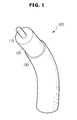
- FIG. 1 is a view illustrating a cable 100 according to one exemplary embodiment of the present invention
- FIG. 2 is a cross-sectional view of the cable 100 according to one exemplary embodiment of the present invention.
- the cable 100 may include a conductive unit 110, an insulating sheath 120, and a coating film 130.
- the conductive unit 110 may be arranged in a longitudinal direction of the cable 100.
- the conductive unit 110 may be provided in the form of a plurality of conductor strands, and the conductor strands may be provided to have different diameters.
- the conductive unit 110 may be made of a conductive material such as cooper, aluminum, etc., but types of the conductive unit 110 are not limited thereto.
- the insulating sheath 120 may be provided to surround the conductive unit 110.
- the insulating sheath 120 may be coated onto an outer portion of the conductive unit 110 to electrically insulate the conductor.
- Cotton, a natural rubber, a synthetic rubber, a plastic, vinyl, and the like may be used as the insulating sheath 120.
- the material of the insulating sheath 120 may be altered according to an applicable scope of the cable 100.
- the main body of an ultrasonic imaging device, and the insulating sheath 120 of the cable 100 for medical devices provided to transmit a signal of a probe may include polyvinyl chloride (PVC), which is one of thermoplastic resins, as a main ingredient.
- PVC polyvinyl chloride
- the main body of the ultrasonic imaging device and the insulating sheath 120 of the cable 100 may include soft PVC as a main ingredient.
- a semi-conducting layer may be formed between the conductive unit 110 and the insulating sheath 120.
- the semi-conducting layer may be formed by wrapping the conductive unit 110 with a semi-conductive tape. Fibers (fabrics) including fine carbon particles may be used as the semi-conductive tape.
- the semi-conductive tape may also serve to prevent or minimize corona discharge occurring between the conductive unit 110 and the insulating sheath 120.
- the coating film 130 may be formed outside the insulating sheath 120.
- the coating film 130 may be formed by be coated with a coating solution. More particularly, the coating solution may include at least one monomer selected from the group consisting of a silane compound and a siloxane compound.
- silane refers to a kind of a hydride of silicon.
- the formula of the silane may be represented by 'SinH2n+2.
- the silane compound refers to a compound in which at least one hydrogen atom is substituted with another reactive group in the formula SinH2n+2. In this case, it is possible to obtain compounds having various properties according to the types of the substituted reactive group.
- siloxane refers to a compound including a siloxane bond (Si-O), and may be obtained by reacting a halogen substituent of the silane with water. That is, the siloxane may be included in a wide range of the silane compounds.
- the monomer may be represented by the following Formula 1: wherein R1 represents at least one selected from the group consisting of a methoxy group and an ethoxy group, R2 represents at least one selected from the group consisting of hydrogen, a methyl group, an ethyl group, and a propyl group, and n is 3.
- the silane or siloxane compound may have at least one organic functional group and at least one inorganic functional group.
- the organic functional group according to one exemplary embodiment may include an organic alkoxy group, an amino group, and the like, and the inorganic functional group according to one exemplary embodiment may include a metal alkoxide, and the like.
- the coating solution is in a gel phase, which makes it difficult to form the coating film 130. Therefore, types of alkyl group are preferably selected within a range properly maintaining the viscosity of the coating solution.
- the coating film 130 may be formed using a wet process or a dry process.
- FIG. 3 is a view illustrating a dipping coating process that is a wet process.
- the dipping coating is a process of dipping the cable 100 in the coating solution for a predetermined period of time, withdrawing the cable 100 from the coating solution, and evaporating a solvent component.
- the dipping coating may also be used to coat a substrate having an uneven surface.
- the cable 100 according to one exemplary embodiment of the present invention may also be coated using a dipping coating process.
- FIG. 4 is a view illustrating a spray coating process.
- the spray coating is a process of spraying the coating solution through a spray nozzle when the coating solution has low viscosity.
- the spray coating has advantages in that the coating film 130 may be uniformly formed even when the surface of the substrate is irregular or uneven, a smaller amount of the coating solution may be used than that of the dipping coating, and the quantity of energy required to evaporate the solvent is reduced.
- the coating solution used herein may be present in a liquid phase, and may have low viscosity, and the cable 100 may be coated with the coating solution using a spray coating method.
- a process of soaking the coating solution according to one exemplary embodiment of the present invention in a sponge, and the like, rubbing the cable 100 with the sponge, and curing the coating solution at room temperature may also be used.
- the coating solution applied to the above-described process is a single-liquid coating solution rather than an organic/inorganic hybrid two-liquid coating solution, and may be coated to a small thickness of 50 ⁇ m or less. Therefore, the splitting or peeling of the coating film 130 may not occur even after a soft surface of the cable 100 having bendability is coated with the coating film 130.
- Such a coating film 130 may be bound to a surface of the insulating sheath 120 by means of a condensation reaction as shown in the following Chemical Scheme 1.
- the condensation reaction may be a condensation reaction between the organic functional group of the above-described monomer and the chloride group of PVC.
- R1 represents at least one selected from the group consisting of a methoxy group and an ethoxy group
- R2 represents at least one selected from the group consisting of hydrogen, a methyl group, an ethyl group, and a propyl group
- n is 3
- m is an integer ranging from 1 to 20.
- the condensation reaction as shown in Chemical Scheme 1 may be performed using the chloride group of PVC and the amino group of the monomer, thereby forming a covalent bond between a nitrogen atom of the amino group and a carbon atom of PVC.
- FIG. 5 is an enlarged view illustrating a binding structure of the coating film 130.
- the coating film 130 may be bound to a surface of the insulating sheath 120 via the covalent bond between the nitrogen atom of the amino group and the carbon atom of PVC.
- the coating film 130 may be formed to have a thickness of approximately 50 ⁇ m, but the thickness of the coating film 130 is not limited thereto.
- the inorganic functional group of the silane compound, or the inorganic functional group of the siloxane compound is oriented outward from a surface of the substrate.
- the plurality of inorganic functional groups interact on each other by means of a force such as a dispersion force, and may form a hard binding structure of the coating film 130.
- the cable 100 has lower surface energy, compared to that before the coating of the coating film 130.
- surface energy refers to the free energy of the surface. Generally, the higher the surface energy is, the higher the adhesive strength attracting fine dust and acting to water is. That is, the dust floating in the air may be easily adsorbed into substances or materials having polarities such as hydrophilicity due to the characteristics such as static electricity.
- the surface energy may decrease due to the presence of the coating film 130 formed on a surface of the cable 100, thereby giving hydrophobicity to the surface of the cable 100. That is, the coating film 130 may be formed on the insulating sheath 120 made of PVC having hydrophilicity to give hydrophobicity, which makes it possible to prevent adsorption of dust and easily wash the cable 100 with water.
- FIG. 6 is a view illustrating a contact angle of the cable 100 with respect to water before coating the coating film 130
- FIG. 7 is a view illustrating a contact angle of the hydrophobic cable 100 according to one exemplary embodiment of the present invention with respect to water.
- the contact angle refers to a predetermined angle formed between a horizontal solid surface and a liquid surface when a droplet becomes a waterdrop which is maintained in a certain lens shape when the droplet is placed on the solid surface.
- the contact angle is determined according to the types of the liquid and solid. Generally, when it is assumed that the liquid spreads on the solid surface to wet the solid surface when the contact angle is less than 90°, the surface of the solid is considered not to be wetted since the liquid is maintained in the form of a waterdrop on the solid surface when the contact angle is greater than 90°.
- the cable 100 for medical devices it is easy to remove the dust from the surface of the cable 100 using a piece of cloth soaked in water. Therefore, a change in the contact angle properties before and after the coating of the cable 100 will be described based on the contact angle properties of the surface of the cable 100 with respect to water.
- the contact angle of the cable 100 with respect to water before the coating of the coating film 130 may be shown to be approximately 72°. That is, the contact angle of the insulating sheath 120, which includes PVC as a main ingredient, with respect to water is less than 90°. As a result, water may spread on the insulating sheath 120 to wet the insulating sheath 120.
- the contact angle of the cable 100 with respect to water after the coating of the coating film 130 may be shown to be approximately 95°. That is, the contact angle of the coating film 130, which has a hydrogenated silicon structure formed on a surface thereof, with respect to water is greater than 90°. As a result, water may be maintained in the form of a waterdrop on a surface of the coating film to wet a surface of the cable 100.
- FIGS. 8 and 9 are views for explaining the self-cleaning ability of the hydrophobic cable 100.
- FIG. 8 is a view illustrating a surface of the coating film 130 contaminated with foreign substances 150
- FIG. 9 is a view illustrating that foreign substances 150 are removed as a waterdrop 140 moves along the surface of the coating film 130.
- self-cleaning ability refers to an ability of the cable 100 to easily wash contaminants on a water-repellent surface using only a waterdrop 140.
- the coating film 130 according to this exemplary embodiment may exhibit higher self-cleaning characteristics due to relatively low surface energy, compared to that before the coating.
- the foreign substances 150 floating in the air may be adsorbed onto a surface of the coating film 130 of the cable 100.
- the waterdrop 140 closer to a sphere may be formed on the surface of the coating film 130.
- the waterdrop 140 may be formed to have a contact angle of approximately 95°, which is as described with reference to FIG. 7 .
- the waterdrop 140 may move in a predetermined direction with certain directionality due to the slope of the surface of the coating film 130.
- the waterdrop 140 may be removed together with the dust adsorbed on a moving path. That is, the coating film 130 may have a self-cleaning ability to be easily washed with water due to the low surface energy of the coating film 130.
- the hydrophobic cable according to one exemplary embodiment of the present invention can be useful in preventing the dust from being adsorbed under external environments due to the presence of the coating film formed on a surface of the hydrophobic cable.
- the hydrophobic cable according to one exemplary embodiment of the present invention can have a self-cleaning ability to be easily washed with water due to the presence of the coating film formed on the surface of the hydrophobic cable.
Landscapes
- Chemical & Material Sciences (AREA)
- Chemical Kinetics & Catalysis (AREA)
- Life Sciences & Earth Sciences (AREA)
- Engineering & Computer Science (AREA)
- Materials Engineering (AREA)
- Wood Science & Technology (AREA)
- Organic Chemistry (AREA)
- Physics & Mathematics (AREA)
- Spectroscopy & Molecular Physics (AREA)
- Insulated Conductors (AREA)
- Materials For Medical Uses (AREA)
Abstract
Description
- Embodiments of the present invention relate to a cable, and more particularly, to a hydrophobic cable having a hydrophobic coating film formed on a surface thereof.
- A cable is composed of a bundle of electrical conductors used to connect two or more devices. The cable may be prepared so that the cable includes a conductor configured to transmit electrical signals, and a protective sheath serving as an insulator configured to surround the conductor.
- A packing material may be used to prevent contamination of the exterior of such a cable. Such a packing material may serve to protect the exterior of the cable from being contaminated or damaged, the events of which may be caused during shipment of the cable.
- It is very important to maintain medical devices cleanly in their use environments. When a cable itself is contaminated after a packing material of the cable for medical devices is removed from the cable, the medical devices may give unpleasant feelings to patients.
- Therefore, users should use the cable in a state in which a packing material is not separated from the cable so as to prevent the exterior of the cable from being contaminated even after the cable is installed in an installation site.
- Therefore, it is an aspect of the present invention to provide a hydrophobic cable including a coating film, which is formed by being coated with a coating solution including at least one selected from the group consisting of a silane compound and a siloxane compound.
- Additional aspects of the invention will be set forth in part in the description which follows and, in part, will be obvious from the description, or may be learned by practice of the invention.
- In accordance with one aspect of the present invention, a hydrophobic cable includes a conductive unit arranged in a longitudinal direction of the cable, an insulating sheath coated onto an outer surface of the conductive unit and made of a polyvinyl chloride (PVC) material, and a coating film formed outside the insulating sheath. Here, the coating film may be formed by curing a coating solution including at least one monomer selected from the group consisting of a silane compound and a siloxane compound.
- In this case, the monomer may have at least one organic functional group and at least one inorganic functional group.
- Also, the organic functional group may include at least one organic functional group selected from the group consisting of an organic alkoxy group and an amino group.
- In addition, the inorganic functional group may include a metal alkoxide-based inorganic functional group.
- Further, the monomer may be represented by the following Formula 1:

- Also, the coating film may have a hydrogenated silicon structure.
- In addition, the coating film may be coupled to the insulating sheath by means of a condensation reaction.
- Additionally, the condensation reaction may include a condensation reaction between the organic functional group of the monomer and a chloride group of the PVC.
- Further, the hydrophobic cable may include a cable for medical devices.
- These and/or other aspects of the invention will become apparent and more readily appreciated from the following description of the embodiments, taken in conjunction with the accompanying drawings of which:
-
FIG. 1 is a view illustrating a cable according to one exemplary embodiment of the present invention; -
FIG. 2 is a cross-sectional view of the cable according to one exemplary embodiment of the present invention; -
FIG. 3 is a view illustrating a dipping coating process that is a wet process; -
FIG. 4 is a view illustrating a spray coating process; -
FIG. 5 is an enlarged view illustrating a binding structure of the coating film; -
FIG. 6 is a view illustrating a contact angle of the cable with respect to water before coating the coating film; -
FIG. 7 is a view illustrating a contact angle of the hydrophobic cable according to one exemplary embodiment of the present invention with respect to water; -
FIG. 8 is a view illustrating a surface of the coating film contaminated with foreign substances; and -
FIG. 9 is a view illustrating that foreign substances are removed as a waterdrop moves along a surface of the coating film. - Reference will now be made in detail to the embodiments of the present invention, examples of which are illustrated in the accompanying drawings, wherein like reference numerals refer to like elements throughout.
- A cable is a kind of an electric wire, which is used to connect two or more devices and generally has a circular cross section. The cable may be extended to connect the devices, and the length of the cable may be properly determined according to a purpose of use. Hereinafter, a cable having a predetermined length is presented in the accompanying drawings for the sake of convenience, but the length of the cable is not limited thereto.
- The cable may be applied to various fields within the scope of the present invention so as to connect two or more devices. Hereinafter, a cable for medical devices will be described by way of example for the sake of convenience of description, but one example of the cable used is not limited thereto.
-
FIG. 1 is a view illustrating acable 100 according to one exemplary embodiment of the present invention, andFIG. 2 is a cross-sectional view of thecable 100 according to one exemplary embodiment of the present invention. - Referring to
FIGS. 1 and2 , thecable 100 according to one exemplary embodiment of the present invention may include aconductive unit 110, aninsulating sheath 120, and acoating film 130. - The
conductive unit 110 may be arranged in a longitudinal direction of thecable 100. Theconductive unit 110 may be provided in the form of a plurality of conductor strands, and the conductor strands may be provided to have different diameters. Theconductive unit 110 may be made of a conductive material such as cooper, aluminum, etc., but types of theconductive unit 110 are not limited thereto. - The
insulating sheath 120 may be provided to surround theconductive unit 110. The insulatingsheath 120 may be coated onto an outer portion of theconductive unit 110 to electrically insulate the conductor. Cotton, a natural rubber, a synthetic rubber, a plastic, vinyl, and the like may be used as theinsulating sheath 120. The material of the insulatingsheath 120 may be altered according to an applicable scope of thecable 100. - For example, the main body of an ultrasonic imaging device, and the insulating
sheath 120 of thecable 100 for medical devices provided to transmit a signal of a probe may include polyvinyl chloride (PVC), which is one of thermoplastic resins, as a main ingredient. More specifically, the main body of the ultrasonic imaging device and the insulatingsheath 120 of thecable 100 may include soft PVC as a main ingredient. - According to one exemplary embodiment, a semi-conducting layer may be formed between the
conductive unit 110 and the insulatingsheath 120. The semi-conducting layer may be formed by wrapping theconductive unit 110 with a semi-conductive tape. Fibers (fabrics) including fine carbon particles may be used as the semi-conductive tape. In this case, the semi-conductive tape may also serve to prevent or minimize corona discharge occurring between theconductive unit 110 and theinsulating sheath 120. - The
coating film 130 may be formed outside the insulatingsheath 120. Thecoating film 130 may be formed by be coated with a coating solution. More particularly, the coating solution may include at least one monomer selected from the group consisting of a silane compound and a siloxane compound. - The term "silane" refers to a kind of a hydride of silicon. The formula of the silane may be represented by 'SinH2n+2.' The silane compound refers to a compound in which at least one hydrogen atom is substituted with another reactive group in the formula SinH2n+2. In this case, it is possible to obtain compounds having various properties according to the types of the substituted reactive group.
- The term "siloxane" refers to a compound including a siloxane bond (Si-O), and may be obtained by reacting a halogen substituent of the silane with water. That is, the siloxane may be included in a wide range of the silane compounds.
- The monomer may be represented by the following Formula 1:

- Referring to Formula 1, the silane or siloxane compound may have at least one organic functional group and at least one inorganic functional group. The organic functional group according to one exemplary embodiment may include an organic alkoxy group, an amino group, and the like, and the inorganic functional group according to one exemplary embodiment may include a metal alkoxide, and the like.
- When the silane compound or compound represented by Formula 1 has an excessively high molecular weight, the coating solution is in a gel phase, which makes it difficult to form the
coating film 130. Therefore, types of alkyl group are preferably selected within a range properly maintaining the viscosity of the coating solution. - Hereinafter, a process of coating a surface of the insulating
sheath 120 with the coating solution to form thecoating film 130 will be described in further detail. - The
coating film 130 may be formed using a wet process or a dry process. -
FIG. 3 is a view illustrating a dipping coating process that is a wet process. - As shown in
FIG. 3 , the dipping coating is a process of dipping thecable 100 in the coating solution for a predetermined period of time, withdrawing thecable 100 from the coating solution, and evaporating a solvent component. The dipping coating may also be used to coat a substrate having an uneven surface. Thecable 100 according to one exemplary embodiment of the present invention may also be coated using a dipping coating process. -
FIG. 4 is a view illustrating a spray coating process. - As shown in
FIG. 4 , the spray coating is a process of spraying the coating solution through a spray nozzle when the coating solution has low viscosity. The spray coating has advantages in that thecoating film 130 may be uniformly formed even when the surface of the substrate is irregular or uneven, a smaller amount of the coating solution may be used than that of the dipping coating, and the quantity of energy required to evaporate the solvent is reduced. The coating solution used herein may be present in a liquid phase, and may have low viscosity, and thecable 100 may be coated with the coating solution using a spray coating method. - Meanwhile, in addition to the wet process as shown in
FIGS. 3 and4 , a process of soaking the coating solution according to one exemplary embodiment of the present invention in a sponge, and the like, rubbing thecable 100 with the sponge, and curing the coating solution at room temperature may also be used. - The coating solution applied to the above-described process is a single-liquid coating solution rather than an organic/inorganic hybrid two-liquid coating solution, and may be coated to a small thickness of 50 µm or less. Therefore, the splitting or peeling of the
coating film 130 may not occur even after a soft surface of thecable 100 having bendability is coated with thecoating film 130. - Such a
coating film 130 may be bound to a surface of the insulatingsheath 120 by means of a condensation reaction as shown in the following Chemical Scheme 1. Here, the condensation reaction may be a condensation reaction between the organic functional group of the above-described monomer and the chloride group of PVC.
- The condensation reaction as shown in Chemical Scheme 1 may be performed using the chloride group of PVC and the amino group of the monomer, thereby forming a covalent bond between a nitrogen atom of the amino group and a carbon atom of PVC.
-
FIG. 5 is an enlarged view illustrating a binding structure of thecoating film 130. - As shown in
FIG. 5 , thecoating film 130 may be bound to a surface of the insulatingsheath 120 via the covalent bond between the nitrogen atom of the amino group and the carbon atom of PVC. According to one exemplary embodiment, thecoating film 130 may be formed to have a thickness of approximately 50 µm, but the thickness of thecoating film 130 is not limited thereto. - Upon formation of the
coating film 130, the inorganic functional group of the silane compound, or the inorganic functional group of the siloxane compound is oriented outward from a surface of the substrate. The plurality of inorganic functional groups interact on each other by means of a force such as a dispersion force, and may form a hard binding structure of thecoating film 130. As a result, thecable 100 has lower surface energy, compared to that before the coating of thecoating film 130. - The term "surface energy" refers to the free energy of the surface. Generally, the higher the surface energy is, the higher the adhesive strength attracting fine dust and acting to water is. That is, the dust floating in the air may be easily adsorbed into substances or materials having polarities such as hydrophilicity due to the characteristics such as static electricity.
- In the case of the
cable 100 according to this exemplary embodiment, the surface energy may decrease due to the presence of thecoating film 130 formed on a surface of thecable 100, thereby giving hydrophobicity to the surface of thecable 100. That is, thecoating film 130 may be formed on the insulatingsheath 120 made of PVC having hydrophilicity to give hydrophobicity, which makes it possible to prevent adsorption of dust and easily wash thecable 100 with water. - Hereinafter, the contact angle properties of the
hydrophobic cable 100 will be described to aid in understanding the principle of a self-cleaning ability of thehydrophobic cable 100. -
FIG. 6 is a view illustrating a contact angle of thecable 100 with respect to water before coating thecoating film 130, andFIG. 7 is a view illustrating a contact angle of thehydrophobic cable 100 according to one exemplary embodiment of the present invention with respect to water. - The contact angle refers to a predetermined angle formed between a horizontal solid surface and a liquid surface when a droplet becomes a waterdrop which is maintained in a certain lens shape when the droplet is placed on the solid surface. The contact angle is determined according to the types of the liquid and solid. Generally, when it is assumed that the liquid spreads on the solid surface to wet the solid surface when the contact angle is less than 90°, the surface of the solid is considered not to be wetted since the liquid is maintained in the form of a waterdrop on the solid surface when the contact angle is greater than 90°.
- In the case of the
cable 100 for medical devices according to one exemplary embodiment, it is easy to remove the dust from the surface of thecable 100 using a piece of cloth soaked in water. Therefore, a change in the contact angle properties before and after the coating of thecable 100 will be described based on the contact angle properties of the surface of thecable 100 with respect to water. - As shown in
FIG. 6 , the contact angle of thecable 100 with respect to water before the coating of thecoating film 130 may be shown to be approximately 72°. That is, the contact angle of the insulatingsheath 120, which includes PVC as a main ingredient, with respect to water is less than 90°. As a result, water may spread on the insulatingsheath 120 to wet the insulatingsheath 120. - As shown in
FIG. 7 , the contact angle of thecable 100 with respect to water after the coating of thecoating film 130 may be shown to be approximately 95°. That is, the contact angle of thecoating film 130, which has a hydrogenated silicon structure formed on a surface thereof, with respect to water is greater than 90°. As a result, water may be maintained in the form of a waterdrop on a surface of the coating film to wet a surface of thecable 100. - Hereinafter, the self-cleaning ability of the
hydrophobic cable 100 according to one exemplary embodiment will be described with reference toFIGS. 6 and7 . -
FIGS. 8 and 9 are views for explaining the self-cleaning ability of thehydrophobic cable 100.FIG. 8 is a view illustrating a surface of thecoating film 130 contaminated withforeign substances 150, andFIG. 9 is a view illustrating thatforeign substances 150 are removed as awaterdrop 140 moves along the surface of thecoating film 130. - The term "self-cleaning ability" refers to an ability of the
cable 100 to easily wash contaminants on a water-repellent surface using only awaterdrop 140. Thecoating film 130 according to this exemplary embodiment may exhibit higher self-cleaning characteristics due to relatively low surface energy, compared to that before the coating. - As shown in
FIG. 8 , theforeign substances 150 floating in the air may be adsorbed onto a surface of thecoating film 130 of thecable 100. When moisture is provided to the surface of thecoating film 130 to remove suchforeign substances 150, thewaterdrop 140 closer to a sphere may be formed on the surface of thecoating film 130. Here, thewaterdrop 140 may be formed to have a contact angle of approximately 95°, which is as described with reference toFIG. 7 . - As shown in
FIG. 9 , thewaterdrop 140 may move in a predetermined direction with certain directionality due to the slope of the surface of thecoating film 130. In this case, thewaterdrop 140 may be removed together with the dust adsorbed on a moving path. That is, thecoating film 130 may have a self-cleaning ability to be easily washed with water due to the low surface energy of thecoating film 130. - The hydrophobic cable according to one exemplary embodiment of the present invention can be useful in preventing the dust from being adsorbed under external environments due to the presence of the coating film formed on a surface of the hydrophobic cable.
- Also, the hydrophobic cable according to one exemplary embodiment of the present invention can have a self-cleaning ability to be easily washed with water due to the presence of the coating film formed on the surface of the hydrophobic cable.
- Although various preferred embodiments of the
cable 100 of the present invention have been shown and described, it would be appreciated by those skilled in the art that changes and modifications may be made in these embodiments without departing from the principles and spirit of the invention, the scope of which is defined in the claims and their equivalents.
Claims (9)
- A hydrophobic cable comprising:a conductive unit arranged in a longitudinal direction of the cable;an insulating sheath coated onto an outer portion of the conductive unit and made of a polyvinyl chloride (PVC) material; anda coating film formed outside the insulating sheath,wherein the coating film is formed by curing a coating solution comprising at least one monomer selected from the group consisting of a silane compound and a siloxane compound.
- The hydrophobic cable according to claim 1, wherein the monomer has at least one organic functional group and at least one inorganic functional group.
- The hydrophobic cable according to claim 2, wherein the organic functional group comprises at least one organic functional group selected from the group consisting of an organic alkoxy group and an amino group.
- The hydrophobic cable according to claim 2, wherein the inorganic functional group comprises a metal alkoxide-based inorganic functional group.
- The hydrophobic cable according to claim 1, wherein the monomer is represented by the following Formula 1:

R2 represents at least one selected from the group consisting of hydrogen, a methyl group, an ethyl group, and a propyl group; and
n is 3. - The hydrophobic cable according to claim 1, wherein the coating film has a hydrogenated silicon structure.
- The hydrophobic cable according to claim 1, wherein the coating film is coupled to the insulating sheath by means of a condensation reaction.
- The hydrophobic cable according to claim 7, wherein the condensation reaction comprises a condensation reaction between the organic functional group of the monomer and a chloride group of the PVC.
- The hydrophobic cable according to claim 1, wherein the hydrophobic cable comprises a cable for medical devices.
Applications Claiming Priority (1)
| Application Number | Priority Date | Filing Date | Title |
|---|---|---|---|
| KR1020140181964A KR20160073539A (en) | 2014-12-17 | 2014-12-17 | Cable having hydrophobic property |
Publications (3)
| Publication Number | Publication Date |
|---|---|
| EP3035343A2 true EP3035343A2 (en) | 2016-06-22 |
| EP3035343A3 EP3035343A3 (en) | 2016-07-06 |
| EP3035343B1 EP3035343B1 (en) | 2017-10-04 |
Family
ID=53040348
Family Applications (1)
| Application Number | Title | Priority Date | Filing Date |
|---|---|---|---|
| EP15160248.9A Not-in-force EP3035343B1 (en) | 2014-12-17 | 2015-03-23 | Hydrophobic film coated cable for medical device |
Country Status (3)
| Country | Link |
|---|---|
| US (1) | US9922752B2 (en) |
| EP (1) | EP3035343B1 (en) |
| KR (1) | KR20160073539A (en) |
Families Citing this family (2)
| Publication number | Priority date | Publication date | Assignee | Title |
|---|---|---|---|---|
| EP3391388B1 (en) * | 2015-12-18 | 2020-07-01 | LEONI Kabel GmbH | Cable and method for producing the cable |
| JP6959774B2 (en) * | 2017-07-04 | 2021-11-05 | 日立金属株式会社 | Signal transmission cable Multi-core cable and signal transmission cable manufacturing method |
Family Cites Families (8)
| Publication number | Priority date | Publication date | Assignee | Title |
|---|---|---|---|---|
| JP3070817B2 (en) * | 1994-03-09 | 2000-07-31 | 矢崎総業株式会社 | Highly peelable vinyl insulated vinyl sheathed cable and method of manufacturing highly peelable vinyl insulated vinyl sheathed cable |
| US6176849B1 (en) | 1999-05-21 | 2001-01-23 | Scimed Life Systems, Inc. | Hydrophilic lubricity coating for medical devices comprising a hydrophobic top coat |
| US20080217044A1 (en) * | 2003-10-01 | 2008-09-11 | Southwire Company | Coupled building wire assembly |
| JP2007018842A (en) * | 2005-07-07 | 2007-01-25 | Yazaki Corp | Insulated wire |
| CN202008854U (en) * | 2011-03-31 | 2011-10-12 | 四川省电力公司眉山公司 | Fireproof cable |
| US20130168128A1 (en) * | 2011-12-29 | 2013-07-04 | Viakable, S. A. De C. V. | Sun-light resistant self-lubricated insulated conductor |
| US9251927B2 (en) * | 2012-08-13 | 2016-02-02 | Joinset Co., Ltd. | Cable having reduced tangle ability |
| JP2015046372A (en) * | 2013-07-30 | 2015-03-12 | 日立金属株式会社 | Shielded electrically insulated cable |
-
2014
- 2014-12-17 KR KR1020140181964A patent/KR20160073539A/en not_active Ceased
-
2015
- 2015-03-23 EP EP15160248.9A patent/EP3035343B1/en not_active Not-in-force
- 2015-04-07 US US14/680,816 patent/US9922752B2/en not_active Expired - Fee Related
Non-Patent Citations (1)
| Title |
|---|
| None |
Also Published As
| Publication number | Publication date |
|---|---|
| US9922752B2 (en) | 2018-03-20 |
| US20160180986A1 (en) | 2016-06-23 |
| EP3035343A3 (en) | 2016-07-06 |
| KR20160073539A (en) | 2016-06-27 |
| EP3035343B1 (en) | 2017-10-04 |
Similar Documents
| Publication | Publication Date | Title |
|---|---|---|
| US11891535B2 (en) | Molded article and hollow tube | |
| RU2001135716A (en) | INSULATED ELECTRICAL WIRE | |
| EP2973608B1 (en) | Easy clean cable | |
| AU2014302877A1 (en) | Connector assemblies and methods of manufacture | |
| KR20170083125A (en) | Element and electric power generator | |
| US9922752B2 (en) | Hydrophobic film coated cable for medical device | |
| KR20180051236A (en) | Method for preparing super-hydrophobic coating solution to impart waterproof and dustproof to electronic device and electronic parts | |
| US11401439B2 (en) | Molded article and hollow tube | |
| GB1590723A (en) | Hv insulation materials | |
| JP6310576B2 (en) | Composite heating material and manufacturing method thereof | |
| KR20170014137A (en) | Microcapsule with self-healing, antistatic, and hydrophobic | |
| KR20170050320A (en) | hydrophobic and superhydrophobic coating layer and method of the same | |
| TW202207533A (en) | Anisotropic conductive sheet, manufacturing method of anisotropic conductive sheet, electrical inspection equipment and electrical inspection method | |
| EP0567152B1 (en) | Humidity sensor | |
| JP3099651B2 (en) | Room temperature curable solventless silicone coating composition for mounting circuit board protection, method for protecting mounting circuit board, and mounting circuit board | |
| RU2606447C2 (en) | Coating with high resistance to corona discharge, as well as method for production thereof | |
| JP2000188822A (en) | POWER CABLE CONNECTION AND COMPOSITION FOR FORMING SILICON COATING USED FOR POWER CABLE CONNECTION | |
| JP3557245B2 (en) | Humidity-sensitive element and method of manufacturing the same | |
| JP6518012B2 (en) | Coated ironing plate and method of forming a coated ironing plate | |
| CN221166451U (en) | Antistatic thermal-reduction adhesive tape | |
| JP7393969B2 (en) | Parts holding jig | |
| JP2003322196A (en) | Electrorheological element and electrorheological device having the same | |
| JP2991133B2 (en) | Method for producing functional film and production solution | |
| JPH06152111A (en) | Printed circuit board and manufacturing method thereof | |
| JPH08310839A (en) | Chargeable substrate |
Legal Events
| Date | Code | Title | Description |
|---|---|---|---|
| PUAI | Public reference made under article 153(3) epc to a published international application that has entered the european phase |
Free format text: ORIGINAL CODE: 0009012 |
|
| PUAL | Search report despatched |
Free format text: ORIGINAL CODE: 0009013 |
|
| AK | Designated contracting states |
Kind code of ref document: A2 Designated state(s): AL AT BE BG CH CY CZ DE DK EE ES FI FR GB GR HR HU IE IS IT LI LT LU LV MC MK MT NL NO PL PT RO RS SE SI SK SM TR |
|
| AX | Request for extension of the european patent |
Extension state: BA ME |
|
| AK | Designated contracting states |
Kind code of ref document: A3 Designated state(s): AL AT BE BG CH CY CZ DE DK EE ES FI FR GB GR HR HU IE IS IT LI LT LU LV MC MK MT NL NO PL PT RO RS SE SI SK SM TR |
|
| AX | Request for extension of the european patent |
Extension state: BA ME |
|
| RIC1 | Information provided on ipc code assigned before grant |
Ipc: C08L 27/06 20060101ALI20160527BHEP Ipc: H01B 3/00 20060101AFI20160527BHEP Ipc: H01B 7/28 20060101ALI20160527BHEP |
|
| 17P | Request for examination filed |
Effective date: 20161214 |
|
| RBV | Designated contracting states (corrected) |
Designated state(s): AL AT BE BG CH CY CZ DE DK EE ES FI FR GB GR HR HU IE IS IT LI LT LU LV MC MK MT NL NO PL PT RO RS SE SI SK SM TR |
|
| RIC1 | Information provided on ipc code assigned before grant |
Ipc: C09D 183/00 20060101ALI20170227BHEP Ipc: H01B 7/28 20060101ALI20170227BHEP Ipc: H01B 3/00 20060101AFI20170227BHEP Ipc: C08L 27/06 20060101ALI20170227BHEP Ipc: H01B 3/44 20060101ALI20170227BHEP |
|
| GRAP | Despatch of communication of intention to grant a patent |
Free format text: ORIGINAL CODE: EPIDOSNIGR1 |
|
| INTG | Intention to grant announced |
Effective date: 20170412 |
|
| GRAS | Grant fee paid |
Free format text: ORIGINAL CODE: EPIDOSNIGR3 |
|
| GRAA | (expected) grant |
Free format text: ORIGINAL CODE: 0009210 |
|
| AK | Designated contracting states |
Kind code of ref document: B1 Designated state(s): AL AT BE BG CH CY CZ DE DK EE ES FI FR GB GR HR HU IE IS IT LI LT LU LV MC MK MT NL NO PL PT RO RS SE SI SK SM TR |
|
| REG | Reference to a national code |
Ref country code: GB Ref legal event code: FG4D |
|
| REG | Reference to a national code |
Ref country code: CH Ref legal event code: EP |
|
| REG | Reference to a national code |
Ref country code: AT Ref legal event code: REF Ref document number: 934735 Country of ref document: AT Kind code of ref document: T Effective date: 20171015 |
|
| REG | Reference to a national code |
Ref country code: IE Ref legal event code: FG4D |
|
| REG | Reference to a national code |
Ref country code: DE Ref legal event code: R096 Ref document number: 602015005073 Country of ref document: DE |
|
| REG | Reference to a national code |
Ref country code: NL Ref legal event code: FP |
|
| REG | Reference to a national code |
Ref country code: FR Ref legal event code: PLFP Year of fee payment: 4 |
|
| REG | Reference to a national code |
Ref country code: LT Ref legal event code: MG4D |
|
| REG | Reference to a national code |
Ref country code: AT Ref legal event code: MK05 Ref document number: 934735 Country of ref document: AT Kind code of ref document: T Effective date: 20171004 |
|
| PG25 | Lapsed in a contracting state [announced via postgrant information from national office to epo] |
Ref country code: FI Free format text: LAPSE BECAUSE OF FAILURE TO SUBMIT A TRANSLATION OF THE DESCRIPTION OR TO PAY THE FEE WITHIN THE PRESCRIBED TIME-LIMIT Effective date: 20171004 Ref country code: NO Free format text: LAPSE BECAUSE OF FAILURE TO SUBMIT A TRANSLATION OF THE DESCRIPTION OR TO PAY THE FEE WITHIN THE PRESCRIBED TIME-LIMIT Effective date: 20180104 Ref country code: ES Free format text: LAPSE BECAUSE OF FAILURE TO SUBMIT A TRANSLATION OF THE DESCRIPTION OR TO PAY THE FEE WITHIN THE PRESCRIBED TIME-LIMIT Effective date: 20171004 Ref country code: SE Free format text: LAPSE BECAUSE OF FAILURE TO SUBMIT A TRANSLATION OF THE DESCRIPTION OR TO PAY THE FEE WITHIN THE PRESCRIBED TIME-LIMIT Effective date: 20171004 Ref country code: LT Free format text: LAPSE BECAUSE OF FAILURE TO SUBMIT A TRANSLATION OF THE DESCRIPTION OR TO PAY THE FEE WITHIN THE PRESCRIBED TIME-LIMIT Effective date: 20171004 |
|
| PG25 | Lapsed in a contracting state [announced via postgrant information from national office to epo] |
Ref country code: RS Free format text: LAPSE BECAUSE OF FAILURE TO SUBMIT A TRANSLATION OF THE DESCRIPTION OR TO PAY THE FEE WITHIN THE PRESCRIBED TIME-LIMIT Effective date: 20171004 Ref country code: HR Free format text: LAPSE BECAUSE OF FAILURE TO SUBMIT A TRANSLATION OF THE DESCRIPTION OR TO PAY THE FEE WITHIN THE PRESCRIBED TIME-LIMIT Effective date: 20171004 Ref country code: IS Free format text: LAPSE BECAUSE OF FAILURE TO SUBMIT A TRANSLATION OF THE DESCRIPTION OR TO PAY THE FEE WITHIN THE PRESCRIBED TIME-LIMIT Effective date: 20180204 Ref country code: LV Free format text: LAPSE BECAUSE OF FAILURE TO SUBMIT A TRANSLATION OF THE DESCRIPTION OR TO PAY THE FEE WITHIN THE PRESCRIBED TIME-LIMIT Effective date: 20171004 Ref country code: BG Free format text: LAPSE BECAUSE OF FAILURE TO SUBMIT A TRANSLATION OF THE DESCRIPTION OR TO PAY THE FEE WITHIN THE PRESCRIBED TIME-LIMIT Effective date: 20180104 Ref country code: GR Free format text: LAPSE BECAUSE OF FAILURE TO SUBMIT A TRANSLATION OF THE DESCRIPTION OR TO PAY THE FEE WITHIN THE PRESCRIBED TIME-LIMIT Effective date: 20180105 Ref country code: AT Free format text: LAPSE BECAUSE OF FAILURE TO SUBMIT A TRANSLATION OF THE DESCRIPTION OR TO PAY THE FEE WITHIN THE PRESCRIBED TIME-LIMIT Effective date: 20171004 |
|
| REG | Reference to a national code |
Ref country code: DE Ref legal event code: R097 Ref document number: 602015005073 Country of ref document: DE |
|
| PG25 | Lapsed in a contracting state [announced via postgrant information from national office to epo] |
Ref country code: SK Free format text: LAPSE BECAUSE OF FAILURE TO SUBMIT A TRANSLATION OF THE DESCRIPTION OR TO PAY THE FEE WITHIN THE PRESCRIBED TIME-LIMIT Effective date: 20171004 Ref country code: CZ Free format text: LAPSE BECAUSE OF FAILURE TO SUBMIT A TRANSLATION OF THE DESCRIPTION OR TO PAY THE FEE WITHIN THE PRESCRIBED TIME-LIMIT Effective date: 20171004 Ref country code: DK Free format text: LAPSE BECAUSE OF FAILURE TO SUBMIT A TRANSLATION OF THE DESCRIPTION OR TO PAY THE FEE WITHIN THE PRESCRIBED TIME-LIMIT Effective date: 20171004 Ref country code: EE Free format text: LAPSE BECAUSE OF FAILURE TO SUBMIT A TRANSLATION OF THE DESCRIPTION OR TO PAY THE FEE WITHIN THE PRESCRIBED TIME-LIMIT Effective date: 20171004 |
|
| PLBE | No opposition filed within time limit |
Free format text: ORIGINAL CODE: 0009261 |
|
| STAA | Information on the status of an ep patent application or granted ep patent |
Free format text: STATUS: NO OPPOSITION FILED WITHIN TIME LIMIT |
|
| PG25 | Lapsed in a contracting state [announced via postgrant information from national office to epo] |
Ref country code: SM Free format text: LAPSE BECAUSE OF FAILURE TO SUBMIT A TRANSLATION OF THE DESCRIPTION OR TO PAY THE FEE WITHIN THE PRESCRIBED TIME-LIMIT Effective date: 20171004 Ref country code: PL Free format text: LAPSE BECAUSE OF FAILURE TO SUBMIT A TRANSLATION OF THE DESCRIPTION OR TO PAY THE FEE WITHIN THE PRESCRIBED TIME-LIMIT Effective date: 20171004 Ref country code: RO Free format text: LAPSE BECAUSE OF FAILURE TO SUBMIT A TRANSLATION OF THE DESCRIPTION OR TO PAY THE FEE WITHIN THE PRESCRIBED TIME-LIMIT Effective date: 20171004 |
|
| 26N | No opposition filed |
Effective date: 20180705 |
|
| REG | Reference to a national code |
Ref country code: CH Ref legal event code: PL |
|
| PG25 | Lapsed in a contracting state [announced via postgrant information from national office to epo] |
Ref country code: SI Free format text: LAPSE BECAUSE OF FAILURE TO SUBMIT A TRANSLATION OF THE DESCRIPTION OR TO PAY THE FEE WITHIN THE PRESCRIBED TIME-LIMIT Effective date: 20171004 Ref country code: MC Free format text: LAPSE BECAUSE OF FAILURE TO SUBMIT A TRANSLATION OF THE DESCRIPTION OR TO PAY THE FEE WITHIN THE PRESCRIBED TIME-LIMIT Effective date: 20171004 |
|
| REG | Reference to a national code |
Ref country code: BE Ref legal event code: MM Effective date: 20180331 |
|
| REG | Reference to a national code |
Ref country code: IE Ref legal event code: MM4A |
|
| PG25 | Lapsed in a contracting state [announced via postgrant information from national office to epo] |
Ref country code: LU Free format text: LAPSE BECAUSE OF NON-PAYMENT OF DUE FEES Effective date: 20180323 |
|
| PG25 | Lapsed in a contracting state [announced via postgrant information from national office to epo] |
Ref country code: IE Free format text: LAPSE BECAUSE OF NON-PAYMENT OF DUE FEES Effective date: 20180323 |
|
| PG25 | Lapsed in a contracting state [announced via postgrant information from national office to epo] |
Ref country code: CH Free format text: LAPSE BECAUSE OF NON-PAYMENT OF DUE FEES Effective date: 20180331 Ref country code: LI Free format text: LAPSE BECAUSE OF NON-PAYMENT OF DUE FEES Effective date: 20180331 Ref country code: BE Free format text: LAPSE BECAUSE OF NON-PAYMENT OF DUE FEES Effective date: 20180331 |
|
| GBPC | Gb: european patent ceased through non-payment of renewal fee |
Effective date: 20190323 |
|
| PG25 | Lapsed in a contracting state [announced via postgrant information from national office to epo] |
Ref country code: MT Free format text: LAPSE BECAUSE OF NON-PAYMENT OF DUE FEES Effective date: 20180323 Ref country code: GB Free format text: LAPSE BECAUSE OF NON-PAYMENT OF DUE FEES Effective date: 20190323 |
|
| PG25 | Lapsed in a contracting state [announced via postgrant information from national office to epo] |
Ref country code: TR Free format text: LAPSE BECAUSE OF FAILURE TO SUBMIT A TRANSLATION OF THE DESCRIPTION OR TO PAY THE FEE WITHIN THE PRESCRIBED TIME-LIMIT Effective date: 20171004 |
|
| PGFP | Annual fee paid to national office [announced via postgrant information from national office to epo] |
Ref country code: DE Payment date: 20200206 Year of fee payment: 6 Ref country code: NL Payment date: 20200206 Year of fee payment: 6 |
|
| PG25 | Lapsed in a contracting state [announced via postgrant information from national office to epo] |
Ref country code: PT Free format text: LAPSE BECAUSE OF FAILURE TO SUBMIT A TRANSLATION OF THE DESCRIPTION OR TO PAY THE FEE WITHIN THE PRESCRIBED TIME-LIMIT Effective date: 20171004 |
|
| PG25 | Lapsed in a contracting state [announced via postgrant information from national office to epo] |
Ref country code: CY Free format text: LAPSE BECAUSE OF FAILURE TO SUBMIT A TRANSLATION OF THE DESCRIPTION OR TO PAY THE FEE WITHIN THE PRESCRIBED TIME-LIMIT Effective date: 20171004 Ref country code: MK Free format text: LAPSE BECAUSE OF NON-PAYMENT OF DUE FEES Effective date: 20171004 Ref country code: HU Free format text: LAPSE BECAUSE OF FAILURE TO SUBMIT A TRANSLATION OF THE DESCRIPTION OR TO PAY THE FEE WITHIN THE PRESCRIBED TIME-LIMIT; INVALID AB INITIO Effective date: 20150323 |
|
| PGFP | Annual fee paid to national office [announced via postgrant information from national office to epo] |
Ref country code: FR Payment date: 20200210 Year of fee payment: 6 |
|
| PG25 | Lapsed in a contracting state [announced via postgrant information from national office to epo] |
Ref country code: AL Free format text: LAPSE BECAUSE OF FAILURE TO SUBMIT A TRANSLATION OF THE DESCRIPTION OR TO PAY THE FEE WITHIN THE PRESCRIBED TIME-LIMIT Effective date: 20171004 |
|
| PGFP | Annual fee paid to national office [announced via postgrant information from national office to epo] |
Ref country code: IT Payment date: 20200313 Year of fee payment: 6 |
|
| REG | Reference to a national code |
Ref country code: DE Ref legal event code: R119 Ref document number: 602015005073 Country of ref document: DE |
|
| REG | Reference to a national code |
Ref country code: NL Ref legal event code: MM Effective date: 20210401 |
|
| PG25 | Lapsed in a contracting state [announced via postgrant information from national office to epo] |
Ref country code: DE Free format text: LAPSE BECAUSE OF NON-PAYMENT OF DUE FEES Effective date: 20211001 Ref country code: FR Free format text: LAPSE BECAUSE OF NON-PAYMENT OF DUE FEES Effective date: 20210331 Ref country code: NL Free format text: LAPSE BECAUSE OF NON-PAYMENT OF DUE FEES Effective date: 20210401 |
|
| PG25 | Lapsed in a contracting state [announced via postgrant information from national office to epo] |
Ref country code: IT Free format text: LAPSE BECAUSE OF NON-PAYMENT OF DUE FEES Effective date: 20210323 |