EP3034958A1 - Heat source control device, heat source system, and heat source control method - Google Patents
Heat source control device, heat source system, and heat source control method Download PDFInfo
- Publication number
- EP3034958A1 EP3034958A1 EP14857511.1A EP14857511A EP3034958A1 EP 3034958 A1 EP3034958 A1 EP 3034958A1 EP 14857511 A EP14857511 A EP 14857511A EP 3034958 A1 EP3034958 A1 EP 3034958A1
- Authority
- EP
- European Patent Office
- Prior art keywords
- heat source
- units
- operating
- range
- control device
- Prior art date
- Legal status (The legal status is an assumption and is not a legal conclusion. Google has not performed a legal analysis and makes no representation as to the accuracy of the status listed.)
- Withdrawn
Links
- 238000000034 method Methods 0.000 title claims abstract description 23
- 230000003247 decreasing effect Effects 0.000 claims description 3
- 230000005540 biological transmission Effects 0.000 claims description 2
- XLYOFNOQVPJJNP-UHFFFAOYSA-N water Substances O XLYOFNOQVPJJNP-UHFFFAOYSA-N 0.000 description 20
- 230000014509 gene expression Effects 0.000 description 13
- 230000007423 decrease Effects 0.000 description 8
- 238000010586 diagram Methods 0.000 description 8
- 238000011022 operating instruction Methods 0.000 description 4
- 238000005516 engineering process Methods 0.000 description 2
- 230000000694 effects Effects 0.000 description 1
Images




Classifications
-
- F—MECHANICAL ENGINEERING; LIGHTING; HEATING; WEAPONS; BLASTING
- F24—HEATING; RANGES; VENTILATING
- F24D—DOMESTIC- OR SPACE-HEATING SYSTEMS, e.g. CENTRAL HEATING SYSTEMS; DOMESTIC HOT-WATER SUPPLY SYSTEMS; ELEMENTS OR COMPONENTS THEREFOR
- F24D19/00—Details
- F24D19/10—Arrangement or mounting of control or safety devices
- F24D19/1006—Arrangement or mounting of control or safety devices for water heating systems
- F24D19/1009—Arrangement or mounting of control or safety devices for water heating systems for central heating
-
- F—MECHANICAL ENGINEERING; LIGHTING; HEATING; WEAPONS; BLASTING
- F24—HEATING; RANGES; VENTILATING
- F24D—DOMESTIC- OR SPACE-HEATING SYSTEMS, e.g. CENTRAL HEATING SYSTEMS; DOMESTIC HOT-WATER SUPPLY SYSTEMS; ELEMENTS OR COMPONENTS THEREFOR
- F24D19/00—Details
- F24D19/10—Arrangement or mounting of control or safety devices
- F24D19/1006—Arrangement or mounting of control or safety devices for water heating systems
- F24D19/1009—Arrangement or mounting of control or safety devices for water heating systems for central heating
- F24D19/1048—Counting of energy consumption
-
- F—MECHANICAL ENGINEERING; LIGHTING; HEATING; WEAPONS; BLASTING
- F24—HEATING; RANGES; VENTILATING
- F24D—DOMESTIC- OR SPACE-HEATING SYSTEMS, e.g. CENTRAL HEATING SYSTEMS; DOMESTIC HOT-WATER SUPPLY SYSTEMS; ELEMENTS OR COMPONENTS THEREFOR
- F24D3/00—Hot-water central heating systems
-
- F—MECHANICAL ENGINEERING; LIGHTING; HEATING; WEAPONS; BLASTING
- F24—HEATING; RANGES; VENTILATING
- F24F—AIR-CONDITIONING; AIR-HUMIDIFICATION; VENTILATION; USE OF AIR CURRENTS FOR SCREENING
- F24F11/00—Control or safety arrangements
- F24F11/30—Control or safety arrangements for purposes related to the operation of the system, e.g. for safety or monitoring
-
- F—MECHANICAL ENGINEERING; LIGHTING; HEATING; WEAPONS; BLASTING
- F24—HEATING; RANGES; VENTILATING
- F24F—AIR-CONDITIONING; AIR-HUMIDIFICATION; VENTILATION; USE OF AIR CURRENTS FOR SCREENING
- F24F11/00—Control or safety arrangements
- F24F11/30—Control or safety arrangements for purposes related to the operation of the system, e.g. for safety or monitoring
- F24F11/46—Improving electric energy efficiency or saving
-
- F—MECHANICAL ENGINEERING; LIGHTING; HEATING; WEAPONS; BLASTING
- F24—HEATING; RANGES; VENTILATING
- F24F—AIR-CONDITIONING; AIR-HUMIDIFICATION; VENTILATION; USE OF AIR CURRENTS FOR SCREENING
- F24F11/00—Control or safety arrangements
- F24F11/62—Control or safety arrangements characterised by the type of control or by internal processing, e.g. using fuzzy logic, adaptive control or estimation of values
-
- F—MECHANICAL ENGINEERING; LIGHTING; HEATING; WEAPONS; BLASTING
- F24—HEATING; RANGES; VENTILATING
- F24H—FLUID HEATERS, e.g. WATER OR AIR HEATERS, HAVING HEAT-GENERATING MEANS, e.g. HEAT PUMPS, IN GENERAL
- F24H15/00—Control of fluid heaters
- F24H15/30—Control of fluid heaters characterised by control outputs; characterised by the components to be controlled
- F24H15/355—Control of heat-generating means in heaters
-
- F—MECHANICAL ENGINEERING; LIGHTING; HEATING; WEAPONS; BLASTING
- F24—HEATING; RANGES; VENTILATING
- F24H—FLUID HEATERS, e.g. WATER OR AIR HEATERS, HAVING HEAT-GENERATING MEANS, e.g. HEAT PUMPS, IN GENERAL
- F24H15/00—Control of fluid heaters
- F24H15/40—Control of fluid heaters characterised by the type of controllers
- F24H15/414—Control of fluid heaters characterised by the type of controllers using electronic processing, e.g. computer-based
- F24H15/443—Control of fluid heaters characterised by the type of controllers using electronic processing, e.g. computer-based using a central controller connected to several sub-controllers
-
- F—MECHANICAL ENGINEERING; LIGHTING; HEATING; WEAPONS; BLASTING
- F24—HEATING; RANGES; VENTILATING
- F24F—AIR-CONDITIONING; AIR-HUMIDIFICATION; VENTILATION; USE OF AIR CURRENTS FOR SCREENING
- F24F11/00—Control or safety arrangements
- F24F11/50—Control or safety arrangements characterised by user interfaces or communication
- F24F11/54—Control or safety arrangements characterised by user interfaces or communication using one central controller connected to several sub-controllers
-
- F—MECHANICAL ENGINEERING; LIGHTING; HEATING; WEAPONS; BLASTING
- F24—HEATING; RANGES; VENTILATING
- F24F—AIR-CONDITIONING; AIR-HUMIDIFICATION; VENTILATION; USE OF AIR CURRENTS FOR SCREENING
- F24F2140/00—Control inputs relating to system states
- F24F2140/50—Load
Definitions
- the present invention relates to a heat source control device, a heat source system, and a heat source control method.
- chilled and hot water systems in which a plurality of heat sinks and heat sources are provided in parallel and secondary-side heat load sources such as air conditioners are connected to the heat sinks and heat sources are used.
- Each of the heat sinks and heat sources includes a chilled and hot water pump circulating chilled and hot water generated by each of the heat sinks and heat sources.
- chilled and hot water pumps of the used heat sinks and heat sources circulate chilled and hot water by changing flow rates according to loads.
- Patent Literature 1 As technologies related to such a background, various technologies are known (for example, see Patent Literature 1).
- Patent Literature 1 discloses a heat sink and heat source output distribution control method of a chilled and hot water system that includes a plurality of heat sinks and heat sources disposed in parallel, chilled and hot water pumps included in the heat sinks and heat sources, and a secondary-side heat load source connected to the plurality of heat sinks and heat sources. More specifically, in the heat sink and heat source output distribution control method, the number of heat sinks and heat sources to be used is selected according to heat loads of secondary-side heat sources.
- the heat sinks and heat sources to be used are divided into two groups which each have one heat sink and one heat source or a plurality of heat sinks and heat sources, and a ratio of a flow rate of chilled and hot water of the heat sinks and heat sources of both groups to a flow rate of chilled and hot water supplied to the secondary-side heat load source is changed so that a sum system COP of the two groups of the heat sinks and heat sources is the maximum.
- the flow rate is changed in a direction in which a ratio of one group increases in accordance with a predetermined period and the system COP is calculated.
- the heat sinks and heat sources work with the maximum efficiency from the viewpoint of the entire system, and thus power consumption can be reduced.
- Patent Literature 1 Japanese Patent No. 4435651
- a heat source control device including: a plurality of group control units configured to perform start/stop and load allocation of a plurality of heat source units corresponding to heat source groups of the plurality of heat source units; and a number-of-units control unit configured to perform start/stop and load allocation of the heat source groups.
- the group control unit includes a first operating-range output unit configured to output a load range in which one of characteristic values of the heat source units corresponding to the number of operating heat source units is within a predetermined range as a first proper operating range to the number-of-units control unit based on the characteristic values of the heat source units, and a second operating-range output unit configured to output a load range in which another of the characteristic values is in the predetermined range as a second proper operating range to the number-of-units control unit.
- the number-of-units control unit increases the number of activated heat source groups when a requested load exceeds the first proper operating range.
- the first operating-range output unit may use COP information indicating a relation between a coefficient of performance and a load ratio as the characteristic value and output a load range in which one of the characteristic values corresponding to the number of operating heat source units is equal to or greater than a predetermined value as the first proper operating range to the number-of-units control unit.
- the second operating-range output unit may output a load range in which another of the characteristic values is equal to or greater than the predetermined value as the second proper operating range to the number-of-units control unit.
- the first operating-range output unit may use inverter input information as the characteristic value and output a load range in which one of the characteristic values corresponding to the number of operating heat source units is equal to or less than a predetermined value as the first proper operating range to the number-of-units control unit.
- the second operating-range output unit may output a load range in which another of the characteristic values is equal to or less than the predetermined value as the second proper operating range to the number-of-units control unit.
- the group control unit may set, as transmission data from the group control unit, an optimum load range corresponding to the number of operating heat source units among the connected heat source units and an operatable load range corresponding to 1 + the number of operating heat source units.
- the number of operating heat source units in the heat source group may be increased and the optimum load range and the operatable load range may be updated.
- the number of operating heat source units in the heat source group may be decreased and the optimum load range and the operatable load range may be updated.
- a heat source system including: the heat source control device according to any one of the first to sixth aspects; and heat source groups of the plurality of heat source units.
- a heat source control method including: a plurality of group control steps of performing start/stop and load allocation of a plurality of heat source units corresponding to heat source groups of the plurality of heat source units; and a number-of-units control step of performing start/stop and load allocation of the heat source groups.
- the group control step includes a first operating-range output step of outputting a load range in which one of characteristic values of the heat source units corresponding to the number of operating heat source units is within a predetermined range as a first proper operating range in the number-of-units control step based on the characteristic values of the heat source units, and a second operating-range output step of outputting a load range in which another of the characteristic values is in the predetermined range as a second proper operating range in the number-of-units control step.
- the number of activated heat source groups is increased when a requested load exceeds the first proper operating range.
- the heat source control device According to the heat source control device, the heat source system, and the heat source control method described above, it is possible to control the number of operating heat source units included in the plurality of heat source groups without sudden changes.
- Fig. 1 is a diagram illustrating an example of the system configuration of a heat source system 100 according to a first embodiment.
- the heat source system 100 is a system that controls a plurality of heat sources.
- the heat source system 100 includes a first heat source group 10, a first group control device 11, a second heat source group 20, a second group control device 21, and a number-of-units control device 30.
- the first heat source group 10 includes a plurality of heat source units 12.
- the heat source unit 12 is a unit that includes a heat source device and a unit-integrated control device 13.
- An input side of each heat source unit 12 is connected to communicate with a water inlet 41 and an output side thereof is connected to communicate with a water outlet 42.
- the output side of each heat source unit 12 is connected to the first group control device 11 and the number-of-units control device 30.
- the first group control device 11 controls the heat source units 12
- the first group control device 11 receives necessary data from the unit-integrated control device 13 and transmits control data to the unit-integrated control device 13. Then, the first group control device 11 performs start/stop and load allocation of each heat source unit 12.
- the second heat source group 20 is connected to the first heat source group 10 in parallel and includes a plurality of heat source units 22.
- the heat source unit 22 is a unit that includes a heat source device and a unit-integrated control device 23.
- An input side of each heat source unit 22 is connected to communicate with the water inlet 41 and an output side thereof is connected to communicate with the water outlet 42.
- the output side of each heat source unit 22 is connected to the second group control device 21 and the number-of-units control device 30.
- the second group control device 21 controls the heat source units 22, the second group control device 21 receives necessary data from the unit-integrated control device 23 and transmits control data to the unit-integrated control device 23.
- the data received from the unit-integrated control device 23 also includes COP information indicating a relation between a coefficient of performance and a load ratio of the heat source units 12 and 22.
- the first group control device 11 performs start/stop and load allocation of each heat source unit 22.
- the number-of-units control device 30 performs start/stop and load allocation of the first heat source group 10 and the second heat source group 20. From the viewpoint of the number-of-units control device 30, the first heat source group 10 and the second heat source group 20 are each treated like a large-capacity chiller.
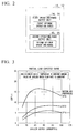
- Fig. 2 is a block diagram illustrating the configurations of the group control devices 11 and 21.
- the group control devices 11 and 21 respectively include first operating-range output units 14 and 24 that output a load range in which a coefficient of performance corresponding to the number of operating heat source units 12 and 22 is equal to or greater than a predetermined value as a first proper operating range to the number-of-units control device 30 based on the COP information which is a characteristic value indicating the relation between the coefficient of performance and the load ratio of the heat source units 12 and 22.
- the group control devices 11 and 21 respectively include second operating-range output units 15 and 25 that output a load range in which a coefficient of performance corresponding to the predetermined number of units greater than the operating heat source units 12 and 22 is equal to or greater than a predetermined value as a second proper operating range to the number-of-units control device 30 based on the COP information.
- the number-of-units control device 30 increases the number of activated units of each of the heat source groups 10 and 20 when a requested load exceeds the first proper operating range.
- the heat source system 100 sets an optimum load range corresponding to the number of operating units among the heat source units 12 and 22 respectively connected to the group control devices 11 and 21 and an operatable load range corresponding to 1 + the number of operating units as data to be transmitted from the group control devices 11 and 21 to the number-of-units control device 30.
- an optimum load range for one unit and an operatable load range for two units are set as an optimum load range and an operatable load range of the whole group.
- the heat source system 100 sets an optimum load range and an operatable load range for one unit as data to be transmitted from the group control devices 11 and 21 to the number-of-units control device 30.
- the number-of-units control device 30 sets optimum load ranges and operatable load ranges of both of the heat source groups 10 and 20 using the following Expressions (1) to (12).
- Loh_gkui and Lol_gkui are a Hi-side and a Lo-side of the optimum load range of each of the heat source units 12 and 22
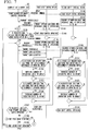
- Fig. 3 is a diagram illustrating COP characteristics applied to the heat source system 100.
- Information regarding the COP characteristics indicates a relation between the coefficient of performance and a load ratio of each of the heat source units 12 and 22 and includes data received from the unit-integrated control device 23.
- the horizontal axis represents a chiller output capacity and the vertical axis represents a COP value.
- the COP has a parabolic shape according to an increase in the chiller output capacity when outside air temperature is, for example, 15°C, 25°C, and 32°C.
- the proper operating range is a load range equal to or greater than a predetermined value.
- Fig. 4 is a diagram illustrating power consumption amount characteristics applied to the heat source system 100.
- the horizontal axis represents a chiller output capacity and the vertical axis represents an inverter input.
- power consumption increases directly proportionally with an increase in the chiller output capacity when an outside air temperature is, for example, 15°C, 25°C, and 32°C.
- the proper operating range is a load range equal to or less than a predetermined value.
- Fig. 5 is a flowchart for describing a basic control operation of the heat source system 100. As illustrated in Fig. 5 , when the control starts, the number-of-units control device 30 first determines whether the operating heat source unit is in either of the heat source groups 10 and 20 (S101).
- the number-of-units control device 30 decides the optimum load range and the operatable load range of both of the heat source groups 10 and 20 according to the above-described Expressions (1) to (6) (S102).
- the number-of-units control device 30 decides the optimum load range and the operatable load range of both of the heat source groups 10 and 20 according to the above-described Expressions (7) to (12) (S103).
- Figs. 6 and 7 are flowchart for describing a specific control operation of the heat source system 100.
- Fig. 6 illustrates a case in which the first heat source group 10 works first.
- the number-of-units control device 30 first starts operating and issues a group operating instruction (S111).
- the group operating instruction is transmitted to the first group control device 11, and thus the first group control device 11 starts operating (S112).
- the first group control device 11 transmits the optimum load range and the operatable load range calculated from Expressions (1) to (6) to the number-of-units control device 30 (S113).
- the optimum load range and the operatable load range are periodically transmitted to the number-of-units control device 30.
- the second group control device 21 transmits the optimum load range and the operatable load range calculated according to Expressions (7) to (12) to the number-of-units control device 30 (S114).
- the optimum load range and the operatable load range are periodically transmitted to the number-of-units control device 30.
- the number-of-units control device 30 determines whether a request load is greater than the optimum load range during the operating (S115).
- the second group control device 21 starts operating when the number-of-units control device 30 determines that the request load is greater than the optimum load range during the operating (S116).
- the first group control device 11 periodically transmits the optimum load range and the operatable load range calculated according to Expressions (1) to (6) to the number-of-units control device 30 (S 117).
- the second group control device 21 periodically transmits the optimum load range and the operatable load range calculated according to Expressions (1) to (6) (S118).
- the number-of-units control device 30 transmits load allocation to the first group control device 11 and the second group control device 21.
- the first group control device 11 determines whether the allocated load is greater than a load range that can be handled with the number of operating units (S119). When the first group control device 11 determines that the load allocated by the number-of-units control device 30 is greater than the load range that can be handled with the number of operating units, the first group control device 11 increases the number of operating units in the heat source group (S120). Conversely, when the first group control device 11 determines that the load allocated by the number-of-units control device 30 is not greater than the load range that can be handled with the number of operating units, the first group control device 11 does not change the number of operating units.
- the second group control device 21 determines whether the allocated load is greater than the load range that can be handled with the number of operating units (S121). When the second group control device 21 determines that the load allocated by the number-of-units control device 30 is greater than the load range that can be handled with the number of operating units, the second group control device 21 increases the number of operating units in the heat source group (S122). Conversely, when the load allocated by the number-of-units control device 30 is not greater than the load range that can be handled with the number of operating units, the second group control device 21 does not change the number of operating units.
- the first group control device 11 determines whether the allocated load is less than the load range that can be handled with the number of operating units (S123). When the first group control device 11 determines that the load allocated by the number-of-units control device 30 is less than the load range that can be handled with the number of operating units, the first group control device 11 decreases the number of operating units in the heat source group (S124). Conversely, when the load allocated by the number-of-units control device 30 is not less than the load range that can be handled with the number of operating units, the first group control device 11 does not change the number of operating units.
- the second group control device 21 determines whether the allocated load is less than the load range that can be handled with the number of operating units (S125). When the second group control device 21 determines that the load allocated by the number-of-units control device 30 is less than the load range that can be handled with the number of operating units, the second group control device 21 decreases the number of operating units in the heat source group (S126). When the second group control device 21 determines that the load allocated by the number-of-units control device 30 is not less than the load range that can be handled with the number of operating units, the second group control device 21 does not change the number of operating units.
- the number-of-units control device 30 determines whether the requested load is less than the optimum load range during the operating (S127). When the number-of-units control device 30 determines that the requested load is less than the optimum load range during the operating, a stop instruction is issued to the first group control device 11, and thus the operating of the first group control device 11 ends (S128). At this time, when the operating group is only one first heat source group 10, the stop instruction is not issued.
- Fig. 7 illustrates a case in which the second heat source group 20 works first.
- the control starts, the number-of-units control device 30 first starts operating and issues a group operating instruction (S141).
- the group operating instruction is transmitted to the second group control device 21, and thus the second group control device 21 starts operating (S142).
- the second group control device 21 transmits the optimum load range and the operatable load range calculated from Expressions (1) to (6) to the number-of-units control device 30 (S143).
- the optimum load range and the operatable load range are periodically transmitted to the number-of-units control device 30.
- the first group control device 11 transmits the optimum load range and the operatable load range calculated according to Expressions (7) to (12) to the number-of-units control device 30 (S144).
- the optimum load range and the operatable load range are periodically transmitted to the number-of-units control device 30.
- the number-of-units control device 30 determines whether a request load is greater than the optimum load range during the operating (S145).
- the first group control device 11 starts operating when the number-of-units control device 30 determines that the request load is greater than the optimum load range during the operating (S146).
- the second group control device 21 periodically transmits the optimum load range and the operatable load range calculated according to Expressions (1) to (6) (S148).
- the number-of-units control device 30 transmits load allocation to the first group control device 11 and the second group control device 21.
- the first group control device 11 determines whether the allocated load is greater than a load range that can be handled with the number of operating units (S149). When the first group control device 11 determines that the load allocated by the number-of-units control device 30 is greater than the load range that can be handled with the number of operating units, the first group control device 11 increases the number of operating units in the heat source group (S150). Conversely, when the first group control device 11 determines that the load allocated by the number-of-units control device 30 is not greater than the load range that can be handled with the number of operating units, the first group control device 11 does not change the number of operating units.
- the second group control device 21 determines whether the allocated load is greater than the load range that can be handled with the number of operating units (S151). When the second group control device 21 determines that the load allocated by the number-of-units control device 30 is greater than the load range that can be handled with the number of operating units, the second group control device 21 increases the number of operating units in the heat source group (S152). Conversely, when the second group control device 21 determines that the load allocated by the number-of-units control device 30 is not greater than the load range that can be handled with the number of operating units, the second group control device 21 does not change the number of operating units.
- the first group control device 11 determines whether the allocated load is less than the load range that can be handled with the number of operating units (S153). When the first group control device 11 determines that the load allocated by the number-of-units control device 30 is less than the load range that can be handled with the number of operating units, the first group control device 11 decreases the number of operating units in the heat source group (S154). Conversely, when the first group control device 11 determines that the load allocated by the number-of-units control device 30 is not less than the load range that can be handled with the number of operating units, the first group control device 11 does not change the number of operating units.
- the second group control device 21 determines whether the allocated load is less than the load range that can be handled with the number of operating units (S155). When the second group control device 21 determines that the load allocated by the number-of-units control device 30 is less than the load range that can be handled with the number of operating units, the second group control device 21 decreases the number of operating units in the heat source group (S156). When the second group control device 21 determines that the load allocated by the number-of-units control device 30 is not less than the load range that can be handled with the number of operating units, the second group control device 21 does not change the number of operating units.
- the number-of-units control device 30 determines whether the requested load is less than the optimum load range during the operating (S157). When the number-of-units control device 30 determines that the requested load is less than the optimum load range during the operating, a stop instruction is issued to the second group control device 21, and thus the operating of the second group control device 21 ends (S 158). At this time, when the number-of-units control device 30 determines that the operating group is only one second heat source group 20, the stop instruction is not issued.
- the number-of-units control device 30 determines whether only the first heat source group 10 is operating (S 159). When the number-of-units control device 30 determines that only the first heat source group 10 is operating, the process proceeds to (S115) illustrated in Fig. 6 . When the number-of-units control device 30 determines that only the first heat source group 10 is not operating, the number-of-units control device 30 determines whether only the second heat source group 20 is operating (S160). When the number-of-units control device 30 determines that only the second heat source group 20 is operating, the process proceeds to (S 145). When the number-of-units control device 30 determines that only the second heat source group 20 is not operating, the process proceeds to (S 147) to repeat the routine.
- the heat source system 100 first performs the process of increasing the number of heat source groups when the load departs from the optimum load range. Accordingly, in the heat source system 100, when only one heat source unit is operating between the heat source units 12 and 22 connected to the heat source groups 10 and 20, the number of operating target heat source groups can first be increased. Therefore, even when the load can be equally distributed to the heat source groups 10 and 20, control can be performed such that the number of operating heat source units 12 and 22 connected to the heat source groups 10 and 20 is not changed suddenly.
- the control of the number of units and the load distribution in the plurality of heat source groups 10 and 20 can be performed without considerable change in the number of operating heat source units 12 and 22 connected to the heat source groups 10 and 20. Further, the optimum operating state in which the power consumption is small can be kept as the operating state of the heat source units 12 and 22.
- Fig. 8 is a flowchart for describing a basic control operation of a heat source system 100 according to a second embodiment.
- the heat source system 100 increases the number of operating heat source units in the heat source groups 10 and 20 and updates the optimum load range and the operatable load range.
- the load range that can be handled with the whole heat source group is assumed to be 100%
- the load distribution from the number-of-units control device 30 is greater than 10% in the case of an operating state of one unit (the operatable load range corresponding to the operating state is 10%)
- the number of operating units is updated from one to two and the optimum load range for two heat source units and the operatable load range for three heat source units are assumed to be the optimum load range and the operatable load range of the whole heat source group.
- the first group control device 11 and the second group control device 21 determine whether the load distribution is greater than a Hi-side of an operatable load range of the operating heat source units (S201).
- the first group control device 11 and the second group control device 21 increase the number of operating heat source units and update the optimum load range and the operatable load range of both of the heat source groups 10 and 20.
- the first group control device 11 and the second group control device 21 end the process.
- the heat source system 100 can automatically increase the number of operating heat source units of the heat source groups 10 and 20 by increasing the load allocation once all the subordinate heat source groups 10 and 20 are in an operating state of one heat source unit from the viewpoint of the number-of-units control device 30.
- Fig. 9 is a flowchart for describing a basic control operation of a heat source system 100 according to a third embodiment.
- the heat source system 100 decreases the number of operating heat source units in the heat source groups 10 and 20 and updates the optimum load range and the operatable load range.
- the load range that can be handled with both of the heat source groups is assumed to be 100%
- the load distribution from the number-of-units control device 30 is less than 20% in the case of an operating state of two units (the operatable load range corresponding to the operating state is 20%)
- the number of operating units is updated from two to one and the optimum load range for one heat source unit and the operatable load range for two heat source units are assumed to be the optimum load range and the operatable load range of both of the heat source groups.
- the first group control device 11 and the second group control device 21 determine whether the load distribution is less than a Lo-side of an operatable load range of the operating heat source units (S301).
- the first group control device 11 and the second group control device 21 decrease the number of operating heat source units and update the optimum load range and the operatable load range of both of the heat source groups 10 and 20.
- the first group control device 11 and the second group control device 21 end the process.
- the heat source system and the heat source control method are not limited to the above-described embodiments, but can be appropriately modified or improved.
Landscapes
- Engineering & Computer Science (AREA)
- Chemical & Material Sciences (AREA)
- Combustion & Propulsion (AREA)
- Mechanical Engineering (AREA)
- General Engineering & Computer Science (AREA)
- Physics & Mathematics (AREA)
- Thermal Sciences (AREA)
- Fuzzy Systems (AREA)
- Mathematical Physics (AREA)
- Signal Processing (AREA)
- Computer Hardware Design (AREA)
- Air Conditioning Control Device (AREA)
Abstract
Description
- The present invention relates to a heat source control device, a heat source system, and a heat source control method.
- Priority is claimed on
Japanese Patent Application No. 2013-228348, filed November 1, 2013 - In large buildings, chilled and hot water systems in which a plurality of heat sinks and heat sources are provided in parallel and secondary-side heat load sources such as air conditioners are connected to the heat sinks and heat sources are used. Each of the heat sinks and heat sources includes a chilled and hot water pump circulating chilled and hot water generated by each of the heat sinks and heat sources.
- In such chilled and hot water systems, necessary flow rates of chilled and hot water are changed to handle heat loads according to secondary-side loads. Accordingly, in such chilled and hot water systems, flow rates of chilled and hot water to be supplied to secondary-side heat load sources have to be controlled.
- As such chilled and hot water control methods, there are methods of controlling bypass flow rates of secondary-side heat load sources and controlling the numbers of heat sinks and heat sources. In such a method of controlling the numbers of heat sinks and heat sources, the number of operating heat sinks and heat sources is selected in accordance with schemes considering flow rates, heat amounts, and both of flow rates and heat amounts.
- In this case, chilled and hot water pumps of the used heat sinks and heat sources circulate chilled and hot water by changing flow rates according to loads.
- As technologies related to such a background, various technologies are known (for example, see Patent Literature 1).
- For example,
Patent Literature 1 discloses a heat sink and heat source output distribution control method of a chilled and hot water system that includes a plurality of heat sinks and heat sources disposed in parallel, chilled and hot water pumps included in the heat sinks and heat sources, and a secondary-side heat load source connected to the plurality of heat sinks and heat sources. More specifically, in the heat sink and heat source output distribution control method, the number of heat sinks and heat sources to be used is selected according to heat loads of secondary-side heat sources. In the heat sink and heat source output distribution control method, when a plurality of heat sinks and heat sources are used, the heat sinks and heat sources to be used are divided into two groups which each have one heat sink and one heat source or a plurality of heat sinks and heat sources, and a ratio of a flow rate of chilled and hot water of the heat sinks and heat sources of both groups to a flow rate of chilled and hot water supplied to the secondary-side heat load source is changed so that a sum system COP of the two groups of the heat sinks and heat sources is the maximum. The flow rate is changed in a direction in which a ratio of one group increases in accordance with a predetermined period and the system COP is calculated. When the system COP increases more than the system COP before the change, the flow rate is changed in the same direction. When the system COP decreases, the flow rate is changed in the opposite direction. In this way, according to the heat sink and heat source output distribution control method, the heat sinks and heat sources work with the maximum efficiency from the viewpoint of the entire system, and thus power consumption can be reduced. - [Patent Literature 1]
Japanese Patent No. 4435651 - In the invention described in
Patent Literature 1, when the numbers of heat sinks and heat sources increase, a control period may increase, and thus there is a possibility that a load state to be handled is changed. Therefore, in the invention described inPatent Literature 1, search results may not always be optimum. - In the invention described in
Patent Literature 1, when group control is performed and the same function of a number-of-units control function mounted on a high-order control device is mounted, a load range that can be handled with one group becomes broader than a load range that can be handled with one unit. Therefore, in the invention described inPatent Literature 1, for example, when ten units are operating in an operating group and another group is newly activated in this state, sudden changes in control may be performed in such a manner that the number of operating units of the operating group is changed from 10 to 5 and the number of operating units of the newly activated group is changed from 0 to 5. Therefore, control may not be performed to prevent the number of operating units connected to the group from changing suddenly. - According to a first aspect of the present invention, there is provided a heat source control device including: a plurality of group control units configured to perform start/stop and load allocation of a plurality of heat source units corresponding to heat source groups of the plurality of heat source units; and a number-of-units control unit configured to perform start/stop and load allocation of the heat source groups. The group control unit includes a first operating-range output unit configured to output a load range in which one of characteristic values of the heat source units corresponding to the number of operating heat source units is within a predetermined range as a first proper operating range to the number-of-units control unit based on the characteristic values of the heat source units, and a second operating-range output unit configured to output a load range in which another of the characteristic values is in the predetermined range as a second proper operating range to the number-of-units control unit. The number-of-units control unit increases the number of activated heat source groups when a requested load exceeds the first proper operating range.
- According to a second aspect of the present invention, in the heat source control device according to the first aspect, the first operating-range output unit may use COP information indicating a relation between a coefficient of performance and a load ratio as the characteristic value and output a load range in which one of the characteristic values corresponding to the number of operating heat source units is equal to or greater than a predetermined value as the first proper operating range to the number-of-units control unit. The second operating-range output unit may output a load range in which another of the characteristic values is equal to or greater than the predetermined value as the second proper operating range to the number-of-units control unit.
- According to a third aspect of the present invention, in the heat source control device according to the first aspect, the first operating-range output unit may use inverter input information as the characteristic value and output a load range in which one of the characteristic values corresponding to the number of operating heat source units is equal to or less than a predetermined value as the first proper operating range to the number-of-units control unit. The second operating-range output unit may output a load range in which another of the characteristic values is equal to or less than the predetermined value as the second proper operating range to the number-of-units control unit.
- According to a fourth aspect of the present invention, in the heat source control device according to any one of the first to third aspects, the group control unit may set, as transmission data from the group control unit, an optimum load range corresponding to the number of operating heat source units among the connected heat source units and an operatable load range corresponding to 1 + the number of operating heat source units.
- According to a fifth aspect of the present invention, in the heat source control device according to any one of the first to fourth aspects, when load distribution to the heat source groups from the number-of-units control unit is greater than the operatable load range for the number of operating heat source units, the number of operating heat source units in the heat source group may be increased and the optimum load range and the operatable load range may be updated.
- According to a sixth aspect of the present invention, in the heat source control device according to any one of the first to fifth aspects, when load distribution to the heat source groups from the number-of-units control unit is less than the operatable load range for the number of operating heat source units, the number of operating heat source units in the heat source group may be decreased and the optimum load range and the operatable load range may be updated.
- According to a seventh aspect of the present invention, there is provided a heat source system including: the heat source control device according to any one of the first to sixth aspects; and heat source groups of the plurality of heat source units.
- According to an eighth aspect of the present invention, there is provided a heat source control method including: a plurality of group control steps of performing start/stop and load allocation of a plurality of heat source units corresponding to heat source groups of the plurality of heat source units; and a number-of-units control step of performing start/stop and load allocation of the heat source groups. The group control step includes a first operating-range output step of outputting a load range in which one of characteristic values of the heat source units corresponding to the number of operating heat source units is within a predetermined range as a first proper operating range in the number-of-units control step based on the characteristic values of the heat source units, and a second operating-range output step of outputting a load range in which another of the characteristic values is in the predetermined range as a second proper operating range in the number-of-units control step. In the number-of-units control step, the number of activated heat source groups is increased when a requested load exceeds the first proper operating range.
- In the overview of the first to eighth aspects of the present invention, not all of the characteristics necessary in the present invention are listed. Sub-combinations of such characteristic groups can also be aspects of the present invention.
- According to the heat source control device, the heat source system, and the heat source control method described above, it is possible to control the number of operating heat source units included in the plurality of heat source groups without sudden changes.
-
-
Fig. 1 is a diagram illustrating an example of the system configuration of aheat source system 100 according to a first embodiment. -
Fig. 2 is a block diagram illustrating the configurations ofgroup control devices -
Fig. 3 is a diagram illustrating COP characteristics applied to theheat source system 100. -
Fig. 4 is a diagram illustrating power consumption amount characteristics applied to theheat source system 100. -
Fig. 5 is a flowchart for describing a basic control operation of theheat source system 100. -
Fig. 6 is a flowchart for describing a specific control operation of theheat source system 100. -
Fig. 7 is a flowchart for describing the specific control operation of theheat source system 100. -
Fig. 8 is a flowchart for describing a basic control operation of aheat source system 100 according to a second embodiment. -
Fig. 9 is a flowchart for describing a basic control operation of aheat source system 100 according to a third embodiment. - Hereinafter, the present invention will be described according to embodiments of the invention. However, the following embodiments do not limit the invention within the scope of the claims, and not all of the combinations of the characteristics described in the embodiments are requisites for the solution of the invention.
-
Fig. 1 is a diagram illustrating an example of the system configuration of aheat source system 100 according to a first embodiment. Here, theheat source system 100 is a system that controls a plurality of heat sources. - The
heat source system 100 includes a firstheat source group 10, a firstgroup control device 11, a secondheat source group 20, a secondgroup control device 21, and a number-of-units control device 30. - The first
heat source group 10 includes a plurality ofheat source units 12. Here, theheat source unit 12 is a unit that includes a heat source device and a unit-integratedcontrol device 13. An input side of eachheat source unit 12 is connected to communicate with awater inlet 41 and an output side thereof is connected to communicate with a water outlet 42. The output side of eachheat source unit 12 is connected to the firstgroup control device 11 and the number-of-units control device 30. - When the first
group control device 11 controls theheat source units 12, the firstgroup control device 11 receives necessary data from the unit-integratedcontrol device 13 and transmits control data to the unit-integratedcontrol device 13. Then, the firstgroup control device 11 performs start/stop and load allocation of eachheat source unit 12. - The second
heat source group 20 is connected to the firstheat source group 10 in parallel and includes a plurality ofheat source units 22. Here, theheat source unit 22 is a unit that includes a heat source device and a unit-integratedcontrol device 23. An input side of eachheat source unit 22 is connected to communicate with thewater inlet 41 and an output side thereof is connected to communicate with the water outlet 42. The output side of eachheat source unit 22 is connected to the secondgroup control device 21 and the number-of-units control device 30. When the secondgroup control device 21 controls theheat source units 22, the secondgroup control device 21 receives necessary data from the unit-integratedcontrol device 23 and transmits control data to the unit-integratedcontrol device 23. Here, the data received from the unit-integratedcontrol device 23 also includes COP information indicating a relation between a coefficient of performance and a load ratio of theheat source units - The first
group control device 11 performs start/stop and load allocation of eachheat source unit 22. - The number-of-
units control device 30 performs start/stop and load allocation of the firstheat source group 10 and the secondheat source group 20. From the viewpoint of the number-of-units control device 30, the firstheat source group 10 and the secondheat source group 20 are each treated like a large-capacity chiller. -
Fig. 2 is a block diagram illustrating the configurations of thegroup control devices Fig. 2 , thegroup control devices heat source units units control device 30 based on the COP information which is a characteristic value indicating the relation between the coefficient of performance and the load ratio of theheat source units - The
group control devices range output units heat source units units control device 30 based on the COP information. - The number-of-
units control device 30 increases the number of activated units of each of theheat source groups - The
heat source system 100 sets an optimum load range corresponding to the number of operating units among theheat source units group control devices group control devices units control device 30. - Specifically, for example, when ten
heat source units 12 are connected to the firstgroup control device 11 and one heat source unit is operating, an optimum load range for one unit and an operatable load range for two units are set as an optimum load range and an operatable load range of the whole group. - When all of the units stop among the
heat source units group control devices heat source system 100 sets an optimum load range and an operatable load range for one unit as data to be transmitted from thegroup control devices units control device 30. - When the operating heat source units are in the
heat source groups units control device 30 sets optimum load ranges and operatable load ranges of both of theheat source groups - In Expressions (1) to (6), Loh_gi and Lol_gi are a Hi-side and a Lo-side of the optimum load range of each of the
heat source groups heat source units 


- In Expressions (7) to (12), Loh_gi and Lol_gi are a Hi-side and a Lo-side of the optimum load range of each of the
heat source groups heat source units 


-
Fig. 3 is a diagram illustrating COP characteristics applied to theheat source system 100. Information regarding the COP characteristics indicates a relation between the coefficient of performance and a load ratio of each of theheat source units control device 23. InFig. 3 , the horizontal axis represents a chiller output capacity and the vertical axis represents a COP value. As illustrated inFig. 3 , in the COP characteristics, the COP has a parabolic shape according to an increase in the chiller output capacity when outside air temperature is, for example, 15°C, 25°C, and 32°C. At this time, the proper operating range is a load range equal to or greater than a predetermined value. -
Fig. 4 is a diagram illustrating power consumption amount characteristics applied to theheat source system 100. InFig. 4 , the horizontal axis represents a chiller output capacity and the vertical axis represents an inverter input. As illustrated inFig. 4 , in power consumption amount characteristics, power consumption increases directly proportionally with an increase in the chiller output capacity when an outside air temperature is, for example, 15°C, 25°C, and 32°C. At this time, the proper operating range is a load range equal to or less than a predetermined value. -
Fig. 5 is a flowchart for describing a basic control operation of theheat source system 100. As illustrated inFig. 5 , when the control starts, the number-of-units control device 30 first determines whether the operating heat source unit is in either of theheat source groups 10 and 20 (S101). - When the operating unit is in either of the
heat source groups units control device 30 decides the optimum load range and the operatable load range of both of theheat source groups - When the operating unit is not present in either of the
heat source groups units control device 30 decides the optimum load range and the operatable load range of both of theheat source groups -
Figs. 6 and7 are flowchart for describing a specific control operation of theheat source system 100.Fig. 6 illustrates a case in which the firstheat source group 10 works first. As illustrated inFig. 6 , when the control starts, the number-of-units control device 30 first starts operating and issues a group operating instruction (S111). The group operating instruction is transmitted to the firstgroup control device 11, and thus the firstgroup control device 11 starts operating (S112). - The first
group control device 11 transmits the optimum load range and the operatable load range calculated from Expressions (1) to (6) to the number-of-units control device 30 (S113). The optimum load range and the operatable load range are periodically transmitted to the number-of-units control device 30. - At this time, the second
group control device 21 transmits the optimum load range and the operatable load range calculated according to Expressions (7) to (12) to the number-of-units control device 30 (S114). The optimum load range and the operatable load range are periodically transmitted to the number-of-units control device 30. - The number-of-
units control device 30 determines whether a request load is greater than the optimum load range during the operating (S115). The secondgroup control device 21 starts operating when the number-of-units control device 30 determines that the request load is greater than the optimum load range during the operating (S116). - Thereafter, the first
group control device 11 periodically transmits the optimum load range and the operatable load range calculated according to Expressions (1) to (6) to the number-of-units control device 30 (S 117). - The second
group control device 21 periodically transmits the optimum load range and the operatable load range calculated according to Expressions (1) to (6) (S118). - Next, the number-of-
units control device 30 transmits load allocation to the firstgroup control device 11 and the secondgroup control device 21. The firstgroup control device 11 determines whether the allocated load is greater than a load range that can be handled with the number of operating units (S119). When the firstgroup control device 11 determines that the load allocated by the number-of-units control device 30 is greater than the load range that can be handled with the number of operating units, the firstgroup control device 11 increases the number of operating units in the heat source group (S120). Conversely, when the firstgroup control device 11 determines that the load allocated by the number-of-units control device 30 is not greater than the load range that can be handled with the number of operating units, the firstgroup control device 11 does not change the number of operating units. - The second
group control device 21 determines whether the allocated load is greater than the load range that can be handled with the number of operating units (S121). When the secondgroup control device 21 determines that the load allocated by the number-of-units control device 30 is greater than the load range that can be handled with the number of operating units, the secondgroup control device 21 increases the number of operating units in the heat source group (S122). Conversely, when the load allocated by the number-of-units control device 30 is not greater than the load range that can be handled with the number of operating units, the secondgroup control device 21 does not change the number of operating units. - Subsequently, the first
group control device 11 determines whether the allocated load is less than the load range that can be handled with the number of operating units (S123). When the firstgroup control device 11 determines that the load allocated by the number-of-units control device 30 is less than the load range that can be handled with the number of operating units, the firstgroup control device 11 decreases the number of operating units in the heat source group (S124). Conversely, when the load allocated by the number-of-units control device 30 is not less than the load range that can be handled with the number of operating units, the firstgroup control device 11 does not change the number of operating units. - The second
group control device 21 determines whether the allocated load is less than the load range that can be handled with the number of operating units (S125). When the secondgroup control device 21 determines that the load allocated by the number-of-units control device 30 is less than the load range that can be handled with the number of operating units, the secondgroup control device 21 decreases the number of operating units in the heat source group (S126). When the secondgroup control device 21 determines that the load allocated by the number-of-units control device 30 is not less than the load range that can be handled with the number of operating units, the secondgroup control device 21 does not change the number of operating units. - The number-of-
units control device 30 determines whether the requested load is less than the optimum load range during the operating (S127). When the number-of-units control device 30 determines that the requested load is less than the optimum load range during the operating, a stop instruction is issued to the firstgroup control device 11, and thus the operating of the firstgroup control device 11 ends (S128). At this time, when the operating group is only one firstheat source group 10, the stop instruction is not issued. - When the number-of-
units control device 30 determines that the requested load is not less than the optimum load range during the operating, the number-of-units control device 30 determines whether only the secondheat source group 20 is operating (S129). When the number-of-units control device 30 determines that only the secondheat source group 20 is operating, the process proceeds to (S 145) illustrated inFig. 7 . When the number-of-units control device 30 determines that only the secondheat source group 20 is not operating, the number-of-units control device 30 determines whether only the firstheat source group 10 is operating (S130). When the number-of-units control device 30 determines that only the firstheat source group 10 is operating, the process proceeds to (S 115). When the number-of-units control device 30 determines that only the firstheat source group 10 is not operating, the process proceeds to (S117) to repeat the routine. -
Fig. 7 illustrates a case in which the secondheat source group 20 works first. As illustrated inFig. 7 , when the control starts, the number-of-units control device 30 first starts operating and issues a group operating instruction (S141). The group operating instruction is transmitted to the secondgroup control device 21, and thus the secondgroup control device 21 starts operating (S142). - The second
group control device 21 transmits the optimum load range and the operatable load range calculated from Expressions (1) to (6) to the number-of-units control device 30 (S143). The optimum load range and the operatable load range are periodically transmitted to the number-of-units control device 30. - At this time, the first
group control device 11 transmits the optimum load range and the operatable load range calculated according to Expressions (7) to (12) to the number-of-units control device 30 (S144). The optimum load range and the operatable load range are periodically transmitted to the number-of-units control device 30. - The number-of-
units control device 30 determines whether a request load is greater than the optimum load range during the operating (S145). The firstgroup control device 11 starts operating when the number-of-units control device 30 determines that the request load is greater than the optimum load range during the operating (S146). - Thereafter, the first
group control device 11 periodically transmits the optimum load range and the operatable load range calculated according to Expressions (1) to (6) to the number-of-units control device 30 (S147). - The second
group control device 21 periodically transmits the optimum load range and the operatable load range calculated according to Expressions (1) to (6) (S148). - Next, the number-of-
units control device 30 transmits load allocation to the firstgroup control device 11 and the secondgroup control device 21. The firstgroup control device 11 determines whether the allocated load is greater than a load range that can be handled with the number of operating units (S149). When the firstgroup control device 11 determines that the load allocated by the number-of-units control device 30 is greater than the load range that can be handled with the number of operating units, the firstgroup control device 11 increases the number of operating units in the heat source group (S150). Conversely, when the firstgroup control device 11 determines that the load allocated by the number-of-units control device 30 is not greater than the load range that can be handled with the number of operating units, the firstgroup control device 11 does not change the number of operating units. - The second
group control device 21 determines whether the allocated load is greater than the load range that can be handled with the number of operating units (S151). When the secondgroup control device 21 determines that the load allocated by the number-of-units control device 30 is greater than the load range that can be handled with the number of operating units, the secondgroup control device 21 increases the number of operating units in the heat source group (S152). Conversely, when the secondgroup control device 21 determines that the load allocated by the number-of-units control device 30 is not greater than the load range that can be handled with the number of operating units, the secondgroup control device 21 does not change the number of operating units. - Subsequently, the first
group control device 11 determines whether the allocated load is less than the load range that can be handled with the number of operating units (S153). When the firstgroup control device 11 determines that the load allocated by the number-of-units control device 30 is less than the load range that can be handled with the number of operating units, the firstgroup control device 11 decreases the number of operating units in the heat source group (S154). Conversely, when the firstgroup control device 11 determines that the load allocated by the number-of-units control device 30 is not less than the load range that can be handled with the number of operating units, the firstgroup control device 11 does not change the number of operating units. - The second
group control device 21 determines whether the allocated load is less than the load range that can be handled with the number of operating units (S155). When the secondgroup control device 21 determines that the load allocated by the number-of-units control device 30 is less than the load range that can be handled with the number of operating units, the secondgroup control device 21 decreases the number of operating units in the heat source group (S156). When the secondgroup control device 21 determines that the load allocated by the number-of-units control device 30 is not less than the load range that can be handled with the number of operating units, the secondgroup control device 21 does not change the number of operating units. - The number-of-
units control device 30 determines whether the requested load is less than the optimum load range during the operating (S157). When the number-of-units control device 30 determines that the requested load is less than the optimum load range during the operating, a stop instruction is issued to the secondgroup control device 21, and thus the operating of the secondgroup control device 21 ends (S 158). At this time, when the number-of-units control device 30 determines that the operating group is only one secondheat source group 20, the stop instruction is not issued. - When the number-of-
units control device 30 determines that the requested load is not less than the optimum load range during the operating, the number-of-units control device 30 determines whether only the firstheat source group 10 is operating (S 159). When the number-of-units control device 30 determines that only the firstheat source group 10 is operating, the process proceeds to (S115) illustrated inFig. 6 . When the number-of-units control device 30 determines that only the firstheat source group 10 is not operating, the number-of-units control device 30 determines whether only the secondheat source group 20 is operating (S160). When the number-of-units control device 30 determines that only the secondheat source group 20 is operating, the process proceeds to (S 145). When the number-of-units control device 30 determines that only the secondheat source group 20 is not operating, the process proceeds to (S 147) to repeat the routine. - As described above, the
heat source system 100 according to the embodiment first performs the process of increasing the number of heat source groups when the load departs from the optimum load range. Accordingly, in theheat source system 100, when only one heat source unit is operating between theheat source units heat source groups heat source groups heat source units heat source groups - In the
heat source system 100 according to the embodiment, the control of the number of units and the load distribution in the plurality ofheat source groups heat source units heat source groups heat source units - Next, a second embodiment will be described with reference to
Fig. 8 . The same reference numerals are given to the same portions as those of the first embodiment. The description thereof will be omitted and only differences will be described.Fig. 8 is a flowchart for describing a basic control operation of aheat source system 100 according to a second embodiment. - When the load distribution to the
heat source groups units control device 30 is greater than an operatable load range of the number of operating heat source units, theheat source system 100 increases the number of operating heat source units in theheat source groups heat source system 100, for example, when tenheat source units 12 are connected to the first group control device 11 (the load range that can be handled with the whole heat source group is assumed to be 100%) and the load distribution from the number-of-units control device 30 is greater than 10% in the case of an operating state of one unit (the operatable load range corresponding to the operating state is 10%), the number of operating units is updated from one to two and the optimum load range for two heat source units and the operatable load range for three heat source units are assumed to be the optimum load range and the operatable load range of the whole heat source group. - As illustrated in
Fig. 8 , when control starts, the firstgroup control device 11 and the secondgroup control device 21 determine whether the load distribution is greater than a Hi-side of an operatable load range of the operating heat source units (S201). - When the load distribution is greater than the Hi-side of the operatable load range of the operating heat source units, the first
group control device 11 and the secondgroup control device 21 increase the number of operating heat source units and update the optimum load range and the operatable load range of both of theheat source groups - At this time, when the load distribution is not greater than the Hi-side of the operatable load range of the operating heat source units, the first
group control device 11 and the secondgroup control device 21 end the process. - The
heat source system 100 according to the embodiment can automatically increase the number of operating heat source units of theheat source groups heat source groups units control device 30. - Next, a third embodiment will be described with reference to
Fig. 9 . The same reference numerals are given to the same portions as those of the first embodiment. The description thereof will be omitted and only differences will be described.Fig. 9 is a flowchart for describing a basic control operation of aheat source system 100 according to a third embodiment. - When the load distribution to the heat source groups from the number-of-
units control device 30 is less than an operatable load range of the number of operating heat source units, theheat source system 100 decreases the number of operating heat source units in theheat source groups group control devices 11 and 21 (the load range that can be handled with both of the heat source groups is assumed to be 100%) and the load distribution from the number-of-units control device 30 is less than 20% in the case of an operating state of two units (the operatable load range corresponding to the operating state is 20%), the number of operating units is updated from two to one and the optimum load range for one heat source unit and the operatable load range for two heat source units are assumed to be the optimum load range and the operatable load range of both of the heat source groups. - As illustrated in
Fig. 9 , when control starts, the firstgroup control device 11 and the secondgroup control device 21 determine whether the load distribution is less than a Lo-side of an operatable load range of the operating heat source units (S301). - When the load distribution is less than the Lo-side of the operatable load range of the operating heat source units, the first
group control device 11 and the secondgroup control device 21 decrease the number of operating heat source units and update the optimum load range and the operatable load range of both of theheat source groups - At this time, when the load distribution is not less than the Lo-side of the operatable load range of the operating heat source units, the first
group control device 11 and the secondgroup control device 21 end the process. - The
heat source system 100 according to the embodiment can automatically decrease the number of operating heat source units of theheat source groups units control device 30. - The heat source system and the heat source control method are not limited to the above-described embodiments, but can be appropriately modified or improved.
- It is possible to control the number of operating heat source units included in the plurality of heat source groups without sudden changes.
-
- 100
- Heat source system
- 10
- First heat source group
- 11
- First group control device
- 12, 22
- Heat source unit
- 13, 23
- Unit-integrated control device
- 14, 24
- First operating-range output unit
- 15, 25
- Second operating-range output unit
- 20
- Second heat source group
- 21
- Second group control device
- 30
- Number-of-units control device
- 41
- Water inlet
- 42
- Water outlet
Claims (8)
- A heat source control device comprising:a plurality of group control units configured to perform start/stop and load allocation of a plurality of heat source units corresponding to heat source groups of the plurality of heat source units; anda number-of-units control unit configured to perform start/stop and load allocation of the heat source groups,wherein the group control unit includesa first operating-range output unit configured to output a load range in which one of characteristic values of the heat source units corresponding to the number of operating heat source units is within a predetermined range as a first proper operating range to the number-of-units control unit based on the characteristic values of the heat source units, anda second operating-range output unit configured to output a load range in which another of the characteristic values is in the predetermined range as a second proper operating range to the number-of-units control unit, andwherein the number-of-units control unit increases the number of activated heat source groups when a requested load exceeds the first proper operating range.
- The heat source control device according to claim 1,
wherein the first operating-range output unit uses COP information indicating a relation between a coefficient of performance and a load ratio as the characteristic value and outputs a load range in which one of the characteristic values corresponding to the number of operating heat source units is equal to or greater than a predetermined value as the first proper operating range to the number-of-units control unit, and
wherein the second operating-range output unit outputs a load range in which another of the characteristic values is equal to or greater than the predetermined value as the second proper operating range to the number-of-units control unit. - The heat source control device according to claim 1,
wherein the first operating-range output unit uses inverter input information as the characteristic value and outputs a load range in which one of the characteristic values corresponding to the number of operating heat source units is equal to or less than a predetermined value as the first proper operating range to the number-of-units control unit, and
wherein the second operating-range output unit outputs a load range in which another of the characteristic values is equal to or less than the predetermined value as the second proper operating range to the number-of-units control unit. - The heat source control device according to any one of claims 1 to 3,
wherein the group control unit sets, as transmission data from the group control unit, an optimum load range corresponding to the number of operating heat source units among the connected heat source units and an operatable load range corresponding to 1 + the number of operating heat source units. - The heat source control device according to any one of claims 1 to 4,
wherein, when load distribution to the heat source groups from the number-of-units control unit is greater than the operatable load range for the number of operating heat source units, the number of operating heat source units in the heat source group is increased and the optimum load range and the operatable load range are updated. - The heat source control device according to any one of claims 1 to 5,
wherein, when load distribution to the heat source groups from the number-of-units control unit is less than the operatable load range for the number of operating heat source units, the number of operating heat source units in the heat source group is decreased and the optimum load range and the operatable load range are updated. - A heat source system comprising:the heat source control device according to any one of claims 1 to 6; andheat source groups of the plurality of heat source units.
- A heat source control method comprising:a plurality of group control steps of performing start/stop and load allocation of a plurality of heat source units corresponding to heat source groups of the plurality of heat source units; anda number-of-units control step of performing start/stop and load allocation of the heat source groups,wherein the group control step includesa first operating-range output step of outputting a load range in which one of characteristic values of the heat source units corresponding to the number of operating heat source units is within a predetermined range as a first proper operating range in the number-of-units control step based on the characteristic values of the heat source units, anda second operating-range output step of outputting a load range in which another of the characteristic values is in the predetermined range as a second proper operating range in the number-of-units control step, andwherein, in the number-of-units control step, the number of activated heat source groups is increased when a requested load exceeds the first proper operating range.
Applications Claiming Priority (2)
| Application Number | Priority Date | Filing Date | Title |
|---|---|---|---|
| JP2013228348A JP6249331B2 (en) | 2013-11-01 | 2013-11-01 | Heat source control device, heat source system, and heat source control method |
| PCT/JP2014/066373 WO2015064146A1 (en) | 2013-11-01 | 2014-06-20 | Heat source control device, heat source system, and heat source control method |
Publications (2)
| Publication Number | Publication Date |
|---|---|
| EP3034958A1 true EP3034958A1 (en) | 2016-06-22 |
| EP3034958A4 EP3034958A4 (en) | 2016-09-21 |
Family
ID=53003766
Family Applications (1)
| Application Number | Title | Priority Date | Filing Date |
|---|---|---|---|
| EP14857511.1A Withdrawn EP3034958A4 (en) | 2013-11-01 | 2014-06-20 | Heat source control device, heat source system, and heat source control method |
Country Status (6)
| Country | Link |
|---|---|
| US (1) | US20160209053A1 (en) |
| EP (1) | EP3034958A4 (en) |
| JP (1) | JP6249331B2 (en) |
| KR (1) | KR101943170B1 (en) |
| CN (1) | CN105473948B (en) |
| WO (1) | WO2015064146A1 (en) |
Family Cites Families (16)
| Publication number | Priority date | Publication date | Assignee | Title |
|---|---|---|---|---|
| JP4435533B2 (en) * | 2003-10-09 | 2010-03-17 | 高砂熱学工業株式会社 | Heat source system and control device |
| JP4435651B2 (en) * | 2004-08-31 | 2010-03-24 | 東洋熱工業株式会社 | Cold / hot water source output distribution control method for cold / hot water system |
| JP2008082642A (en) * | 2006-09-28 | 2008-04-10 | Shimizu Corp | Control device and control method of heat storage tank heat source system |
| US8498523B2 (en) * | 2009-02-03 | 2013-07-30 | Intellihot, Inc. | Apparatus and control method for a hybrid tankless water heater |
| JP5286479B2 (en) * | 2009-09-04 | 2013-09-11 | 株式会社Nttファシリティーズ | Cold water circulation system |
| JP5404333B2 (en) * | 2009-11-13 | 2014-01-29 | 三菱重工業株式会社 | Heat source system |
| JP5532482B2 (en) * | 2010-07-26 | 2014-06-25 | 株式会社大気社 | Heat source equipment control system |
| JP5511578B2 (en) * | 2010-08-06 | 2014-06-04 | 三菱重工業株式会社 | Refrigerator control device |
| KR101496599B1 (en) * | 2010-10-15 | 2015-02-26 | 도시바 캐리어 가부시키가이샤 | Heat source apparatus |
| JP5558400B2 (en) * | 2011-03-30 | 2014-07-23 | 三菱重工業株式会社 | Heat source system and number control method for heat source system |
| JP5927694B2 (en) * | 2012-02-03 | 2016-06-01 | 株式会社日立製作所 | HEAT SOURCE SYSTEM AND HEAT SOURCE SYSTEM CONTROL METHOD |
| JP5787792B2 (en) * | 2012-02-29 | 2015-09-30 | 三菱重工業株式会社 | Apparatus and method for controlling number of heat source systems and heat source system |
| JP5972018B2 (en) * | 2012-04-12 | 2016-08-17 | 三菱電機株式会社 | Air conditioner |
| JP6104638B2 (en) * | 2012-09-21 | 2017-03-29 | 三菱重工業株式会社 | Heat source system and control method thereof |
| JP6066648B2 (en) * | 2012-09-27 | 2017-01-25 | 三菱重工業株式会社 | Heat source system and control method thereof |
| JP6482826B2 (en) * | 2014-11-12 | 2019-03-13 | 三菱重工サーマルシステムズ株式会社 | HEAT SOURCE SYSTEM, ITS CONTROL DEVICE, AND CONTROL METHOD |
-
2013
- 2013-11-01 JP JP2013228348A patent/JP6249331B2/en active Active
-
2014
- 2014-06-20 EP EP14857511.1A patent/EP3034958A4/en not_active Withdrawn
- 2014-06-20 CN CN201480046895.0A patent/CN105473948B/en active Active
- 2014-06-20 WO PCT/JP2014/066373 patent/WO2015064146A1/en not_active Ceased
- 2014-06-20 KR KR1020167004491A patent/KR101943170B1/en active Active
- 2014-06-20 US US15/025,481 patent/US20160209053A1/en not_active Abandoned
Also Published As
| Publication number | Publication date |
|---|---|
| JP2015087087A (en) | 2015-05-07 |
| CN105473948B (en) | 2018-06-29 |
| KR20160033219A (en) | 2016-03-25 |
| CN105473948A (en) | 2016-04-06 |
| EP3034958A4 (en) | 2016-09-21 |
| JP6249331B2 (en) | 2017-12-20 |
| WO2015064146A1 (en) | 2015-05-07 |
| US20160209053A1 (en) | 2016-07-21 |
| KR101943170B1 (en) | 2019-01-28 |
Similar Documents
| Publication | Publication Date | Title |
|---|---|---|
| US9957970B2 (en) | Device and method of controlling cooling towers, and heat source system | |
| CN108983946B (en) | Server power consumption control method, system and equipment | |
| WO2019210807A1 (en) | Method, device, and system for controlling cold-water main unit of central air conditioning system | |
| CN103714489A (en) | Method for allocating electrical energy | |
| KR20160040516A (en) | Power balancing to increase workload density and improve energy efficiency | |
| CN104457073A (en) | Frequency conversion control method | |
| KR101894634B1 (en) | Power management for datacenter power architectures | |
| CN105371420A (en) | Refrigeration control method, device and system | |
| CN112622562A (en) | Thermal management system, method, device and storage medium for automatic driving computing platform | |
| JP2019110116A (en) | Partial differentiation based on feedback control for PID | |
| EP2787296A2 (en) | System and method for energy analysis and predictive modeling of components of a cooling system | |
| CN105588271A (en) | Method and device for controlling multiple compressors in multi-connection type air conditioner system | |
| US20130027879A1 (en) | Method for regulating a cooling system | |
| US9665109B2 (en) | Soliciting user input for thermostat control | |
| WO2020194044A8 (en) | Heat control device and heat control method | |
| JP6198398B2 (en) | Control method for determining the number of operating pumps in a two-pump heat source facility | |
| RU2684346C1 (en) | Control method for device for cooling cabinet with electrical equipment | |
| US20160241033A1 (en) | Control device, control method, and program | |
| JP4435651B2 (en) | Cold / hot water source output distribution control method for cold / hot water system | |
| US20160209053A1 (en) | Heat source control device, heat source system, and heat source control method | |
| JP6336295B2 (en) | Method for setting outlet set temperature of heat source machine and heat source system | |
| CN111834997B (en) | Method for responding to a request for a power source | |
| CN104078694A (en) | Waste heat utilizing method and device | |
| US10794607B2 (en) | Configuring flow paths of an HVAC system | |
| US20140222211A1 (en) | Fan speed control system and method |
Legal Events
| Date | Code | Title | Description |
|---|---|---|---|
| PUAI | Public reference made under article 153(3) epc to a published international application that has entered the european phase |
Free format text: ORIGINAL CODE: 0009012 |
|
| 17P | Request for examination filed |
Effective date: 20160318 |
|
| AK | Designated contracting states |
Kind code of ref document: A1 Designated state(s): AL AT BE BG CH CY CZ DE DK EE ES FI FR GB GR HR HU IE IS IT LI LT LU LV MC MK MT NL NO PL PT RO RS SE SI SK SM TR |
|
| AX | Request for extension of the european patent |
Extension state: BA ME |
|
| A4 | Supplementary search report drawn up and despatched |
Effective date: 20160822 |
|
| RIC1 | Information provided on ipc code assigned before grant |
Ipc: F24F 11/02 20060101AFI20160816BHEP Ipc: F24D 3/00 20060101ALI20160816BHEP Ipc: F24F 11/00 20060101ALI20160816BHEP Ipc: F24D 19/10 20060101ALI20160816BHEP |
|
| DAX | Request for extension of the european patent (deleted) | ||
| STAA | Information on the status of an ep patent application or granted ep patent |
Free format text: STATUS: THE APPLICATION HAS BEEN WITHDRAWN |
|
| 18W | Application withdrawn |
Effective date: 20170328 |