EP3034908B1 - Multistage transmission - Google Patents
Multistage transmission Download PDFInfo
- Publication number
- EP3034908B1 EP3034908B1 EP14865674.7A EP14865674A EP3034908B1 EP 3034908 B1 EP3034908 B1 EP 3034908B1 EP 14865674 A EP14865674 A EP 14865674A EP 3034908 B1 EP3034908 B1 EP 3034908B1
- Authority
- EP
- European Patent Office
- Prior art keywords
- clutch
- planetary gear
- gear
- brake
- ravigneaux type
- Prior art date
- Legal status (The legal status is an assumption and is not a legal conclusion. Google has not performed a legal analysis and makes no representation as to the accuracy of the status listed.)
- Not-in-force
Links
Images

Classifications
-
- F—MECHANICAL ENGINEERING; LIGHTING; HEATING; WEAPONS; BLASTING
- F16—ENGINEERING ELEMENTS AND UNITS; GENERAL MEASURES FOR PRODUCING AND MAINTAINING EFFECTIVE FUNCTIONING OF MACHINES OR INSTALLATIONS; THERMAL INSULATION IN GENERAL
- F16H—GEARING
- F16H3/00—Toothed gearings for conveying rotary motion with variable gear ratio or for reversing rotary motion
- F16H3/44—Toothed gearings for conveying rotary motion with variable gear ratio or for reversing rotary motion using gears having orbital motion
- F16H3/62—Gearings having three or more central gears
- F16H3/66—Gearings having three or more central gears composed of a number of gear trains without drive passing from one train to another
- F16H3/663—Gearings having three or more central gears composed of a number of gear trains without drive passing from one train to another with conveying rotary motion between axially spaced orbital gears, e.g. RAVIGNEAUX
-
- F—MECHANICAL ENGINEERING; LIGHTING; HEATING; WEAPONS; BLASTING
- F16—ENGINEERING ELEMENTS AND UNITS; GENERAL MEASURES FOR PRODUCING AND MAINTAINING EFFECTIVE FUNCTIONING OF MACHINES OR INSTALLATIONS; THERMAL INSULATION IN GENERAL
- F16H—GEARING
- F16H2200/00—Transmissions for multiple ratios
- F16H2200/003—Transmissions for multiple ratios characterised by the number of forward speeds
- F16H2200/0069—Transmissions for multiple ratios characterised by the number of forward speeds the gear ratios comprising ten forward speeds
-
- F—MECHANICAL ENGINEERING; LIGHTING; HEATING; WEAPONS; BLASTING
- F16—ENGINEERING ELEMENTS AND UNITS; GENERAL MEASURES FOR PRODUCING AND MAINTAINING EFFECTIVE FUNCTIONING OF MACHINES OR INSTALLATIONS; THERMAL INSULATION IN GENERAL
- F16H—GEARING
- F16H2200/00—Transmissions for multiple ratios
- F16H2200/20—Transmissions using gears with orbital motion
- F16H2200/2002—Transmissions using gears with orbital motion characterised by the number of sets of orbital gears
- F16H2200/201—Transmissions using gears with orbital motion characterised by the number of sets of orbital gears with three sets of orbital gears
-
- F—MECHANICAL ENGINEERING; LIGHTING; HEATING; WEAPONS; BLASTING
- F16—ENGINEERING ELEMENTS AND UNITS; GENERAL MEASURES FOR PRODUCING AND MAINTAINING EFFECTIVE FUNCTIONING OF MACHINES OR INSTALLATIONS; THERMAL INSULATION IN GENERAL
- F16H—GEARING
- F16H2200/00—Transmissions for multiple ratios
- F16H2200/20—Transmissions using gears with orbital motion
- F16H2200/202—Transmissions using gears with orbital motion characterised by the type of Ravigneaux set
- F16H2200/2023—Transmissions using gears with orbital motion characterised by the type of Ravigneaux set using a Ravigneaux set with 4 connections
-
- F—MECHANICAL ENGINEERING; LIGHTING; HEATING; WEAPONS; BLASTING
- F16—ENGINEERING ELEMENTS AND UNITS; GENERAL MEASURES FOR PRODUCING AND MAINTAINING EFFECTIVE FUNCTIONING OF MACHINES OR INSTALLATIONS; THERMAL INSULATION IN GENERAL
- F16H—GEARING
- F16H2200/00—Transmissions for multiple ratios
- F16H2200/20—Transmissions using gears with orbital motion
- F16H2200/203—Transmissions using gears with orbital motion characterised by the engaging friction means not of the freewheel type, e.g. friction clutches or brakes
- F16H2200/2046—Transmissions using gears with orbital motion characterised by the engaging friction means not of the freewheel type, e.g. friction clutches or brakes with six engaging means
Description
- The present invention relates to a multi-speed transmission that transfers power, which has been transferred from a motor of a vehicle to an input member, to an output member with the speed of the power changed.
- There has hitherto been known a multi-speed transmission that includes two single-pinion planetary gears, a Ravigneaux type planetary gear mechanism that serves as a composite planetary gear mechanism, four clutches, and two brakes (see
Patent Document 1, for example). The Ravigneaux type planetary gear mechanism which constitutes the multi-speed transmission has an input element (carrier) always coupled to an input shaft to which power from a motor is transferred, a fixable element (front sun gear) selectively held stationary by a brake such that the fixable element is unrotatable, and a first output element (ring gear) and a second output element (rear sun gear). The first output element of the Ravigneaux type planetary gear mechanism is selectively connected, via a plurality of clutches, to the sun gear or the ring gear of one (reference numeral: 20) of the two planetary gears that is disposed on the side of the rear portion of the vehicle away from the Ravigneaux type planetary gear mechanism. The second output element of the Ravigneaux type planetary gear mechanism, which rotates at a higher speed than that of the first output element when the vehicle travels forward, is selectively connected, via another clutch (reference numeral: 28), to the sun gear of the one of the planetary gears. -
US 2012/0088625 A1 discloses a multiple speed transmission comprising a planetary gear set assembly (reference numeral: 17), a third planetary gear set (reference numeral: 18), a fourth planetary gear set (reference numeral: 20), a brake (reference numeral: 32), a fourth clutch (reference numeral 30), and a third clutch (reference numeral: 26). The planetary gear set assembly comprises a planet gear carrier, which is connected to an input shaft or member, a sun gear member, which is connectable to a stationary element via a an interconnecting member and the brake, a ring gear member and a second sun gear member, which intermesh with planet gears supported by the planet gear carrier. The third planetary gear set is disposed in proximity to the planetary gear set assembly with respect to the fourth planetary gear set. The fourth clutch connects the ring gear member to planet gears of the third planetary gear set. The third clutch connects the second sun gear member to a sun gear member of the fourth planetary gear set.
US 2009/0011893 A1 ,US 2010/0216591 A1 ,JP 2004353713 A US 2009/0054196 A1 ,JP 2000120813 A JP 2012507667 A - [Patent Document 1] United States Patent No.
8,096,915 - In the multi-speed transmission according to the related art described above, the other planetary gear (reference numeral: 18) is disposed between the Ravigneaux type planetary gear mechanism and the one of the planetary gears that is disposed away from the Ravigneaux type planetary gear mechanism (on the side of the rear portion of the vehicle). Thus, in order to connect the second output element of the Ravigneaux type planetary gear mechanism, which rotates at a higher speed than that of the first output element when the vehicle travels forward, to the sun gear of the one of the planetary gears, it is necessary to configure a constituent member (clutch drum) of the other clutch to bypass the other planetary gear, and to secure a sufficient strength of the constituent member. Therefore, in the multi-speed transmission according to the related art described above, the dimensions (outside diameter, axial length, and thickness), that is, the weight, of the constituent member of the other clutch may be increased, which makes it difficult to suppress an increase in size of the multi-speed transmission. Further, the inertia during rotation of the second output element and a member that rotates together with the second output element may be increased to degrade the speed change performance.
- Thus, it is a main object of the present invention to suppress an increase in size of a multi-speed transmission that includes a clutch that connects between an output element, which rotates at a high speed, of a Ravigneaux type planetary gear mechanism and at least one of rotary elements of first and second planetary gears, and to improve the speed change performance.
- The present invention provides a multi-speed transmission according to
claim 1. Further developments are given in the dependent claims. - With the second clutch, which corresponds to the second output element of the Ravigneaux type planetary gear mechanism which rotates at a higher speed, disposed between the Ravigneaux type planetary gear mechanism and the second planetary gear which is disposed in proximity to the Ravigneaux type planetary gear mechanism, there is no need to configure the constituent members of the second clutch to bypass the planetary gears with a large diameter. Consequently, an increase in size of the multi-speed transmission can be suppressed by suppressing an increase in dimensions (such as outside diameter, axial length, and thickness), that is, weight, due to securing the strength of the constituent members of the second clutch. Further, it is possible to improve the speed change performance by reducing the inertia during rotation of the second output element, which rotates at a higher speed than that of the first output element, and members that rotate together with the second output element.
-
- [
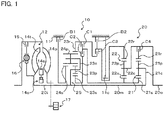
FIG. 1] FIG. 1 illustrates a schematic configuration of a power transfer device that includes a multi-speed transmission according to the present invention. - [
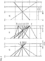
FIG. 2] FIG. 2 is a velocity diagram illustrating the ratio of the rotational speed of each rotary element to an input rotational speed of the multi-speed transmission according to the present invention. - [
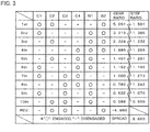
FIG. 3] FIG. 3 is an operation table illustrating the relationship between each shift speed of the multi-speed transmission according to the present invention and the respective operating states of clutches and brakes. - [
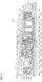
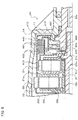
FIG. 4] FIG. 4 is a sectional view illustrating the multi-speed transmission according to the present invention. - [
FIG. 5] FIG. 5 is an enlarged sectional view illustrating the multi-speed transmission according to the present invention. - [
FIG. 6] FIG. 6 is an enlarged sectional view illustrating the multi-speed transmission according to the present invention. - Now, an embodiment of the present invention will be described with reference to the drawings.
-
FIG. 1 illustrates a schematic configuration of apower transfer device 10 that includes anautomatic transmission 20 that serves as a multi-speed transmission according to an embodiment of the present invention. Thepower transfer device 10 illustrated in the drawing is connected to a crankshaft of an engine (internal combustion engine; not illustrated) and/or a rotor of an electric motor that serves as a drive source vertically mounted in the front portion of a rear-drive vehicle, and can transfer power (torque) from the engine or the like to left and right rear wheels (drive wheels; not illustrated). As illustrated in the drawing, thepower transfer device 10 includes a transmission case (stationary member) 11, a starting device (fluid transmission apparatus) 12, an oil pump 17, and so forth in addition to theautomatic transmission 20 which transfers power, which has been transferred from the engine or the like to an input shaft 20i, to an output shaft 20o with the speed of the power changed. - The
starting device 12 includes a torque converter that has: apump impeller 14p on the input side coupled to the drive source discussed above; aturbine runner 14t on the output side coupled to the input shaft (input member) 20i of theautomatic transmission 20; astator 14s disposed on the inner side of thepump impeller 14p and theturbine runner 14t to rectify a flow of working oil from theturbine runner 14t to thepump impeller 14p; a one-way clutch 14o that is supported by a stator shaft (not illustrated) and that restricts the rotational direction of thestator 14s to one direction; and so forth. Further, thestarting device 12 includes: a lock-up clutch 15 that connects and disconnects a front cover coupled to the crankshaft of the engine or the like and the input shaft 20i of theautomatic transmission 20 to and from each other; and adamper mechanism 16 that damps vibration between the front cover and the input shaft 20i of theautomatic transmission 20. Thestarting device 12 may include a fluid coupling that does not have thestator 14s. - The oil pump 17 is constituted as a gear pump that has: a pump assembly that includes a pump body and a pump cover; an externally toothed gear (inner rotor) coupled to the
pump impeller 14p of thestarting device 12 via a chain or a gear train; an internally toothed gear (outer rotor) that meshes with the externally toothed gear; and so forth. The oil pump 17 is driven by power from the engine or the like to suction working oil (ATF) reserved in an oil pan (not illustrated) and pump the working oil to a hydraulic control device 60 (seeFIG. 4 ). - The
automatic transmission 20 is constituted as a 10-speed transmission. As illustrated inFIG. 1 , theautomatic transmission 20 includes, in addition to the input shaft 20i: the output shaft (output member) 20o which is coupled to the left and right rear wheels via a differential gear and a drive shaft (not illustrated); a firstplanetary gear 21 and a secondplanetary gear 22 of a single pinion type disposed side by side in the axial direction of the automatic transmission 20 (the input shaft 20i and the output shaft 20o); and a Ravigneaux typeplanetary gear mechanism 25 that serves as a composite planetary gear mechanism constituted by combining a double-pinion planetary gear and a single-pinion planetary gear with each other. Further, theautomatic transmission 20 includes a clutch C1 (first clutch) that serves as a first engagement element, a clutch C2 (second clutch) that serves as a second engagement element, a clutch C3 (third clutch) that serves as a third engagement element, a clutch C4 (fourth clutch) that serves as a fourth engagement element, a brake B1 (first brake) that serves as a fifth engagement element, and a brake B2 (second brake) that serves as a sixth engagement element, the clutches C1 to C4 and the brakes B1 and B2 being used to change a power transfer path from the input shaft 20i to the output shaft 20o. - In the embodiment, the first and second
planetary gears planetary gear mechanism 25 are disposed in thetransmission case 11 so as to be arranged in the order of the Ravigneaux typeplanetary gear mechanism 25, the secondplanetary gear 22, and the firstplanetary gear 21, that is, the single-pinion planetary gear which constitutes the Ravigneaux typeplanetary gear mechanism 25, the double-pinion planetary gear which constitutes the Ravigneaux typeplanetary gear mechanism 25, the secondplanetary gear 22, and the firstplanetary gear 21 from the side of thestarting device 12, that is, the side of the engine (left side inFIG. 1 ). Consequently, the Ravigneaux typeplanetary gear mechanism 25 is disposed on the side of the front portion of the vehicle in proximity to thestarting device 12. In addition, the firstplanetary gear 21 is disposed on the side of the rear portion of the vehicle in proximity to the output shaft 20o. Further, the secondplanetary gear 22 is disposed between the Ravigneaux typeplanetary gear mechanism 25 and the firstplanetary gear 21 in the axial direction of the input shaft 20i, the output shaft 20o, and so forth. - The first
planetary gear 21 has: afirst sun gear 21s which is an externally toothed gear; afirst ring gear 21r which is an internally toothed gear disposed concentrically with thefirst sun gear 21s; a plurality offirst pinion gears 21p that mesh with thefirst sun gear 21s and thefirst ring gear 21r; and afirst carrier 21c that rotatably and revolvably holds the plurality offirst pinion gears 21p. In the embodiment, a gear ratio λ1 of the first planetary gear 21 (the number of teeth of thefirst sun gear 21s/the number of teeth of thefirst ring gear 21r) is determined as λ1 = 0.277, for example. - As illustrated in
FIG. 1 , thefirst carrier 21c of the firstplanetary gear 21 is always coupled (fixed) to anintermediate shaft 20m of theautomatic transmission 20 which is coupled to the input shaft 20i. Consequently, when power is transferred from the engine or the like to the input shaft 20i, the power from the engine or the like is always transferred to thefirst carrier 21c via the input shaft 20i and theintermediate shaft 20m. Thefirst carrier 21c functions as an input element of the first planetary gear 21 (a first input element of the automatic transmission 20) when the clutch C4 is engaged, and idles when the clutch C4 is disengaged. In addition, thefirst ring gear 21r functions as an output element of the first planetary gear 21 (a first output element of the automatic transmission 20) when the clutch C4 is engaged. - The second
planetary gear 22 has: asecond sun gear 22s which is an externally toothed gear; asecond ring gear 22r which is an internally toothed gear disposed concentrically with thesecond sun gear 22s; a plurality ofsecond pinion gears 22p that mesh with thesecond sun gear 22s and thesecond ring gear 22r; and a second carrier (planetary carrier) 22c that rotatably and revolvably holds the plurality ofsecond pinion gears 22p. In the embodiment, a gear ratio λ2 of the second planetary gear 22 (the number of teeth of thesecond sun gear 22s/the number of teeth of thesecond ring gear 22r) is determined as λ2 = 0.244, for example. - As illustrated in
FIG. 1 , thesecond sun gear 22s of the secondplanetary gear 22 is integrated with (always coupled to) thefirst sun gear 21s of the firstplanetary gear 21, and rotated and stopped always together with (and coaxially with) thefirst sun gear 21s. It should be noted, however, that thefirst sun gear 21s and thesecond sun gear 22s may be constituted separately from each other and always coupled to each other via a coupling member (first coupling member; not illustrated). In addition, thesecond carrier 22c of the secondplanetary gear 22 is always coupled to the output shaft 20o, and rotated and stopped always together with (and coaxially with) the output shaft 20o. Consequently, thesecond carrier 22c functions as an output element of the second planetary gear 22 (a second output element of the automatic transmission 20). Further, thesecond ring gear 22r of the secondplanetary gear 22 functions as a fixable element of the second planetary gear 22 (a first fixable element of the automatic transmission 20). - The Ravigneaux type
planetary gear mechanism 25 has: athird sun gear 23s and afourth sun gear 24s which are each an externally toothed gear; athird ring gear 23r which is an internally toothed gear disposed concentrically with thethird sun gear 23s; a plurality of third pinion gears (short pinion gears) 23p that mesh with thethird sun gear 23s; a plurality of fourth pinion gears (long pinion gears) 24p that mesh with thefourth sun gear 24s and the plurality ofthird pinion gears 23p and mesh with thethird ring gear 23r; and athird carrier 23c that rotatably and revolvably holds the plurality ofthird pinion gears 23p and the plurality offourth pinion gears 24p. - The Ravigneaux type
planetary gear mechanism 25 is a composite planetary gear mechanism constituted by combining a double-pinion planetary gear (third planetary gear) and a single-pinion planetary gear (fourth planetary gear) with each other. That is, thethird sun gear 23s, thethird carrier 23c, the third and fourth pinion gears 23p and 24p, and thethird ring gear 23r of the Ravigneaux typeplanetary gear mechanism 25 constitute a double-pinion third planetary gear. In addition, thefourth sun gear 24s, thethird carrier 23c, the fourth pinion gears 24p, and thethird ring gear 23r of the Ravigneaux typeplanetary gear mechanism 25 constitute a single-pinion fourth planetary gear. In the embodiment, the Ravigneaux typeplanetary gear mechanism 25 is configured such that a gear ratio λ3 of the double-pinion third planetary gear (the number of teeth of thethird sun gear 23s/the number of teeth of thethird ring gear 23r) is determined as λ3 = 0.488, for example, and a gear ratio λ4 of the single-pinion fourth planetary gear (the number of teeth of thefourth sun gear 24s/the number of teeth of thethird ring gear 23r) is determined as λ4 = 0.581, for example. - In addition, among the rotary elements which constitute the Ravigneaux type planetary gear mechanism 25 (third and fourth planetary gears), the
fourth sun gear 24s functions as a fixable element of the Ravigneaux type planetary gear mechanism 25 (a second fixable element of the automatic transmission 20). Further, as illustrated inFIG. 1 , thethird carrier 23c is always coupled (fixed) to the input shaft 20i, and always coupled to thefirst carrier 21c of the firstplanetary gear 21 via theintermediate shaft 20m which serves as a coupling member (second coupling member). Consequently, when power is transferred from the engine or the like to the input shaft 20i, the power from the engine or the like is always transferred to thethird carrier 23c via the input shaft 20i. Thus, thethird carrier 23c functions as an input element of the Ravigneaux type planetary gear mechanism 25 (a second input element of the automatic transmission 20). In addition, thethird ring gear 23r functions as a first output element of the Ravigneaux typeplanetary gear mechanism 25, and thethird sun gear 23s functions as a second output element of the Ravigneaux typeplanetary gear mechanism 25. - The clutch C1 connects and disconnects the
first sun gear 21s of the firstplanetary gear 21 and thesecond sun gear 22s of the secondplanetary gear 22, which are always coupled to each other, and thethird ring gear 23r, which is the first output element of the Ravigneaux typeplanetary gear mechanism 25, to and from each other. The clutch C2 connects and disconnects thefirst sun gear 21s of the firstplanetary gear 21 and thesecond sun gear 22s of the secondplanetary gear 22, which are always coupled to each other, and thethird sun gear 23s, which is the second output element of the Ravigneaux typeplanetary gear mechanism 25, to and from each other. The clutch C3 connects and disconnects thesecond ring gear 22r of the secondplanetary gear 22 and thethird ring gear 23r, which is the first output element of the Ravigneaux typeplanetary gear mechanism 25, to and from each other. The clutch C4 connects and disconnects thefirst ring gear 21r, which is the output element of the firstplanetary gear 21, and the output shaft 20o to and from each other. - The brake B1 holds (connects) the
fourth sun gear 24s, which is a fixable element of the Ravigneaux typeplanetary gear mechanism 25, stationary to thetransmission case 11, which is a stationary member, such that thefourth sun gear 24s is unrotatable, and disconnects thefourth sun gear 24s from thetransmission case 11 such that thefourth sun gear 24s is rotatable. The brake B2 holds (connects) thesecond ring gear 22r, which is a fixable element of the secondplanetary gear 22, stationary to thetransmission case 11 such that thesecond ring gear 22r is unrotatable, and disconnects thesecond ring gear 22r from thetransmission case 11, which is a stationary member, such that thesecond ring gear 22r is rotatable. - In the embodiment, a multi-plate friction-type hydraulic clutch (friction engagement element) is adopted as the clutches C1 to C4. The multi-plate friction-type hydraulic clutch has a piston, a plurality of friction engagement plates (e.g. a friction plate constituted by affixing a friction material to both surfaces of an annular member, and a separator plate which is an annular member with both surfaces formed to be smooth), and a hydraulic servo constituted of an engagement oil chamber, a centrifugal hydraulic pressure cancellation chamber, etc. to which working oil is supplied. Meanwhile, a multi-plate friction-type hydraulic brake is adopted as the brakes B1 and B2. The multi-plate friction-type hydraulic brake has a piston, a plurality of friction engagement plates (a friction plate and a separator plate), and a hydraulic servo constituted of an engagement oil chamber etc. to which working oil is supplied. The clutches C1 to C4 and the brakes B1 and B2 operate with working oil supplied thereto and discharged therefrom by the hydraulic control device 60.
-
FIG. 2 is a velocity diagram illustrating the ratio of the rotational speed of each rotary element to the rotational speed of the input shaft 20i (input rotational speed) of the automatic transmission 20 (note that the rotational speed of the input shaft 20i, that is, thefirst carrier 21c and thethird carrier 23c, is defined as a value of 1). In addition,FIG. 3 is an operation table illustrating the relationship between each shift speed of theautomatic transmission 20 and the respective operating states of the clutches C1 to C4 and the brakes B1 and B2. - As illustrated in
FIG. 2 , the three rotary elements which constitute the single-pinion firstplanetary gear 21, that is, thefirst sun gear 21s, thefirst ring gear 21r, and thefirst carrier 21c, are arranged, on the velocity diagram for the first planetary gear 21 (the velocity diagram on the left side inFIG. 2 ), in the order of thefirst sun gear 21s, thefirst carrier 21c, and thefirst ring gear 21r from the left side of the drawing at intervals that match the gear ratio λ1. In the present invention, according to the order of arrangement on the velocity diagram, thefirst sun gear 21s is defined as the first rotary element of theautomatic transmission 20, thefirst carrier 21c is defined as the second rotary element of theautomatic transmission 20, and thefirst ring gear 21r is defined as the third rotary element of theautomatic transmission 20. Thus, the firstplanetary gear 21 has the first rotary element, the second rotary element, and the third rotary element of theautomatic transmission 20 which are arranged sequentially at intervals that match the gear ratio λ1 on the velocity diagram. - In addition, the three rotary elements which constitute the single-pinion second
planetary gear 22, that is, thesecond sun gear 22s, thesecond ring gear 22r, and thesecond carrier 22c, are arranged, on the velocity diagram for the second planetary gear 22 (the velocity diagram at the middle inFIG. 2 ), in the order of thesecond sun gear 22s, thesecond carrier 22c, and thesecond ring gear 22r from the left side of the drawing at intervals that match the gear ratio λ2. In the present invention, according to the order of arrangement on the velocity diagram, thesecond sun gear 22s is defined as the fourth rotary element of theautomatic transmission 20, thesecond carrier 22c is defined as the fifth rotary element of theautomatic transmission 20, and thesecond ring gear 22r is defined as the fourth rotary element of theautomatic transmission 20. Thus, the secondplanetary gear 22 has the fourth rotary element, the fifth rotary element, and the sixth rotary element of theautomatic transmission 20 which are arranged sequentially at intervals that match the gear ratio λ2 on the velocity diagram. - Further, the four rotary elements which constitute the Ravigneaux type
planetary gear mechanism 25, that is, thefourth sun gear 24s which serves as a fixable element, thethird carrier 23c which serves as the input element, thethird ring gear 23r which serves as the first output element, and thethird sun gear 23s which serves as the second output element, are arranged, on the velocity diagram for the Ravigneaux type planetary gear mechanism 25 (the velocity diagram on the right side inFIG. 2 ), in the order of thefourth sun gear 24s, thethird carrier 23c, thethird ring gear 23r, and thethird sun gear 23s from the left side of the drawing at intervals that match the gear ratio λ3 of the single-pinion third planetary gear and the gear ratio λ4 of the double-pinion fourth planetary gear. In the present invention, according to the order of arrangement on the velocity diagram, thefourth sun gear 24s is defined as the seventh rotary element of theautomatic transmission 20, thethird carrier 23c is defined as the eighth rotary element of theautomatic transmission 20, and thethird ring gear 23r is defined as the ninth rotary element of theautomatic transmission 20, and thethird sun gear 23s is defined as the tenth rotary element of theautomatic transmission 20. Thus, the Ravigneaux typeplanetary gear mechanism 25 has the seventh rotary element, the eighth rotary element, the ninth rotary element, and the tenth rotary element of theautomatic transmission 20 which are arranged sequentially at intervals that match the gear ratios λ3 and λ4 on the velocity diagram. - In the
automatic transmission 20, the clutches C1 to C4 and the brakes B1 and B2 are engaged and disengaged as illustrated inFIG. 3 to change the relationship of connection of the first to tenth rotary elements discussed above (note that the first rotary element and the fourth rotary element are always coupled to each other, and thus substantially a total of nine rotary elements), which makes it possible to provide ten power transfer paths in the forward rotational direction and one power transfer path in the reverse rotational direction from the input shaft 20i to the output shaft 20o, that is, first to tenth forward speeds and a reverse speed. - Specifically, the first forward speed is established by engaging the clutches C1 and C2 and the brake B2 and disengaging the remaining clutches C3 and C4 and brake B1. That is, to establish the first forward speed, the
first sun gear 21s of the firstplanetary gear 21 and thesecond sun gear 22s of the secondplanetary gear 22 and thethird ring gear 23r (first output element) of the Ravigneaux typeplanetary gear mechanism 25 are connected to each other by the clutch C1. In addition, thefirst sun gear 21s of the firstplanetary gear 21 and thesecond sun gear 22s of the secondplanetary gear 22 and thethird sun gear 23s (second output element) of the Ravigneaux typeplanetary gear mechanism 25 are connected to each other by the clutch C2. Further, thesecond ring gear 22r (fixable element) of the secondplanetary gear 22 is held stationary to thetransmission case 11 by the brake B2 so as to be unrotatable. In the embodiment (in the case where the gear ratios of the first and secondplanetary gears - The second forward speed is established by engaging the clutch C1 and the brakes B1 and B2 and disengaging the remaining clutches C2, C3, and C4. That is, to establish the second forward speed, the
first sun gear 21s of the firstplanetary gear 21 and thesecond sun gear 22s of the secondplanetary gear 22 and thethird ring gear 23r (first output element) of the Ravigneaux typeplanetary gear mechanism 25 are connected to each other by the clutch C1. In addition, thefourth sun gear 24s (fixable element) of the Ravigneaux typeplanetary gear mechanism 25 is held stationary to thetransmission case 11 by the brake B1 so as to be unrotatable. Further, thesecond ring gear 22r (fixable element) of the secondplanetary gear 22 is held stationary to thetransmission case 11 by the brake B2 so as to be unrotatable. In the embodiment, a gear ratio γ2 of the second forward speed is determined as γ2 = 3.219. In addition, the step ratio between the first forward speed and the second forward speed is determined as γ1/γ2 = 1.581. - The third forward speed is established by engaging the clutch C2 and the brakes B1 and B2 and disengaging the remaining clutches C1, C3, and C4. That is, to establish the third forward speed, the
first sun gear 21s of the firstplanetary gear 21 and thesecond sun gear 22s of the secondplanetary gear 22 and thethird sun gear 23s (second output element) of the Ravigneaux typeplanetary gear mechanism 25 are connected to each other by the clutch C2. In addition, thefourth sun gear 24s (fixable element) of the Ravigneaux typeplanetary gear mechanism 25 is held stationary to thetransmission case 11 by the brake B1 so as to be unrotatable. Further, thesecond ring gear 22r (fixable element) of the secondplanetary gear 22 is held stationary to thetransmission case 11 by the brake B2 so as to be unrotatable. In the embodiment, a gear ratio γ3 of the third forward speed is determined as γ3 = 2.324. In addition, the step ratio between the second forward speed and the third forward speed is determined as γ2/γ3 = 1.385. - The fourth forward speed is established by engaging the clutch C4 and the brakes B1 and B2 and disengaging the remaining clutches C1, C2, and C3. That is, to establish the first forward speed, the
first ring gear 21r (output element) of the firstplanetary gear 21 and the output shaft 20o are connected to each other by the clutch C4. In addition, thefourth sun gear 24s (fixable element) of the Ravigneaux typeplanetary gear mechanism 25 is held stationary to thetransmission case 11 by the brake B1 so as to be unrotatable. Further, thesecond ring gear 22r (fixable element) of the secondplanetary gear 22 is held stationary to thetransmission case 11 by the brake B2 so as to be unrotatable. In the embodiment, a gear ratio γ4 of the fourth forward speed is determined as γ4 = 1.886. In addition, the step ratio between the third forward speed and the fourth forward speed is determined as γ3/γ4 = 1.232. - The fifth forward speed is established by engaging the clutches C2 and C4 and the brake B1 and disengaging the remaining clutches C1 and C3 and brake B2. That is, to establish the fifth forward speed, the
first sun gear 21s of the firstplanetary gear 21 and thesecond sun gear 22s of the secondplanetary gear 22 and thethird sun gear 23s (second output element) of the Ravigneaux typeplanetary gear mechanism 25 are connected to each other by the clutch C2. In addition, thefirst ring gear 21r (output element) of the firstplanetary gear 21 and the output shaft 20o are connected to each other by the clutch C4. Further, thefourth sun gear 24s (fixable element) of the Ravigneaux typeplanetary gear mechanism 25 is held stationary to thetransmission case 11 by the brake B1 so as to be unrotatable. In the embodiment, a gear ratio γ5 of the fifth forward speed is determined as γ5 = 1.491. In addition, the step ratio between the fourth forward speed and the fifth forward speed is determined as γ4/γ5 = 1.265. - The sixth forward speed is established by engaging the clutches C1 and C4 and the brake B1 and disengaging the remaining clutches C2 and C3 and brake B2. That is, to establish the sixth forward speed, the
first sun gear 21s of the firstplanetary gear 21 and thesecond sun gear 22s of the secondplanetary gear 22 and thethird ring gear 23r (first output element) of the Ravigneaux typeplanetary gear mechanism 25 are connected to each other by the clutch C1. In addition, thefirst ring gear 21r (output element) of the firstplanetary gear 21 and the output shaft 20o are connected to each other by the clutch C4. Further, thefourth sun gear 24s (fixable element) of the Ravigneaux typeplanetary gear mechanism 25 is held stationary to thetransmission case 11 by the brake B1 so as to be unrotatable. In the embodiment, a gear ratio γ6 of the sixth forward speed is determined as γ6 = 1.192. In addition, the step ratio between the fifth forward speed and the sixth forward speed is determined as γ5/γ6 = 1.251. - The seventh forward speed is established by engaging the clutches C1, C3, and C4 and disengaging the remaining clutch C2 and brakes B1 and B2. That is, to establish the seventh forward speed, the
first sun gear 21s of the firstplanetary gear 21 and thesecond sun gear 22s of the secondplanetary gear 22 and thethird ring gear 23r (first output element) of the Ravigneaux typeplanetary gear mechanism 25 are connected to each other by the clutch C1. In addition, thesecond ring gear 22r of the secondplanetary gear 22 and thethird ring gear 23r (first output element) of the Ravigneaux typeplanetary gear mechanism 25 are connected to each other by the clutch C3. Further, thefirst ring gear 21r (output element) of the firstplanetary gear 21 and the output shaft 20o are connected to each other by the clutch C4. In the embodiment, a gear ratio γ7 of the seventh forward speed is determined as γ7 = 1.000. In addition, the step ratio between the sixth forward speed and the seventh forward speed is determined as γ6/γ7 = 1.192. - The eighth forward speed is established by engaging the clutches C3 and C4 and the brake B1 and disengaging the remaining clutches C1 and C2 and brake B2. That is, to establish the eighth forward speed, the
second ring gear 22r of the secondplanetary gear 22 and thethird ring gear 23r (first output element) of the Ravigneaux typeplanetary gear mechanism 25 are connected to each other by the clutch C3. In addition, thefirst ring gear 21r (output element) of the firstplanetary gear 21 and the output shaft 20o are connected to each other by the clutch C4. Further, thefourth sun gear 24s (fixable element) of the Ravigneaux typeplanetary gear mechanism 25 is held stationary to thetransmission case 11 by the brake B1 so as to be unrotatable. In the embodiment, a gear ratio γ8 of the eighth forward speed is determined as γ8 = 0.785. In addition, the step ratio between the seventh forward speed and the eighth forward speed is determined as γ7/γ8 = 1.273. - The ninth forward speed is established by engaging the clutches C1 and C3 and the brake B1 and disengaging the remaining clutches C2 and C4 and brake B2. That is, to establish the ninth forward speed, the
first sun gear 21s of the firstplanetary gear 21 and thesecond sun gear 22s of the secondplanetary gear 22 and thethird ring gear 23r (first output element) of the Ravigneaux typeplanetary gear mechanism 25 are connected to each other by the clutch C1. In addition, thesecond ring gear 22r of the secondplanetary gear 22 and thethird ring gear 23r (first output element) of the Ravigneaux typeplanetary gear mechanism 25 are connected to each other by the clutch C3. Further, thefourth sun gear 24s (fixable element) of the Ravigneaux typeplanetary gear mechanism 25 is held stationary to thetransmission case 11 by the brake B1 so as to be unrotatable. In the embodiment, a gear ratio γ9 of the ninth forward speed is determined as γ9 = 0.632. In addition, the step ratio between the eighth forward speed and the ninth forward speed is determined as γ8/γ9 = 1.242. - The tenth forward speed is established by engaging the clutches C2 and C3 and the brake B1 and disengaging the remaining clutches C1 and C4 and brake B2. That is, to establish the tenth forward speed, the
first sun gear 21s of the firstplanetary gear 21 and thesecond sun gear 22s of the secondplanetary gear 22 and thethird sun gear 23s (second output element) of the Ravigneaux typeplanetary gear mechanism 25 are connected to each other by the clutch C2. In addition, thesecond ring gear 22r of the secondplanetary gear 22 and thethird ring gear 23r (first output element) of the Ravigneaux typeplanetary gear mechanism 25 are connected to each other by the clutch C3. Further, thefourth sun gear 24s (fixable element) of the Ravigneaux typeplanetary gear mechanism 25 is held stationary to thetransmission case 11 by the brake B1 so as to be unrotatable. In the embodiment, a gear ratio γ10 of the tenth forward speed is determined as γ10 = 0.588. In addition, the step ratio between the ninth forward speed and the tenth forward speed is determined as γ9/γ10 = 1.076. The spread (gear ratio width = the gear ratio γ1 of the first forward speed as the lowest shift speed/the gear ratio γ10 of the tenth forward speed as the highest shift speed) of theautomatic transmission 20 is determined as γ1/γ10 = 8.660. - The reverse speed is established by engaging the clutches C2 and C3 and the brake B2 and disengaging the remaining clutches C1 and C4 and brake B1. That is, to establish the reverse speed, the
first sun gear 21s of the firstplanetary gear 21 and thesecond sun gear 22s of the secondplanetary gear 22 and thethird sun gear 23s (second output element) of the Ravigneaux typeplanetary gear mechanism 25 are connected to each other by the clutch C2. In addition, thesecond ring gear 22r of the secondplanetary gear 22 and thethird ring gear 23r (first output element) of the Ravigneaux typeplanetary gear mechanism 25 are connected to each other by the clutch C3. Further, thesecond ring gear 22r (fixable element) of the secondplanetary gear 22 is held stationary to thetransmission case 11 by the brake B2 so as to be unrotatable. In the embodiment, a gear ratio yrev of the reverse speed is determined as yrev = -4.860. In addition, the step ratio between the first forward speed and the reverse speed is determined as |γrev/γ1| = 0.955. - As discussed above, with the
automatic transmission 20, it is possible to provide the first to tenth forward speeds and the reverse speed by engaging and disengaging the clutches C1 to C4 and the brakes B1 and B2. As a result, with theautomatic transmission 20, the spread can be further increased (in the embodiment, to 8.660) to improve the fuel efficiency of the vehicle at a high vehicle speed, in particular, and the acceleration performance at each shift speed. Further, the step ratio can be optimized (prevented from becoming higher) to improve the shifting feeling. Thus, with theautomatic transmission 20, both the fuel efficiency and the drivability of the vehicle can be improved well. - In the
automatic transmission 20, in addition, each of the first forward speed to the tenth forward speed and the reverse speed can be established by engaging three of the six engagement elements, namely the clutches C1 to C4 and the brakes B1 and B2, and disengaging the remaining three engagement elements. Consequently, it is possible to reduce the number of engagement elements to be disengaged to establish a shift speed compared to a transmission in which a plurality of shift speeds are established by engaging two of six clutches and brakes and disengaging the remaining four engagement elements, for example. As a result, the power transfer efficiency of theautomatic transmission 20 can be further improved by reducing a drag loss due to slight contact between members in the engagement elements disengaged to establish a shift speed. - In the
automatic transmission 20, further, as with thethird carrier 23c (input element) of the Ravigneaux typeplanetary gear mechanism 25, thefirst carrier 21c (second rotary element) of the firstplanetary gear 21 is always coupled to the input shaft 20i via theintermediate shaft 20m. In addition, when each of the fourth forward speed to eighth forward speed is established, thefirst ring gear 21r (third rotary element) of the firstplanetary gear 21 is connected to the output shaft 20o (thesecond carrier 22c of the second planetary gear 22) by the clutch C4. Consequently, torque distribution to the clutch C4 can be reduced compared to a clutch that selectively connects between a first carrier (second rotary element) of a first planetary gear and an input shaft in a transmission according to the related art (seeFIGS. 2 and3 of United States Patent No.8,202,190 ) in which a first ring gear (third rotary element) of the first planetary gear is always coupled to an output shaft together with a second carrier (fifth rotary element) of a second planetary gear and the first carrier (second rotary element) is selectively connected to the input shaft, for example. - That is, in the
automatic transmission 20, thefirst carrier 21c of the firstplanetary gear 21 is used as the second rotary element which is always coupled to the input shaft 20i, and thefirst ring gear 21r of the firstplanetary gear 21 is used as the third rotary element which is selectively connected to the output shaft 20o by the clutch C4. Consequently, torque transferred via the clutch C4 being engaged can be reduced to 1/(1 + λ1) compared to the clutch of the transmission according to the related art described above which selectively connects between the first carrier and the input shaft. Thus, in theautomatic transmission 20, torque distribution to the clutch C4 can be reduced well, and the clutch C4 can be made compact in at least one of the axial direction and the radial direction. As a result, with theautomatic transmission 20, it is possible to improve both the power transfer efficiency and the drivability, and to suppress an increase in size of the entire device. - In addition, with the first and second
planetary gears automatic transmission 20 can be further improved by reducing a meshing loss between rotary elements of the first and secondplanetary gears planetary gear mechanism 25, which is a composite planetary gear train constituted by combining a double-pinion third planetary gear and a single-pinion fourth planetary gear with each other, as in theautomatic transmission 20 described above, it is possible to improve the ease of assembly while suppressing an increase in weight of the entire device by reducing the number of parts. - Subsequently, a specific configuration of the
automatic transmission 20 will be described in detail. -
FIG. 4 is a sectional view illustrating theautomatic transmission 20.FIGS. 5 and6 are each an enlarged sectional view illustrating theautomatic transmission 20. As illustrated inFIGS. 1 and4 , the brake B1, which holds (connects) thefourth sun gear 24s which is a fixable element of the Ravigneaux typeplanetary gear mechanism 25 stationary to thetransmission case 11 such that thefourth sun gear 24s is unrotatable, is disposed the closest to the starting device 12 (engine), among the four clutches C1 to C4 and the two brakes B1 and B2. That is, the brake B1 is disposed on the side opposite to the first and secondplanetary gears planetary gear mechanism 25, that is, on the side of the front portion of the vehicle (left side inFIG. 1 ) with respect to the Ravigneaux typeplanetary gear mechanism 25. - As illustrated in
FIGS. 4 and5 , the brake B1 includes: abrake hub 500 always coupled (fixed) to thefourth sun gear 24s; a plurality offriction plates 501; a plurality ofseparator plates 502 and backing plates disposed alternately with thefriction plates 501; apiston 540 that presses thefriction plates 501 and theseparator plates 502 into friction engagement with each other; and a plurality of return springs (coil springs) SP5 that urge thepiston 540 away from thefriction plates 501 and theseparator plates 502. - The plurality of friction plates 501 (the respective inner peripheral portions thereof) of the brake B1 are fitted with splines formed in the outer peripheral surface of the
brake hub 500. Consequently, thefriction plates 501 are supported by thebrake hub 500 so as to rotate together with thebrake hub 500 and be movable in the axial direction. In addition, the plurality of separator plates 502 (the respective outer peripheral portions thereof) of the brake B1 are fitted with spines formed in the inner peripheral surface of adrum portion 11d that extends in the axial direction of the input shaft 20i from an annular front support (a support portion on the front side) 11f fixed to thetransmission case 11 to constitute a part of the transmission case 11 (stationary member). Consequently, the plurality ofseparator plates 502 are supported by thefront support 11f so as to be unrotatable with respect to thetransmission case 11 and movable in the axial direction. Thepiston 540 is supported by thefront support 11f so as to be unrotatable with respect to thetransmission case 11 and movable in the axial direction, and defines anengagement oil chamber 550 of the brake B1 together with thefront support 11f. - The
engagement oil chamber 550 of the brake B1 is supplied with an engagement hydraulic pressure (working oil) for the brake B1 regulated by a hydraulic control device via an oil passage formed in the input shaft 20i and thefront support 11f. In addition, the plurality of return springs SP5 are disposed between thepiston 540 and an annularspring support member 570 at intervals in the circumferential direction, and face theengagement oil chamber 550. Thespring support member 570 is fixed to thefront support 11f using a snap ring so as to be positioned on the side opposite to theengagement oil chamber 550 with respect to thepiston 540. A single plate spring may be used as the return spring SP5 of the brake B1 in place of the plurality of coil springs. - As illustrated in
FIGS. 1 and4 , the clutch C1 is disposed between the secondplanetary gear 22 and the Ravigneaux typeplanetary gear mechanism 25 so as to be proximate to the Ravigneaux type planetary gear mechanism 25 (third planetary gear). In addition, the clutch C2 is disposed between the secondplanetary gear 22 and the Ravigneaux typeplanetary gear mechanism 25 so as to be at least partially surrounded by a constituent member of the clutch C1 and be proximate to the Ravigneaux type planetary gear mechanism 25 (third planetary gear). Further, the clutch C3 is disposed between the secondplanetary gear 22 and the Ravigneaux typeplanetary gear mechanism 25 so as to be proximate to the secondplanetary gear 22. In addition, the brake B2 is disposed between the secondplanetary gear 22 and the Ravigneaux typeplanetary gear mechanism 25 so as to surround at least a part of the clutch C3 and be proximate to the secondplanetary gear 22. - As discussed above, the clutches C1 and C2 have the
first sun gear 21s of the firstplanetary gear 21 and thesecond sun gear 22s of the secondplanetary gear 22 as common connection target elements. Therefore, as illustrated inFIGS. 4 and5 , the clutches C1 and C2 share adrum member 120 that is always coupled (fixed) to thefirst sun gear 21s and thesecond sun gear 22s of the secondplanetary gear 22 and that functions as a clutch hub of the clutch C1 and a clutch drum of the clutch C2. In addition, as discussed above, the clutches C1 and C3 have thethird ring gear 23r of the Ravigneaux typeplanetary gear mechanism 25 as a common connection target element. Therefore, the clutches C1 and C3 share a drum member 130 that is always coupled (fixed) to thethird ring gear 23r and that functions as a clutch drum of the clutch C1 and a clutch hub of the clutch C3. Further, as discussed above, the clutch C3 and the brake B2 have thesecond ring gear 22r of the secondplanetary gear 22 as a connection target element and a fixation target element, respectively. Therefore, the clutch C3 and the brake B2 share adrum member 360 that functions as a clutch drum of the clutch C3 and a brake hub of the brake B2. - The
drum member 120 includes: ahub portion 121 used by the clutch C1; a drum portion 122 used by the clutch C2; and acoupling portion 125 always coupled (fixed) to thefirst sun gear 21s of the firstplanetary gear 21 and thesecond sun gear 22s of the secondplanetary gear 22 which are connection target elements of the clutches C1 and C2. Thehub portion 121 has: a tubular portion 121a that has splines formed in the outer peripheral surface; and anannular flange portion 121b that extends radially inward from one end (left end inFIG. 5 ) of the tubular portion 121a. In the embodiment, the inner peripheral surface of the tubular portion 121a is formed in a recessed circular columnar surface that has no recesses or projections. Consequently, it is possible to secure the strength of thehub portion 121 without increasing the thickness of the tubular portion 121a. The length of theflange portion 121b in the radial direction is determined as desired in accordance with the torque capacity required for the clutches C1 and C2. - The drum portion 122 is formed in a bottomed cylindrical shape with an open end (left end in
FIG. 5 ), and has a cylindrical portion and an annular side wall portion that extends radially inward from one end (right end inFIG. 5 ) of the cylindrical portion. Splines are formed in the inner peripheral surface of the drum portion 122 (cylindrical portion). The outer peripheral surface of the drum portion 122 (cylindrical portion) is formed in a circular columnar surface that has no recesses or projections. Consequently, it is possible to secure the strength of the drum portion 122 without increasing the thickness of the drum portion 122. Thecoupling portion 125 has an elongated tubular portion and a flange portion that extends radially outward from one end (left end inFIG. 5 ) of the tubular portion, and is supported coaxially and rotatably by the input shaft 20i via a bush, a radial bearing, or the like. The tubular portion (the other end thereof) of thecoupling portion 125 is coupled to the first and second sun gears 21s and 22s via splines or the like. The flange portion of thecoupling portion 125 is strongly fixed to the inner peripheral portion of the drum portion 122 by welding or the like. Consequently, the drum portion 122 is always coupled to the first and second sun gears 21s and 22s via thecoupling portion 125. - As illustrated in
FIG. 5 , an end portion of the drum portion 122 on the opening side is press-fitted into theflange portion 121b (opening) of thehub portion 121, and the outer peripheral surface of the end portion of the drum portion 122 on the opening side and the inner peripheral surface of theflange portion 121b are strongly fixed to each other by welding. Consequently, thehub portion 121 is always coupled to the first and second sun gears 21s and 22s via the drum portion 122 and thecoupling portion 125. Theflange portion 121b, which is fixed to the outer periphery of the end portion of the drum portion 122 on the opening side functions as an annular rib. In addition, the inner peripheral surface of the tubular portion 121a of thehub portion 121 faces the outer peripheral surface of the drum portion 122 via a clearance that matches the dimension of theflange portion 121b in the radial direction. An annular space 121c (oil reservoir) is defined between the tubular portion 121a of thehub portion 121 and the drum portion 122. The space 121c opens on the side opposite to the end portion of the drum portion 122 on the opening side and theflange portion 121b. - The drum member 130 includes: a drum portion 131 used by the clutch C1; a
hub portion 133 used by the clutch C3; and anannular support portion 135. In the embodiment, the drum portion 131, thehub portion 133, and thesupport portion 135 are shaped integrally by casting an aluminum alloy or the like, for example. The drum portion 131 has: a cylindrical portion that has an opening-side end portion (left end portion inFIG. 5 ) always coupled (fixed) to thethird ring gear 23r of the Ravigneaux typeplanetary gear mechanism 25 which is the connection target element of the clutches C1 and C3; and an annular side wall portion that extends radially inward from one end (right end inFIG. 5 ) of the cylindrical portion. Splines are formed in the inner peripheral surface of the drum portion 131 (cylindrical portion). The outer peripheral surface of the drum portion 131 (cylindrical portion) is formed in a circular columnar surface that has no recesses or projections. Consequently, it is possible to secure the strength of the drum portion 131 without increasing the thickness of the drum portion 131. - The
hub portion 133 of the drum member 130 extends from the annular side wall portion of the drum portion 131 toward the side (right side inFIG. 5 ) opposite to the opening-side end portion of the drum portion 131 (cylindrical portion). In the embodiment, thehub portion 133 is formed in a tubular shape that has a smaller outside diameter than that of the drum portion 131. Splines are formed in the outer peripheral surface of thehub portion 133. The inner peripheral surface of thehub portion 133 is formed in a recessed circular columnar surface that has no recesses or projections. Consequently, it is possible to secure the strength of thehub portion 133 without increasing the thickness of thehub portion 133. In the embodiment, thesupport portion 135 extends radially inward from the inner peripheral surface of thehub portion 133, and the inner peripheral portion of thesupport portion 135 is supported coaxially and rotatably by the coupling portion 125 (the outer peripheral surface thereof) of thedrum member 120 via a bush, a radial bearing, or the like. Further, a thrust bearing is disposed between thesupport portion 135 of the drum member 130 and the flange portion of thecoupling portion 125 of thedrum member 120. - The
drum member 360 includes: adrum portion 361 formed in a bottomed cylindrical shape with an open end (left end inFIG. 5 ); and acoupling portion 365 always coupled (fixed) to a ring gear flange (coupling member) 220 that rotates together with thesecond ring gear 22r of the secondplanetary gear 22 which is the connection target element (fixation target element) of the clutch C3 and the brake B2. Thedrum portion 361 of thedrum member 360 has a cylindrical portion and an annular side wall portion that extends radially inward from one end (right end inFIG. 5 ) of the cylindrical portion. Splines are formed in the inner peripheral surface and the outer peripheral surface of the drum portion 361 (cylindrical portion). The outer peripheral portion of thecoupling portion 365 is strongly fixed to the inner peripheral portion of the drum portion 361 (annular side wall portion) by welding or the like. - As illustrated in
FIG. 5 , thecoupling portion 365 of thedrum member 360 has a tubular portion that extends in the axial direction of the automatic transmission 20 (the input shaft 20i and the output shaft 20o). The tubular portion of thecoupling portion 365 is rotatably supported (centered) by the input shaft 20i via a bush, thecoupling portion 125 of thedrum member 120, and a shaft portion of thesecond sun gear 22s. In addition, an annular center support (intermediate support portion) 11c is fixed to thetransmission case 11. Thecenter support 11c is positioned between the drum portion 361 (Ravigneaux type planetary gear mechanism 25) of thedrum member 360 and the secondplanetary gear 22 to constitute a part of the transmission case 11 (stationary member). As illustrated in the drawing, thecenter support 11c extends radially inward from the inner peripheral surface of thetransmission case 11, and includes a tubular inner peripheral portion that has a center hole. A sleeve made of iron is fixed to the inner peripheral surface of the inner peripheral portion. The sleeve suppresses wear of a bush (made of aluminum) due to slide of a seal member provided to the tubular portion of thecoupling portion 365. - In addition, the distal end portion of the tubular portion of the
coupling portion 365 is formed to have a smaller outside diameter than that of a portion surrounded by the inner peripheral surface of the inner peripheral portion of thecenter support 11c, and splines are formed in the outer peripheral surface of the distal end portion. Further, thering gear flange 220 has: an inner peripheral portion fitted (spline-fitted) with the splines at the distal end portion of the coupling portion 365 (tubular portion); and an outer peripheral portion fitted (spline-fitted) with the splines formed in the inner peripheral surface of thesecond ring gear 22r. Consequently, the drum member 360 (drum portion 361) is always coupled to thesecond ring gear 22r via the two fitting portions (spline-fitting portions) provided on the inner peripheral side and the outer peripheral side of thering gear flange 220. - In the embodiment, at least one of the fitting portion between the inner peripheral portion of the
ring gear flange 220 and thedrum member 360 and the fitting portion between the outer peripheral portion of thering gear flange 220 and thesecond ring gear 22r is constituted as a fitting portion with no centering function. Such a fitting portion with no centering function has larger play in the radial direction (a gap between the bottom land of the splines on thering gear flange 220 side and the top land of the splines of thecoupling portion 365 or thesecond ring gear 22r) than backlash in the circumferential direction between splines teeth that are adjacent to each other. In addition, as discussed above, the distal end portion of the coupling portion 365 (tubular portion) of thedrum member 360 has a smaller outside diameter than a portion supported by the inner peripheral surface of thecenter support 11c. Thus, the distal end portion of thecoupling portion 365 is fitted with the inner peripheral portion of thering gear flange 220 on the inner side (at a position proximate to theintermediate shaft 20m) with respect to the position at which the coupling portion 365 (tubular portion) is supported by thecenter support 11c. - The clutch C1, which includes the
drum members 120 and 130 discussed above as constituent members, includes, in addition to thedrum members 120 and 130: a plurality of friction plates (friction engagement plates) 101; a plurality of separator plates (friction engagement plates) 102 and backing plates disposed alternately with the friction plates 101; apiston 140 that presses the friction plates 101 and the separator plates 102 into friction engagement with each other; a plurality of return springs (coil springs) SP1 that urge thepiston 140 away from the friction plates 101 and the separator plates 102; and an annular cancel plate (cancellation oil chamber defining member) 170. - The plurality of friction plates 101 (the respective inner peripheral portions thereof) of the clutch C1 are fitted with splines formed in the outer peripheral surface of the
hub portion 121, that is, the tubular portion 121a, of thedrum member 120 which is disposed to be surrounded by the drum portion 131 of the drum member 130. Consequently, the plurality of friction plates 101 are supported by thedrum member 120 which functions as a clutch hub so as to rotate together with thehub portion 121 and be movable in the axial direction. In addition, the plurality of separator plates 102 (the respective outer peripheral portions thereof) of the clutch C1 are fitted with splines formed in the inner peripheral surface of the drum portion 131 of the drum member 130. Consequently, the plurality of separator plates 102 are supported by the drum member 130 which functions as a clutch drum so as to rotate together with the drum portion 131 and be movable in the axial direction. - The
piston 140 is disposed between the drum portion 131 of the drum member 130 and the drum portion 122 of thedrum member 120, and supported by thesupport portion 135 of the drum member 130 so as to rotate together with the drum member 130 and be movable in the axial direction. In addition, the cancelplate 170 is disposed between thepiston 140 and the drum portion 122 of thedrum member 120, that is, on the side opposite to thesupport portion 135 of the drum member 130 with respect to thepiston 140, and fixed to thesupport portion 135 using a snap ring. Thepiston 140 defines an engagement oil chamber (first engagement oil chamber) 150 of the clutch C1 together with thesupport portion 135 of the drum member 130. Further, the cancelplate 170 defines a centrifugal hydraulic pressure cancellation chamber (first centrifugal hydraulic pressure cancellation chamber) 190 for canceling a centrifugal hydraulic pressure generated in theengagement oil chamber 150 together with thepiston 140 and thesupport portion 135. - Consequently, all the oil chambers of the clutch C1, that is, the
engagement oil chamber 150 and the centrifugal hydraulicpressure cancellation chamber 190, are defined by the drum member 130 (support portion 135), thepiston 140, and the cancelplate 170, which rotate together with thethird ring gear 23r (first output element) of the Ravigneaux typeplanetary gear mechanism 25. In the embodiment, in addition, as illustrated inFIGS. 4 and5 , theengagement oil chamber 150 and the centrifugal hydraulicpressure cancellation chamber 190 of the clutch C1 are defined at a location away from the Ravigneaux typeplanetary gear mechanism 25 and in proximity to the secondplanetary gear 22 with respect to thehub portion 121 and the drum portion 122 of thedrum member 120. - The
engagement oil chamber 150 of the clutch C1 is supplied with an engagement hydraulic pressure (working oil) for the clutch C1 regulated by a hydraulic control device via an oil passage formed in the input shaft 20i, thecoupling portion 125 of thedrum member 120, thesupport portion 135 of the drum member 130, and so forth. In addition, the centrifugal hydraulicpressure cancellation chamber 190 is supplied with working oil (e.g. drain oil for lubrication and cooling) from a hydraulic control device via an oil passage formed in the input shaft 20i, thecoupling portion 125 of thedrum member 120, thesupport portion 135 of the drum member 130, and so forth. The plurality of return springs SP1 are disposed inside the centrifugal hydraulicpressure cancellation chamber 190 at intervals in the circumferential direction so as to be positioned between thepiston 140 and the cancelplate 170. A single leaf spring may be used as the return spring SP1 of the clutch C1 in place of the plurality of coil springs. - The clutch C2, which includes the
drum member 120 discussed above as a constituent member, includes, in addition to the drum member 120: aclutch hub 200; a plurality of friction plates (first friction engagement plates) 201; a plurality of separator plates 202 (second friction engagement plates) and backing plates; apiston 240 that presses thefriction plates 201 and theseparator plates 202 into friction engagement with each other; an annular oilchamber defining member 270; and a plurality of return springs (coil springs) SP2 that urge thepiston 240 away from thefriction plates 201 and theseparator plates 202. - The
clutch hub 200 has: a tubular portion that has splines formed in the outer peripheral surface; and an annular coupling portion that extends radially inward from the tubular portion and that is always coupled (fixed) to ashaft portion 230 that extends in the axial direction from thethird sun gear 23s of the Ravigneaux typeplanetary gear mechanism 25. The plurality of friction plates 201 (the respective outer peripheral portions thereof) of the clutch C2 are fitted with splines formed in the inner peripheral surface of the drum portion 122 of thedrum member 120 which is disposed to surround theclutch hub 200. Consequently, the plurality offriction plates 201 are supported by thedrum member 120 which functions as a clutch drum so as to rotate together with the drum portion 122 and be movable in the axial direction. In addition, the plurality of separator plates 202 (the respective inner peripheral portions thereof) of the clutch C2 are fitted with splines formed in the outer peripheral surface of the clutch hub 200 (tubular portion). Consequently, the plurality ofseparator plates 202 are supported by theclutch hub 200 so as to rotate together with theclutch hub 200 and be movable in the axial direction. - The
piston 240 is disposed so as to be surrounded by the drum portion 122 of thedrum member 120 and such that a part of thepiston 240 on the inner peripheral side is inserted inside the tubular portion of theclutch hub 200. Thepiston 240 is supported by theshaft portion 230 of thethird sun gear 23s so as to rotate together with theshaft portion 230 and be movable in the axial direction. In addition, the oilchamber defining member 270 is fixed to theshaft portion 230 using a snap ring so as to be positioned between thepiston 240 and thedrum member 120. That is, the oilchamber defining member 270 is positioned on the side opposite to the coupling portion of theclutch hub 200 and thethird sun gear 23s with respect to the piston 240 (the inner peripheral portion thereof). Thepiston 240 defines an engagement oil chamber (second engagement oil chamber) 250 of the clutch C2 together with the oilchamber defining member 270 and theshaft portion 230. Further, thepiston 240 defines a centrifugal hydraulic pressure cancellation chamber (second centrifugal hydraulic pressure cancellation chamber) 290 for canceling a centrifugal hydraulic pressure generated in theengagement oil chamber 250 together with theclutch hub 200 and theshaft portion 230. - Consequently, all the oil chambers of the clutch C2, that is, the
engagement oil chamber 250 and the centrifugal hydraulicpressure cancellation chamber 290, are defined by theshaft portion 230, thepiston 240, and the oilchamber defining member 270, which rotate together with thethird sun gear 23s (second output element) of the Ravigneaux typeplanetary gear mechanism 25. In the embodiment, in addition, as illustrated inFIGS. 4 and5 , theengagement oil chamber 250 and the centrifugal hydraulicpressure cancellation chamber 290 of the clutch C2 are defined at a location in proximity to the Ravigneaux typeplanetary gear mechanism 25 with respect to the cancelplate 170 of the clutch C1, that is, theengagement oil chamber 150 and the centrifugal hydraulicpressure cancellation chamber 190 of the clutch C1. Further, theengagement oil chamber 250 and the centrifugal hydraulicpressure cancellation chamber 290 are located away from the secondplanetary gear 22 and in proximity to the input shaft 20i. - The
engagement oil chamber 250 of the clutch C2 is supplied with an engagement hydraulic pressure (working oil) for the clutch C2 regulated by a hydraulic control device via an oil passage formed in the input shaft 20i, theshaft portion 230 of thethird sun gear 23s, and so forth. In addition, the centrifugal hydraulicpressure cancellation chamber 290 is supplied with working oil (e.g. drain oil for lubrication and cooling) from a hydraulic control device via an oil passage formed in the input shaft 20i, theshaft portion 230 of thethird sun gear 23s, and so forth. The plurality of return springs SP2 are disposed inside the centrifugal hydraulicpressure cancellation chamber 290 at intervals in the circumferential direction so as to be positioned between thepiston 240 and the clutch hub 200 (coupling portion). A single leaf spring may be used as the return spring SP2 of the clutch C2 in place of the plurality of coil springs. In the embodiment, further, theshaft portion 230 of thethird sun gear 23s, which serves as a hub member, and theclutch hub 200 are supported coaxially and rotatably by the input shaft 20i via a bush or a radial bearing, and supported in the axial direction by thethird carrier 23c of the Ravigneaux typeplanetary gear mechanism 25 and thecoupling portion 125 of thedrum member 120 via a thrust bearing. - The clutch C3, which includes the
drum members 130 and 360 discussed above as constituent members, includes, in addition to the drum members 130 and 360: a plurality offriction plates 301; a plurality ofseparator plates 302 and backing plates disposed alternately with thefriction plates 301; apiston 340 that presses thefriction plates 301 and theseparator plates 302 into friction engagement with each other; a plurality of return springs (coil springs) SP3 that urge thepiston 340 away from thefriction plates 301 and theseparator plates 302; and an annular cancel plate (cancellation oil chamber defining member) 370. - The plurality of friction plates 301 (the respective inner peripheral portions thereof) of the clutch C3 are fitted with splines formed in the outer peripheral surface of the
hub portion 133 of the drum member 130 which extends toward the secondplanetary gear 22, that is, toward the rear portion of the vehicle. Consequently, the plurality offriction plates 301 are supported by the drum member 130 which functions as a clutch hub so as to rotate together with thehub portion 133 and be movable in the axial direction. In addition, the plurality of separator plates 302 (the respective outer peripheral portions thereof) of the clutch C3 are fitted with splines formed in the inner peripheral surface of thedrum portion 361 of thedrum member 360 which is disposed to surround thehub portion 133 of the drum member 130. Consequently, the plurality ofseparator plates 302 are supported by thedrum member 360 which functions as a clutch drum so as to rotate together with thedrum portion 361 and be movable in the axial direction. - The
piston 340 is disposed between the drum member 130 and thedrum portion 361 of thedrum member 360, and supported by thecoupling portion 365 of thedrum member 360 so as to rotate together with thedrum member 360 and be movable in the axial direction. In addition, the cancelplate 370 is disposed between thepiston 340 and the drum member 130, that is, on the side opposite to thecoupling portion 365 of thedrum member 360 with respect to thepiston 340, and fixed to thecoupling portion 365 using a snap ring. Thepiston 340 defines an engagement oil chamber (third engagement oil chamber) 350 of the clutch C3 together with thedrum member 360. Further, the cancelplate 370 defines a centrifugal hydraulic pressure cancellation chamber (third centrifugal hydraulic pressure cancellation chamber) 390 for canceling a centrifugal hydraulic pressure generated in theengagement oil chamber 350 together with thepiston 340. - Consequently, all the oil chambers of the clutch C3, that is, the
engagement oil chamber 350 and the centrifugal hydraulicpressure cancellation chamber 390, are defined by thedrum member 360, thepiston 340, and the cancelplate 370, which rotate together with thesecond ring gear 22r of the secondplanetary gear 22. In the embodiment, in addition, as illustrated inFIG. 5 , theengagement oil chamber 350 and the centrifugal hydraulicpressure cancellation chamber 390 of the clutch C3 are defined at a location away from the Ravigneaux typeplanetary gear mechanism 25 and in proximity to the secondplanetary gear 22 with respect to thesupport portion 135 of the drum member 130, that is, theengagement oil chamber 150 and the centrifugal hydraulicpressure cancellation chamber 190 of the clutch C1. - The
engagement oil chamber 350 of the clutch C3 is supplied with an engagement hydraulic pressure (working oil) for the clutch C3 regulated by a hydraulic control device via an oil passage formed in thecenter support 11c, thecoupling portion 365 of thedrum member 360, and so forth. In addition, the centrifugal hydraulicpressure cancellation chamber 390 is supplied with working oil (e.g. drain oil for lubrication and cooling) from a hydraulic control device via an oil passage formed in theintermediate shaft 20m, thecoupling portion 125 of thedrum member 120, thecoupling portion 365 of thedrum member 360, and so forth. The plurality of return springs SP3 are disposed inside the centrifugal hydraulicpressure cancellation chamber 390 at intervals in the circumferential direction so as to be positioned between thepiston 340 and the cancelplate 370. A single leaf spring may be used as the return spring SP3 of the clutch C3 in place of the plurality of coil springs. - As illustrated in
FIGS. 4 and5 , the brake B2, which includes thedrum member 360 discussed above as a constituent member, includes: a plurality of friction plates 601; a plurality of separator plates 602 and backing plates disposed alternately with the friction plates 601; apiston 640 that presses the friction plates 601 and the separator plates 602 into friction engagement with each other; and a plurality of return springs (coil springs) SP6 that urge thepiston 640 away from the friction plates 601 and the separator plates 602. - The plurality of friction plates 601 (the respective inner peripheral portions thereof) of the brake B2 are fitted with splines formed in the outer peripheral surface of the
drum portion 361 of thedrum member 360. The friction plates 601 are supported by thedrum member 360 which functions as a brake hub so as to rotate together with thedrum portion 361 and be movable in the axial direction. In addition, the plurality of separator plates 602 (the respective outer peripheral portions thereof) of the brake B2 are fitted with splines formed in the inner peripheral surface of thetransmission case 11. The separator plates 602 are supported by thetransmission case 11 so as to be unrotatable with respect to thetransmission case 11 and movable in the axial direction. As illustrated inFIGS. 4 and5 , the friction plates 601 and the separator plates 602 of the brake B2 are disposed on the side opposite to the secondplanetary gear 22 with respect to thecenter support 11c, that is, on the Ravigneaux typeplanetary gear mechanism 25 side with respect to thecenter support 11c. Thepiston 640 is supported by thecenter support 11c discussed above so as to be unrotatable with respect to thetransmission case 11 and movable in the axial direction, and defines anengagement oil chamber 650 of the brake B2 together with thecenter support 11c. - The
engagement oil chamber 650 of the brake B2 is supplied with an engagement hydraulic pressure (working oil) for the brake B2 regulated by a hydraulic control device via an oil passage formed in thecenter support 11c. In addition, the plurality of return springs SP6 are disposed between thepiston 640 and an annularspring support member 670 at intervals in the circumferential direction, and face theengagement oil chamber 650. Thespring support member 670 is fixed to thecenter support 11c using a snap ring so as to be positioned on the side opposite to theengagement oil chamber 650 with respect to thepiston 640. A single leaf spring may be used as the return spring SP6 of the brake B2 in place of the plurality of coil springs. - As illustrated in
FIGS. 4 and6 , the clutch C4 is disposed the closest to the output shaft 20o, among the four clutches C1 to C4 and the two brakes B1 and B2. That is, the clutch C4 is disposed on the side opposite to the Ravigneaux typeplanetary gear mechanism 25 with respect to the secondplanetary gear 22, that is, on the side of the rear portion of the vehicle (right side inFIG. 1 ) with respect to the firstplanetary gear 21. As illustrated inFIG. 6 , the clutch C4 includes; aclutch hub 400; aclutch drum 410; a plurality offriction plates 401; a plurality ofseparator plates 402 and backing plates disposed alternately with thefriction plates 401; apiston 440 that presses thefriction plates 401 and theseparator plates 402 into friction engagement with each other; a plurality of return springs (coil springs) SP4 that urge thepiston 440 away from thefriction plates 401 and theseparator plates 402; and an annular cancel plate (cancellation oil chamber defining member) 470. - The
clutch hub 400 is rotatably supported by theintermediate shaft 20m via a bush or a radial bearing, and supported in the axial direction by a flange portion formed on theintermediate shaft 20m and the output shaft 20o via two thrust bearings disposed on the front and the rear. In addition, theclutch hub 400 is always coupled (fixed) to thefirst ring gear 21r of the firstplanetary gear 21 via splines and a snap ring. Theclutch drum 410 has: an annularside wall portion 411 fixed to an expanded diameter portion formed on the output shaft 20o by welding or the like; and acylindrical portion 412 formed in a bottomed cylindrical shape with an open end (left end inFIG. 6 ) and joined to the outer peripheral portion of the annularside wall portion 411 by welding or the like to extend along the axial direction of the output shaft 20o etc. An end portion (left end portion in FIG. 7) of thecylindrical portion 412 on the opening side is always coupled (fixed) to thesecond carrier 22c of the secondplanetary gear 22 via splines or the like. - The plurality of friction plates 401 (the respective inner peripheral portions thereof) of the clutch C4 are fitted with splines formed in the outer peripheral surface of the
clutch hub 400. Consequently, the plurality offriction plates 401 are supported by theclutch hub 400 so as to rotate together with theclutch hub 400 and be movable in the axial direction. In addition, the plurality ofseparator plates 402 of the clutch C4 are fitted with splines formed in the inner peripheral surface of thecylindrical portion 412 of theclutch drum 410. Consequently, the plurality of separator plates 402 (the respective outer peripheral portions thereof) are supported by theclutch drum 410 so as to rotate together with theclutch drum 410 and be movable in the axial direction. - The
piston 440 is disposed in thecylindrical portion 412 of theclutch drum 410 on the firstplanetary gear 21 side (on the side of the front portion of the vehicle) with respect to the annularside wall portion 411, and supported by the output shaft 20o so as to rotate together with the output shaft 20o and be movable in the axial direction. In addition, the cancelplate 470 is fixed to the output shaft 20o using a snap ring so as to be positioned on the firstplanetary gear 21 side (on the side of the front portion of the vehicle) with respect to thepiston 440. Thepiston 440 defines an engagement oil chamber (first engagement oil chamber) 450 of the clutch C4 together with theclutch drum 410, which serves as an oil chamber defining portion, and the output shaft 20o. Further, the cancelplate 170 defines a centrifugal hydraulic pressure cancellation chamber (fourth centrifugal hydraulic pressure cancellation chamber) 490 for canceling a centrifugal hydraulic pressure generated in theengagement oil chamber 450 together with thepiston 440 and the output shaft 20o. Consequently, all the oil chambers of the clutch C4, that is, theengagement oil chamber 450 and the centrifugal hydraulicpressure cancellation chamber 490, are defined by theclutch drum 410, thepiston 440, and the cancelplate 470, which rotate together with thesecond carrier 22c of the secondplanetary gear 22 and the output shaft 20o. - The
engagement oil chamber 450 of the clutch C4 is supplied with an engagement hydraulic pressure (working oil) for the clutch C4 regulated by a hydraulic control device via an oil passage formed in thetransmission case 11, the output shaft 20o, and so forth. In addition, the centrifugal hydraulicpressure cancellation chamber 490 is supplied with working oil (e.g. drain oil for lubrication and cooling) from a hydraulic control device via an oil passage formed in thetransmission case 11, the output shaft 20o, and so forth. The plurality of return springs SP4 are disposed inside the centrifugal hydraulicpressure cancellation chamber 490 at intervals in the circumferential direction so as to be positioned between thepiston 440 and the cancelplate 470. A single leaf spring may be used as the return spring SP4 of the clutch C4 in place of the plurality of coil springs. In addition, the output shaft 20o is rotatably supported by thetransmission case 11 via a bush, a radial bearing, or a thrust bearing. - In the
automatic transmission 20 configured as discussed above, the clutch C2 corresponds to thethird sun gear 23s (seeFIG. 2 ) which rotates at a higher speed, among of thethird ring gear 23r (first output element) and thethird sun gear 23s (second output element) of the Ravigneaux typeplanetary gear mechanism 25. The clutch C2 is disposed between the Ravigneaux typeplanetary gear mechanism 25 and the secondplanetary gear 22 which is disposed in proximity to the Ravigneaux typeplanetary gear mechanism 25 with respect to the firstplanetary gear 21. Thus, in theautomatic transmission 20, there is no need to configure the constituent members of the clutch C2 to bypass the first and secondplanetary gears engagement oil chamber 250 and the centrifugal hydraulicpressure cancellation chamber 290 of the clutch C2 are defined at a location in proximity to the input shaft 20i with respect to theengagement oil chamber 150 and the centrifugal hydraulicpressure cancellation chamber 190 of the clutch C1. - Consequently, an increase in size of the
automatic transmission 20 can be suppressed by suppressing an increase in dimensions (such as outside diameter, axial length, and thickness), that is, weight, due to securing the strength of the constituent members of the clutch C2 such as theshaft portion 230, thepiston 240, and the oilchamber defining member 270. In addition, it is possible to improve the speed change performance by reducing the inertia (equivalent inertia for the input shaft 20i) during rotation of thethird sun gear 23s, which rotates at a higher speed than that of thethird ring gear 23r, and theshaft portion 230, thepiston 240, and the oilchamber defining member 270, which rotate together with thethird sun gear 23s. Further, it is possible to further reduce the inertia during rotation of the members which rotate together with thethird sun gear 23s, which rotates at a higher speed than that of thethird ring gear 23r, by coupling theclutch hub 200, which can be made smaller in diameter than thedrum member 120 which serves as a clutch drum, to thethird sun gear 23s. - In the
automatic transmission 20, in addition, theengagement oil chamber 150 and the centrifugal hydraulicpressure cancellation chamber 190 of the clutch C1 and theengagement oil chamber 350 and the centrifugal hydraulicpressure cancellation chamber 390 of the clutch C3 are disposed between the clutch C2 (theengagement oil chamber 250 and the centrifugal hydraulic pressure cancellation chamber 290) and the secondplanetary gear 22, which is disposed in proximity to the Ravigneaux typeplanetary gear mechanism 25 with respect to the firstplanetary gear 21. Additionally, the clutch C4 is disposed on the side opposite to the Ravigneaux type planetary gear mechanism 25 (on the side of the rear portion of the vehicle) with respect to the secondplanetary gear 22, which is disposed in proximity to the Ravigneaux typeplanetary gear mechanism 25 with respect to the firstplanetary gear 21. Consequently, it is possible to provide the clutch C2, which corresponds to thethird sun gear 23s which rotates at a higher speed than that of thethird ring gear 23r, in proximity to the Ravigneaux typeplanetary gear mechanism 25. Thus, it is possible to reduce the axial length, that is, the weight, of the constituent members of the clutch C2 such as theshaft portion 230, thepiston 240, and the oilchamber defining member 270, which rotate together with thethird sun gear 23s. As a result, it is possible to further improve the speed change performance by reducing the inertia during rotation of theshaft portion 230, thepiston 240, the oilchamber defining member 270, etc., and to suppress an increase in axial length of theautomatic transmission 20. - In the
automatic transmission 20, further, the clutch C1 (such as the drum portion 131), which corresponds to thethird ring gear 23r (first output element) of the Ravigneaux typeplanetary gear mechanism 25, is disposed so as to surround generally the entire clutch C2, that is, the drum portion 122 of thedrum member 120, theclutch hub 200, thefriction plates 201, theseparator plates 202, the oilchamber defining member 270, and so forth. Consequently, it is possible to suppress an increase in axial length of theautomatic transmission 20 better. In theautomatic transmission 20, in addition, the brake B1 is disposed on the side opposite to the first and secondplanetary gears 21 and 22 (on the side of the front portion of the vehicle) with respect to the Ravigneaux typeplanetary gear mechanism 25. Further, the brake B2 (such as thedrum portion 361 of thedrum member 360, the friction plates 601, and the separator plates 602) is disposed between the clutch C2 and the secondplanetary gear 22, which is disposed in proximity to the Ravigneaux typeplanetary gear mechanism 25 with respect to the firstplanetary gear 21, so as to surround a part of the clutch C3, that is, thehub portion 133, thefriction plates 301, theseparator plates 302, the oilchamber defining member 270, and so forth. Consequently, it is possible to suppress an increase in axial length of theautomatic transmission 20 while securing a sufficient space for arrangement of the clutches C1, C2, and C3 between the Ravigneaux typeplanetary gear mechanism 25 and the secondplanetary gear 22, which is disposed in proximity to the Ravigneaux typeplanetary gear mechanism 25 with respect to the firstplanetary gear 21. - Subsequently, operation of the
automatic transmission 20 will be described. - In the
automatic transmission 20, when each of the second forward speed to the sixth forward speed and the eighth forward speed to the tenth forward speed is established, the brake B1 is engaged to hold thefourth sun gear 24s (fixable element) of the Ravigneaux typeplanetary gear mechanism 25 stationary such that thefourth sun gear 24s is unrotatable (seeFIG. 3 ). Consequently, power, which has been transferred from the input shaft 20i to thethird carrier 23c (input element), is transferred to thethird sun gear 23s and thethird ring gear 23r (seeFIG. 2 ) with the speed of the power increased by the Ravigneaux typeplanetary gear mechanism 25 such that the rotational speed of thethird sun gear 23s (second output element) is higher than the rotational speed of thethird ring gear 23r (first output element). Thus, during operation of theautomatic transmission 20, thethird ring gear 23r and thethird sun gear 23s of the Ravigneaux typeplanetary gear mechanism 25 rotate at a rotational speed that is equal to or more than that of thethird carrier 23c, that is, the input shaft 20i, except when the reverse speed is established. - In the light of this, in the
automatic transmission 20, as discussed above, theengagement oil chamber 150 and the centrifugal hydraulicpressure cancellation chamber 190 of the clutch C1, which corresponds to thethird ring gear 23r, are defined by the drum member 130 (support portion 135), thepiston 140, and the cancelplate 170, which rotate together with thethird ring gear 23r. In addition, theengagement oil chamber 250 and the centrifugal hydraulicpressure cancellation chamber 290 of the clutch C2, which corresponds to thethird sun gear 23s, are defined by theshaft portion 230, thepiston 240, and the oilchamber defining member 270, which rotate together with thethird sun gear 23s. Consequently, it is possible to prevent working oil that has once been supplied from flowing out of the centrifugal hydraulicpressure cancellation chambers pressure cancellation chambers automatic transmission 20. As a result, with theautomatic transmission 20, it is possible to secure a good speed change performance by smoothly engaging the clutches C1 and C2 which correspond to thethird ring gear 23r and thethird sun gear 23s, respectively, which are the output elements of the Ravigneaux typeplanetary gear mechanism 25. - In the
automatic transmission 20 described above, in addition, the clutch C1 has: the drum member 130 which functions as a clutch drum that rotates together with thethird ring gear 23r; thepiston 140 which defines theengagement oil chamber 150 together with thesupport portion 135 of the drum member 130; and the cancelplate 170 which is fixed to thesupport portion 135 of the drum member 130 to define the centrifugal hydraulicpressure cancellation chamber 190 together with thepiston 140. Further, the clutch C2 has: theclutch hub 200 which is always coupled to thethird sun gear 23s; thepiston 240 which defines the centrifugal hydraulicpressure cancellation chamber 290 together with theclutch hub 200; and the oilchamber defining member 270 which is fixed to theclutch hub 200 to define theengagement oil chamber 250 together with thepiston 240. Consequently, theengagement oil chamber 150 and the centrifugal hydraulicpressure cancellation chamber 190 of the clutch C1 can be defined by members that rotate together with thethird ring gear 23r (first output element), and theengagement oil chamber 250 and the centrifugal hydraulicpressure cancellation chamber 290 of the clutch C2 can be defined by members that rotate together with thethird sun gear 23s (second output element). - In the
automatic transmission 20 described above, as illustrated inFIG. 2 , the maximum rotational speed of the first and second sun gears 21s and 22s of the first and secondplanetary gears automatic transmission 20, that is, the first to fourth sun gears 21s to 24s, the first tothird ring gears 21r to 23r, and the first tothird carriers 21c to 23c, when the output shaft 20o rotates forward (rotates in the direction in which the vehicle travels forward). In the light of this, in theautomatic transmission 20, theengagement oil chamber 150 and the centrifugal hydraulicpressure cancellation chamber 190 of the clutch C1 are defined by members that rotate together with thethird ring gear 23r, the maximum rotational speed of which is lower than that of the first and second sun gears 21s and 22s, and theengagement oil chamber 250 and the centrifugal hydraulicpressure cancellation chamber 290 of the clutch C2 are defined by members that rotate together with thethird sun gear 23s, the maximum rotational speed of which is lower than that of the first and second sun gears 21s and 22s. Consequently, the number of constituent members of the clutches C1 and C2 that rotate together with the first and second sun gears 21s and 22s can be reduced. As a result, it is possible to further improve the speed change performance of theautomatic transmission 20 by reducing the inertia during rotation of constituent members of the clutches C1 and C2 that rotate together with the first and second sun gears 21s and 22s which rotate at a high speed, that is, thedrum member 120, thefriction plates 101 and 201, and so forth. In theautomatic transmission 20, further, theengagement oil chambers pressure cancellation chambers third ring gear 23r and thethird sun gear 23s, which rotate relatively stably, rather than providing the engagement oil chambers and the centrifugal hydraulic pressure cancellation chambers on the side of the first and second sun gears 21s and 22s, the rotational speed of which is fluctuated significantly in accordance with the shift speed. Consequently, the speed change performance can be improved by reducing fluctuations in centrifugal hydraulic pressure for each shift speed. - In addition, even if the first and second sun gears 21s and 22s, which are connection target elements of the clutches C1 and C2, rotate at a very high rotational speed, deformation of the
drum member 120, in particular expansion of an end portion, on the opening side, of the drum portion 122 which serves as a clutch drum of the clutch C2, can be suppressed well by configuring thedrum member 120, which is shared by the clutches C1 and C2, as discussed above. That is, thetubular hub portion 121, which serves as a clutch hub of the clutch C1, is fixed to the outer periphery of the end portion, on the opening side, of the drum portion 122 with an open end which serves as a clutch drum of the clutch C2. Consequently, it is possible to significantly improve the strength of thedrum member 120, in particular the end portion, on the opening side, of the drum portion 122 which serves as a clutch drum of the clutch C2. Thus, even if the rotational speed of thedrum member 120, that is, the first and second sun gears 21s and 22s, is increased, deformation of thedrum member 120, in particular expansion of the end portion on the drum portion 122 on the opening side can be suppressed well. - Further, the
hub portion 121 of thedrum member 120 includes: the tubular portion 121a which is fitted with the inner peripheral portion of the friction plates 101 of the clutch C1; and theannular flange portion 121b which extends radially inward from one end of the tubular portion 121a and which is fixed to the outer periphery of an end portion of the drum portion 122 on the opening side, and theflange portion 121b functions as an annular rib. Thus, the strength of an end portion of the drum portion 122 on the opening side, and hence theentire drum member 120, can be improved better. With the strength of thedrum member 120, that is, the drum portion 122 which serves as a clutch drum, improved, an increase in weight of the drum member 120 (drum portion 122) can be suppressed to reduce the inertia during rotation, which makes it possible to improve the speed change performance of theautomatic transmission 20. - In the
automatic transmission 20, in addition, the inner peripheral surface of the tubular portion 121a of thehub portion 121, which serves as a clutch hub of the clutch C1, and the outer peripheral surface of the drum portion 122, which serves as a clutch drum of the clutch C2, face each other via a clearance. Thus, the annular space 121c (oil reservoir) is defined between the tubular portion 121a and the drum portion 122. The space 121c opens on the side opposite to the end portion of the drum portion 122 on the opening side. Consequently, not only working oil that has passed through the inside, that is, thefriction plates 201 of the clutch C2 which are fitted with the drum portion 122 and theseparator plates 202 which are fitted with theclutch hub 200 of the clutch C2 but also working oil scattered around the drum member 120 (drum portion 122) can be received in the space 121c between thehub portion 121 and the drum portion 122. As a result, working oil that serves as a lubrication and cooling medium can be supplied from the space 121c to the friction plates 101 of the clutch C1 which are fitted with thehub portion 121 and the separator plates 102 of the clutch C1 which are fitted with the drum member 130. - Thus, in the
automatic transmission 20, deformation of thedrum member 120 which is shared by the clutches C1 and C2 as a clutch hub of one of the clutches C1 and C2 and a clutch drum of the other, that is, deformation of the drum portion 122 (a clutch drum of the clutch C2) which is disposed to be at least partially surrounded by a constituent member of the clutch C1, can be suppressed well. In addition, the friction plates 101, which are fitted with thehub portion 121 and disposed around the drum portion 122, and the separator plates 102, which are fitted with the drum member 130, can be lubricated and cooled well. It is possible to make theautomatic transmission 20 compact by applying the drum member 120 (the clutch hub and the clutch drum) discussed above to the clutches C1 and C2 which correspond to thethird ring gear 23r (first output element) and thethird sun gear 23s (second output element), respectively, of the Ravigneaux typeplanetary gear mechanism 25. - In the
automatic transmission 20 discussed above, at least one of the clutches C1 to C4 and the brakes B1 and B2 may be a meshing engagement element such as a dog clutch or a dog brake. For example, in theautomatic transmission 20, a dog brake may be adopted as the brake B2 which is engaged continuously to establish the first forward speed to the fourth forward speed and which is engaged to establish the reverse speed. In theautomatic transmission 20, in addition, the gear ratios λ1 to λ4 used in the first and secondplanetary gears planetary gear mechanism 25 are not limited to those described above. In the automatic transmission, further, at least one of the first and secondplanetary gears planetary gear mechanism 25 may be replaced with a composite planetary gear train such as a Simpson type or a CR-CR type, for example. In addition, theautomatic transmission 20 discussed above may be altered into a transmission to be mounted on a front-drive vehicle. - As has been described above, the present invention provides a multi-speed transmission that transfers power, which has been transferred from a motor of a vehicle to an input member, to an output member with a speed of the power changed, the multi-speed transmission including: a Ravigneaux type planetary gear mechanism that has an input element, a fixable element, a first output element, and a second output element; a first planetary gear that has a plurality of rotary elements; a second planetary gear that has a plurality of rotary elements and that is disposed in proximity to the Ravigneaux type planetary gear mechanism with respect to the first planetary gear; a first brake that connects the fixable element of the Ravigneaux type planetary gear mechanism to a stationary member to hold the fixable element stationary such that the fixable element is unrotatable, and that disconnects the fixable element and the stationary member from each other; a first clutch that connects between the first output element of the Ravigneaux type planetary gear mechanism and at least one of the rotary elements of the first and second planetary gears, and that disconnects the first output element and the rotary element of the first and second planetary gears from each other; and a second clutch that connects between the second output element of the Ravigneaux type planetary gear mechanism and at least one of the rotary elements of the first and second planetary gears, and that disconnects the second output element and the rotary element of the first and second planetary gears from each other, characterized in that: the Ravigneaux type planetary gear mechanism transfers the power, which has been transferred to the input element, to the first and second output elements with the speed of the power increased such that a rotational speed of the second output element is higher than a rotational speed of the first output element when the fixable element is held stationary by the first brake so as to be unrotatable; and the second clutch is disposed between the Ravigneaux type planetary gear mechanism and the second planetary gear in an axial direction of the input member.
- That is, the multi-speed transmission transfers power, which has been transferred from the motor to the input member, to the output member with the speed of the power changed, and includes the Ravigneaux type planetary gear mechanism which transfers the power, which has been transferred to the input element, to the first and second output elements with the speed of the power increased such that the rotational speed of the second output element is higher than the rotational speed of the first output element when the fixable element is held stationary by the brake so as to be unrotatable. Further, the multi-speed transmission includes the second clutch which connects between the second output element of the Ravigneaux type planetary gear mechanism and at least one of the rotary elements of the first and second planetary gears, and that disconnects the second output element and the rotary element of the first and second planetary gears from each other, and the second clutch is disposed between the Ravigneaux type planetary gear mechanism and the second planetary gear which is disposed in proximity to the Ravigneaux type planetary gear mechanism with respect to the first planetary gear.
- Thus, with the second clutch, which corresponds to the second output element of the Ravigneaux type planetary gear mechanism which rotates at a higher speed, disposed between the Ravigneaux type planetary gear mechanism and the second planetary gear which is disposed in proximity to the Ravigneaux type planetary gear mechanism, there is no need to configure the constituent members of the second clutch to bypass the planetary gears with a large diameter. Consequently, an increase in size of the multi-speed transmission can be suppressed by suppressing an increase in dimensions (such as outside diameter, axial length, and thickness), that is, weight, due to securing the strength of the constituent members of the second clutch. Further, it is possible to improve the speed change performance by reducing the inertia during rotation of the second output element, which rotates at a higher speed than that of the first output element, and members that rotate together with the second output element.
- The second clutch may have a clutch hub always coupled to the second output element of the Ravigneaux type planetary gear mechanism, and a clutch drum always coupled to one of the rotary elements of the second planetary gear; and the clutch hub and the clutch drum of the second clutch may be disposed between the Ravigneaux type planetary gear mechanism and the second planetary gear in the axial direction. With the multi-speed transmission device, there is no need to configure the clutch hub and the clutch drum of the second clutch to bypass the planetary gears with a large diameter. Thus, it is possible to suppress an increase in size of the multi-speed transmission by suppressing an increase in weight of the clutch hub and the clutch drum of the second clutch, and to reduce the inertia during rotation of the clutch hub and the clutch drum of the second clutch.
- The second clutch may further have first and second friction engagement plates; and an outer peripheral portion of the first friction engagement plate may be fitted with the clutch drum, and an inner peripheral portion of the second friction engagement plate may be fitted with the clutch hub. That is, by coupling the clutch hub, which can be made smaller in diameter than the clutch drum, to the second output element, which rotates at a higher speed than that of the first output element, it is possible to further reduce the inertia during rotation of the clutch hub.
- The first clutch may have a clutch drum always coupled to the first output element of the Ravigneaux type planetary gear mechanism, and a clutch hub always coupled to one of the rotary elements of the second planetary gear; and the clutch drum and the clutch hub of the first clutch may be disposed between the Ravigneaux type planetary gear mechanism and the second planetary gear in the axial direction. With the multi-speed transmission device, there is no need to configure the clutch drum and the clutch hub of the first clutch to bypass the planetary gears with a large diameter. Thus, it is possible to suppress an increase in size of the multi-speed transmission by suppressing an increase in weight of the clutch drum and the clutch hub of the first clutch, and to reduce the inertia during rotation of the clutch drum and the clutch hub of the first clutch.
- The clutch drum of the first clutch may be disposed so as to surround at least a part of the clutch hub and the clutch drum of the second clutch from a radially outer side. Consequently, it is possible to suppress an increase in axial length of the multi-speed transmission better.
- The multi-speed transmission may further include a drum member that includes a hub portion that functions as the clutch hub of the first clutch, and a drum portion that functions as the clutch drum of the second clutch; and one of the rotary elements to be connected to the first output element of the Ravigneaux type planetary gear mechanism by the first clutch and one of the rotary elements to be connected to the second output element of the Ravigneaux type planetary gear mechanism by the second clutch may be the same as each other.
- The Ravigneaux type planetary gear mechanism may have a short pinion gear, a long pinion gear that meshes with the short pinion gear, a carrier that rotatably supports the short pinion gear and the long pinion gear, a ring gear that meshes with the long pinion gear, a sun gear that meshes with the short pinion gear, and a sun gear that meshes with the long pinion gear; and the fixable element may be the sun gear which meshes with the long pinion gear, the input element may be the carrier, the first output element may be the ring gear, and the second output element may be the sun gear which meshes with the short pinion gear. Consequently, it is possible to make the rotational speed of the sun gear, which serves as the second output element, higher than that of the ring gear, which serves as the first output element, when the sun gear, which serves as a fixable element, is held stationary by the first brake so as to be unrotatable.
- The multi-speed transmission may further include a second brake that connects one of the rotary elements of the second planetary gear to the stationary member to hold the rotary element stationary such that the rotary element is unrotatable, and that disconnects the rotary element and the stationary member from each other; and the clutch drum of the second clutch may be coupled to one of the rotary elements of the second planetary gear through a radially inner side of the second brake.
- The multi-speed transmission may further include a third clutch and a fourth clutch; three of the first, second, third, and fourth clutches and the first and second brakes may be selectively engaged to establish a plurality of shift speeds; oil chambers of the first and third clutches may be disposed between the second clutch and the second planetary gear in the axial direction; and the fourth clutch may be disposed on a side opposite to the Ravigneaux type planetary gear mechanism with respect to the second planetary gear. Consequently, it is possible to provide the second clutch, which corresponds to the second output element which rotates at a higher speed than that of the first output element, in proximity to the Ravigneaux type planetary gear mechanism. As a result, it is possible to reduce the axial length, that is, the weight, of the constituent members of the second clutch, which rotate together with the second output element, which makes it possible to further improve the speed change performance by reducing the inertia during rotation of the constituent members of the second clutch. Additionally, it is possible to suppress an increase in axial length of the multi-speed transmission.
- The first planetary gear may have a first sun gear, a first carrier, and a first ring gear; the second planetary gear may have a second sun gear, a second carrier, and a second ring gear; the first sun gear of the first planetary gear and the second sun gear of the second planetary gear may be always coupled to each other; the first carrier of the first planetary gear may be always coupled to the input member and the input element of the Ravigneaux type planetary gear mechanism; the second carrier of the second planetary gear may be always coupled to the output member; the first clutch may connect between the first output element of the Ravigneaux type planetary gear mechanism and the first and second sun gears which are always coupled to each other, and disconnect the first output element and the first and second sun gears from each other; the second clutch may connect between the second output element of the Ravigneaux type planetary gear mechanism and the first and second sun gears which are always coupled to each other, and disconnect the second output element and the first and second sun gears from each other; the third clutch may connect between the first output element of the Ravigneaux type planetary gear mechanism and the second ring gear of the second planetary gear, and disconnect the first output element and the second ring gear from each other; the fourth clutch may connect between the first ring gear of the first planetary gear and the second carrier of the second planetary gear, and disconnect the first ring gear and the second carrier from each other; and the second brake may connect the second ring gear of the second planetary gear to the stationary member to hold the second ring gear stationary such that the second ring gear is unrotatable, and disconnect the second ring gear and the stationary member from each other.
- The multi-speed transmission according to such an aspect includes the Ravigneaux type planetary gear mechanism, the first and second planetary gears, the first to fourth clutches, and the first and second brakes. With the multi-speed transmission, the first to tenth forward speeds and the reverse speed can be established by selectively engaging three of the first to fourth clutches and the first and second brakes. As a result, with the multi-speed transmission, the power transfer efficiency, that is, the fuel efficiency and the acceleration performance of the vehicle, can be improved by further increasing the spread (gear ratio width = the gear ratio of the lowest shift speed/the gear ratio of the highest shift speed). Further, the step ratio (the gear ratio of a shift speed/the gear ratio of a certain shift speed one step higher) can be optimized (suppressed an increase) to improve the shifting feeling. Thus, with the multi-speed transmission, both the power transfer efficiency and the drivability can be improved well.
- With the multi-speed transmission, further, as with the input element of the Ravigneaux type planetary gear mechanism, the first carrier of the first planetary gear is always coupled to the input member, and the first ring gear of the first planetary gear is selectively connected to the output member (and the second carrier of the second planetary gear) by the fourth clutch. Consequently, torque distribution to the fourth clutch can be reduced compared to a clutch that selectively connects between a first carrier and an input member in a transmission in which a first ring gear of a first planetary gear is always coupled to an output member together with a second carrier of a second planetary gear and the first carrier of the first planetary gear is selectively connected to the input member. As a result, the fourth clutch can be made compact in at least one of the axial direction and the radial direction. Thus, with the multi-speed transmission, it is possible to improve both the power transfer efficiency and the drivability, and to suppress an increase in size of the entire device.
- With the multi-speed transmission, the first to tenth forward speeds and the reverse speed can be established by engaging the first to fourth clutches and the first and second brakes as follows. The first forward speed is established by engaging the first clutch, the second clutch, and the second brake. The second forward speed is established by engaging the first clutch, the first brake, and the second brake. The third forward speed is established by engaging the second clutch, the first brake, and the second brake. The fourth forward speed is established by engaging the fourth clutch, the first brake, and the second brake. The fifth forward speed is established by engaging the second clutch, the fourth clutch, and the first brake. The sixth forward speed is established by engaging the first clutch, the fourth clutch, and the first brake. The seventh forward speed is established by engaging the first clutch, the third clutch, and the fourth clutch. The eighth forward speed is established by engaging the third clutch, the fourth clutch, and the first brake. The ninth forward speed is established by engaging the first clutch, the third clutch, and the first brake. The tenth forward speed is established by engaging the second clutch, the third clutch, and the first brake. The reverse speed is established by engaging the second clutch, the third clutch, and the second brake.
- Consequently, with the multi-speed transmission according to the aspect described above, each of the first forward speed to the tenth forward speed and the reverse speed is established by engaging three of the first to fourth clutches and the first and second brakes and disengaging the remaining three first to fourth clutches and the first and second brakes. Consequently, it is possible to reduce the number of engagement elements to be disengaged to establish a shift speed compared to a transmission in which a plurality of shift speeds are established by engaging two of six engagement elements and disengaging the remaining four engagement elements, for example. As a result, the power transfer efficiency of the multi-speed transmission can be further improved by reducing a drag loss in the engagement elements disengaged to establish a shift speed.
- The output member may be an output shaft coupled to rear wheels of the vehicle via a differential gear. That is, the multi-speed transmission according to the present invention may be constituted as a transmission to be mounted on a rear-drive vehicle. It should be noted, however, that the multi-speed transmission according to the present invention may also be constituted as a transmission to be mounted on a front-drive vehicle as discussed above.
- The present invention is not limited to the embodiment described above in any way, and it is a matter of course that the present invention may be modified in various ways without departing from the scope of the present invention. Further, the mode for carrying out the present invention described above is merely a specific form of the invention described in the "SUMMARY OF THE INVENTION" section, and does not limit the elements of the invention described in the "SUMMARY OF THE INVENTION" section.
- The present invention can be utilized in the multi-speed transmission manufacturing industry etc.
Claims (12)
- A multi-speed transmission (20) that transfers power, which has been transferred from a motor of a vehicle to an input member (20i), to an output member (20o) with a speed changed, the multi-speed transmission (20) comprising:a Ravigneaux type planetary gear mechanism (25) that has an input element (23c), a fixable element (24s), a first output element (23r), and a second output element (23s), and the Ravigneaux type planetary gear mechanism (25) further having a short pinion gear (23p), a long pinion gear (24p) that meshes with the short pinion gear (23p), a carrier (23c) that rotatably supports the short pinion gear (23p) and the long pinion gear (24p), a ring gear (23r) that meshes with the long pinion gear (24p), a sun gear (23s) that meshes with the short pinion gear (23p), and a sun gear (24s) that meshes with the long pinion gear (24p);a first planetary gear (21) that has a plurality of rotary elements;a second planetary gear (22) that has a plurality of rotary elements and that is disposed in proximity to the Ravigneaux type planetary gear mechanism (25) with respect to the first planetary gear (21);a first brake (B1) that connects the fixable element (24s) of the Ravigneaux type planetary gear mechanism (25) to a stationary member (11) to hold the fixable element (24s) stationary such that the fixable element (24s) is unrotatable, and that disconnects the fixable element (24s) and the stationary member (11) from each other;a first clutch (CI) that connects between the first output element (23r) of the Ravigneaux type planetary gear mechanism (25) and at least one of the rotary elements of the second planetary gear (22), and that disconnects the first output element (23r) and the rotary element of the second planetary gear (22) from each other; anda second clutch (C2) that connects between the second output element (23s) of the Ravigneaux type planetary gear mechanism (25) and at least one of the rotary elements of the second planetary gear (22), and that disconnects the second output element (23s) and the rotary element of the second planetary gear (22) from each other, wherein:the Ravigneaux type planetary gear mechanism (25) transfers the power, which has been transferred to the input element (23c), to the first and second output elements (23r, 23s) with the speed increased such that a rotational speed of the second output element (23s) is higher than a rotational speed of the first output element (23r) when the fixable element (24s) is held stationary by the first brake (B1) so as to be unrotatable; andthe second clutch (C2) is disposed between the Ravigneaux type planetary gear mechanism (25) and the second planetary gear (22) in an axial direction of the input member (20i).
- The multi-speed transmission (20) according to claim 1, characterized in that:the second clutch (C2) has a clutch hub (200) always coupled to the second output element (23s) of the Ravigneaux type planetary gear mechanism (25), and a clutch drum (120) always coupled to one of the rotary elements of the second planetary gear (22); andthe clutch hub (200) and the clutch drum (120) of the second clutch (C2) are disposed between the Ravigneaux type planetary gear mechanism (25) and the second planetary gear (22) in the axial direction.
- The multi-speed transmission (20) according to claim 2, characterized in that:the second clutch (C2) further has first and second friction engagement plates (101, 102); andan outer peripheral portion of the first friction engagement plate (101) is fitted with the clutch drum (120), and an inner peripheral portion of the second friction engagement plate (102) is fitted with the clutch hub (200).
- The multi-speed transmission (20) according to claim 2 or 3, characterized in that:the first clutch (C1) has a clutch drum (130) always coupled to the first output element (23r) of the Ravigneaux type planetary gear mechanism (25), and a clutch hub (120) always coupled to one of the rotary elements of the second planetary gear (22); andthe clutch drum (130) and the clutch hub (120) of the first clutch (C1) are disposed between the Ravigneaux type planetary gear mechanism (25) and the second planetary gear (22) in the axial direction.
- The multi-speed transmission (20) according to claim 4, characterized in that
the clutch drum (130) of the first clutch (C1) is disposed so as to surround at least a part of the clutch hub (200) and the clutch drum (120) of the second clutch (C2) from a radially outer side. - The multi-speed transmission (20) according to claim 4 or 5, further comprising
a drum member (120) that includes a hub portion that functions as the clutch hub of the first clutch (C1), and a drum portion that functions as the clutch drum of the second clutch (C2), characterized in that
one of the rotary elements to be connected to the first output element (23r) of the Ravigneaux type planetary gear mechanism (25) by the first clutch (C1) and one of the rotary elements to be connected to the second output element (23s) of the Ravigneaux type planetary gear mechanism (25) by the second clutch (C2) are the same as each other. - The multi-speed transmission (20) according to any one of claims 2 to 6, characterized in that:
the fixable element is the sun gear (24s) which meshes with the long pinion gear (24p), the input element is the carrier (23c), the first output element is the ring gear (23r), and the second output element is the sun gear (23s) which meshes with the short pinion gear (23p). - The multi-speed transmission (20) according to any one of claims 2 to 7, further comprising
a second brake (B2) that connects one of the rotary elements of the second planetary gear (22) to the stationary member (11) to hold the rotary element stationary such that the rotary element is unrotatable, and that disconnects the rotary element and the stationary member (11) from each other, characterized in that
the clutch drum (120) of the second clutch (C2) is coupled to one of the rotary elements of the second planetary gear (22) through a radially inner side of the second brake (B2). - The multi-speed transmission (20) according to claim 8, further comprising
a third clutch (C3) and a fourth clutch (C4), characterized in that:three of the first, second, third, and fourth clutches (C1, C2, C3, C4) and the first and second brakes (B1, B2) are selectively engaged to establish a plurality of shift speeds;oil chambers of the first and third clutches (C1, C3) are disposed between the second clutch (C2) and the second planetary gear (22) in the axial direction; andthe fourth clutch (C4) is disposed on a side opposite to the Ravigneaux type planetary gear mechanism (25) with respect to the second planetary gear (22). - The multi-speed transmission (20) according to claim 9, characterized in that:the first planetary gear (21) has a first sun gear (21s), a first carrier (21c), and a first ring gear (21r);the second planetary gear (22) has a second sun gear (22s), a second carrier (22c), and a second ring gear (22r);the first sun gear (21s) of the first planetary gear (21) and the second sun gear (22s) of the second planetary gear (22) are always coupled to each other;the first carrier (21c) of the first planetary gear (21) is always coupled to the input member (20i) and the input element (23c) of the Ravigneaux type planetary gear mechanism (25);the second carrier (22c) of the second planetary gear (22) is always coupled to the output member (20o);the first clutch (C1) connects between the first output element (23r) of the Ravigneaux type planetary gear mechanism (25) and the first and second sun gears (21s, 22s) which are always coupled to each other, and disconnects the first output element (23r) and the first and second sun gears (21s, 22s) from each other;the second clutch (C2) connects between the second output element (23s) of the Ravigneaux type planetary gear mechanism (25) and the first and second sun gears (21s, 22s) which are always coupled to each other, and disconnects the second output element (23s) and the first and second sun gears (21s, 22s) from each other;the third clutch (C3) connects between the first output element (23r) of the Ravigneaux type planetary gear mechanism (25) and the second ring gear (22r) of the second planetary gear (22), and disconnects the first output element (23r) and the second ring gear (22r) from each other;the fourth clutch (C4) connects between the first ring gear (21r) of the first planetary gear (21) and the second carrier (22c) of the second planetary gear (22), and disconnects the first ring gear (21r) and the second carrier (22c) from each other; andthe second brake (B2) connects the second ring gear (22r) of the second planetary gear (22) to the stationary member (11) to hold the second ring gear (22r) stationary such that the second ring gear (22r) is unrotatable, and disconnects the second ring gear (22r) and the stationary member (11) from each other.
- The multi-speed transmission (20) according to claim 10, characterized in that:a first forward speed is established by engaging the first clutch (C1), the second clutch (C2), and the second brake (B2);a second forward speed is established by engaging the first clutch (C1), the first brake (B1), and the second brake (B2);a third forward speed is established by engaging the second clutch (C2), the first brake (B1), and the second brake (B2);a fourth forward speed is established by engaging the fourth clutch (C4), the first brake (B1), and the second brake (B2);a fifth forward speed is established by engaging the second clutch (C2), the fourth clutch (C4), and the first brake (B1);a sixth forward speed is established by engaging the first clutch (C1), the fourth clutch (C4), and the first brake (B1);a seventh forward speed is established by engaging the first clutch (C1), the third clutch (C3), and the fourth clutch (C4);an eighth forward speed is established by engaging the third clutch (C3), the fourth clutch (C4), and the first brake (B1);a ninth forward speed is established by engaging the first clutch (C1), the third clutch (C3), and the first brake (B1);a tenth forward speed is established by engaging the second clutch (C2), the third clutch (C3), and the first brake (B1); anda reverse speed is established by engaging the second clutch (C2), the third clutch (C3), and the second brake (B2).
- The multi-speed transmission (20) according to any one of claims 1 to 11, characterized in that
the output member (20o) is an output shaft coupled to rear wheels of the vehicle via a differential gear.
Applications Claiming Priority (2)
| Application Number | Priority Date | Filing Date | Title |
|---|---|---|---|
| JP2013248660A JP6191419B2 (en) | 2013-11-29 | 2013-11-29 | Multi-speed transmission |
| PCT/JP2014/081039 WO2015080076A1 (en) | 2013-11-29 | 2014-11-25 | Multistage transmission |
Publications (4)
| Publication Number | Publication Date |
|---|---|
| EP3034908A1 EP3034908A1 (en) | 2016-06-22 |
| EP3034908A4 EP3034908A4 (en) | 2016-11-30 |
| EP3034908B1 true EP3034908B1 (en) | 2018-06-13 |
| EP3034908B8 EP3034908B8 (en) | 2018-07-25 |
Family
ID=53199016
Family Applications (1)
| Application Number | Title | Priority Date | Filing Date |
|---|---|---|---|
| EP14865674.7A Not-in-force EP3034908B8 (en) | 2013-11-29 | 2014-11-25 | Multi-speed transmission |
Country Status (5)
| Country | Link |
|---|---|
| US (1) | US9739346B2 (en) |
| EP (1) | EP3034908B8 (en) |
| JP (1) | JP6191419B2 (en) |
| CN (1) | CN105683621B (en) |
| WO (1) | WO2015080076A1 (en) |
Families Citing this family (4)
| Publication number | Priority date | Publication date | Assignee | Title |
|---|---|---|---|---|
| US9689470B2 (en) * | 2014-03-21 | 2017-06-27 | GM Global Technology Operations LLC | Multi-speed transmission |
| JP6973965B2 (en) * | 2019-02-08 | 2021-12-01 | ジヤトコ株式会社 | Power transmission device |
| CN114286901A (en) * | 2019-11-27 | 2022-04-05 | 加特可株式会社 | Automatic transmission |
| CN113352870B (en) * | 2021-07-22 | 2022-06-24 | 中国北方车辆研究所 | Multi-mode oil-electric hybrid transmission device for hybrid electric vehicle |
Family Cites Families (23)
| Publication number | Priority date | Publication date | Assignee | Title |
|---|---|---|---|---|
| JP4051814B2 (en) | 1998-09-01 | 2008-02-27 | アイシン・エィ・ダブリュ株式会社 | Automatic transmission for vehicles |
| JP4081888B2 (en) | 1998-10-16 | 2008-04-30 | アイシン・エィ・ダブリュ株式会社 | Automatic transmission |
| US6428444B1 (en) | 1999-09-06 | 2002-08-06 | Toyota Jidosha Kabushiki Kaisha | Apparatus for controlling a vehicle and a method of controlling the vehicle |
| JP3890824B2 (en) | 1999-09-06 | 2007-03-07 | トヨタ自動車株式会社 | Vehicle control device |
| JP4016885B2 (en) * | 2003-05-27 | 2007-12-05 | トヨタ自動車株式会社 | Planetary gear type multi-stage transmission for vehicles |
| JP4492329B2 (en) * | 2004-12-07 | 2010-06-30 | アイシン・エィ・ダブリュ株式会社 | Automatic transmission |
| JP5194589B2 (en) | 2007-07-03 | 2013-05-08 | アイシン・エィ・ダブリュ株式会社 | Automatic transmission |
| US8202190B2 (en) * | 2007-08-24 | 2012-06-19 | GM Global Technology Operations LLC | Multi-speed transmission |
| DE102008055626A1 (en) * | 2008-11-03 | 2010-05-06 | Daimler Ag | gear unit |
| US8052566B2 (en) | 2009-02-16 | 2011-11-08 | GM Global Technology Operations LLC | Multi-speed transmissions |
| US8096915B2 (en) * | 2009-02-24 | 2012-01-17 | GM Global Technology Operations LLC | Multi-speed transmission |
| KR101028544B1 (en) * | 2009-06-30 | 2011-04-11 | 현대자동차주식회사 | Gear train of automatic transmission for vehicles |
| US8425368B2 (en) * | 2010-10-11 | 2013-04-23 | GM Global Technology Operations LLC | Transmission having at least ten speeds |
| US8529395B2 (en) * | 2011-01-06 | 2013-09-10 | GM Global Technology Operations LLC | Multi-speed transmission |
| US8197375B1 (en) * | 2011-04-27 | 2012-06-12 | GM Global Technology Operations LLC | Multi-speed transmission |
| KR101592368B1 (en) * | 2011-07-27 | 2016-02-11 | 현대자동차주식회사 | Planetary gear train of automatic transmission for vehicles |
| US8734285B2 (en) * | 2011-08-31 | 2014-05-27 | Gm Global Technology Operations | Transmission with dual clutch actuation assembly |
| JP6219145B2 (en) | 2013-08-30 | 2017-10-25 | アイシン・エィ・ダブリュ株式会社 | Multi-speed transmission |
| DE112014004521T5 (en) * | 2013-11-29 | 2016-06-16 | Aisin Aw Co., Ltd. | Power transmission device |
| DE112014004386T5 (en) * | 2013-11-29 | 2016-06-16 | Aisin Aw Co., Ltd. | Multi-stage transmission |
| JP6183187B2 (en) * | 2013-11-29 | 2017-08-23 | アイシン・エィ・ダブリュ株式会社 | Multi-speed transmission |
| JP6183207B2 (en) * | 2013-12-26 | 2017-08-23 | アイシン・エィ・ダブリュ株式会社 | Control device for automatic transmission |
| US9494217B2 (en) | 2014-03-20 | 2016-11-15 | Gm Global Technology Operations, Llc | Multi-speed transmission |
-
2013
- 2013-11-29 JP JP2013248660A patent/JP6191419B2/en not_active Expired - Fee Related
-
2014
- 2014-11-25 US US15/030,309 patent/US9739346B2/en not_active Expired - Fee Related
- 2014-11-25 WO PCT/JP2014/081039 patent/WO2015080076A1/en active Application Filing
- 2014-11-25 CN CN201480058501.3A patent/CN105683621B/en active Active
- 2014-11-25 EP EP14865674.7A patent/EP3034908B8/en not_active Not-in-force
Non-Patent Citations (1)
| Title |
|---|
| None * |
Also Published As
| Publication number | Publication date |
|---|---|
| CN105683621B (en) | 2018-05-15 |
| WO2015080076A1 (en) | 2015-06-04 |
| US20160245371A1 (en) | 2016-08-25 |
| EP3034908A4 (en) | 2016-11-30 |
| CN105683621A (en) | 2016-06-15 |
| US9739346B2 (en) | 2017-08-22 |
| JP2015105725A (en) | 2015-06-08 |
| JP6191419B2 (en) | 2017-09-06 |
| EP3034908A1 (en) | 2016-06-22 |
| EP3034908B8 (en) | 2018-07-25 |
Similar Documents
| Publication | Publication Date | Title |
|---|---|---|
| EP3045773B1 (en) | Multi-stage transmission | |
| JP6219145B2 (en) | Multi-speed transmission | |
| JP6232979B2 (en) | Transmission | |
| US20160341289A1 (en) | Multi-speed transmission | |
| JP6183467B2 (en) | Multi-speed transmission | |
| EP3034908B1 (en) | Multistage transmission | |
| JP6202101B2 (en) | Multi-speed transmission | |
| JP6418302B2 (en) | Transmission | |
| JP6377825B2 (en) | Multi-speed transmission | |
| JP6187352B2 (en) | Multi-speed transmission | |
| JP2016148363A (en) | Clutch and gear change device having the same | |
| JP2015105723A (en) | Multistage transmission | |
| JP2015052377A (en) | Frictional engagement device and transmission device with the same | |
| JP2015190495A (en) | Multistage transmission | |
| JP2015105724A (en) | Multistage transmission | |
| JP2017180524A (en) | Transmission |
Legal Events
| Date | Code | Title | Description |
|---|---|---|---|
| PUAI | Public reference made under article 153(3) epc to a published international application that has entered the european phase |
Free format text: ORIGINAL CODE: 0009012 |
|
| 17P | Request for examination filed |
Effective date: 20160317 |
|
| AK | Designated contracting states |
Kind code of ref document: A1 Designated state(s): AL AT BE BG CH CY CZ DE DK EE ES FI FR GB GR HR HU IE IS IT LI LT LU LV MC MK MT NL NO PL PT RO RS SE SI SK SM TR |
|
| AX | Request for extension of the european patent |
Extension state: BA ME |
|
| A4 | Supplementary search report drawn up and despatched |
Effective date: 20161031 |
|
| RIC1 | Information provided on ipc code assigned before grant |
Ipc: F16H 3/66 20060101AFI20161025BHEP |
|
| 17Q | First examination report despatched |
Effective date: 20161114 |
|
| DAX | Request for extension of the european patent (deleted) | ||
| GRAP | Despatch of communication of intention to grant a patent |
Free format text: ORIGINAL CODE: EPIDOSNIGR1 |
|
| INTG | Intention to grant announced |
Effective date: 20171201 |
|
| GRAS | Grant fee paid |
Free format text: ORIGINAL CODE: EPIDOSNIGR3 |
|
| GRAJ | Information related to disapproval of communication of intention to grant by the applicant or resumption of examination proceedings by the epo deleted |
Free format text: ORIGINAL CODE: EPIDOSDIGR1 |
|
| GRAL | Information related to payment of fee for publishing/printing deleted |
Free format text: ORIGINAL CODE: EPIDOSDIGR3 |
|
| GRAR | Information related to intention to grant a patent recorded |
Free format text: ORIGINAL CODE: EPIDOSNIGR71 |
|
| GRAA | (expected) grant |
Free format text: ORIGINAL CODE: 0009210 |
|
| INTC | Intention to grant announced (deleted) | ||
| GRAT | Correction requested after decision to grant or after decision to maintain patent in amended form |
Free format text: ORIGINAL CODE: EPIDOSNCDEC |
|
| AK | Designated contracting states |
Kind code of ref document: B1 Designated state(s): AL AT BE BG CH CY CZ DE DK EE ES FI FR GB GR HR HU IE IS IT LI LT LU LV MC MK MT NL NO PL PT RO RS SE SI SK SM TR |
|
| INTG | Intention to grant announced |
Effective date: 20180504 |
|
| REG | Reference to a national code |
Ref country code: GB Ref legal event code: FG4D |
|
| REG | Reference to a national code |
Ref country code: CH Ref legal event code: EP Ref country code: AT Ref legal event code: REF Ref document number: 1008827 Country of ref document: AT Kind code of ref document: T Effective date: 20180615 |
|
| RAP2 | Party data changed (patent owner data changed or rights of a patent transferred) |
Owner name: AISIN AW CO., LTD. |
|
| REG | Reference to a national code |
Ref country code: IE Ref legal event code: FG4D |
|
| REG | Reference to a national code |
Ref country code: DE Ref legal event code: R096 Ref document number: 602014027163 Country of ref document: DE |
|
| REG | Reference to a national code |
Ref country code: FR Ref legal event code: PLFP Year of fee payment: 5 |
|
| REG | Reference to a national code |
Ref country code: NL Ref legal event code: MP Effective date: 20180613 |
|
| REG | Reference to a national code |
Ref country code: LT Ref legal event code: MG4D |
|
| PG25 | Lapsed in a contracting state [announced via postgrant information from national office to epo] |
Ref country code: LT Free format text: LAPSE BECAUSE OF FAILURE TO SUBMIT A TRANSLATION OF THE DESCRIPTION OR TO PAY THE FEE WITHIN THE PRESCRIBED TIME-LIMIT Effective date: 20180613 Ref country code: CY Free format text: LAPSE BECAUSE OF FAILURE TO SUBMIT A TRANSLATION OF THE DESCRIPTION OR TO PAY THE FEE WITHIN THE PRESCRIBED TIME-LIMIT Effective date: 20180613 Ref country code: FI Free format text: LAPSE BECAUSE OF FAILURE TO SUBMIT A TRANSLATION OF THE DESCRIPTION OR TO PAY THE FEE WITHIN THE PRESCRIBED TIME-LIMIT Effective date: 20180613 Ref country code: NO Free format text: LAPSE BECAUSE OF FAILURE TO SUBMIT A TRANSLATION OF THE DESCRIPTION OR TO PAY THE FEE WITHIN THE PRESCRIBED TIME-LIMIT Effective date: 20180913 Ref country code: BG Free format text: LAPSE BECAUSE OF FAILURE TO SUBMIT A TRANSLATION OF THE DESCRIPTION OR TO PAY THE FEE WITHIN THE PRESCRIBED TIME-LIMIT Effective date: 20180913 Ref country code: ES Free format text: LAPSE BECAUSE OF FAILURE TO SUBMIT A TRANSLATION OF THE DESCRIPTION OR TO PAY THE FEE WITHIN THE PRESCRIBED TIME-LIMIT Effective date: 20180613 Ref country code: SE Free format text: LAPSE BECAUSE OF FAILURE TO SUBMIT A TRANSLATION OF THE DESCRIPTION OR TO PAY THE FEE WITHIN THE PRESCRIBED TIME-LIMIT Effective date: 20180613 |
|
| PG25 | Lapsed in a contracting state [announced via postgrant information from national office to epo] |
Ref country code: LV Free format text: LAPSE BECAUSE OF FAILURE TO SUBMIT A TRANSLATION OF THE DESCRIPTION OR TO PAY THE FEE WITHIN THE PRESCRIBED TIME-LIMIT Effective date: 20180613 Ref country code: HR Free format text: LAPSE BECAUSE OF FAILURE TO SUBMIT A TRANSLATION OF THE DESCRIPTION OR TO PAY THE FEE WITHIN THE PRESCRIBED TIME-LIMIT Effective date: 20180613 Ref country code: GR Free format text: LAPSE BECAUSE OF FAILURE TO SUBMIT A TRANSLATION OF THE DESCRIPTION OR TO PAY THE FEE WITHIN THE PRESCRIBED TIME-LIMIT Effective date: 20180914 Ref country code: RS Free format text: LAPSE BECAUSE OF FAILURE TO SUBMIT A TRANSLATION OF THE DESCRIPTION OR TO PAY THE FEE WITHIN THE PRESCRIBED TIME-LIMIT Effective date: 20180613 |
|
| REG | Reference to a national code |
Ref country code: AT Ref legal event code: MK05 Ref document number: 1008827 Country of ref document: AT Kind code of ref document: T Effective date: 20180613 |
|
| PG25 | Lapsed in a contracting state [announced via postgrant information from national office to epo] |
Ref country code: NL Free format text: LAPSE BECAUSE OF FAILURE TO SUBMIT A TRANSLATION OF THE DESCRIPTION OR TO PAY THE FEE WITHIN THE PRESCRIBED TIME-LIMIT Effective date: 20180613 |
|
| PG25 | Lapsed in a contracting state [announced via postgrant information from national office to epo] |
Ref country code: AT Free format text: LAPSE BECAUSE OF FAILURE TO SUBMIT A TRANSLATION OF THE DESCRIPTION OR TO PAY THE FEE WITHIN THE PRESCRIBED TIME-LIMIT Effective date: 20180613 Ref country code: PL Free format text: LAPSE BECAUSE OF FAILURE TO SUBMIT A TRANSLATION OF THE DESCRIPTION OR TO PAY THE FEE WITHIN THE PRESCRIBED TIME-LIMIT Effective date: 20180613 Ref country code: IS Free format text: LAPSE BECAUSE OF FAILURE TO SUBMIT A TRANSLATION OF THE DESCRIPTION OR TO PAY THE FEE WITHIN THE PRESCRIBED TIME-LIMIT Effective date: 20181013 Ref country code: EE Free format text: LAPSE BECAUSE OF FAILURE TO SUBMIT A TRANSLATION OF THE DESCRIPTION OR TO PAY THE FEE WITHIN THE PRESCRIBED TIME-LIMIT Effective date: 20180613 Ref country code: CZ Free format text: LAPSE BECAUSE OF FAILURE TO SUBMIT A TRANSLATION OF THE DESCRIPTION OR TO PAY THE FEE WITHIN THE PRESCRIBED TIME-LIMIT Effective date: 20180613 Ref country code: RO Free format text: LAPSE BECAUSE OF FAILURE TO SUBMIT A TRANSLATION OF THE DESCRIPTION OR TO PAY THE FEE WITHIN THE PRESCRIBED TIME-LIMIT Effective date: 20180613 Ref country code: SK Free format text: LAPSE BECAUSE OF FAILURE TO SUBMIT A TRANSLATION OF THE DESCRIPTION OR TO PAY THE FEE WITHIN THE PRESCRIBED TIME-LIMIT Effective date: 20180613 |
|
| PGFP | Annual fee paid to national office [announced via postgrant information from national office to epo] |
Ref country code: DE Payment date: 20181113 Year of fee payment: 5 |
|
| PG25 | Lapsed in a contracting state [announced via postgrant information from national office to epo] |
Ref country code: SM Free format text: LAPSE BECAUSE OF FAILURE TO SUBMIT A TRANSLATION OF THE DESCRIPTION OR TO PAY THE FEE WITHIN THE PRESCRIBED TIME-LIMIT Effective date: 20180613 Ref country code: IT Free format text: LAPSE BECAUSE OF FAILURE TO SUBMIT A TRANSLATION OF THE DESCRIPTION OR TO PAY THE FEE WITHIN THE PRESCRIBED TIME-LIMIT Effective date: 20180613 |
|
| PGFP | Annual fee paid to national office [announced via postgrant information from national office to epo] |
Ref country code: GB Payment date: 20181121 Year of fee payment: 5 Ref country code: FR Payment date: 20181011 Year of fee payment: 5 |
|
| REG | Reference to a national code |
Ref country code: DE Ref legal event code: R097 Ref document number: 602014027163 Country of ref document: DE |
|
| PLBE | No opposition filed within time limit |
Free format text: ORIGINAL CODE: 0009261 |
|
| STAA | Information on the status of an ep patent application or granted ep patent |
Free format text: STATUS: NO OPPOSITION FILED WITHIN TIME LIMIT |
|
| 26N | No opposition filed |
Effective date: 20190314 |
|
| PG25 | Lapsed in a contracting state [announced via postgrant information from national office to epo] |
Ref country code: SI Free format text: LAPSE BECAUSE OF FAILURE TO SUBMIT A TRANSLATION OF THE DESCRIPTION OR TO PAY THE FEE WITHIN THE PRESCRIBED TIME-LIMIT Effective date: 20180613 Ref country code: DK Free format text: LAPSE BECAUSE OF FAILURE TO SUBMIT A TRANSLATION OF THE DESCRIPTION OR TO PAY THE FEE WITHIN THE PRESCRIBED TIME-LIMIT Effective date: 20180613 |
|
| REG | Reference to a national code |
Ref country code: CH Ref legal event code: PL |
|
| PG25 | Lapsed in a contracting state [announced via postgrant information from national office to epo] |
Ref country code: MC Free format text: LAPSE BECAUSE OF FAILURE TO SUBMIT A TRANSLATION OF THE DESCRIPTION OR TO PAY THE FEE WITHIN THE PRESCRIBED TIME-LIMIT Effective date: 20180613 Ref country code: LU Free format text: LAPSE BECAUSE OF NON-PAYMENT OF DUE FEES Effective date: 20181125 |
|
| REG | Reference to a national code |
Ref country code: BE Ref legal event code: MM Effective date: 20181130 |
|
| REG | Reference to a national code |
Ref country code: IE Ref legal event code: MM4A |
|
| PG25 | Lapsed in a contracting state [announced via postgrant information from national office to epo] |
Ref country code: LI Free format text: LAPSE BECAUSE OF NON-PAYMENT OF DUE FEES Effective date: 20181130 Ref country code: CH Free format text: LAPSE BECAUSE OF NON-PAYMENT OF DUE FEES Effective date: 20181130 |
|
| PG25 | Lapsed in a contracting state [announced via postgrant information from national office to epo] |
Ref country code: IE Free format text: LAPSE BECAUSE OF NON-PAYMENT OF DUE FEES Effective date: 20181125 |
|
| PG25 | Lapsed in a contracting state [announced via postgrant information from national office to epo] |
Ref country code: BE Free format text: LAPSE BECAUSE OF NON-PAYMENT OF DUE FEES Effective date: 20181130 Ref country code: AL Free format text: LAPSE BECAUSE OF FAILURE TO SUBMIT A TRANSLATION OF THE DESCRIPTION OR TO PAY THE FEE WITHIN THE PRESCRIBED TIME-LIMIT Effective date: 20180613 |
|
| PG25 | Lapsed in a contracting state [announced via postgrant information from national office to epo] |
Ref country code: MT Free format text: LAPSE BECAUSE OF NON-PAYMENT OF DUE FEES Effective date: 20181125 |
|
| PG25 | Lapsed in a contracting state [announced via postgrant information from national office to epo] |
Ref country code: TR Free format text: LAPSE BECAUSE OF FAILURE TO SUBMIT A TRANSLATION OF THE DESCRIPTION OR TO PAY THE FEE WITHIN THE PRESCRIBED TIME-LIMIT Effective date: 20180613 |
|
| PG25 | Lapsed in a contracting state [announced via postgrant information from national office to epo] |
Ref country code: PT Free format text: LAPSE BECAUSE OF FAILURE TO SUBMIT A TRANSLATION OF THE DESCRIPTION OR TO PAY THE FEE WITHIN THE PRESCRIBED TIME-LIMIT Effective date: 20180613 |
|
| REG | Reference to a national code |
Ref country code: DE Ref legal event code: R119 Ref document number: 602014027163 Country of ref document: DE |
|
| PG25 | Lapsed in a contracting state [announced via postgrant information from national office to epo] |
Ref country code: MK Free format text: LAPSE BECAUSE OF NON-PAYMENT OF DUE FEES Effective date: 20180613 Ref country code: HU Free format text: LAPSE BECAUSE OF FAILURE TO SUBMIT A TRANSLATION OF THE DESCRIPTION OR TO PAY THE FEE WITHIN THE PRESCRIBED TIME-LIMIT; INVALID AB INITIO Effective date: 20141125 |
|
| GBPC | Gb: european patent ceased through non-payment of renewal fee |
Effective date: 20191125 |
|
| PG25 | Lapsed in a contracting state [announced via postgrant information from national office to epo] |
Ref country code: GB Free format text: LAPSE BECAUSE OF NON-PAYMENT OF DUE FEES Effective date: 20191125 Ref country code: DE Free format text: LAPSE BECAUSE OF NON-PAYMENT OF DUE FEES Effective date: 20200603 Ref country code: FR Free format text: LAPSE BECAUSE OF NON-PAYMENT OF DUE FEES Effective date: 20191130 |