EP3034888A1 - Blower - Google Patents
Blower Download PDFInfo
- Publication number
- EP3034888A1 EP3034888A1 EP14871395.1A EP14871395A EP3034888A1 EP 3034888 A1 EP3034888 A1 EP 3034888A1 EP 14871395 A EP14871395 A EP 14871395A EP 3034888 A1 EP3034888 A1 EP 3034888A1
- Authority
- EP
- European Patent Office
- Prior art keywords
- mouth
- bellmouth
- fan
- blower
- mouths
- Prior art date
- Legal status (The legal status is an assumption and is not a legal conclusion. Google has not performed a legal analysis and makes no representation as to the accuracy of the status listed.)
- Withdrawn
Links
Images



Classifications
-
- F—MECHANICAL ENGINEERING; LIGHTING; HEATING; WEAPONS; BLASTING
- F04—POSITIVE - DISPLACEMENT MACHINES FOR LIQUIDS; PUMPS FOR LIQUIDS OR ELASTIC FLUIDS
- F04D—NON-POSITIVE-DISPLACEMENT PUMPS
- F04D25/00—Pumping installations or systems
- F04D25/16—Combinations of two or more pumps ; Producing two or more separate gas flows
- F04D25/166—Combinations of two or more pumps ; Producing two or more separate gas flows using fans
-
- F—MECHANICAL ENGINEERING; LIGHTING; HEATING; WEAPONS; BLASTING
- F04—POSITIVE - DISPLACEMENT MACHINES FOR LIQUIDS; PUMPS FOR LIQUIDS OR ELASTIC FLUIDS
- F04D—NON-POSITIVE-DISPLACEMENT PUMPS
- F04D29/00—Details, component parts, or accessories
- F04D29/40—Casings; Connections of working fluid
- F04D29/52—Casings; Connections of working fluid for axial pumps
- F04D29/54—Fluid-guiding means, e.g. diffusers
- F04D29/541—Specially adapted for elastic fluid pumps
- F04D29/545—Ducts
-
- F—MECHANICAL ENGINEERING; LIGHTING; HEATING; WEAPONS; BLASTING
- F05—INDEXING SCHEMES RELATING TO ENGINES OR PUMPS IN VARIOUS SUBCLASSES OF CLASSES F01-F04
- F05D—INDEXING SCHEME FOR ASPECTS RELATING TO NON-POSITIVE-DISPLACEMENT MACHINES OR ENGINES, GAS-TURBINES OR JET-PROPULSION PLANTS
- F05D2250/00—Geometry
- F05D2250/50—Inlet or outlet
- F05D2250/52—Outlet
Definitions
- the present invention relates to a blower and particularly, to a blower which is provided with a bellmouth made of resin.
- An air conditioner has an indoor unit which performs heat exchange with indoor air, and an outdoor unit which dissipates heat to the outside air or absorbs heat from the outside air and is provided with a blower.
- the blower is provided with a fan, and a bellmouth for surrounding the fan and blowing air.
- the bellmouth is installed with a constant clearance provided between itself and the fan. The smaller the clearance, the higher the blowing effect of the bellmouth becomes, and therefore, in general, the clearance is set to be small.
- a projection opening (hereinafter referred to as a mouth) configuring the bellmouth is provided to correspond to the number of fans.
- a mouth For example, in an outdoor unit of PTL 1, two mouths are provided with a distance provided therebetween with respect to two fans arranged side by side in a vertical direction.
- a bellmouth made of metal or a bellmouth made of resin is used.
- a bellmouth made of metal has high rigidity, and therefore, a concern that the bellmouth may be deformed by an external force such as a snow load or a wind load is low.
- an external force such as a snow load or a wind load
- a bellmouth made of resin can be formed by, for example, injection molding, and therefore, the degree of freedom of a shape becomes higher.
- rigidity is low, compared to a bellmouth made of metal, and therefore, there is a concern that the bellmouth may be bent and deformed by an external force.
- the present invention has been made based on such a problem and has an object to provide a blower in which when a bellmouth made of resin, in which two mouths are arranged side by side, is subjected to an external force, the displacement of the mouths is suppressed.
- a blower including: a first fan; a second fan which is provided in parallel to the first fan; and a bellmouth which has a first mouth surrounding the first fan, and a second mouth surrounding the second fan, and is made of a resin material, wherein if the bellmouth is displaced by being subjected to an external force, a portion of the first mouth and a portion of the second mouth come into contact with each other.
- a portion of the first mouth and a portion of the second mouth face each other, and when the bellmouth is displaced, these sites come into contact with each other, whereby forces which are applied to the sites can cancel each other out. In this way, it is possible to suppress the displacement of the first mouth and the second mouth. Then, the clearances (the first clearance and the second clearance described above) between the first fan and the first mouth and between the second fan and the second mouth can be maintained, and therefore, a decrease in the performance of the blower or breakage of the bellmouth and/or the fans can be prevented.
- the first mouth has a first flat portion
- the second mouth has a second flat portion, and if the bellmouth is displaced by being subjected to an external force, the first flat portion and the second flat portion come into contact with each other.
- a blower including: a first fan; a second fan which is provided in parallel to the first fan; and a bellmouth which has a first mouth surrounding the first fan, and a second mouth surrounding the second fan, and is made of a resin material, wherein the first mouth and the second mouth are integrally formed.
- the first mouth and the second mouth are integrally formed, whereby forces which are applied to an integrated site (a connection portion) can cancel each other out. For this reason, the clearances (the first clearance and the second clearance described above) between the first fan and the first mouth and between the second fan and the second mouth are maintained, and therefore, a decrease in the performance of the blower or breakage of the bellmouth and/or the fans can be prevented.
- At least one of the first mouth and the second mouth has a rib formed therein in a circumferential direction.
- the bellmouth made of resin is displaced by being subjected to an external force, a portion of the first mouth and a portion of the second mouth come into contact with each other, and therefore, it is possible to suppress the displacement of each mouth.
- the first mouth and the second mouth are integrally formed, whereby the displacement of each mouth can be suppressed.
- the initial clearance between the bellmouth and the fan can be maintained, and thus a decrease in the performance of the blower, or breakage of the bellmouth and/or fans which can be caused by contact between the bellmouth and the fans can be avoided.
- an outdoor unit 1 of an air conditioner is provided with a housing 10 having an intake port 12 formed in a front face 10a, a heat exchanger 15 which is provided in the interior of the housing 10, and a blower 16 which discharges air which has passed through the heat exchanger 15.
- the blower 16 is provided with a fan part 17 and a bellmouth 20.
- the fan part 17 has a first fan 17a, and a second fan 17b which is provided in parallel to the first fan 17a.
- the present invention has features in the structure of the bellmouth 20.
- the bellmouth 20 is provided so as to cover a top face 10b of the housing 10 of the outdoor unit 1.
- the bellmouth 20 is made of a resin material and formed by, for example, injection molding.
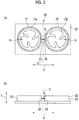
- the bellmouth 20 is provided with a base portion 23, a first mouth 21, and a second mouth 22, as shown in Figs. 2(a) and 2(b) .
- first mouth 21 and the second mouth 22 are referred to simply as mouths 21 and 22.
- the base portion 23 has a rectangular shape and is fixed to the housing 10 by fixing members.
- the first mouth 21 and the second mouth 22 are formed so as to stand from the base portion 23 ( Fig. 2(b) ) and are arranged side by side with a gap G therebetween in a width direction X ( Fig. 2(a) ).
- the first mouth 21 has a tubular shape and is provided so as to surround the first fan 17a.
- the first mouth 21 is provided with a clearance H provided between itself and the first fan 17a.
- a flat portion (a first flat portion) 24 is formed at a portion of a side wall of the first mouth 21.
- the flat portion 24 has a rectangular cross section and a flat surface is formed therein in a vertical direction Y.
- the cross section of the first mouth 21 has an arc shape with the exception of the flat portion 24.
- the second mouth 22 has a shape axisymmetric to the first mouth 21 with a reference line C as the axis of symmetry and is provided so as to surround the second fan 17b.
- the second mouth 22 has a flat portion (a second flat portion) 26 formed at a site facing the flat portion 24 of the first mouth 21. Further, the second mouth 22 is provided with a clearance H provided between itself and the second fan 17b.
- the gap G is set such that the flat portion 24 and the flat portion 26 come into contact with each other when the first mouth 21 and the second mouth 22 are displaced by being subjected to an external force. For this reason, when the maximum displacement amounts in a direction in which the first mouth 21 and the second mouth 22 approach each other when being subjected to an external force are respectively set to be L1 and L2, the gap G necessarily satisfies the relationship of G ⁇ L1+L2.
- the mouths 21 and 22 are formed of the same resin, and therefore, the gap G satisfies the relationship of G ⁇ 2 ⁇ L1 or G ⁇ 2xL2.
- the flat portion 24 is displaced in a direction coming close to the second mouth 22.
- the flat portion 26 is displaced in a direction coming close to the first mouth 21.
- the flat portion 24 comes into contact with the flat portion 26 at a predetermined position, as shown in Figs. 3 (a) and 3(b) . If the flat portions 24 and 26 come into contact with each other, the flat portion 24 receives a force in the opposite direction to the force when the flat portion 24 itself attempts to be displaced, from the flat portion 26. On the other hand, the flat portion 26 receives a force in the opposite direction to the force when the flat portion 26 itself attempts to be displaced, from the flat portion 24.
- the clearance H between the first fan 17a and the first mouth 21 and the clearance H between the second fan 17b and the second mouth 22 are substantially maintained. If the clearances H are maintained, a decrease in the performance of the blower 16, or breakage of the bellmouth 20 and/or the fans 17a and 17b due to contact between the bellmouth 20 and the fans 17a and 17b can be prevented.
- a bellmouth made of resin is mainly used in a blower having a one-fan specification in which a fan is one, because there is a concern that the bellmouth made of resin may be displaced if it is subjected to an external force.
- the bellmouth 20 made of resin according to this embodiment can be used in a blower having a two-fan specification in which two fans are provided, because even if the two mouths 21 and 22 are provided therein, displacement of them due to an external force can be suppressed.
- the bellmouth 20 of this embodiment is made of a resin material, and therefore, the bellmouth 20 can be formed by injection molding. For this reason, compared to a bellmouth made of metal, it is possible to freely change the heights of the mouths 21 and 22. By increasing the heights of the mouths 21 and 22, it is possible to improve the effect of blowing air which is discharged.
- the bellmouth 20 in which the mouths 21 and 22 are provided with the gap G provided therebetween has been described.
- a bellmouth 50 in which a first mouth 51 and a second mouth 52 are integrally formed is described.
- the same portions as those in the first embodiment are denoted by the same reference numerals and description thereof is omitted.
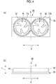
- the first mouth 51 and the second mouth 52 are integrally formed so as to stand from the base portion 23 and are arranged side by side in the width direction X, as shown in Figs. 4(a) and 4(b) .
- the first mouth 51 has a tubular shape and is provided so as to surround the first fan 17a.
- the first mouth 51 is provided with the clearance H provided between itself and the first fan 17a.
- the second mouth 52 has a shape axisymmetric to the first mouth 51 with the reference line C as the axis of symmetry and is provided so as to surround the second fan 17b.
- the second mouth 52 is provided with the clearance H provided between itself and the second fan 17b.
- connection portion a site at which the first mouth 51 and the second mouth 52 are integrated is, for convenience, referred to as a connection portion.
- the first mouth 51 and the second mouth 52 according to this embodiment are formed in an integrated fashion.
- a force (F1) is applied from the first mouth 51 side to the connection portion.
- a force (F2) is applied from the second mouth 52 side to the connection portion.
- the force F1 and the force F2 are in the opposite directions, and therefore, the forces which are applied to the connection portion cancel each other out. For this reason, the displacement of the mouths 51 and 52 is suppressed.
- the set clearances H can be maintained. For this reason, a decrease in the performance of the blower 16, or breakage of the bellmouth 50 and/or the fans 17a and 17b due to contact between the mouths 51 and 52 and the fans 17a and 17b can be prevented.
- the bellmouth 50 according to this embodiment can also be applied to the blower 16 having a two-fan specification, similar to the first embodiment. Further, the bellmouth 50 is formed by injection molding, whereby it is possible to adjust the heights of the mouths 51 and 52, and therefore, it is possible to improve the effect of blowing air which is discharged.
- the bellmouth 20 (50) in which the displacement of the mouths 21 and 22 (51 and 52) can be suppressed have been described.
- means for further suppressing the displacement of the mouths will be hereinafter described by taking the bellmouth 50 described in the second embodiment as an example.
- ribs 31 and 32 are respectively provided in circumferential directions of the outer peripheral walls of the mouths 51 and 52.
- the ribs 31 and 32 are made of a resin materials and formed integrally with the mouths 51 and 52.
- the rigidity of the mouths 51 and 52 is increased by providing the ribs 31 and 32, and therefore, it becomes difficult for the entirety of the mouths 51 and 52 to be displaced with respect to an external force. Then, the entirety of the mouths 51 and 52 can maintain the original shape, and therefore, it is possible to maintain the blowing effect of the bellmouth 50.
- the rib is not limited to a case of being provided at both the mouths 51 and 52 and may be provided at either of them.
- the ribs can also be provided at the mouths 21 and 22 of the first embodiment and can exhibit the same effects as the above-described effects.
- the mouths 21 and 22 having the flat portions 24 and 26 have been described.
- the outer peripheral wall of the first mouth 21 and the outer peripheral wall of the second mouth 22 come into contact with each other, thereby suppressing displacement from each other, and therefore, a decrease in the performance of the blower 16 or breakage of the bellmouth and/or the fans can be prevented.
- the ribs 31 and 32 are provided at the outer peripheral walls of the mouths.
- the ribs 31 and 32 can also be provided at the inner peripheral walls. Even in a case where the ribs 31 and 32 are provided at the inner peripheral walls, it is possible to improve the rigidity of the mouths.
Landscapes
- Engineering & Computer Science (AREA)
- Mechanical Engineering (AREA)
- General Engineering & Computer Science (AREA)
- Structures Of Non-Positive Displacement Pumps (AREA)
Abstract
Description
- The present invention relates to a blower and particularly, to a blower which is provided with a bellmouth made of resin.
- An air conditioner has an indoor unit which performs heat exchange with indoor air, and an outdoor unit which dissipates heat to the outside air or absorbs heat from the outside air and is provided with a blower. The blower is provided with a fan, and a bellmouth for surrounding the fan and blowing air. The bellmouth is installed with a constant clearance provided between itself and the fan. The smaller the clearance, the higher the blowing effect of the bellmouth becomes, and therefore, in general, the clearance is set to be small.
- A projection opening (hereinafter referred to as a mouth) configuring the bellmouth is provided to correspond to the number of fans. For example, in an outdoor unit of
PTL 1, two mouths are provided with a distance provided therebetween with respect to two fans arranged side by side in a vertical direction. - In a blower, a bellmouth made of metal or a bellmouth made of resin is used.
- A bellmouth made of metal has high rigidity, and therefore, a concern that the bellmouth may be deformed by an external force such as a snow load or a wind load is low. However, there is a restriction in processing, and therefore, the degree of freedom of a shape is low.
- On the other hand, a bellmouth made of resin can be formed by, for example, injection molding, and therefore, the degree of freedom of a shape becomes higher. However, rigidity is low, compared to a bellmouth made of metal, and therefore, there is a concern that the bellmouth may be bent and deformed by an external force.
- [PTL 1] Japanese Unexamined Patent Application Publication No.
2011-231985 - A bellmouth made of resin, in which two mouths are arranged side by side and integrally formed, is fixed by fixing members at both right and left ends. If an external force is applied to the bellmouth, in a central portion, there is no support for an external force, and therefore, there is a concern that the central portion of the bellmouth may be bent and dented. If the central portion of the bellmouth is dented, the mouths are displaced toward the center side, and therefore, a clearance (a first clearance) in an array direction of the mouths becomes greater and a clearance (a second clearance) in a direction perpendicular to the array direction becomes smaller. If the first clearance becomes greater, the blowing performance of the bellmouth is lowered, and thus the performance of an outdoor unit is lowered. On the other hand, if the second clearance becomes smaller, the fans and the bellmouth may interfere with each other, and thus there is a concern that breakage of the fans and/or the bellmouth may occur.
- The present invention has been made based on such a problem and has an object to provide a blower in which when a bellmouth made of resin, in which two mouths are arranged side by side, is subjected to an external force, the displacement of the mouths is suppressed.
- Under such an object, according to an aspect of the present invention, there is provided a blower including: a first fan; a second fan which is provided in parallel to the first fan; and a bellmouth which has a first mouth surrounding the first fan, and a second mouth surrounding the second fan, and is made of a resin material, wherein if the bellmouth is displaced by being subjected to an external force, a portion of the first mouth and a portion of the second mouth come into contact with each other.
- A portion of the first mouth and a portion of the second mouth face each other, and when the bellmouth is displaced, these sites come into contact with each other, whereby forces which are applied to the sites can cancel each other out. In this way, it is possible to suppress the displacement of the first mouth and the second mouth. Then, the clearances (the first clearance and the second clearance described above) between the first fan and the first mouth and between the second fan and the second mouth can be maintained, and therefore, a decrease in the performance of the blower or breakage of the bellmouth and/or the fans can be prevented.
- In the blower according to the present invention, it is preferable that the first mouth has a first flat portion, and the second mouth has a second flat portion, and if the bellmouth is displaced by being subjected to an external force, the first flat portion and the second flat portion come into contact with each other.
- In this way, forces which are applied to the sites (the first flat portion and the second flat portion) which are in contact with each other can cancel each other out without causing a local force.
- Further, according to another aspect of the present invention, there is provided a blower including: a first fan; a second fan which is provided in parallel to the first fan; and a bellmouth which has a first mouth surrounding the first fan, and a second mouth surrounding the second fan, and is made of a resin material, wherein the first mouth and the second mouth are integrally formed.
- The first mouth and the second mouth are integrally formed, whereby forces which are applied to an integrated site (a connection portion) can cancel each other out. For this reason, the clearances (the first clearance and the second clearance described above) between the first fan and the first mouth and between the second fan and the second mouth are maintained, and therefore, a decrease in the performance of the blower or breakage of the bellmouth and/or the fans can be prevented.
- In the blower according to the present invention, it is preferable that at least one of the first mouth and the second mouth has a rib formed therein in a circumferential direction.
- By forming the rib at the mouth, it is possible to improve the rigidity of the mouth, and therefore, the deformation of the entire mouth can be suppressed. Advantageous Effects of Invention
- According to the present invention, if the bellmouth made of resin is displaced by being subjected to an external force, a portion of the first mouth and a portion of the second mouth come into contact with each other, and therefore, it is possible to suppress the displacement of each mouth. Further, the first mouth and the second mouth are integrally formed, whereby the displacement of each mouth can be suppressed.
- For this reason, the initial clearance between the bellmouth and the fan can be maintained, and thus a decrease in the performance of the blower, or breakage of the bellmouth and/or fans which can be caused by contact between the bellmouth and the fans can be avoided.
-
-
Fig. 1 is a schematic front view showing an outdoor unit of an air conditioner according to this embodiment. -
Fig. 2(a) is a plan view showing a bellmouth according to a first embodiment, andFig. 2(b) is a front view of the bellmouth shown inFig. 2(a) . -
Fig. 3(a) is a plan view showing the bellmouth when it has been subjected to an external force, andFig. 3(b) is a front view of the bellmouth shown inFig. 3(a) . -
Fig. 4(a) is a plan view showing a bellmouth according to a second embodiment, andFig. 4(b) is a front view of the bellmouth shown inFig. 4(a) . -
Fig. 5(a) is a plan view showing a bellmouth according to a modification example, andFig. 5(b) is a front view of the bellmouth shown inFig. 5(a) . - Hereinafter, embodiments of the present invention will be described with reference to the accompanying drawings.
- As shown in
Fig. 1 , anoutdoor unit 1 of an air conditioner according to an embodiment of the present invention is provided with ahousing 10 having anintake port 12 formed in afront face 10a, aheat exchanger 15 which is provided in the interior of thehousing 10, and ablower 16 which discharges air which has passed through theheat exchanger 15. - The
blower 16 is provided with afan part 17 and abellmouth 20. Thefan part 17 has afirst fan 17a, and asecond fan 17b which is provided in parallel to thefirst fan 17a. - The present invention has features in the structure of the
bellmouth 20. - The
bellmouth 20 is provided so as to cover atop face 10b of thehousing 10 of theoutdoor unit 1. Thebellmouth 20 is made of a resin material and formed by, for example, injection molding. - The
bellmouth 20 is provided with abase portion 23, afirst mouth 21, and asecond mouth 22, as shown inFigs. 2(a) and 2(b) . Hereinafter, there are cases where thefirst mouth 21 and thesecond mouth 22 are referred to simply asmouths - The
base portion 23 has a rectangular shape and is fixed to thehousing 10 by fixing members. - The
first mouth 21 and thesecond mouth 22 are formed so as to stand from the base portion 23 (Fig. 2(b) ) and are arranged side by side with a gap G therebetween in a width direction X (Fig. 2(a) ). - The
first mouth 21 has a tubular shape and is provided so as to surround thefirst fan 17a. Thefirst mouth 21 is provided with a clearance H provided between itself and thefirst fan 17a. - A flat portion (a first flat portion) 24 is formed at a portion of a side wall of the
first mouth 21. Theflat portion 24 has a rectangular cross section and a flat surface is formed therein in a vertical direction Y. The cross section of thefirst mouth 21 has an arc shape with the exception of theflat portion 24. - The
second mouth 22 has a shape axisymmetric to thefirst mouth 21 with a reference line C as the axis of symmetry and is provided so as to surround thesecond fan 17b. - Further, the
second mouth 22 has a flat portion (a second flat portion) 26 formed at a site facing theflat portion 24 of thefirst mouth 21. Further, thesecond mouth 22 is provided with a clearance H provided between itself and thesecond fan 17b. - The gap G is set such that the
flat portion 24 and theflat portion 26 come into contact with each other when thefirst mouth 21 and thesecond mouth 22 are displaced by being subjected to an external force. For this reason, when the maximum displacement amounts in a direction in which thefirst mouth 21 and thesecond mouth 22 approach each other when being subjected to an external force are respectively set to be L1 and L2, the gap G necessarily satisfies the relationship of G<L1+L2. - Further, in this embodiment, the
mouths - Hereinafter, the operation and effects of the
bellmouth 20 according to this embodiment will be described. - If the
first mouth 21 is subjected to an external force, theflat portion 24 is displaced in a direction coming close to thesecond mouth 22. On the other hand, if thesecond mouth 22 is subjected to an external force, theflat portion 26 is displaced in a direction coming close to thefirst mouth 21. - If the
flat portions flat portion 24 comes into contact with theflat portion 26 at a predetermined position, as shown inFigs. 3 (a) and 3(b) . If theflat portions flat portion 24 receives a force in the opposite direction to the force when theflat portion 24 itself attempts to be displaced, from theflat portion 26. On the other hand, theflat portion 26 receives a force in the opposite direction to the force when theflat portion 26 itself attempts to be displaced, from theflat portion 24. - Then, the forces which are applied to the
flat portions mouths flat portions - For this reason, the clearance H between the
first fan 17a and thefirst mouth 21 and the clearance H between thesecond fan 17b and thesecond mouth 22 are substantially maintained. If the clearances H are maintained, a decrease in the performance of theblower 16, or breakage of thebellmouth 20 and/or thefans fans - Further, in the related art, a bellmouth made of resin is mainly used in a blower having a one-fan specification in which a fan is one, because there is a concern that the bellmouth made of resin may be displaced if it is subjected to an external force. However, the
bellmouth 20 made of resin according to this embodiment can be used in a blower having a two-fan specification in which two fans are provided, because even if the twomouths - Further, the
bellmouth 20 of this embodiment is made of a resin material, and therefore, thebellmouth 20 can be formed by injection molding. For this reason, compared to a bellmouth made of metal, it is possible to freely change the heights of themouths mouths - In the first embodiment, the
bellmouth 20 in which themouths bellmouth 50 in which afirst mouth 51 and asecond mouth 52 are integrally formed is described. In addition, the same portions as those in the first embodiment are denoted by the same reference numerals and description thereof is omitted. - The
first mouth 51 and thesecond mouth 52 are integrally formed so as to stand from thebase portion 23 and are arranged side by side in the width direction X, as shown inFigs. 4(a) and 4(b) . - The
first mouth 51 has a tubular shape and is provided so as to surround thefirst fan 17a. - The
first mouth 51 is provided with the clearance H provided between itself and thefirst fan 17a. - The
second mouth 52 has a shape axisymmetric to thefirst mouth 51 with the reference line C as the axis of symmetry and is provided so as to surround thesecond fan 17b. Thesecond mouth 52 is provided with the clearance H provided between itself and thesecond fan 17b. - In addition, a site at which the
first mouth 51 and thesecond mouth 52 are integrated is, for convenience, referred to as a connection portion. - The
first mouth 51 and thesecond mouth 52 according to this embodiment are formed in an integrated fashion. - If the
first mouth 51 is subjected to an external force, a force (F1) is applied from thefirst mouth 51 side to the connection portion. Similarly, if thesecond mouth 52 is subjected to an external force, a force (F2) is applied from thesecond mouth 52 side to the connection portion. - The force F1 and the force F2 are in the opposite directions, and therefore, the forces which are applied to the connection portion cancel each other out. For this reason, the displacement of the
mouths - If the displacement of the
mouths blower 16, or breakage of thebellmouth 50 and/or thefans mouths fans - Further, the
bellmouth 50 according to this embodiment can also be applied to theblower 16 having a two-fan specification, similar to the first embodiment. Further, thebellmouth 50 is formed by injection molding, whereby it is possible to adjust the heights of themouths - In the above embodiments, the bellmouth 20 (50) in which the displacement of the
mouths 21 and 22 (51 and 52) can be suppressed have been described. In a modification example, means for further suppressing the displacement of the mouths will be hereinafter described by taking thebellmouth 50 described in the second embodiment as an example. - As shown in
Figs. 5(a) and 5(b) ,ribs mouths ribs mouths - The rigidity of the
mouths ribs mouths mouths bellmouth 50. - In addition, the rib is not limited to a case of being provided at both the
mouths - Further, the ribs can also be provided at the
mouths - The embodiments have been described above. However, in addition to these, as long as it does not depart from the gist of the present invention, it is possible to select the configurations mentioned in the above embodiments or appropriately change them to other configurations.
- For example, in the first embodiment, the
mouths flat portions flat portions first mouth 21 and the outer peripheral wall of thesecond mouth 22 come into contact with each other, thereby suppressing displacement from each other, and therefore, a decrease in the performance of theblower 16 or breakage of the bellmouth and/or the fans can be prevented. - Further, in the modification example, the
ribs ribs ribs -
- 1:
- outdoor unit
- 10:
- housing
- 10a:
- front face
- 10b:
- top face
- 12:
- intake port
- 15:
- heat exchanger
- 16:
- blower
- 17:
- fan part
- 17a:
- first fan
- 17b:
- second fan
- 20:
- bellmouth
- 21:
- first mouth
- 22:
- second mouth
- 23:
- base portion
- 24:
- flat portion (first flat portion)
- 26:
- flat portion (second flat portion)
- 31,
- 32: rib
- 50:
- bellmouth
- 51:
- first mouth
- 52:
- second mouth
- C:
- reference line
- G:
- gap
- H:
- clearance
- X:
- width direction
- Y:
- vertical direction
Claims (5)
- A blower comprising:a first fan;a second fan which is provided in parallel to the first fan; anda bellmouth which has a first mouth surrounding the first fan, and a second mouth surrounding the second fan, and is made of a resin material,wherein if the bellmouth is displaced by being subjected to an external force, a portion of the first mouth and a portion of the second mouth come into contact with each other.
- The blower according to Claim 1, wherein the first mouth has a first flat portion, and the second mouth has a second flat portion, and
if the bellmouth is displaced by being subjected to an external force, the first flat portion and the second flat portion come into contact with each other. - A blower comprising:a first fan;a second fan which is provided in parallel to the first fan; anda bellmouth which has a first mouth surrounding the first fan, and a second mouth surrounding the second fan, and is made of a resin material,wherein the first mouth and the second mouth are integrally formed.
- The blower according to any one of Claims 1 to 3, wherein at least one of the first mouth and the second mouth has a rib formed therein in a circumferential direction.
- An outdoor unit of an air conditioner comprising: the blower according to any one of Claims 1 to 4.
Applications Claiming Priority (2)
| Application Number | Priority Date | Filing Date | Title |
|---|---|---|---|
| JP2013258800A JP6203623B2 (en) | 2013-12-16 | 2013-12-16 | Blower |
| PCT/JP2014/003196 WO2015092947A1 (en) | 2013-12-16 | 2014-06-16 | Blower |
Publications (2)
| Publication Number | Publication Date |
|---|---|
| EP3034888A1 true EP3034888A1 (en) | 2016-06-22 |
| EP3034888A4 EP3034888A4 (en) | 2016-08-17 |
Family
ID=53402338
Family Applications (1)
| Application Number | Title | Priority Date | Filing Date |
|---|---|---|---|
| EP14871395.1A Withdrawn EP3034888A4 (en) | 2013-12-16 | 2014-06-16 | BLOWER |
Country Status (3)
| Country | Link |
|---|---|
| EP (1) | EP3034888A4 (en) |
| JP (1) | JP6203623B2 (en) |
| WO (1) | WO2015092947A1 (en) |
Cited By (1)
| Publication number | Priority date | Publication date | Assignee | Title |
|---|---|---|---|---|
| CN107850089A (en) * | 2015-09-16 | 2018-03-27 | 三菱重工制冷空调系统株式会社 | Pressure fan |
Family Cites Families (11)
| Publication number | Priority date | Publication date | Assignee | Title |
|---|---|---|---|---|
| JPS54128148A (en) * | 1978-03-28 | 1979-10-04 | Toshiba Corp | Air conditioner |
| JPS633440Y2 (en) * | 1980-04-04 | 1988-01-27 | ||
| JPH07305868A (en) * | 1994-05-13 | 1995-11-21 | Mitsubishi Heavy Ind Ltd | Air-supply device and outdoor unit for air-conditioning machine equipped therewith |
| JP2001153400A (en) * | 1999-11-26 | 2001-06-08 | Hitachi Ltd | Outdoor unit of air conditioner |
| JP4744256B2 (en) * | 2005-09-30 | 2011-08-10 | 三洋電機株式会社 | Outdoor unit |
| US7907403B2 (en) * | 2005-10-25 | 2011-03-15 | Hewlett-Packard Development Company, L.P. | Active heat sink with multiple fans |
| GB2442979B (en) * | 2006-10-17 | 2011-10-05 | Farmer Controls Plc | Extraction unit |
| JP2008202890A (en) * | 2007-02-21 | 2008-09-04 | Yanmar Co Ltd | Air conditioning device |
| US7640897B2 (en) * | 2007-08-08 | 2010-01-05 | Sauer-Danfoss, Inc. | Fan design and method of operating |
| JP2009195045A (en) * | 2008-02-15 | 2009-08-27 | Denso Corp | Blower for vehicle |
| JP5569127B2 (en) | 2010-04-28 | 2014-08-13 | ダイキン工業株式会社 | Air conditioner outdoor unit |
-
2013
- 2013-12-16 JP JP2013258800A patent/JP6203623B2/en active Active
-
2014
- 2014-06-16 EP EP14871395.1A patent/EP3034888A4/en not_active Withdrawn
- 2014-06-16 WO PCT/JP2014/003196 patent/WO2015092947A1/en not_active Ceased
Cited By (1)
| Publication number | Priority date | Publication date | Assignee | Title |
|---|---|---|---|---|
| CN107850089A (en) * | 2015-09-16 | 2018-03-27 | 三菱重工制冷空调系统株式会社 | Pressure fan |
Also Published As
| Publication number | Publication date |
|---|---|
| JP2015113818A (en) | 2015-06-22 |
| EP3034888A4 (en) | 2016-08-17 |
| WO2015092947A1 (en) | 2015-06-25 |
| JP6203623B2 (en) | 2017-09-27 |
Similar Documents
| Publication | Publication Date | Title |
|---|---|---|
| JP6082520B2 (en) | Impeller used for axial flow fan and axial flow fan using the same | |
| US11162693B2 (en) | Fan unit, and outdoor unit of air conditioner comprising fan unit | |
| US9541297B2 (en) | Heating ventilator for bathroom | |
| EP3171492B1 (en) | Rotating electric machine | |
| US10113755B2 (en) | Outdoor unit of air conditioner | |
| US20130309064A1 (en) | Fan with integrated vibration absorbing structure | |
| US11085654B2 (en) | Outdoor unit for air conditioner | |
| US10240805B2 (en) | Indoor unit for air conditioner | |
| US9175899B2 (en) | Air conditioner | |
| EP2930441A1 (en) | Outdoor machine for air-conditioner | |
| US20100225184A1 (en) | Servo motor with improved heat dissipation efficiency | |
| CN106016544B (en) | Support protection part and air conditioner all-in-one machine | |
| JP6238855B2 (en) | Electronics | |
| JP6203623B2 (en) | Blower | |
| US20240155812A1 (en) | Cooling device for electronic equipment | |
| US10828967B2 (en) | Air conditioning device for vehicle | |
| JP2012042141A (en) | Outdoor unit of air conditioner | |
| JP6056832B2 (en) | Fan motor stand | |
| JP2014015863A (en) | Cooling fan device | |
| JP6769258B2 (en) | Electrical equipment | |
| CN205825300U (en) | Support protector and air conditioner integrated machine | |
| EP3299636A1 (en) | Blower | |
| CN210241930U (en) | Air duct for cooling device and cooling device | |
| KR20160090249A (en) | Fan Shroud for Motor Vehicle | |
| CN101198794A (en) | Air blower and outdoor unit for air conditioner having same |
Legal Events
| Date | Code | Title | Description |
|---|---|---|---|
| PUAI | Public reference made under article 153(3) epc to a published international application that has entered the european phase |
Free format text: ORIGINAL CODE: 0009012 |
|
| 17P | Request for examination filed |
Effective date: 20160316 |
|
| AK | Designated contracting states |
Kind code of ref document: A1 Designated state(s): AL AT BE BG CH CY CZ DE DK EE ES FI FR GB GR HR HU IE IS IT LI LT LU LV MC MK MT NL NO PL PT RO RS SE SI SK SM TR |
|
| AX | Request for extension of the european patent |
Extension state: BA ME |
|
| A4 | Supplementary search report drawn up and despatched |
Effective date: 20160719 |
|
| RIC1 | Information provided on ipc code assigned before grant |
Ipc: F04D 25/16 20060101ALI20160713BHEP Ipc: F04D 29/54 20060101AFI20160713BHEP Ipc: F04D 25/08 20060101ALI20160713BHEP |
|
| DAX | Request for extension of the european patent (deleted) | ||
| RAP1 | Party data changed (applicant data changed or rights of an application transferred) |
Owner name: MITSUBISHI HEAVY INDUSTRIES THERMAL SYSTEMS, LTD. |
|
| GRAP | Despatch of communication of intention to grant a patent |
Free format text: ORIGINAL CODE: EPIDOSNIGR1 |
|
| STAA | Information on the status of an ep patent application or granted ep patent |
Free format text: STATUS: GRANT OF PATENT IS INTENDED |
|
| INTG | Intention to grant announced |
Effective date: 20190321 |
|
| STAA | Information on the status of an ep patent application or granted ep patent |
Free format text: STATUS: THE APPLICATION IS DEEMED TO BE WITHDRAWN |
|
| 18D | Application deemed to be withdrawn |
Effective date: 20190801 |