EP3034876A1 - Pressure-setting regulator - Google Patents
Pressure-setting regulator Download PDFInfo
- Publication number
- EP3034876A1 EP3034876A1 EP15201260.5A EP15201260A EP3034876A1 EP 3034876 A1 EP3034876 A1 EP 3034876A1 EP 15201260 A EP15201260 A EP 15201260A EP 3034876 A1 EP3034876 A1 EP 3034876A1
- Authority
- EP
- European Patent Office
- Prior art keywords
- pressure
- regulator
- outlet
- knob
- outlet pressure
- Prior art date
- Legal status (The legal status is an assumption and is not a legal conclusion. Google has not performed a legal analysis and makes no representation as to the accuracy of the status listed.)
- Withdrawn
Links
Images


Classifications
-
- F—MECHANICAL ENGINEERING; LIGHTING; HEATING; WEAPONS; BLASTING
- F16—ENGINEERING ELEMENTS AND UNITS; GENERAL MEASURES FOR PRODUCING AND MAINTAINING EFFECTIVE FUNCTIONING OF MACHINES OR INSTALLATIONS; THERMAL INSULATION IN GENERAL
- F16K—VALVES; TAPS; COCKS; ACTUATING-FLOATS; DEVICES FOR VENTING OR AERATING
- F16K31/00—Actuating devices; Operating means; Releasing devices
- F16K31/44—Mechanical actuating means
- F16K31/50—Mechanical actuating means with screw-spindle or internally threaded actuating means
-
- F—MECHANICAL ENGINEERING; LIGHTING; HEATING; WEAPONS; BLASTING
- F04—POSITIVE - DISPLACEMENT MACHINES FOR LIQUIDS; PUMPS FOR LIQUIDS OR ELASTIC FLUIDS
- F04B—POSITIVE-DISPLACEMENT MACHINES FOR LIQUIDS; PUMPS
- F04B35/00—Piston pumps specially adapted for elastic fluids and characterised by the driving means to their working members, or by combination with, or adaptation to, specific driving engines or motors, not otherwise provided for
- F04B35/04—Piston pumps specially adapted for elastic fluids and characterised by the driving means to their working members, or by combination with, or adaptation to, specific driving engines or motors, not otherwise provided for the means being electric
-
- F—MECHANICAL ENGINEERING; LIGHTING; HEATING; WEAPONS; BLASTING
- F04—POSITIVE - DISPLACEMENT MACHINES FOR LIQUIDS; PUMPS FOR LIQUIDS OR ELASTIC FLUIDS
- F04B—POSITIVE-DISPLACEMENT MACHINES FOR LIQUIDS; PUMPS
- F04B35/00—Piston pumps specially adapted for elastic fluids and characterised by the driving means to their working members, or by combination with, or adaptation to, specific driving engines or motors, not otherwise provided for
- F04B35/01—Piston pumps specially adapted for elastic fluids and characterised by the driving means to their working members, or by combination with, or adaptation to, specific driving engines or motors, not otherwise provided for the means being mechanical
-
- F—MECHANICAL ENGINEERING; LIGHTING; HEATING; WEAPONS; BLASTING
- F04—POSITIVE - DISPLACEMENT MACHINES FOR LIQUIDS; PUMPS FOR LIQUIDS OR ELASTIC FLUIDS
- F04B—POSITIVE-DISPLACEMENT MACHINES FOR LIQUIDS; PUMPS
- F04B35/00—Piston pumps specially adapted for elastic fluids and characterised by the driving means to their working members, or by combination with, or adaptation to, specific driving engines or motors, not otherwise provided for
- F04B35/06—Mobile combinations
-
- F—MECHANICAL ENGINEERING; LIGHTING; HEATING; WEAPONS; BLASTING
- F04—POSITIVE - DISPLACEMENT MACHINES FOR LIQUIDS; PUMPS FOR LIQUIDS OR ELASTIC FLUIDS
- F04B—POSITIVE-DISPLACEMENT MACHINES FOR LIQUIDS; PUMPS
- F04B39/00—Component parts, details, or accessories, of pumps or pumping systems specially adapted for elastic fluids, not otherwise provided for in, or of interest apart from, groups F04B25/00 - F04B37/00
- F04B39/10—Adaptations or arrangements of distribution members
- F04B39/1066—Valve plates
-
- F—MECHANICAL ENGINEERING; LIGHTING; HEATING; WEAPONS; BLASTING
- F04—POSITIVE - DISPLACEMENT MACHINES FOR LIQUIDS; PUMPS FOR LIQUIDS OR ELASTIC FLUIDS
- F04B—POSITIVE-DISPLACEMENT MACHINES FOR LIQUIDS; PUMPS
- F04B39/00—Component parts, details, or accessories, of pumps or pumping systems specially adapted for elastic fluids, not otherwise provided for in, or of interest apart from, groups F04B25/00 - F04B37/00
- F04B39/12—Casings; Cylinders; Cylinder heads; Fluid connections
- F04B39/121—Casings
-
- F—MECHANICAL ENGINEERING; LIGHTING; HEATING; WEAPONS; BLASTING
- F04—POSITIVE - DISPLACEMENT MACHINES FOR LIQUIDS; PUMPS FOR LIQUIDS OR ELASTIC FLUIDS
- F04B—POSITIVE-DISPLACEMENT MACHINES FOR LIQUIDS; PUMPS
- F04B39/00—Component parts, details, or accessories, of pumps or pumping systems specially adapted for elastic fluids, not otherwise provided for in, or of interest apart from, groups F04B25/00 - F04B37/00
- F04B39/12—Casings; Cylinders; Cylinder heads; Fluid connections
- F04B39/123—Fluid connections
-
- F—MECHANICAL ENGINEERING; LIGHTING; HEATING; WEAPONS; BLASTING
- F04—POSITIVE - DISPLACEMENT MACHINES FOR LIQUIDS; PUMPS FOR LIQUIDS OR ELASTIC FLUIDS
- F04B—POSITIVE-DISPLACEMENT MACHINES FOR LIQUIDS; PUMPS
- F04B41/00—Pumping installations or systems specially adapted for elastic fluids
- F04B41/02—Pumping installations or systems specially adapted for elastic fluids having reservoirs
-
- F—MECHANICAL ENGINEERING; LIGHTING; HEATING; WEAPONS; BLASTING
- F04—POSITIVE - DISPLACEMENT MACHINES FOR LIQUIDS; PUMPS FOR LIQUIDS OR ELASTIC FLUIDS
- F04B—POSITIVE-DISPLACEMENT MACHINES FOR LIQUIDS; PUMPS
- F04B49/00—Control, e.g. of pump delivery, or pump pressure of, or safety measures for, machines, pumps, or pumping installations, not otherwise provided for, or of interest apart from, groups F04B1/00 - F04B47/00
- F04B49/08—Regulating by delivery pressure
-
- F—MECHANICAL ENGINEERING; LIGHTING; HEATING; WEAPONS; BLASTING
- F04—POSITIVE - DISPLACEMENT MACHINES FOR LIQUIDS; PUMPS FOR LIQUIDS OR ELASTIC FLUIDS
- F04B—POSITIVE-DISPLACEMENT MACHINES FOR LIQUIDS; PUMPS
- F04B49/00—Control, e.g. of pump delivery, or pump pressure of, or safety measures for, machines, pumps, or pumping installations, not otherwise provided for, or of interest apart from, groups F04B1/00 - F04B47/00
- F04B49/22—Control, e.g. of pump delivery, or pump pressure of, or safety measures for, machines, pumps, or pumping installations, not otherwise provided for, or of interest apart from, groups F04B1/00 - F04B47/00 by means of valves
-
- F—MECHANICAL ENGINEERING; LIGHTING; HEATING; WEAPONS; BLASTING
- F04—POSITIVE - DISPLACEMENT MACHINES FOR LIQUIDS; PUMPS FOR LIQUIDS OR ELASTIC FLUIDS
- F04B—POSITIVE-DISPLACEMENT MACHINES FOR LIQUIDS; PUMPS
- F04B53/00—Component parts, details or accessories not provided for in, or of interest apart from, groups F04B1/00 - F04B23/00 or F04B39/00 - F04B47/00
- F04B53/14—Pistons, piston-rods or piston-rod connections
-
- F—MECHANICAL ENGINEERING; LIGHTING; HEATING; WEAPONS; BLASTING
- F16—ENGINEERING ELEMENTS AND UNITS; GENERAL MEASURES FOR PRODUCING AND MAINTAINING EFFECTIVE FUNCTIONING OF MACHINES OR INSTALLATIONS; THERMAL INSULATION IN GENERAL
- F16K—VALVES; TAPS; COCKS; ACTUATING-FLOATS; DEVICES FOR VENTING OR AERATING
- F16K37/00—Special means in or on valves or other cut-off apparatus for indicating or recording operation thereof, or for enabling an alarm to be given
- F16K37/0008—Mechanical means
- F16K37/0016—Mechanical means having a graduated scale
Definitions
- the invention relates to a pressure regulator.
- An embodiment of the present invention is directed to an air compressor that eliminates the regulator pressure gauge and allows the regulator to manually be set to a predetermined pressure.
- a pressure regulator can have a scale indicating a number of outlet pressures which can be set as a selected outlet pressure of a gas exiting the pressure regulator.
- a regulator knob can be adapted to be rotated manually to a selected outlet pressure chosen from the number of outlet pressures.
- a regulator spring can be used that at least in part controls a valve that regulates a flow of the gas. The regulator knob can be adapted to change a spring compression of the regulator spring when the regulator knob is manually rotated to set the selected outlet pressure of the gas.
- rotation of the regulator knob to the selected outlet pressure, as well as setting a selected outlet pressure can be free of a feedback control mechanism.
- the selected outlet pressure can be set by the regulator knob to a value selected on the scale and the pressure regulator can be configured to produce an outlet pressure free of reference to an outlet pressure gauge.
- the scale can be of a variety of configurations.
- the scale can be configured to be generally coaxial with the circumference of the regulator knob.
- the scale can be configured to be generally coaxial with the circumference of the regulator knob and can indicate a plurality of outlet pressures which can be selected and which have one or more of the plurality of outlet pressures in a range of from 25 psig to 250 psig, or higher.
- the regulator knob can also have of a variety of designs.
- the regulator knob can have single-turn coarse grooves which slideably engage single-turn coarse threads which project from a portion of a regulator body, such as a control cylinder.
- the regulator knob can have an indicium which can be aligned with a portion of the scale to set the selected outlet pressure.
- the indicium can be an arrow, such as a set point arrow, which can be pointed to a pressure indicated by the scale to set a selected outlet pressure.
- the rotation of the regulator knob and the indication of its position can have a variety of mechanisms, in an embodiment the regulator knob can be ratcheted when rotated to cause an alignment of a portion of the regulator knob to a portion of the scale to set the selected outlet pressure.
- a pressure control system can have the pressure regulator which can have a regulator knob which can be rotated to control an outlet pressure of a gas exiting the pressure regulator.
- the pressure control system can also have the scale configured proximate to the regulator knob and indicating a plurality of outlet pressure values one of which can be selected as an outlet set pressure; an indicium mounted on and moved by the regulator knob, the indicium proximate to an outlet pressure value that is selected as an outlet set pressure.
- the outlet set pressure can be selected by rotating the regulator knob to control the outlet pressure of the gas exiting the regulator at a desired outlet set pressure.
- the pressure control system can have a control cylinder can have a single-turn course thread projecting from a portion of a regulator body.
- the single-turn course thread can be configured to slideably engage the regulator knob.
- the pressure control system can use a regulator knob which is a single-turn regulator knob.
- the pressure control system can control the outlet pressure to within 15 percent, or 10 percent, or closer, of an outlet set pressure when the regulator knob remains in a fixed position corresponding to a selected outlet pressure.
- the pressure control system can be configured to indicate an outlet pressure midpoint when the regulator knob is rotated to a point that is located at about one-half of its rotational range.
- a compressor can have the pressure-setting regulator and/or the pressure control system which uses the pressure-setting regulator.
- a compressor for producing a compressed gas can have the pressure regulator, a scale indicating a plurality of outlet pressures which can be set as a selected outlet pressure of a gas exiting the regulator and a regulator knob adapted to be manually rotated to set the selected outlet pressure from the plurality of outlet pressures of the scale.
- a regulator spring can at least in part control a valve that regulates a flow of the gas of the pressure-setting regulator.
- the regulator knob can be adapted to change a spring compression of the regulator spring when the regulator knob is manually rotated to set the selected outlet pressure of the gas.
- the scale can be configured proximate to the regulator knob.
- a positive control method of pressure regulation can use the pressure-setting regulator.
- a method of controlling the regulator outlet pressure can have the steps of: providing a regulator having a single-turn regulator knob which has an indicium adapted to indicated a portion of the scale; providing the scale configured proximate to the single-turn regulator knob and having a plurality of outlet pressures; rotating the single-turn regulator knob such that the indicium indicates an outlet pressure which is an outlet pressure set point; and in which the rotating of the single-turn regulator knob changes the pressure exerted by a regulator spring which changes the differential pressure of the regulator to change the outlet pressure.
- the method of controlling regulator outlet pressure can control the controlling the outlet pressure within 20 percent of the outlet pressure set point.
- the pressure-setting regulator can be set to an outlet pressure by rotating the regulator knob such that the indicium, such as the set point arrow, is proximate to a selected outlet pressure.
- the regulator knob can be calibrated to position the indicium, such as an arrow or other mark, such that it is configured at the mid-range of the single-turn regulator knob rotational range.
- the pressure-setting regulator can be calibrated to achieve a minimum variance in the outlet pressure when the indicium is at a position within 45 degrees of the rotational mid-point of the regulator knob.
- the invention relates to the many and varied embodiments of a positive control regulator, pressure regulation system and to methods for regulating outlet gas pressure from a compressor.
- the pressure regulation system can be used with a compressor assembly which can compress air, or a gas, or gas mixtures.
- the compressor can compress one or more gases, inert gases, or mixed gas compositions.
- FIG. 1 shows an existing air compressor employing a feedback control system having a regulator and an outlet pressure gauge.
- existing air compressors have a manifold including a regulator for increasing or decreasing the pressure output to a connected power tool.
- the regulator can be in the form of an old-style regulator knob 121 that is connected to a pressure regulator valve that opens and closes to admit and obstruct, respectively, the flow of pressurized air into the power tool.
- the regulator is connected to a regulator outlet pressure gauge 122 that measures the regulator pressure and provides an indication of the measurement in a form such as a dial that can be read by the user.
- FIG. 2 shows a perspective view of a compressor assembly 20.
- the compressor assembly 20 can compress air, or can compress one or more gases, or gas mixtures.
- the compressor assembly 20 can be portable and can have a handle 29, which optionally can be a portion of compressor body 13.
- air herein is intended to be very broad.
- air includes breathable air, ambient air, treated air, conditioned air, clean room air, cooled air, heated air, non-flammable oxygen containing gas, filtered air, purified air, contaminated air, air with particulates solids or water, air from bone dry ( i.e. 0.00 humidity) air to air which is supersaturated with water, as well as any other type of air present in an environment in which a gas (e.g. air) compressor can be used. It is intended that cooling gases which are not air are encompassed by this disclosure.
- a cooling gas can be nitrogen, can comprise a gas mixture, can comprise nitrogen, can comprise oxygen (in a safe concentration), can comprise carbon dioxide, can comprise one inert gas or a plurality of inert gases, or comprise a mixture of gases.
- the compressor assembly 20 can have a pressure-setting regulator 400 configured at least in part within a housing 21.
- the compressor assembly includes a tank pressure gauge 325, a regulator knob 410 and a tool connect member 10 located on a face of the housing 21.
- An ON/OFF switch 11 can be located on a front portion of the housing 21.
- the regulator knob 410 is the control which controls the pressure-setting regulator 400 that is set within a desired air outlet pressure guide.
- the regulator knob 410 that is rotatable to a position that corresponds to the desired air output pressure to the tool.
- the desired air outlet pressure guide which can be a scale 500, is located on a dashboard 300 on the face of the housing 21 to be readable by an operator.
- the outlet pressure guide can optionally be in the form of a label.
- the outlet pressure guide can be integrally molded with the manifold, or etched thereon.
- the regulator outlet pressure gauge 122 of the prior art shown in FIG. 1 is no longer needed.
- users can rotate the regulator knob to set the desired outlet pressure, and not have to wait for a pressure gauge to catch up to the regulator set pressure and/or perform back and forth adjustments.
- the scale 500 can be configured to be generally coaxial with the circumference of the regulator knob 410.
- a generally coaxial configuration can allow an indicium of the regulator knob 410, such as set point arrow 420, to be aligned with, or positioned proximate to, a value of outlet pressure on the scale 500.
- the regulator knob 410 that has an indicium, such as set point arrow 420 can be turned to align with or point to a desired outlet pressure 550 which by such alignment positively sets that an outlet pressure 550 which is desired, and positively controls and maintains the desired outlet pressure.
- FIG. 2 illustrates an example embodiment of the air compressor in which the tool connect member 10 is located on the intake fan side 14 of the housing 21.
- the compressor assembly 20 can have a weight between 15 lbs and 100 lbs. In an embodiment, a portable embodiment of the compressor assembly 20 can have of weight between 10 lbs and 50 lbs, such as 10 lbs to 30 lbs, or 15 lbs to 40 lbs.
- the housing 21 can have a front housing 161 and a rear housing 170 and a plurality of intake ports 182.
- the compressor assembly can be cooled by air flow provided by a fan 200 the plurality of intake ports 182.
- Power can be supplied to a motor 33 of the compressor assembly through a power cord 5 extending through the housing 21.
- the compressor assembly 20 can comprise one or more of a cord holder member, such as a first cord wrap 6 and a second cord wrap 7.
- the power switch 11 can be used to change the operating state of the compressor assembly 20 at least from an "on” to an “off” state, and vice versa.
- the compressor In the “on” state, the compressor can be in a compressing state (also herein as a “pumping state”) in which it is compressing air, or a gas, or a plurality of gases, or a gas mixture.
- the dashboard 300 can provide an operator-accessible location for connections, gauges and valves which can be connected to a manifold 303 ( FIG. 3 ).
- the dashboard 300 can provide an operator access in a non-limiting example to the tool connect member 10, the pressure-setting regulator 400 and the tank pressure gauge 325.
- a compressed gas outlet line, hose or other device to receive compressed gas can be connected the tool connect member 10.
- a plurality of intake ports 182 can be formed in the housing 21 proximate to the fan 200 and a plurality of exhaust ports 31 (not shown) can be formed in the housing 21 proximate to the pump.
- the cooling gas employed to cool the compressor assembly 20 and its components can be air, which optionally can be taken in from the environment in which the compressor assembly 20 is placed.
- the cooling gas can be exhausted from the compressor assembly 20 through a plurality of exhaust ports (not shown).
- FIG. 3 illustrates the compressor assembly 20 with a portion of the housing 21 removed and showing the internal components of the compressor assembly.
- the pump assembly 25 compresses a gas, air or gas mixture.
- the pump assembly 25 can be powered by the motor 33 ( e.g. FIG. 3 ).
- the manifold 303 is shown having the pressure-setting regulator 400 and being free of an outlet pressure gauge.
- the compressed gas tank 150 can operate at a pressure in a range of at least from ambient pressure, e.g. 14.7 psig to 3000 psig ("psig" is the unit lbf/in ⁇ 2 gauge), or greater. In an embodiment, the compressed gas tank 150 can operate at 200 psig. In an embodiment, the compressed gas tank 150 can operate at 150 psig.
- the pressure-setting regulator 400 can use a pressure regulating valve.
- excess air pressure can be vented to atmosphere through a pressure relief valve 199, such as a spring loaded safety valve.
- the pump assembly 25 and the compressed gas tank 150 can be connected to a frame 111 ( FIG. 3 ).
- the compressor has a pressure regulated on/off switch which can stop the pump assembly 25 when a specified compressed gas tank pressure is obtained. Activation of the pump assembly 25 can occur at a pressure in a wide range of set operating pressure, e.g. 25 percent to 99.5 percent of specified compressed gas tank operating pressure.
- the specified compressed gas tank operating pressure can be in a range from 25 psig to 3000 psig.
- the specified compressed gas tank 150 pressure can be 50 psig, 75 psig, 100 psig, 150 psig, 200 psig, 250 psig, 300 psig, 500 psig, 1000 psig, 2000 psig, 3000 psig, or greater than or less than, or a value in between these example numbers.
- FIG. 4 shows a pump-side view of components of the pump assembly 25.
- FIG. 4 shows the mechanical design of the compressor assembly 20 having the pressure-setting regulator without the housing 21.
- a feed air for compression can be fed to the cylinder head 61 of the pump assembly 25.
- the feed air can be compressed in a pump cylinder 60 by a piston 63 to produce a compressed gas stream 510 ( FIG. 7 ) from the cylinder head 61 and can pass through a compressed gas outlet line 145 to enter the compressed gas tank 150.
- the motor 33 can operate at a motor speed between 1,000 rpm and 30,000 rpm. In an embodiment, the motor 33 can operate at a speed in a range of between 7,500 rpm and 12,000 rpm. In further embodiments, the motor 33 can operate at e.g. 11,252 rpm, or 11,000 rpm; or 10,000 rpm; or 9,000 rpm; or 7,500 rpm; or 6,000 rpm; or 5,000 rpm.
- the motor can be a non-synchronous universal motor rated, for example, at 1/2 horsepower, at 3/4 horsepower, at 1 horsepower, at 2 horsepower, at 5 horseposer or greater. In an embodiment, the motor can be a synchronous motor.
- the compressor assembly 20 can accommodate a variety of types of motor 33.
- the pressure-setting regulator 400 can be used in large-scale industrial equipment and compressors, as well as in portable equipment and compressors.
- the pump assembly 25 can have the components which are attached to the motor and/or which serve to compress a gas; which in a non-limiting example can comprise the fan 200, the motor 33, and a pump 59, with a pump arm 91.
- the pump assembly 25 can have the pump 59, such as a "gas pump” or an “air pump” that includes a piston 63, a pump cylinder 60, in which a piston 63 reciprocates and a connecting rod 69.
- the pump further includes a pulley 66, a drive belt 65 and driving mechanism driven by motor 33.
- the connecting rod 69 can connect to the piston 63 which can move inside of the pump cylinder 60.
- the motor can be a high speed universal motor, or other type of motor.
- the piston 63 can compress a gas in the pump cylinder 60 pumping the compressed gas through the valve plate assembly 62 into the cylinder head 61 and then out through a compressed gas outlet port 782 through an outlet line 145 and into the compressed gas tank 150.
- the pulley 66 and a sprocket 49 can in part drive the drive belt 65, and can be sized to achieve reduced pump speeds, which can correspond to reciprocation rates and/or a piston speed at which the piston 63 is reciprocated.
- a control cylinder 417 of the pressure-setting regulator 400 can have a fine pitch thread 412 and a fine pitch thread angle 414.
- the fine pitch thread angle 414 can be less than 1.5 degrees, such as 1.17 degrees.
- the control cylinder 417 can have greater than 10 threads per inch of the fine pitch thread 412, such as 13 threads per inch.
- the regulator knob 410 can be a single-turn knob or a multi-turn knob.
- FIG. 5B shows the control cylinder with a coarse pitch thread.
- the control cylinder 417 can have a coarse pitch thread 413 which can have a coarse pitch thread angle 415.
- the coarse pitch thread angle 415 can be greater than 1.5 degrees, such as 3.79 degrees.
- the control cylinder 417 can have fewer than 10 threads per inch of the coarse pitch thread 413, such as 4 threads per inch.
- the pitch thread angle can achieve a desired angle of rotation in which the knob is rotated to achieve a set outlet pressure 550, or to achieve any number of turns or partial turns of a knob to achieve a set outlet pressure 550.
- FIG. 6A shows a first example of a regulator knob 410 which has a fine pitch thread grooves 416 corresponding to the fine pitch thread which can engage the fine pitch thread 412 of FIG. 5A .
- the fine pitch thread groove 416 can have a groove angle and a number of turns to correspond to the fine pitch thread 412 to which it is engaged.
- FIG. 6B shows a second example of a regulator knob 410 which has a coarse pitch thread grooves 419 corresponding to the coarse pitch thread which can engage the coarse pitch thread 415 of FIG. 5B .
- the coarse pitch thread groove 419 can have a groove angle and a number of turns to correspond to the coarse pitch thread 415 to which it is engaged.
- FIG. 7 shows a sectional view of the pressure-setting regulator 400.
- the combined regulator includes a piston 432 that is slideably disposed within the control cylinder 417.
- the piston 432 moves relative to the control cylinder 417, such as in an up and down motion, when the user rotates the regulator knob 410.
- the piston 432 can move downward when the user rotates the regulator knob 410 in a clockwise direction to compress the regulator spring 430 thereby increasing the outlet pressure 550 ( FIG. 11A ).
- the piston moves up when the user rotates the knob in a counterclockwise direction to release the regulator spring 430, raise the piston and reduce the outlet pressure 550.
- FIG. 7 shows as an example, the regulator knob 410 having the coarse pitch thread groove 419 rotatably engaged with the coarse pitch threads 413 of the control cylinder 417.
- a regulator spring 430 can be housed in a spring chamber 429 and can extend between a portion of the knob driver top 428 and a portion of the piston 432. In an embodiment, the regulator spring 430 is held in position at least in part by a spring boss 431.
- the regulator spring 430 imparts pressure from the regulator knob 410 to the piston 432.
- the piston 432 has a valve stem 433 which can project though a valve channel 439.
- the valve stem 433 can exert pressure on a valve poppet 437 which can be engaged with a valve spring 440.
- the pressure-setting regulator 400 regulates the flow of a compressed gas and creates a pressure drop between the compressed gas pressure in the compressed gas tank 150 and/or the manifold 303 and/or the regulator inlet 509, such as inlet pressure 501, and a regulator outlet 549 having the outlet pressure 550.
- FIG. 7 shows an embodiment in which a compressed gas stream 510 enters a regulator inlet 509 at an inlet pressure 501.
- the compressed gas stream 510 at an inlet pressure 501 can be blocked by the valve mechanism when it is closed, as shown in FIGS 11A-11C , or can flow through the valve channel 439 to become an outlet gas stream 560 having an outlet pressure 550 and which exits the pressure-setting regulator 400 through regulator outlet 549.
- FIG. 8 shows a dashboard 300 having an inlet pressure gauge 495 and the pressure-setting regulator with an example scale of outlet set pressure options.
- the letter “A” represents a low set outlet pressure 600, or zero set outlet pressure, point on the scale.
- the letter “B” represents a midpoint outlet pressure 610.
- the letter “C” represents a high outlet pressure 620.
- the low set outlet pressure 600, the midpoint outlet pressure 610 and the high outlet pressure 620 can be set to accommodate a desired pressure range, such as 0 psig to 150 psig ( FIG. 10A ), or 0 psig to 250 psig, or 0 psig to 300 psig, or 0 psig to 500 psig, or other range.
- FIG. 8 also shows the inlet pressure gauge 495 which measures the inlet pressure 501 to the pressure-setting regulator 400.
- the scale 500 can be set for a single-turn configuration in which a single, or partial, rotation of the regulator knob 410 can be applied to allow a user to select any outlet pressure on the scale 500.
- the thread angle and/or number of threads per inch can be set to accommodate a desired range of pressures to achieve a single-turn functionality for a desired range of pressures and/or scale 500.
- FIG. 9 shows a dashboard 300 having an inlet pressure gauge 495 and a multi-turn configuration of the pressure-setting regulator 400.
- the scale 500 can optionally be configured at different levels concentrically around the regulator knob 410.
- the scale 500 has two levels concentrically arranged around the regulator knob 410 with the first indicating set outlet pressure values from 0 to 190 psig and the second level indicating set outlet pressure values from 200 psig to 350 psig.
- the regulator knob 410 can be turned greater than 360 degrees, such as 720 degrees to positively control the outlet pressure 550 to the set point value 425 chosen selected by positioning the arrowhead 422 or set point arrow 420 proximate to a selected set point value 425.
- the regulator knob 410 can be reversibly turned, for example in one direction to increase gas flow and in the reverse direction to decrease gas flow.
- FIG. 10A shows the regulator knob 410 bearing an indicium at a first position.
- the nonlimiting example of FIG. 10A is a single-turn embodiment in which an operator can reversibly rotate the regulator knob 410 to set a desired outlet pressure 550 by aligning the arrowhead 422 of the set point arrow to a set point pressure in the range of the scale 500.
- the dashboard 300 of the example of FIG. 10A shows the pressure-setting regulator 400 with a numeric scale of outlet set pressures.
- the scale 500 of the set point values 425 of the outlet pressure is shown on the dashboard 300 and configured concentrically around at least a portion of the regulator knob 410.
- the regulator knob 410 can be rotated to select the set point value 425 of outlet pressure 550 by aligning the arrowhead 422 proximate to the set point value 425 selected by an operator at the outlet pressure 550 desired.
- the regulator knob 410 is a single-turn knob which can be smoothly rotated to select any value whether marked on the scale or between markings between a minimum outlet pressure value and a maximum outlet pressure value, which for example can between 0 psig to 150 psig, or other range as desired.
- the pressure-setting regulator 400 is in a "no flow" position in which the set point value is zero, the outlet gas stream 560 is zero, and the outlet pressure 550 not affected by the inlet pressure 501.
- the outlet pressure 550 can be ambient as no flow is passing through the pressure-setting regulator 400.
- the zero pressure setting is the low point of the pressure range of the scale 500.
- the configuration is shown, for example, in FIGS 10A-10D .
- the scale 500 shown in FIG. 10A indicates set point values of outlet pressure 550 from 0 psig to 150 psig.
- any value between 0 psig to 150 psig can be set at the outlet pressure 550 by the positive manual control of the operator turning the knob to select a given set point value 425 of outlet pressure 550 by aligning the arrowhead 422 proximate to the set point value 425 selected.
- the pressure-setting regulator 400 can be calibrated for exacting performance in achieving and maintaining a set outlet pressure 550.
- a calibrated pressure gauge can be attached to a test manifold having an attached uncalibrated pressure-setting regulator.
- the uncalibrated pressure-setting regulator 400 can be set to a mid-range outlet pressure, such as 100 psig in a non-limiting example.
- an indicium such as a label bearing a set point arrow 420, can be placed on the knob driver top 428 ( FIG. 10A ) having the arrowhead 422 pointing to the mid-range outlet pressure, such as 100 psig, resulting in a calibrated pressure-setting regulator 400 calibrated to the mid-range outlet pressure.
- the mid-range outlet pressure can occur at a one-half of the rotational range of the regulator knob, and the scale can be configured to have the mid-range outlet pressure value positioned at the point of one-half of the rotation al range of the regulator knob.
- the indicium can be configured on the regulator knob such that at the point in which the one-half of the rotational range of the regulator knob the indicium is aligned with, or is proximate to, the mid-range outlet pressure value of the scale, for example an arrowhead 422 pointing to the mid-range outlet pressure value of the scale.
- FIG. 10B shows the knob bearing an indicium being rotated to a second position.
- FIG. 10B shows the regulator knob 410 being turned in the increasing flow direction 590 to select an outlet pressure set point 425 of 25 psig.
- the valve configuration of pressure-setting regulator 400 is open to achieve an outlet gas stream 560 flow having the outlet pressure 550 of 25 psig.
- the configuration having a flow of the outlet gas stream 560 is shown, for example, in FIGS 11A-11C .
- FIG. 10C shows the regulator knob 410 having a set point arrow 420 at a third position.
- FIG. 10C shows the knob positively controlling the outlet pressing 550 to the set point value 425 of 75 psig.
- FIG. 10C shows the pressure-setting regulator 400 maintaining the outlet pressure 550 at 75 psig.
- the 75 psig value is the mid-range set point of outlet pressure 550 of the pressure range of the scale 500.
- FIG. 10D shows the knob bearing an indicium, such as set point arrow 420, being rotated to a fourth position in the increasing flow direction 590 to select an outlet pressure set point 425 of 150 psig, which is the maximum outlet pressure shown in the example of FIG. 10D .
- the valve configuration of pressure-setting regulator 400 opens to achieve an outlet gas stream 560 flow having the outlet pressure 550 of 150 psig.
- the 150 psig value is the high end set point of outlet pressure 550 of the pressure range of the scale 500.
- the high-end set point of outlet pressure 550 of the scale 500 can be a maximum output pressure possible from the compressor.
- the high-end set point of outlet pressure of the scale 500 can be limited to less than the maximum outlet pressure from the compressor.
- the limit on the outlet pressure 550 can be achieved by the design of the control knob threads or the knob thread grooves.
- the compressor can be mechanically limited to the high-end set point of outlet pressure 550 of the scale 500.
- the rotation of the regulator knob 410 is reversible and the regulator knob 410 can be turned in either the increasing flow direction 590, or the decreasing flow direction 595 ( FIG. 11A ), at an operator's discretion.
- an operator can change the outlet pressure 550 from a selected value to a different value by rotating the knob in either the increasing flow direction 590 or the decreasing flow direction 595.
- the regulator knob 410 can be rotated from a set pressure, such as 150 psig, by rotating the regulator knob 410 in the decreasing flow direction 595 to the first position in which the pressure-setting regulator 400 is in an "no flow" position in which the set point value is zero, the outlet gas stream 560 is zero.
- a set pressure such as 150 psig
- FIG. 11A shows a sectional view of the pressure-setting regulator 400 in a closed configuration.
- the pressure-setting regulator 400 is in a "no flow" position ( FIG. 10A ) in which the set point value is zero, the flow of the outlet gas stream 560 is zero, and the outlet pressure 550 not affected by the inlet pressure 501.
- the regulator knob 410 is configured such that the valve poppet 437 is seated in poppet seat 438 and the valve configuration is closed and does not allow any portion of compressor gas stream to pass.
- the pressure-setting regulator 400 can be self-relieving and can respond to maintain a constant set outlet pressure when the set pressure is changed from a higher set outlet pressure to a lower set outlet pressure.
- the pressure-setting regulator 400 can be non-relieving.
- the outlet pressure will reset from a higher outlet pressure to a lower outlet pressure after turning the regulator knob to set the lower outlet pressure and once the residual higher pressure gas is released from the valve channel 439 by use of a tool or other means.
- the pressure-setting regulator valve configuration will respond to maintain a constant outlet pressure as compressed gas is used.
- rotating the regulator knob 410 in the increasing flow direction 590 can tighten the regulator knob 410 in a tightening direction 592.
- rotating the regulator knob 410 in the decreasing flow direction 595 can loosen the regulator knob 410 in the loosening direction 598.
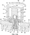
- FIG. 11B shows a sectional view of the pressure-setting regulator 400 having the knob rotated to increase the pressure of an outlet gas stream.
- the regulator knob 410 is rotated in an increasing flow direction 590 the poppet 437 is moved away from the poppet seat 438.
- flow from compressed gas stream 510 is allowed to flow through the valve channel 439 to become an outlet gas stream 560.
- the outlet gas stream 560 has a pressure which is positively controlled to achieve a set point value 425 of outlet pressure 550.
- the rotation of the regulator knob 410 can move the poppet 437 away from the poppet seat 438 and allow flow from compressed gas stream 510 to flow through the valve channel 439 to become an outlet gas stream 560 having a pressure which is positively controlled to achieve a set point value 425 of the outlet pressure 550.
- moving the poppet 437 away from the poppet seat 438 decreases the pressure drop across the valve 490, increases the flow rate, and increases the outlet pressure 550.
- FIG. 11B shows that from a set position of the regulator knob 410 which maintains the flow at the set outlet pressure 550 can be manually rotated in the increasing flow direction 590, or the decreasing flow direction 595, shown as a dashed arrow, at an operator's discretion.
- the regulator knob 410 can be manually rotated in the increasing flow direction 590 to any outlet pressure 550 from a minimum value to a maximum value, or any outlet pressure 550 in between these set points.
- the regulator knob 410 can also be manually rotated in the decreasing flow direction 595 to any outlet pressure 550 from a maximum value to a minimum value or any outlet pressure 550 in between these set points.
- the pressure of an outlet gas stream which is flowing is also reduced.
- poppet 437 is moved toward poppet seat 438 and the flow rate from compressed gas stream 510 through the valve channel 439 is decreased, and the flow rate which becomes outlet gas stream 560 is also decreased.
- the poppet 437 is moved toward poppet seat 438 which increases the pressure drop across the valve 490, decreases the flow rate and decreases the outlet pressure 550 during flow.
- FIG. 11C shows a sectional view of the pressure-setting regulator having the knob rotated to a set outlet pressure 550 and regulating the flow of an outlet gas stream.
- FIG. 11C shows the pressure-setting regulator 400 maintaining the set point value 425 of outlet pressure 550, such as shown for example in FIG. 10C .
- the pressure-setting regulator 400 can be rotated in the decreasing flow direction 595 to a "no flow” position (as shown in FIG. 10A ), and the flow of the outlet gas stream 560 can be reduced to zero.
- the regulator knob 410 is rotated to a "no flow” position the valve poppet 437 to be seated in poppet seat 438 ( FIG. 11A ) and the valve configuration can be closed not allowing any portion of compressor gas stream to pass.
Landscapes
- Engineering & Computer Science (AREA)
- General Engineering & Computer Science (AREA)
- Mechanical Engineering (AREA)
- Control Of Fluid Pressure (AREA)
Abstract
Description
- The invention relates to a pressure regulator.
- Manually setting the outlet pressure of a pressure regulator is an inefficient, clumsy and empirical process that requires a feedback system in which an operator visually monitors an outlet pressure gauge and adjusts and tweaks the regulator pressure drop until a final outlet pressure is eventually achieved. This approach is time consuming, inaccurate, and allows for an operator to overshoot or undershoot a desired outlet pressure during the process. Such error can cause operational difficulties, as well as preventing operation at the outlet pressure desired. A strong need exists for a new control system for manually setting the outlet pressure of pressure regulators.
- An embodiment of the present invention is directed to an air compressor that eliminates the regulator pressure gauge and allows the regulator to manually be set to a predetermined pressure.
- In an embodiment, a pressure regulator can have a scale indicating a number of outlet pressures which can be set as a selected outlet pressure of a gas exiting the pressure regulator. A regulator knob can be adapted to be rotated manually to a selected outlet pressure chosen from the number of outlet pressures. A regulator spring can be used that at least in part controls a valve that regulates a flow of the gas. The regulator knob can be adapted to change a spring compression of the regulator spring when the regulator knob is manually rotated to set the selected outlet pressure of the gas.
- In an embodiment, rotation of the regulator knob to the selected outlet pressure, as well as setting a selected outlet pressure, can be free of a feedback control mechanism. The selected outlet pressure can be set by the regulator knob to a value selected on the scale and the pressure regulator can be configured to produce an outlet pressure free of reference to an outlet pressure gauge.
- The scale can be of a variety of configurations. For example, the scale can be configured to be generally coaxial with the circumference of the regulator knob. In an embodiment, the scale can be configured to be generally coaxial with the circumference of the regulator knob and can indicate a plurality of outlet pressures which can be selected and which have one or more of the plurality of outlet pressures in a range of from 25 psig to 250 psig, or higher.
- The regulator knob can also have of a variety of designs. In one embodiment, the regulator knob can have single-turn coarse grooves which slideably engage single-turn coarse threads which project from a portion of a regulator body, such as a control cylinder. Optionally, the regulator knob can have an indicium which can be aligned with a portion of the scale to set the selected outlet pressure. In an embodiment, the indicium can be an arrow, such as a set point arrow, which can be pointed to a pressure indicated by the scale to set a selected outlet pressure.
- The rotation of the regulator knob and the indication of its position can have a variety of mechanisms, in an embodiment the regulator knob can be ratcheted when rotated to cause an alignment of a portion of the regulator knob to a portion of the scale to set the selected outlet pressure.
- In an embodiment, a pressure control system can have the pressure regulator which can have a regulator knob which can be rotated to control an outlet pressure of a gas exiting the pressure regulator. The pressure control system can also have the scale configured proximate to the regulator knob and indicating a plurality of outlet pressure values one of which can be selected as an outlet set pressure; an indicium mounted on and moved by the regulator knob, the indicium proximate to an outlet pressure value that is selected as an outlet set pressure. In an embodiment, the outlet set pressure can be selected by rotating the regulator knob to control the outlet pressure of the gas exiting the regulator at a desired outlet set pressure.
- In an embodiment, the pressure control system can have a control cylinder can have a single-turn course thread projecting from a portion of a regulator body. The single-turn course thread can be configured to slideably engage the regulator knob. The pressure control system can use a regulator knob which is a single-turn regulator knob.
- The pressure control system can control the outlet pressure to within 15 percent, or 10 percent, or closer, of an outlet set pressure when the regulator knob remains in a fixed position corresponding to a selected outlet pressure. In an embodiment, the pressure control system can be configured to indicate an outlet pressure midpoint when the regulator knob is rotated to a point that is located at about one-half of its rotational range.
- A compressor can have the pressure-setting regulator and/or the pressure control system which uses the pressure-setting regulator. In an embodiment, a compressor for producing a compressed gas can have the pressure regulator, a scale indicating a plurality of outlet pressures which can be set as a selected outlet pressure of a gas exiting the regulator and a regulator knob adapted to be manually rotated to set the selected outlet pressure from the plurality of outlet pressures of the scale. A regulator spring can at least in part control a valve that regulates a flow of the gas of the pressure-setting regulator. The regulator knob can be adapted to change a spring compression of the regulator spring when the regulator knob is manually rotated to set the selected outlet pressure of the gas. In an embodiment, the scale can be configured proximate to the regulator knob.
- In an embodiment, a positive control method of pressure regulation can use the pressure-setting regulator. A method of controlling the regulator outlet pressure can have the steps of: providing a regulator having a single-turn regulator knob which has an indicium adapted to indicated a portion of the scale; providing the scale configured proximate to the single-turn regulator knob and having a plurality of outlet pressures; rotating the single-turn regulator knob such that the indicium indicates an outlet pressure which is an outlet pressure set point; and in which the rotating of the single-turn regulator knob changes the pressure exerted by a regulator spring which changes the differential pressure of the regulator to change the outlet pressure. In an embodiment, the method of controlling regulator outlet pressure can control the controlling the outlet pressure within 20 percent of the outlet pressure set point.
- In an embodiment, the pressure-setting regulator can be set to an outlet pressure by rotating the regulator knob such that the indicium, such as the set point arrow, is proximate to a selected outlet pressure. In an embodiment, the regulator knob can be calibrated to position the indicium, such as an arrow or other mark, such that it is configured at the mid-range of the single-turn regulator knob rotational range. In another embodiment, the pressure-setting regulator can be calibrated to achieve a minimum variance in the outlet pressure when the indicium is at a position within 45 degrees of the rotational mid-point of the regulator knob.
- The present invention in its several aspects and embodiments solves the problems discussed above and significantly advances the technology of pressure regulators. The present invention can become more fully understood from the detailed description and the accompanying drawings, wherein:
-
FIG. 1 shows an existing air compressor employing a feedback control system having a regulator and an outlet pressure gauge; -
FIG. 2 shows a perspective view of a compressor assembly having a pressure-setting regulator; -
FIG. 3 shows a perspective view of the mechanical design of the compressor assembly having the pressure-setting regulator without the housing; -
FIG. 4 shows a pump-side view of the mechanical design of the compressor assembly having the pressure-setting regulator without the housing; -
FIG. 5A shows a control cylinder with a fine pitch thread; -
FIG. 5B shows the control cylinder with a coarse pitch thread; -
FIG. 6A shows a regulator knob with grooves corresponding to the fine pitch thread; -
FIG. 6B shows the regulator knob with grooves corresponding to the coarse pitch thread; -
FIG. 7 shows a sectional view of the pressure-setting regulator; -
FIG. 8 shows a dashboard having an inlet pressure gauge and the pressure-setting regulator with an example scale of outlet set pressure options; -
FIG. 9 shows a dashboard having an inlet pressure gauge and a multi-turn configuration of the pressure-setting regulator; -
FIG. 10A shows the knob bearing an indicium at a first position; -
FIG. 10B shows the knob bearing an indicium being rotated to a second position; -
FIG. 10C shows the knob bearing an indicium at a third position; -
FIG. 10D shows the knob bearing an indicium being rotated to a fourth position; -
FIG. 11A shows a sectional view of the pressure-setting regulator in a closed configuration; -
FIG. 11B shows a sectional view of the pressure-setting regulator having the knob rotatable to increase and decrease the pressure of an outlet gas stream; and -
FIG. 11C shows a sectional view of the pressure-setting regulator having the knob rotated to a set outlet pressure and regulating the flow of an outlet gas stream. - Herein, like reference numbers in one figure refer to like reference numbers in another figure.
- The invention relates to the many and varied embodiments of a positive control regulator, pressure regulation system and to methods for regulating outlet gas pressure from a compressor. The pressure regulation system can be used with a compressor assembly which can compress air, or a gas, or gas mixtures. The compressor can compress one or more gases, inert gases, or mixed gas compositions.
-
FIG. 1 shows an existing air compressor employing a feedback control system having a regulator and an outlet pressure gauge. As shown inFigure 1 , existing air compressors have a manifold including a regulator for increasing or decreasing the pressure output to a connected power tool. The regulator can be in the form of an old-style regulator knob 121 that is connected to a pressure regulator valve that opens and closes to admit and obstruct, respectively, the flow of pressurized air into the power tool. The regulator is connected to a regulatoroutlet pressure gauge 122 that measures the regulator pressure and provides an indication of the measurement in a form such as a dial that can be read by the user. When the regulator knob is turned, there is a delay between setting the regulator pressure and the pressure gauge readout until the pressure in the system catches up to the regulator pressure or decreases to the regulator pressure selected by the user. In addition, it is necessary for the user to perform incremental regulator knob rotations, clockwise and counterclockwise, in order to adjust the regulator until the regulatoroutlet pressure gauge 122 reads the desired pressure. -
FIG. 2 shows a perspective view of acompressor assembly 20. In an embodiment, thecompressor assembly 20 can compress air, or can compress one or more gases, or gas mixtures. Thecompressor assembly 20 can be portable and can have ahandle 29, which optionally can be a portion ofcompressor body 13. - The definition of "air" herein is intended to be very broad. The term "air" includes breathable air, ambient air, treated air, conditioned air, clean room air, cooled air, heated air, non-flammable oxygen containing gas, filtered air, purified air, contaminated air, air with particulates solids or water, air from bone dry (i.e. 0.00 humidity) air to air which is supersaturated with water, as well as any other type of air present in an environment in which a gas (e.g. air) compressor can be used. It is intended that cooling gases which are not air are encompassed by this disclosure. For non-limiting example, a cooling gas can be nitrogen, can comprise a gas mixture, can comprise nitrogen, can comprise oxygen (in a safe concentration), can comprise carbon dioxide, can comprise one inert gas or a plurality of inert gases, or comprise a mixture of gases.
- In an example embodiment, the
compressor assembly 20 can have a pressure-settingregulator 400 configured at least in part within ahousing 21. The compressor assembly includes atank pressure gauge 325, aregulator knob 410 and atool connect member 10 located on a face of thehousing 21. An ON/OFF switch 11 can be located on a front portion of thehousing 21. Theregulator knob 410 is the control which controls the pressure-settingregulator 400 that is set within a desired air outlet pressure guide. Theregulator knob 410 that is rotatable to a position that corresponds to the desired air output pressure to the tool. The desired air outlet pressure guide, which can be ascale 500, is located on adashboard 300 on the face of thehousing 21 to be readable by an operator. The outlet pressure guide can optionally be in the form of a label. Alternatively, the outlet pressure guide can be integrally molded with the manifold, or etched thereon. Thereby, the regulatoroutlet pressure gauge 122 of the prior art shown inFIG. 1 is no longer needed. As a result of the embodiments of the present invention, users can rotate the regulator knob to set the desired outlet pressure, and not have to wait for a pressure gauge to catch up to the regulator set pressure and/or perform back and forth adjustments. - As shown, for example in
FIGS 2 ,8 ,9 and10A-D , thescale 500 can be configured to be generally coaxial with the circumference of theregulator knob 410. Such a generally coaxial configuration can allow an indicium of theregulator knob 410, such asset point arrow 420, to be aligned with, or positioned proximate to, a value of outlet pressure on thescale 500. In this embodiment, theregulator knob 410 that has an indicium, such asset point arrow 420, can be turned to align with or point to a desiredoutlet pressure 550 which by such alignment positively sets that anoutlet pressure 550 which is desired, and positively controls and maintains the desired outlet pressure. -
FIG. 2 illustrates an example embodiment of the air compressor in which the tool connectmember 10 is located on theintake fan side 14 of thehousing 21. - In an embodiment, the
compressor assembly 20 can have a weight between 15 lbs and 100 lbs. In an embodiment, a portable embodiment of thecompressor assembly 20 can have of weight between 10 lbs and 50 lbs, such as 10 lbs to 30 lbs, or 15 lbs to 40 lbs. - In an embodiment, the
housing 21 can have afront housing 161 and arear housing 170 and a plurality ofintake ports 182. The compressor assembly can be cooled by air flow provided by afan 200 the plurality ofintake ports 182. - Power can be supplied to a
motor 33 of the compressor assembly through apower cord 5 extending through thehousing 21. In an embodiment, thecompressor assembly 20 can comprise one or more of a cord holder member, such as afirst cord wrap 6 and asecond cord wrap 7. - In an embodiment, the
power switch 11 can be used to change the operating state of thecompressor assembly 20 at least from an "on" to an "off" state, and vice versa. In the "on" state, the compressor can be in a compressing state (also herein as a "pumping state") in which it is compressing air, or a gas, or a plurality of gases, or a gas mixture. - In an embodiment, other operating modes can be engaged by the
power switch 11 or a compressor control system, e.g. a standby mode, or a power save mode. In an embodiment, thedashboard 300 can provide an operator-accessible location for connections, gauges and valves which can be connected to a manifold 303 (FIG. 3 ). In an embodiment, thedashboard 300 can provide an operator access in a non-limiting example to the tool connectmember 10, the pressure-settingregulator 400 and thetank pressure gauge 325. In an embodiment, a compressed gas outlet line, hose or other device to receive compressed gas can be connected the tool connectmember 10. - A plurality of
intake ports 182 can be formed in thehousing 21 proximate to thefan 200 and a plurality of exhaust ports 31 (not shown) can be formed in thehousing 21 proximate to the pump. The total cross-sectional open area of theintake ports 182. In an embodiment, the cooling gas employed to cool thecompressor assembly 20 and its components can be air, which optionally can be taken in from the environment in which thecompressor assembly 20 is placed. The cooling gas can be exhausted from thecompressor assembly 20 through a plurality of exhaust ports (not shown). -
FIG. 3 illustrates thecompressor assembly 20 with a portion of thehousing 21 removed and showing the internal components of the compressor assembly. Thepump assembly 25 compresses a gas, air or gas mixture. In an embodiment, thepump assembly 25 can be powered by the motor 33 (e.g.FIG. 3 ). The manifold 303 is shown having the pressure-settingregulator 400 and being free of an outlet pressure gauge. - Numeric values and ranges herein, unless otherwise stated, also are intended to have associated with them a tolerance and to account for variances of design and manufacturing, and/or operational and performance fluctuations. Thus, a number disclosed herein is intended to disclose values "about" that number. For example, a value X is also intended to be understood as "about X". Likewise, a range of Y-Z, is also intended to be understood as within a range of from "about Y-about Z". Unless otherwise stated, significant digits disclosed for a number are not intended to make the number an exact limiting value. Variance and tolerance, as well as operational or performance fluctuations, are an expected aspect of mechanical design and the numbers disclosed herein are intended to be construed to allow for such factors (in non-limiting e.g., ± 10 percent of a given value). This disclosure is to be broadly construed. Likewise, the claims are to be broadly construed in their recitations of numbers and ranges.
- The
compressed gas tank 150 can operate at a pressure in a range of at least from ambient pressure, e.g. 14.7 psig to 3000 psig ("psig" is the unit lbf/in^2 gauge), or greater. In an embodiment, thecompressed gas tank 150 can operate at 200 psig. In an embodiment, thecompressed gas tank 150 can operate at 150 psig. - In an embodiment, the pressure-setting
regulator 400 can use a pressure regulating valve. In an embodiment, excess air pressure can be vented to atmosphere through apressure relief valve 199, such as a spring loaded safety valve. In an embodiment, thepump assembly 25 and thecompressed gas tank 150 can be connected to a frame 111 (FIG. 3 ). - In an embodiment, the compressor has a pressure regulated on/off switch which can stop the
pump assembly 25 when a specified compressed gas tank pressure is obtained. Activation of thepump assembly 25 can occur at a pressure in a wide range of set operating pressure, e.g. 25 percent to 99.5 percent of specified compressed gas tank operating pressure. The specified compressed gas tank operating pressure can be in a range from 25 psig to 3000 psig. In an embodiment, the specifiedcompressed gas tank 150 pressure can be 50 psig, 75 psig, 100 psig, 150 psig, 200 psig, 250 psig, 300 psig, 500 psig, 1000 psig, 2000 psig, 3000 psig, or greater than or less than, or a value in between these example numbers. -
FIG. 4 shows a pump-side view of components of thepump assembly 25.FIG. 4 shows the mechanical design of thecompressor assembly 20 having the pressure-setting regulator without thehousing 21. In an embodiment, a feed air for compression can be fed to thecylinder head 61 of thepump assembly 25. The feed air can be compressed in apump cylinder 60 by apiston 63 to produce a compressed gas stream 510 (FIG. 7 ) from thecylinder head 61 and can pass through a compressedgas outlet line 145 to enter thecompressed gas tank 150. - Depending upon the compressed gas output specifications, such as output flow ranges and outlet pressure ranges, of the
compressor assembly 20, themotor 33 can operate at a motor speed between 1,000 rpm and 30,000 rpm. In an embodiment, themotor 33 can operate at a speed in a range of between 7,500 rpm and 12,000 rpm. In further embodiments, themotor 33 can operate at e.g. 11,252 rpm, or 11,000 rpm; or 10,000 rpm; or 9,000 rpm; or 7,500 rpm; or 6,000 rpm; or 5,000 rpm. - In an embodiment, the motor can be a non-synchronous universal motor rated, for example, at 1/2 horsepower, at 3/4 horsepower, at 1 horsepower, at 2 horsepower, at 5 horseposer or greater. In an embodiment, the motor can be a synchronous motor. The
compressor assembly 20 can accommodate a variety of types ofmotor 33. The pressure-settingregulator 400 can be used in large-scale industrial equipment and compressors, as well as in portable equipment and compressors. - The
pump assembly 25 can have the components which are attached to the motor and/or which serve to compress a gas; which in a non-limiting example can comprise thefan 200, themotor 33, and apump 59, with apump arm 91. - The
pump assembly 25 can have thepump 59, such as a "gas pump" or an "air pump" that includes apiston 63, apump cylinder 60, in which apiston 63 reciprocates and a connectingrod 69. The pump further includes apulley 66, adrive belt 65 and driving mechanism driven bymotor 33. The connectingrod 69 can connect to thepiston 63 which can move inside of thepump cylinder 60. The motor can be a high speed universal motor, or other type of motor. Thepiston 63 can compress a gas in thepump cylinder 60 pumping the compressed gas through the valve plate assembly 62 into thecylinder head 61 and then out through a compressed gas outlet port 782 through anoutlet line 145 and into thecompressed gas tank 150. - The
pulley 66 and asprocket 49, can in part drive thedrive belt 65, and can be sized to achieve reduced pump speeds, which can correspond to reciprocation rates and/or a piston speed at which thepiston 63 is reciprocated. - In an embodiment shown in
FIG. 5A , acontrol cylinder 417 of the pressure-settingregulator 400 can have afine pitch thread 412 and a finepitch thread angle 414. The finepitch thread angle 414 can be less than 1.5 degrees, such as 1.17 degrees. In an embodiment, thecontrol cylinder 417 can have greater than 10 threads per inch of thefine pitch thread 412, such as 13 threads per inch. Theregulator knob 410 can be a single-turn knob or a multi-turn knob. -
FIG. 5B shows the control cylinder with a coarse pitch thread. In an embodiment, the single-turn embodiment, shown inFIG. 5B thecontrol cylinder 417 can have acoarse pitch thread 413 which can have a coarsepitch thread angle 415. The coarsepitch thread angle 415 can be greater than 1.5 degrees, such as 3.79 degrees. In an embodiment, thecontrol cylinder 417 can have fewer than 10 threads per inch of thecoarse pitch thread 413, such as 4 threads per inch. - The pitch thread angle, whether the fine
pitch thread angle 414, or the coarsepitch thread angle 415 can achieve a desired angle of rotation in which the knob is rotated to achieve aset outlet pressure 550, or to achieve any number of turns or partial turns of a knob to achieve aset outlet pressure 550. -
FIG. 6A shows a first example of aregulator knob 410 which has a finepitch thread grooves 416 corresponding to the fine pitch thread which can engage thefine pitch thread 412 ofFIG. 5A . The finepitch thread groove 416 can have a groove angle and a number of turns to correspond to thefine pitch thread 412 to which it is engaged. -
FIG. 6B shows a second example of aregulator knob 410 which has a coarsepitch thread grooves 419 corresponding to the coarse pitch thread which can engage thecoarse pitch thread 415 ofFIG. 5B . The coarsepitch thread groove 419 can have a groove angle and a number of turns to correspond to thecoarse pitch thread 415 to which it is engaged. -
FIG. 7 shows a sectional view of the pressure-settingregulator 400. As shown inFIG. 7 , the combined regulator includes apiston 432 that is slideably disposed within thecontrol cylinder 417. Thepiston 432 moves relative to thecontrol cylinder 417, such as in an up and down motion, when the user rotates theregulator knob 410. For example, thepiston 432 can move downward when the user rotates theregulator knob 410 in a clockwise direction to compress theregulator spring 430 thereby increasing the outlet pressure 550 (FIG. 11A ). Conversely, the piston moves up when the user rotates the knob in a counterclockwise direction to release theregulator spring 430, raise the piston and reduce theoutlet pressure 550. -
FIG. 7 shows as an example, theregulator knob 410 having the coarsepitch thread groove 419 rotatably engaged with thecoarse pitch threads 413 of thecontrol cylinder 417. Aregulator spring 430 can be housed in aspring chamber 429 and can extend between a portion of theknob driver top 428 and a portion of thepiston 432. In an embodiment, theregulator spring 430 is held in position at least in part by aspring boss 431. - The
regulator spring 430 imparts pressure from theregulator knob 410 to thepiston 432. In the example embodiment ofFIG. 7 , thepiston 432 has avalve stem 433 which can project though avalve channel 439. The valve stem 433 can exert pressure on avalve poppet 437 which can be engaged with avalve spring 440. - The pressure-setting
regulator 400 regulates the flow of a compressed gas and creates a pressure drop between the compressed gas pressure in thecompressed gas tank 150 and/or the manifold 303 and/or theregulator inlet 509, such asinlet pressure 501, and aregulator outlet 549 having theoutlet pressure 550.FIG. 7 shows an embodiment in which acompressed gas stream 510 enters aregulator inlet 509 at aninlet pressure 501. Thecompressed gas stream 510 at aninlet pressure 501 can be blocked by the valve mechanism when it is closed, as shown inFIGS 11A-11C , or can flow through thevalve channel 439 to become anoutlet gas stream 560 having anoutlet pressure 550 and which exits the pressure-settingregulator 400 throughregulator outlet 549. -
FIG. 8 shows adashboard 300 having aninlet pressure gauge 495 and the pressure-setting regulator with an example scale of outlet set pressure options. In this example, the letter "A" represents a lowset outlet pressure 600, or zero set outlet pressure, point on the scale. The letter "B" represents amidpoint outlet pressure 610. The letter "C" represents ahigh outlet pressure 620. The lowset outlet pressure 600, themidpoint outlet pressure 610 and thehigh outlet pressure 620 can be set to accommodate a desired pressure range, such as 0 psig to 150 psig (FIG. 10A ), or 0 psig to 250 psig, or 0 psig to 300 psig, or 0 psig to 500 psig, or other range. -
FIG. 8 also shows theinlet pressure gauge 495 which measures theinlet pressure 501 to the pressure-settingregulator 400. - Optionally, the
scale 500 can be set for a single-turn configuration in which a single, or partial, rotation of theregulator knob 410 can be applied to allow a user to select any outlet pressure on thescale 500. - The thread angle and/or number of threads per inch can be set to accommodate a desired range of pressures to achieve a single-turn functionality for a desired range of pressures and/or
scale 500. -
FIG. 9 shows adashboard 300 having aninlet pressure gauge 495 and a multi-turn configuration of the pressure-settingregulator 400. In a multi-turn configuration, thescale 500 can optionally be configured at different levels concentrically around theregulator knob 410. In a non-limiting example, thescale 500 has two levels concentrically arranged around theregulator knob 410 with the first indicating set outlet pressure values from 0 to 190 psig and the second level indicating set outlet pressure values from 200 psig to 350 psig. As shown by multi-turn increasingflow arrow 593, theregulator knob 410 can be turned greater than 360 degrees, such as 720 degrees to positively control theoutlet pressure 550 to theset point value 425 chosen selected by positioning thearrowhead 422 or setpoint arrow 420 proximate to a selectedset point value 425. - In single-turn and multi-turn applications, the
regulator knob 410 can be reversibly turned, for example in one direction to increase gas flow and in the reverse direction to decrease gas flow. -
FIG. 10A shows theregulator knob 410 bearing an indicium at a first position. The nonlimiting example ofFIG. 10A is a single-turn embodiment in which an operator can reversibly rotate theregulator knob 410 to set a desiredoutlet pressure 550 by aligning thearrowhead 422 of the set point arrow to a set point pressure in the range of thescale 500. - The
dashboard 300 of the example ofFIG. 10A shows the pressure-settingregulator 400 with a numeric scale of outlet set pressures. Optionally, thescale 500 of the set point values 425 of the outlet pressure is shown on thedashboard 300 and configured concentrically around at least a portion of theregulator knob 410. As shown inFIG. 8 and the series ofFIGS 10A-10D , theregulator knob 410 can be rotated to select theset point value 425 ofoutlet pressure 550 by aligning thearrowhead 422 proximate to theset point value 425 selected by an operator at theoutlet pressure 550 desired. - In the embodiment of
FIG. 10A , theregulator knob 410 is a single-turn knob which can be smoothly rotated to select any value whether marked on the scale or between markings between a minimum outlet pressure value and a maximum outlet pressure value, which for example can between 0 psig to 150 psig, or other range as desired. - In
FIG. 10A , the pressure-settingregulator 400 is in a "no flow" position in which the set point value is zero, theoutlet gas stream 560 is zero, and theoutlet pressure 550 not affected by theinlet pressure 501. When the pressure-settingregulator 400 does not allow flow, theoutlet pressure 550 can be ambient as no flow is passing through the pressure-settingregulator 400. In this example, the zero pressure setting is the low point of the pressure range of thescale 500. The configuration is shown, for example, inFIGS 10A-10D . - The
scale 500 shown inFIG. 10A indicates set point values ofoutlet pressure 550 from 0 psig to 150 psig. By rotating theregulator knob 410 any value between 0 psig to 150 psig can be set at theoutlet pressure 550 by the positive manual control of the operator turning the knob to select a givenset point value 425 ofoutlet pressure 550 by aligning thearrowhead 422 proximate to theset point value 425 selected. - In an embodiment, the pressure-setting
regulator 400 can be calibrated for exacting performance in achieving and maintaining aset outlet pressure 550. A calibrated pressure gauge can be attached to a test manifold having an attached uncalibrated pressure-setting regulator. The uncalibrated pressure-settingregulator 400 can be set to a mid-range outlet pressure, such as 100 psig in a non-limiting example. In a calibration step, when the uncalibrated pressure-settingregulator 400 is set to a mid-range outlet pressure, an indicium, such as a label bearing aset point arrow 420, can be placed on the knob driver top 428 (FIG. 10A ) having thearrowhead 422 pointing to the mid-range outlet pressure, such as 100 psig, resulting in a calibrated pressure-settingregulator 400 calibrated to the mid-range outlet pressure. - In an embodiment, the mid-range outlet pressure can occur at a one-half of the rotational range of the regulator knob, and the scale can be configured to have the mid-range outlet pressure value positioned at the point of one-half of the rotation al range of the regulator knob. This allows the indicium to be configured on the regulator knob such that at the point in which the one-half of the rotational range of the regulator knob the indicium is aligned with, or is proximate to, the mid-range outlet pressure value of the scale, for example an
arrowhead 422 pointing to the mid-range outlet pressure value of the scale. -
FIG. 10B shows the knob bearing an indicium being rotated to a second position.FIG. 10B shows theregulator knob 410 being turned in the increasingflow direction 590 to select an outlet pressure setpoint 425 of 25 psig. When rotated to the second position, the valve configuration of pressure-settingregulator 400 is open to achieve anoutlet gas stream 560 flow having theoutlet pressure 550 of 25 psig. The configuration having a flow of theoutlet gas stream 560 is shown, for example, inFIGS 11A-11C . -
FIG. 10C shows theregulator knob 410 having aset point arrow 420 at a third position.FIG. 10C shows the knob positively controlling the outlet pressing 550 to theset point value 425 of 75 psig.FIG. 10C shows the pressure-settingregulator 400 maintaining theoutlet pressure 550 at 75 psig. In the example ofFIG. 10C , the 75 psig value is the mid-range set point ofoutlet pressure 550 of the pressure range of thescale 500. -
FIG. 10D shows the knob bearing an indicium, such asset point arrow 420, being rotated to a fourth position in the increasingflow direction 590 to select an outlet pressure setpoint 425 of 150 psig, which is the maximum outlet pressure shown in the example ofFIG. 10D . The valve configuration of pressure-settingregulator 400 opens to achieve anoutlet gas stream 560 flow having theoutlet pressure 550 of 150 psig. In this example, the 150 psig value is the high end set point ofoutlet pressure 550 of the pressure range of thescale 500. - Optionally, the high-end set point of
outlet pressure 550 of thescale 500 can be a maximum output pressure possible from the compressor. In another embodiment, the high-end set point of outlet pressure of thescale 500 can be limited to less than the maximum outlet pressure from the compressor. The limit on theoutlet pressure 550 can be achieved by the design of the control knob threads or the knob thread grooves. Alternately, the compressor can be mechanically limited to the high-end set point ofoutlet pressure 550 of thescale 500. - The rotation of the
regulator knob 410 is reversible and theregulator knob 410 can be turned in either the increasingflow direction 590, or the decreasing flow direction 595 (FIG. 11A ), at an operator's discretion. Thus, an operator can change theoutlet pressure 550 from a selected value to a different value by rotating the knob in either the increasingflow direction 590 or the decreasingflow direction 595. - In an example the
regulator knob 410 can be rotated from a set pressure, such as 150 psig, by rotating theregulator knob 410 in the decreasingflow direction 595 to the first position in which the pressure-settingregulator 400 is in an "no flow" position in which the set point value is zero, theoutlet gas stream 560 is zero. -
FIG. 11A shows a sectional view of the pressure-settingregulator 400 in a closed configuration. In the example ofFIG. 11A , the pressure-settingregulator 400 is in a "no flow" position (FIG. 10A ) in which the set point value is zero, the flow of theoutlet gas stream 560 is zero, and theoutlet pressure 550 not affected by theinlet pressure 501. As shown inFIG. 11A , theregulator knob 410 is configured such that thevalve poppet 437 is seated inpoppet seat 438 and the valve configuration is closed and does not allow any portion of compressor gas stream to pass. - In an embodiment, the pressure-setting
regulator 400 can be self-relieving and can respond to maintain a constant set outlet pressure when the set pressure is changed from a higher set outlet pressure to a lower set outlet pressure. In another example, the pressure-settingregulator 400 can be non-relieving. However, in the non-relieving embodiment the outlet pressure will reset from a higher outlet pressure to a lower outlet pressure after turning the regulator knob to set the lower outlet pressure and once the residual higher pressure gas is released from thevalve channel 439 by use of a tool or other means. In either the relieving or non-relieving embodiments, the pressure-setting regulator valve configuration will respond to maintain a constant outlet pressure as compressed gas is used. - In the embodiment of
FIG. 11A , rotating theregulator knob 410 in the increasingflow direction 590 can tighten theregulator knob 410 in a tighteningdirection 592. In the reverse, as shown by dashed line type, rotating theregulator knob 410 in the decreasingflow direction 595 can loosen theregulator knob 410 in theloosening direction 598. -
FIG. 11B shows a sectional view of the pressure-settingregulator 400 having the knob rotated to increase the pressure of an outlet gas stream. When theregulator knob 410 is rotated in an increasingflow direction 590 thepoppet 437 is moved away from thepoppet seat 438. As a result, flow fromcompressed gas stream 510 is allowed to flow through thevalve channel 439 to become anoutlet gas stream 560. Theoutlet gas stream 560 has a pressure which is positively controlled to achieve aset point value 425 ofoutlet pressure 550. For example, the rotation of theregulator knob 410, as shown for example in each ofFIGS 10A-10D , can move thepoppet 437 away from thepoppet seat 438 and allow flow fromcompressed gas stream 510 to flow through thevalve channel 439 to become anoutlet gas stream 560 having a pressure which is positively controlled to achieve aset point value 425 of theoutlet pressure 550. In the example ofFIG. 11B moving thepoppet 437 away from thepoppet seat 438 decreases the pressure drop across thevalve 490, increases the flow rate, and increases theoutlet pressure 550. -
FIG. 11B shows that from a set position of theregulator knob 410 which maintains the flow at theset outlet pressure 550 can be manually rotated in the increasingflow direction 590, or the decreasingflow direction 595, shown as a dashed arrow, at an operator's discretion. Theregulator knob 410 can be manually rotated in the increasingflow direction 590 to anyoutlet pressure 550 from a minimum value to a maximum value, or anyoutlet pressure 550 in between these set points. Theregulator knob 410 can also be manually rotated in the decreasingflow direction 595 to anyoutlet pressure 550 from a maximum value to a minimum value or anyoutlet pressure 550 in between these set points. - When the
regulator knob 410 is rotated in the decreasingflow direction 595, the pressure of an outlet gas stream which is flowing is also reduced. When theregulator knob 410 is rotated in decreasingflow direction 595,poppet 437 is moved towardpoppet seat 438 and the flow rate fromcompressed gas stream 510 through thevalve channel 439 is decreased, and the flow rate which becomesoutlet gas stream 560 is also decreased. When theregulator knob 410 is rotated in decreasingflow direction 595, for example in the counterclockwise direction, thepoppet 437 is moved towardpoppet seat 438 which increases the pressure drop across thevalve 490, decreases the flow rate and decreases theoutlet pressure 550 during flow. -
FIG. 11C shows a sectional view of the pressure-setting regulator having the knob rotated to aset outlet pressure 550 and regulating the flow of an outlet gas stream.FIG. 11C shows the pressure-settingregulator 400 maintaining theset point value 425 ofoutlet pressure 550, such as shown for example inFIG. 10C . - From any set outlet pressure, the pressure-setting
regulator 400 can be rotated in the decreasingflow direction 595 to a "no flow" position (as shown inFIG. 10A ), and the flow of theoutlet gas stream 560 can be reduced to zero. When theregulator knob 410 is rotated to a "no flow" position thevalve poppet 437 to be seated in poppet seat 438 (FIG. 11A ) and the valve configuration can be closed not allowing any portion of compressor gas stream to pass. - The scope of this disclosure is to be broadly construed. It is intended that this disclosure disclose equivalents, means, systems and methods to achieve the devices, designs, operations, control systems, controls, activities, mechanical actions, fluid dynamics and results disclosed herein. For each mechanical element or mechanism disclosed, it is intended that this disclosure also encompasses within the scope of its disclosure and teaches equivalents, means, systems and methods for practicing the many aspects, mechanisms and devices disclosed herein. Additionally, this disclosure regards a pressure regulator and its many aspects, features and elements. Such an apparatus can be dynamic in its use and operation. This disclosure is intended to encompass the equivalents, means, systems and methods of the use of the compressor assembly and its many aspects consistent with the description and spirit of the apparatus, means, methods, functions and operations disclosed herein. The claims of this application are likewise to be broadly construed.
- The description of the inventions herein in their many embodiments is merely exemplary in nature and, thus, variations that do not depart from the gist of the invention are intended to be within the scope of the invention and the disclosure herein. Such variations are not to be regarded as a departure from the spirit and scope of the invention.
- It will be appreciated that various modifications and changes can be made to the above described embodiments of the compressor assembly as disclosed herein without departing from the spirit and the scope of the following claims.
Claims (15)
- A pressure regulator, comprising:a scale indicating a plurality of outlet pressures which can be set as a selected outlet pressure of a gas exiting the pressure regulator;a regulator knob adapted to be manually rotated to a selected outlet pressure from the plurality of outlet pressures; anda regulator spring that at least in part controls a valve that regulates a flow of said gas,wherein the regulator knob is adapted to change a spring compression of the regulator spring when the regulator knob is manually rotated to set the selected outlet pressure of the gas.
- The pressure regulator of claim 1, wherein rotation of the regulator knob to the selected outlet pressure is free of a feedback control mechanism.
- The pressure regulator of claim 1, wherein the selected outlet pressure is set by the regulator knob to a value selected on the scale, the pressure regulator being configured to produce an outlet pressure free of reference to an outlet pressure gauge.
- The pressure regulator of claim 1, wherein the scale is configured to be generally coaxial with the circumference of the regulator knob.
- The pressure regulator of claim 1, wherein the scale is configured to be generally coaxial with the circumference of the regulator knob and indicates a plurality of outlet pressures which can be selected and which have one or more of the plurality of outlet pressures in a range of from 25 psig to 250 psig.
- The pressure regulator of claim 1, wherein the regulator knob has single-turn coarse grooves which slideably engage single-turn coarse threads which project from a portion of a regulator body.
- The pressure regulator of claim 1, wherein the regulator knob further comprises an indicium which can be aligned with a portion of the scale to set the selected outlet pressure.
- The pressure regulator of claim 1, wherein the regulator knob further comprises an arrow which can be pointed to a pressure indicated by the scale to set a selected outlet pressure.
- The pressure regulator of claim 1, wherein the regulator knob can be ratcheted when rotated to cause an alignment of a portion of the regulator knob to a portion of the scale to set the selected outlet pressure.
- A pressure control system, comprising:a pressure regulator which has a regulator knob which can be rotated to control an outlet pressure of a gas exiting the pressure regulator;a scale configured proximate to the regulator knob and indicating a plurality of outlet pressure values one of which can be selected as an outlet set pressure; andan indicium mounted on and moved by the regulator knob, the indicium proximate to an outlet pressure value that is selected as an outlet set pressure,wherein selection of the outlet set pressure by rotating the regulator knob controls the outlet pressure of the gas exiting the regulator at the outlet set pressure.
- The pressure control system according to claim 10, further comprising a control cylinder having a single-turn course thread projecting therefrom, the single-turn course thread configured to slideably engage the regulator knob.
- The pressure control system according to claim 10, wherein the regulator knob is a single-turn regulator knob.
- The pressure control system according to claim 10, wherein the outlet pressure is controlled to within 15 percent of an outlet set pressure when the regulator knob remains in a fixed position corresponding to a selected outlet pressure.
- The pressure control system according to claim 10, wherein the indicium which is configured to indicate an outlet pressure midpoint when the regulator knob is rotated to a point at about one-half of its rotational range.
- A compressor for producing a compressed gas, comprising:a pressure regulator;a scale indicating a plurality of outlet pressures which can be set as a selected outlet pressure of a gas exiting the regulator;a regulator knob adapted to be manually rotated to set the selected outlet pressure from the plurality of outlet pressures of the scale; anda regulator spring that at least in part controls a valve that regulates a flow of said gas;wherein the regulator knob is adapted to change a spring compression of the regulator spring when the regulator knob is manually rotated to set the selected outlet pressure of the gas, andwherein the scale is configured proximate to a regulator knob.
Applications Claiming Priority (2)
| Application Number | Priority Date | Filing Date | Title |
|---|---|---|---|
| US201462093702P | 2014-12-18 | 2014-12-18 | |
| US14/967,319 US20160178084A1 (en) | 2014-12-18 | 2015-12-13 | Pressure-Setting Regulator |
Publications (1)
| Publication Number | Publication Date |
|---|---|
| EP3034876A1 true EP3034876A1 (en) | 2016-06-22 |
Family
ID=54979477
Family Applications (1)
| Application Number | Title | Priority Date | Filing Date |
|---|---|---|---|
| EP15201260.5A Withdrawn EP3034876A1 (en) | 2014-12-18 | 2015-12-18 | Pressure-setting regulator |
Country Status (2)
| Country | Link |
|---|---|
| US (1) | US20160178084A1 (en) |
| EP (1) | EP3034876A1 (en) |
Cited By (3)
| Publication number | Priority date | Publication date | Assignee | Title |
|---|---|---|---|---|
| CN108005877A (en) * | 2017-11-29 | 2018-05-08 | 郑州斯倍思机电有限公司 | A kind of pneumatic system of the airtight performance test bench of crankcase |
| WO2019007480A1 (en) * | 2017-07-04 | 2019-01-10 | Vetter Gmbh | Pump unit |
| US10865771B2 (en) | 2015-11-18 | 2020-12-15 | Wobben Properties Gmbh | Control of a wind turbine having adjustable rotor blades |
Families Citing this family (5)
| Publication number | Priority date | Publication date | Assignee | Title |
|---|---|---|---|---|
| JP6342973B2 (en) * | 2016-11-24 | 2018-06-13 | ファナック株式会社 | Manual pulse generator |
| US11408513B2 (en) * | 2016-12-21 | 2022-08-09 | GCE Holding, AB | Aviation valve with status indicator |
| FR3076235B1 (en) * | 2017-12-28 | 2020-01-17 | Etablissements Georges Renault | PNEUMATIC TIGHTENING-UNSCREWING DEVICE WITH OPTIMIZED INTAKE ADJUSTMENT |
| US11204022B2 (en) | 2018-08-14 | 2021-12-21 | Milwaukee Electric Tool Corporation | Air compressor |
| USD902259S1 (en) * | 2019-07-26 | 2020-11-17 | Harbor Freight Tools Usa, Inc. | Air compressor |
Citations (7)
| Publication number | Priority date | Publication date | Assignee | Title |
|---|---|---|---|---|
| US1381056A (en) * | 1917-12-21 | 1921-06-07 | Blakely Richard Mathew | Domestic refrigerating apparatus |
| DE2751298A1 (en) * | 1977-11-16 | 1979-05-17 | Kates Co W A | Spring loaded fluid flow regulator - has easily dismantled flange connected sections to aid cleaning |
| US5082019A (en) * | 1991-03-27 | 1992-01-21 | Aerodyne Controls Corporation | Calibrated quick setting mechanism for air pressure regulator |
| US20080069703A1 (en) * | 2004-08-30 | 2008-03-20 | Powermate Corporation | Air compressor having a pneumatic controller for controlling output air pressure |
| US20090050219A1 (en) * | 2007-08-21 | 2009-02-26 | Briggs And Stratton Corporation | Fluid compressor and control device for the same |
| US20110158828A1 (en) * | 2009-11-05 | 2011-06-30 | Nutz Hans E | Portable air compressor |
| EP2706234A1 (en) * | 2012-09-11 | 2014-03-12 | Black & Decker Inc. | Air ducting shroud for cooling an air compressor pump and motor |
Family Cites Families (2)
| Publication number | Priority date | Publication date | Assignee | Title |
|---|---|---|---|---|
| US1469201A (en) * | 1922-11-09 | 1923-09-25 | Whitted Howard Ferris | Automatic inflating device |
| US20050247750A1 (en) * | 2003-07-31 | 2005-11-10 | Burkholder Robert F | Integrated air tool and pressure regulator |
-
2015
- 2015-12-13 US US14/967,319 patent/US20160178084A1/en not_active Abandoned
- 2015-12-18 EP EP15201260.5A patent/EP3034876A1/en not_active Withdrawn
Patent Citations (7)
| Publication number | Priority date | Publication date | Assignee | Title |
|---|---|---|---|---|
| US1381056A (en) * | 1917-12-21 | 1921-06-07 | Blakely Richard Mathew | Domestic refrigerating apparatus |
| DE2751298A1 (en) * | 1977-11-16 | 1979-05-17 | Kates Co W A | Spring loaded fluid flow regulator - has easily dismantled flange connected sections to aid cleaning |
| US5082019A (en) * | 1991-03-27 | 1992-01-21 | Aerodyne Controls Corporation | Calibrated quick setting mechanism for air pressure regulator |
| US20080069703A1 (en) * | 2004-08-30 | 2008-03-20 | Powermate Corporation | Air compressor having a pneumatic controller for controlling output air pressure |
| US20090050219A1 (en) * | 2007-08-21 | 2009-02-26 | Briggs And Stratton Corporation | Fluid compressor and control device for the same |
| US20110158828A1 (en) * | 2009-11-05 | 2011-06-30 | Nutz Hans E | Portable air compressor |
| EP2706234A1 (en) * | 2012-09-11 | 2014-03-12 | Black & Decker Inc. | Air ducting shroud for cooling an air compressor pump and motor |
Cited By (3)
| Publication number | Priority date | Publication date | Assignee | Title |
|---|---|---|---|---|
| US10865771B2 (en) | 2015-11-18 | 2020-12-15 | Wobben Properties Gmbh | Control of a wind turbine having adjustable rotor blades |
| WO2019007480A1 (en) * | 2017-07-04 | 2019-01-10 | Vetter Gmbh | Pump unit |
| CN108005877A (en) * | 2017-11-29 | 2018-05-08 | 郑州斯倍思机电有限公司 | A kind of pneumatic system of the airtight performance test bench of crankcase |
Also Published As
| Publication number | Publication date |
|---|---|
| US20160178084A1 (en) | 2016-06-23 |
Similar Documents
| Publication | Publication Date | Title |
|---|---|---|
| EP3034876A1 (en) | Pressure-setting regulator | |
| US7517385B2 (en) | Gas separation device and method of use | |
| US4702240A (en) | Demand-responsive gas blending system for medical ventilator | |
| US10514029B2 (en) | Air inlet control for air compressor | |
| US7565911B2 (en) | Two stage regulator method and apparatus | |
| EP1625916A1 (en) | Integrated air tool and pressure regulator | |
| US20080003111A1 (en) | Portable pneumatic power supply and compressor systems and methods thereof | |
| US4085766A (en) | Adjustable gas mixing valve | |
| US9174332B2 (en) | Fastening tool having an interchangeable power source | |
| EP2268350B1 (en) | Vacuum regulator having selectable adjustment ranges | |
| EP3032173B1 (en) | Gas type adaption device for a gas burner application and gas/air mixing device for a gas burner application comprising a gas type adaption device | |
| US6813978B1 (en) | Universal adjusting tool | |
| WO2009045229A1 (en) | Regulators, power supply systems and methods for using the same | |
| US20060102236A1 (en) | Integrated pressure regulator and pressure gauge | |
| CN2784699Y (en) | Pressure stable throttle valve | |
| JPH06339872A (en) | Tightening tool for pneumatically operable clamp | |
| CN108730582B (en) | Manual control compressed air adjusting device | |
| EP1832747A1 (en) | A system comprising a compressor and a portable pneumatic pressure reservoir | |
| CN220623700U (en) | Double-proportion high-precision gas automatic control system | |
| US6901841B2 (en) | Gas bleed system with improved control | |
| JP4940149B2 (en) | Pneumatic power wrench with multiple preset torque levels | |
| EP0584035A2 (en) | Fluid mixing device and demand valve useful therewith | |
| WO2016146742A1 (en) | A digital valve for mixing fluids | |
| CN114555994A (en) | Control valve | |
| Vassallo et al. | Orion Suit Loop Variable Pressure Regulator Development |
Legal Events
| Date | Code | Title | Description |
|---|---|---|---|
| PUAI | Public reference made under article 153(3) epc to a published international application that has entered the european phase |
Free format text: ORIGINAL CODE: 0009012 |
|
| AK | Designated contracting states |
Kind code of ref document: A1 Designated state(s): AL AT BE BG CH CY CZ DE DK EE ES FI FR GB GR HR HU IE IS IT LI LT LU LV MC MK MT NL NO PL PT RO RS SE SI SK SM TR |
|
| AX | Request for extension of the european patent |
Extension state: BA ME |
|
| 17P | Request for examination filed |
Effective date: 20160718 |
|
| RBV | Designated contracting states (corrected) |
Designated state(s): AL AT BE BG CH CY CZ DE DK EE ES FI FR GB GR HR HU IE IS IT LI LT LU LV MC MK MT NL NO PL PT RO RS SE SI SK SM TR |
|
| 17Q | First examination report despatched |
Effective date: 20180711 |
|
| STAA | Information on the status of an ep patent application or granted ep patent |
Free format text: STATUS: THE APPLICATION IS DEEMED TO BE WITHDRAWN |
|
| 18D | Application deemed to be withdrawn |
Effective date: 20181122 |