EP3034874A1 - Refrigerant compressor - Google Patents
Refrigerant compressor Download PDFInfo
- Publication number
- EP3034874A1 EP3034874A1 EP14307097.7A EP14307097A EP3034874A1 EP 3034874 A1 EP3034874 A1 EP 3034874A1 EP 14307097 A EP14307097 A EP 14307097A EP 3034874 A1 EP3034874 A1 EP 3034874A1
- Authority
- EP
- European Patent Office
- Prior art keywords
- compressor
- inertia mass
- compressor shaft
- inertia
- shaft
- Prior art date
- Legal status (The legal status is an assumption and is not a legal conclusion. Google has not performed a legal analysis and makes no representation as to the accuracy of the status listed.)
- Withdrawn
Links
- 239000003507 refrigerant Substances 0.000 title claims abstract description 14
- 238000004378 air conditioning Methods 0.000 claims abstract description 4
- 239000000853 adhesive Substances 0.000 claims description 7
- 230000001070 adhesive effect Effects 0.000 claims description 7
- 230000015572 biosynthetic process Effects 0.000 claims description 2
- 230000000694 effects Effects 0.000 description 6
- 238000002485 combustion reaction Methods 0.000 description 2
- 238000010276 construction Methods 0.000 description 2
- 230000005284 excitation Effects 0.000 description 2
- 229910000831 Steel Inorganic materials 0.000 description 1
- 230000004323 axial length Effects 0.000 description 1
- 230000000295 complement effect Effects 0.000 description 1
- 239000002131 composite material Substances 0.000 description 1
- 238000013016 damping Methods 0.000 description 1
- 230000002349 favourable effect Effects 0.000 description 1
- 238000010438 heat treatment Methods 0.000 description 1
- 238000000034 method Methods 0.000 description 1
- 239000010959 steel Substances 0.000 description 1
Images

Classifications
-
- F—MECHANICAL ENGINEERING; LIGHTING; HEATING; WEAPONS; BLASTING
- F04—POSITIVE - DISPLACEMENT MACHINES FOR LIQUIDS; PUMPS FOR LIQUIDS OR ELASTIC FLUIDS
- F04B—POSITIVE-DISPLACEMENT MACHINES FOR LIQUIDS; PUMPS
- F04B39/00—Component parts, details, or accessories, of pumps or pumping systems specially adapted for elastic fluids, not otherwise provided for in, or of interest apart from, groups F04B25/00 - F04B37/00
- F04B39/0094—Component parts, details, or accessories, of pumps or pumping systems specially adapted for elastic fluids, not otherwise provided for in, or of interest apart from, groups F04B25/00 - F04B37/00 crankshaft
-
- F—MECHANICAL ENGINEERING; LIGHTING; HEATING; WEAPONS; BLASTING
- F04—POSITIVE - DISPLACEMENT MACHINES FOR LIQUIDS; PUMPS FOR LIQUIDS OR ELASTIC FLUIDS
- F04B—POSITIVE-DISPLACEMENT MACHINES FOR LIQUIDS; PUMPS
- F04B27/00—Multi-cylinder pumps specially adapted for elastic fluids and characterised by number or arrangement of cylinders
- F04B27/08—Multi-cylinder pumps specially adapted for elastic fluids and characterised by number or arrangement of cylinders having cylinders coaxial with, or parallel or inclined to, main shaft axis
- F04B27/0873—Component parts, e.g. sealings; Manufacturing or assembly thereof
- F04B27/0895—Component parts, e.g. sealings; Manufacturing or assembly thereof driving means
-
- F—MECHANICAL ENGINEERING; LIGHTING; HEATING; WEAPONS; BLASTING
- F04—POSITIVE - DISPLACEMENT MACHINES FOR LIQUIDS; PUMPS FOR LIQUIDS OR ELASTIC FLUIDS
- F04B—POSITIVE-DISPLACEMENT MACHINES FOR LIQUIDS; PUMPS
- F04B27/00—Multi-cylinder pumps specially adapted for elastic fluids and characterised by number or arrangement of cylinders
- F04B27/08—Multi-cylinder pumps specially adapted for elastic fluids and characterised by number or arrangement of cylinders having cylinders coaxial with, or parallel or inclined to, main shaft axis
- F04B27/10—Multi-cylinder pumps specially adapted for elastic fluids and characterised by number or arrangement of cylinders having cylinders coaxial with, or parallel or inclined to, main shaft axis having stationary cylinders
- F04B27/1036—Component parts, details, e.g. sealings, lubrication
- F04B27/1054—Actuating elements
-
- F—MECHANICAL ENGINEERING; LIGHTING; HEATING; WEAPONS; BLASTING
- F04—POSITIVE - DISPLACEMENT MACHINES FOR LIQUIDS; PUMPS FOR LIQUIDS OR ELASTIC FLUIDS
- F04B—POSITIVE-DISPLACEMENT MACHINES FOR LIQUIDS; PUMPS
- F04B35/00—Piston pumps specially adapted for elastic fluids and characterised by the driving means to their working members, or by combination with, or adaptation to, specific driving engines or motors, not otherwise provided for
- F04B35/01—Piston pumps specially adapted for elastic fluids and characterised by the driving means to their working members, or by combination with, or adaptation to, specific driving engines or motors, not otherwise provided for the means being mechanical
-
- F—MECHANICAL ENGINEERING; LIGHTING; HEATING; WEAPONS; BLASTING
- F16—ENGINEERING ELEMENTS AND UNITS; GENERAL MEASURES FOR PRODUCING AND MAINTAINING EFFECTIVE FUNCTIONING OF MACHINES OR INSTALLATIONS; THERMAL INSULATION IN GENERAL
- F16D—COUPLINGS FOR TRANSMITTING ROTATION; CLUTCHES; BRAKES
- F16D1/00—Couplings for rigidly connecting two coaxial shafts or other movable machine elements
- F16D1/06—Couplings for rigidly connecting two coaxial shafts or other movable machine elements for attachment of a member on a shaft or on a shaft-end
-
- F—MECHANICAL ENGINEERING; LIGHTING; HEATING; WEAPONS; BLASTING
- F16—ENGINEERING ELEMENTS AND UNITS; GENERAL MEASURES FOR PRODUCING AND MAINTAINING EFFECTIVE FUNCTIONING OF MACHINES OR INSTALLATIONS; THERMAL INSULATION IN GENERAL
- F16D—COUPLINGS FOR TRANSMITTING ROTATION; CLUTCHES; BRAKES
- F16D1/00—Couplings for rigidly connecting two coaxial shafts or other movable machine elements
- F16D1/06—Couplings for rigidly connecting two coaxial shafts or other movable machine elements for attachment of a member on a shaft or on a shaft-end
- F16D1/064—Couplings for rigidly connecting two coaxial shafts or other movable machine elements for attachment of a member on a shaft or on a shaft-end non-disconnectable
- F16D1/068—Couplings for rigidly connecting two coaxial shafts or other movable machine elements for attachment of a member on a shaft or on a shaft-end non-disconnectable involving gluing, welding or the like
-
- F—MECHANICAL ENGINEERING; LIGHTING; HEATING; WEAPONS; BLASTING
- F16—ENGINEERING ELEMENTS AND UNITS; GENERAL MEASURES FOR PRODUCING AND MAINTAINING EFFECTIVE FUNCTIONING OF MACHINES OR INSTALLATIONS; THERMAL INSULATION IN GENERAL
- F16D—COUPLINGS FOR TRANSMITTING ROTATION; CLUTCHES; BRAKES
- F16D1/00—Couplings for rigidly connecting two coaxial shafts or other movable machine elements
- F16D1/06—Couplings for rigidly connecting two coaxial shafts or other movable machine elements for attachment of a member on a shaft or on a shaft-end
- F16D1/076—Couplings for rigidly connecting two coaxial shafts or other movable machine elements for attachment of a member on a shaft or on a shaft-end by clamping together two faces perpendicular to the axis of rotation, e.g. with bolted flanges
-
- F—MECHANICAL ENGINEERING; LIGHTING; HEATING; WEAPONS; BLASTING
- F16—ENGINEERING ELEMENTS AND UNITS; GENERAL MEASURES FOR PRODUCING AND MAINTAINING EFFECTIVE FUNCTIONING OF MACHINES OR INSTALLATIONS; THERMAL INSULATION IN GENERAL
- F16D—COUPLINGS FOR TRANSMITTING ROTATION; CLUTCHES; BRAKES
- F16D1/00—Couplings for rigidly connecting two coaxial shafts or other movable machine elements
- F16D1/06—Couplings for rigidly connecting two coaxial shafts or other movable machine elements for attachment of a member on a shaft or on a shaft-end
- F16D1/08—Couplings for rigidly connecting two coaxial shafts or other movable machine elements for attachment of a member on a shaft or on a shaft-end with clamping hub; with hub and longitudinal key
-
- F—MECHANICAL ENGINEERING; LIGHTING; HEATING; WEAPONS; BLASTING
- F16—ENGINEERING ELEMENTS AND UNITS; GENERAL MEASURES FOR PRODUCING AND MAINTAINING EFFECTIVE FUNCTIONING OF MACHINES OR INSTALLATIONS; THERMAL INSULATION IN GENERAL
- F16D—COUPLINGS FOR TRANSMITTING ROTATION; CLUTCHES; BRAKES
- F16D1/00—Couplings for rigidly connecting two coaxial shafts or other movable machine elements
- F16D1/06—Couplings for rigidly connecting two coaxial shafts or other movable machine elements for attachment of a member on a shaft or on a shaft-end
- F16D1/08—Couplings for rigidly connecting two coaxial shafts or other movable machine elements for attachment of a member on a shaft or on a shaft-end with clamping hub; with hub and longitudinal key
- F16D1/0852—Couplings for rigidly connecting two coaxial shafts or other movable machine elements for attachment of a member on a shaft or on a shaft-end with clamping hub; with hub and longitudinal key with radial clamping between the mating surfaces of the hub and shaft
- F16D1/0858—Couplings for rigidly connecting two coaxial shafts or other movable machine elements for attachment of a member on a shaft or on a shaft-end with clamping hub; with hub and longitudinal key with radial clamping between the mating surfaces of the hub and shaft due to the elasticity of the hub (including shrink fits)
-
- F—MECHANICAL ENGINEERING; LIGHTING; HEATING; WEAPONS; BLASTING
- F16—ENGINEERING ELEMENTS AND UNITS; GENERAL MEASURES FOR PRODUCING AND MAINTAINING EFFECTIVE FUNCTIONING OF MACHINES OR INSTALLATIONS; THERMAL INSULATION IN GENERAL
- F16D—COUPLINGS FOR TRANSMITTING ROTATION; CLUTCHES; BRAKES
- F16D1/00—Couplings for rigidly connecting two coaxial shafts or other movable machine elements
- F16D1/06—Couplings for rigidly connecting two coaxial shafts or other movable machine elements for attachment of a member on a shaft or on a shaft-end
- F16D1/08—Couplings for rigidly connecting two coaxial shafts or other movable machine elements for attachment of a member on a shaft or on a shaft-end with clamping hub; with hub and longitudinal key
- F16D1/0876—Couplings for rigidly connecting two coaxial shafts or other movable machine elements for attachment of a member on a shaft or on a shaft-end with clamping hub; with hub and longitudinal key with axial keys and no other radial clamping
-
- F—MECHANICAL ENGINEERING; LIGHTING; HEATING; WEAPONS; BLASTING
- F16—ENGINEERING ELEMENTS AND UNITS; GENERAL MEASURES FOR PRODUCING AND MAINTAINING EFFECTIVE FUNCTIONING OF MACHINES OR INSTALLATIONS; THERMAL INSULATION IN GENERAL
- F16F—SPRINGS; SHOCK-ABSORBERS; MEANS FOR DAMPING VIBRATION
- F16F15/00—Suppression of vibrations in systems; Means or arrangements for avoiding or reducing out-of-balance forces, e.g. due to motion
- F16F15/10—Suppression of vibrations in rotating systems by making use of members moving with the system
- F16F15/12—Suppression of vibrations in rotating systems by making use of members moving with the system using elastic members or friction-damping members, e.g. between a rotating shaft and a gyratory mass mounted thereon
- F16F15/121—Suppression of vibrations in rotating systems by making use of members moving with the system using elastic members or friction-damping members, e.g. between a rotating shaft and a gyratory mass mounted thereon using springs as elastic members, e.g. metallic springs
- F16F15/124—Elastomeric springs
- F16F15/126—Elastomeric springs consisting of at least one annular element surrounding the axis of rotation
-
- F—MECHANICAL ENGINEERING; LIGHTING; HEATING; WEAPONS; BLASTING
- F16—ENGINEERING ELEMENTS AND UNITS; GENERAL MEASURES FOR PRODUCING AND MAINTAINING EFFECTIVE FUNCTIONING OF MACHINES OR INSTALLATIONS; THERMAL INSULATION IN GENERAL
- F16H—GEARING
- F16H55/00—Elements with teeth or friction surfaces for conveying motion; Worms, pulleys or sheaves for gearing mechanisms
- F16H55/32—Friction members
- F16H55/36—Pulleys
Definitions
- the invention relates to a refrigerant compressor for an air conditioning system, in particular for a vehicle, having a drive pulley, a compressor shaft to which the drive pulley is operatively connected.
- a refrigerant compressor of this type is known from DE 102 54 937 A1 .
- the pulley is connected via a torque limiter to the hub which in turn is connected to the compressor shaft.
- the object of the invention is to reduce noise which results from excitation from a motor driving the compressor and from rotational belt imbalances.
- the object of the invention is further to shift the resonance frequency of the compressor to a frequency range which is different from the range of excitation frequencies to which the compressor is subjected and which result from the drive rotating the pulley.
- the invention provides a refrigerant compressor of the type mentioned above, which is characterized in that an inertia mass is provided which is directly connected to the compressor shaft.
- the invention is based on the recognition that a favorable effect can be provided by using an inertia wheel which is directly connected to the compressor shaft. This allows to directly increase the inertia of the compressor shaft without incurring any additional load on the hub. Furthermore, any tolerances and potential imbalance introduced by the hub is avoided. Furthermore, the inertia of the inertia mass does not result in an additional load acting on the connection between the compressor shaft and the hub.
- the inertia mass is an inertia wheel.
- An inertia wheel allows introducing a high additional inertia while requiring only a small space.
- the additional inertia provided by the inertia wheel can be of 200 to 800 kg*mm 2 .
- a press fit connection is provided between the compressor shaft and the inertia mass.
- This type of connection is advantageous as it provides a good centering effect of the inertia mass with respect to the compressor shaft.
- an adhesive connection can be provided between the compressor shaft and the inertia mass.
- a mechanical connection is provided between the compressor shaft and the inertia mass. Using a mechanical connection is advantageous as it allows an easy disassembling of the inertia mass from the compressor shaft.
- the mechanical connection can be formed by a thread on the compressor shaft, onto which the inertia mass is threaded. This results in a very simple mounting process.
- the mechanical connection which provides for a positive fit regarding a rotation of the inertia mass relative to the compressor shaft.
- positive fit examples for such positive fit are a pin which prevents a relative rotation of the inertia mass with respect to the compressor shaft, or a spring. This type of mechanical connection ensures that there will be no rotation of the inertia mass relative to the compressor shaft despite any vibrations which might occur.
- Another advantageous embodiment consists in the mechanical connection being a spline connection between the inertia mass and the compressor shaft, which is advantageous as it allows to reliably transmit high torques.
- a fixation is provided for securing the inertia mass.
- the fixation provides additional security against unintentional rotation of the inertia mass with respect to the compressor shaft or against unintentional disintegration.
- the fixation can for example be formed by a counter screw. It is also possible to form the fixation by an adhesive. Still further, the fixation can be formed by a mechanical formation such as a spring element, a pin, a tooth profile or a counter screw.
- the inertia mass is mechanically centered to the hub. This reduces the risk of an imbalance of the inertia mass, in particular if the connection between the inertia mass and the compressor shaft does in itself not provide for a centering effect.
- the inertia mass has a shoulder which engages at an associated surface of the hub.
- This structure can be used for automatically centering the inertia mass with respect to the hub and hence the compressor shaft when the inertia mass is being mounted to the compressor shaft.
- the inertia mass has a rotational inertia of 200 to 800 kg*mm 2 .
- This range has proven to be a good compromise between a good effect of the inertia mass on the one hand and a reasonable weight of it at the other hand.
- Figure 1 shows a refrigerant compressor 10 which can be in particular used in a vehicle as part of an air conditioning system.
- a refrigerant provided at the suction side of the compressor is compressed and discharged at a higher pressure at the output side.
- Refrigerant compressor 10 is externally driven.
- a drive pulley 12 is provided at which a belt drive (not shown) engages.
- the belt drive can be connected to a motor of the vehicle or to a different mechanism dedicated explicitly for driving the refrigerant compressor.
- drive pulley 12 The rotary motion of drive pulley 12 is transmitted to a hub 14 which is non-rotatably connected to a compressor shaft 16.
- Compressor shaft 16 drives the mechanism of refrigerant compressor 10 which compresses the refrigerant.
- compressor shaft 16 can drive a swash plate which is connected to pistons such that a rotary motion of the swash plate is transformed into a reciprocating motion of the pistons.
- inertia mass 20 is connected non-rotatably to compressor shaft 16.
- Inertia mass 20 is here formed as an inertia disk. It can be formed as a single, integral piece or could be formed as a composite part consisting of two or more elements.
- inertia mass 20 is made from steel and has a rotational inertia of 200 to 800 kg*mm 2 .
- inertia mass 20 is directly connected to compressor shaft 16.
- compressor shaft 16 extends through hub 14 and beyond the hub so that there is a free forward end of the compressor shaft to which inertia mass 20 can be directly connected. Having inertia mass 20 act directly on compressor shaft 16 ensures that there are no intermediate elements which are stressed by the damping effect which inertia mass 20 exerts on compressor shaft 16.
- Inertia mass 20 is connected to compressor shaft 16 by a connection which prevents a relative rotation between the two elements. This connection is schematically depicted in Figure 1 with reference numeral 22.
- connection between the compressor shaft and the inertia mass is a press fit which ensures that there is sufficient frictional contact between a central bore of inertia mass 20 and the outer surface of compressor shaft 16.
- the press fit can be obtained by a slight taper on compressor shaft 16, onto which inertia mass 20 is pressed in an axial direction, or by heating inertia mass 20 and arranging it in a heated condition on compressor shaft 16.
- the advantage of a press fit is that there is no risk of detachment if the torque acting between the inertia disk and the compressor shaft exceeds the level of torque which can be transmitted between disk and shaft. Should such condition occur, there simply is some slippage and rotation of the inertia disk relative to the compressor shaft until the acting torque drops below the design torque.
- connection 22 between compressor shaft 16 and inertia mass 20 is an adhesive connection.
- inertia mass 20 is preferably provided with a cylindrical central surface which extends over a certain axial length so as to provide a sufficiently large surface area for forming the adhesive connection.
- connection 22 is a mechanical connection between the compressor shaft and the inertia mass.
- Mechanical connection 22 can be a thread on compressor shaft 16, onto which inertia mass 20 is threaded.
- the mechanical connection is a splined connection which uses cooperating splines in a central opening of inertia mass 20 and on outer surface of compressor shaft 16.
- Mechanical connection 22 can also be formed by a pin, a keying element or a spring which prevents relative rotation between compressor shaft 16 and inertia mass 20.
- any rotation of the inertia disk relative to the compressor shaft has some advantages.
- torsional vibrations almost permanently act on the connection between the inertia disk and the compressor shaft. These torsional vibrations are the consequence from fluctuations in the torque produced by the combustion engine driving the compressor and from a certain elasticity in the drive from the combustion engine to the compressor.
- any change of the speed of the compressor also results in a torque load on the connection from the compressor shaft to the inertia disk.
- Using a mechanical connection such as splines, keys, pins etc. allows to reliably transmit the torque between the disk and the shaft over a long lifetime.
- fixation 24 acts as a security means.
- the purpose of fixation 24 is to ensure that connection 22 remains intact.
- Fixation 24 can be formed by a counter screw which provides an additional fixation effect.
- Fixation 24 can also be formed by an adhesive which is for example applied to a threaded connection between compressor shaft 16 and inertia mass 20.
- Fixation 24 can also be formed by a mechanical element such as a spring, a pin or a tooth profile, for example at a stop shoulder on compressor shaft 16 against which inertia mass 20 is threaded.
- inertia mass 20 is provided with a shoulder 26 at its side facing hub 14, which engages at an associated circular surface of hub 14. Shoulder 26 and the corresponding surface of hub 14 are formed with such tolerances that inertia mass 20 is precisely centered by cooperation of these surfaces, resulting in inertia mass 20 being precisely centered with respect to compressor shaft 16.
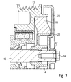
- FIG. 2 Details of the arrangement of inertia mass 20 at compressor shaft 16 can be seen in Figure 2 .
- hub 14 can be seen which is arranged on compressor shaft 16.
- Compressor shaft 16 extends through and beyond hub 14 so that there is a free end at which inertia mass 20 is arranged.
- Connection 22 is here formed by a spring element which ensures a non-rotatable connection between compressor shaft 16 and inertia mass 20 by engaging into a groove in compressor shaft 16 on the one hand, and a corresponding recess in inertia mass 20 on the other hand.
- Fixation 24 is here formed by a counter screw which prevents that inertia mass 20 is separated from compressor shaft 16 in an axial direction.
- inertia mass 20 With respect to compressor shaft 16 is ensured by shoulder 26 on inertia mass 20, which here internally engages at a corresponding surface of hub 14.
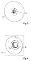
- connection 22 is here formed by splines which are provided along the inner opening of inertia mass 20.
- Compressor shaft 16 has complementary splines which receive inertia mass 20.
- a counter screw can be used as fixation 24 for ensuring that inertia mass 20 is properly kept at its location on compressor shaft 16.
Landscapes
- Engineering & Computer Science (AREA)
- General Engineering & Computer Science (AREA)
- Mechanical Engineering (AREA)
- Manufacturing & Machinery (AREA)
- Physics & Mathematics (AREA)
- Acoustics & Sound (AREA)
- Aviation & Aerospace Engineering (AREA)
- Compressors, Vaccum Pumps And Other Relevant Systems (AREA)
Abstract
Description
- The invention relates to a refrigerant compressor for an air conditioning system, in particular for a vehicle, having a drive pulley, a compressor shaft to which the drive pulley is operatively connected.
- A refrigerant compressor of this type is known from
DE 102 54 937 A1 . The pulley is connected via a torque limiter to the hub which in turn is connected to the compressor shaft. - The object of the invention is to reduce noise which results from excitation from a motor driving the compressor and from rotational belt imbalances. The object of the invention is further to shift the resonance frequency of the compressor to a frequency range which is different from the range of excitation frequencies to which the compressor is subjected and which result from the drive rotating the pulley.
- In order to solve this object, the invention provides a refrigerant compressor of the type mentioned above, which is characterized in that an inertia mass is provided which is directly connected to the compressor shaft. The invention is based on the recognition that a favorable effect can be provided by using an inertia wheel which is directly connected to the compressor shaft. This allows to directly increase the inertia of the compressor shaft without incurring any additional load on the hub. Furthermore, any tolerances and potential imbalance introduced by the hub is avoided. Furthermore, the inertia of the inertia mass does not result in an additional load acting on the connection between the compressor shaft and the hub.
- According to a preferred embodiment, the inertia mass is an inertia wheel. An inertia wheel allows introducing a high additional inertia while requiring only a small space. The additional inertia provided by the inertia wheel can be of 200 to 800 kg*mm2.
- According to an embodiment of the invention, a press fit connection is provided between the compressor shaft and the inertia mass. This type of connection is advantageous as it provides a good centering effect of the inertia mass with respect to the compressor shaft.
- According to an alternative embodiment, an adhesive connection can be provided between the compressor shaft and the inertia mass.
- According to a still further embodiment, a mechanical connection is provided between the compressor shaft and the inertia mass. Using a mechanical connection is advantageous as it allows an easy disassembling of the inertia mass from the compressor shaft.
- The mechanical connection can be formed by a thread on the compressor shaft, onto which the inertia mass is threaded. This results in a very simple mounting process.
- It is however more preferred to have the mechanical connection which provides for a positive fit regarding a rotation of the inertia mass relative to the compressor shaft. Examples for such positive fit are a pin which prevents a relative rotation of the inertia mass with respect to the compressor shaft, or a spring. This type of mechanical connection ensures that there will be no rotation of the inertia mass relative to the compressor shaft despite any vibrations which might occur.
- Another advantageous embodiment consists in the mechanical connection being a spline connection between the inertia mass and the compressor shaft, which is advantageous as it allows to reliably transmit high torques.
- For all embodiments using a positive, non-rotatable connection between the inertia mass and the compressor shaft, there is the significant advantage that there is no risk of the inertia disk becoming detached from the compressor shaft as the result of torsional vibrations which during operation of the compressor act on the connection between the inertia disk and the compressor shaft. The same is true in case of a high torque which can act between the compressor shaft and the inertia disk in case of abrupt changes of the rotational speed of the compressor shaft.
- Preferably, a fixation is provided for securing the inertia mass. The fixation provides additional security against unintentional rotation of the inertia mass with respect to the compressor shaft or against unintentional disintegration. The fixation can for example be formed by a counter screw. It is also possible to form the fixation by an adhesive. Still further, the fixation can be formed by a mechanical formation such as a spring element, a pin, a tooth profile or a counter screw.
- According to a preferred embodiment of the invention, the inertia mass is mechanically centered to the hub. This reduces the risk of an imbalance of the inertia mass, in particular if the connection between the inertia mass and the compressor shaft does in itself not provide for a centering effect.
- Preferably, the inertia mass has a shoulder which engages at an associated surface of the hub. This structure can be used for automatically centering the inertia mass with respect to the hub and hence the compressor shaft when the inertia mass is being mounted to the compressor shaft.
- Preferably, the inertia mass has a rotational inertia of 200 to 800 kg*mm2. This range has proven to be a good compromise between a good effect of the inertia mass on the one hand and a reasonable weight of it at the other hand.
- The invention will now be described with reference to different embodiments, which are shown in the enclosed drawings. In the drawings,
-
Figure 1 schematically shows a refrigerant compressor according to the invention; -
Figure 2 shows a cross section through the end of the compressor shaft where the drive pulley and the inertia mass are being arranged; -
Figure 3 shows a perspective view of an inertia mass according to an alternative construction; and -
Figure 4 shows the central part of the inertia mass ofFigure 3 at an enlarged scale. -
Figure 1 shows arefrigerant compressor 10 which can be in particular used in a vehicle as part of an air conditioning system. By operating the refrigerant compressor, a refrigerant provided at the suction side of the compressor is compressed and discharged at a higher pressure at the output side. -
Refrigerant compressor 10 is externally driven. For driving the compressor, adrive pulley 12 is provided at which a belt drive (not shown) engages. The belt drive can be connected to a motor of the vehicle or to a different mechanism dedicated explicitly for driving the refrigerant compressor. - The rotary motion of
drive pulley 12 is transmitted to ahub 14 which is non-rotatably connected to acompressor shaft 16. - In practice, additional means such as vibration dampers or a torque limiter are provided between
drive pulley 12 andhub 14. As they are not relevant here, they are only schematically indicated withreference numeral 18. -
Compressor shaft 16 drives the mechanism ofrefrigerant compressor 10 which compresses the refrigerant. As an example,compressor shaft 16 can drive a swash plate which is connected to pistons such that a rotary motion of the swash plate is transformed into a reciprocating motion of the pistons. - In order to ensure a smoother rotation of
compressor shaft 16, aninertia mass 20 is connected non-rotatably tocompressor shaft 16. Inertiamass 20 is here formed as an inertia disk. It can be formed as a single, integral piece or could be formed as a composite part consisting of two or more elements. - Preferably,
inertia mass 20 is made from steel and has a rotational inertia of 200 to 800 kg*mm2. - As can be seen in
Figure 1 ,inertia mass 20 is directly connected tocompressor shaft 16. To this end,compressor shaft 16 extends throughhub 14 and beyond the hub so that there is a free forward end of the compressor shaft to whichinertia mass 20 can be directly connected. Havinginertia mass 20 act directly oncompressor shaft 16 ensures that there are no intermediate elements which are stressed by the damping effect whichinertia mass 20 exerts oncompressor shaft 16. - Inertia
mass 20 is connected tocompressor shaft 16 by a connection which prevents a relative rotation between the two elements. This connection is schematically depicted inFigure 1 withreference numeral 22. - One example for such connection between the compressor shaft and the inertia mass is a press fit which ensures that there is sufficient frictional contact between a central bore of
inertia mass 20 and the outer surface ofcompressor shaft 16. The press fit can be obtained by a slight taper oncompressor shaft 16, onto whichinertia mass 20 is pressed in an axial direction, or byheating inertia mass 20 and arranging it in a heated condition oncompressor shaft 16. The advantage of a press fit is that there is no risk of detachment if the torque acting between the inertia disk and the compressor shaft exceeds the level of torque which can be transmitted between disk and shaft. Should such condition occur, there simply is some slippage and rotation of the inertia disk relative to the compressor shaft until the acting torque drops below the design torque. - Another example for
connection 22 betweencompressor shaft 16 andinertia mass 20 is an adhesive connection. For such connection,inertia mass 20 is preferably provided with a cylindrical central surface which extends over a certain axial length so as to provide a sufficiently large surface area for forming the adhesive connection. - Another example for
connection 22 is a mechanical connection between the compressor shaft and the inertia mass.Mechanical connection 22 can be a thread oncompressor shaft 16, onto whichinertia mass 20 is threaded. - More preferably, the mechanical connection is a splined connection which uses cooperating splines in a central opening of
inertia mass 20 and on outer surface ofcompressor shaft 16.Mechanical connection 22 can also be formed by a pin, a keying element or a spring which prevents relative rotation betweencompressor shaft 16 andinertia mass 20. - Using a mechanical connection which prevents, by interengaging structures which provide a positive mechanical connection between the shaft and the disk, any rotation of the inertia disk relative to the compressor shaft has some advantages. During operation of the compressor, torsional vibrations almost permanently act on the connection between the inertia disk and the compressor shaft. These torsional vibrations are the consequence from fluctuations in the torque produced by the combustion engine driving the compressor and from a certain elasticity in the drive from the combustion engine to the compressor. On top of torque fluctuations, any change of the speed of the compressor also results in a torque load on the connection from the compressor shaft to the inertia disk. Using a mechanical connection such as splines, keys, pins etc. allows to reliably transmit the torque between the disk and the shaft over a long lifetime.
- In addition to
connection 22, afixation 24 is provided which acts as a security means. In other words, the purpose offixation 24 is to ensure thatconnection 22 remains intact. -
Fixation 24 can be formed by a counter screw which provides an additional fixation effect.Fixation 24 can also be formed by an adhesive which is for example applied to a threaded connection betweencompressor shaft 16 andinertia mass 20.Fixation 24 can also be formed by a mechanical element such as a spring, a pin or a tooth profile, for example at a stop shoulder oncompressor shaft 16 against whichinertia mass 20 is threaded. - In order to improve the centering of
inertia mass 20 with respect tocompressor shaft 16, a mechanical centering ofinertia mass 20 is provided which is independent from any centering or positioning effect achieved byconnection 22. InFigure 1 , it can be seen thatinertia mass 20 is provided with ashoulder 26 at itsside facing hub 14, which engages at an associated circular surface ofhub 14.Shoulder 26 and the corresponding surface ofhub 14 are formed with such tolerances thatinertia mass 20 is precisely centered by cooperation of these surfaces, resulting ininertia mass 20 being precisely centered with respect tocompressor shaft 16. - Details of the arrangement of
inertia mass 20 atcompressor shaft 16 can be seen inFigure 2 . InFigure 2 ,hub 14 can be seen which is arranged oncompressor shaft 16.Compressor shaft 16 extends through and beyondhub 14 so that there is a free end at whichinertia mass 20 is arranged.Connection 22 is here formed by a spring element which ensures a non-rotatable connection betweencompressor shaft 16 andinertia mass 20 by engaging into a groove incompressor shaft 16 on the one hand, and a corresponding recess ininertia mass 20 on the other hand.Fixation 24 is here formed by a counter screw which prevents thatinertia mass 20 is separated fromcompressor shaft 16 in an axial direction. - The proper position of
inertia mass 20 with respect tocompressor shaft 16 is ensured byshoulder 26 oninertia mass 20, which here internally engages at a corresponding surface ofhub 14. - In
Figures 3 and 4 , an alternative construction ofinertia mass 20 is shown, with the difference to the embodiment ofFigure 2 being thatconnection 22 is here formed by splines which are provided along the inner opening ofinertia mass 20.Compressor shaft 16 has complementary splines which receiveinertia mass 20. A counter screw can be used asfixation 24 for ensuring thatinertia mass 20 is properly kept at its location oncompressor shaft 16.
Claims (16)
- A refrigerant compressor (10) for an air conditioning system, in particular for a vehicle, having a drive pulley (12), a compressor shaft (16) to which the drive pulley (12) is operatively connected, characterized in that it comprises an inertia mass (20) directly connected to the compressor shaft (16).
- The compressor as defined in claim 1 wherein the inertia mass (20) is an inertia disk.
- The compressor as defined in claim 1 or claim 2 wherein a press fit connection (22) is provided between the compressor shaft (16) and the inertia mass (20).
- The compressor as defined in claim 1 or claim 2 wherein an adhesive connection (22) is provided between the compressor shaft (16) and the inertia mass (20).
- The compressor as defined in claim 1 or claim 2 wherein a mechanical connection (22) is provided between the compressor shaft (16) and the inertia mass (20).
- The compressor as defined in claim 5 wherein the mechanical connection (22) is a thread on the compressor shaft (16), onto which the inertia mass (20) is threaded.
- The compressor as defined in claim 5 wherein the mechanical connection (22) is a splined connection.
- The compressor as defined in claim 5 wherein the mechanical connection (22) is formed by a pin, a keying element or a spring.
- The compressor as defined in any of the preceding claims wherein a fixation (24) is provided for securing the inertia mass (20)to the compressor shaft (16).
- The compressor as defined in claim 9 wherein the fixation (24) is formed by a counter screw.
- The compressor as defined in claim 9 wherein the fixation (24) is formed by an adhesive.
- The compressor as defined in claim 9 wherein the fixation (24) is a mechanical formation such as a spring element, a pin, a tooth profile or a counter screw.
- The compressor as defined in any of the preceding claims wherein the compressor shaft (16) extends through a hub (14) to which the drive pulley (12) is connected, the inertia mass (20) being arranged at the free end of the compressor shaft (16).
- The compressor as defined in claim 13 wherein the inertia mass (20) is mechanically centered to the hub (14).
- The compressor as defined in claim 14 wherein the inertia mass (20) has a shoulder (26) which engages at an associated surface of the hub (14).
- The compressor as defined in an of the preceding claims wherein the inertia mass (20) has a rotational inertia of 200 to 800 kg*mm2.
Priority Applications (1)
| Application Number | Priority Date | Filing Date | Title |
|---|---|---|---|
| EP14307097.7A EP3034874A1 (en) | 2014-12-19 | 2014-12-19 | Refrigerant compressor |
Applications Claiming Priority (1)
| Application Number | Priority Date | Filing Date | Title |
|---|---|---|---|
| EP14307097.7A EP3034874A1 (en) | 2014-12-19 | 2014-12-19 | Refrigerant compressor |
Publications (1)
| Publication Number | Publication Date |
|---|---|
| EP3034874A1 true EP3034874A1 (en) | 2016-06-22 |
Family
ID=52347133
Family Applications (1)
| Application Number | Title | Priority Date | Filing Date |
|---|---|---|---|
| EP14307097.7A Withdrawn EP3034874A1 (en) | 2014-12-19 | 2014-12-19 | Refrigerant compressor |
Country Status (1)
| Country | Link |
|---|---|
| EP (1) | EP3034874A1 (en) |
Cited By (1)
| Publication number | Priority date | Publication date | Assignee | Title |
|---|---|---|---|---|
| WO2019115721A1 (en) * | 2017-12-15 | 2019-06-20 | Knorr-Bremse Systeme für Nutzfahrzeuge GmbH | Drive arrangement for a compressor of a utility vehicle |
Citations (3)
| Publication number | Priority date | Publication date | Assignee | Title |
|---|---|---|---|---|
| US20030012661A1 (en) * | 2001-06-28 | 2003-01-16 | Takeshi Kawata | Power transmission mechanism and compressor |
| US20030098007A1 (en) * | 2001-11-26 | 2003-05-29 | Yasuo Tabuchi | Torque transmission device having torque limiter |
| JP2009293645A (en) * | 2008-06-02 | 2009-12-17 | Denso Corp | Torque transmission device |
-
2014
- 2014-12-19 EP EP14307097.7A patent/EP3034874A1/en not_active Withdrawn
Patent Citations (4)
| Publication number | Priority date | Publication date | Assignee | Title |
|---|---|---|---|---|
| US20030012661A1 (en) * | 2001-06-28 | 2003-01-16 | Takeshi Kawata | Power transmission mechanism and compressor |
| US20030098007A1 (en) * | 2001-11-26 | 2003-05-29 | Yasuo Tabuchi | Torque transmission device having torque limiter |
| DE10254937A1 (en) | 2001-11-26 | 2003-06-05 | Denso Corp | Torque transmission device in the torque limiter |
| JP2009293645A (en) * | 2008-06-02 | 2009-12-17 | Denso Corp | Torque transmission device |
Cited By (1)
| Publication number | Priority date | Publication date | Assignee | Title |
|---|---|---|---|---|
| WO2019115721A1 (en) * | 2017-12-15 | 2019-06-20 | Knorr-Bremse Systeme für Nutzfahrzeuge GmbH | Drive arrangement for a compressor of a utility vehicle |
Similar Documents
| Publication | Publication Date | Title |
|---|---|---|
| US6332842B1 (en) | Rotation transmitter having torque limiting mechanism | |
| JP6040844B2 (en) | Power transmission device | |
| US9631681B2 (en) | Gear mechanism for motor vehicles | |
| CN111065836A (en) | Torque limiter for a drive train | |
| US20180045253A1 (en) | Fan, motor driving assembly and load connecting mechanism thereof | |
| KR101927539B1 (en) | A pully-hub assembly for compressor | |
| KR20050075731A (en) | Apparatus for transmitting a torque from motor to compressor | |
| EP1146241A2 (en) | Torque limiting mechanism | |
| EP3676514B1 (en) | Screw compressor | |
| KR101175268B1 (en) | Power transmission apparatus for a compressor | |
| EP3034875B1 (en) | Refrigerant compressor | |
| JP4134470B2 (en) | Power transmission device | |
| JP2001041308A (en) | Power transmission device | |
| US8678156B2 (en) | Shiftable friction clutch for actuation with a flowable pressure medium | |
| EP1725789B1 (en) | A pulley assembly | |
| JP2003254402A (en) | Power transmission device having torque limiter | |
| KR200400967Y1 (en) | Structure of power transfer for clutchless compressor | |
| CN211901373U (en) | Clutch driving disc of automobile air conditioner compressor | |
| JP4013628B2 (en) | Power transmission device | |
| KR101841280B1 (en) | Power transmission apparatus for a compressor | |
| EP2175162B1 (en) | Power transmission device | |
| CN102359509A (en) | Compressor clutch device with variable displacement and swash plate | |
| KR20080106141A (en) | Power Train of Clutchless Compressor | |
| KR101614694B1 (en) | A torque ring having a preventing structure of fatigue failure in a coilless cluch for a compressor | |
| KR102067138B1 (en) | Power transmission device of comppressor |
Legal Events
| Date | Code | Title | Description |
|---|---|---|---|
| PUAI | Public reference made under article 153(3) epc to a published international application that has entered the european phase |
Free format text: ORIGINAL CODE: 0009012 |
|
| AK | Designated contracting states |
Kind code of ref document: A1 Designated state(s): AL AT BE BG CH CY CZ DE DK EE ES FI FR GB GR HR HU IE IS IT LI LT LU LV MC MK MT NL NO PL PT RO RS SE SI SK SM TR |
|
| AX | Request for extension of the european patent |
Extension state: BA ME |
|
| STAA | Information on the status of an ep patent application or granted ep patent |
Free format text: STATUS: REQUEST FOR EXAMINATION WAS MADE |
|
| 17P | Request for examination filed |
Effective date: 20161219 |
|
| RBV | Designated contracting states (corrected) |
Designated state(s): AL AT BE BG CH CY CZ DE DK EE ES FI FR GB GR HR HU IE IS IT LI LT LU LV MC MK MT NL NO PL PT RO RS SE SI SK SM TR |
|
| STAA | Information on the status of an ep patent application or granted ep patent |
Free format text: STATUS: EXAMINATION IS IN PROGRESS |
|
| 17Q | First examination report despatched |
Effective date: 20180105 |
|
| STAA | Information on the status of an ep patent application or granted ep patent |
Free format text: STATUS: THE APPLICATION HAS BEEN WITHDRAWN |
|
| 18W | Application withdrawn |
Effective date: 20200908 |