EP3034841A1 - Gas turbine engine optimization control device - Google Patents
Gas turbine engine optimization control device Download PDFInfo
- Publication number
- EP3034841A1 EP3034841A1 EP14836204.9A EP14836204A EP3034841A1 EP 3034841 A1 EP3034841 A1 EP 3034841A1 EP 14836204 A EP14836204 A EP 14836204A EP 3034841 A1 EP3034841 A1 EP 3034841A1
- Authority
- EP
- European Patent Office
- Prior art keywords
- value
- control parameter
- fuel consumption
- specific fuel
- pressure turbine
- Prior art date
- Legal status (The legal status is an assumption and is not a legal conclusion. Google has not performed a legal analysis and makes no representation as to the accuracy of the status listed.)
- Granted
Links
- 238000005457 optimization Methods 0.000 title claims abstract description 70
- 239000000446 fuel Substances 0.000 claims abstract description 82
- 238000013459 approach Methods 0.000 claims abstract description 3
- 238000001816 cooling Methods 0.000 claims description 6
- 238000000605 extraction Methods 0.000 claims description 6
- 238000011156 evaluation Methods 0.000 description 28
- 238000013528 artificial neural network Methods 0.000 description 6
- 238000010586 diagram Methods 0.000 description 6
- 238000000034 method Methods 0.000 description 6
- 238000012937 correction Methods 0.000 description 4
- 230000000875 corresponding effect Effects 0.000 description 4
- 238000012545 processing Methods 0.000 description 3
- 238000004364 calculation method Methods 0.000 description 2
- 238000001514 detection method Methods 0.000 description 2
- 230000006866 deterioration Effects 0.000 description 2
- 230000001276 controlling effect Effects 0.000 description 1
- 230000002596 correlated effect Effects 0.000 description 1
- 230000007423 decrease Effects 0.000 description 1
- 239000012636 effector Substances 0.000 description 1
- 230000000694 effects Effects 0.000 description 1
- 238000002945 steepest descent method Methods 0.000 description 1
- 230000007704 transition Effects 0.000 description 1
Images


Classifications
-
- F—MECHANICAL ENGINEERING; LIGHTING; HEATING; WEAPONS; BLASTING
- F02—COMBUSTION ENGINES; HOT-GAS OR COMBUSTION-PRODUCT ENGINE PLANTS
- F02C—GAS-TURBINE PLANTS; AIR INTAKES FOR JET-PROPULSION PLANTS; CONTROLLING FUEL SUPPLY IN AIR-BREATHING JET-PROPULSION PLANTS
- F02C9/00—Controlling gas-turbine plants; Controlling fuel supply in air- breathing jet-propulsion plants
- F02C9/48—Control of fuel supply conjointly with another control of the plant
- F02C9/50—Control of fuel supply conjointly with another control of the plant with control of working fluid flow
- F02C9/54—Control of fuel supply conjointly with another control of the plant with control of working fluid flow by throttling the working fluid, by adjusting vanes
-
- F—MECHANICAL ENGINEERING; LIGHTING; HEATING; WEAPONS; BLASTING
- F02—COMBUSTION ENGINES; HOT-GAS OR COMBUSTION-PRODUCT ENGINE PLANTS
- F02C—GAS-TURBINE PLANTS; AIR INTAKES FOR JET-PROPULSION PLANTS; CONTROLLING FUEL SUPPLY IN AIR-BREATHING JET-PROPULSION PLANTS
- F02C9/00—Controlling gas-turbine plants; Controlling fuel supply in air- breathing jet-propulsion plants
- F02C9/16—Control of working fluid flow
- F02C9/20—Control of working fluid flow by throttling; by adjusting vanes
- F02C9/22—Control of working fluid flow by throttling; by adjusting vanes by adjusting turbine vanes
-
- F—MECHANICAL ENGINEERING; LIGHTING; HEATING; WEAPONS; BLASTING
- F02—COMBUSTION ENGINES; HOT-GAS OR COMBUSTION-PRODUCT ENGINE PLANTS
- F02C—GAS-TURBINE PLANTS; AIR INTAKES FOR JET-PROPULSION PLANTS; CONTROLLING FUEL SUPPLY IN AIR-BREATHING JET-PROPULSION PLANTS
- F02C9/00—Controlling gas-turbine plants; Controlling fuel supply in air- breathing jet-propulsion plants
- F02C9/26—Control of fuel supply
- F02C9/44—Control of fuel supply responsive to the speed of aircraft, e.g. Mach number control, optimisation of fuel consumption
-
- G—PHYSICS
- G05—CONTROLLING; REGULATING
- G05B—CONTROL OR REGULATING SYSTEMS IN GENERAL; FUNCTIONAL ELEMENTS OF SUCH SYSTEMS; MONITORING OR TESTING ARRANGEMENTS FOR SUCH SYSTEMS OR ELEMENTS
- G05B13/00—Adaptive control systems, i.e. systems automatically adjusting themselves to have a performance which is optimum according to some preassigned criterion
- G05B13/02—Adaptive control systems, i.e. systems automatically adjusting themselves to have a performance which is optimum according to some preassigned criterion electric
- G05B13/0205—Adaptive control systems, i.e. systems automatically adjusting themselves to have a performance which is optimum according to some preassigned criterion electric not using a model or a simulator of the controlled system
- G05B13/021—Adaptive control systems, i.e. systems automatically adjusting themselves to have a performance which is optimum according to some preassigned criterion electric not using a model or a simulator of the controlled system in which a variable is automatically adjusted to optimise the performance
-
- G—PHYSICS
- G05—CONTROLLING; REGULATING
- G05B—CONTROL OR REGULATING SYSTEMS IN GENERAL; FUNCTIONAL ELEMENTS OF SUCH SYSTEMS; MONITORING OR TESTING ARRANGEMENTS FOR SUCH SYSTEMS OR ELEMENTS
- G05B13/00—Adaptive control systems, i.e. systems automatically adjusting themselves to have a performance which is optimum according to some preassigned criterion
- G05B13/02—Adaptive control systems, i.e. systems automatically adjusting themselves to have a performance which is optimum according to some preassigned criterion electric
- G05B13/0205—Adaptive control systems, i.e. systems automatically adjusting themselves to have a performance which is optimum according to some preassigned criterion electric not using a model or a simulator of the controlled system
- G05B13/024—Adaptive control systems, i.e. systems automatically adjusting themselves to have a performance which is optimum according to some preassigned criterion electric not using a model or a simulator of the controlled system in which a parameter or coefficient is automatically adjusted to optimise the performance
-
- F—MECHANICAL ENGINEERING; LIGHTING; HEATING; WEAPONS; BLASTING
- F05—INDEXING SCHEMES RELATING TO ENGINES OR PUMPS IN VARIOUS SUBCLASSES OF CLASSES F01-F04
- F05D—INDEXING SCHEME FOR ASPECTS RELATING TO NON-POSITIVE-DISPLACEMENT MACHINES OR ENGINES, GAS-TURBINES OR JET-PROPULSION PLANTS
- F05D2270/00—Control
- F05D2270/01—Purpose of the control system
- F05D2270/20—Purpose of the control system to optimize the performance of a machine
-
- F—MECHANICAL ENGINEERING; LIGHTING; HEATING; WEAPONS; BLASTING
- F05—INDEXING SCHEMES RELATING TO ENGINES OR PUMPS IN VARIOUS SUBCLASSES OF CLASSES F01-F04
- F05D—INDEXING SCHEME FOR ASPECTS RELATING TO NON-POSITIVE-DISPLACEMENT MACHINES OR ENGINES, GAS-TURBINES OR JET-PROPULSION PLANTS
- F05D2270/00—Control
- F05D2270/70—Type of control algorithm
- F05D2270/709—Type of control algorithm with neural networks
Definitions
- the present invention relates to a gas turbine engine optimization control device.
- a gas turbine engine control device that controls an engine by the number of revolutions or a pressure ratio correlated with thrust of a gas turbine engine
- a system an SISO (Single Input Single Output) system
- a specific fuel consumption (SFC) cannot be controlled to be constant, and it continuously changes.
- variable cycle engine is the engine that adjusts a cycle so that the specific fuel consumption SFC is made to be a minimum by various effectors, such as a variable mechanism, in addition to adjustment of the fuel flow rate.
- Schedule control utilizing a detection signal, such as a sensor signal, is generally used for controlling the variable mechanism.
- each module such as a fan, a compressor, a combustor, a high-pressure turbine, and a low-pressure turbine, deteriorates.
- the schedule control of the gas turbine engine is performed, there has been a problem that the specific fuel consumption SFC is not always a minimum in any engine depending on a degree of deterioration of such an each module, or variation for each number machine.
- the present invention has been made in view of such a problem of a conventional technology, and an object thereof is to provide a gas turbine engine optimization control device that automatically searches for a variable mechanism command to always make a specific fuel consumption SFC to be a minimum by an optimization control technique in a variable cycle engine, always optimizes the specific fuel consumption to be the minimum even though the engine is deteriorated or performance has variation for each number machine, and that can achieve reduction of operational cost.
- An aspect of the present invention is a gas turbine engine optimization control device, the device including: a specific fuel consumption estimation operation section that estimates a specific fuel consumption using a sensor feedback value of a control parameter of a variable mechanism given for each predetermined operation period; a control parameter reoperation section that determines a change between a specific fuel consumption estimation value based on a sensor feedback value of the control parameter of the variable mechanism in a previous operation period and a specific fuel consumption estimation value based on a sensor feedback value of the control parameter of the variable mechanism in this operation period, and determines a new control parameter command value of the variable mechanism with which the specific fuel consumption estimation value approaches a minimum; and a control parameter command value operation section that adds the new control parameter command value of the variable mechanism determined by the control parameter reoperation section to a preset control parameter initial value of the variable mechanism, and outputs the value as a control parameter command value of the variable mechanism in a next operation period.
- a low-pressure turbine variable stator vane angle may be used as the control parameter of the variable mechanism.
- any of an exhaust nozzle area, a compressor variable stator vane angle, a high-pressure turbine case cooling air flow rate, a low-pressure turbine case cooling air flow rate, a high-pressure turbine variable stator vane angle, a fan bypass area, an extraction force, and extraction steam may be used as the control parameter of the variable mechanism.
- control parameter command value of the variable mechanism for always making the specific fuel consumption to be a minimum is automatically searched for by the optimization control technique of the gas turbine engine, and the gas turbine engine can be operated while always optimizing the specific fuel consumption even though the engine is deteriorated or performance has variation for each number machine, thus enabling to achieve reduction of operational cost of the gas turbine engine.
- a gas turbine engine optimization control device of the embodiment shown in Fig. 1 includes a computer system.
- a low-pressure turbine variable stator vane angle LPTVSV is controlled as a variable mechanism for optimization control of a variable cycle engine.
- control to adjust not only the low-pressure turbine variable stator vane angle LPTVSV but a fan bypass outlet area and an exhaust nozzle area can also be employed.
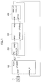
- the gas turbine engine optimization control device shown in Fig. 1 includes an optimization controller 100 and an engine control section 200 as main operation elements, an actuator drive section 300, and an actual engine 400.
- the optimization controller 100 manages a specific fuel consumption estimation operation section (a specific fuel consumption estimation operation unit), a control parameter command value operation section (a control parameter command value operation unit), and a control parameter reoperation section (a control parameter reoperation unit).
- the actuator drive section 300 gives a physical drive force to a corresponding actuator of the actual engine 400 with respect to command value outputs from the optimization controller 100 and the engine control section 200.
- the actual engine 400 is controlled to consume fuel while optimizing a specific fuel consumption SFC, and to generate a thrust.
- Sensor values are then fed back to the optimization controller 100 and the engine control section 200 from a sensor group installed in each place of the actual engine 400.
- the sensor feedback values are represented as a sensor_fb1 and a sensor_fb2.
- the engine thrust command value FNREF is input to the optimization controller 100 from the FNREF input device 1.
- a sensor value sensor_out1 including a low-pressure turbine variable stator vane angle detection value output from the sensor group of the actual engine 400 is input as feedback to the optimization controller 100 as the sensor feedback value sensor_fb1.
- the optimization controller 100 calculates a pilot throttle lever angle command value PLAcmd by an operation to improve the specific fuel consumption SFC that will be described later.
- the pilot throttle lever angle command value PLAcmd is output to the engine control section 200 as a pilot throttle lever angle PLA.
- the optimization controller 100 calculates a low-pressure turbine variable stator vane angle command value LPTVSVREF, and outputs it to the actuator drive section 300.
- the engine control section 200 inputs the pilot throttle lever angle PLA from the optimization controller 100, and also inputs a sensor value sensor_out2 from the actual engine 400 as the sensor feedback value sensor_fb2. The engine control section 200 then calculates a fuel flow rate command value WFREF using the above-described values, and outputs it to the actuator drive section 300.
- the actuator drive section 300 inputs the low-pressure turbine variable stator vane angle command value LPTVSVREF from the optimization controller 100, and also inputs the fuel flow rate command value WFREF from the engine control section 200.
- the actuator drive section 300 then gives a low-pressure turbine variable stator vane angle sensor value LPTVSVact, which is a low-pressure turbine variable stator vane drive signal corresponding to these values, to the actual engine 400, and drives an actual low-pressure turbine variable stator vane LPTVSV by a command angle.
- the actuator drive section 300 gives an actual fuel flow rate signal WFact to the actual engine 400, and supplies fuel to the actual engine 400 with a fuel flow rate corresponding to the actual fuel flow rate signal WFact.
- the actual engine 400 is controlled to be operated by an optimum specific fuel consumption SFC.
- the sensor value sensor_out1 is fed back to the optimization controller 100 and the engine control section 200 as the sensor feedback value sensor_fb1 from the sensor group of the actual engine 400, respectively.
- the sensor value sensor_out2 is fed back to the optimization controller 100 and the engine control section 200 as the sensor feedback value sensor_fb2 from the sensor group, respectively.
- the optimization controller 100 includes a low-pressure turbine variable stator vane angle command value operation section 100-1 and a pilot throttle lever angle command value operation section 100-2. Additionally, the low-pressure turbine variable stator vane angle command value operation section 100-1 inputs the sensor feedback value sensor_fb1, and thereby outputs the low-pressure turbine variable stator vane angle command value LPTVSVREF from an output end DLTLPTVSV by optimum operation control. In addition, the pilot throttle lever angle command value operation section 100-2 of the optimization controller 100 calculates a pilot throttle lever angle corresponding to the input engine thrust command value FNREF, and outputs it as the pilot throttle lever angle command value PLAcmd.
- the above-described low-pressure turbine variable stator vane angle command value operation section 100-1 in the optimization controller 100 includes a neural network operation device 101 and an optimization control operation device 102.
- the low-pressure turbine variable stator vane angle command value operation section 100-1 further includes: previous value holders 103 and 104; a selector 105; step signal devices 108 and 109; and a switch 110.
- the sensor feedback value sensor_fb1 from the actual engine 400 is input to the optimization controller 100.
- the sensor feedback value sensor_fb1 is input to the previous value holder 103, and is input also to the previous value holder 104 through the selector 105.
- the previous value holder 103 holds the newest sensor feedback value sensor_fb1 as an update value, and outputs the sensor feedback value sensor_fb1 held until then until a next update value is input.
- the previous sensor feedback value sensor_fb1 is input to the neural network operation device 101 as a sensor value 'sensor', and is simultaneously input also to the optimization control operation device 102 as the sensor feedback value sensor_fb1.
- the selector 105 selects a low-pressure turbine variable stator vane angle feedback value e_lptvsv_fb from the input sensor feedback values sensor_fb1, and outputs it to the previous value holder 104 as an update value of the low-pressure turbine variable stator vane angle LPTVSV, and the previous value holder 104 holds the value.
- the previous value holder 104 holds a previous value until the update value of the low-pressure turbine variable stator vane angle LPTVSV is input, and outputs the previous value to the switch 110 as the low-pressure turbine variable stator vane angle LPTVSV.
- the neural network operation device 101 estimates a specific fuel consumption SFC of the actual engine 400 using the input sensor value 'sensor', and outputs a specific fuel consumption estimation value SFC_est.
- the specific fuel consumption estimation value SFC_est of the neural network operation device 101 is input to the optimization control operation device 102 as a specific fuel consumption feedback value SFC_fb.
- the optimization control operation device 102 inputs the sensor feedback value sensor_fb1 from the actual engine 400, and inputs the specific fuel consumption estimation value SFC_est as the specific fuel consumption feedback value SFC_fb from the neural network operation device 101.
- the optimization control operation device 102 further inputs a step signal from the step signal device 109. Additionally, when the step signal indicating operation execution is input from the step signal device 109, the optimization control operation device 102 determines a low-pressure turbine variable stator vane angle search value LPTVSV_SEARCHPOINT.
- the optimization control operation device 102 outputs the determined low-pressure turbine variable stator vane angle search value LPTVSV_SEARCHPOINT to the switch 110 from an output end e_lptvsv_searchpoint.
- the optimization control operation device 102 outputs a low-pressure turbine variable stator vane angle optimum value LPTVSV_BEST from an output end e_lptvsv_best.
- the low-pressure turbine variable stator vane angle optimum value LPTVSV_BEST is monitored through Fig. 4 and throughout the whole, which is described later.
- the switch 110 is located at a lower side for a certain time, i.e., until the system is stabilized, and outputs the low-pressure turbine variable stator vane angle LPTVSV from the previous value holder 104 as a low-pressure turbine variable stator vane angle search value DLTPTVSV.
- the switch 110 is switched to an upper side, and outputs the low-pressure turbine variable stator vane angle search value LPTVSV_SEARCHPOINT as the low-pressure turbine variable stator vane angle search value DLTPTVSV.
- the optimization control operation device 102 includes as main components an optimization parameter feedback section 120, a pattern searcher 121, and a limit checker 122.
- the optimization control operation device 102 includes: a pulse generator 125; a logical product operation device 126; initial value setters 127 and 128; a previous value holder 129; and a logic inverter 130.
- the optimization control operation device 102 starts an operation at rise or fall timing (the rise timing is exemplified here) of a pulse of each predetermined operation period generated by the pulse generator 125, for example, a pulse of each 30 seconds, while an enable signal is given.
- the optimization parameter feedback section 120 makes the sensor feedback value sensor_fb1 pass through the selector, and inputs only the low-pressure turbine variable stator vane angle feedback value e_lptvsv_fb to an input end InitPoint of the pattern searcher 121.
- a one-period prior low-pressure turbine variable stator vane angle feedback value e_lptvsv_fb is input to the input end InitPoint of the pattern searcher 121 from the optimization parameter feedback section 120.
- the low-pressure turbine variable stator vane angle feedback value is selected from the sensor feedback values sensor_fb1.
- an evaluation value 'cost' output from the limit checker 122 is input to an input end Cost through the previous value holder 129 and the initial value setter 127.
- the pattern searcher 121 decides an optimization parameter search value for each constant operation period (for example, 30 seconds).
- the pattern searcher 121 outputs a low-pressure turbine variable stator vane angle search value e_lptvsv_searchpoint from an output end SearchPoint.
- the pattern searcher 121 outputs an optimum value of a past low-pressure turbine variable stator vane angle from an output end BestPoint as a low-pressure turbine variable stator vane angle optimum value e_lptvsv_best
- the low-pressure turbine variable stator vane angle search value e_lptvsv_searchpoint is output from the output end SearchPoint, and is input to an input end of a low-pressure turbine variable stator vane angle operation value lptvsv in the limit checker 122.
- the specific fuel consumption feedback value SFC_fb is input to an input end e_sfc of the limit checker 122.
- the limit checker 122 determines whether or not the low-pressure turbine variable stator vane angle search value e_lptvsv_searchpoint determined by the pattern searcher 121 is larger than an upper-limit value, or is smaller than a lower-limit value.
- the limit checker 122 If the low-pressure turbine variable stator vane angle search value e_lptvsv_searchpoint then does not exceed either of the limit values, the limit checker 122 outputs the specific fuel consumption feedback value SFC_fb (the specific fuel consumption estimation value SFC_est) to the previous value holder 129 from an output end thereof as the evaluation value 'cost' to optimize the specific fuel consumption SFC. However, if the low-pressure turbine variable stator vane angle search value e_lptvsv_searchpoint exceeds either of the above-described limit values, the limit checker 122 outputs a preset worst evaluation value 'worstcost' as the evaluation value 'cost'.
- the previous value holder 129 receives this evaluation value 'cost', and updates a hold value.
- the initial value setter 127 holds the worst evaluation value 'worstcost' previously given as an initial value, and outputs the worst evaluation value 'worstcost' to the input end Cost of the pattern searcher 121 at the beginning of calculation. Additionally, if calculation of the system is stabilized after that, and the evaluation value 'cost' comes to be calculated, the initial value setter 127 outputs a value from the previous value holder 129. Consequently, the pattern searcher 121 performs the above-mentioned operation, and outputs the low-pressure turbine variable stator vane angle search value e_lptvsv_searchpoint from the output end SearchPoint. In addition, the pattern searcher 121 outputs the past low-pressure turbine variable stator vane angle optimum value e_lptvsv_best from the output end BestPoint.
- the pattern searcher 121 in the optimization control operation device 102 will be explained in detail using Fig. 5 .
- the pattern searcher 121 performs an operation for each period (for example, 30 seconds) of the enable signal.
- the pattern searcher 121 includes a pattern search execution section 142 that executes a pattern search, and zero value setters 140, 143, 147, and 150 that set zero needed as an initial value of the operation.
- the pattern searcher 121 further includes: previous value holders 144, 145, and 148; a logical sum operation device 141; an adder 146; a comparator 149; multipliers 151 and 152; and adders 153 and 154.
- a search count upper-limit value LoopMax is given to the comparator 149 as a comparison value, an increment value one is given to the adder 146, and a search addition length gain is given to the multipliers 151 and 152 as a predetermined value from a gain setter 160.
- the adder 146 counts a search count. Specifically, the adder 146 adds one to a previous value held by the previous value holder 148, sets the addition value as this search count, and outputs it to the comparator 149.
- the comparator 149 compares the search count calculated by the adder 146 with the search count upper-limit value LoopMax. If this search count reaches the search count upper-limit value, the comparator 149 outputs a search count upper-limit reach flag LoopFinishFlag to the logical sum operation device 141. If not, it does not output the search count upper-limit reach flag LoopFinishFlag. If the search count upper-limit reach flag is input, or a search addition length lower limit reach signal is input, the logical sum operation device 141 outputs a search end flag endflg. If not, it does not output the search end flag endflg.
- the pattern search execution section 142 inputs a previous specific fuel consumption estimation value as a previous evaluation value 'cost', and compares the previous specific fuel consumption estimation value with this specific fuel consumption estimation value. If the specific fuel consumption estimation value is then improved, the pattern search execution section 142 searches in a same direction (course), and decides and outputs a next low-pressure turbine variable stator vane angle command value.
- the pattern searcher 121 adds a control parameter initial value (an initial control parameter) (for example, it is set to be 2.5deg, and is defined as 50%) as a search initial position to the low-pressure turbine variable stator vane angle command value obtained by the pattern search execution section 142, and outputs it as this search position SearchPoint.
- the pattern searcher 121 adds the control parameter initial value also to a previous optimum search value, and outputs a low-pressure turbine variable stator vane angle optimum value BestPoint.
- the search position SearchPoint is output from the SearchPoint output end in the pattern searcher 121 as the low-pressure turbine variable stator vane angle search value e_lptvsv_searchpoint.
- the optimum value BestPoint is output from the BestPoint output end in the pattern searcher 121 as the low-pressure turbine variable stator vane angle optimum value e_lptvsv_best.
- the pattern searcher 121 When the search count reaches the search count upper-limit value LoopMax or a search addition length lower limit, the pattern searcher 121 outputs the search end flag endflg, and ends the pattern search.
- the limit checker 122 includes: an upper limit setter 161; a lower limit setter 162; comparators 163 and 164; a logical sum operation device 165; a worst evaluation value setter 167; an evaluation value output switching signal device 168; an evaluation value switcher 169; and an output switcher 170.
- the limit checker 122 inputs the low-pressure turbine variable stator vane angle operation value lptvsv, and a specific fuel consumption estimation value e_sfc, and outputs a next specific fuel consumption estimation value SFC_est as the evaluation value 'cost'.
- the evaluation value switcher 169 in the limit checker 122 outputs the worst evaluation value 'worstcost'. Otherwise, the evaluation value switcher 169 outputs the specific fuel consumption operation value e_sfc as the specific fuel consumption estimation value SFC_est.
- the output switcher 170 When the evaluation value output switching signal device 168 outputs a switching signal, the output switcher 170 outputs the specific fuel consumption operation value e_sfc as the evaluation value 'cost'. Meanwhile, when the switching signal is not output, the output switcher 170 outputs the output of the evaluation value switcher 169 as the evaluation value 'cost'. As a result of this, even when the evaluation value 'cost' exceeds a worst value to a worse side, the output switcher 170 is prevented from outputting a bad value due to the evaluation value 'cost' exceeding the limit by outputting the worst evaluation value 'worstcost'.
- the evaluation value 'cost' is output as an evaluation value of a specific fuel consumption from an output end 'cost' in the limit checker 122 in Fig. 4 .
- the specific fuel consumption estimation value SFC_est is determined, and the specific fuel consumption estimation value SFC_est is input to the optimization control operation device 102.
- a search for the low-pressure turbine variable stator vane angle LPTVSV which is a control parameter with which the specific fuel consumption SFC as the evaluation value 'cost' is a minimum, is performed.
- a previous specific fuel consumption estimation value is input to the Cost input end for each 30 seconds as a constant operation period.
- the low-pressure turbine variable stator vane angle feedback value e_lptvsv_fb is fed back to the input end InitPoint from a sensor.
- the pattern searcher 121 observes in search of this specific fuel consumption estimation value from the previous specific fuel consumption estimation value and the low-pressure turbine variable stator vane angle feedback value e_lptvsv_fb (step ST1). If this specific fuel consumption estimation value is then improved more than the previous specific fuel consumption estimation value, processing branches to YES in step ST1. Additionally, the pattern searcher 121 searches for and outputs a low-pressure turbine variable stator vane angle search value in a direction where a next specific fuel consumption estimation value is reduced (steps ST2, ST4, and ST5).
- step ST1 if the low-pressure turbine variable stator vane angle search value is in a direction where this specific fuel consumption estimation value increases more than the previous specific fuel consumption estimation value, processing branches to NO in step ST1.
- the pattern searcher 121 searches in an opposite direction in order to reduce a change width of the low-pressure turbine variable stator vane angle search value, and determines the low-pressure turbine variable stator vane angle search value (steps ST3, ST6, and ST7).
- a pattern search method executed by the pattern searcher 121 described above is a general steepest descent method.
- the low-pressure turbine variable stator vane angle search value is added to a control parameter search initial value InitPoint, the addition value is set to be a next low-pressure turbine variable stator vane angle command value, and operation of the actual engine 400 is performed in conjunction with a fuel flow rate etc. (step ST8).
- a control parameter to be optimized is not limited to the low-pressure turbine variable stator vane angle LPTVSV used in the above-described embodiment. Any of an exhaust nozzle area, a compressor variable stator vane angle, a high-pressure turbine case cooling air flow rate, a low-pressure turbine case cooling air flow rate, a high-pressure turbine variable stator vane angle, a fan bypass area, an extraction force, and extraction steam may be used.
- the limit checker 122 in the optimization control operation device 102 confirms whether or not the low-pressure turbine variable stator vane angle command value exceeds a limit value. If the low-pressure turbine variable stator vane angle command value is smaller than the limit value, the limit checker 122 uses the previous specific fuel consumption estimation value as an evaluation value of the search. If the low-pressure turbine variable stator vane angle command value exceeds the limit value, the limit checker 122 sets the worst evaluation value 'worstcost' to the SFC, and prevents the previous specific fuel consumption estimation value from being updated in subsequent operations.
- Results simulated by the gas turbine engine optimization control device of the above-described embodiment are shown in a graph of Fig. 8.
- Fig. 8 shows transition of a sensor value and an estimation value of the specific fuel consumption SFC started as a control parameter from 50% of a low-pressure turbine variable stator vane angle command value.
- a reference character FN denotes engine thrust.
- a reference character FNest denotes an engine thrust estimation value.
- a reference character WFREF is a fuel flow rate command value.
- a reference character WFact is a fuel flow rate actual value.
- a reference character N1 is an estimation value of an engine speed (a low pressure).
- a reference character N1est is an estimation value of the engine speed (the low pressure).
- a reference character LPTVSVREF is a low-pressure turbine variable stator vane angle command value.
- a reference character LPTVSVact is a low-pressure turbine variable stator vane angle sensor value.
- a reference character SFC is an actual specific fuel consumption.
- a reference character SFC_est is a specific fuel consumption estimation value.
- the low-pressure turbine variable stator vane angle command value LPTVSVREF and the low-pressure turbine variable stator vane angle sensor value LPTVSVact coincide with each other, and both are stable at 0%.
- the specific fuel consumption SFC and the specific fuel consumption estimation value SFC_est are also settled near 97% in association with the movement of the low-pressure turbine variable stator vane angle sensor value LPTVSVact. As a result of this, it can be understood that an optimum value was obtained.
- a correction value of a control parameter command value was added to a previous search value, and the addition value was set to be a next search value using an engine model, in order to search for a control parameter with which the specific fuel consumption SFC could be optimally controlled.
- the correction value of the control parameter command value is added to an initial set value, the addition value is set to be the next search value, and the control parameter with which the specific fuel consumption is made an optimum is searched for.
- the control parameter to quickly reach a minimum specific fuel consumption SFC can be obtained.
Abstract
Description
- The present invention relates to a gas turbine engine optimization control device.
- As a gas turbine engine control device that controls an engine by the number of revolutions or a pressure ratio correlated with thrust of a gas turbine engine, there has been known a system (an SISO (Single Input Single Output) system) that adjusts a fuel flow rate to control the number of revolutions of a fan. In a case of such a gas turbine engine control device, even though the number of revolutions can be controlled to be constant by flight points (an altitude, a jet speed, an air temperature) of a jet, a specific fuel consumption (SFC) cannot be controlled to be constant, and it continuously changes.
- Consequently, a variable cycle engine has been proposed in order to eliminate the continuous change. The variable cycle engine is the engine that adjusts a cycle so that the specific fuel consumption SFC is made to be a minimum by various effectors, such as a variable mechanism, in addition to adjustment of the fuel flow rate. Schedule control utilizing a detection signal, such as a sensor signal, is generally used for controlling the variable mechanism.
- In a gas turbine engine, each module, such as a fan, a compressor, a combustor, a high-pressure turbine, and a low-pressure turbine, deteriorates. However, when the schedule control of the gas turbine engine is performed, there has been a problem that the specific fuel consumption SFC is not always a minimum in any engine depending on a degree of deterioration of such an each module, or variation for each number machine.
-
- Patent Literature 1:
Japanese Patent Laid-Open Publication No. 2000-210152 - Patent Literature 2:
Japanese Patent No. 4540956 - Patent Literature 3:
Japanese Patent Laid-Open Publication No. 2009-197670 - Patent Literature 4:
Japanese Patent Laid-Open Publication No. 2012-215575 - The present invention has been made in view of such a problem of a conventional technology, and an object thereof is to provide a gas turbine engine optimization control device that automatically searches for a variable mechanism command to always make a specific fuel consumption SFC to be a minimum by an optimization control technique in a variable cycle engine, always optimizes the specific fuel consumption to be the minimum even though the engine is deteriorated or performance has variation for each number machine, and that can achieve reduction of operational cost.
- An aspect of the present invention is a gas turbine engine optimization control device, the device including: a specific fuel consumption estimation operation section that estimates a specific fuel consumption using a sensor feedback value of a control parameter of a variable mechanism given for each predetermined operation period; a control parameter reoperation section that determines a change between a specific fuel consumption estimation value based on a sensor feedback value of the control parameter of the variable mechanism in a previous operation period and a specific fuel consumption estimation value based on a sensor feedback value of the control parameter of the variable mechanism in this operation period, and determines a new control parameter command value of the variable mechanism with which the specific fuel consumption estimation value approaches a minimum; and a control parameter command value operation section that adds the new control parameter command value of the variable mechanism determined by the control parameter reoperation section to a preset control parameter initial value of the variable mechanism, and outputs the value as a control parameter command value of the variable mechanism in a next operation period.
- In the above-described gas turbine engine optimization control device, a low-pressure turbine variable stator vane angle may be used as the control parameter of the variable mechanism.
- In addition, in the above-described gas turbine engine optimization control device, any of an exhaust nozzle area, a compressor variable stator vane angle, a high-pressure turbine case cooling air flow rate, a low-pressure turbine case cooling air flow rate, a high-pressure turbine variable stator vane angle, a fan bypass area, an extraction force, and extraction steam may be used as the control parameter of the variable mechanism.
- According to the present invention, the control parameter command value of the variable mechanism for always making the specific fuel consumption to be a minimum is automatically searched for by the optimization control technique of the gas turbine engine, and the gas turbine engine can be operated while always optimizing the specific fuel consumption even though the engine is deteriorated or performance has variation for each number machine, thus enabling to achieve reduction of operational cost of the gas turbine engine.
-
- [
Fig. 1] Fig. 1 is a block diagram showing a system configuration of a gas turbine engine optimization control device of one embodiment of the present invention. - [
Fig. 2] Fig. 2 is a block diagram showing an internal configuration of a controller in the gas turbine engine optimization control device of the above-described embodiment. - [
Fig. 3] Fig. 3 is a block diagram showing an internal configuration of an engine thrust operation section in the controller in the gas turbine engine optimization control device of the above-described embodiment. - [
Fig. 4] Fig. 4 is a block diagram showing an internal configuration of an optimization control operation device in the controller in the gas turbine engine optimization control device of the above-described embodiment. - [
Fig. 5] Fig. 5 is a block diagram showing an internal configuration of a pattern searcher in the above-described optimization control operation device. - [
Fig. 6] Fig. 6 is a block diagram showing an internal configuration of a limit checker in the above-described optimization control operation device. - [
Fig. 7] Fig. 7 is a flow chart of a control parameter value optimum value search of a variable mechanism by the above-described optimization control operation device. - [
Fig. 8] Fig. 8 is a graph showing control characteristics of a practical example of the present invention. - Hereinafter, an embodiment of the present invention will be explained in detail based on drawings. Note that hereinafter, the same or similar components will be explained using the same or similar symbols.
- A gas turbine engine optimization control device of the embodiment shown in
Fig. 1 includes a computer system. In the embodiment, a case will be explained where a low-pressure turbine variable stator vane angle LPTVSV is controlled as a variable mechanism for optimization control of a variable cycle engine. However, as the variable mechanism adjusted for optimization control of a gas turbine engine, control to adjust not only the low-pressure turbine variable stator vane angle LPTVSV but a fan bypass outlet area and an exhaust nozzle area can also be employed. - The gas turbine engine optimization control device shown in
Fig. 1 includes anoptimization controller 100 and anengine control section 200 as main operation elements, anactuator drive section 300, and anactual engine 400. Theoptimization controller 100 manages a specific fuel consumption estimation operation section (a specific fuel consumption estimation operation unit), a control parameter command value operation section (a control parameter command value operation unit), and a control parameter reoperation section (a control parameter reoperation unit). Theactuator drive section 300 gives a physical drive force to a corresponding actuator of theactual engine 400 with respect to command value outputs from theoptimization controller 100 and theengine control section 200. Theactual engine 400 is controlled to consume fuel while optimizing a specific fuel consumption SFC, and to generate a thrust. Sensor values are then fed back to theoptimization controller 100 and theengine control section 200 from a sensor group installed in each place of theactual engine 400. The sensor feedback values are represented as a sensor_fb1 and a sensor_fb2. - It is an engine thrust command value FNREF from an
FNREF input device 1 that is input to the system from an outside. The engine thrust command value FNREF is input to theoptimization controller 100 from the FNREFinput device 1. In addition, a sensor value sensor_out1 including a low-pressure turbine variable stator vane angle detection value output from the sensor group of theactual engine 400 is input as feedback to theoptimization controller 100 as the sensor feedback value sensor_fb1. Additionally, theoptimization controller 100 calculates a pilot throttle lever angle command value PLAcmd by an operation to improve the specific fuel consumption SFC that will be described later. The pilot throttle lever angle command value PLAcmd is output to theengine control section 200 as a pilot throttle lever angle PLA. In addition, theoptimization controller 100 calculates a low-pressure turbine variable stator vane angle command value LPTVSVREF, and outputs it to theactuator drive section 300. - The
engine control section 200 inputs the pilot throttle lever angle PLA from theoptimization controller 100, and also inputs a sensor value sensor_out2 from theactual engine 400 as the sensor feedback value sensor_fb2. Theengine control section 200 then calculates a fuel flow rate command value WFREF using the above-described values, and outputs it to theactuator drive section 300. - The
actuator drive section 300 inputs the low-pressure turbine variable stator vane angle command value LPTVSVREF from theoptimization controller 100, and also inputs the fuel flow rate command value WFREF from theengine control section 200. Theactuator drive section 300 then gives a low-pressure turbine variable stator vane angle sensor value LPTVSVact, which is a low-pressure turbine variable stator vane drive signal corresponding to these values, to theactual engine 400, and drives an actual low-pressure turbine variable stator vane LPTVSV by a command angle. Simultaneously, theactuator drive section 300 gives an actual fuel flow rate signal WFact to theactual engine 400, and supplies fuel to theactual engine 400 with a fuel flow rate corresponding to the actual fuel flow rate signal WFact. As a result of this, theactual engine 400 is controlled to be operated by an optimum specific fuel consumption SFC. Additionally, the sensor value sensor_out1 is fed back to theoptimization controller 100 and theengine control section 200 as the sensor feedback value sensor_fb1 from the sensor group of theactual engine 400, respectively. In addition, the sensor value sensor_out2 is fed back to theoptimization controller 100 and theengine control section 200 as the sensor feedback value sensor_fb2 from the sensor group, respectively. - Next, the
optimization controller 100 will be explained usingFigs. 2 and3 . As shown inFig. 2 , theoptimization controller 100 includes a low-pressure turbine variable stator vane angle command value operation section 100-1 and a pilot throttle lever angle command value operation section 100-2. Additionally, the low-pressure turbine variable stator vane angle command value operation section 100-1 inputs the sensor feedback value sensor_fb1, and thereby outputs the low-pressure turbine variable stator vane angle command value LPTVSVREF from an output end DLTLPTVSV by optimum operation control. In addition, the pilot throttle lever angle command value operation section 100-2 of theoptimization controller 100 calculates a pilot throttle lever angle corresponding to the input engine thrust command value FNREF, and outputs it as the pilot throttle lever angle command value PLAcmd. - As shown in
Fig. 3 , the above-described low-pressure turbine variable stator vane angle command value operation section 100-1 in theoptimization controller 100 includes a neuralnetwork operation device 101 and an optimizationcontrol operation device 102. The low-pressure turbine variable stator vane angle command value operation section 100-1 further includes:previous value holders selector 105;step signal devices switch 110. - The sensor feedback value sensor_fb1 from the
actual engine 400 is input to theoptimization controller 100. The sensor feedback value sensor_fb1 is input to theprevious value holder 103, and is input also to theprevious value holder 104 through theselector 105. - The
previous value holder 103 holds the newest sensor feedback value sensor_fb1 as an update value, and outputs the sensor feedback value sensor_fb1 held until then until a next update value is input. The previous sensor feedback value sensor_fb1 is input to the neuralnetwork operation device 101 as a sensor value 'sensor', and is simultaneously input also to the optimizationcontrol operation device 102 as the sensor feedback value sensor_fb1. - The
selector 105 selects a low-pressure turbine variable stator vane angle feedback value e_lptvsv_fb from the input sensor feedback values sensor_fb1, and outputs it to theprevious value holder 104 as an update value of the low-pressure turbine variable stator vane angle LPTVSV, and theprevious value holder 104 holds the value. Theprevious value holder 104 holds a previous value until the update value of the low-pressure turbine variable stator vane angle LPTVSV is input, and outputs the previous value to theswitch 110 as the low-pressure turbine variable stator vane angle LPTVSV. - The neural
network operation device 101 estimates a specific fuel consumption SFC of theactual engine 400 using the input sensor value 'sensor', and outputs a specific fuel consumption estimation value SFC_est. The specific fuel consumption estimation value SFC_est of the neuralnetwork operation device 101 is input to the optimizationcontrol operation device 102 as a specific fuel consumption feedback value SFC_fb. - The optimization
control operation device 102 inputs the sensor feedback value sensor_fb1 from theactual engine 400, and inputs the specific fuel consumption estimation value SFC_est as the specific fuel consumption feedback value SFC_fb from the neuralnetwork operation device 101. The optimizationcontrol operation device 102 further inputs a step signal from thestep signal device 109. Additionally, when the step signal indicating operation execution is input from thestep signal device 109, the optimizationcontrol operation device 102 determines a low-pressure turbine variable stator vane angle search value LPTVSV_SEARCHPOINT. The optimizationcontrol operation device 102 outputs the determined low-pressure turbine variable stator vane angle search value LPTVSV_SEARCHPOINT to theswitch 110 from an output end e_lptvsv_searchpoint. In addition, simultaneously, the optimizationcontrol operation device 102 outputs a low-pressure turbine variable stator vane angle optimum value LPTVSV_BEST from an output end e_lptvsv_best. The low-pressure turbine variable stator vane angle optimum value LPTVSV_BEST is monitored throughFig. 4 and throughout the whole, which is described later. - The
switch 110 is located at a lower side for a certain time, i.e., until the system is stabilized, and outputs the low-pressure turbine variable stator vane angle LPTVSV from theprevious value holder 104 as a low-pressure turbine variable stator vane angle search value DLTPTVSV. However, when the system is stabilized, and a switching signal is input from thestep signal device 108, theswitch 110 is switched to an upper side, and outputs the low-pressure turbine variable stator vane angle search value LPTVSV_SEARCHPOINT as the low-pressure turbine variable stator vane angle search value DLTPTVSV. - The optimization
control operation device 102 will be explained in more detail usingFig. 4 . The optimizationcontrol operation device 102 includes as main components an optimizationparameter feedback section 120, apattern searcher 121, and alimit checker 122. In addition, the optimizationcontrol operation device 102 includes: apulse generator 125; a logicalproduct operation device 126;initial value setters previous value holder 129; and alogic inverter 130. The optimizationcontrol operation device 102 starts an operation at rise or fall timing (the rise timing is exemplified here) of a pulse of each predetermined operation period generated by thepulse generator 125, for example, a pulse of each 30 seconds, while an enable signal is given. - The optimization
parameter feedback section 120 makes the sensor feedback value sensor_fb1 pass through the selector, and inputs only the low-pressure turbine variable stator vane angle feedback value e_lptvsv_fb to an input end InitPoint of thepattern searcher 121. - A one-period prior low-pressure turbine variable stator vane angle feedback value e_lptvsv_fb is input to the input end InitPoint of the
pattern searcher 121 from the optimizationparameter feedback section 120. The low-pressure turbine variable stator vane angle feedback value is selected from the sensor feedback values sensor_fb1. In addition, an evaluation value 'cost' output from thelimit checker 122 is input to an input end Cost through theprevious value holder 129 and theinitial value setter 127. Additionally, thepattern searcher 121 decides an optimization parameter search value for each constant operation period (for example, 30 seconds). Further, thepattern searcher 121 outputs a low-pressure turbine variable stator vane angle search value e_lptvsv_searchpoint from an output end SearchPoint. In addition, thepattern searcher 121 outputs an optimum value of a past low-pressure turbine variable stator vane angle from an output end BestPoint as a low-pressure turbine variable stator vane angle optimum value e_lptvsv_best. - The low-pressure turbine variable stator vane angle search value e_lptvsv_searchpoint is output from the output end SearchPoint, and is input to an input end of a low-pressure turbine variable stator vane angle operation value lptvsv in the
limit checker 122. In addition, the specific fuel consumption feedback value SFC_fb is input to an input end e_sfc of thelimit checker 122. Thelimit checker 122 then determines whether or not the low-pressure turbine variable stator vane angle search value e_lptvsv_searchpoint determined by thepattern searcher 121 is larger than an upper-limit value, or is smaller than a lower-limit value. If the low-pressure turbine variable stator vane angle search value e_lptvsv_searchpoint then does not exceed either of the limit values, thelimit checker 122 outputs the specific fuel consumption feedback value SFC_fb (the specific fuel consumption estimation value SFC_est) to theprevious value holder 129 from an output end thereof as the evaluation value 'cost' to optimize the specific fuel consumption SFC. However, if the low-pressure turbine variable stator vane angle search value e_lptvsv_searchpoint exceeds either of the above-described limit values, thelimit checker 122 outputs a preset worst evaluation value 'worstcost' as the evaluation value 'cost'. - The
previous value holder 129 receives this evaluation value 'cost', and updates a hold value. Theinitial value setter 127 holds the worst evaluation value 'worstcost' previously given as an initial value, and outputs the worst evaluation value 'worstcost' to the input end Cost of thepattern searcher 121 at the beginning of calculation. Additionally, if calculation of the system is stabilized after that, and the evaluation value 'cost' comes to be calculated, theinitial value setter 127 outputs a value from theprevious value holder 129. Consequently, thepattern searcher 121 performs the above-mentioned operation, and outputs the low-pressure turbine variable stator vane angle search value e_lptvsv_searchpoint from the output end SearchPoint. In addition, thepattern searcher 121 outputs the past low-pressure turbine variable stator vane angle optimum value e_lptvsv_best from the output end BestPoint. - The pattern searcher 121 in the optimization
control operation device 102 will be explained in detail usingFig. 5 . Thepattern searcher 121 performs an operation for each period (for example, 30 seconds) of the enable signal. Thepattern searcher 121 includes a patternsearch execution section 142 that executes a pattern search, and zerovalue setters previous value holders sum operation device 141; anadder 146; acomparator 149;multipliers adders comparator 149 as a comparison value, an increment value one is given to theadder 146, and a search addition length gain is given to themultipliers gain setter 160. - The
adder 146 counts a search count. Specifically, theadder 146 adds one to a previous value held by theprevious value holder 148, sets the addition value as this search count, and outputs it to thecomparator 149. Thecomparator 149 compares the search count calculated by theadder 146 with the search count upper-limit value LoopMax. If this search count reaches the search count upper-limit value, thecomparator 149 outputs a search count upper-limit reach flag LoopFinishFlag to the logicalsum operation device 141. If not, it does not output the search count upper-limit reach flag LoopFinishFlag. If the search count upper-limit reach flag is input, or a search addition length lower limit reach signal is input, the logicalsum operation device 141 outputs a search end flag endflg. If not, it does not output the search end flag endflg. - The pattern
search execution section 142 inputs a previous specific fuel consumption estimation value as a previous evaluation value 'cost', and compares the previous specific fuel consumption estimation value with this specific fuel consumption estimation value. If the specific fuel consumption estimation value is then improved, the patternsearch execution section 142 searches in a same direction (course), and decides and outputs a next low-pressure turbine variable stator vane angle command value. - The
pattern searcher 121 adds a control parameter initial value (an initial control parameter) (for example, it is set to be 2.5deg, and is defined as 50%) as a search initial position to the low-pressure turbine variable stator vane angle command value obtained by the patternsearch execution section 142, and outputs it as this search position SearchPoint. Thepattern searcher 121 adds the control parameter initial value also to a previous optimum search value, and outputs a low-pressure turbine variable stator vane angle optimum value BestPoint. The search position SearchPoint is output from the SearchPoint output end in thepattern searcher 121 as the low-pressure turbine variable stator vane angle search value e_lptvsv_searchpoint. In addition, the optimum value BestPoint is output from the BestPoint output end in thepattern searcher 121 as the low-pressure turbine variable stator vane angle optimum value e_lptvsv_best. - When the search count reaches the search count upper-limit value LoopMax or a search addition length lower limit, the
pattern searcher 121 outputs the search end flag endflg, and ends the pattern search. - Next, the
limit checker 122 in the optimizationcontrol operation device 102 will be explained usingFig. 6 . Thelimit checker 122 includes: anupper limit setter 161; alower limit setter 162;comparators sum operation device 165; a worstevaluation value setter 167; an evaluation value output switchingsignal device 168; anevaluation value switcher 169; and anoutput switcher 170. - The
limit checker 122 inputs the low-pressure turbine variable stator vane angle operation value lptvsv, and a specific fuel consumption estimation value e_sfc, and outputs a next specific fuel consumption estimation value SFC_est as the evaluation value 'cost'. When the low-pressure turbine variable stator vane angle operation value lptvsv rises exceeding an upper-limit value, or falls exceeding a lower-limit value, theevaluation value switcher 169 in thelimit checker 122 outputs the worst evaluation value 'worstcost'. Otherwise, theevaluation value switcher 169 outputs the specific fuel consumption operation value e_sfc as the specific fuel consumption estimation value SFC_est. - When the evaluation value output switching
signal device 168 outputs a switching signal, theoutput switcher 170 outputs the specific fuel consumption operation value e_sfc as the evaluation value 'cost'. Meanwhile, when the switching signal is not output, theoutput switcher 170 outputs the output of theevaluation value switcher 169 as the evaluation value 'cost'. As a result of this, even when the evaluation value 'cost' exceeds a worst value to a worse side, theoutput switcher 170 is prevented from outputting a bad value due to the evaluation value 'cost' exceeding the limit by outputting the worst evaluation value 'worstcost'. The evaluation value 'cost' is output as an evaluation value of a specific fuel consumption from an output end 'cost' in thelimit checker 122 inFig. 4 . - Next, processing operations by the gas turbine engine optimization control device having the above configuration will be explained using a flow chart of
Fig. 7 . - In the neural
network operation device 101 in theoptimization controller 100, deterioration of an engine model is identified, the specific fuel consumption estimation value SFC_est is determined, and the specific fuel consumption estimation value SFC_est is input to the optimizationcontrol operation device 102. In the optimizationcontrol operation device 102, a search for the low-pressure turbine variable stator vane angle LPTVSV, which is a control parameter with which the specific fuel consumption SFC as the evaluation value 'cost' is a minimum, is performed. - In the
pattern searcher 121 in the optimizationcontrol operation device 102, a previous specific fuel consumption estimation value is input to the Cost input end for each 30 seconds as a constant operation period. In addition, the low-pressure turbine variable stator vane angle feedback value e_lptvsv_fb is fed back to the input end InitPoint from a sensor. The pattern searcher 121 observes in search of this specific fuel consumption estimation value from the previous specific fuel consumption estimation value and the low-pressure turbine variable stator vane angle feedback value e_lptvsv_fb (step ST1). If this specific fuel consumption estimation value is then improved more than the previous specific fuel consumption estimation value, processing branches to YES in step ST1. Additionally, thepattern searcher 121 searches for and outputs a low-pressure turbine variable stator vane angle search value in a direction where a next specific fuel consumption estimation value is reduced (steps ST2, ST4, and ST5). - Here, if the low-pressure turbine variable stator vane angle search value is in a direction where this specific fuel consumption estimation value increases more than the previous specific fuel consumption estimation value, processing branches to NO in step ST1. The pattern searcher 121 then searches in an opposite direction in order to reduce a change width of the low-pressure turbine variable stator vane angle search value, and determines the low-pressure turbine variable stator vane angle search value (steps ST3, ST6, and ST7). A pattern search method executed by the
pattern searcher 121 described above is a general steepest descent method. - In this pattern search method, the low-pressure turbine variable stator vane angle search value is added to a control parameter search initial value InitPoint, the addition value is set to be a next low-pressure turbine variable stator vane angle command value, and operation of the
actual engine 400 is performed in conjunction with a fuel flow rate etc. (step ST8). - Note that a control parameter to be optimized is not limited to the low-pressure turbine variable stator vane angle LPTVSV used in the above-described embodiment. Any of an exhaust nozzle area, a compressor variable stator vane angle, a high-pressure turbine case cooling air flow rate, a low-pressure turbine case cooling air flow rate, a high-pressure turbine variable stator vane angle, a fan bypass area, an extraction force, and extraction steam may be used.
- The
limit checker 122 in the optimizationcontrol operation device 102 confirms whether or not the low-pressure turbine variable stator vane angle command value exceeds a limit value. If the low-pressure turbine variable stator vane angle command value is smaller than the limit value, thelimit checker 122 uses the previous specific fuel consumption estimation value as an evaluation value of the search. If the low-pressure turbine variable stator vane angle command value exceeds the limit value, thelimit checker 122 sets the worst evaluation value 'worstcost' to the SFC, and prevents the previous specific fuel consumption estimation value from being updated in subsequent operations. - Results simulated by the gas turbine engine optimization control device of the above-described embodiment are shown in a graph of
Fig. 8. Fig. 8 shows transition of a sensor value and an estimation value of the specific fuel consumption SFC started as a control parameter from 50% of a low-pressure turbine variable stator vane angle command value. A reference character FN denotes engine thrust. A reference character FNest denotes an engine thrust estimation value. A reference character WFREF is a fuel flow rate command value. A reference character WFact is a fuel flow rate actual value. A reference character N1 is an estimation value of an engine speed (a low pressure). A reference character N1est is an estimation value of the engine speed (the low pressure).
A reference character LPTVSVREF is a low-pressure turbine variable stator vane angle command value. A reference character LPTVSVact is a low-pressure turbine variable stator vane angle sensor value. A reference character SFC is an actual specific fuel consumption. A reference character SFC_est is a specific fuel consumption estimation value. - As is seen from this graph, the low-pressure turbine variable stator vane angle command value LPTVSVREF and the low-pressure turbine variable stator vane angle sensor value LPTVSVact coincide with each other, and both are stable at 0%. The specific fuel consumption SFC and the specific fuel consumption estimation value SFC_est are also settled near 97% in association with the movement of the low-pressure turbine variable stator vane angle sensor value LPTVSVact. As a result of this, it can be understood that an optimum value was obtained.
- Conventionally, a correction value of a control parameter command value was added to a previous search value, and the addition value was set to be a next search value using an engine model, in order to search for a control parameter with which the specific fuel consumption SFC could be optimally controlled. In contrast with this, in the gas turbine engine optimization control device of the embodiment, the correction value of the control parameter command value is added to an initial set value, the addition value is set to be the next search value, and the control parameter with which the specific fuel consumption is made an optimum is searched for. As a result of this, according to the gas turbine engine optimization control device of the embodiment, the control parameter to quickly reach a minimum specific fuel consumption SFC can be obtained. Here, in the method in which the correction value of the control parameter command value is added to the previous search value, and the addition value is set to be the next search value, a problem occurs when the specific fuel consumption has a downward convex relation with the search value. Namely, although an addition amount decreases when the specific fuel consumption passes through a bottom in the relation, there is a problem that the search value is in a direction increasing more than the previous search value, the fuel consumption estimation value becomes larger than a lowest-ever estimation value, and that an optimum value cannot be found. However, if the method is employed in which the correction value is added to the initial set value as in the gas turbine engine optimization control device of the embodiment, the problem can be solved.
Claims (3)
- A gas turbine engine optimization control device comprising:a specific fuel consumption estimation operation section that estimates a specific fuel consumption using a sensor feedback value of a control parameter of a variable mechanism given for each predetermined operation period;a control parameter reoperation section that determines a change between a specific fuel consumption estimation value based on a sensor feedback value of the control parameter of the variable mechanism in a previous operation period and a specific fuel consumption estimation value based on a sensor feedback value of the control parameter of the variable mechanism in this operation period, and determines a new control parameter command value of the variable mechanism with which the specific fuel consumption estimation value approaches a minimum; anda control parameter command value operation section that adds the new control parameter command value of the variable mechanism determined by the control parameter reoperation section to a preset control parameter initial value of the variable mechanism, and outputs the value as a control parameter command value of the variable mechanism in a next operation period.
- The gas turbine engine optimization control device according to claim 1, wherein a low-pressure turbine variable stator vane angle is used as the control parameter of the variable mechanism.
- The gas turbine engine optimization control device according to claim 1, wherein any of an exhaust nozzle area, a compressor variable stator vane angle, a high-pressure turbine case cooling air flow rate, a low-pressure turbine case cooling air flow rate, a high-pressure turbine variable stator vane angle, a fan bypass area, an extraction force, and extraction steam is used as the control parameter of the variable mechanism.
Applications Claiming Priority (2)
| Application Number | Priority Date | Filing Date | Title |
|---|---|---|---|
| JP2013168155A JP6236979B2 (en) | 2013-08-13 | 2013-08-13 | Gas turbine engine optimum control system |
| PCT/JP2014/056482 WO2015022786A1 (en) | 2013-08-13 | 2014-03-12 | Gas turbine engine optimization control device |
Publications (3)
| Publication Number | Publication Date |
|---|---|
| EP3034841A1 true EP3034841A1 (en) | 2016-06-22 |
| EP3034841A4 EP3034841A4 (en) | 2017-05-03 |
| EP3034841B1 EP3034841B1 (en) | 2022-05-11 |
Family
ID=52468179
Family Applications (1)
| Application Number | Title | Priority Date | Filing Date |
|---|---|---|---|
| EP14836204.9A Active EP3034841B1 (en) | 2013-08-13 | 2014-03-12 | Gas turbine engine optimization control device |
Country Status (4)
| Country | Link |
|---|---|
| US (1) | US9964047B2 (en) |
| EP (1) | EP3034841B1 (en) |
| JP (1) | JP6236979B2 (en) |
| WO (1) | WO2015022786A1 (en) |
Cited By (2)
| Publication number | Priority date | Publication date | Assignee | Title |
|---|---|---|---|---|
| CN111624880A (en) * | 2020-05-21 | 2020-09-04 | 大连理工大学 | Variable cycle engine multivariable control algorithm based on brain emotion learning model |
| CN111679576A (en) * | 2020-05-21 | 2020-09-18 | 大连理工大学 | Variable cycle engine controller design method based on improved deterministic strategy gradient algorithm |
Families Citing this family (5)
| Publication number | Priority date | Publication date | Assignee | Title |
|---|---|---|---|---|
| FR3043432B1 (en) * | 2015-11-05 | 2019-05-03 | Safran Aircraft Engines | METHOD AND DEVICE FOR ADJUSTING SET VALUES OF A PLURALITY OF VARIABLE GEOMETRIES DETERMINED OF A TURBOMACHINE |
| JP2019070902A (en) * | 2017-10-06 | 2019-05-09 | 横河電機株式会社 | Control system, control method and equalization device |
| GB201903062D0 (en) | 2019-03-07 | 2019-04-24 | Rolls Royce Plc | Fuel control system |
| GB201912322D0 (en) * | 2019-08-28 | 2019-10-09 | Rolls Royce Plc | Gas turbine engine flow control |
| CN113642227A (en) * | 2021-06-29 | 2021-11-12 | 桂林电子科技大学 | BP neural network oil consumption prediction method based on fusion driving behavior characteristics |
Citations (2)
| Publication number | Priority date | Publication date | Assignee | Title |
|---|---|---|---|---|
| EP0363301A1 (en) * | 1988-09-20 | 1990-04-11 | United Technologies Corporation | Control system for gas turbine engines |
| US20120215417A1 (en) * | 2009-10-06 | 2012-08-23 | Snecma | System for controlling the angular position of stator blades and method for optimizing said angular position |
Family Cites Families (11)
| Publication number | Priority date | Publication date | Assignee | Title |
|---|---|---|---|---|
| JPH06317180A (en) * | 1993-05-06 | 1994-11-15 | Isamu Nemoto | Cross compound type fan engine |
| JP2000210152A (en) | 1999-01-22 | 2000-08-02 | Esu Ebaa:Kk | Device for preventing overturning of tall equipment |
| US6226974B1 (en) | 1999-06-25 | 2001-05-08 | General Electric Co. | Method of operation of industrial gas turbine for optimal performance |
| JP4523693B2 (en) * | 2000-03-15 | 2010-08-11 | 本田技研工業株式会社 | Control device for aircraft gas turbine engine |
| JP4540956B2 (en) | 2003-09-12 | 2010-09-08 | 倉敷化工株式会社 | Suspension holding structure for seismic isolation piping |
| JP2009057955A (en) * | 2007-08-29 | 2009-03-19 | Isamu Nemoto | Inter-turbine-bypass variable-cycle engine for supersonic aircraft |
| JP2009197670A (en) * | 2008-02-21 | 2009-09-03 | Isuzu Motors Ltd | Engine control method and engine |
| JP5138643B2 (en) * | 2009-07-28 | 2013-02-06 | 三菱重工業株式会社 | Turbine generator, turbine generator control method, control device, and ship equipped with the turbine generator |
| US20120023953A1 (en) | 2010-07-27 | 2012-02-02 | General Electric Company | Methods for controlling fuel splits to a gas turbine combustor |
| US9200583B2 (en) | 2011-03-31 | 2015-12-01 | Robert Bosch Gmbh | Concurrently adjusting interrelated control parameters to achieve optimal engine performance |
| US8490404B1 (en) | 2012-02-28 | 2013-07-23 | General Electric Company | Sensor-based performance-seeking gas turbine engine control |
-
2013
- 2013-08-13 JP JP2013168155A patent/JP6236979B2/en active Active
-
2014
- 2014-03-12 WO PCT/JP2014/056482 patent/WO2015022786A1/en active Application Filing
- 2014-03-12 EP EP14836204.9A patent/EP3034841B1/en active Active
-
2016
- 2016-01-29 US US15/010,258 patent/US9964047B2/en active Active
Patent Citations (2)
| Publication number | Priority date | Publication date | Assignee | Title |
|---|---|---|---|---|
| EP0363301A1 (en) * | 1988-09-20 | 1990-04-11 | United Technologies Corporation | Control system for gas turbine engines |
| US20120215417A1 (en) * | 2009-10-06 | 2012-08-23 | Snecma | System for controlling the angular position of stator blades and method for optimizing said angular position |
Non-Patent Citations (1)
| Title |
|---|
| See also references of WO2015022786A1 * |
Cited By (4)
| Publication number | Priority date | Publication date | Assignee | Title |
|---|---|---|---|---|
| CN111624880A (en) * | 2020-05-21 | 2020-09-04 | 大连理工大学 | Variable cycle engine multivariable control algorithm based on brain emotion learning model |
| CN111679576A (en) * | 2020-05-21 | 2020-09-18 | 大连理工大学 | Variable cycle engine controller design method based on improved deterministic strategy gradient algorithm |
| CN111624880B (en) * | 2020-05-21 | 2021-05-18 | 大连理工大学 | Variable cycle engine multivariable control algorithm based on brain emotion learning model |
| CN111679576B (en) * | 2020-05-21 | 2021-07-16 | 大连理工大学 | Variable cycle engine controller design method based on improved deterministic strategy gradient algorithm |
Also Published As
| Publication number | Publication date |
|---|---|
| US20160146119A1 (en) | 2016-05-26 |
| JP2015036533A (en) | 2015-02-23 |
| EP3034841A4 (en) | 2017-05-03 |
| WO2015022786A1 (en) | 2015-02-19 |
| US9964047B2 (en) | 2018-05-08 |
| EP3034841B1 (en) | 2022-05-11 |
| JP6236979B2 (en) | 2017-11-29 |
Similar Documents
| Publication | Publication Date | Title |
|---|---|---|
| US9964047B2 (en) | Gas turbine engine optimization control device | |
| EP2900986B1 (en) | Real time model based compressor control | |
| US10934944B2 (en) | Method for optimization of transient control law of aero-engine | |
| US8800296B2 (en) | Gas turbine control method and gas turbine power generating apparatus | |
| EP2339129B1 (en) | Method of synchronizing a turbomachine generator to an electrical grid | |
| CN109441644B (en) | Turbofan engine steady-state transition state multivariable control method based on active disturbance rejection theory | |
| US8555653B2 (en) | Method for starting a turbomachine | |
| CN109611217B (en) | Design method for optimizing transition state control law of aircraft engine | |
| EP2904242A2 (en) | Model based engine inlet condition estimation | |
| CN102317600A (en) | Method and system for tuning a gas turbine and gas turbine including such a system | |
| US9880527B2 (en) | Multivariable feedforward control | |
| EP2615258B1 (en) | Startup method for large steam turbines | |
| WO2016035416A1 (en) | Control device, system, and control method, and power control device, gas turbine, and power control method | |
| EP2900985B1 (en) | Model based fuel-air ratio control | |
| EP2647811B1 (en) | Gas turbine control device and power generation system | |
| JP5501870B2 (en) | gas turbine | |
| EP2827204B1 (en) | Gas turbine engine controller with event trigger | |
| Iliescu et al. | Gas turbine modeling for load-frequency control | |
| CN112523874A (en) | Multivariable limit protection control method for aircraft engine |
Legal Events
| Date | Code | Title | Description |
|---|---|---|---|
| PUAI | Public reference made under article 153(3) epc to a published international application that has entered the european phase |
Free format text: ORIGINAL CODE: 0009012 |
|
| 17P | Request for examination filed |
Effective date: 20160314 |
|
| AK | Designated contracting states |
Kind code of ref document: A1 Designated state(s): AL AT BE BG CH CY CZ DE DK EE ES FI FR GB GR HR HU IE IS IT LI LT LU LV MC MK MT NL NO PL PT RO RS SE SI SK SM TR |
|
| AX | Request for extension of the european patent |
Extension state: BA ME |
|
| DAX | Request for extension of the european patent (deleted) | ||
| A4 | Supplementary search report drawn up and despatched |
Effective date: 20170405 |
|
| RIC1 | Information provided on ipc code assigned before grant |
Ipc: F02C 9/28 20060101ALI20170330BHEP Ipc: F02C 9/22 20060101ALI20170330BHEP Ipc: F02C 7/057 20060101ALI20170330BHEP Ipc: F02C 9/18 20060101ALI20170330BHEP Ipc: F02C 9/54 20060101ALI20170330BHEP Ipc: G05B 13/02 20060101ALI20170330BHEP Ipc: F02C 9/16 20060101ALI20170330BHEP Ipc: F02C 9/44 20060101AFI20170330BHEP |
|
| STAA | Information on the status of an ep patent application or granted ep patent |
Free format text: STATUS: EXAMINATION IS IN PROGRESS |
|
| 17Q | First examination report despatched |
Effective date: 20190924 |
|
| STAA | Information on the status of an ep patent application or granted ep patent |
Free format text: STATUS: EXAMINATION IS IN PROGRESS |
|
| GRAP | Despatch of communication of intention to grant a patent |
Free format text: ORIGINAL CODE: EPIDOSNIGR1 |
|
| STAA | Information on the status of an ep patent application or granted ep patent |
Free format text: STATUS: GRANT OF PATENT IS INTENDED |
|
| INTG | Intention to grant announced |
Effective date: 20220111 |
|
| GRAS | Grant fee paid |
Free format text: ORIGINAL CODE: EPIDOSNIGR3 |
|
| GRAA | (expected) grant |
Free format text: ORIGINAL CODE: 0009210 |
|
| STAA | Information on the status of an ep patent application or granted ep patent |
Free format text: STATUS: THE PATENT HAS BEEN GRANTED |
|
| AK | Designated contracting states |
Kind code of ref document: B1 Designated state(s): AL AT BE BG CH CY CZ DE DK EE ES FI FR GB GR HR HU IE IS IT LI LT LU LV MC MK MT NL NO PL PT RO RS SE SI SK SM TR |
|
| REG | Reference to a national code |
Ref country code: GB Ref legal event code: FG4D |
|
| REG | Reference to a national code |
Ref country code: CH Ref legal event code: EP |
|
| REG | Reference to a national code |
Ref country code: AT Ref legal event code: REF Ref document number: 1491580 Country of ref document: AT Kind code of ref document: T Effective date: 20220515 |
|
| REG | Reference to a national code |
Ref country code: DE Ref legal event code: R096 Ref document number: 602014083725 Country of ref document: DE |
|
| REG | Reference to a national code |
Ref country code: IE Ref legal event code: FG4D |
|
| REG | Reference to a national code |
Ref country code: LT Ref legal event code: MG9D |
|
| REG | Reference to a national code |
Ref country code: NL Ref legal event code: MP Effective date: 20220511 |
|
| REG | Reference to a national code |
Ref country code: AT Ref legal event code: MK05 Ref document number: 1491580 Country of ref document: AT Kind code of ref document: T Effective date: 20220511 |
|
| PG25 | Lapsed in a contracting state [announced via postgrant information from national office to epo] |
Ref country code: SE Free format text: LAPSE BECAUSE OF FAILURE TO SUBMIT A TRANSLATION OF THE DESCRIPTION OR TO PAY THE FEE WITHIN THE PRESCRIBED TIME-LIMIT Effective date: 20220511 Ref country code: PT Free format text: LAPSE BECAUSE OF FAILURE TO SUBMIT A TRANSLATION OF THE DESCRIPTION OR TO PAY THE FEE WITHIN THE PRESCRIBED TIME-LIMIT Effective date: 20220912 Ref country code: NO Free format text: LAPSE BECAUSE OF FAILURE TO SUBMIT A TRANSLATION OF THE DESCRIPTION OR TO PAY THE FEE WITHIN THE PRESCRIBED TIME-LIMIT Effective date: 20220811 Ref country code: NL Free format text: LAPSE BECAUSE OF FAILURE TO SUBMIT A TRANSLATION OF THE DESCRIPTION OR TO PAY THE FEE WITHIN THE PRESCRIBED TIME-LIMIT Effective date: 20220511 Ref country code: LT Free format text: LAPSE BECAUSE OF FAILURE TO SUBMIT A TRANSLATION OF THE DESCRIPTION OR TO PAY THE FEE WITHIN THE PRESCRIBED TIME-LIMIT Effective date: 20220511 Ref country code: HR Free format text: LAPSE BECAUSE OF FAILURE TO SUBMIT A TRANSLATION OF THE DESCRIPTION OR TO PAY THE FEE WITHIN THE PRESCRIBED TIME-LIMIT Effective date: 20220511 Ref country code: GR Free format text: LAPSE BECAUSE OF FAILURE TO SUBMIT A TRANSLATION OF THE DESCRIPTION OR TO PAY THE FEE WITHIN THE PRESCRIBED TIME-LIMIT Effective date: 20220812 Ref country code: FI Free format text: LAPSE BECAUSE OF FAILURE TO SUBMIT A TRANSLATION OF THE DESCRIPTION OR TO PAY THE FEE WITHIN THE PRESCRIBED TIME-LIMIT Effective date: 20220511 Ref country code: ES Free format text: LAPSE BECAUSE OF FAILURE TO SUBMIT A TRANSLATION OF THE DESCRIPTION OR TO PAY THE FEE WITHIN THE PRESCRIBED TIME-LIMIT Effective date: 20220511 Ref country code: BG Free format text: LAPSE BECAUSE OF FAILURE TO SUBMIT A TRANSLATION OF THE DESCRIPTION OR TO PAY THE FEE WITHIN THE PRESCRIBED TIME-LIMIT Effective date: 20220811 Ref country code: AT Free format text: LAPSE BECAUSE OF FAILURE TO SUBMIT A TRANSLATION OF THE DESCRIPTION OR TO PAY THE FEE WITHIN THE PRESCRIBED TIME-LIMIT Effective date: 20220511 |
|
| PG25 | Lapsed in a contracting state [announced via postgrant information from national office to epo] |
Ref country code: RS Free format text: LAPSE BECAUSE OF FAILURE TO SUBMIT A TRANSLATION OF THE DESCRIPTION OR TO PAY THE FEE WITHIN THE PRESCRIBED TIME-LIMIT Effective date: 20220511 Ref country code: PL Free format text: LAPSE BECAUSE OF FAILURE TO SUBMIT A TRANSLATION OF THE DESCRIPTION OR TO PAY THE FEE WITHIN THE PRESCRIBED TIME-LIMIT Effective date: 20220511 Ref country code: LV Free format text: LAPSE BECAUSE OF FAILURE TO SUBMIT A TRANSLATION OF THE DESCRIPTION OR TO PAY THE FEE WITHIN THE PRESCRIBED TIME-LIMIT Effective date: 20220511 Ref country code: IS Free format text: LAPSE BECAUSE OF FAILURE TO SUBMIT A TRANSLATION OF THE DESCRIPTION OR TO PAY THE FEE WITHIN THE PRESCRIBED TIME-LIMIT Effective date: 20220911 |
|
| PG25 | Lapsed in a contracting state [announced via postgrant information from national office to epo] |
Ref country code: SM Free format text: LAPSE BECAUSE OF FAILURE TO SUBMIT A TRANSLATION OF THE DESCRIPTION OR TO PAY THE FEE WITHIN THE PRESCRIBED TIME-LIMIT Effective date: 20220511 Ref country code: SK Free format text: LAPSE BECAUSE OF FAILURE TO SUBMIT A TRANSLATION OF THE DESCRIPTION OR TO PAY THE FEE WITHIN THE PRESCRIBED TIME-LIMIT Effective date: 20220511 Ref country code: RO Free format text: LAPSE BECAUSE OF FAILURE TO SUBMIT A TRANSLATION OF THE DESCRIPTION OR TO PAY THE FEE WITHIN THE PRESCRIBED TIME-LIMIT Effective date: 20220511 Ref country code: EE Free format text: LAPSE BECAUSE OF FAILURE TO SUBMIT A TRANSLATION OF THE DESCRIPTION OR TO PAY THE FEE WITHIN THE PRESCRIBED TIME-LIMIT Effective date: 20220511 Ref country code: DK Free format text: LAPSE BECAUSE OF FAILURE TO SUBMIT A TRANSLATION OF THE DESCRIPTION OR TO PAY THE FEE WITHIN THE PRESCRIBED TIME-LIMIT Effective date: 20220511 Ref country code: CZ Free format text: LAPSE BECAUSE OF FAILURE TO SUBMIT A TRANSLATION OF THE DESCRIPTION OR TO PAY THE FEE WITHIN THE PRESCRIBED TIME-LIMIT Effective date: 20220511 |
|
| REG | Reference to a national code |
Ref country code: DE Ref legal event code: R097 Ref document number: 602014083725 Country of ref document: DE |
|
| PLBE | No opposition filed within time limit |
Free format text: ORIGINAL CODE: 0009261 |
|
| STAA | Information on the status of an ep patent application or granted ep patent |
Free format text: STATUS: NO OPPOSITION FILED WITHIN TIME LIMIT |
|
| PG25 | Lapsed in a contracting state [announced via postgrant information from national office to epo] |
Ref country code: AL Free format text: LAPSE BECAUSE OF FAILURE TO SUBMIT A TRANSLATION OF THE DESCRIPTION OR TO PAY THE FEE WITHIN THE PRESCRIBED TIME-LIMIT Effective date: 20220511 |
|
| 26N | No opposition filed |
Effective date: 20230214 |
|
| PG25 | Lapsed in a contracting state [announced via postgrant information from national office to epo] |
Ref country code: SI Free format text: LAPSE BECAUSE OF FAILURE TO SUBMIT A TRANSLATION OF THE DESCRIPTION OR TO PAY THE FEE WITHIN THE PRESCRIBED TIME-LIMIT Effective date: 20220511 |
|
| PGFP | Annual fee paid to national office [announced via postgrant information from national office to epo] |
Ref country code: GB Payment date: 20230323 Year of fee payment: 10 |
|
| REG | Reference to a national code |
Ref country code: DE Ref legal event code: R119 Ref document number: 602014083725 Country of ref document: DE |
|
| PG25 | Lapsed in a contracting state [announced via postgrant information from national office to epo] |
Ref country code: MC Free format text: LAPSE BECAUSE OF FAILURE TO SUBMIT A TRANSLATION OF THE DESCRIPTION OR TO PAY THE FEE WITHIN THE PRESCRIBED TIME-LIMIT Effective date: 20220511 |
|
| REG | Reference to a national code |
Ref country code: CH Ref legal event code: PL |
|
| REG | Reference to a national code |
Ref country code: BE Ref legal event code: MM Effective date: 20230331 |
|
| PG25 | Lapsed in a contracting state [announced via postgrant information from national office to epo] |
Ref country code: LU Free format text: LAPSE BECAUSE OF NON-PAYMENT OF DUE FEES Effective date: 20230312 |
|
| REG | Reference to a national code |
Ref country code: IE Ref legal event code: MM4A |
|
| PG25 | Lapsed in a contracting state [announced via postgrant information from national office to epo] |
Ref country code: LI Free format text: LAPSE BECAUSE OF NON-PAYMENT OF DUE FEES Effective date: 20230331 Ref country code: IT Free format text: LAPSE BECAUSE OF FAILURE TO SUBMIT A TRANSLATION OF THE DESCRIPTION OR TO PAY THE FEE WITHIN THE PRESCRIBED TIME-LIMIT Effective date: 20220511 Ref country code: IE Free format text: LAPSE BECAUSE OF NON-PAYMENT OF DUE FEES Effective date: 20230312 Ref country code: FR Free format text: LAPSE BECAUSE OF NON-PAYMENT OF DUE FEES Effective date: 20230331 Ref country code: DE Free format text: LAPSE BECAUSE OF NON-PAYMENT OF DUE FEES Effective date: 20231003 Ref country code: CH Free format text: LAPSE BECAUSE OF NON-PAYMENT OF DUE FEES Effective date: 20230331 |
|
| PG25 | Lapsed in a contracting state [announced via postgrant information from national office to epo] |
Ref country code: BE Free format text: LAPSE BECAUSE OF NON-PAYMENT OF DUE FEES Effective date: 20230331 |