EP3034805A1 - Featherseal having a tapered radial portion and gas turbine engine section comprising such a feather seal - Google Patents
Featherseal having a tapered radial portion and gas turbine engine section comprising such a feather seal Download PDFInfo
- Publication number
- EP3034805A1 EP3034805A1 EP15200752.2A EP15200752A EP3034805A1 EP 3034805 A1 EP3034805 A1 EP 3034805A1 EP 15200752 A EP15200752 A EP 15200752A EP 3034805 A1 EP3034805 A1 EP 3034805A1
- Authority
- EP
- European Patent Office
- Prior art keywords
- featherseal
- radial
- section
- radial portion
- circumferential
- Prior art date
- Legal status (The legal status is an assumption and is not a legal conclusion. Google has not performed a legal analysis and makes no representation as to the accuracy of the status listed.)
- Granted
Links
Images

Classifications
-
- F—MECHANICAL ENGINEERING; LIGHTING; HEATING; WEAPONS; BLASTING
- F01—MACHINES OR ENGINES IN GENERAL; ENGINE PLANTS IN GENERAL; STEAM ENGINES
- F01D—NON-POSITIVE DISPLACEMENT MACHINES OR ENGINES, e.g. STEAM TURBINES
- F01D11/00—Preventing or minimising internal leakage of working-fluid, e.g. between stages
- F01D11/005—Sealing means between non relatively rotating elements
-
- F—MECHANICAL ENGINEERING; LIGHTING; HEATING; WEAPONS; BLASTING
- F01—MACHINES OR ENGINES IN GENERAL; ENGINE PLANTS IN GENERAL; STEAM ENGINES
- F01D—NON-POSITIVE DISPLACEMENT MACHINES OR ENGINES, e.g. STEAM TURBINES
- F01D9/00—Stators
- F01D9/02—Nozzles; Nozzle boxes; Stator blades; Guide conduits, e.g. individual nozzles
- F01D9/04—Nozzles; Nozzle boxes; Stator blades; Guide conduits, e.g. individual nozzles forming ring or sector
-
- F—MECHANICAL ENGINEERING; LIGHTING; HEATING; WEAPONS; BLASTING
- F01—MACHINES OR ENGINES IN GENERAL; ENGINE PLANTS IN GENERAL; STEAM ENGINES
- F01D—NON-POSITIVE DISPLACEMENT MACHINES OR ENGINES, e.g. STEAM TURBINES
- F01D9/00—Stators
- F01D9/02—Nozzles; Nozzle boxes; Stator blades; Guide conduits, e.g. individual nozzles
- F01D9/04—Nozzles; Nozzle boxes; Stator blades; Guide conduits, e.g. individual nozzles forming ring or sector
- F01D9/041—Nozzles; Nozzle boxes; Stator blades; Guide conduits, e.g. individual nozzles forming ring or sector using blades
-
- F—MECHANICAL ENGINEERING; LIGHTING; HEATING; WEAPONS; BLASTING
- F16—ENGINEERING ELEMENTS AND UNITS; GENERAL MEASURES FOR PRODUCING AND MAINTAINING EFFECTIVE FUNCTIONING OF MACHINES OR INSTALLATIONS; THERMAL INSULATION IN GENERAL
- F16J—PISTONS; CYLINDERS; SEALINGS
- F16J15/00—Sealings
- F16J15/02—Sealings between relatively-stationary surfaces
- F16J15/06—Sealings between relatively-stationary surfaces with solid packing compressed between sealing surfaces
- F16J15/062—Sealings between relatively-stationary surfaces with solid packing compressed between sealing surfaces characterised by the geometry of the seat
-
- F—MECHANICAL ENGINEERING; LIGHTING; HEATING; WEAPONS; BLASTING
- F05—INDEXING SCHEMES RELATING TO ENGINES OR PUMPS IN VARIOUS SUBCLASSES OF CLASSES F01-F04
- F05D—INDEXING SCHEME FOR ASPECTS RELATING TO NON-POSITIVE-DISPLACEMENT MACHINES OR ENGINES, GAS-TURBINES OR JET-PROPULSION PLANTS
- F05D2220/00—Application
- F05D2220/30—Application in turbines
- F05D2220/32—Application in turbines in gas turbines
-
- F—MECHANICAL ENGINEERING; LIGHTING; HEATING; WEAPONS; BLASTING
- F05—INDEXING SCHEMES RELATING TO ENGINES OR PUMPS IN VARIOUS SUBCLASSES OF CLASSES F01-F04
- F05D—INDEXING SCHEME FOR ASPECTS RELATING TO NON-POSITIVE-DISPLACEMENT MACHINES OR ENGINES, GAS-TURBINES OR JET-PROPULSION PLANTS
- F05D2240/00—Components
- F05D2240/10—Stators
- F05D2240/12—Fluid guiding means, e.g. vanes
-
- F—MECHANICAL ENGINEERING; LIGHTING; HEATING; WEAPONS; BLASTING
- F05—INDEXING SCHEMES RELATING TO ENGINES OR PUMPS IN VARIOUS SUBCLASSES OF CLASSES F01-F04
- F05D—INDEXING SCHEME FOR ASPECTS RELATING TO NON-POSITIVE-DISPLACEMENT MACHINES OR ENGINES, GAS-TURBINES OR JET-PROPULSION PLANTS
- F05D2240/00—Components
- F05D2240/55—Seals
-
- F—MECHANICAL ENGINEERING; LIGHTING; HEATING; WEAPONS; BLASTING
- F05—INDEXING SCHEMES RELATING TO ENGINES OR PUMPS IN VARIOUS SUBCLASSES OF CLASSES F01-F04
- F05D—INDEXING SCHEME FOR ASPECTS RELATING TO NON-POSITIVE-DISPLACEMENT MACHINES OR ENGINES, GAS-TURBINES OR JET-PROPULSION PLANTS
- F05D2250/00—Geometry
- F05D2250/20—Three-dimensional
- F05D2250/29—Three-dimensional machined; miscellaneous
- F05D2250/292—Three-dimensional machined; miscellaneous tapered
Definitions
- Gas turbine engines typically include a compressor section, a combustor section and a turbine section.
- the compressor and turbine sections may include alternating series of rotating blades and stationary vanes that extend into the core flow path of the gas turbine engine.
- featherseals may be provided between adjacent components near the core flow path boundary.
- some known engines include featherseals that span a gap between adjacent stationary vanes.
- a section of a gas turbine engine includes, among other things, a vane assembly including a featherseal slot.
- the section further includes a featherseal at least partially received in the featherseal slot.
- the featherseal includes a radial portion having at least one tapered side.
- the featherseal slot is provided in a circumferential face of the vane assembly.
- the featherseal slot includes an axial portion and at least one radial portion.
- the featherseal slot includes first and second radial portions.
- the section includes first and second featherseals received in the featherseal slot. Further, each of the first and second featherseals has an axial portion provided in the axial portion of the featherseal slot, and a radial portion provided in a respective one of the first and second radial portions of the featherseal slot.
- the radial portions of the first and second featherseals have at least one tapered side.
- the radial portions of the first and second featherseals are asymmetrical, and a taper is emphasized on one of the first and second featherseals corresponding to a circumferential tip of the featherseal.
- a first monolithic structure provides both the axial portion and the radial portion of the first featherseal
- a second monolithic structure provides both the axial portion and the radial portion of the second featherseal.
- the first monolithic structure is separate from the second monolithic structure.
- the radial portion has opposed first and second circumferential sides, and each of the first and second circumferential sides has a taper.
- the taper of one of the first and second circumferential sides being emphasized to correspond to a circumferential tip of the featherseal.
- the radial portion of the featherseal extends outward from the axial portion of the featherseal to the end of the radial portion by a radial distance
- a taper of the first circumferential side begins within a range of 0.62-0.72 of the radial distance and extends to the end of the radial portion
- a taper of the second circumferential side begins within a range of 0.38-0.48 of the radial distance and extends to the end of the radial portion.
- the taper of the first circumferential side is provided by a first angle and the taper of the second circumferential side is provided by a second angle different in magnitude than the first angle.
- the first angle is within a range of 7.9-8.1 degrees and the second angle is within a range of 8.2-8.4 degrees.
- a featherseal of a gas turbine engine includes, among other things, an axial portion, and a radial portion with at least one tapered side corresponding to a circumferential tip of the featherseal.
- the radial portion has opposed first and second circumferential sides, and wherein each of the first and second circumferential sides has a taper.
- the radial portion is asymmetrical.
- the radial portion of the featherseal extends outward from the axial portion of the featherseal to an end of the radial portion by a radial distance
- a taper of the first circumferential side begins within a range of 0.62-0.72 of the radial distance and extends to the end of the radial portion
- a taper of the second circumferential side begins within a range of 0.38-0.48 of the radial distance and extends to the end of the radial portion.
- the taper of the first circumferential side is provided by a first constant angle
- the taper of the second circumferential side is provided by a second constant angle different in magnitude than the first constant angle
- the first constant angle is within a range of 7.9-8.1 degrees and the second constant angle is within a range of 8.2-8.4 degrees.
- a single, monolithic structure provides both the axial portion and the radial portion of the featherseal.
- the monolithic structure includes a bend between the axial portion and the radial portion of the featherseal.
- FIG. 1 schematically illustrates a gas turbine engine 20.
- the gas turbine engine 20 is disclosed herein as a two-spool turbofan that generally incorporates a fan section 22, a compressor section 24, a combustor section 26 and a turbine section 28.
- Alternative engines might include an augmentor section (not shown) among other systems or features.
- the fan section 22 drives air along a bypass flow path B in a bypass duct defined within a nacelle 15, while the compressor section 24 drives air along a core airflow path C for compression and communication into the combustor section 26 then expansion through the turbine section 28.
- the exemplary engine 20 generally includes a low speed spool 30 and a high speed spool 32 mounted for rotation about an engine central longitudinal axis X relative to an engine static structure 36 via several bearing systems 38. It should be understood that various bearing systems 38 at various locations may alternatively or additionally be provided, and the location of bearing systems 38 may be varied as appropriate to the application.
- the low speed spool 30 generally includes an inner shaft 40 that interconnects a fan 42, a first (or low) pressure compressor 44 and a first (or low) pressure turbine 46.
- the inner shaft 40 is connected to the fan 42 through a speed change mechanism, which in exemplary gas turbine engine 20 is illustrated as a geared architecture 48 to drive the fan 42 at a lower speed than the low speed spool 30.
- the high speed spool 32 includes an outer shaft 50 that interconnects a second (or high) pressure compressor 52 and a second (or high) pressure turbine 54.
- a combustor 56 is arranged in exemplary gas turbine 20 between the high pressure compressor 52 and the high pressure turbine 54.
- a mid-turbine frame 57 of the engine static structure 36 is arranged generally between the high pressure turbine 54 and the low pressure turbine 46.
- the mid-turbine frame 57 further supports bearing systems 38 in the turbine section 28.
- the inner shaft 40 and the outer shaft 50 are concentric and rotate via bearing systems 38 about the engine central longitudinal axis X which is collinear with their longitudinal axes.
- the core airflow is compressed by the low pressure compressor 44 then the high pressure compressor 52, mixed and burned with fuel in the combustor 56, then expanded over the high pressure turbine 54 and low pressure turbine 46.
- the mid-turbine frame 57 includes airfoils 59 which are in the core airflow path C.
- the turbines 46, 54 rotationally drive the respective low speed spool 30 and high speed spool 32 in response to the expansion.
- gear system 48 may be located aft of combustor section 26 or even aft of turbine section 28, and fan section 22 may be positioned forward or aft of the location of gear system 48.
- the engine 20 in one example is a high-bypass geared aircraft engine.
- the engine 20 bypass ratio is greater than about six (6), with an example embodiment being greater than about ten (10)
- the geared architecture 48 is an epicyclic gear train, such as a planetary gear system or other gear system, with a gear reduction ratio of greater than about 2.3
- the low pressure turbine 46 has a pressure ratio that is greater than about five.
- the engine 20 bypass ratio is greater than about ten (10:1)
- the fan diameter is significantly larger than that of the low pressure compressor 44
- the low pressure turbine 46 has a pressure ratio that is greater than about five 5:1.
- Low pressure turbine 46 pressure ratio is pressure measured prior to inlet of low pressure turbine 46 as related to the pressure at the outlet of the low pressure turbine 46 prior to an exhaust nozzle.
- the geared architecture 48 may be an epicycle gear train, such as a planetary gear system or other gear system, with a gear reduction ratio of greater than about 2.3:1. It should be understood, however, that the above parameters are only exemplary of one embodiment of a geared architecture engine and that the present invention is applicable to other gas turbine engines including direct drive turbofans.
- FIG. 2 illustrates an airfoil assembly 60 for use within a gas turbine engine 20.
- the airfoil assembly 60 may be used in a number of engine locations, including the high pressure turbine 54.
- the airfoil assembly 60 is a stator vane assembly having first and second doublets 62, 64.
- the first and second doublets 62, 64 are arranged circumferentially (in the circumferential direction Y) about the engine central longitudinal axis X. While only two doublets 62, 64 are illustrated, it should be understood that additional doublets would be provided to form a circumferential ring around the engine central longitudinal axis X.
- stator vane assemblies This disclosure is not limited to doublets, and extends to other stator vane assemblies.
- a "singlet” would include a single airfoil section, and a “triplet” would include three airfoil sections.
- the featherseal discussed herein could be used with other types of engine components.
- the first doublet 62 includes an inner platform 66 and an outer platform 68 radially spaced (in the radial direction Z) apart from one another by first and second airfoil sections 70, 72.
- the outer platform 68 includes a fore flange 74 and an aft flange 76.
- the outer platform 68 further includes a first circumferential face 78 and a second, opposed circumferential face 80. It should be understood that the second doublet 64 is arranged similar to the first doublet 62.
- At least one featherseal is provided in a featherseal slot formed into the circumferential faces 78, 80.
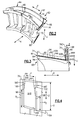
- Figure 3 illustrates the detail of a featherseal slot 82 formed in the circumferential face 78. It should be understood that a corresponding featherseal slot would be formed in the circumferential face 80, and in the circumferential faces of the adjacent components.
- the featherseal slot 82 begins at a fore face 84 of the outer platform 68, and includes an axial portion 86 extending toward the aft flange 76.
- the featherseal slot 82 further includes two radial portions 88, 90 extending radially into the aft flange 76 from the axial portion 86.
- the featherseal slot 82 is axially open at the fore face 84 and radially open at a radially outer surface 760 of the aft flange 76.
- the featherseal slot 82 need not be open in these locations, however.
- the featherseal slot 82 is shown in the outer platform 68, this disclosure is not limited to outer platforms. A similar featherseal slot 82 could be provided in the inner platform 66.
- first and second featherseals 92, 94 are provided in the featherseal slot 82.
- the first and second featherseals 92, 94 are retained in the featherseal slot 82 by way of a pressure differential between the radial sides of the first and second featherseals 92, 94.
- the first featherseal 92 is provided radially outward of the second seal 94.
- Each of the featherseals 92, 94 include an axial portion 92A, 94A within the axial portion 86 of the featherseal slot 82, and a radial portion 92R, 94R within respective radial portions 88, 90 of the featherseal slot 82.
- the featherseals 92, 94 further include a bend 92B, 94B between the axial and radial portions.
- each of the first and second featherseals 92, 94 are provided by a single, monolithic structure. That is, one structure provides the first featherseal 92, and another, separate structure provides the second featherseal 94.
- the featherseals 92, 94 are each provided by a respective, single piece of metallic material that is machined and bent (e.g., at the bends 92B, 94B) to provide the axial portions 92A, 94A and the radial portions 92R, 94R.
- the use of a single structure prevents leakage that may be caused by having separate axial and radial portions.
- featherseals 92A, 94A are illustrated, this disclosure extends to examples with only one featherseal, or with more than two featherseals. In those cases, there would be a corresponding number of radial portions 88, 90 within the featherseal slot 82. While this disclosure could extend to assemblies with only one featherseal, the redundancy of at least two featherseals increases resistance to leakage.
- Figure 4 illustrates the radial portion 90 of the featherseal slot 82 and a radial portion 90' of the featherseal slot of an adjacent doublet. As illustrated, the radial portion 94R of the second featherseal 94 is received within the radial portions 90, 90' of the adjacent featherseal slots, and spans a gap between the adjacent doublets.
- the radial portion 94 includes first and second opposed circumferential sides 96, 98.
- each of the circumferential sides 96, 98 includes a tapered section 96T, 98T. While each of the circumferential sides 96, 98 includes a taper in the example of Figure 4 , it should be understood that this disclosure also extends to featherseals having a radial portion with only one circumferential side having a taper.
- the tapered section 96T of the first circumferential side 96 begins at a distance R 1 radially outward of the axial portion 94A of the featherseal 94.
- the tapered section 96T follows a constant angle 100 relative to the edge of the non-tapered section (e.g., section overlapping R 1 ) of the first circumferential side 96. While the tapered section 96T follows a constant angle in this example, the angle could vary.
- the tapered section 96T could also be rounded or resemble a cut-out or notch, as examples.
- the tapered section 98T of the second circumferential side 98 begins at a distance R 2 radially outward of the axial portion 94A of the featherseal 94.
- the tapered section 98T of the second circumferential side 98 is tapered at a constant angle 102. As with the angle 100, the angle 102 could vary.
- R 1 is greater than R 2
- the angle 102 is greater than 100.
- the radial portion 94R of the featherseal 94 is asymmetrical. This disclosure is not limited to featherseals with asymmetrical radial portions, however.
- the asymmetry between the first and second circumferential edges 96, 98 may be particularly useful when there is a non-zero angle 104 between the axial portions (e.g., 86) of adjacent featherseal slots.
- the angle 104 may be intentional, or may be caused by a mismatch in the alignment between slots 90, 90' due to manufacturing tolerances, etc. In this example, the angle 104 is approximately 6.5 degrees.
- the angle 104 tips the radial portion 94R of the featherseal 94 circumferentially to the right.
- the taper is emphasized on the side of the featherseal 94 corresponding to the angle 104 (e.g., the right hand side in Figure 4 ).
- the taper 98T over a relatively large radial dimension of the second, right-hand (again, with reference to the Figure 4 orientation) circumferential side 98 prevents interference between the second circumferential side 98 and the featherseal slot 90' that would otherwise be caused by the circumferential tip of the featherseal 94.
- Such interference could potentially cause binding in the circumferential direction Y, which could twist the featherseal 94 and cause leakage.
- the arrangement of the radial portion 94R serves to prevent binding and reduce leakage between adjacent components.
- the dimension R which is the distance between the axial portion 94A and an end 94E of the radial portion 94R
- one arrangement that reduces leakage and prevents binding includes the distance R 1 being within a range of 0.62R-0.72R, and the distance R 2 being within a range of 0.38R-0.48R.
- the angle 100 is within a range of 7.9-8.1 degrees and the angle 102 is within a range of 8.2-8.4 degrees. While Figure 4 illustrates the featherseal 94 in detail, it should be understood that the featherseal 92 would be arranged similarly.
Landscapes
- Engineering & Computer Science (AREA)
- General Engineering & Computer Science (AREA)
- Mechanical Engineering (AREA)
- Physics & Mathematics (AREA)
- Geometry (AREA)
- Structures Of Non-Positive Displacement Pumps (AREA)
- Turbine Rotor Nozzle Sealing (AREA)
Abstract
Description
- Gas turbine engines typically include a compressor section, a combustor section and a turbine section. The compressor and turbine sections may include alternating series of rotating blades and stationary vanes that extend into the core flow path of the gas turbine engine. In order to prevent fluid leakage, featherseals may be provided between adjacent components near the core flow path boundary. For example, some known engines include featherseals that span a gap between adjacent stationary vanes.
- A section of a gas turbine engine according to an exemplary aspect of this disclosure includes, among other things, a vane assembly including a featherseal slot. The section further includes a featherseal at least partially received in the featherseal slot. The featherseal includes a radial portion having at least one tapered side.
- In a further non-limiting embodiment of the foregoing section, the featherseal slot is provided in a circumferential face of the vane assembly.
- In a further non-limiting embodiment of the foregoing section, the featherseal slot includes an axial portion and at least one radial portion.
- In a further non-limiting embodiment of the foregoing section, the featherseal slot includes first and second radial portions.
- In a further non-limiting embodiment of the foregoing section, the section includes first and second featherseals received in the featherseal slot. Further, each of the first and second featherseals has an axial portion provided in the axial portion of the featherseal slot, and a radial portion provided in a respective one of the first and second radial portions of the featherseal slot.
- In a further non-limiting embodiment of the foregoing section, the radial portions of the first and second featherseals have at least one tapered side.
- In a further non-limiting embodiment of the foregoing section, the radial portions of the first and second featherseals are asymmetrical, and a taper is emphasized on one of the first and second featherseals corresponding to a circumferential tip of the featherseal.
- In a further non-limiting embodiment of the foregoing section, a first monolithic structure provides both the axial portion and the radial portion of the first featherseal, and a second monolithic structure provides both the axial portion and the radial portion of the second featherseal. The first monolithic structure is separate from the second monolithic structure.
- In a further non-limiting embodiment of the foregoing section, the radial portion has opposed first and second circumferential sides, and each of the first and second circumferential sides has a taper. The taper of one of the first and second circumferential sides being emphasized to correspond to a circumferential tip of the featherseal.
- In a further non-limiting embodiment of the foregoing section, the radial portion of the featherseal extends outward from the axial portion of the featherseal to the end of the radial portion by a radial distance, a taper of the first circumferential side begins within a range of 0.62-0.72 of the radial distance and extends to the end of the radial portion, and a taper of the second circumferential side begins within a range of 0.38-0.48 of the radial distance and extends to the end of the radial portion.
- In a further non-limiting embodiment of the foregoing section, the taper of the first circumferential side is provided by a first angle and the taper of the second circumferential side is provided by a second angle different in magnitude than the first angle.
- In a further non-limiting embodiment of the foregoing section, the first angle is within a range of 7.9-8.1 degrees and the second angle is within a range of 8.2-8.4 degrees.
- A featherseal of a gas turbine engine according to an exemplary aspect of this disclosure includes, among other things, an axial portion, and a radial portion with at least one tapered side corresponding to a circumferential tip of the featherseal.
- In a further non-limiting embodiment of the foregoing featherseal, the radial portion has opposed first and second circumferential sides, and wherein each of the first and second circumferential sides has a taper.
- In a further non-limiting embodiment of the foregoing featherseal, the radial portion is asymmetrical.
- In a further non-limiting embodiment of the foregoing featherseal, the radial portion of the featherseal extends outward from the axial portion of the featherseal to an end of the radial portion by a radial distance, a taper of the first circumferential side begins within a range of 0.62-0.72 of the radial distance and extends to the end of the radial portion, and a taper of the second circumferential side begins within a range of 0.38-0.48 of the radial distance and extends to the end of the radial portion.
- In a further non-limiting embodiment of the foregoing featherseal, the taper of the first circumferential side is provided by a first constant angle, and the taper of the second circumferential side is provided by a second constant angle different in magnitude than the first constant angle.
- In a further non-limiting embodiment of the foregoing featherseal, the first constant angle is within a range of 7.9-8.1 degrees and the second constant angle is within a range of 8.2-8.4 degrees.
- In a further non-limiting embodiment of the foregoing featherseal, a single, monolithic structure provides both the axial portion and the radial portion of the featherseal.
- In a further non-limiting embodiment of the foregoing featherseal, the monolithic structure includes a bend between the axial portion and the radial portion of the featherseal.
- The embodiments, examples and alternatives of the preceding paragraphs, the claims, or the following description and drawings, including any of their various aspects or respective individual features, may be taken independently or in any combination. Features described in connection with one embodiment are applicable to all embodiments, unless such features are incompatible.
- The drawings can be briefly described as follows:
-
Figure 1 schematically illustrates an example gas turbine engine. -
Figure 2 is perspective view of an example airfoil assembly. -
Figure 3 is a view taken along line 3-3 ofFigure 2 , and illustrates two featherseals provided within a featherseal slot. -
Figure 4 is a view taken along line 4-4 ofFigure 3 , and illustrates the detail of a radial portion a featherseal. -
Figure 1 schematically illustrates agas turbine engine 20. Thegas turbine engine 20 is disclosed herein as a two-spool turbofan that generally incorporates a fan section 22, acompressor section 24, acombustor section 26 and aturbine section 28. Alternative engines might include an augmentor section (not shown) among other systems or features. The fan section 22 drives air along a bypass flow path B in a bypass duct defined within a nacelle 15, while thecompressor section 24 drives air along a core airflow path C for compression and communication into thecombustor section 26 then expansion through theturbine section 28. Although depicted as a two-spool turbofan gas turbine engine in the disclosed non-limiting embodiment, it should be understood that the concepts described herein are not limited to use with two-spool turbofans as the teachings may be applied to other types of turbine engines including three-spool architectures. - The
exemplary engine 20 generally includes alow speed spool 30 and ahigh speed spool 32 mounted for rotation about an engine central longitudinal axis X relative to an enginestatic structure 36 viaseveral bearing systems 38. It should be understood thatvarious bearing systems 38 at various locations may alternatively or additionally be provided, and the location ofbearing systems 38 may be varied as appropriate to the application. - The
low speed spool 30 generally includes aninner shaft 40 that interconnects afan 42, a first (or low)pressure compressor 44 and a first (or low)pressure turbine 46. Theinner shaft 40 is connected to thefan 42 through a speed change mechanism, which in exemplarygas turbine engine 20 is illustrated as a gearedarchitecture 48 to drive thefan 42 at a lower speed than thelow speed spool 30. Thehigh speed spool 32 includes anouter shaft 50 that interconnects a second (or high)pressure compressor 52 and a second (or high) pressure turbine 54. Acombustor 56 is arranged inexemplary gas turbine 20 between thehigh pressure compressor 52 and the high pressure turbine 54. Amid-turbine frame 57 of the enginestatic structure 36 is arranged generally between the high pressure turbine 54 and thelow pressure turbine 46. Themid-turbine frame 57 further supports bearingsystems 38 in theturbine section 28. Theinner shaft 40 and theouter shaft 50 are concentric and rotate viabearing systems 38 about the engine central longitudinal axis X which is collinear with their longitudinal axes. - The core airflow is compressed by the
low pressure compressor 44 then thehigh pressure compressor 52, mixed and burned with fuel in thecombustor 56, then expanded over the high pressure turbine 54 andlow pressure turbine 46. Themid-turbine frame 57 includesairfoils 59 which are in the core airflow path C. Theturbines 46, 54 rotationally drive the respectivelow speed spool 30 andhigh speed spool 32 in response to the expansion. It will be appreciated that each of the positions of the fan section 22,compressor section 24,combustor section 26,turbine section 28, and fandrive gear system 48 may be varied. For example,gear system 48 may be located aft ofcombustor section 26 or even aft ofturbine section 28, and fan section 22 may be positioned forward or aft of the location ofgear system 48. - The
engine 20 in one example is a high-bypass geared aircraft engine. In a further example, theengine 20 bypass ratio is greater than about six (6), with an example embodiment being greater than about ten (10), the gearedarchitecture 48 is an epicyclic gear train, such as a planetary gear system or other gear system, with a gear reduction ratio of greater than about 2.3 and thelow pressure turbine 46 has a pressure ratio that is greater than about five. In one disclosed embodiment, theengine 20 bypass ratio is greater than about ten (10:1), the fan diameter is significantly larger than that of thelow pressure compressor 44, and thelow pressure turbine 46 has a pressure ratio that is greater than about five 5:1.Low pressure turbine 46 pressure ratio is pressure measured prior to inlet oflow pressure turbine 46 as related to the pressure at the outlet of thelow pressure turbine 46 prior to an exhaust nozzle. The gearedarchitecture 48 may be an epicycle gear train, such as a planetary gear system or other gear system, with a gear reduction ratio of greater than about 2.3:1. It should be understood, however, that the above parameters are only exemplary of one embodiment of a geared architecture engine and that the present invention is applicable to other gas turbine engines including direct drive turbofans. -
Figure 2 illustrates an airfoil assembly 60 for use within agas turbine engine 20. The airfoil assembly 60 may be used in a number of engine locations, including the high pressure turbine 54. In this example, the airfoil assembly 60 is a stator vane assembly having first andsecond doublets second doublets doublets - This disclosure is not limited to doublets, and extends to other stator vane assemblies. For example, a "singlet" would include a single airfoil section, and a "triplet" would include three airfoil sections. Additionally, while the figures show stator vanes, the featherseal discussed herein could be used with other types of engine components.
- The
first doublet 62 includes aninner platform 66 and anouter platform 68 radially spaced (in the radial direction Z) apart from one another by first andsecond airfoil sections 70, 72. Theouter platform 68 includes afore flange 74 and anaft flange 76. Theouter platform 68 further includes a firstcircumferential face 78 and a second, opposedcircumferential face 80. It should be understood that thesecond doublet 64 is arranged similar to thefirst doublet 62. - In order to prevent fluid leakage between the adjacent platforms, at least one featherseal is provided in a featherseal slot formed into the circumferential faces 78, 80.
Figure 3 , for example, illustrates the detail of afeatherseal slot 82 formed in thecircumferential face 78. It should be understood that a corresponding featherseal slot would be formed in thecircumferential face 80, and in the circumferential faces of the adjacent components. - With reference to
Figure 3 , thefeatherseal slot 82 begins at afore face 84 of theouter platform 68, and includes an axial portion 86 extending toward theaft flange 76. Thefeatherseal slot 82 further includes tworadial portions aft flange 76 from the axial portion 86. - The
featherseal slot 82 is axially open at thefore face 84 and radially open at a radiallyouter surface 760 of theaft flange 76. Thefeatherseal slot 82 need not be open in these locations, however. Further, while thefeatherseal slot 82 is shown in theouter platform 68, this disclosure is not limited to outer platforms. Asimilar featherseal slot 82 could be provided in theinner platform 66. - In this example, first and
second featherseals featherseal slot 82. The first andsecond featherseals featherseal slot 82 by way of a pressure differential between the radial sides of the first andsecond featherseals - In this example, the
first featherseal 92 is provided radially outward of thesecond seal 94. Each of thefeatherseals axial portion featherseal slot 82, and aradial portion 92R, 94R within respectiveradial portions featherseal slot 82. Thefeatherseals bend - In this example, each of the first and
second featherseals first featherseal 92, and another, separate structure provides thesecond featherseal 94. In one example, thefeatherseals bends axial portions radial portions 92R, 94R. The use of a single structure prevents leakage that may be caused by having separate axial and radial portions. - Further, while two
featherseals radial portions featherseal slot 82. While this disclosure could extend to assemblies with only one featherseal, the redundancy of at least two featherseals increases resistance to leakage. -
Figure 4 illustrates theradial portion 90 of thefeatherseal slot 82 and a radial portion 90' of the featherseal slot of an adjacent doublet. As illustrated, theradial portion 94R of thesecond featherseal 94 is received within theradial portions 90, 90' of the adjacent featherseal slots, and spans a gap between the adjacent doublets. - The
radial portion 94 includes first and second opposedcircumferential sides circumferential sides section circumferential sides Figure 4 , it should be understood that this disclosure also extends to featherseals having a radial portion with only one circumferential side having a taper. - In this example, the tapered
section 96T of the firstcircumferential side 96 begins at a distance R1 radially outward of theaxial portion 94A of thefeatherseal 94. The taperedsection 96T follows aconstant angle 100 relative to the edge of the non-tapered section (e.g., section overlapping R1) of the firstcircumferential side 96. While the taperedsection 96T follows a constant angle in this example, the angle could vary. The taperedsection 96T could also be rounded or resemble a cut-out or notch, as examples. - The tapered
section 98T of the secondcircumferential side 98 begins at a distance R2 radially outward of theaxial portion 94A of thefeatherseal 94. The taperedsection 98T of the secondcircumferential side 98 is tapered at aconstant angle 102. As with theangle 100, theangle 102 could vary. - In the example of
Figure 4 , R1 is greater than R2, and theangle 102 is greater than 100. Thus, theradial portion 94R of thefeatherseal 94 is asymmetrical. This disclosure is not limited to featherseals with asymmetrical radial portions, however. - The asymmetry between the first and second
circumferential edges non-zero angle 104 between the axial portions (e.g., 86) of adjacent featherseal slots. Theangle 104 may be intentional, or may be caused by a mismatch in the alignment betweenslots 90, 90' due to manufacturing tolerances, etc. In this example, theangle 104 is approximately 6.5 degrees. - With reference to the orientation of
Figure 4 , theangle 104 tips theradial portion 94R of thefeatherseal 94 circumferentially to the right. Thus, on the side of the featherseal 94 corresponding to the angle 104 (e.g., the right hand side inFigure 4 ), the taper is emphasized. For example, providing thetaper 98T over a relatively large radial dimension of the second, right-hand (again, with reference to theFigure 4 orientation)circumferential side 98 prevents interference between the secondcircumferential side 98 and the featherseal slot 90' that would otherwise be caused by the circumferential tip of thefeatherseal 94. Such interference could potentially cause binding in the circumferential direction Y, which could twist the featherseal 94 and cause leakage. - The arrangement of the
radial portion 94R serves to prevent binding and reduce leakage between adjacent components. Relative to the dimension R, which is the distance between theaxial portion 94A and an end 94E of theradial portion 94R, one arrangement that reduces leakage and prevents binding includes the distance R1 being within a range of 0.62R-0.72R, and the distance R2 being within a range of 0.38R-0.48R. Further, in the example, theangle 100 is within a range of 7.9-8.1 degrees and theangle 102 is within a range of 8.2-8.4 degrees. WhileFigure 4 illustrates the featherseal 94 in detail, it should be understood that thefeatherseal 92 would be arranged similarly. - It should be understood that terms such as "fore," "aft," "axial," "radial," and "circumferential" are used above with reference to the normal operational attitude of the
engine 20. Further, these terms have been used herein for purposes of explanation, and should not be considered otherwise limiting. Terms such as "generally," "substantially," and "about" are not intended to be boundaryless terms, and should be interpreted consistent with the way one skilled in the art would interpret the term. - Although the different examples have the specific components shown in the illustrations, embodiments of this disclosure are not limited to those particular combinations. It is possible to use some of the components or features from one of the examples in combination with features or components from another one of the examples.
- One of ordinary skill in this art would understand that the above-described embodiments are exemplary and non-limiting. That is, modifications of this disclosure would come within the scope of the claims. Accordingly, the following claims should be studied to determine their true scope and content.
Claims (15)
- A section of a gas turbine engine (20), comprising:a vane assembly (60) including a featherseal slot (82); anda featherseal (92, 94) at least partially received in the featherseal slot (82), the featherseal (92, 94) including a radial portion (92R, 94R) having at least one tapered side.
- The section as recited in claim 1, wherein the featherseal slot (82) is provided in a circumferential face (78, 80) of the vane assembly (60).
- The section as recited in claim 1 or 2, wherein the featherseal slot (82) includes an axial portion (86) and at least one radial portion (88, 90).
- The section as recited in claim 3, wherein the featherseal slot (82) includes first and second radial portions (88, 90).
- The section as recited in claim 4, further comprising first and second featherseals (92, 94) received in the featherseal slot (82), wherein each of the first and second featherseals (92, 94) has an axial portion (92A, 94A) provided in the axial portion (86) of the featherseal slot (82), and a radial portion (92R, 94R) provided in a respective one of the first and second radial portions (88, 90) of the featherseal slot (82).
- The section as recited in claim 5, wherein the radial portions (92R, 94R) of the first and second featherseals (92, 94) have at least one tapered side.
- The section as recited in claim 5 or 6, wherein the radial portions (92R, 94R) of the first and second featherseals (92, 94) are asymmetrical, and wherein a taper is emphasized on one of the first and second featherseals (92, 94) corresponding to a circumferential tip of the featherseal (92, 94).
- The section as recited in claims 5, 6 or 7, wherein a first monolithic structure provides both the axial portion (92A) and the radial portion (92R) of the first featherseal (92), and wherein a second monolithic structure provides both the axial portion (94A) and the radial portion (94R) of the second featherseal (94), the first monolithic structure separate from the second monolithic structure.
- The section as recited in any of claims 1 to 5, wherein the radial portion (92R, 94R) has opposed first and second circumferential sides (96, 98), each of the first and second circumferential sides (96, 98) having a taper (96T, 98T), the taper (96T, 98T) of one of the first and second circumferential sides (96, 98) being emphasized to correspond to a circumferential tip of the featherseal (92, 94).
- A featherseal (92, 94), comprising:an axial portion (92A, 94A); anda radial portion (92R, 94R) with at least one tapered side corresponding to a circumferential tip of the featherseal (92, 94).
- The featherseal (92, 94) as recited in claim 10, wherein the radial portion 992R, 94R) has opposed first and second circumferential sides (96, 98), and wherein each of the first and second circumferential sides (96, 98) has a taper (96T, 98T).
- The featherseal (92, 94) as recited in claim 11, wherein the radial portion (92R, 94R) is asymmetrical.
- The featherseal (92, 94) as recited in claim 10, 11 or 12, wherein a single, monolithic structure provides both the axial portion (92A, 94A) and the radial portion (92R, 94R) of the featherseal (92, 94), optionally wherein the monolithic structure includes a bend (92B, 94B) between the axial portion (92A, 94A) and the radial portion (92R, 94R) of the featherseal (92, 94).
- The section or featherseal (92, 94) as recited in any of claims 9, 11, 12 or 13, wherein:the radial portion (92R, 94R) of the featherseal (92, 94) extends outward from the axial portion (92A, 94A) of the featherseal (92, 94) to the end of the radial portion (92R, 94R) by a radial distance;a taper (96T) of the first circumferential side (96) begins within a range of 0.62-0.72 of the radial distance and extends to the end of the radial portion (92R, 94R); anda taper (98T) of the second circumferential side (98) begins within a range of 0.38-0.48 of the radial distance and extends to the end of the radial portion (92R, 94R).
- The section or feather seal (92,94) as recited in claim 14, wherein the taper (96T) of the first circumferential side (96) is provided by a first angle (100) and the taper (98T) of the second circumferential side (98) is provided by a second angle (102) different in magnitude than the first angle (100), optionally wherein the first angle (100) is within a range of 7.9-8.1 degrees and the second angle (102) is within a range of 8.2-8.4 degrees.
Applications Claiming Priority (1)
| Application Number | Priority Date | Filing Date | Title |
|---|---|---|---|
| US201462093006P | 2014-12-17 | 2014-12-17 |
Publications (2)
| Publication Number | Publication Date |
|---|---|
| EP3034805A1 true EP3034805A1 (en) | 2016-06-22 |
| EP3034805B1 EP3034805B1 (en) | 2019-11-13 |
Family
ID=54850260
Family Applications (1)
| Application Number | Title | Priority Date | Filing Date |
|---|---|---|---|
| EP15200752.2A Active EP3034805B1 (en) | 2014-12-17 | 2015-12-17 | Featherseal having a tapered radial portion and gas turbine engine section comprising such a feather seal |
Country Status (2)
| Country | Link |
|---|---|
| US (1) | US10196913B1 (en) |
| EP (1) | EP3034805B1 (en) |
Cited By (2)
| Publication number | Priority date | Publication date | Assignee | Title |
|---|---|---|---|---|
| EP3309362A1 (en) * | 2016-10-17 | 2018-04-18 | United Technologies Corporation | Stator vane rail |
| US20200248566A1 (en) * | 2019-02-05 | 2020-08-06 | United Technologies Corporation | Feather seals with leakage metering |
Families Citing this family (2)
| Publication number | Priority date | Publication date | Assignee | Title |
|---|---|---|---|---|
| US11111802B2 (en) * | 2019-05-01 | 2021-09-07 | Raytheon Technologies Corporation | Seal for a gas turbine engine |
| US12234735B1 (en) | 2024-01-31 | 2025-02-25 | Rtx Corporation | CMC BOAS with overlapping seals |
Citations (4)
| Publication number | Priority date | Publication date | Assignee | Title |
|---|---|---|---|---|
| US20110206501A1 (en) * | 2010-02-24 | 2011-08-25 | Bergman Russell J | Combined featherseal slot and lightening pocket |
| US20130089414A1 (en) * | 2011-10-05 | 2013-04-11 | Rolls-Royce Plc | Strip seals |
| WO2014001084A1 (en) * | 2012-06-26 | 2014-01-03 | Siemens Aktiengesellschaft | Platform seal strip, turbine blade assembly and method for assembling it |
| EP2886800A1 (en) * | 2013-12-18 | 2015-06-24 | Rolls-Royce Deutschland Ltd & Co KG | Guide vane assembly for a gas turbine and corresponding strip seal |
Family Cites Families (13)
| Publication number | Priority date | Publication date | Assignee | Title |
|---|---|---|---|---|
| US4524980A (en) | 1983-12-05 | 1985-06-25 | United Technologies Corporation | Intersecting feather seals for interlocking gas turbine vanes |
| US5154577A (en) | 1991-01-17 | 1992-10-13 | General Electric Company | Flexible three-piece seal assembly |
| US5738490A (en) * | 1996-05-20 | 1998-04-14 | Pratt & Whitney Canada, Inc. | Gas turbine engine shroud seals |
| US5868398A (en) | 1997-05-20 | 1999-02-09 | United Technologies Corporation | Gas turbine stator vane seal |
| US20030039542A1 (en) | 2001-08-21 | 2003-02-27 | Cromer Robert Harold | Transition piece side sealing element and turbine assembly containing such seal |
| US6672829B1 (en) * | 2002-07-16 | 2004-01-06 | General Electric Company | Turbine blade having angled squealer tip |
| WO2004074640A1 (en) | 2003-02-19 | 2004-09-02 | Alstom Technology Ltd | Sealing arrangement, particularly for the blade segments of gas turbines |
| US7600967B2 (en) * | 2005-07-30 | 2009-10-13 | United Technologies Corporation | Stator assembly, module and method for forming a rotary machine |
| US7798768B2 (en) | 2006-10-25 | 2010-09-21 | Siemens Energy, Inc. | Turbine vane ID support |
| US8240985B2 (en) | 2008-04-29 | 2012-08-14 | Pratt & Whitney Canada Corp. | Shroud segment arrangement for gas turbine engines |
| JP5384983B2 (en) * | 2009-03-27 | 2014-01-08 | 本田技研工業株式会社 | Turbine shroud |
| US8753073B2 (en) * | 2010-06-23 | 2014-06-17 | General Electric Company | Turbine shroud sealing apparatus |
| US8784041B2 (en) * | 2011-08-31 | 2014-07-22 | Pratt & Whitney Canada Corp. | Turbine shroud segment with integrated seal |
-
2015
- 2015-12-17 US US14/973,040 patent/US10196913B1/en active Active
- 2015-12-17 EP EP15200752.2A patent/EP3034805B1/en active Active
Patent Citations (4)
| Publication number | Priority date | Publication date | Assignee | Title |
|---|---|---|---|---|
| US20110206501A1 (en) * | 2010-02-24 | 2011-08-25 | Bergman Russell J | Combined featherseal slot and lightening pocket |
| US20130089414A1 (en) * | 2011-10-05 | 2013-04-11 | Rolls-Royce Plc | Strip seals |
| WO2014001084A1 (en) * | 2012-06-26 | 2014-01-03 | Siemens Aktiengesellschaft | Platform seal strip, turbine blade assembly and method for assembling it |
| EP2886800A1 (en) * | 2013-12-18 | 2015-06-24 | Rolls-Royce Deutschland Ltd & Co KG | Guide vane assembly for a gas turbine and corresponding strip seal |
Cited By (4)
| Publication number | Priority date | Publication date | Assignee | Title |
|---|---|---|---|---|
| EP3309362A1 (en) * | 2016-10-17 | 2018-04-18 | United Technologies Corporation | Stator vane rail |
| US10557360B2 (en) | 2016-10-17 | 2020-02-11 | United Technologies Corporation | Vane intersegment gap sealing arrangement |
| US20200248566A1 (en) * | 2019-02-05 | 2020-08-06 | United Technologies Corporation | Feather seals with leakage metering |
| US11111794B2 (en) * | 2019-02-05 | 2021-09-07 | United Technologies Corporation | Feather seals with leakage metering |
Also Published As
| Publication number | Publication date |
|---|---|
| EP3034805B1 (en) | 2019-11-13 |
| US10196913B1 (en) | 2019-02-05 |
Similar Documents
| Publication | Publication Date | Title |
|---|---|---|
| US10890079B2 (en) | Gas turbine engine arc segments with arced walls | |
| US10633994B2 (en) | Feather seal assembly | |
| US10036259B2 (en) | Turbine blade having film cooling hole arrangement | |
| US10060268B2 (en) | Turbine blade having film cooling hole arrangement | |
| US20140212297A1 (en) | Gas turbine engine serpentine cooling passage with chevrons | |
| US10053992B2 (en) | Gas turbine engine airfoil squealer pocket cooling hole configuration | |
| US10443421B2 (en) | Turbomachine blade assemblies | |
| EP3034805B1 (en) | Featherseal having a tapered radial portion and gas turbine engine section comprising such a feather seal | |
| US20140219813A1 (en) | Gas turbine engine serpentine cooling passage | |
| EP3461993A1 (en) | Gas turbine engine airfoil | |
| EP3498978B1 (en) | Gas turbine engine vane with attachment hook | |
| EP3467260A1 (en) | Gas turbine engine airfoil with bowed tip | |
| US10502062B2 (en) | Integrally bladed rotor having axial arm and pocket | |
| EP2952693A2 (en) | Case with vane retention feature | |
| US20150300258A1 (en) | Cooling hole arrangement for engine component | |
| US20160201477A1 (en) | Gas turbine engine airfoil crossover and pedestal rib cooling arrangement | |
| EP2961964B1 (en) | Gas turbine engine component and corresponding method of manufacturing an aperture | |
| EP3470627B1 (en) | Gas turbine engine airfoil | |
| EP2986823B1 (en) | Airfoil component | |
| EP3477055A1 (en) | Gas turbine engine airfoil | |
| EP3550105B1 (en) | Gas turbine engine rotor disk | |
| EP2918782A1 (en) | Component with cooling hole having helical groove and corresponding gas turbine engine | |
| US20120070297A1 (en) | Aft loaded airfoil |
Legal Events
| Date | Code | Title | Description |
|---|---|---|---|
| PUAI | Public reference made under article 153(3) epc to a published international application that has entered the european phase |
Free format text: ORIGINAL CODE: 0009012 |
|
| AK | Designated contracting states |
Kind code of ref document: A1 Designated state(s): AL AT BE BG CH CY CZ DE DK EE ES FI FR GB GR HR HU IE IS IT LI LT LU LV MC MK MT NL NO PL PT RO RS SE SI SK SM TR |
|
| AX | Request for extension of the european patent |
Extension state: BA ME |
|
| RAP1 | Party data changed (applicant data changed or rights of an application transferred) |
Owner name: UNITED TECHNOLOGIES CORPORATION |
|
| STAA | Information on the status of an ep patent application or granted ep patent |
Free format text: STATUS: REQUEST FOR EXAMINATION WAS MADE |
|
| 17P | Request for examination filed |
Effective date: 20161222 |
|
| RBV | Designated contracting states (corrected) |
Designated state(s): AL AT BE BG CH CY CZ DE DK EE ES FI FR GB GR HR HU IE IS IT LI LT LU LV MC MK MT NL NO PL PT RO RS SE SI SK SM TR |
|
| RIC1 | Information provided on ipc code assigned before grant |
Ipc: F01D 11/00 20060101ALI20190418BHEP Ipc: F01D 9/04 20060101AFI20190418BHEP |
|
| GRAP | Despatch of communication of intention to grant a patent |
Free format text: ORIGINAL CODE: EPIDOSNIGR1 |
|
| STAA | Information on the status of an ep patent application or granted ep patent |
Free format text: STATUS: GRANT OF PATENT IS INTENDED |
|
| INTG | Intention to grant announced |
Effective date: 20190606 |
|
| GRAS | Grant fee paid |
Free format text: ORIGINAL CODE: EPIDOSNIGR3 |
|
| GRAA | (expected) grant |
Free format text: ORIGINAL CODE: 0009210 |
|
| STAA | Information on the status of an ep patent application or granted ep patent |
Free format text: STATUS: THE PATENT HAS BEEN GRANTED |
|
| AK | Designated contracting states |
Kind code of ref document: B1 Designated state(s): AL AT BE BG CH CY CZ DE DK EE ES FI FR GB GR HR HU IE IS IT LI LT LU LV MC MK MT NL NO PL PT RO RS SE SI SK SM TR |
|
| REG | Reference to a national code |
Ref country code: CH Ref legal event code: EP Ref country code: AT Ref legal event code: REF Ref document number: 1201854 Country of ref document: AT Kind code of ref document: T Effective date: 20191115 |
|
| REG | Reference to a national code |
Ref country code: DE Ref legal event code: R096 Ref document number: 602015041551 Country of ref document: DE |
|
| REG | Reference to a national code |
Ref country code: IE Ref legal event code: FG4D |
|
| REG | Reference to a national code |
Ref country code: NL Ref legal event code: MP Effective date: 20191113 |
|
| REG | Reference to a national code |
Ref country code: LT Ref legal event code: MG4D |
|
| PG25 | Lapsed in a contracting state [announced via postgrant information from national office to epo] |
Ref country code: LT Free format text: LAPSE BECAUSE OF FAILURE TO SUBMIT A TRANSLATION OF THE DESCRIPTION OR TO PAY THE FEE WITHIN THE PRESCRIBED TIME-LIMIT Effective date: 20191113 Ref country code: BG Free format text: LAPSE BECAUSE OF FAILURE TO SUBMIT A TRANSLATION OF THE DESCRIPTION OR TO PAY THE FEE WITHIN THE PRESCRIBED TIME-LIMIT Effective date: 20200213 Ref country code: FI Free format text: LAPSE BECAUSE OF FAILURE TO SUBMIT A TRANSLATION OF THE DESCRIPTION OR TO PAY THE FEE WITHIN THE PRESCRIBED TIME-LIMIT Effective date: 20191113 Ref country code: NL Free format text: LAPSE BECAUSE OF FAILURE TO SUBMIT A TRANSLATION OF THE DESCRIPTION OR TO PAY THE FEE WITHIN THE PRESCRIBED TIME-LIMIT Effective date: 20191113 Ref country code: SE Free format text: LAPSE BECAUSE OF FAILURE TO SUBMIT A TRANSLATION OF THE DESCRIPTION OR TO PAY THE FEE WITHIN THE PRESCRIBED TIME-LIMIT Effective date: 20191113 Ref country code: LV Free format text: LAPSE BECAUSE OF FAILURE TO SUBMIT A TRANSLATION OF THE DESCRIPTION OR TO PAY THE FEE WITHIN THE PRESCRIBED TIME-LIMIT Effective date: 20191113 Ref country code: PT Free format text: LAPSE BECAUSE OF FAILURE TO SUBMIT A TRANSLATION OF THE DESCRIPTION OR TO PAY THE FEE WITHIN THE PRESCRIBED TIME-LIMIT Effective date: 20200313 Ref country code: GR Free format text: LAPSE BECAUSE OF FAILURE TO SUBMIT A TRANSLATION OF THE DESCRIPTION OR TO PAY THE FEE WITHIN THE PRESCRIBED TIME-LIMIT Effective date: 20200214 Ref country code: NO Free format text: LAPSE BECAUSE OF FAILURE TO SUBMIT A TRANSLATION OF THE DESCRIPTION OR TO PAY THE FEE WITHIN THE PRESCRIBED TIME-LIMIT Effective date: 20200213 Ref country code: PL Free format text: LAPSE BECAUSE OF FAILURE TO SUBMIT A TRANSLATION OF THE DESCRIPTION OR TO PAY THE FEE WITHIN THE PRESCRIBED TIME-LIMIT Effective date: 20191113 |
|
| PG25 | Lapsed in a contracting state [announced via postgrant information from national office to epo] |
Ref country code: HR Free format text: LAPSE BECAUSE OF FAILURE TO SUBMIT A TRANSLATION OF THE DESCRIPTION OR TO PAY THE FEE WITHIN THE PRESCRIBED TIME-LIMIT Effective date: 20191113 Ref country code: IS Free format text: LAPSE BECAUSE OF FAILURE TO SUBMIT A TRANSLATION OF THE DESCRIPTION OR TO PAY THE FEE WITHIN THE PRESCRIBED TIME-LIMIT Effective date: 20200313 Ref country code: RS Free format text: LAPSE BECAUSE OF FAILURE TO SUBMIT A TRANSLATION OF THE DESCRIPTION OR TO PAY THE FEE WITHIN THE PRESCRIBED TIME-LIMIT Effective date: 20191113 |
|
| PG25 | Lapsed in a contracting state [announced via postgrant information from national office to epo] |
Ref country code: AL Free format text: LAPSE BECAUSE OF FAILURE TO SUBMIT A TRANSLATION OF THE DESCRIPTION OR TO PAY THE FEE WITHIN THE PRESCRIBED TIME-LIMIT Effective date: 20191113 |
|
| PG25 | Lapsed in a contracting state [announced via postgrant information from national office to epo] |
Ref country code: EE Free format text: LAPSE BECAUSE OF FAILURE TO SUBMIT A TRANSLATION OF THE DESCRIPTION OR TO PAY THE FEE WITHIN THE PRESCRIBED TIME-LIMIT Effective date: 20191113 Ref country code: RO Free format text: LAPSE BECAUSE OF FAILURE TO SUBMIT A TRANSLATION OF THE DESCRIPTION OR TO PAY THE FEE WITHIN THE PRESCRIBED TIME-LIMIT Effective date: 20191113 Ref country code: CZ Free format text: LAPSE BECAUSE OF FAILURE TO SUBMIT A TRANSLATION OF THE DESCRIPTION OR TO PAY THE FEE WITHIN THE PRESCRIBED TIME-LIMIT Effective date: 20191113 Ref country code: ES Free format text: LAPSE BECAUSE OF FAILURE TO SUBMIT A TRANSLATION OF THE DESCRIPTION OR TO PAY THE FEE WITHIN THE PRESCRIBED TIME-LIMIT Effective date: 20191113 Ref country code: DK Free format text: LAPSE BECAUSE OF FAILURE TO SUBMIT A TRANSLATION OF THE DESCRIPTION OR TO PAY THE FEE WITHIN THE PRESCRIBED TIME-LIMIT Effective date: 20191113 |
|
| REG | Reference to a national code |
Ref country code: CH Ref legal event code: PL |
|
| REG | Reference to a national code |
Ref country code: DE Ref legal event code: R097 Ref document number: 602015041551 Country of ref document: DE |
|
| REG | Reference to a national code |
Ref country code: AT Ref legal event code: MK05 Ref document number: 1201854 Country of ref document: AT Kind code of ref document: T Effective date: 20191113 |
|
| REG | Reference to a national code |
Ref country code: BE Ref legal event code: MM Effective date: 20191231 |
|
| PG25 | Lapsed in a contracting state [announced via postgrant information from national office to epo] |
Ref country code: SM Free format text: LAPSE BECAUSE OF FAILURE TO SUBMIT A TRANSLATION OF THE DESCRIPTION OR TO PAY THE FEE WITHIN THE PRESCRIBED TIME-LIMIT Effective date: 20191113 Ref country code: MC Free format text: LAPSE BECAUSE OF FAILURE TO SUBMIT A TRANSLATION OF THE DESCRIPTION OR TO PAY THE FEE WITHIN THE PRESCRIBED TIME-LIMIT Effective date: 20191113 Ref country code: SK Free format text: LAPSE BECAUSE OF FAILURE TO SUBMIT A TRANSLATION OF THE DESCRIPTION OR TO PAY THE FEE WITHIN THE PRESCRIBED TIME-LIMIT Effective date: 20191113 |
|
| PLBE | No opposition filed within time limit |
Free format text: ORIGINAL CODE: 0009261 |
|
| STAA | Information on the status of an ep patent application or granted ep patent |
Free format text: STATUS: NO OPPOSITION FILED WITHIN TIME LIMIT |
|
| 26N | No opposition filed |
Effective date: 20200814 |
|
| PG25 | Lapsed in a contracting state [announced via postgrant information from national office to epo] |
Ref country code: LU Free format text: LAPSE BECAUSE OF NON-PAYMENT OF DUE FEES Effective date: 20191217 Ref country code: IE Free format text: LAPSE BECAUSE OF NON-PAYMENT OF DUE FEES Effective date: 20191217 |
|
| PG25 | Lapsed in a contracting state [announced via postgrant information from national office to epo] |
Ref country code: CH Free format text: LAPSE BECAUSE OF NON-PAYMENT OF DUE FEES Effective date: 20191231 Ref country code: SI Free format text: LAPSE BECAUSE OF FAILURE TO SUBMIT A TRANSLATION OF THE DESCRIPTION OR TO PAY THE FEE WITHIN THE PRESCRIBED TIME-LIMIT Effective date: 20191113 Ref country code: BE Free format text: LAPSE BECAUSE OF NON-PAYMENT OF DUE FEES Effective date: 20191231 Ref country code: LI Free format text: LAPSE BECAUSE OF NON-PAYMENT OF DUE FEES Effective date: 20191231 Ref country code: AT Free format text: LAPSE BECAUSE OF FAILURE TO SUBMIT A TRANSLATION OF THE DESCRIPTION OR TO PAY THE FEE WITHIN THE PRESCRIBED TIME-LIMIT Effective date: 20191113 |
|
| PG25 | Lapsed in a contracting state [announced via postgrant information from national office to epo] |
Ref country code: IT Free format text: LAPSE BECAUSE OF FAILURE TO SUBMIT A TRANSLATION OF THE DESCRIPTION OR TO PAY THE FEE WITHIN THE PRESCRIBED TIME-LIMIT Effective date: 20191113 |
|
| PG25 | Lapsed in a contracting state [announced via postgrant information from national office to epo] |
Ref country code: CY Free format text: LAPSE BECAUSE OF FAILURE TO SUBMIT A TRANSLATION OF THE DESCRIPTION OR TO PAY THE FEE WITHIN THE PRESCRIBED TIME-LIMIT Effective date: 20191113 |
|
| PG25 | Lapsed in a contracting state [announced via postgrant information from national office to epo] |
Ref country code: MT Free format text: LAPSE BECAUSE OF FAILURE TO SUBMIT A TRANSLATION OF THE DESCRIPTION OR TO PAY THE FEE WITHIN THE PRESCRIBED TIME-LIMIT Effective date: 20191113 Ref country code: HU Free format text: LAPSE BECAUSE OF FAILURE TO SUBMIT A TRANSLATION OF THE DESCRIPTION OR TO PAY THE FEE WITHIN THE PRESCRIBED TIME-LIMIT; INVALID AB INITIO Effective date: 20151217 |
|
| PG25 | Lapsed in a contracting state [announced via postgrant information from national office to epo] |
Ref country code: TR Free format text: LAPSE BECAUSE OF FAILURE TO SUBMIT A TRANSLATION OF THE DESCRIPTION OR TO PAY THE FEE WITHIN THE PRESCRIBED TIME-LIMIT Effective date: 20191113 |
|
| PG25 | Lapsed in a contracting state [announced via postgrant information from national office to epo] |
Ref country code: MK Free format text: LAPSE BECAUSE OF FAILURE TO SUBMIT A TRANSLATION OF THE DESCRIPTION OR TO PAY THE FEE WITHIN THE PRESCRIBED TIME-LIMIT Effective date: 20191113 |
|
| REG | Reference to a national code |
Ref country code: DE Ref legal event code: R081 Ref document number: 602015041551 Country of ref document: DE Owner name: RAYTHEON TECHNOLOGIES CORPORATION (N.D.GES.D.S, US Free format text: FORMER OWNER: UNITED TECHNOLOGIES CORP., FARMINGTON, CONN., US Ref country code: DE Ref legal event code: R081 Ref document number: 602015041551 Country of ref document: DE Owner name: RTX CORPORATION (N.D.GES.D. STAATES DELAWARE),, US Free format text: FORMER OWNER: UNITED TECHNOLOGIES CORP., FARMINGTON, CONN., US |
|
| P01 | Opt-out of the competence of the unified patent court (upc) registered |
Effective date: 20230520 |
|
| REG | Reference to a national code |
Ref country code: DE Ref legal event code: R081 Ref document number: 602015041551 Country of ref document: DE Owner name: RTX CORPORATION (N.D.GES.D. STAATES DELAWARE),, US Free format text: FORMER OWNER: RAYTHEON TECHNOLOGIES CORPORATION (N.D.GES.D.STAATES DELAWARE), ARLINGTON, VA, US |
|
| PGFP | Annual fee paid to national office [announced via postgrant information from national office to epo] |
Ref country code: DE Payment date: 20251126 Year of fee payment: 11 |
|
| PGFP | Annual fee paid to national office [announced via postgrant information from national office to epo] |
Ref country code: GB Payment date: 20251119 Year of fee payment: 11 |
|
| PGFP | Annual fee paid to national office [announced via postgrant information from national office to epo] |
Ref country code: FR Payment date: 20251120 Year of fee payment: 11 |