EP3034786A2 - A gas turbine fan blade having a plurality of shear zones - Google Patents
A gas turbine fan blade having a plurality of shear zones Download PDFInfo
- Publication number
- EP3034786A2 EP3034786A2 EP15196976.3A EP15196976A EP3034786A2 EP 3034786 A2 EP3034786 A2 EP 3034786A2 EP 15196976 A EP15196976 A EP 15196976A EP 3034786 A2 EP3034786 A2 EP 3034786A2
- Authority
- EP
- European Patent Office
- Prior art keywords
- blade
- leading edge
- shear
- zones
- angled
- Prior art date
- Legal status (The legal status is an assumption and is not a legal conclusion. Google has not performed a legal analysis and makes no representation as to the accuracy of the status listed.)
- Granted
Links
Images


Classifications
-
- F—MECHANICAL ENGINEERING; LIGHTING; HEATING; WEAPONS; BLASTING
- F01—MACHINES OR ENGINES IN GENERAL; ENGINE PLANTS IN GENERAL; STEAM ENGINES
- F01D—NON-POSITIVE DISPLACEMENT MACHINES OR ENGINES, e.g. STEAM TURBINES
- F01D5/00—Blades; Blade-carrying members; Heating, heat-insulating, cooling or antivibration means on the blades or the members
- F01D5/12—Blades
- F01D5/14—Form or construction
- F01D5/147—Construction, i.e. structural features, e.g. of weight-saving hollow blades
-
- F—MECHANICAL ENGINEERING; LIGHTING; HEATING; WEAPONS; BLASTING
- F01—MACHINES OR ENGINES IN GENERAL; ENGINE PLANTS IN GENERAL; STEAM ENGINES
- F01D—NON-POSITIVE DISPLACEMENT MACHINES OR ENGINES, e.g. STEAM TURBINES
- F01D21/00—Shutting-down of machines or engines, e.g. in emergency; Regulating, controlling, or safety means not otherwise provided for
- F01D21/04—Shutting-down of machines or engines, e.g. in emergency; Regulating, controlling, or safety means not otherwise provided for responsive to undesired position of rotor relative to stator or to breaking-off of a part of the rotor, e.g. indicating such position
- F01D21/045—Shutting-down of machines or engines, e.g. in emergency; Regulating, controlling, or safety means not otherwise provided for responsive to undesired position of rotor relative to stator or to breaking-off of a part of the rotor, e.g. indicating such position special arrangements in stators or in rotors dealing with breaking-off of part of rotor
-
- F—MECHANICAL ENGINEERING; LIGHTING; HEATING; WEAPONS; BLASTING
- F01—MACHINES OR ENGINES IN GENERAL; ENGINE PLANTS IN GENERAL; STEAM ENGINES
- F01D—NON-POSITIVE DISPLACEMENT MACHINES OR ENGINES, e.g. STEAM TURBINES
- F01D5/00—Blades; Blade-carrying members; Heating, heat-insulating, cooling or antivibration means on the blades or the members
- F01D5/12—Blades
- F01D5/28—Selecting particular materials; Particular measures relating thereto; Measures against erosion or corrosion
- F01D5/282—Selecting composite materials, e.g. blades with reinforcing filaments
-
- F—MECHANICAL ENGINEERING; LIGHTING; HEATING; WEAPONS; BLASTING
- F02—COMBUSTION ENGINES; HOT-GAS OR COMBUSTION-PRODUCT ENGINE PLANTS
- F02C—GAS-TURBINE PLANTS; AIR INTAKES FOR JET-PROPULSION PLANTS; CONTROLLING FUEL SUPPLY IN AIR-BREATHING JET-PROPULSION PLANTS
- F02C7/00—Features, components parts, details or accessories, not provided for in, or of interest apart form groups F02C1/00 - F02C6/00; Air intakes for jet-propulsion plants
- F02C7/04—Air intakes for gas-turbine plants or jet-propulsion plants
- F02C7/05—Air intakes for gas-turbine plants or jet-propulsion plants having provisions for obviating the penetration of damaging objects or particles
-
- F—MECHANICAL ENGINEERING; LIGHTING; HEATING; WEAPONS; BLASTING
- F04—POSITIVE - DISPLACEMENT MACHINES FOR LIQUIDS; PUMPS FOR LIQUIDS OR ELASTIC FLUIDS
- F04D—NON-POSITIVE-DISPLACEMENT PUMPS
- F04D29/00—Details, component parts, or accessories
- F04D29/26—Rotors specially for elastic fluids
- F04D29/32—Rotors specially for elastic fluids for axial flow pumps
- F04D29/321—Rotors specially for elastic fluids for axial flow pumps for axial flow compressors
- F04D29/324—Blades
-
- F—MECHANICAL ENGINEERING; LIGHTING; HEATING; WEAPONS; BLASTING
- F05—INDEXING SCHEMES RELATING TO ENGINES OR PUMPS IN VARIOUS SUBCLASSES OF CLASSES F01-F04
- F05D—INDEXING SCHEME FOR ASPECTS RELATING TO NON-POSITIVE-DISPLACEMENT MACHINES OR ENGINES, GAS-TURBINES OR JET-PROPULSION PLANTS
- F05D2220/00—Application
- F05D2220/30—Application in turbines
- F05D2220/36—Application in turbines specially adapted for the fan of turbofan engines
-
- F—MECHANICAL ENGINEERING; LIGHTING; HEATING; WEAPONS; BLASTING
- F05—INDEXING SCHEMES RELATING TO ENGINES OR PUMPS IN VARIOUS SUBCLASSES OF CLASSES F01-F04
- F05D—INDEXING SCHEME FOR ASPECTS RELATING TO NON-POSITIVE-DISPLACEMENT MACHINES OR ENGINES, GAS-TURBINES OR JET-PROPULSION PLANTS
- F05D2230/00—Manufacture
- F05D2230/20—Manufacture essentially without removing material
- F05D2230/23—Manufacture essentially without removing material by permanently joining parts together
- F05D2230/232—Manufacture essentially without removing material by permanently joining parts together by welding
-
- F—MECHANICAL ENGINEERING; LIGHTING; HEATING; WEAPONS; BLASTING
- F05—INDEXING SCHEMES RELATING TO ENGINES OR PUMPS IN VARIOUS SUBCLASSES OF CLASSES F01-F04
- F05D—INDEXING SCHEME FOR ASPECTS RELATING TO NON-POSITIVE-DISPLACEMENT MACHINES OR ENGINES, GAS-TURBINES OR JET-PROPULSION PLANTS
- F05D2240/00—Components
- F05D2240/20—Rotors
- F05D2240/30—Characteristics of rotor blades, i.e. of any element transforming dynamic fluid energy to or from rotational energy and being attached to a rotor
- F05D2240/303—Characteristics of rotor blades, i.e. of any element transforming dynamic fluid energy to or from rotational energy and being attached to a rotor related to the leading edge of a rotor blade
-
- F—MECHANICAL ENGINEERING; LIGHTING; HEATING; WEAPONS; BLASTING
- F05—INDEXING SCHEMES RELATING TO ENGINES OR PUMPS IN VARIOUS SUBCLASSES OF CLASSES F01-F04
- F05D—INDEXING SCHEME FOR ASPECTS RELATING TO NON-POSITIVE-DISPLACEMENT MACHINES OR ENGINES, GAS-TURBINES OR JET-PROPULSION PLANTS
- F05D2250/00—Geometry
- F05D2250/30—Arrangement of components
- F05D2250/38—Arrangement of components angled, e.g. sweep angle
-
- F—MECHANICAL ENGINEERING; LIGHTING; HEATING; WEAPONS; BLASTING
- F05—INDEXING SCHEMES RELATING TO ENGINES OR PUMPS IN VARIOUS SUBCLASSES OF CLASSES F01-F04
- F05D—INDEXING SCHEME FOR ASPECTS RELATING TO NON-POSITIVE-DISPLACEMENT MACHINES OR ENGINES, GAS-TURBINES OR JET-PROPULSION PLANTS
- F05D2260/00—Function
- F05D2260/30—Retaining components in desired mutual position
- F05D2260/31—Retaining bolts or nuts
- F05D2260/311—Retaining bolts or nuts of the frangible or shear type
Definitions
- the present invention relates to a fan blade and/or a gas turbine engine.
- Gas turbine engines are typically employed to power aircraft.
- a gas turbine engine will comprise an axial fan driven by an engine core.
- the engine core is generally made up of one or more turbines which drive respective compressors via coaxial shafts.
- the fan is usually driven directly off an additional lower pressure turbine in the engine core.
- a fan of the gas turbine engine generally includes a plurality of blades mounted to a hub.
- a fan casing and liner circumscribe the fan blades.
- Fan blades may be metallic or have a composite construction.
- a composite fan blade will have a composite non-metallic core, e.g. a core having fibres within a resin matrix.
- a composite blade will have a metallic leading edge to prevent erosion and to protect the blade against impact damage from foreign objects.
- the metallic leading edge generally wraps around the leading edge of the composite core and covers a portion of the suction surface of the blade and a portion of the pressure surface of the blade.
- the construction of the leading edge means that it can apply high impact forces to the fan casing.
- the fan casing and liner can be designed to absorb the impact energy imparted by a released blade and leading edge. However, this generally leads to a heavy system that has associated efficiency penalties.
- a first aspect of the invention provides a turbomachine blade comprising blade tip and a metallic leading edge having a plurality of shear zones angled to the blade tip, wherein the shear strength of the shear zones is less than the shear strength of other regions of the leading edge.
- reference to an angled plane refers to an angle greater than 0°.
- the shear zones may be acutely or obtusely angled to the blade tip.
- shear planes means that in the event of an impact, shear can be initially initiated at the shear zones.
- the use of a plurality of shear zones promotes progressive collapse of the leading edge so as to increase energy absorption during a fan blade off event, which in turn reduces the loading requirements for the fan case.
- each shear zone is intended to shear so that the leading edge breaks up into multiple pieces so as to absorb impact energy.
- the shear zones may be angled in a plane defined by a spanwise and a chordwise direction of the blade.
- Each shear zone may define a slip plane.
- the slip plane may be angled.
- the shear strength of the shear zones may be less than the shear strength of the remainder of the leading edge.
- the blade may comprise a core.
- the core may be a composite core or a metallic core.
- the metallic leading edge may be provided at a leading edge or end of the core.
- the blade may have a leading edge and a trailing edge; and a suction surface extending between the leading edge and the trailing edge and a pressure surface extending between the leading edge and the trailing edge.
- a chordwise direction is a direction extending between the leading edge and the trailing edge;
- a spanwise direction is a direction extending between the tip of the blade and the root of the blade;
- the thickness direction is a direction extending between the pressure surface and the suction surface of the blade.
- the plurality of shear zones may be distributed along the leading edge in a spanwise direction.
- the zones may be angled towards a tip of the blade in a direction from the leading edge towards a trailing edge of the blade.
- the angle between the zones and the tip of the blade may be acute. That is, the angle from the zone to the tip in a clockwise direction may be acute.
- the zones may form an acute angle with a longitudinal axis of the turbomachine (e.g. the angle from the shear zone to the longitudinal axis in a clockwise direction may be acute).
- the zones may be angled such that, in use, the angle between the zones and the longitudinal axis of the turbomachine is equal to or between 30° and 80°. For example, equal to or less than 70° or equal to or more than 40°, e.g. 45° or 60°.
- the metallic leading edge may comprise a plurality of sections arranged and adjacently attached in a spanwise direction.
- the surfaces of the sections intended to be bonded to another section may be angled to an adjacent surface.
- the shear zones may include the bondline between the adjacently attached sections.
- the sections may be attached using an adhesive, metal bonding process, or mechanical connection.
- the sections may be welded together.
- One or more cavities may be provided in the shear zones.
- the leading edge may be thinner in a region of the shear zones compared to regions directly adjacent said shear zones.
- the shear zones may be each angled in a direction defined by a thickness direction and a spanwise direction.
- the metallic leading edge may include two wings and a fore portion provided between the two wings.
- the leading edge may be formed in two portions, the two portions being connected together in the fore portion.
- Each of the shear zones in the region of the wings may be angled in a direction defined by a thickness direction and a spanwise direction.
- the shear zones may be angled on each wing such that an innermost position of the shear zone is nearer to the blade tip than an outermost position.
- leading edge may be made by additive manufacture. Alternatively, by way of example only, the leading edge may be machined from solid, forged, cast or metal injection moulded.
- the metallic leading edge may comprise a plurality of sections arranged in a spanwise direction, the sections being connected together by a connection having a weaker shear strength than said sections, and the connection between the sections being angled to a tip of the blade.
- the surfaces of the sections intended to be bonded to an adjacent section may be angled to an adjacent side, such that the surface is angled to the blade tip.
- the sections may be welded together.
- a second aspect of the invention provides a gas turbine engine comprising a fan and a fan case that circumscribes the fan, wherein the fan comprises a plurality of blades according to the first aspect.
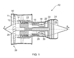
- a bypass gas turbine engine is indicated at 10.
- the engine 10 comprises, in axial flow series, an air intake duct 11, fan 12, a bypass duct 13, an intermediate pressure compressor 14, a high pressure compressor 16, a combustor 18, a high pressure turbine 20, an intermediate pressure turbine 22, a low pressure turbine 24 and an exhaust nozzle 25.
- the fan 12, compressors 14, 16 and turbines 20, 22, 24 all rotate about the major axis of the gas turbine engine 10 and so define the axial direction of the gas turbine engine.
- Air is drawn through the air intake duct 11 by the fan 12 where it is accelerated. A significant portion of the airflow is discharged through the bypass duct 13 generating a corresponding portion of the engine thrust. The remainder is drawn through the intermediate pressure compressor 14 into what is termed the core of the engine 10 where the air is compressed. A further stage of compression takes place in the high pressure compressor 16 before the air is mixed with fuel and burned in the combustor 18. The resulting hot working fluid is discharged through the high pressure turbine 20, the intermediate pressure turbine 22 and the low pressure turbine 24 in series where work is extracted from the working fluid. The work extracted drives the intake fan 12, the intermediate pressure compressor 14 and the high pressure compressor 16 via shafts 26, 28, 30. The working fluid, which has reduced in pressure and temperature, is then expelled through the exhaust nozzle 25 generating the remainder of the engine thrust.
- the intake fan 12 comprises an array of radially extending fan blades 40 that are mounted to the shaft 26.
- the shaft 26 may be considered a hub at the position where the fan blades 40 are mounted.
- the fan blades are circumscribed by a fan casing 39.
- the fan casing includes a liner proximal to the fan blades.
- a forward direction (indicated by arrow F in Figure 3 ) and a rearward direction (indicated by arrow R in Figure 3 ) are defined in terms of axial airflow through the engine 10.
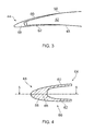
- the fan blades 40 each comprise an aerofoil portion or core 42 having a leading edge 44, a trailing edge 46, a concave pressure surface 48 extending from the leading edge to the trailing edge and a convex suction surface (not shown in Figure 2 but indicated at 50 in Figure 3 ) extending from the leading edge to the trailing edge.
- the fan blade has a root 52 via which the blade can be connected to the hub.
- the fan blade has a tip 56 at an opposing end to the root.
- the fan blade may also have an integral platform 54 which may be hollow or ribbed for out of plane bending stiffness.
- the fan blade includes a metallic leading edge 44 covering the leading edge of the core and extending along a portion of the pressure surface and suction surface of the core.
- the fan blade also includes a metallic trailing edge covering the trailing edge of the core and extending along a portion of the pressure surface and the suction surface of the core.
- a chordwise direction C is a direction extending between the leading edge and the trailing edge
- a spanwise direction S is a direction extending between the tip of the blade and the root 52 of the blade 40
- the thickness direction T is a direction extending between the pressure surface 48 and the suction surface 50 of the blade 40.
- the metallic leading edge 44 includes a fore portion 58 provided between two wings 60, 62.
- One of the wings 60 extends partially along the suction side of the core 42 and the other of the wings 62 extends partially along the pressure side of the core.
- the leading edge 44 includes a plurality of shear zones defining slip planes 70.
- slip planes are illustrated in Figure 4 , but the number of slip planes may be more or less than four, and the number of slip planes can be selected to promote the desired leading edge failure in the event of the fan blade being released from the fan during use.
- the slip planes extend the full chordal length of the leading edge, but in alternative embodiments the slip planes may be limited to the fore portion and a forward region of the wings.
- the slip planes 70 are angled to the root 52 or the tip 56 of the blade.
- the slip planes are angled towards the tip in a direction from the leading edge to the trailing edge, in this way, in use, the slip planes are acutely angled (indicated by angle ⁇ ) to an axis parallel to the longitudinal axis of the gas turbine engine 10.
- the angle of the slip planes can be selected to achieve the desired failure mode for a given blade and casing design.
- the slip planes 70 may be formed in a number of different ways.
- the leading edge 44 may be formed from a plurality of sections 72 adjacently stacked in a spanwise direction and attached (e.g. welded) together.
- the slip planes 70 may be defined by the bondline between the stacked sections.
- the bondline may be treated and/or may have a pattern of bonded and non-bonded areas so as to adapt the bondline to shear at a desired predetermined shear load.
- leading edge 44 may be thinned in the region of the slip planes 70.
- a groove 74 on the outer and/or inner surface of the leading edge may be provided.
- the weld relief (or weld preparation) may contribute to thinning the leading edge.
- the slip planes 70 may also be angled in a thickness direction.
- local thinning of the leading edge 44 e.g. by providing grooves 74 or cavities
- the slip planes are angled so that the slip plane on the inner side of each wing 60, 62 is angled towards the blade tip.
- the metallic leading edge 44 is formed of a first portion 64 and a second portion 66 connected together in a region of the fore portion 58.
- Each of the first portion and the second portion form one wing 60, 62 and part of the fore portion 58.
- the first portion and the second portion connect in a central region of the fore portion.
- the leading edge may be formed as a single component.
- the first portion and the second portion may be made using additive manufacture, machining from solid or any suitable metal forming method.
- the first portion may be bonded to the second portion using welding, e.g. electron beam welding, or diffusion bonding.
- the heat treatment applied to the weld may be selected so as to achieve the desired shear strength in the region of the weld.
- heat treatment may be omitted.
- leading edge is manufactured in two portions that are bonded together.
- leading edge may be made as a single component.
- leading edge may be manufactured using additive layer manufacture and the shear zones may be provided by including voids, cavities and/or thinned regions in the leading edge.
- leading edge has been shown as having two wings, but in alternative embodiments the leading edge may have a "bullet" shape, that is be shaped to exclude the wings.
- the fan blade described is a composite blade with a metallic leading edge.
- the leading edge may be a leading edge of a metallic blade (e.g. a solid or hollow metallic blade).
- the leading edge may be integrally formed with the core of the blade.
Landscapes
- Engineering & Computer Science (AREA)
- Chemical & Material Sciences (AREA)
- Mechanical Engineering (AREA)
- General Engineering & Computer Science (AREA)
- Combustion & Propulsion (AREA)
- Materials Engineering (AREA)
- Architecture (AREA)
- Composite Materials (AREA)
- Structures Of Non-Positive Displacement Pumps (AREA)
- Turbine Rotor Nozzle Sealing (AREA)
Abstract
Description
- The present invention relates to a fan blade and/or a gas turbine engine.
- Gas turbine engines are typically employed to power aircraft. Typically a gas turbine engine will comprise an axial fan driven by an engine core. The engine core is generally made up of one or more turbines which drive respective compressors via coaxial shafts. The fan is usually driven directly off an additional lower pressure turbine in the engine core.
- A fan of the gas turbine engine generally includes a plurality of blades mounted to a hub. A fan casing and liner circumscribe the fan blades. Fan blades may be metallic or have a composite construction. Generally a composite fan blade will have a composite non-metallic core, e.g. a core having fibres within a resin matrix. Typically a composite blade will have a metallic leading edge to prevent erosion and to protect the blade against impact damage from foreign objects. The metallic leading edge generally wraps around the leading edge of the composite core and covers a portion of the suction surface of the blade and a portion of the pressure surface of the blade.
- In the event of the leading edge becoming detached from the remainder of the fan blade (e.g. if a fan blade is released from the hub), the construction of the leading edge means that it can apply high impact forces to the fan casing. The fan casing and liner can be designed to absorb the impact energy imparted by a released blade and leading edge. However, this generally leads to a heavy system that has associated efficiency penalties.
- A first aspect of the invention provides a turbomachine blade comprising blade tip and a metallic leading edge having a plurality of shear zones angled to the blade tip, wherein the shear strength of the shear zones is less than the shear strength of other regions of the leading edge.
- In the present application, reference to an angled plane refers to an angle greater than 0°.
- The shear zones may be acutely or obtusely angled to the blade tip.
- The provision and angling of the shear planes means that in the event of an impact, shear can be initially initiated at the shear zones. The use of a plurality of shear zones promotes progressive collapse of the leading edge so as to increase energy absorption during a fan blade off event, which in turn reduces the loading requirements for the fan case. During progressive collapse of the leading edge, each shear zone is intended to shear so that the leading edge breaks up into multiple pieces so as to absorb impact energy.
- For example, the shear zones may be angled in a plane defined by a spanwise and a chordwise direction of the blade. Each shear zone may define a slip plane. The slip plane may be angled.
- The shear strength of the shear zones may be less than the shear strength of the remainder of the leading edge.
- The blade may comprise a core. The core may be a composite core or a metallic core. The metallic leading edge may be provided at a leading edge or end of the core.
- The blade may have a leading edge and a trailing edge; and a suction surface extending between the leading edge and the trailing edge and a pressure surface extending between the leading edge and the trailing edge. In the present application, a chordwise direction is a direction extending between the leading edge and the trailing edge; a spanwise direction is a direction extending between the tip of the blade and the root of the blade; and the thickness direction is a direction extending between the pressure surface and the suction surface of the blade.
- The plurality of shear zones may be distributed along the leading edge in a spanwise direction.
- The zones may be angled towards a tip of the blade in a direction from the leading edge towards a trailing edge of the blade. For example, the angle between the zones and the tip of the blade may be acute. That is, the angle from the zone to the tip in a clockwise direction may be acute. In use, the zones may form an acute angle with a longitudinal axis of the turbomachine (e.g. the angle from the shear zone to the longitudinal axis in a clockwise direction may be acute).
- The zones may be angled such that, in use, the angle between the zones and the longitudinal axis of the turbomachine is equal to or between 30° and 80°. For example, equal to or less than 70° or equal to or more than 40°, e.g. 45° or 60°.
- The metallic leading edge may comprise a plurality of sections arranged and adjacently attached in a spanwise direction. The surfaces of the sections intended to be bonded to another section may be angled to an adjacent surface.
- The shear zones may include the bondline between the adjacently attached sections. The sections may be attached using an adhesive, metal bonding process, or mechanical connection.
- The sections may be welded together.
- One or more cavities may be provided in the shear zones.
- The leading edge may be thinner in a region of the shear zones compared to regions directly adjacent said shear zones.
- The shear zones may be each angled in a direction defined by a thickness direction and a spanwise direction.
- The metallic leading edge may include two wings and a fore portion provided between the two wings.
- The leading edge may be formed in two portions, the two portions being connected together in the fore portion.
- Each of the shear zones in the region of the wings may be angled in a direction defined by a thickness direction and a spanwise direction.
- The shear zones may be angled on each wing such that an innermost position of the shear zone is nearer to the blade tip than an outermost position.
- The leading edge may be made by additive manufacture. Alternatively, by way of example only, the leading edge may be machined from solid, forged, cast or metal injection moulded.
- The metallic leading edge may comprise a plurality of sections arranged in a spanwise direction, the sections being connected together by a connection having a weaker shear strength than said sections, and the connection between the sections being angled to a tip of the blade.
- The surfaces of the sections intended to be bonded to an adjacent section may be angled to an adjacent side, such that the surface is angled to the blade tip.
- The sections may be welded together.
- A second aspect of the invention provides a gas turbine engine comprising a fan and a fan case that circumscribes the fan, wherein the fan comprises a plurality of blades according to the first aspect.
- The invention will now be described, by way of example only, with reference to the accompanying drawings in which:
-
Figure 1 illustrates a gas turbine engine; -
Figure 2 illustrates a composite fan blade; -
Figure 3 illustrates a partial cross section of the composite fan blade ofFigure 2 ; -
Figure 4 illustrates a section view of a leading edge of the fan blade ofFigure 2 ; -
Figure 5 illustrates a schematic of the fan blade ofFigure 2 viewed from the pressure side and illustrates the position of a plurality of shear zones; -
Figures 6 and 7 illustrate a partial sectional view of the leading edge ofFigure 4 along the line S-S; and -
Figure 8 illustrates a partial view of the leading edge ofFigure 7 in the direction of the arrow X. - With reference to
Figure 1 a bypass gas turbine engine is indicated at 10. Theengine 10 comprises, in axial flow series, anair intake duct 11,fan 12, abypass duct 13, anintermediate pressure compressor 14, ahigh pressure compressor 16, acombustor 18, ahigh pressure turbine 20, anintermediate pressure turbine 22, alow pressure turbine 24 and anexhaust nozzle 25. Thefan 12,compressors turbines gas turbine engine 10 and so define the axial direction of the gas turbine engine. - Air is drawn through the
air intake duct 11 by thefan 12 where it is accelerated. A significant portion of the airflow is discharged through thebypass duct 13 generating a corresponding portion of the engine thrust. The remainder is drawn through theintermediate pressure compressor 14 into what is termed the core of theengine 10 where the air is compressed. A further stage of compression takes place in thehigh pressure compressor 16 before the air is mixed with fuel and burned in thecombustor 18. The resulting hot working fluid is discharged through thehigh pressure turbine 20, theintermediate pressure turbine 22 and thelow pressure turbine 24 in series where work is extracted from the working fluid. The work extracted drives theintake fan 12, theintermediate pressure compressor 14 and thehigh pressure compressor 16 viashafts exhaust nozzle 25 generating the remainder of the engine thrust. - The
intake fan 12 comprises an array of radially extendingfan blades 40 that are mounted to theshaft 26. Theshaft 26 may be considered a hub at the position where thefan blades 40 are mounted. The fan blades are circumscribed by afan casing 39. The fan casing includes a liner proximal to the fan blades. - In the present application a forward direction (indicated by arrow F in
Figure 3 ) and a rearward direction (indicated by arrow R inFigure 3 ) are defined in terms of axial airflow through theengine 10. - Referring to
Figure 2 , thefan blades 40 each comprise an aerofoil portion orcore 42 having a leadingedge 44, a trailingedge 46, aconcave pressure surface 48 extending from the leading edge to the trailing edge and a convex suction surface (not shown inFigure 2 but indicated at 50 inFigure 3 ) extending from the leading edge to the trailing edge. The fan blade has aroot 52 via which the blade can be connected to the hub. The fan blade has atip 56 at an opposing end to the root. The fan blade may also have anintegral platform 54 which may be hollow or ribbed for out of plane bending stiffness. The fan blade includes a metallicleading edge 44 covering the leading edge of the core and extending along a portion of the pressure surface and suction surface of the core. The fan blade also includes a metallic trailing edge covering the trailing edge of the core and extending along a portion of the pressure surface and the suction surface of the core. - In the present application, a chordwise direction C is a direction extending between the leading edge and the trailing edge; a spanwise direction S is a direction extending between the tip of the blade and the
root 52 of theblade 40; and the thickness direction T is a direction extending between thepressure surface 48 and thesuction surface 50 of theblade 40. - Referring now to
Figure 3 and 4 , the metallic leadingedge 44 includes afore portion 58 provided between twowings wings 60 extends partially along the suction side of thecore 42 and the other of thewings 62 extends partially along the pressure side of the core. - Referring to
Figure 5 , the leadingedge 44 includes a plurality of shear zones defining slip planes 70. Four slip planes are illustrated inFigure 4 , but the number of slip planes may be more or less than four, and the number of slip planes can be selected to promote the desired leading edge failure in the event of the fan blade being released from the fan during use. The slip planes extend the full chordal length of the leading edge, but in alternative embodiments the slip planes may be limited to the fore portion and a forward region of the wings. - The slip planes 70 are angled to the
root 52 or thetip 56 of the blade. In the present embodiment, the slip planes are angled towards the tip in a direction from the leading edge to the trailing edge, in this way, in use, the slip planes are acutely angled (indicated by angle α) to an axis parallel to the longitudinal axis of thegas turbine engine 10. The angle of the slip planes can be selected to achieve the desired failure mode for a given blade and casing design. - Referring to
Figures 6 to 8 , the slip planes 70 may be formed in a number of different ways. In one embodiment, the leadingedge 44 may be formed from a plurality ofsections 72 adjacently stacked in a spanwise direction and attached (e.g. welded) together. In such embodiments the slip planes 70 may be defined by the bondline between the stacked sections. The bondline may be treated and/or may have a pattern of bonded and non-bonded areas so as to adapt the bondline to shear at a desired predetermined shear load. - Additionally or in alternative embodiments, the leading
edge 44 may be thinned in the region of the slip planes 70. For example, agroove 74 on the outer and/or inner surface of the leading edge may be provided. Alternatively, the weld relief (or weld preparation) may contribute to thinning the leading edge. - Referring in particular to
Figure 8 , as well as being angled in a leading edge to trailing edge direction (e.g. a chordwise direction C), the slip planes 70 may also be angled in a thickness direction. In such embodiments, local thinning of the leading edge 44 (e.g. by providinggrooves 74 or cavities) may be used to angle the slip planes in the thickness direction. In the embodiment illustrated inFigure 8 , the slip planes are angled so that the slip plane on the inner side of eachwing - Referring back to
Figure 4 , in the present embodiment the metallic leadingedge 44 is formed of afirst portion 64 and asecond portion 66 connected together in a region of thefore portion 58. Each of the first portion and the second portion form onewing fore portion 58. In the present embodiment, the first portion and the second portion connect in a central region of the fore portion. However, in alternative embodiments the leading edge may be formed as a single component. - To manufacture a
blade 40 of the described embodiment, the first portion and the second portion may be made using additive manufacture, machining from solid or any suitable metal forming method. The first portion may be bonded to the second portion using welding, e.g. electron beam welding, or diffusion bonding. - In embodiments where the shear planes are defined by a weld between two sections, the heat treatment applied to the weld may be selected so as to achieve the desired shear strength in the region of the weld. In exemplary embodiments, heat treatment may be omitted.
- It will be appreciated by one skilled in the art that, where technical features have been described in association with one or more embodiments, this does not preclude the combination or replacement with features from other embodiments where this is appropriate. Furthermore, equivalent modifications and variations will be apparent to those skilled in the art from this disclosure. Accordingly, the exemplary embodiments of the invention set forth above are considered to be illustrative and not limiting.
- For example, in the described embodiments the leading edge is manufactured in two portions that are bonded together. However, in alternative embodiments the leading edge may be made as a single component. When the leading edge is manufactured as a single component the leading edge may be manufactured using additive layer manufacture and the shear zones may be provided by including voids, cavities and/or thinned regions in the leading edge.
- In the present application the leading edge has been shown as having two wings, but in alternative embodiments the leading edge may have a "bullet" shape, that is be shaped to exclude the wings.
- The fan blade described is a composite blade with a metallic leading edge. However, the leading edge may be a leading edge of a metallic blade (e.g. a solid or hollow metallic blade). In such embodiments, the leading edge may be integrally formed with the core of the blade.
Claims (13)
- A fan blade comprising a blade tip and a metallic leading edge having a plurality of shear zones angled to the blade tip, wherein the shear strength of the shear zones is less than the shear strength of other regions of the leading edge, such that in the event of an impact, shear is initially initiated at the shear zones.
- The blade according to claim 1, wherein the zones are acutely angled towards a tip of the blade in a direction from the leading edge towards a trailing edge of the blade.
- The blade according to claim 2, wherein the zones are angled such that, in use, the angle between the zones and the tip of the blade is equal to or between 30° and 70°.
- The blade according to any one of the previous claims, wherein the metallic leading edge comprises a plurality of sections arranged and adjacently attached in a spanwise direction.
- The blade according to claim 4, wherein the shear zones include the bondline between the adjacently attached sections.
- The blade according to claim 4 or 5, wherein the sections are welded together.
- The blade according to any one of the previous claims, wherein the leading edge is thinner in a region of the shear zones compared to regions directly adjacent said shear zones.
- The blade according to any one of the previous claims, wherein the shear zones are each angled in a direction defined by a thickness direction and a spanwise direction.
- The blade according to any one of the previous claims, wherein the metallic leading edge includes two wings and a fore portion provided between the two wings.
- The blade according to claim 9, wherein the leading edge is formed in two portions, the two portions being connected together in the fore portion.
- The blade according to claim 9 or 10, wherein each of the shear zones in the region of the wings are angled in a direction defined by a thickness direction and a spanwise direction.
- The blade according to claim 11, wherein the shear zones are angled on each wing such that an innermost position of the shear zone is nearer to the blade tip than an outermost position.
- A gas turbine engine comprising a fan case that circumscribes a fan having a plurality of blades according to any one of the previous claims.
Applications Claiming Priority (1)
| Application Number | Priority Date | Filing Date | Title |
|---|---|---|---|
| GB201422738 | 2014-12-19 |
Publications (3)
| Publication Number | Publication Date |
|---|---|
| EP3034786A2 true EP3034786A2 (en) | 2016-06-22 |
| EP3034786A3 EP3034786A3 (en) | 2016-07-13 |
| EP3034786B1 EP3034786B1 (en) | 2019-07-31 |
Family
ID=54707695
Family Applications (1)
| Application Number | Title | Priority Date | Filing Date |
|---|---|---|---|
| EP15196976.3A Not-in-force EP3034786B1 (en) | 2014-12-19 | 2015-11-30 | A gas turbine fan blade having a plurality of shear zones |
Country Status (2)
| Country | Link |
|---|---|
| US (1) | US10030522B2 (en) |
| EP (1) | EP3034786B1 (en) |
Cited By (2)
| Publication number | Priority date | Publication date | Assignee | Title |
|---|---|---|---|---|
| FR3108663A1 (en) * | 2020-03-26 | 2021-10-01 | Safran Aircraft Engines | Turbomachine rotary fan blade, fan and turbomachine fitted therewith |
| FR3116089A1 (en) * | 2020-11-12 | 2022-05-13 | Safran Aircraft Engines | Turbomachine rotary fan blade, fan and turbomachine provided with the same |
Families Citing this family (6)
| Publication number | Priority date | Publication date | Assignee | Title |
|---|---|---|---|---|
| US10677259B2 (en) * | 2016-05-06 | 2020-06-09 | General Electric Company | Apparatus and system for composite fan blade with fused metal lead edge |
| US10815798B2 (en) * | 2018-02-08 | 2020-10-27 | General Electric Company | Turbine engine blade with leading edge strip |
| US20190368361A1 (en) * | 2018-06-05 | 2019-12-05 | General Electric Company | Non-symmetric fan blade tip cladding |
| US11286782B2 (en) * | 2018-12-07 | 2022-03-29 | General Electric Company | Multi-material leading edge protector |
| US11215054B2 (en) * | 2019-10-30 | 2022-01-04 | Raytheon Technologies Corporation | Airfoil with encapsulating sheath |
| US11466576B2 (en) | 2019-11-04 | 2022-10-11 | Raytheon Technologies Corporation | Airfoil with continuous stiffness joint |
Family Cites Families (16)
| Publication number | Priority date | Publication date | Assignee | Title |
|---|---|---|---|---|
| US4111600A (en) | 1976-12-09 | 1978-09-05 | United Technologies Corporation | Breakaway fan blade |
| DE3815906A1 (en) * | 1988-05-10 | 1989-11-23 | Mtu Muenchen Gmbh | PROPELLER BLADE MADE OF FIBER REINFORCED PLASTIC |
| GB9901218D0 (en) | 1999-01-21 | 1999-03-10 | Rolls Royce Plc | Cooled aerofoil for a gas turbine engine |
| US7458780B2 (en) | 2005-08-15 | 2008-12-02 | United Technologies Corporation | Hollow fan blade for gas turbine engine |
| FR2906320B1 (en) | 2006-09-26 | 2008-12-26 | Snecma Sa | AUBE COMPOSITE TURBOMACHINE WITH METAL REINFORCEMENT |
| US7780410B2 (en) | 2006-12-27 | 2010-08-24 | General Electric Company | Method and apparatus for gas turbine engines |
| GB0815475D0 (en) | 2008-08-27 | 2008-10-01 | Rolls Royce Plc | A blade |
| GB0815567D0 (en) | 2008-08-28 | 2008-10-01 | Rolls Royce Plc | An aerofoil |
| US8814527B2 (en) | 2009-08-07 | 2014-08-26 | Hamilton Sundstrand Corporation | Titanium sheath and airfoil assembly |
| US9650897B2 (en) | 2010-02-26 | 2017-05-16 | United Technologies Corporation | Hybrid metal fan blade |
| FR2957545B1 (en) | 2010-03-19 | 2012-07-27 | Snecma | METHOD FOR MAKING A METALLIC INSERT FOR PROTECTING AN ATTACK EDGE IN COMPOSITE MATERIAL |
| US8834126B2 (en) | 2011-06-30 | 2014-09-16 | United Technologies Corporation | Fan blade protection system |
| US20130199934A1 (en) | 2012-02-06 | 2013-08-08 | United Technologies Corporation | Electroformed sheath |
| US10260351B2 (en) | 2012-03-16 | 2019-04-16 | United Technologies Corporation | Fan blade and method of manufacturing same |
| FR2994708B1 (en) * | 2012-08-23 | 2018-07-27 | Safran Aircraft Engines | DAWN ON BOARD REINFORCED FOR A TURBOMACHINE |
| GB201402022D0 (en) | 2014-02-06 | 2014-03-26 | Rolls Royce Plc | Leading edge protector |
-
2015
- 2015-11-30 US US14/954,221 patent/US10030522B2/en active Active
- 2015-11-30 EP EP15196976.3A patent/EP3034786B1/en not_active Not-in-force
Cited By (2)
| Publication number | Priority date | Publication date | Assignee | Title |
|---|---|---|---|---|
| FR3108663A1 (en) * | 2020-03-26 | 2021-10-01 | Safran Aircraft Engines | Turbomachine rotary fan blade, fan and turbomachine fitted therewith |
| FR3116089A1 (en) * | 2020-11-12 | 2022-05-13 | Safran Aircraft Engines | Turbomachine rotary fan blade, fan and turbomachine provided with the same |
Also Published As
| Publication number | Publication date |
|---|---|
| US10030522B2 (en) | 2018-07-24 |
| EP3034786B1 (en) | 2019-07-31 |
| US20160177731A1 (en) | 2016-06-23 |
| EP3034786A3 (en) | 2016-07-13 |
Similar Documents
| Publication | Publication Date | Title |
|---|---|---|
| EP3034786B1 (en) | A gas turbine fan blade having a plurality of shear zones | |
| US9657577B2 (en) | Rotor blade with bonded cover | |
| EP3034785B1 (en) | A gas turbine fan blade with varying fracture resistance | |
| EP2932044B1 (en) | Hollow airfoil with composite cover and foam filler | |
| EP2348192B1 (en) | Fan airfoil sheath | |
| EP2947266B1 (en) | Methods of repairing integrally bladed rotors | |
| EP3364042B1 (en) | Fan for gas turbine engine with mistuned blades | |
| CN110131209B (en) | Turbine engine with blades | |
| CN111287802B (en) | Multi-material leading edge protector | |
| EP2993299A1 (en) | Composite fan blade and corresponding manufacturing method | |
| US10408227B2 (en) | Airfoil with stress-reducing fillet adapted for use in a gas turbine engine | |
| EP3006676B1 (en) | Fan for a gas turbine engine, corresponding fan blade and manufacturing method | |
| US10107136B2 (en) | Blade | |
| US20200157953A1 (en) | Composite fan blade with abrasive tip |
Legal Events
| Date | Code | Title | Description |
|---|---|---|---|
| PUAI | Public reference made under article 153(3) epc to a published international application that has entered the european phase |
Free format text: ORIGINAL CODE: 0009012 |
|
| PUAL | Search report despatched |
Free format text: ORIGINAL CODE: 0009013 |
|
| AK | Designated contracting states |
Kind code of ref document: A2 Designated state(s): AL AT BE BG CH CY CZ DE DK EE ES FI FR GB GR HR HU IE IS IT LI LT LU LV MC MK MT NL NO PL PT RO RS SE SI SK SM TR |
|
| AX | Request for extension of the european patent |
Extension state: BA ME |
|
| AK | Designated contracting states |
Kind code of ref document: A3 Designated state(s): AL AT BE BG CH CY CZ DE DK EE ES FI FR GB GR HR HU IE IS IT LI LT LU LV MC MK MT NL NO PL PT RO RS SE SI SK SM TR |
|
| AX | Request for extension of the european patent |
Extension state: BA ME |
|
| RIC1 | Information provided on ipc code assigned before grant |
Ipc: F01D 5/14 20060101AFI20160609BHEP Ipc: F01D 5/28 20060101ALI20160609BHEP Ipc: F02C 7/05 20060101ALI20160609BHEP Ipc: B23P 15/04 20060101ALI20160609BHEP Ipc: F01D 21/04 20060101ALI20160609BHEP |
|
| STAA | Information on the status of an ep patent application or granted ep patent |
Free format text: STATUS: REQUEST FOR EXAMINATION WAS MADE |
|
| 17P | Request for examination filed |
Effective date: 20161219 |
|
| RBV | Designated contracting states (corrected) |
Designated state(s): AL AT BE BG CH CY CZ DE DK EE ES FI FR GB GR HR HU IE IS IT LI LT LU LV MC MK MT NL NO PL PT RO RS SE SI SK SM TR |
|
| STAA | Information on the status of an ep patent application or granted ep patent |
Free format text: STATUS: EXAMINATION IS IN PROGRESS |
|
| 17Q | First examination report despatched |
Effective date: 20181002 |
|
| GRAP | Despatch of communication of intention to grant a patent |
Free format text: ORIGINAL CODE: EPIDOSNIGR1 |
|
| STAA | Information on the status of an ep patent application or granted ep patent |
Free format text: STATUS: GRANT OF PATENT IS INTENDED |
|
| GRAS | Grant fee paid |
Free format text: ORIGINAL CODE: EPIDOSNIGR3 |
|
| GRAA | (expected) grant |
Free format text: ORIGINAL CODE: 0009210 |
|
| STAA | Information on the status of an ep patent application or granted ep patent |
Free format text: STATUS: THE PATENT HAS BEEN GRANTED |
|
| INTG | Intention to grant announced |
Effective date: 20190604 |
|
| AK | Designated contracting states |
Kind code of ref document: B1 Designated state(s): AL AT BE BG CH CY CZ DE DK EE ES FI FR GB GR HR HU IE IS IT LI LT LU LV MC MK MT NL NO PL PT RO RS SE SI SK SM TR |
|
| REG | Reference to a national code |
Ref country code: CH Ref legal event code: EP Ref country code: GB Ref legal event code: FG4D |
|
| REG | Reference to a national code |
Ref country code: AT Ref legal event code: REF Ref document number: 1161096 Country of ref document: AT Kind code of ref document: T Effective date: 20190815 |
|
| REG | Reference to a national code |
Ref country code: IE Ref legal event code: FG4D |
|
| REG | Reference to a national code |
Ref country code: DE Ref legal event code: R096 Ref document number: 602015034709 Country of ref document: DE |
|
| REG | Reference to a national code |
Ref country code: NL Ref legal event code: MP Effective date: 20190731 |
|
| REG | Reference to a national code |
Ref country code: LT Ref legal event code: MG4D |
|
| REG | Reference to a national code |
Ref country code: AT Ref legal event code: MK05 Ref document number: 1161096 Country of ref document: AT Kind code of ref document: T Effective date: 20190731 |
|
| PG25 | Lapsed in a contracting state [announced via postgrant information from national office to epo] |
Ref country code: PT Free format text: LAPSE BECAUSE OF FAILURE TO SUBMIT A TRANSLATION OF THE DESCRIPTION OR TO PAY THE FEE WITHIN THE PRESCRIBED TIME-LIMIT Effective date: 20191202 Ref country code: NO Free format text: LAPSE BECAUSE OF FAILURE TO SUBMIT A TRANSLATION OF THE DESCRIPTION OR TO PAY THE FEE WITHIN THE PRESCRIBED TIME-LIMIT Effective date: 20191031 Ref country code: FI Free format text: LAPSE BECAUSE OF FAILURE TO SUBMIT A TRANSLATION OF THE DESCRIPTION OR TO PAY THE FEE WITHIN THE PRESCRIBED TIME-LIMIT Effective date: 20190731 Ref country code: LT Free format text: LAPSE BECAUSE OF FAILURE TO SUBMIT A TRANSLATION OF THE DESCRIPTION OR TO PAY THE FEE WITHIN THE PRESCRIBED TIME-LIMIT Effective date: 20190731 Ref country code: HR Free format text: LAPSE BECAUSE OF FAILURE TO SUBMIT A TRANSLATION OF THE DESCRIPTION OR TO PAY THE FEE WITHIN THE PRESCRIBED TIME-LIMIT Effective date: 20190731 Ref country code: NL Free format text: LAPSE BECAUSE OF FAILURE TO SUBMIT A TRANSLATION OF THE DESCRIPTION OR TO PAY THE FEE WITHIN THE PRESCRIBED TIME-LIMIT Effective date: 20190731 Ref country code: AT Free format text: LAPSE BECAUSE OF FAILURE TO SUBMIT A TRANSLATION OF THE DESCRIPTION OR TO PAY THE FEE WITHIN THE PRESCRIBED TIME-LIMIT Effective date: 20190731 Ref country code: SE Free format text: LAPSE BECAUSE OF FAILURE TO SUBMIT A TRANSLATION OF THE DESCRIPTION OR TO PAY THE FEE WITHIN THE PRESCRIBED TIME-LIMIT Effective date: 20190731 Ref country code: BG Free format text: LAPSE BECAUSE OF FAILURE TO SUBMIT A TRANSLATION OF THE DESCRIPTION OR TO PAY THE FEE WITHIN THE PRESCRIBED TIME-LIMIT Effective date: 20191031 |
|
| PGFP | Annual fee paid to national office [announced via postgrant information from national office to epo] |
Ref country code: DE Payment date: 20191127 Year of fee payment: 5 |
|
| RAP2 | Party data changed (patent owner data changed or rights of a patent transferred) |
Owner name: ROLLS-ROYCE PLC |
|
| PG25 | Lapsed in a contracting state [announced via postgrant information from national office to epo] |
Ref country code: GR Free format text: LAPSE BECAUSE OF FAILURE TO SUBMIT A TRANSLATION OF THE DESCRIPTION OR TO PAY THE FEE WITHIN THE PRESCRIBED TIME-LIMIT Effective date: 20191101 Ref country code: LV Free format text: LAPSE BECAUSE OF FAILURE TO SUBMIT A TRANSLATION OF THE DESCRIPTION OR TO PAY THE FEE WITHIN THE PRESCRIBED TIME-LIMIT Effective date: 20190731 Ref country code: IS Free format text: LAPSE BECAUSE OF FAILURE TO SUBMIT A TRANSLATION OF THE DESCRIPTION OR TO PAY THE FEE WITHIN THE PRESCRIBED TIME-LIMIT Effective date: 20191130 Ref country code: AL Free format text: LAPSE BECAUSE OF FAILURE TO SUBMIT A TRANSLATION OF THE DESCRIPTION OR TO PAY THE FEE WITHIN THE PRESCRIBED TIME-LIMIT Effective date: 20190731 Ref country code: RS Free format text: LAPSE BECAUSE OF FAILURE TO SUBMIT A TRANSLATION OF THE DESCRIPTION OR TO PAY THE FEE WITHIN THE PRESCRIBED TIME-LIMIT Effective date: 20190731 Ref country code: ES Free format text: LAPSE BECAUSE OF FAILURE TO SUBMIT A TRANSLATION OF THE DESCRIPTION OR TO PAY THE FEE WITHIN THE PRESCRIBED TIME-LIMIT Effective date: 20190731 |
|
| PGFP | Annual fee paid to national office [announced via postgrant information from national office to epo] |
Ref country code: FR Payment date: 20191125 Year of fee payment: 5 |
|
| PG25 | Lapsed in a contracting state [announced via postgrant information from national office to epo] |
Ref country code: TR Free format text: LAPSE BECAUSE OF FAILURE TO SUBMIT A TRANSLATION OF THE DESCRIPTION OR TO PAY THE FEE WITHIN THE PRESCRIBED TIME-LIMIT Effective date: 20190731 |
|
| PG25 | Lapsed in a contracting state [announced via postgrant information from national office to epo] |
Ref country code: IT Free format text: LAPSE BECAUSE OF FAILURE TO SUBMIT A TRANSLATION OF THE DESCRIPTION OR TO PAY THE FEE WITHIN THE PRESCRIBED TIME-LIMIT Effective date: 20190731 Ref country code: RO Free format text: LAPSE BECAUSE OF FAILURE TO SUBMIT A TRANSLATION OF THE DESCRIPTION OR TO PAY THE FEE WITHIN THE PRESCRIBED TIME-LIMIT Effective date: 20190731 Ref country code: PL Free format text: LAPSE BECAUSE OF FAILURE TO SUBMIT A TRANSLATION OF THE DESCRIPTION OR TO PAY THE FEE WITHIN THE PRESCRIBED TIME-LIMIT Effective date: 20190731 Ref country code: DK Free format text: LAPSE BECAUSE OF FAILURE TO SUBMIT A TRANSLATION OF THE DESCRIPTION OR TO PAY THE FEE WITHIN THE PRESCRIBED TIME-LIMIT Effective date: 20190731 Ref country code: EE Free format text: LAPSE BECAUSE OF FAILURE TO SUBMIT A TRANSLATION OF THE DESCRIPTION OR TO PAY THE FEE WITHIN THE PRESCRIBED TIME-LIMIT Effective date: 20190731 |
|
| PGFP | Annual fee paid to national office [announced via postgrant information from national office to epo] |
Ref country code: GB Payment date: 20191127 Year of fee payment: 5 |
|
| PG25 | Lapsed in a contracting state [announced via postgrant information from national office to epo] |
Ref country code: CZ Free format text: LAPSE BECAUSE OF FAILURE TO SUBMIT A TRANSLATION OF THE DESCRIPTION OR TO PAY THE FEE WITHIN THE PRESCRIBED TIME-LIMIT Effective date: 20190731 Ref country code: SM Free format text: LAPSE BECAUSE OF FAILURE TO SUBMIT A TRANSLATION OF THE DESCRIPTION OR TO PAY THE FEE WITHIN THE PRESCRIBED TIME-LIMIT Effective date: 20190731 Ref country code: SK Free format text: LAPSE BECAUSE OF FAILURE TO SUBMIT A TRANSLATION OF THE DESCRIPTION OR TO PAY THE FEE WITHIN THE PRESCRIBED TIME-LIMIT Effective date: 20190731 Ref country code: IS Free format text: LAPSE BECAUSE OF FAILURE TO SUBMIT A TRANSLATION OF THE DESCRIPTION OR TO PAY THE FEE WITHIN THE PRESCRIBED TIME-LIMIT Effective date: 20200224 |
|
| REG | Reference to a national code |
Ref country code: DE Ref legal event code: R097 Ref document number: 602015034709 Country of ref document: DE |
|
| REG | Reference to a national code |
Ref country code: CH Ref legal event code: PL |
|
| PLBE | No opposition filed within time limit |
Free format text: ORIGINAL CODE: 0009261 |
|
| STAA | Information on the status of an ep patent application or granted ep patent |
Free format text: STATUS: NO OPPOSITION FILED WITHIN TIME LIMIT |
|
| PG2D | Information on lapse in contracting state deleted |
Ref country code: IS |
|
| PG25 | Lapsed in a contracting state [announced via postgrant information from national office to epo] |
Ref country code: LU Free format text: LAPSE BECAUSE OF NON-PAYMENT OF DUE FEES Effective date: 20191130 Ref country code: MC Free format text: LAPSE BECAUSE OF FAILURE TO SUBMIT A TRANSLATION OF THE DESCRIPTION OR TO PAY THE FEE WITHIN THE PRESCRIBED TIME-LIMIT Effective date: 20190731 Ref country code: LI Free format text: LAPSE BECAUSE OF NON-PAYMENT OF DUE FEES Effective date: 20191130 Ref country code: CH Free format text: LAPSE BECAUSE OF NON-PAYMENT OF DUE FEES Effective date: 20191130 Ref country code: IS Free format text: LAPSE BECAUSE OF FAILURE TO SUBMIT A TRANSLATION OF THE DESCRIPTION OR TO PAY THE FEE WITHIN THE PRESCRIBED TIME-LIMIT Effective date: 20191030 |
|
| 26N | No opposition filed |
Effective date: 20200603 |
|
| REG | Reference to a national code |
Ref country code: BE Ref legal event code: MM Effective date: 20191130 |
|
| PG25 | Lapsed in a contracting state [announced via postgrant information from national office to epo] |
Ref country code: SI Free format text: LAPSE BECAUSE OF FAILURE TO SUBMIT A TRANSLATION OF THE DESCRIPTION OR TO PAY THE FEE WITHIN THE PRESCRIBED TIME-LIMIT Effective date: 20190731 |
|
| PG25 | Lapsed in a contracting state [announced via postgrant information from national office to epo] |
Ref country code: IE Free format text: LAPSE BECAUSE OF NON-PAYMENT OF DUE FEES Effective date: 20191130 |
|
| PG25 | Lapsed in a contracting state [announced via postgrant information from national office to epo] |
Ref country code: BE Free format text: LAPSE BECAUSE OF NON-PAYMENT OF DUE FEES Effective date: 20191130 |
|
| PG25 | Lapsed in a contracting state [announced via postgrant information from national office to epo] |
Ref country code: CY Free format text: LAPSE BECAUSE OF FAILURE TO SUBMIT A TRANSLATION OF THE DESCRIPTION OR TO PAY THE FEE WITHIN THE PRESCRIBED TIME-LIMIT Effective date: 20190731 |
|
| REG | Reference to a national code |
Ref country code: DE Ref legal event code: R119 Ref document number: 602015034709 Country of ref document: DE |
|
| GBPC | Gb: european patent ceased through non-payment of renewal fee |
Effective date: 20201130 |
|
| PG25 | Lapsed in a contracting state [announced via postgrant information from national office to epo] |
Ref country code: MT Free format text: LAPSE BECAUSE OF FAILURE TO SUBMIT A TRANSLATION OF THE DESCRIPTION OR TO PAY THE FEE WITHIN THE PRESCRIBED TIME-LIMIT Effective date: 20190731 Ref country code: HU Free format text: LAPSE BECAUSE OF FAILURE TO SUBMIT A TRANSLATION OF THE DESCRIPTION OR TO PAY THE FEE WITHIN THE PRESCRIBED TIME-LIMIT; INVALID AB INITIO Effective date: 20151130 |
|
| PG25 | Lapsed in a contracting state [announced via postgrant information from national office to epo] |
Ref country code: FR Free format text: LAPSE BECAUSE OF NON-PAYMENT OF DUE FEES Effective date: 20201130 |
|
| PG25 | Lapsed in a contracting state [announced via postgrant information from national office to epo] |
Ref country code: DE Free format text: LAPSE BECAUSE OF NON-PAYMENT OF DUE FEES Effective date: 20210601 Ref country code: GB Free format text: LAPSE BECAUSE OF NON-PAYMENT OF DUE FEES Effective date: 20201130 |
|
| PG25 | Lapsed in a contracting state [announced via postgrant information from national office to epo] |
Ref country code: MK Free format text: LAPSE BECAUSE OF FAILURE TO SUBMIT A TRANSLATION OF THE DESCRIPTION OR TO PAY THE FEE WITHIN THE PRESCRIBED TIME-LIMIT Effective date: 20190731 |