EP3034681A1 - Control method of clothes treatment apparatus - Google Patents
Control method of clothes treatment apparatus Download PDFInfo
- Publication number
- EP3034681A1 EP3034681A1 EP15201310.8A EP15201310A EP3034681A1 EP 3034681 A1 EP3034681 A1 EP 3034681A1 EP 15201310 A EP15201310 A EP 15201310A EP 3034681 A1 EP3034681 A1 EP 3034681A1
- Authority
- EP
- European Patent Office
- Prior art keywords
- water
- water supply
- tank
- steam unit
- receiving space
- Prior art date
- Legal status (The legal status is an assumption and is not a legal conclusion. Google has not performed a legal analysis and makes no representation as to the accuracy of the status listed.)
- Granted
Links
- 238000000034 method Methods 0.000 title claims abstract description 36
- XLYOFNOQVPJJNP-UHFFFAOYSA-N water Substances O XLYOFNOQVPJJNP-UHFFFAOYSA-N 0.000 claims abstract description 569
- 238000009434 installation Methods 0.000 claims abstract description 57
- 238000000926 separation method Methods 0.000 claims abstract description 6
- 238000005192 partition Methods 0.000 claims description 20
- 230000004888 barrier function Effects 0.000 claims description 11
- 238000000638 solvent extraction Methods 0.000 claims description 8
- 238000007664 blowing Methods 0.000 description 9
- 230000007812 deficiency Effects 0.000 description 7
- 230000037303 wrinkles Effects 0.000 description 6
- 238000001746 injection moulding Methods 0.000 description 5
- 238000000071 blow moulding Methods 0.000 description 3
- 239000007924 injection Substances 0.000 description 3
- 238000004519 manufacturing process Methods 0.000 description 3
- 238000000465 moulding Methods 0.000 description 3
- XEEYBQQBJWHFJM-UHFFFAOYSA-N Iron Chemical compound [Fe] XEEYBQQBJWHFJM-UHFFFAOYSA-N 0.000 description 2
- 238000001035 drying Methods 0.000 description 2
- 238000002347 injection Methods 0.000 description 2
- 238000012986 modification Methods 0.000 description 2
- 230000004048 modification Effects 0.000 description 2
- 238000005406 washing Methods 0.000 description 2
- 230000003750 conditioning effect Effects 0.000 description 1
- 238000010276 construction Methods 0.000 description 1
- 230000001276 controlling effect Effects 0.000 description 1
- 230000002950 deficient Effects 0.000 description 1
- 238000010586 diagram Methods 0.000 description 1
- 238000007599 discharging Methods 0.000 description 1
- 230000000694 effects Effects 0.000 description 1
- 230000005611 electricity Effects 0.000 description 1
- 238000005516 engineering process Methods 0.000 description 1
- 230000001747 exhibiting effect Effects 0.000 description 1
- 239000003205 fragrance Substances 0.000 description 1
- 230000005484 gravity Effects 0.000 description 1
- 230000002452 interceptive effect Effects 0.000 description 1
- 229910052742 iron Inorganic materials 0.000 description 1
- 239000000463 material Substances 0.000 description 1
- 238000012805 post-processing Methods 0.000 description 1
- 230000008569 process Effects 0.000 description 1
- 230000001105 regulatory effect Effects 0.000 description 1
- 230000037339 smooth wrinkles Effects 0.000 description 1
- 230000003068 static effect Effects 0.000 description 1
- 239000008400 supply water Substances 0.000 description 1
Images


Classifications
-
- D—TEXTILES; PAPER
- D06—TREATMENT OF TEXTILES OR THE LIKE; LAUNDERING; FLEXIBLE MATERIALS NOT OTHERWISE PROVIDED FOR
- D06F—LAUNDERING, DRYING, IRONING, PRESSING OR FOLDING TEXTILE ARTICLES
- D06F58/00—Domestic laundry dryers
- D06F58/20—General details of domestic laundry dryers
- D06F58/203—Laundry conditioning arrangements
-
- D—TEXTILES; PAPER
- D06—TREATMENT OF TEXTILES OR THE LIKE; LAUNDERING; FLEXIBLE MATERIALS NOT OTHERWISE PROVIDED FOR
- D06F—LAUNDERING, DRYING, IRONING, PRESSING OR FOLDING TEXTILE ARTICLES
- D06F33/00—Control of operations performed in washing machines or washer-dryers
-
- D—TEXTILES; PAPER
- D06—TREATMENT OF TEXTILES OR THE LIKE; LAUNDERING; FLEXIBLE MATERIALS NOT OTHERWISE PROVIDED FOR
- D06F—LAUNDERING, DRYING, IRONING, PRESSING OR FOLDING TEXTILE ARTICLES
- D06F37/00—Details specific to washing machines covered by groups D06F21/00 - D06F25/00
- D06F37/26—Casings; Tubs
-
- D—TEXTILES; PAPER
- D06—TREATMENT OF TEXTILES OR THE LIKE; LAUNDERING; FLEXIBLE MATERIALS NOT OTHERWISE PROVIDED FOR
- D06F—LAUNDERING, DRYING, IRONING, PRESSING OR FOLDING TEXTILE ARTICLES
- D06F58/00—Domestic laundry dryers
- D06F58/20—General details of domestic laundry dryers
- D06F58/22—Lint collecting arrangements
-
- D—TEXTILES; PAPER
- D06—TREATMENT OF TEXTILES OR THE LIKE; LAUNDERING; FLEXIBLE MATERIALS NOT OTHERWISE PROVIDED FOR
- D06F—LAUNDERING, DRYING, IRONING, PRESSING OR FOLDING TEXTILE ARTICLES
- D06F58/00—Domestic laundry dryers
- D06F58/20—General details of domestic laundry dryers
- D06F58/24—Condensing arrangements
-
- D—TEXTILES; PAPER
- D06—TREATMENT OF TEXTILES OR THE LIKE; LAUNDERING; FLEXIBLE MATERIALS NOT OTHERWISE PROVIDED FOR
- D06F—LAUNDERING, DRYING, IRONING, PRESSING OR FOLDING TEXTILE ARTICLES
- D06F2101/00—User input for the control of domestic laundry washing machines, washer-dryers or laundry dryers
- D06F2101/18—Target temperature for the drying process, e.g. low-temperature cycles
-
- D—TEXTILES; PAPER
- D06—TREATMENT OF TEXTILES OR THE LIKE; LAUNDERING; FLEXIBLE MATERIALS NOT OTHERWISE PROVIDED FOR
- D06F—LAUNDERING, DRYING, IRONING, PRESSING OR FOLDING TEXTILE ARTICLES
- D06F2103/00—Parameters monitored or detected for the control of domestic laundry washing machines, washer-dryers or laundry dryers
- D06F2103/60—Parameters monitored or detected for the control of domestic laundry washing machines, washer-dryers or laundry dryers related to auxiliary conditioning or finishing agents, e.g. filling level of perfume tanks
- D06F2103/62—Parameters monitored or detected for the control of domestic laundry washing machines, washer-dryers or laundry dryers related to auxiliary conditioning or finishing agents, e.g. filling level of perfume tanks related to systems for water or steam used for conditioning or finishing
-
- D—TEXTILES; PAPER
- D06—TREATMENT OF TEXTILES OR THE LIKE; LAUNDERING; FLEXIBLE MATERIALS NOT OTHERWISE PROVIDED FOR
- D06F—LAUNDERING, DRYING, IRONING, PRESSING OR FOLDING TEXTILE ARTICLES
- D06F2105/00—Systems or parameters controlled or affected by the control systems of washing machines, washer-dryers or laundry dryers
- D06F2105/02—Water supply
-
- D—TEXTILES; PAPER
- D06—TREATMENT OF TEXTILES OR THE LIKE; LAUNDERING; FLEXIBLE MATERIALS NOT OTHERWISE PROVIDED FOR
- D06F—LAUNDERING, DRYING, IRONING, PRESSING OR FOLDING TEXTILE ARTICLES
- D06F2105/00—Systems or parameters controlled or affected by the control systems of washing machines, washer-dryers or laundry dryers
- D06F2105/58—Indications or alarms to the control system or to the user
- D06F2105/60—Audible signals
-
- D—TEXTILES; PAPER
- D06—TREATMENT OF TEXTILES OR THE LIKE; LAUNDERING; FLEXIBLE MATERIALS NOT OTHERWISE PROVIDED FOR
- D06F—LAUNDERING, DRYING, IRONING, PRESSING OR FOLDING TEXTILE ARTICLES
- D06F2105/00—Systems or parameters controlled or affected by the control systems of washing machines, washer-dryers or laundry dryers
- D06F2105/62—Stopping or disabling machine operation
-
- D—TEXTILES; PAPER
- D06—TREATMENT OF TEXTILES OR THE LIKE; LAUNDERING; FLEXIBLE MATERIALS NOT OTHERWISE PROVIDED FOR
- D06F—LAUNDERING, DRYING, IRONING, PRESSING OR FOLDING TEXTILE ARTICLES
- D06F39/00—Details of washing machines not specific to a single type of machines covered by groups D06F9/00 - D06F27/00
- D06F39/08—Liquid supply or discharge arrangements
- D06F39/087—Water level measuring or regulating devices
-
- D—TEXTILES; PAPER
- D06—TREATMENT OF TEXTILES OR THE LIKE; LAUNDERING; FLEXIBLE MATERIALS NOT OTHERWISE PROVIDED FOR
- D06F—LAUNDERING, DRYING, IRONING, PRESSING OR FOLDING TEXTILE ARTICLES
- D06F39/00—Details of washing machines not specific to a single type of machines covered by groups D06F9/00 - D06F27/00
- D06F39/08—Liquid supply or discharge arrangements
- D06F39/088—Liquid supply arrangements
-
- D06F39/40—
-
- D—TEXTILES; PAPER
- D06—TREATMENT OF TEXTILES OR THE LIKE; LAUNDERING; FLEXIBLE MATERIALS NOT OTHERWISE PROVIDED FOR
- D06F—LAUNDERING, DRYING, IRONING, PRESSING OR FOLDING TEXTILE ARTICLES
- D06F58/00—Domestic laundry dryers
- D06F58/10—Drying cabinets or drying chambers having heating or ventilating means
-
- D—TEXTILES; PAPER
- D06—TREATMENT OF TEXTILES OR THE LIKE; LAUNDERING; FLEXIBLE MATERIALS NOT OTHERWISE PROVIDED FOR
- D06F—LAUNDERING, DRYING, IRONING, PRESSING OR FOLDING TEXTILE ARTICLES
- D06F58/00—Domestic laundry dryers
- D06F58/32—Control of operations performed in domestic laundry dryers
- D06F58/34—Control of operations performed in domestic laundry dryers characterised by the purpose or target of the control
- D06F58/36—Control of operational steps, e.g. for optimisation or improvement of operational steps depending on the condition of the laundry
- D06F58/44—Control of operational steps, e.g. for optimisation or improvement of operational steps depending on the condition of the laundry of conditioning or finishing, e.g. for smoothing or removing creases
-
- D—TEXTILES; PAPER
- D06—TREATMENT OF TEXTILES OR THE LIKE; LAUNDERING; FLEXIBLE MATERIALS NOT OTHERWISE PROVIDED FOR
- D06F—LAUNDERING, DRYING, IRONING, PRESSING OR FOLDING TEXTILE ARTICLES
- D06F58/00—Domestic laundry dryers
- D06F58/32—Control of operations performed in domestic laundry dryers
- D06F58/34—Control of operations performed in domestic laundry dryers characterised by the purpose or target of the control
- D06F58/50—Responding to irregular working conditions, e.g. malfunctioning of blowers
-
- Y—GENERAL TAGGING OF NEW TECHNOLOGICAL DEVELOPMENTS; GENERAL TAGGING OF CROSS-SECTIONAL TECHNOLOGIES SPANNING OVER SEVERAL SECTIONS OF THE IPC; TECHNICAL SUBJECTS COVERED BY FORMER USPC CROSS-REFERENCE ART COLLECTIONS [XRACs] AND DIGESTS
- Y02—TECHNOLOGIES OR APPLICATIONS FOR MITIGATION OR ADAPTATION AGAINST CLIMATE CHANGE
- Y02B—CLIMATE CHANGE MITIGATION TECHNOLOGIES RELATED TO BUILDINGS, e.g. HOUSING, HOUSE APPLIANCES OR RELATED END-USER APPLICATIONS
- Y02B40/00—Technologies aiming at improving the efficiency of home appliances, e.g. induction cooking or efficient technologies for refrigerators, freezers or dish washers
Definitions
- the present invention relates to a control method of a clothes treatment apparatus.
- Clothes treatment apparatuses are apparatuses that treat clothes, e.g. wash and dry clothes and smooth wrinkles in clothes, at home or at laundromats.
- Clothes treatment apparatuses may be classified into a washer for washing clothes, a dryer for drying clothes, a washer/dryer having both a washing function and a drying function, a refresher for refreshing clothes, and a steamer for removing unnecessary wrinkles in clothes.
- the refresher is an apparatus that keeps clothes comfortable and fresh.
- the refresher functions to dry clothes, to supply fragrance to clothes, to prevent the occurrence of static electricity in clothes, or to remove wrinkles from clothes.
- the steamer is an apparatus that simply supplies steam to clothes in order to remove wrinkles from the clothes. Unlike a general iron, the steamer removes wrinkles from the clothes without directly applying heat to the clothes.
- a clothes treatment apparatus having both functions of a refresher and a steamer may remove wrinkles from clothes received in the clothes treatment apparatus, and may additionally deodorize the clothes, using steam and hot air.
- the present invention has been made in view of the above problems, and it is an object of the present invention to provide a control method of a clothes treatment apparatus that is capable of removing residual water that leaks from a water supply tank.
- a control method of a clothes treatment apparatus including a cabinet partitioned into a treatment chamber for allowing clothes to be hung therein, a cycle chamber for allowing machinery to be installed therein, and a tank installation space for allowing a separable tank to be installed therein, a steam unit disposed in the cycle chamber for supplying steam into the treatment chamber, a water supply tank installed in the tank installation space, such that the water supply tank is connected to the steam unit, for supplying water to the steam unit, a water supply pump configured to be operated to supply the water in the water supply tank to the steam unit, a lower cabinet disposed in the tank installation space such that the water supply tank is separably coupled to the lower cabinet, and a receiving space formed at the lower cabinet, such that the receiving space is connected to the steam unit, for supplying water to the steam unit and storing residual water discharged during separation of the water supply tank, wherein the control method includes sensing the level of water in the water
- the control method may further include raising a water replenishment alarm, wherein the step of raising the water replenishment alarm may be performed between the step of sensing the level of water in the water supply tank and the step of operating the water supply pump to move the residual water stored in the receiving space to the steam unit or after the step of operating the water supply pump to move the residual water stored in the receiving space to the steam unit.
- the step of operating the water supply pump to move the residual water stored in the receiving space to the steam unit may include operating the water supply pump for a predetermined period of time and stopping the operation of the water supply pump after the predetermined period of time.
- the step of operating the water supply pump to move the residual water stored in the receiving space to the steam unit may include operating the water supply pump for a period of time that it takes to move all of the water in the water supply tank to the steam unit.
- the control method may further include sensing a level of water in the steam unit and determining whether the level of water in the steam unit is low, the step of sensing the level of water in the steam unit and the step of determining whether the level of water in the steam unit is low being performed before the step of sensing the level of water in the water supply tank, wherein the step of sensing the level of water in the water supply tank may be performed upon determining that the level of water in the steam unit is low.
- the receiving space may be formed so as to be open toward the tank installation space.
- the lower cabinet may further include a water pocket formed so as to protrude into the tank installation space, the receiving space may be formed inside the water pocket, and the water supply tank may be mounted on the water pocket such that the water supply tank is supported by the water pocket.
- the lower cabinet may further include a water barrier formed at the water pocket such that the water barrier protrudes upward from the water pocket, and the receiving space may be located inside the water barrier.
- the lower cabinet may include a lower base for allowing a drainage tank for storing condensed water and the water supply tank to be mounted thereon, a lower back connected to the lower base, the lower back being assembled with a tank module frame for partitioning the cycle chamber and the tank installation space from each other, and a lower partition wall for partitioning a first installation part for allowing the water supply tank to be installed thereon and a second installation part for allowing the drainage tank to be installed thereon from each other, and wherein the receiving space may be disposed on the first installation part.
- the control method may further include raising a water replenishment alarm, wherein the step of raising the water replenishment alarm may be performed between the step of sensing the level of water in the water supply tank and the step of operating the water supply pump to move the residual water stored in the receiving space to the steam unit or after the step of operating the water supply pump to move the residual water stored in the receiving space to the steam unit, and wherein the step of operating the water supply pump to move the residual water stored in the receiving space to the steam unit may include operating the water supply pump for a predetermined period of time and stopping the operation of the water supply pump after the predetermined period of time.
- the control method may further include raising a water replenishment alarm, wherein the step of raising the water replenishment alarm may be performed between the step of sensing the level of water in the water supply tank and the step of operating the water supply pump to move the residual water stored in the receiving space to the steam unit or after the step of operating the water supply pump to move the residual water stored in the receiving space to the steam unit, wherein the step of operating the water supply pump to move the residual water stored in the receiving space to the steam unit may include operating the water supply pump for a predetermined period of time and stopping the operation of the water supply pump after the predetermined period of time, and wherein the step of operating the water supply pump to move the residual water stored in the receiving space to the steam unit may include operating the water supply pump for a period of time that it takes to move all of the water in the water supply tank to the steam unit.
- the step of operating the water supply pump to move the residual water stored in the receiving space to the steam unit may include operating the water supply pump for a predetermined period of time and stopping the operation of the water supply pump after the predetermined period of time, and wherein the step of operating the water supply pump to move the residual water stored in the receiving space to the steam unit may include operating the water supply pump for a period of time that it takes to move all of the water in the water supply tank to the steam unit.
- the control method may further include sensing the level of water in the steam unit and determining whether the level of water in the steam unit is low, the step of sensing the level of water in the steam unit and the step of determining whether the level of water in the steam unit is low being performed before the step of sensing the level of water in the water supply tank, wherein the step of sensing the level of water in the water supply tank may be performed upon determining that the level of water in the steam unit is low, wherein the step of operating the water supply pump to move the residual water stored in the receiving space to the steam unit may include operating the water supply pump for a predetermined period of time and stopping the operation of the water supply pump after the predetermined period of time, and wherein the step of operating the water supply pump to move the residual water stored in the receiving space to the steam unit may include operating the water supply pump for a period of time that it takes to move all of the water in the water supply tank to the steam unit.
- the lower cabinet may further include a water pocket formed so as to protrude into the tank installation space, the receiving space may be formed inside the water pocket, and the water supply tank may be mounted on the water pocket such that the water supply tank is supported by the water pocket, wherein the lower cabinet may include a lower base for allowing a drainage tank for storing condensed water and the water supply tank to be mounted thereon, a lower back connected to the lower base, the lower back being assembled with a tank module frame for partitioning the cycle chamber and the tank installation space from each other, and a lower partition wall for partitioning a first installation part for allowing the water supply tank to be installed thereon and a second installation part for allowing the drainage tank to be installed thereon from each other, and wherein the receiving space is disposed on the first installation part.
- first the terms "first,” “second,” etc. are used to describe various elements. However, the elements are not limited by the terms. The terms are used only to distinguish one element from another element. For example, a first element may be named a second element, and a second element may be named a first element, without departing from the scope of right of the present invention. It will be understood that the term “and/or” refers to one or more possible combinations of specified relevant items and includes such combinations.
- FIGS. 1 to 14 a clothes treatment apparatus according to a first embodiment of the present invention and a control method of a clothes treatment apparatus according to a first embodiment of the present invention will be described with reference to FIGS. 1 to 14 .
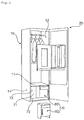
- the clothes treatment apparatus includes a cabinet 10 and a door 20 configured to open and close the front of the cabinet 10.
- the interior of the cabinet 10 is partitioned into upper and lower interior parts by a partition plate 11.
- a treatment chamber 12, in which clothes are hung, is defined in the interior of the cabinet 10 above the partition plate 11.
- a cycle chamber 14, in which machinery is installed, is defined in the interior of the cabinet 10 below the partition plate 11.
- Clothes are hung in the treatment chamber 12.
- wrinkles in the clothes are smoothed, or the clothes are deodorized, by the circulation of steam or air.
- a blowing unit 30 for circulating air in the treatment chamber 12, a steam unit 40 for supplying steam into the treatment chamber 12, a heat pump unit 50 for conditioning air in the treatment chamber 12, and a control unit 60 for controlling the respective units 30, 40, and 50 are installed in the cycle chamber 14.
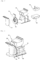
- an assembly of machinery including the blowing unit 30, the steam unit 40, the heat pump unit 50, and the control unit 60, which are required to perform respective cycles of the clothes treatment apparatus, is defined as a cycle assembly.
- the blowing unit 30 includes a blowing fan 32 and an inlet duct 34.
- the inlet duct 34 is installed at the suction side of the blowing fan 32 to guide air in the treatment chamber 12 to the blowing fan 32.
- the blowing fan 32 is rotated to blow air.
- the blowing fan 32 suctions air from the treatment chamber 12, and discharges the suctioned air to the heat pump unit 50.
- the steam unit 40 When the steam unit 40 is powered on, heat is generated from the steam unit 40.
- the steam unit 40 converts water supplied from a water supply tank 80, which will be described hereinafter, into steam.
- the generated steam is discharged into the treatment chamber 12.
- a flow channel is defined such that the steam flows into the treatment chamber 12 via the heat pump unit 50.
- the heat pump unit 50 constitutes a heat pump cycle including a compressor, a condenser, an evaporator, and an expansion valve. Based on the operation mode of the heat pump unit 50, cooled air or heated air may be discharged into the treatment chamber 12.
- the heat pump unit 50 may dehumidify air supplied from the blowing unit 30.
- a tank module 70 for storing water is installed in front of the cycle chamber 14.
- the tank module 70 includes a water supply tank 80 for supplying water to the steam unit 40 and a drainage tank 90 for gathering and storing condensed water that is generated in the treatment chamber 12.
- Water from the water supply tank 80 flows to the steam unit 40 via a water supply pump 45.
- Water that is condensed in the treatment chamber 12 flows to the lower side of the treatment chamber 12 due to gravity, and is then pumped to the drainage tank 90 by a drainage pump 46. Water that is condensed in the heat pump unit 50 also flows to the drainage tank 90 via the drainage pump 46.
- the water supply pump 45 or the drainage pump 46 is controlled by the control unit 60.
- a tank module frame 71 is installed in front of the inlet duct 34.
- a tank installation space 73 is defined between the tank module frame 71 and the door 20.
- the tank module frame 71 is coupled to the partition plate 11 to isolate the cycle chamber 14 from the outside.
- a tank support bar 75 which interferes with at least one selected from between the water supply tank 80 and the drainage tank 90, is installed in front of the tank installation space 73.
- the tank support bar 75 prevents the water supply tank 80 or the drainage tank 90 from being unintentionally separated from the tank installation space 73.
- the tank support bar 75 supports the front of the water supply tank 80 and the front of the drainage tank 90.
- the lower end of the water supply tank 80 is placed on the upper end of the tank support bar 75, and the lower end of the drainage tank 90 is placed on the upper end of the tank support bar 75.
- a tank support end 79, which interferes with the tank support bar 75, is formed on at least one selected from between the water supply tank 80 and the drainage tank 90.
- the tank support end 79 is concavely recessed.
- the front of the tank support bar 75 and the front of the water supply tank 80 may form a continuous surface due to the tank support end 79.
- the front of the tank support bar 75 and the front of the drainage tank 90 may form a continuous surface due to the tank support end 79
- the water supply tank 80 and the drainage tank 90 are disposed in the tank installation space 73 such that the water supply tank 80 and the drainage tank 90 are arranged parallel to each other in rightward and leftward directions.
- the water supply tank 80 and the drainage tank 90 are exposed to a user.
- the water supply tank 80 and the drainage tank 90 may be withdrawn by the user.
- the water supply tank 80 and the drainage tank 90 may be separated from the tank module frame 71.
- the water supply tank 80 and the drainage tank 90 may be separably mounted in the tank installation space 73.
- the water supply tank 80 is connected to the steam unit 40 to supply water to the steam unit 40.
- the drainage tank 90 is connected to the treatment chamber 12 to store water discharged from the treatment chamber 12 or the heat pump unit 50.
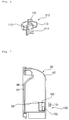
- the water supply tank 80 includes a tank body 82, which is open at the front thereof, a tank cover 84 coupled to the front of the tank body 82, a decorative cover 86 coupled to the tank cover 84, a water supply check valve 110 installed in the tank body 82 for opening and closing a flow channel connected with the steam unit 40, and a water supply level sensor 100 for sensing the level of water stored in the tank body 82.
- the front of the tank body 82 is open.
- the water supply level sensor 100 is disposed in the tank body 82.
- the upper end of the tank body 82 is round at the rear side thereof.
- the user may easily pull and withdraw the water tank 80, which is disposed at the lower side of the clothes treatment apparatus, due to the round shape of the tank body 82.
- the water supply level sensor 100 includes a float 102 installed in the tank body 82 such that the float 102 can move upward and downward based on the level of water stored in the tank body 82, a float cabinet 105 installed in the tank body 82 in a state in which the float 102 is disposed in the float cabinet 105, and a sensor 104 installed at the tank module frame 71 to sense the float 102.
- the float 102 has a magnet.
- the sensor 104 senses the magnetic force of the magnet.
- the sensor 104 may be installed at the front or rear of the tank module frame 71.
- the sensor 104 may be installed through the tank module frame 71.
- the sensor 104 may be located in any one selected from among the cycle chamber 14, the tank installation space 73, and the tank module frame 71.
- the float 102 which is installed in the water supply tank 80, is flush with the sensor 104.
- the float 102 moves lower than the sensor 104.
- the control unit 60 outputs a water deficiency signal. Even when the water deficiency signal is output, it is possible to supply a sufficient amount of steam during a cycle that is currently being performed.
- control unit 60 may determine whether the water supply tank 80 is mounted.
- control unit 60 when the water supply tank 80 is not mounted, or when water is deficient, the control unit 60 outputs a water deficiency signal.
- the control unit 60 When the user manipulates the clothes treatment apparatus in a state in which the water deficiency signal is output, therefore, the control unit 60 performs control such that the clothes treatment apparatus is not operated and outputs a water deficiency signal. At this time, the user may check the water supply tank 80.
- a float installation part 83, at which the float 102 is installed, is formed at the inside of the tank body 82.
- the float cabinet 105 is installed at the float installation part 83.
- the float 102 may move upward and downward along the float cabinet 105 by buoyancy.
- the float 102 is installed at the minimum level of water stored in the water supply tank 80, at which it is possible to supply an amount of steam corresponding to one cycle. Even when the sensor 104 fails to sense the float 102, and therefore the control unit 60 outputs a water deficiency signal, it is possible to supply an amount of steam corresponding to at least one cycle.
- the float cabinet 105 in which the float 102 is mounted, is manufactured by insert injection molding at the time of die slide injection (DSI) of the tank cover 84 and the tank body 82.
- DSI die slide injection
- DSI Die slide injection
- the tank body 82 and the tank cover 84 are manufactured by insert injection molding using DSI.
- the float cabinet 105 is installed in the tank body 82 and the tank cover 84 by insert injection molding.
- the edge of the tank cover 84 is integrally coupled to the edge of the tank body 82.
- the tank cover 84 has a window 85, through which the user may check the level of water in the tank body 82.
- a grip 87 into which the user may insert his/her hand in order to hold the tank cover 84, is concavely formed at the tank cover 84.
- the grip 87 is formed at the tank cover 84 such that the grip 87 is concave from the front to the rear thereof.
- a sensor fixing part 88 is formed at the inside of the tank cover 84.
- the sensor fixing part 88 protrudes from the inside of the tank cover 84. When the tank cover 84 and the tank body 82 are coupled to each other, the sensor fixing part 88 comes into tight contact with the float cabinet 105.
- the float cabinet 105 Since the sensor fixing part 88 tightly contacts the float cabinet 105, the float cabinet 105 is prevented from being separated from the float installation part 83.
- the sensor fixing part 88 may be integrally formed with the tank cover 84.
- the decorative cover 86 is formed to have a shape that is capable of covering the front of the tank cover 84. In addition, the decorative cover 86 is formed to have a shape corresponding to the shape of the tank cover 84.
- a water hole 81 is formed at the upper side of the tank body 82.
- a water hole cover 89 for opening and closing the water hole 81 is disposed at the upper side of the tank body 82.
- the water hole cover 89 is made of a flexible material exhibiting high elasticity. One end of the water hole cover 89 is fixed to the tank body 82, and the other end of the water hole cover 89 may be bent in order to open and close the water hole 82.
- the water supply check valve 110 includes a check valve hole 111 formed at the lower side of the tank body 82 and a check assembly 112 coupled to the check valve hole 111 for regulating the water in the tank body 82.
- the check assembly 112 includes a check housing 113 coupled into the check valve hole 111, the check housing 113 having a check flow channel 114, through which water flows into the check housing 113, a valve 115 disposed in the check housing 113 for opening and closing the check flow channel 114, and a check elastic member 116 disposed between the valve 115 and the tank body 82 for applying elastic force to the valve 115.
- valve 115 protrudes downward.
- the valve 115 may be pushed by the tank module frame 71, and may thus move upward.
- the check flow channel 114 is opened as the result of the movement of the valve 115.
- the check flow channel 114 is closed by the elastic force of the check elastic member 116.
- the drainage tank 90 is identical in function to the water supply tank 80.
- the drainage tank 90 is disposed alongside the water supply tank 80.
- a drainage check valve 120 is installed at the rear side thereof, not at the lower side thereof, unlike the water supply tank 80.
- the water supply tank 80 receives water through the water hole 81, and discharges water through the water supply check valve 110.
- the drainage tank 90 may receive condensed water through the drainage check valve 120, and may discharge condensed water through the water hole 81.
- the drainage check valve 120 of the drainage tank 90 may be disposed in a channel for receiving condensed water, not for discharging condensed water.
- condensed water may fall into the drainage tank 90 through the water hole 81.
- condensed water may be automatically discharged through the drainage check valve 120.
- Water that is condensed in the treatment chamber 12 and water that is condensed in the heat pump unit 50 are stored in the drainage tank 90.
- the float installation part 93 may be located at a height in the drainage tank 90 at which overflow does not occur even when an amount of condensed water that is generated during one cycle is stored therein.
- the float installation part 93 is located at a height in the drainage tank 90 at which overflow does not occur even when an amount of condensed water that is generated during one cycle is stored in the drainage tank 90.
- a drainage level sensor 101 of the drainage tank 90 senses a signal during the operation of the clothes treatment apparatus, therefore, the water in the drainage tank 90 does not overflow due to the condensed water that is additionally stored in the drainage tank 90.
- the drainage level sensor 101 of the drainage tank 90 is located higher than the water supply level sensor 100 in the water supply tank 80.
- the drainage level sensor 101 of the drainage tank 90 is identical in construction to the water supply level sensor 100 of the water supply tank 80. However, the drainage level sensor 101 of the drainage tank 90 is operated differently from the water supply level sensor 100 of the water supply tank 80.
- the senor 104 of the drainage tank 90 does not sense the float 102 in a normal state.
- the sensor 104 of the drainage tank 90 senses the float 102, which has been raised by buoyancy.
- the control unit 60 When the sensor 104 of the drainage tank 90 senses the float 102, the control unit 60 outputs a water drainage signal. When the water drainage signal is output, however, the overflow of condensed water does not occur during a cycle that is currently being performed.
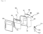
- a lower cabinet 130 on which the water supply tank 80 and the drainage tank 90 are mounted, is disposed at the lower side of the tank installation space 73.
- the lower cabinet 130 defines the tank installation space 73 together with the tank module frame 71.
- the lower cabinet 130 is an element that defines the lower part of the cabinet 10.
- the lower cabinet 130 is assembled with the tank module frame 71 to support the water supply tank 80 and the drainage tank 90.
- the lower cabinet 130 is an element that constitutes the cabinet 10.
- the lower cabinet 130 is provided with a flow channel, which connects the water supply tank 80 and the steam unit 40 to each other.
- the tank module frame 71 is provided with a flow channel, which connects the drainage tank 90 and the heat pump unit 50 to each other.
- the lower cabinet 130 includes a lower base 132, on which the water supply tank 80 and the drainage tank 90 are mounted, and a lower back 134 connected to the lower base 132, the lower back 134 being assembled with the tank module frame 71.
- a lower partition wall 136 is further provided to partition the lower base 132 into left and right base parts.
- One part of the lower base 132 partitioned by the lower partition wall 136 is defined as a first installation part 131, and the other part of the lower base 132 partitioned by the lower partition wall 136 is defined as a second installation part 133.
- the water supply tank 80 is mounted on the first installation part 131, and the drainage tank 90 is mounted on the second installation part 133.
- the lower partition wall 136 may not be provided.
- the lower back 134 forms a continuous surface with the tank module frame 71.
- the lower back 134 separates the cycle chamber 14 and the tank installation space 73 from each other together with the tank module frame 71.
- the lower back 134 is disposed perpendicular to the lower partition wall 136.
- the lower partition wall 136 partitions an installation space for the water supply tank 80 and an installation space for the drainage tank 90 from each other. In addition, the lower partition wall 136 prevents the water supply tank 80 or the drainage tank 90 from interfering with the drainage tank 90 or the water supply tank 80 when the water supply tank 80 or the drainage tank 90 is separated.
- the water supply tank 80 when the water supply tank 80 is shaken or lifted, a small amount of water from the water supply check valve 110 may be discharged into a receiving space 141.
- the water from the water supply check valve 110 When the water from the water supply check valve 110 is repeatedly discharged into the receiving space 141, the water may overflow the receiving space 141. As a result, the water may overflow a water pocket 140.
- the lower partition wall 136 functions to prevent interference between the water supply tank 80 and the drainage tank 90, which are adjacent to each other.
- the water pocket 140 is disposed on the first installation part 131.
- the water supply tank 80 is coupled to the water pocket 140.
- the water supply check valve 110 of the water supply tank 80 is inserted into the water pocket 140.
- a flow channel for connecting the water supply tank 80 and the steam unit 40 to each other is defined.
- the water pocket 140 stores a predetermined amount of water discharged from the water supply check valve 110.
- the water pocket 140 includes a pocket housing 142 formed at the lower base 132 such that the pocket housing 142 protrudes upward from the lower base 132, a water hole 145 formed at the pocket housing 142, the water hole 145 being provided with a flow channel communicating with the steam unit 40, and a water barrier 146 formed at the pocket housing 142, the water barrier 146 defining the receiving space 141 inside the pocket housing 142.
- the water hole 145 is formed inside the pocket housing 142.
- the pocket housing 142 is coupled with the water supply check valve 110 of the water supply tank 80.
- the pocket housing 142 supports the water supply tank 80.
- the water barrier 146 protrudes upward from the pocket housing 142.
- the pocket housing 142 may be recessed to define the receiving space 141.
- a small amount of water may be stored in the receiving space 141.
- the water hole 145 is located inside the receiving space 141.
- the water stored in the receiving space 141 may flow to the steam unit 40 via the water hole 145.
- the receiving space 141 is formed so as to be open toward the tank installation space 73.
- the water supply tank 80 may be mounted on the water barrier 146 such that the water supply tank 80 is supported by the water barrier 146.
- water discharged through the water supply check valve 110 may overflow the water pocket 140.
- the present invention provides a control method that is capable of moving water stored in the receiving space 141 to the steam unit 40. As a result, it is possible to prevent water in the receiving space 141 from overflowing the receiving space 141 when the water supply tank 80 is repeatedly separated.
- Water stored in the receiving space 141 is referred to as residual water.
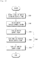
- a control method of the clothes treatment apparatus includes a step (S10) of sensing the level of water in the steam unit 40, a step (S20) of determining whether the level of water in the steam unit 40 is low, a step (S30) of, upon determining that the level of water in the steam unit 40 is low, sensing the level of water in the water supply tank 80, a step (S40) of, when the level of water in the water supply tank 80 is low, raising a water replenishment alarm, a step (S50) of operating the water supply pump 45 such that the water from the water supply tank 80 flows to the steam unit 40 to remove water stored in the receiving space 141, a step (S60) of maintaining the operation of the water supply pump 45 for a predetermined period of time, and a step (S70) of stopping the operation of the water supply pump 45 after the predetermined period of time.
- the low level means a reference level or less.
- the low level of the water in the water supply tank 80 means a state in which the sensor 140 cannot sense the float 120.
- the control method according to this embodiment is performed in order to prevent water stored in the receiving space 141 from overflowing the receiving space 141 during separation of the water supply tank 80.
- the user may separate the water supply tank 80 from the lower cabinet 130, and may replenish the water supply tank 80 with water. Subsequently, the user may couple the water supply tank 80, which has been replenished with water, to the lower cabinet 130.
- the control method according to this embodiment is performed in order to move water stored in the receiving space 141 to the steam unit 40 such that residual water stored in the receiving space 141 is prevented from overflowing from the receiving space 141.
- Steps S10 to S40 are performed in order to notify the user that it is necessary to replenish water.
- the level of water stored in the steam unit 40 is sensed and, it is determined whether the level of water stored in the steam unit 40 is low. Upon determining that the level of water stored in the steam unit 40 is low, the level of water in the water supply tank 80 is sensed at step S30.
- the water replenishment alarm may be raised through a display unit or a speaker unit of the clothes treatment apparatus.
- control unit 60 controls the water supply pump 45 to be operated such that the water from the water supply tank 80 flows to the steam unit 40.
- control unit 60 controls the water supply pump 45 to be operated such that all of the water stored in the water supply tank 80 moves to the steam unit 40. As all of the water stored in the water supply tank 80 moves to the steam unit 40, it is possible to remove all of the residual water from the receiving space 141.
- the residual water stored in the receiving space 141 moves to the steam unit 40, and is stored in the steam unit 40, by the operation of the water supply pump 45.
- the operation of the water supply pump 45 is continued for 10 seconds at step S60, and the operation of the water supply pump 45 is stopped at step S70.
- the above-defined period of time i.e. 10 seconds, is a period of time that is necessary to move all the water stored in the water supply tank 80 to the steam unit 40.
- the period of time may be set differently based on the size of the water supply tank 80.
- Steps S50 to S70 are defined as a residual water removal step (S880).
- the water supply pump 45 may be operated for a short period of time in order to remove only residual water stored in the receiving space 141.
- steps S50 to S70 may be performed in order to remove the residual water from the receiving space 141 without raising a water replenishment alarm.
- a second embodiment of the present invention will be described with reference to FIG. 15 .
- determination as to whether the level of water in the steam unit 40 is low is omitted, and, upon determining that the level of water in the water supply tank 80 is low, the water supply pump 45 is immediately operated in order to remove residual water from the receiving space 141, unlike the first embodiment.
- the steam unit 40 Since the water supply pump 45 is operated only when it is necessary to replenish the steam unit 40 with water, the steam unit 40 has a space that is capable of receiving water equivalent to the low level of water in the water supply tank 80.
- the water supply pump 45 is operated in order to move residual water from the receiving space 141 to the steam unit 40.
- the water supply pump 45 may be sufficiently operated for a predetermined period of time in order to move all of the water from the water supply tank 80 to the steam unit 40.
- the water supply pump 45 may be operated after a water replenishment alarm is raised. Alternatively, the water supply pump 45 may be operated irrespective of whether a water replenishment alarm is raised.
- control method of the clothes treatment apparatus according to the present invention has the following effects.
- the water supply tank installation space and the drainage tank installation space are partitioned by the lower partition wall. Consequently, it is possible to minimize the discharge of residual water.
Abstract
Description
- The present invention relates to a control method of a clothes treatment apparatus.
- Clothes treatment apparatuses are apparatuses that treat clothes, e.g. wash and dry clothes and smooth wrinkles in clothes, at home or at laundromats.
- Clothes treatment apparatuses may be classified into a washer for washing clothes, a dryer for drying clothes, a washer/dryer having both a washing function and a drying function, a refresher for refreshing clothes, and a steamer for removing unnecessary wrinkles in clothes.
- The refresher is an apparatus that keeps clothes comfortable and fresh. The refresher functions to dry clothes, to supply fragrance to clothes, to prevent the occurrence of static electricity in clothes, or to remove wrinkles from clothes.
- The steamer is an apparatus that simply supplies steam to clothes in order to remove wrinkles from the clothes. Unlike a general iron, the steamer removes wrinkles from the clothes without directly applying heat to the clothes.
- A clothes treatment apparatus having both functions of a refresher and a steamer may remove wrinkles from clothes received in the clothes treatment apparatus, and may additionally deodorize the clothes, using steam and hot air.
- An example of such a conventional treatment apparatus is disclosed in
Korean Patent Application Publication No. 10-2014-0016093 - Therefore, the present invention has been made in view of the above problems, and it is an object of the present invention to provide a control method of a clothes treatment apparatus that is capable of removing residual water that leaks from a water supply tank.
- This object is solved by the independent claim. The independent claims relate to further aspects of the invention.
- In accordance with an aspect of the present invention, the above and other objects can be accomplished by the provision of a control method of a clothes treatment apparatus including a cabinet partitioned into a treatment chamber for allowing clothes to be hung therein, a cycle chamber for allowing machinery to be installed therein, and a tank installation space for allowing a separable tank to be installed therein, a steam unit disposed in the cycle chamber for supplying steam into the treatment chamber, a water supply tank installed in the tank installation space, such that the water supply tank is connected to the steam unit, for supplying water to the steam unit, a water supply pump configured to be operated to supply the water in the water supply tank to the steam unit, a lower cabinet disposed in the tank installation space such that the water supply tank is separably coupled to the lower cabinet, and a receiving space formed at the lower cabinet, such that the receiving space is connected to the steam unit, for supplying water to the steam unit and storing residual water discharged during separation of the water supply tank, wherein the control method includes sensing the level of water in the water supply tank and, upon determining that the level of water in the water supply tank is low, operating the water supply pump to move the residual water stored in the receiving space to the steam unit.
- The control method may further include raising a water replenishment alarm, wherein the step of raising the water replenishment alarm may be performed between the step of sensing the level of water in the water supply tank and the step of operating the water supply pump to move the residual water stored in the receiving space to the steam unit or after the step of operating the water supply pump to move the residual water stored in the receiving space to the steam unit.
- The step of operating the water supply pump to move the residual water stored in the receiving space to the steam unit may include operating the water supply pump for a predetermined period of time and stopping the operation of the water supply pump after the predetermined period of time.
- The step of operating the water supply pump to move the residual water stored in the receiving space to the steam unit may include operating the water supply pump for a period of time that it takes to move all of the water in the water supply tank to the steam unit.
- The control method may further include sensing a level of water in the steam unit and determining whether the level of water in the steam unit is low, the step of sensing the level of water in the steam unit and the step of determining whether the level of water in the steam unit is low being performed before the step of sensing the level of water in the water supply tank, wherein the step of sensing the level of water in the water supply tank may be performed upon determining that the level of water in the steam unit is low.
- The receiving space may be formed so as to be open toward the tank installation space.
- The lower cabinet may further include a water pocket formed so as to protrude into the tank installation space, the receiving space may be formed inside the water pocket, and the water supply tank may be mounted on the water pocket such that the water supply tank is supported by the water pocket.
- The lower cabinet may further include a water barrier formed at the water pocket such that the water barrier protrudes upward from the water pocket, and the receiving space may be located inside the water barrier.
- The lower cabinet may include a lower base for allowing a drainage tank for storing condensed water and the water supply tank to be mounted thereon, a lower back connected to the lower base, the lower back being assembled with a tank module frame for partitioning the cycle chamber and the tank installation space from each other, and a lower partition wall for partitioning a first installation part for allowing the water supply tank to be installed thereon and a second installation part for allowing the drainage tank to be installed thereon from each other, and wherein the receiving space may be disposed on the first installation part.
- The control method may further include raising a water replenishment alarm, wherein the step of raising the water replenishment alarm may be performed between the step of sensing the level of water in the water supply tank and the step of operating the water supply pump to move the residual water stored in the receiving space to the steam unit or after the step of operating the water supply pump to move the residual water stored in the receiving space to the steam unit, and wherein the step of operating the water supply pump to move the residual water stored in the receiving space to the steam unit may include operating the water supply pump for a predetermined period of time and stopping the operation of the water supply pump after the predetermined period of time.
- The control method may further include raising a water replenishment alarm, wherein the step of raising the water replenishment alarm may be performed between the step of sensing the level of water in the water supply tank and the step of operating the water supply pump to move the residual water stored in the receiving space to the steam unit or after the step of operating the water supply pump to move the residual water stored in the receiving space to the steam unit, wherein the step of operating the water supply pump to move the residual water stored in the receiving space to the steam unit may include operating the water supply pump for a predetermined period of time and stopping the operation of the water supply pump after the predetermined period of time, and wherein the step of operating the water supply pump to move the residual water stored in the receiving space to the steam unit may include operating the water supply pump for a period of time that it takes to move all of the water in the water supply tank to the steam unit.
- The step of operating the water supply pump to move the residual water stored in the receiving space to the steam unit may include operating the water supply pump for a predetermined period of time and stopping the operation of the water supply pump after the predetermined period of time, and wherein the step of operating the water supply pump to move the residual water stored in the receiving space to the steam unit may include operating the water supply pump for a period of time that it takes to move all of the water in the water supply tank to the steam unit.
- The control method may further include sensing the level of water in the steam unit and determining whether the level of water in the steam unit is low, the step of sensing the level of water in the steam unit and the step of determining whether the level of water in the steam unit is low being performed before the step of sensing the level of water in the water supply tank, wherein the step of sensing the level of water in the water supply tank may be performed upon determining that the level of water in the steam unit is low, wherein the step of operating the water supply pump to move the residual water stored in the receiving space to the steam unit may include operating the water supply pump for a predetermined period of time and stopping the operation of the water supply pump after the predetermined period of time, and wherein the step of operating the water supply pump to move the residual water stored in the receiving space to the steam unit may include operating the water supply pump for a period of time that it takes to move all of the water in the water supply tank to the steam unit.
- The lower cabinet may further include a water pocket formed so as to protrude into the tank installation space, the receiving space may be formed inside the water pocket, and the water supply tank may be mounted on the water pocket such that the water supply tank is supported by the water pocket, wherein the lower cabinet may include a lower base for allowing a drainage tank for storing condensed water and the water supply tank to be mounted thereon, a lower back connected to the lower base, the lower back being assembled with a tank module frame for partitioning the cycle chamber and the tank installation space from each other, and a lower partition wall for partitioning a first installation part for allowing the water supply tank to be installed thereon and a second installation part for allowing the drainage tank to be installed thereon from each other, and wherein the receiving space is disposed on the first installation part.
- The embodiments will be described in detail with reference to the following drawings in which like reference numerals refer to like elements wherein:
-
FIG. 1 is a perspective view of a clothes treatment apparatus according to a first embodiment of the present invention; -
FIG. 2 is an exploded perspective view of a cycle assembly according to a first embodiment of the present invention; -
FIG. 3 is a perspective view of the cycle assembly according to the first embodiment of the present invention; -
FIG. 4 is an exploded perspective view of a water supply tank shown inFIG. 1 ; -
FIG. 5 is a partially exploded perspective view of the water supply tank shown inFIG. 1 ; -
FIG. 6 is a sectional perspective view of a check assembly shown inFIG. 5 ; -
FIG. 7 is a side sectional view of the water supply tank shown inFIG. 1 ; -
FIG. 8 is a perspective view of a drainage tank shown inFIG. 1 ; -
FIG. 9 is a partially exploded perspective view of the drainage tank shown inFIG. 1 ; -
FIG. 10 is a side sectional view of the drainage tank shown inFIG. 1 ; -
FIG. 11 is a perspective view of a lower cabinet shown inFIG. 1 ; -
FIG. 12 is a perspective view of the lower cabinet shown inFIG. 11 ; -
FIG. 13 is a block diagram of the clothes treatment apparatus shown inFIG. 1 ; -
FIG. 14 is a flowchart showing a control method of a clothes treatment apparatus according to a first embodiment of the present invention; and -
FIG. 15 is a flowchart showing a control method of a clothes treatment apparatus according to a second embodiment of the present invention. - The present invention will be described in detail with reference to the accompanying drawings.
- In the following description of the present invention, a detailed description of known functions or configurations incorporated herein will be omitted when it may make the subject matter of the present invention rather unclear. The same terms may be denoted by different reference numerals if the terms indicate different parts.
- The terms used in the following description are terms defined taking into consideration the functions obtained in accordance with the present invention. The definitions of these terms should be determined based on the whole content of this specification because they may be changed in accordance with the intentions of users, such as experimenters and measurers, or usual practices.
- In this specification, the terms "first," "second," etc. are used to describe various elements. However, the elements are not limited by the terms. The terms are used only to distinguish one element from another element. For example, a first element may be named a second element, and a second element may be named a first element, without departing from the scope of right of the present invention. It will be understood that the term "and/or" refers to one or more possible combinations of specified relevant items and includes such combinations.
- The terms used in this specification are provided only to explain specific embodiments, but are not intended to restrict the present invention. A singular representation may include a plural representation unless it represents a definitely different meaning from the context.
- Unless otherwise defined, all terms, including technical and scientific terms, used in this specification have the same meaning as commonly understood by a person having ordinary skill in the art to which the present invention pertains. It will be further understood that terms, such as those defined in commonly used dictionaries, should be interpreted as having a meaning that is consistent with their meaning in the context of the relevant art and the present disclosure, and will not be interpreted in an idealized or overly formal sense unless expressly so defined herein.
- In addition, the terms "comprises" and "includes" described herein should be interpreted not to exclude other elements but to further include such other elements since the corresponding elements may be inherent unless mentioned otherwise.
- Hereinafter, a clothes treatment apparatus according to a first embodiment of the present invention and a control method of a clothes treatment apparatus according to a first embodiment of the present invention will be described with reference to
FIGS. 1 to 14 . - The clothes treatment apparatus according to this embodiment includes a
cabinet 10 and adoor 20 configured to open and close the front of thecabinet 10. - The interior of the
cabinet 10 is partitioned into upper and lower interior parts by apartition plate 11. Atreatment chamber 12, in which clothes are hung, is defined in the interior of thecabinet 10 above thepartition plate 11. Acycle chamber 14, in which machinery is installed, is defined in the interior of thecabinet 10 below thepartition plate 11. - Clothes are hung in the
treatment chamber 12. In thetreatment chamber 12, wrinkles in the clothes are smoothed, or the clothes are deodorized, by the circulation of steam or air. - A blowing
unit 30 for circulating air in thetreatment chamber 12, asteam unit 40 for supplying steam into thetreatment chamber 12, aheat pump unit 50 for conditioning air in thetreatment chamber 12, and acontrol unit 60 for controlling therespective units cycle chamber 14. - In this embodiment, an assembly of machinery, including the
blowing unit 30, thesteam unit 40, theheat pump unit 50, and thecontrol unit 60, which are required to perform respective cycles of the clothes treatment apparatus, is defined as a cycle assembly. - The blowing
unit 30 includes a blowingfan 32 and aninlet duct 34. - The
inlet duct 34 is installed at the suction side of the blowingfan 32 to guide air in thetreatment chamber 12 to the blowingfan 32. - The blowing
fan 32 is rotated to blow air. The blowingfan 32 suctions air from thetreatment chamber 12, and discharges the suctioned air to theheat pump unit 50. - When the
steam unit 40 is powered on, heat is generated from thesteam unit 40. Thesteam unit 40 converts water supplied from awater supply tank 80, which will be described hereinafter, into steam. The generated steam is discharged into thetreatment chamber 12. - In this embodiment, a flow channel is defined such that the steam flows into the
treatment chamber 12 via theheat pump unit 50. - The
heat pump unit 50 constitutes a heat pump cycle including a compressor, a condenser, an evaporator, and an expansion valve. Based on the operation mode of theheat pump unit 50, cooled air or heated air may be discharged into thetreatment chamber 12. - In particular, the
heat pump unit 50 may dehumidify air supplied from the blowingunit 30. - A
tank module 70 for storing water is installed in front of thecycle chamber 14. Thetank module 70 includes awater supply tank 80 for supplying water to thesteam unit 40 and adrainage tank 90 for gathering and storing condensed water that is generated in thetreatment chamber 12. - Water from the
water supply tank 80 flows to thesteam unit 40 via awater supply pump 45. - Water that is condensed in the
treatment chamber 12, flows to the lower side of thetreatment chamber 12 due to gravity, and is then pumped to thedrainage tank 90 by adrainage pump 46. Water that is condensed in theheat pump unit 50 also flows to thedrainage tank 90 via thedrainage pump 46. - The
water supply pump 45 or thedrainage pump 46 is controlled by thecontrol unit 60. - In this embodiment, a
tank module frame 71 is installed in front of theinlet duct 34. - A
tank installation space 73 is defined between thetank module frame 71 and thedoor 20. Thetank module frame 71 is coupled to thepartition plate 11 to isolate thecycle chamber 14 from the outside. - A
tank support bar 75, which interferes with at least one selected from between thewater supply tank 80 and thedrainage tank 90, is installed in front of thetank installation space 73. - The
tank support bar 75 prevents thewater supply tank 80 or thedrainage tank 90 from being unintentionally separated from thetank installation space 73. Thetank support bar 75 supports the front of thewater supply tank 80 and the front of thedrainage tank 90. - When the
door 20 is opened and closed, therefore, thewater supply tank 80 and thedrainage tank 90 are prevented from being separated from thetank installation space 73. - In this embodiment, the lower end of the
water supply tank 80 is placed on the upper end of thetank support bar 75, and the lower end of thedrainage tank 90 is placed on the upper end of thetank support bar 75. - A
tank support end 79, which interferes with thetank support bar 75, is formed on at least one selected from between thewater supply tank 80 and thedrainage tank 90. - The
tank support end 79 is concavely recessed. - The front of the
tank support bar 75 and the front of thewater supply tank 80 may form a continuous surface due to thetank support end 79. In addition, the front of thetank support bar 75 and the front of thedrainage tank 90 may form a continuous surface due to thetank support end 79 - The
water supply tank 80 and thedrainage tank 90 are disposed in thetank installation space 73 such that thewater supply tank 80 and thedrainage tank 90 are arranged parallel to each other in rightward and leftward directions. - When the
door 20 is opened, thewater supply tank 80 and thedrainage tank 90 are exposed to a user. - The
water supply tank 80 and thedrainage tank 90 may be withdrawn by the user. - The
water supply tank 80 and thedrainage tank 90 may be separated from thetank module frame 71. Thewater supply tank 80 and thedrainage tank 90 may be separably mounted in thetank installation space 73. - The
water supply tank 80 is connected to thesteam unit 40 to supply water to thesteam unit 40. Thedrainage tank 90 is connected to thetreatment chamber 12 to store water discharged from thetreatment chamber 12 or theheat pump unit 50. - The
water supply tank 80 includes atank body 82, which is open at the front thereof, atank cover 84 coupled to the front of thetank body 82, adecorative cover 86 coupled to thetank cover 84, a watersupply check valve 110 installed in thetank body 82 for opening and closing a flow channel connected with thesteam unit 40, and a watersupply level sensor 100 for sensing the level of water stored in thetank body 82. - The front of the
tank body 82 is open. The watersupply level sensor 100 is disposed in thetank body 82. - The upper end of the
tank body 82 is round at the rear side thereof. - When the
tank body 82 is separated, interference between thetank body 82 and thepartition plate 11 is minimized. - The user may easily pull and withdraw the
water tank 80, which is disposed at the lower side of the clothes treatment apparatus, due to the round shape of thetank body 82. - In this embodiment, the water
supply level sensor 100 includes afloat 102 installed in thetank body 82 such that thefloat 102 can move upward and downward based on the level of water stored in thetank body 82, afloat cabinet 105 installed in thetank body 82 in a state in which thefloat 102 is disposed in thefloat cabinet 105, and asensor 104 installed at thetank module frame 71 to sense thefloat 102. - The
float 102 has a magnet. Thesensor 104 senses the magnetic force of the magnet. - The
sensor 104 may be installed at the front or rear of thetank module frame 71. - The
sensor 104 may be installed through thetank module frame 71. - Consequently, the
sensor 104 may be located in any one selected from among thecycle chamber 14, thetank installation space 73, and thetank module frame 71. - The
float 102, which is installed in thewater supply tank 80, is flush with thesensor 104. When the level of water stored in thewater supply tank 80 is lowered, thefloat 102 moves lower than thesensor 104. When thesensor 104 fails to sense thefloat 102, therefore, thecontrol unit 60 outputs a water deficiency signal. Even when the water deficiency signal is output, it is possible to supply a sufficient amount of steam during a cycle that is currently being performed. - Since the
sensor 104 constantly senses thefloat 102, thecontrol unit 60 may determine whether thewater supply tank 80 is mounted. - For example, when the
water supply tank 80 is not mounted, or when water is deficient, thecontrol unit 60 outputs a water deficiency signal. - When the user manipulates the clothes treatment apparatus in a state in which the water deficiency signal is output, therefore, the
control unit 60 performs control such that the clothes treatment apparatus is not operated and outputs a water deficiency signal. At this time, the user may check thewater supply tank 80. - A
float installation part 83, at which thefloat 102 is installed, is formed at the inside of thetank body 82. Thefloat cabinet 105 is installed at thefloat installation part 83. Thefloat 102 may move upward and downward along thefloat cabinet 105 by buoyancy. - In this embodiment, the
float 102 is installed at the minimum level of water stored in thewater supply tank 80, at which it is possible to supply an amount of steam corresponding to one cycle. Even when thesensor 104 fails to sense thefloat 102, and therefore thecontrol unit 60 outputs a water deficiency signal, it is possible to supply an amount of steam corresponding to at least one cycle. - That is, even when a water deficiency signal is sensed during the supply of steam, it is possible to supply a sufficient amount of steam until a cycle that is currently being performed is completed.
- The
float cabinet 105, in which thefloat 102 is mounted, is manufactured by insert injection molding at the time of die slide injection (DSI) of thetank cover 84 and thetank body 82. - Die slide injection (DSI) is a molding technology that has been developed for blow molding or molding of thin products. DSI conveys various advantages in that no post-processing, such as adhesion or assembly, is necessary after injection molding, it is possible to adjust the thickness of a wall more easily than when blow molding or gas molding, it is possible to provide an excellent surface shape or high dimensional accuracy, and it is possible to perform DSI more easily than double injection or blow molding. The manufacturing of products using DSI is ordinarily known in the art to which the present invention pertains, and therefore a detailed description thereof will be omitted.
- The
tank body 82 and thetank cover 84 are manufactured by insert injection molding using DSI. During the manufacturing of thetank body 82 and thetank cover 84, thefloat cabinet 105 is installed in thetank body 82 and thetank cover 84 by insert injection molding. During the manufacturing of thetank body 82 and thetank cover 84, the edge of thetank cover 84 is integrally coupled to the edge of thetank body 82. - The tank cover 84 has a
window 85, through which the user may check the level of water in thetank body 82. In addition, agrip 87, into which the user may insert his/her hand in order to hold thetank cover 84, is concavely formed at thetank cover 84. - The
grip 87 is formed at thetank cover 84 such that thegrip 87 is concave from the front to the rear thereof. - A
sensor fixing part 88 is formed at the inside of thetank cover 84. Thesensor fixing part 88 protrudes from the inside of thetank cover 84. When thetank cover 84 and thetank body 82 are coupled to each other, thesensor fixing part 88 comes into tight contact with thefloat cabinet 105. - Since the
sensor fixing part 88 tightly contacts thefloat cabinet 105, thefloat cabinet 105 is prevented from being separated from thefloat installation part 83. - The
sensor fixing part 88 may be integrally formed with thetank cover 84. - The
decorative cover 86 is formed to have a shape that is capable of covering the front of thetank cover 84. In addition, thedecorative cover 86 is formed to have a shape corresponding to the shape of thetank cover 84. - A
water hole 81 is formed at the upper side of thetank body 82. In addition, awater hole cover 89 for opening and closing thewater hole 81 is disposed at the upper side of thetank body 82. - The
water hole cover 89 is made of a flexible material exhibiting high elasticity. One end of thewater hole cover 89 is fixed to thetank body 82, and the other end of thewater hole cover 89 may be bent in order to open and close thewater hole 82. - The water
supply check valve 110 includes acheck valve hole 111 formed at the lower side of thetank body 82 and acheck assembly 112 coupled to thecheck valve hole 111 for regulating the water in thetank body 82. - The
check assembly 112 includes acheck housing 113 coupled into thecheck valve hole 111, thecheck housing 113 having acheck flow channel 114, through which water flows into thecheck housing 113, avalve 115 disposed in thecheck housing 113 for opening and closing thecheck flow channel 114, and a checkelastic member 116 disposed between thevalve 115 and thetank body 82 for applying elastic force to thevalve 115. - The small-diameter side of the
valve 115 protrudes downward. When thevalve 115 is placed on thetank module frame 71, thevalve 115 may be pushed by thetank module frame 71, and may thus move upward. At this time, thecheck flow channel 114 is opened as the result of the movement of thevalve 115. When thewater supply tank 80 is separated from thetank module frame 71, thecheck flow channel 114 is closed by the elastic force of the checkelastic member 116. - The
drainage tank 90 is identical in function to thewater supply tank 80. Thedrainage tank 90 is disposed alongside thewater supply tank 80. - In the
drainage tank 90, adrainage check valve 120 is installed at the rear side thereof, not at the lower side thereof, unlike thewater supply tank 80. - The
water supply tank 80 receives water through thewater hole 81, and discharges water through the watersupply check valve 110. Thedrainage tank 90 may receive condensed water through thedrainage check valve 120, and may discharge condensed water through thewater hole 81. - That is, the
drainage check valve 120 of thedrainage tank 90 may be disposed in a channel for receiving condensed water, not for discharging condensed water. - Unlike this embodiment, condensed water may fall into the
drainage tank 90 through thewater hole 81. In addition, condensed water may be automatically discharged through thedrainage check valve 120. - Water that is condensed in the
treatment chamber 12 and water that is condensed in theheat pump unit 50 are stored in thedrainage tank 90. - A
float installation part 93, at which thefloat cabinet 105 is installed, is formed in thedrainage tank 90. - The
float installation part 93 may be located at a height in thedrainage tank 90 at which overflow does not occur even when an amount of condensed water that is generated during one cycle is stored therein. - That is, the
float installation part 93 is located at a height in thedrainage tank 90 at which overflow does not occur even when an amount of condensed water that is generated during one cycle is stored in thedrainage tank 90. - When a
drainage level sensor 101 of thedrainage tank 90 senses a signal during the operation of the clothes treatment apparatus, therefore, the water in thedrainage tank 90 does not overflow due to the condensed water that is additionally stored in thedrainage tank 90. - The
drainage level sensor 101 of thedrainage tank 90 is located higher than the watersupply level sensor 100 in thewater supply tank 80. - The
drainage level sensor 101 of thedrainage tank 90 is identical in construction to the watersupply level sensor 100 of thewater supply tank 80. However, thedrainage level sensor 101 of thedrainage tank 90 is operated differently from the watersupply level sensor 100 of thewater supply tank 80. - For example, the
sensor 104 of thedrainage tank 90 does not sense thefloat 102 in a normal state. When the level of condensed water rises, thesensor 104 of thedrainage tank 90 senses thefloat 102, which has been raised by buoyancy. - When the
sensor 104 of thedrainage tank 90 senses thefloat 102, thecontrol unit 60 outputs a water drainage signal. When the water drainage signal is output, however, the overflow of condensed water does not occur during a cycle that is currently being performed. - Meanwhile, a
lower cabinet 130, on which thewater supply tank 80 and thedrainage tank 90 are mounted, is disposed at the lower side of thetank installation space 73. Thelower cabinet 130 defines thetank installation space 73 together with thetank module frame 71. - The
lower cabinet 130 is an element that defines the lower part of thecabinet 10. Thelower cabinet 130 is assembled with thetank module frame 71 to support thewater supply tank 80 and thedrainage tank 90. - Hereinafter, the
lower cabinet 130 will be described in detail with reference toFIGS. 11 and12 . - The
lower cabinet 130 is an element that constitutes thecabinet 10. - In this embodiment, the
lower cabinet 130 is provided with a flow channel, which connects thewater supply tank 80 and thesteam unit 40 to each other. In this embodiment, thetank module frame 71 is provided with a flow channel, which connects thedrainage tank 90 and theheat pump unit 50 to each other. - The
lower cabinet 130 includes alower base 132, on which thewater supply tank 80 and thedrainage tank 90 are mounted, and a lower back 134 connected to thelower base 132, the lower back 134 being assembled with thetank module frame 71. - In this embodiment, a
lower partition wall 136 is further provided to partition thelower base 132 into left and right base parts. One part of thelower base 132 partitioned by thelower partition wall 136 is defined as afirst installation part 131, and the other part of thelower base 132 partitioned by thelower partition wall 136 is defined as asecond installation part 133. - In this embodiment, the
water supply tank 80 is mounted on thefirst installation part 131, and thedrainage tank 90 is mounted on thesecond installation part 133. Unlike this embodiment, thelower partition wall 136 may not be provided. - The lower back 134 forms a continuous surface with the
tank module frame 71. - The
lower back 134 separates thecycle chamber 14 and thetank installation space 73 from each other together with thetank module frame 71. - The
lower back 134 is disposed perpendicular to thelower partition wall 136. - The
lower partition wall 136 partitions an installation space for thewater supply tank 80 and an installation space for thedrainage tank 90 from each other. In addition, thelower partition wall 136 prevents thewater supply tank 80 or thedrainage tank 90 from interfering with thedrainage tank 90 or thewater supply tank 80 when thewater supply tank 80 or thedrainage tank 90 is separated. - As will be described hereinafter, when the
water supply tank 80 is shaken or lifted, a small amount of water from the watersupply check valve 110 may be discharged into a receivingspace 141. When the water from the watersupply check valve 110 is repeatedly discharged into the receivingspace 141, the water may overflow the receivingspace 141. As a result, the water may overflow awater pocket 140. Thelower partition wall 136 functions to prevent interference between thewater supply tank 80 and thedrainage tank 90, which are adjacent to each other. - In this embodiment, the
water pocket 140 is disposed on thefirst installation part 131. - The
water supply tank 80 is coupled to thewater pocket 140. - The water
supply check valve 110 of thewater supply tank 80 is inserted into thewater pocket 140. - When the water
supply check valve 110 is inserted into thewater pocket 140, a flow channel for connecting thewater supply tank 80 and thesteam unit 40 to each other is defined. - The
water pocket 140 stores a predetermined amount of water discharged from the watersupply check valve 110. - The
water pocket 140 includes apocket housing 142 formed at thelower base 132 such that thepocket housing 142 protrudes upward from thelower base 132, awater hole 145 formed at thepocket housing 142, thewater hole 145 being provided with a flow channel communicating with thesteam unit 40, and awater barrier 146 formed at thepocket housing 142, thewater barrier 146 defining the receivingspace 141 inside thepocket housing 142. - The
water hole 145 is formed inside thepocket housing 142. Thepocket housing 142 is coupled with the watersupply check valve 110 of thewater supply tank 80. Thepocket housing 142 supports thewater supply tank 80. - In this embodiment, the
water barrier 146 protrudes upward from thepocket housing 142. Unlike this embodiment, thepocket housing 142 may be recessed to define the receivingspace 141. - A small amount of water may be stored in the receiving
space 141. Thewater hole 145 is located inside the receivingspace 141. The water stored in the receivingspace 141 may flow to thesteam unit 40 via thewater hole 145. - The receiving
space 141 is formed so as to be open toward thetank installation space 73. - The
water supply tank 80 may be mounted on thewater barrier 146 such that thewater supply tank 80 is supported by thewater barrier 146. - When the
water supply tank 80 is mounted on thewater pocket 140, the watersupply check valve 110 remains open. - As a result, when the
water supply tank 80 is separated from thelower cabinet 130, a small amount of water may be discharged through the watersupply check valve 110. The discharged water is stored in the receivingspace 141. That is, when thewater supply tank 80 is separated, a small amount of water discharged while the watersupply check valve 110 is closed may be stored in the receivingspace 141. - When the
water supply tank 80 is repeatedly separated, water discharged through the watersupply check valve 110 may overflow thewater pocket 140. - In this embodiment, the present invention provides a control method that is capable of moving water stored in the receiving
space 141 to thesteam unit 40. As a result, it is possible to prevent water in the receivingspace 141 from overflowing the receivingspace 141 when thewater supply tank 80 is repeatedly separated. - Water stored in the receiving
space 141 is referred to as residual water. - A control method of the clothes treatment apparatus according to this embodiment includes a step (S10) of sensing the level of water in the
steam unit 40, a step (S20) of determining whether the level of water in thesteam unit 40 is low, a step (S30) of, upon determining that the level of water in thesteam unit 40 is low, sensing the level of water in thewater supply tank 80, a step (S40) of, when the level of water in thewater supply tank 80 is low, raising a water replenishment alarm, a step (S50) of operating thewater supply pump 45 such that the water from thewater supply tank 80 flows to thesteam unit 40 to remove water stored in the receivingspace 141, a step (S60) of maintaining the operation of thewater supply pump 45 for a predetermined period of time, and a step (S70) of stopping the operation of thewater supply pump 45 after the predetermined period of time. - The low level means a reference level or less.
- In this embodiment, the low level of the water in the
water supply tank 80 means a state in which thesensor 140 cannot sense thefloat 120. - The control method according to this embodiment is performed in order to prevent water stored in the receiving
space 141 from overflowing the receivingspace 141 during separation of thewater supply tank 80. - In a case in which insufficient water is stored in the
water supply tank 80, the user may separate thewater supply tank 80 from thelower cabinet 130, and may replenish thewater supply tank 80 with water. Subsequently, the user may couple thewater supply tank 80, which has been replenished with water, to thelower cabinet 130. - At this time, if residual water is stored in the receiving
space 141, the water overflows the receivingspace 141 when thewater supply tank 80 is coupled to thelower cabinet 130. - The control method according to this embodiment is performed in order to move water stored in the receiving
space 141 to thesteam unit 40 such that residual water stored in the receivingspace 141 is prevented from overflowing from the receivingspace 141. - Steps S10 to S40 are performed in order to notify the user that it is necessary to replenish water.
- At steps S10 and S20, the level of water stored in the
steam unit 40 is sensed and, it is determined whether the level of water stored in thesteam unit 40 is low. Upon determining that the level of water stored in thesteam unit 40 is low, the level of water in thewater supply tank 80 is sensed at step S30. - When the level of water stored in the
water supply tank 80 sensed at step S30 is low, a water replenishment alarm is raised in order to notify the user that it is necessary to replenish water. - The water replenishment alarm may be raised through a display unit or a speaker unit of the clothes treatment apparatus.
- Upon determining at step S30 that the level of water stored in the
water supply tank 80 is low, thecontrol unit 60 controls thewater supply pump 45 to be operated such that the water from thewater supply tank 80 flows to thesteam unit 40. - In this embodiment, the
control unit 60 controls thewater supply pump 45 to be operated such that all of the water stored in thewater supply tank 80 moves to thesteam unit 40. As all of the water stored in thewater supply tank 80 moves to thesteam unit 40, it is possible to remove all of the residual water from the receivingspace 141. - The residual water stored in the receiving
space 141 moves to thesteam unit 40, and is stored in thesteam unit 40, by the operation of thewater supply pump 45. - As the residual water is removed from the receiving
space 141, it is possible to prevent the residual water from overflowing the receivingspace 141 even though a small amount of water is discharged when the user separates thewater supply tank 80 from thelower cabinet 130 to replenish water. - In this embodiment, after the
water supply pump 45 is operated, the operation of thewater supply pump 45 is continued for 10 seconds at step S60, and the operation of thewater supply pump 45 is stopped at step S70. - The above-defined period of time, i.e. 10 seconds, is a period of time that is necessary to move all the water stored in the
water supply tank 80 to thesteam unit 40. The period of time may be set differently based on the size of thewater supply tank 80. - In a case in which all of the water is removed from the
water supply tank 80, as described above, it is possible to store a larger amount of water in thewater supply tank 80 when the user replenishes thewater supply tank 80 with water. - In other words, in a case in which all of the water is removed from the receiving
space 141 and thewater supply tank 80 during a residual water removal process, and then the user replenishes thewater supply tank 80 with water, it is possible to maximize the amount of water that is stored in the clothes treatment apparatus. As a result, it is possible to reduce the frequency with which the user replenishes thewater supply tank 80 with water. - Steps S50 to S70 are defined as a residual water removal step (S880).
- Meanwhile, unlike this embodiment, the
water supply pump 45 may be operated for a short period of time in order to remove only residual water stored in the receivingspace 141. - In addition, unlike this embodiment, when the low level of the water in the
water supply tank 80 is sensed, steps S50 to S70 may be performed in order to remove the residual water from the receivingspace 141 without raising a water replenishment alarm. - A second embodiment of the present invention will be described with reference to
FIG. 15 . - In the second embodiment of the present invention, determination as to whether the level of water in the
steam unit 40 is low is omitted, and, upon determining that the level of water in thewater supply tank 80 is low, thewater supply pump 45 is immediately operated in order to remove residual water from the receivingspace 141, unlike the first embodiment. - Since the
water supply pump 45 is operated only when it is necessary to replenish thesteam unit 40 with water, thesteam unit 40 has a space that is capable of receiving water equivalent to the low level of water in thewater supply tank 80. - In this embodiment, therefore, upon determining that the level of water in the
water supply tank 80 is low, thewater supply pump 45 is operated in order to move residual water from the receivingspace 141 to thesteam unit 40. - The
water supply pump 45 may be sufficiently operated for a predetermined period of time in order to move all of the water from thewater supply tank 80 to thesteam unit 40. - In addition, the
water supply pump 45 may be operated after a water replenishment alarm is raised. Alternatively, thewater supply pump 45 may be operated irrespective of whether a water replenishment alarm is raised. - For example, unlike this embodiment, upon determining that the level of water in the
water supply tank 80 is low, all of the residual water or the water remaining in thewater supply tank 80 may be moved to thesteam unit 40, and then a water replenishment alarm may be raised. - As a result, it is possible to prevent the user from separating the water supply tank during the movement of the water from the
water supply tank 80 to thesteam unit 40. - Other configurations of the second embodiment are identical to those of the first embodiment, and therefore a detailed description thereof will be omitted.
- As is apparent from the above description, the control method of the clothes treatment apparatus according to the present invention has the following effects.
- First, residual water discharged and stored in the receiving space during separation of the water supply tank is moved to the steam unit. Consequently, it is possible to prevent the residual water from overflowing the receiving space when the water supply tank is mounted.
- Second, when it is determined that the level of water in the water supply tank is low, all of the residual water stored in the receiving space and all of the water remaining in the water supply tank are moved to the steam unit. Consequently, it is possible to securely remove the residual water from the receiving space.
- Third, when it is determined that the level of water in the water supply tank is low, all of the residual water stored in the receiving space and all of the water remaining in the water supply tank are moved to the steam unit. Consequently, it is possible to maximize the amount of water stored in the clothes treatment apparatus when the user replenishes the water supply tank with water.
- Fourth, when residual water is removed from the receiving space, the maximum amount of water that is usable is stored in the steam unit. Consequently, it is possible to reduce the number of times that water is replenished.
- Fifth, the water supply tank installation space and the drainage tank installation space are partitioned by the lower partition wall. Consequently, it is possible to minimize the discharge of residual water.
- It will be apparent that, although the embodiments of the present invention have been described above with reference to the accompanying drawings, the present invention is not limited to the above-described specific embodiments, and therefore various modifications and variations can be made by those skilled in the art without departing from the gist of the appended claims. Thus, it is intended that the modifications and variations should not be understood independently of the technical spirit or prospect of the present invention. The above embodiments are therefore to be construed in all aspects as illustrative and not restrictive.
Claims (14)
- A control method of a clothes treatment apparatus comprising:a cabinet (10) partitioned into a treatment chamber (12) for allowing clothes to be hung therein, a cycle chamber (14) for allowing machinery to be installed therein, and a tank installation space (73) for allowing a separable tank to be installed therein;a steam unit (40) disposed in the cycle chamber (14) for supplying steam into the treatment chamber (12);a water supply tank (80) installed in the tank installation space, such that the water supply tank (80) is connected to the steam unit (40), for supplying water to the steam unit;a water supply pump (45) configured to be operated to supply the water from the water supply tank (80) to the steam unit (40);a lower cabinet (130) disposed in the tank installation space (73) such that the water supply tank (80) is separably coupled to the lower cabinet (73); anda receiving space (141) formed at the lower cabinet (130), such that the receiving space (141) is connected to the steam unit (40), for supplying water to the steam unit (40) and storing residual water discharged during separation of the water supply tank (80), whereinthe control method comprises:sensing a level of water in the water supply tank (80); andupon determining that the level of water in the water supply tank (80) is low, operating the water supply pump (45) to move the residual water stored in the receiving space (141) to the steam unit(40).
- The control method according to claim 1, further comprising raising a water replenishment alarm, wherein the step of raising the water replenishment alarm is performed between the step of sensing the level of water in the water supply tank (80) and the step of operating the water supply pump to move the residual water stored in the receiving space (141) to the steam unit (40) or after the step of operating the water supply pump (45) to move the residual water stored in the receiving space (141) to the steam unit (40).
- The control method according to claims 1 or 2, wherein the step of operating the water supply pump (45) to move the residual water stored in the receiving space (141) to the steam unit (40) comprises operating the water supply pump (45) for a predetermined period of time and stopping operation of the water supply pump (45) after the predetermined period of time.
- The control method according to any one of claims 1 to 3, wherein the step of operating the water supply pump (45) to move the residual water stored in the receiving space (141) to the steam unit (40) comprises operating the water supply pump (45) for a period of time necessary to move all of the water in the water supply tank (80) to the steam unit (40).
- The control method according to any one of claims 1 to 4, further comprising:sensing a level of water in the steam unit (40); anddetermining whether the level of water in the steam unit (40) is low,the step of sensing the level of water in the steam unit (40) and the step of determining whether the level of water in the steam unit (40) is low being performed before the step of sensing the level of water in the water supply tank (80), whereinthe step of sensing the level of water in the water supply tank (80) is performed upon determining that the level of water in the steam unit (40) is low.
- The control method according to any one of claims 1 to 5, wherein the receiving space (141) is formed so as to be open toward the tank installation space (73).
- The control method according to any one of claims 1 to 6, wherein the lower cabinet (130) further comprises a water pocket (140) formed so as to protrude into the tank installation space (73), the receiving space (141) is formed inside the water pocket (140), and the water supply tank (80) is mounted on the water pocket (140) such that the water supply tank (80) is supported by the water pocket (140).
- The control method according to claim 7, wherein the lower cabinet (130) further comprises a water barrier (146) formed at the water pocket (140) such that the water barrier (146) protrudes upward from the water pocket (140), and the receiving space (141) is located inside the water barrier (146).
- The control method according to any one of claims 1 to 8, wherein the lower cabinet (130) comprises:a lower base (132) for allowing a drainage tank (90) for storing condensed water and the water supply tank (80) to be mounted thereon;a lower back (134) connected to the lower base (132), the lower back (134) being assembled with a tank module frame (71) for partitioning the cycle chamber (14) and the tank installation space (73) from each other; anda lower partition wall (136) for partitioning a first installation part (131) for allowing the water supply tank (80) to be installed thereon and a second installation part (133) for allowing the drainage tank (90) to be installed thereon from each other, and whereinthe receiving space (141) is disposed on the first installation part.
- The control method according to any one of claims 1 to 9, further comprising raising a water replenishment alarm, wherein the step of raising the water replenishment alarm is performed between the step of sensing the level of water in the water supply tank (80) and the step of operating the water supply pump (45) to move the residual water stored in the receiving space to the steam unit (40) or after the step of operating the water supply pump (45) to move the residual water stored in the receiving space (141) to the steam unit (40), and wherein
the step of operating the water supply pump (45) to move the residual water stored in the receiving space (141) to the steam unit (40) comprises operating the water supply pump (45) for a predetermined period of time and stopping operation of the water supply pump (45) after the predetermined period of time. - The control method according to any one of claims 1 to 9, further comprising raising a water replenishment alarm, wherein the step of raising the water replenishment alarm is performed between the step of sensing the level of water in the water supply tank (80) and the step of operating the water supply pump (45) to move the residual water stored in the receiving space (141) to the steam unit (40) or after the step of operating the water supply pump (45) to move the residual water stored in the receiving space (141) to the steam unit (40), wherein
the step of operating the water supply pump (45) to move the residual water stored in the receiving space (141) to the steam unit (40) comprises operating the water supply pump (45) for a predetermined period of time and stopping operation of the water supply pump (45) after the predetermined period of time, and wherein
the step of operating the water supply pump (45) to move the residual water stored in the receiving space (141) to the steam unit (40) comprises operating the water supply pump (45) for a period of time taken to move all of the water in the water supply tank (80) to the steam unit (40). - The control method according to any one of claims 1 to 9, wherein
the step of operating the water supply pump (45) to move the residual water stored in the receiving space (141) to the steam unit (40) comprises operating the water supply pump (45) for a predetermined period of time and stopping operation of the water supply pump (45) after the predetermined period of time, and wherein
the step of operating the water supply pump (45) to move the residual water stored in the receiving space (141) to the steam unit (40) comprises operating the water supply pump (45) for a period of time taken to move all of the water in the water supply tank to the steam unit. - The control method according to any one of claims 1 to 12, further comprising:sensing a level of water in the steam unit (40); anddetermining whether the level of water in the steam unit (40) is low,the step of sensing the level of water in the steam unit (40) and the step of determining whether the level of water in the steam unit (40) is low being performed before the step of sensing the level of water in the water supply tank (80), whereinthe step of sensing the level of water in the water supply tank (80) is performed upon determining that the level of water in the steam unit (40) is low, whereinthe step of operating the water supply pump (45) to move the residual water stored in the receiving space (141) to the steam unit (40) comprises operating the water supply pump (45) for a predetermined period of time and stopping operation of the water supply pump (45) after the predetermined period of time, and whereinthe step of operating the water supply pump (45) to move the residual water stored in the receiving space (141) to the steam unit (40) comprises operating the water supply pump for a period of time taken to move all of the water in the water supply tank (80) to the steam unit (40).
- The control method according to any one of claims 1 to 13, wherein
the lower cabinet (130) further comprises a water pocket (140) formed so as to protrude into the tank installation space (73), the receiving space (141) is formed inside the water pocket (140), and the water supply tank (80) is mounted on the water pocket (140) such that the water supply tank (80) is supported by the water pocket (140), wherein
the lower cabinet (130) comprises:a lower base (132) for allowing a drainage tank (90) for storing condensed water and the water supply tank (80) to be mounted thereon;a lower back (134) connected to the lower base (132), the lower back (134) being assembled with a tank module frame (71) for partitioning the cycle chamber (14) and the tank installation space (73) from each other; anda lower partition wall (136) for partitioning a first installation part (131) for allowing the water supply tank (80) to be installed thereon and a second installation part (133) for allowing the drainage tank (90) to be installed thereon from each other, and whereinthe receiving space (141) is disposed on the first installation part (131).
Applications Claiming Priority (1)
| Application Number | Priority Date | Filing Date | Title |
|---|---|---|---|
| KR1020140184453A KR101597104B1 (en) | 2014-12-19 | 2014-12-19 | Method for controlling process treatment clothes apparatus |
Publications (2)
| Publication Number | Publication Date |
|---|---|
| EP3034681A1 true EP3034681A1 (en) | 2016-06-22 |
| EP3034681B1 EP3034681B1 (en) | 2017-07-26 |
Family
ID=54850447
Family Applications (1)
| Application Number | Title | Priority Date | Filing Date |
|---|---|---|---|
| EP15201310.8A Active EP3034681B1 (en) | 2014-12-19 | 2015-12-18 | Control method of clothes treatment apparatus |
Country Status (6)
| Country | Link |
|---|---|
| US (1) | US9873971B2 (en) |
| EP (1) | EP3034681B1 (en) |
| JP (3) | JP7001473B2 (en) |
| KR (1) | KR101597104B1 (en) |
| CN (1) | CN105714537B (en) |
| WO (1) | WO2016099216A1 (en) |
Families Citing this family (7)
| Publication number | Priority date | Publication date | Assignee | Title |
|---|---|---|---|---|
| KR101597104B1 (en) * | 2014-12-19 | 2016-02-24 | 엘지전자 주식회사 | Method for controlling process treatment clothes apparatus |
| CN107881746B (en) * | 2017-12-22 | 2024-01-09 | 宁波爱佳电器有限公司 | Ventilating structure of electric iron |
| CN110318233B (en) * | 2018-03-30 | 2023-03-17 | 青岛海尔洗衣机有限公司 | Automatic ironing and drying equipment and control method thereof |
| KR102638952B1 (en) * | 2018-09-12 | 2024-02-22 | 삼성전자주식회사 | Clothing treatment apparatus and controlling method thereof |
| CN114687193B (en) * | 2020-12-30 | 2023-09-26 | 广东美的环境电器制造有限公司 | Household appliance |
| JP1751000S (en) * | 2021-05-21 | 2023-08-17 | Body of dehumidifying, deodorizing and wrinkle removing machine for clothes | |
| USD1011659S1 (en) * | 2021-08-04 | 2024-01-16 | Samsung Electronics Co., Ltd. | Clothing care machine |
Citations (7)
| Publication number | Priority date | Publication date | Assignee | Title |
|---|---|---|---|---|
| EP1616516A2 (en) * | 2004-07-14 | 2006-01-18 | Samsung Electronics Co., Ltd. | Heating apparatus for cooking and method for controlling the same |
| US20080155757A1 (en) * | 2006-12-29 | 2008-07-03 | Jong Seok Kim | Method for controlling a fabric treatment apparatus |
| KR20080083995A (en) * | 2007-03-14 | 2008-09-19 | 엘지전자 주식회사 | Clothes treatment apparatus and control method using the same |
| KR20080107787A (en) * | 2007-06-08 | 2008-12-11 | 엘지전자 주식회사 | Landary treating apparatus and controlling method of the same |
| WO2009123407A2 (en) * | 2008-04-01 | 2009-10-08 | Lg Electronics Inc. | Laundry treating machine and control method of the same |
| KR20140016093A (en) | 2012-07-30 | 2014-02-07 | 엘지전자 주식회사 | Clothes treating apparatus |
| US20140238086A1 (en) * | 2013-02-28 | 2014-08-28 | Junghoi CHOI | Laundry treating apparatus |
Family Cites Families (20)
| Publication number | Priority date | Publication date | Assignee | Title |
|---|---|---|---|---|
| JPS5630899U (en) * | 1979-08-17 | 1981-03-25 | ||
| JP2940678B2 (en) * | 1989-09-27 | 1999-08-25 | 三洋電機株式会社 | Steam iron |
| JP2002310466A (en) * | 2001-04-16 | 2002-10-23 | Sanyo Electric Co Ltd | Fan forced heater |
| JP2003329238A (en) * | 2002-05-10 | 2003-11-19 | Hitachi Hometec Ltd | Fueling device for oil burning appliance |
| JP2004144408A (en) * | 2002-10-25 | 2004-05-20 | Hitachi Hometec Ltd | Oil burning appliance |
| KR100930896B1 (en) * | 2007-06-08 | 2009-12-10 | 엘지전자 주식회사 | Water supply control method from washing machine to steam generator and washing machine |
| US8484861B2 (en) * | 2007-08-03 | 2013-07-16 | Lg Electronics Inc. | Clothes treating apparatus |
| CN102257206B (en) * | 2007-08-03 | 2014-06-18 | Lg电子株式会社 | Controlling method of clothes treating apparatus |
| KR101387497B1 (en) * | 2007-08-03 | 2014-04-21 | 엘지전자 주식회사 | device for treating cloth |
| KR101498027B1 (en) * | 2008-04-01 | 2015-03-03 | 엘지전자 주식회사 | Laundry treating machine and control method of the same |
| KR101430456B1 (en) * | 2007-11-12 | 2014-08-18 | 엘지전자 주식회사 | Supplemental cloth treating apparatus |
| KR101430457B1 (en) * | 2007-11-12 | 2014-08-18 | 엘지전자 주식회사 | Cloth treating apparatus |
| KR101430477B1 (en) | 2008-04-01 | 2014-08-18 | 엘지전자 주식회사 | Controlling method of Cloth treating apparatus |
| KR101083145B1 (en) * | 2008-12-24 | 2011-11-17 | 엘지전자 주식회사 | Clothes treating apparatus with fluid suppy |
| KR101295383B1 (en) | 2011-10-24 | 2013-08-08 | 엘지전자 주식회사 | Cloth treating apparatus |
| EP2610399B1 (en) * | 2011-12-28 | 2014-08-06 | Electrolux Home Products Corporation N.V. | Laundry drying domestic appliance having a liquid reservoir |
| JP2013208247A (en) * | 2012-03-30 | 2013-10-10 | Panasonic Corp | Clothing processing device |
| CN202755230U (en) | 2012-07-09 | 2013-02-27 | 美的集团股份有限公司 | Steam generator and garment steamer comprising the same |
| JP2014190682A (en) * | 2013-03-28 | 2014-10-06 | Tadahisa Mizuguchi | Heater |
| KR101597104B1 (en) | 2014-12-19 | 2016-02-24 | 엘지전자 주식회사 | Method for controlling process treatment clothes apparatus |
-
2014
- 2014-12-19 KR KR1020140184453A patent/KR101597104B1/en active IP Right Grant
-
2015
- 2015-12-17 US US14/972,680 patent/US9873971B2/en active Active
- 2015-12-18 JP JP2017532828A patent/JP7001473B2/en active Active
- 2015-12-18 EP EP15201310.8A patent/EP3034681B1/en active Active
- 2015-12-18 WO PCT/KR2015/013982 patent/WO2016099216A1/en active Application Filing
- 2015-12-21 CN CN201510963584.7A patent/CN105714537B/en active Active
-
2021
- 2021-09-21 JP JP2021152995A patent/JP7401497B2/en active Active
-
2023
- 2023-12-07 JP JP2023206724A patent/JP2024023585A/en active Pending
Patent Citations (7)
| Publication number | Priority date | Publication date | Assignee | Title |
|---|---|---|---|---|
| EP1616516A2 (en) * | 2004-07-14 | 2006-01-18 | Samsung Electronics Co., Ltd. | Heating apparatus for cooking and method for controlling the same |
| US20080155757A1 (en) * | 2006-12-29 | 2008-07-03 | Jong Seok Kim | Method for controlling a fabric treatment apparatus |
| KR20080083995A (en) * | 2007-03-14 | 2008-09-19 | 엘지전자 주식회사 | Clothes treatment apparatus and control method using the same |
| KR20080107787A (en) * | 2007-06-08 | 2008-12-11 | 엘지전자 주식회사 | Landary treating apparatus and controlling method of the same |
| WO2009123407A2 (en) * | 2008-04-01 | 2009-10-08 | Lg Electronics Inc. | Laundry treating machine and control method of the same |
| KR20140016093A (en) | 2012-07-30 | 2014-02-07 | 엘지전자 주식회사 | Clothes treating apparatus |
| US20140238086A1 (en) * | 2013-02-28 | 2014-08-28 | Junghoi CHOI | Laundry treating apparatus |
Also Published As
| Publication number | Publication date |
|---|---|
| EP3034681B1 (en) | 2017-07-26 |
| WO2016099216A1 (en) | 2016-06-23 |
| CN105714537A (en) | 2016-06-29 |
| CN105714537B (en) | 2018-06-12 |
| JP2022000190A (en) | 2022-01-04 |
| JP2024023585A (en) | 2024-02-21 |
| KR101597104B1 (en) | 2016-02-24 |
| US20160177490A1 (en) | 2016-06-23 |
| US9873971B2 (en) | 2018-01-23 |
| JP7401497B2 (en) | 2023-12-19 |
| JP7001473B2 (en) | 2022-01-19 |
| JP2018503427A (en) | 2018-02-08 |
Similar Documents
| Publication | Publication Date | Title |
|---|---|---|
| EP3666963B1 (en) | Clothes treatment apparatus | |
| EP3034681B1 (en) | Control method of clothes treatment apparatus | |
| US11499263B2 (en) | Clothes treatment apparatus |
Legal Events
| Date | Code | Title | Description |
|---|---|---|---|
| PUAI | Public reference made under article 153(3) epc to a published international application that has entered the european phase |
Free format text: ORIGINAL CODE: 0009012 |
|
| 17P | Request for examination filed |
Effective date: 20160118 |
|
| AK | Designated contracting states |
Kind code of ref document: A1 Designated state(s): AL AT BE BG CH CY CZ DE DK EE ES FI FR GB GR HR HU IE IS IT LI LT LU LV MC MK MT NL NO PL PT RO RS SE SI SK SM TR |
|
| AX | Request for extension of the european patent |
Extension state: BA ME |
|
| GRAP | Despatch of communication of intention to grant a patent |
Free format text: ORIGINAL CODE: EPIDOSNIGR1 |
|
| RBV | Designated contracting states (corrected) |
Designated state(s): AL AT BE BG CH CY CZ DE DK EE ES FI FR GB GR HR HU IE IS IT LI LT LU LV MC MK MT NL NO PL PT RO RS SE SI SK SM TR |
|
| RIC1 | Information provided on ipc code assigned before grant |
Ipc: D06F 58/20 20060101AFI20170118BHEP Ipc: D06F 58/10 20060101ALN20170118BHEP Ipc: D06F 58/28 20060101ALI20170118BHEP |
|
| INTG | Intention to grant announced |
Effective date: 20170201 |
|
| GRAS | Grant fee paid |
Free format text: ORIGINAL CODE: EPIDOSNIGR3 |
|
| GRAA | (expected) grant |
Free format text: ORIGINAL CODE: 0009210 |
|
| AK | Designated contracting states |
Kind code of ref document: B1 Designated state(s): AL AT BE BG CH CY CZ DE DK EE ES FI FR GB GR HR HU IE IS IT LI LT LU LV MC MK MT NL NO PL PT RO RS SE SI SK SM TR |
|
| REG | Reference to a national code |
Ref country code: GB Ref legal event code: FG4D |
|
| REG | Reference to a national code |
Ref country code: CH Ref legal event code: EP |
|
| REG | Reference to a national code |
Ref country code: AT Ref legal event code: REF Ref document number: 912483 Country of ref document: AT Kind code of ref document: T Effective date: 20170815 |
|
| REG | Reference to a national code |
Ref country code: IE Ref legal event code: FG4D |
|
| REG | Reference to a national code |
Ref country code: DE Ref legal event code: R096 Ref document number: 602015003761 Country of ref document: DE |
|
| REG | Reference to a national code |
Ref country code: FR Ref legal event code: PLFP Year of fee payment: 3 |
|
| REG | Reference to a national code |
Ref country code: NL Ref legal event code: MP Effective date: 20170726 |
|
| REG | Reference to a national code |
Ref country code: LT Ref legal event code: MG4D |
|
| REG | Reference to a national code |
Ref country code: AT Ref legal event code: MK05 Ref document number: 912483 Country of ref document: AT Kind code of ref document: T Effective date: 20170726 |
|
| PG25 | Lapsed in a contracting state [announced via postgrant information from national office to epo] |
Ref country code: FI Free format text: LAPSE BECAUSE OF FAILURE TO SUBMIT A TRANSLATION OF THE DESCRIPTION OR TO PAY THE FEE WITHIN THE PRESCRIBED TIME-LIMIT Effective date: 20170726 Ref country code: NL Free format text: LAPSE BECAUSE OF FAILURE TO SUBMIT A TRANSLATION OF THE DESCRIPTION OR TO PAY THE FEE WITHIN THE PRESCRIBED TIME-LIMIT Effective date: 20170726 Ref country code: AT Free format text: LAPSE BECAUSE OF FAILURE TO SUBMIT A TRANSLATION OF THE DESCRIPTION OR TO PAY THE FEE WITHIN THE PRESCRIBED TIME-LIMIT Effective date: 20170726 Ref country code: SE Free format text: LAPSE BECAUSE OF FAILURE TO SUBMIT A TRANSLATION OF THE DESCRIPTION OR TO PAY THE FEE WITHIN THE PRESCRIBED TIME-LIMIT Effective date: 20170726 Ref country code: HR Free format text: LAPSE BECAUSE OF FAILURE TO SUBMIT A TRANSLATION OF THE DESCRIPTION OR TO PAY THE FEE WITHIN THE PRESCRIBED TIME-LIMIT Effective date: 20170726 Ref country code: LT Free format text: LAPSE BECAUSE OF FAILURE TO SUBMIT A TRANSLATION OF THE DESCRIPTION OR TO PAY THE FEE WITHIN THE PRESCRIBED TIME-LIMIT Effective date: 20170726 Ref country code: NO Free format text: LAPSE BECAUSE OF FAILURE TO SUBMIT A TRANSLATION OF THE DESCRIPTION OR TO PAY THE FEE WITHIN THE PRESCRIBED TIME-LIMIT Effective date: 20171026 |
|
| PG25 | Lapsed in a contracting state [announced via postgrant information from national office to epo] |
Ref country code: PL Free format text: LAPSE BECAUSE OF FAILURE TO SUBMIT A TRANSLATION OF THE DESCRIPTION OR TO PAY THE FEE WITHIN THE PRESCRIBED TIME-LIMIT Effective date: 20170726 Ref country code: GR Free format text: LAPSE BECAUSE OF FAILURE TO SUBMIT A TRANSLATION OF THE DESCRIPTION OR TO PAY THE FEE WITHIN THE PRESCRIBED TIME-LIMIT Effective date: 20171027 Ref country code: ES Free format text: LAPSE BECAUSE OF FAILURE TO SUBMIT A TRANSLATION OF THE DESCRIPTION OR TO PAY THE FEE WITHIN THE PRESCRIBED TIME-LIMIT Effective date: 20170726 Ref country code: BG Free format text: LAPSE BECAUSE OF FAILURE TO SUBMIT A TRANSLATION OF THE DESCRIPTION OR TO PAY THE FEE WITHIN THE PRESCRIBED TIME-LIMIT Effective date: 20171026 Ref country code: LV Free format text: LAPSE BECAUSE OF FAILURE TO SUBMIT A TRANSLATION OF THE DESCRIPTION OR TO PAY THE FEE WITHIN THE PRESCRIBED TIME-LIMIT Effective date: 20170726 Ref country code: IS Free format text: LAPSE BECAUSE OF FAILURE TO SUBMIT A TRANSLATION OF THE DESCRIPTION OR TO PAY THE FEE WITHIN THE PRESCRIBED TIME-LIMIT Effective date: 20171126 Ref country code: RS Free format text: LAPSE BECAUSE OF FAILURE TO SUBMIT A TRANSLATION OF THE DESCRIPTION OR TO PAY THE FEE WITHIN THE PRESCRIBED TIME-LIMIT Effective date: 20170726 |
|
| PG25 | Lapsed in a contracting state [announced via postgrant information from national office to epo] |
Ref country code: DK Free format text: LAPSE BECAUSE OF FAILURE TO SUBMIT A TRANSLATION OF THE DESCRIPTION OR TO PAY THE FEE WITHIN THE PRESCRIBED TIME-LIMIT Effective date: 20170726 Ref country code: CZ Free format text: LAPSE BECAUSE OF FAILURE TO SUBMIT A TRANSLATION OF THE DESCRIPTION OR TO PAY THE FEE WITHIN THE PRESCRIBED TIME-LIMIT Effective date: 20170726 Ref country code: RO Free format text: LAPSE BECAUSE OF FAILURE TO SUBMIT A TRANSLATION OF THE DESCRIPTION OR TO PAY THE FEE WITHIN THE PRESCRIBED TIME-LIMIT Effective date: 20170726 |
|
| REG | Reference to a national code |
Ref country code: DE Ref legal event code: R097 Ref document number: 602015003761 Country of ref document: DE |
|
| PG25 | Lapsed in a contracting state [announced via postgrant information from national office to epo] |
Ref country code: SM Free format text: LAPSE BECAUSE OF FAILURE TO SUBMIT A TRANSLATION OF THE DESCRIPTION OR TO PAY THE FEE WITHIN THE PRESCRIBED TIME-LIMIT Effective date: 20170726 Ref country code: SK Free format text: LAPSE BECAUSE OF FAILURE TO SUBMIT A TRANSLATION OF THE DESCRIPTION OR TO PAY THE FEE WITHIN THE PRESCRIBED TIME-LIMIT Effective date: 20170726 Ref country code: IT Free format text: LAPSE BECAUSE OF FAILURE TO SUBMIT A TRANSLATION OF THE DESCRIPTION OR TO PAY THE FEE WITHIN THE PRESCRIBED TIME-LIMIT Effective date: 20170726 Ref country code: EE Free format text: LAPSE BECAUSE OF FAILURE TO SUBMIT A TRANSLATION OF THE DESCRIPTION OR TO PAY THE FEE WITHIN THE PRESCRIBED TIME-LIMIT Effective date: 20170726 |
|
| PLBE | No opposition filed within time limit |
Free format text: ORIGINAL CODE: 0009261 |
|
| STAA | Information on the status of an ep patent application or granted ep patent |
Free format text: STATUS: NO OPPOSITION FILED WITHIN TIME LIMIT |
|
| 26N | No opposition filed |
Effective date: 20180430 |
|
| PG25 | Lapsed in a contracting state [announced via postgrant information from national office to epo] |
Ref country code: SI Free format text: LAPSE BECAUSE OF FAILURE TO SUBMIT A TRANSLATION OF THE DESCRIPTION OR TO PAY THE FEE WITHIN THE PRESCRIBED TIME-LIMIT Effective date: 20170726 |
|
| REG | Reference to a national code |
Ref country code: IE Ref legal event code: MM4A |
|
| PG25 | Lapsed in a contracting state [announced via postgrant information from national office to epo] |
Ref country code: MT Free format text: LAPSE BECAUSE OF NON-PAYMENT OF DUE FEES Effective date: 20171218 Ref country code: LU Free format text: LAPSE BECAUSE OF NON-PAYMENT OF DUE FEES Effective date: 20171218 |
|
| REG | Reference to a national code |
Ref country code: BE Ref legal event code: MM Effective date: 20171231 |
|
| PG25 | Lapsed in a contracting state [announced via postgrant information from national office to epo] |
Ref country code: IE Free format text: LAPSE BECAUSE OF NON-PAYMENT OF DUE FEES Effective date: 20171218 |
|
| REG | Reference to a national code |
Ref country code: FR Ref legal event code: PLFP Year of fee payment: 4 |
|
| PG25 | Lapsed in a contracting state [announced via postgrant information from national office to epo] |
Ref country code: BE Free format text: LAPSE BECAUSE OF NON-PAYMENT OF DUE FEES Effective date: 20171231 |
|
| PG25 | Lapsed in a contracting state [announced via postgrant information from national office to epo] |
Ref country code: MC Free format text: LAPSE BECAUSE OF FAILURE TO SUBMIT A TRANSLATION OF THE DESCRIPTION OR TO PAY THE FEE WITHIN THE PRESCRIBED TIME-LIMIT Effective date: 20170726 Ref country code: HU Free format text: LAPSE BECAUSE OF FAILURE TO SUBMIT A TRANSLATION OF THE DESCRIPTION OR TO PAY THE FEE WITHIN THE PRESCRIBED TIME-LIMIT; INVALID AB INITIO Effective date: 20151218 |
|
| REG | Reference to a national code |
Ref country code: CH Ref legal event code: PL |
|
| PG25 | Lapsed in a contracting state [announced via postgrant information from national office to epo] |
Ref country code: CY Free format text: LAPSE BECAUSE OF FAILURE TO SUBMIT A TRANSLATION OF THE DESCRIPTION OR TO PAY THE FEE WITHIN THE PRESCRIBED TIME-LIMIT Effective date: 20170726 |
|
| PG25 | Lapsed in a contracting state [announced via postgrant information from national office to epo] |
Ref country code: MK Free format text: LAPSE BECAUSE OF FAILURE TO SUBMIT A TRANSLATION OF THE DESCRIPTION OR TO PAY THE FEE WITHIN THE PRESCRIBED TIME-LIMIT Effective date: 20170726 |
|
| PG25 | Lapsed in a contracting state [announced via postgrant information from national office to epo] |
Ref country code: LI Free format text: LAPSE BECAUSE OF NON-PAYMENT OF DUE FEES Effective date: 20181231 Ref country code: CH Free format text: LAPSE BECAUSE OF NON-PAYMENT OF DUE FEES Effective date: 20181231 |
|
| PG25 | Lapsed in a contracting state [announced via postgrant information from national office to epo] |
Ref country code: TR Free format text: LAPSE BECAUSE OF FAILURE TO SUBMIT A TRANSLATION OF THE DESCRIPTION OR TO PAY THE FEE WITHIN THE PRESCRIBED TIME-LIMIT Effective date: 20170726 |
|
| PG25 | Lapsed in a contracting state [announced via postgrant information from national office to epo] |
Ref country code: PT Free format text: LAPSE BECAUSE OF FAILURE TO SUBMIT A TRANSLATION OF THE DESCRIPTION OR TO PAY THE FEE WITHIN THE PRESCRIBED TIME-LIMIT Effective date: 20170726 |
|
| PG25 | Lapsed in a contracting state [announced via postgrant information from national office to epo] |
Ref country code: AL Free format text: LAPSE BECAUSE OF FAILURE TO SUBMIT A TRANSLATION OF THE DESCRIPTION OR TO PAY THE FEE WITHIN THE PRESCRIBED TIME-LIMIT Effective date: 20170726 |
|
| PGFP | Annual fee paid to national office [announced via postgrant information from national office to epo] |
Ref country code: GB Payment date: 20231106 Year of fee payment: 9 |
|
| PGFP | Annual fee paid to national office [announced via postgrant information from national office to epo] |
Ref country code: FR Payment date: 20231107 Year of fee payment: 9 Ref country code: DE Payment date: 20231106 Year of fee payment: 9 |