EP3034679A1 - Clothes treatment apparatus - Google Patents
Clothes treatment apparatus Download PDFInfo
- Publication number
- EP3034679A1 EP3034679A1 EP15201349.6A EP15201349A EP3034679A1 EP 3034679 A1 EP3034679 A1 EP 3034679A1 EP 15201349 A EP15201349 A EP 15201349A EP 3034679 A1 EP3034679 A1 EP 3034679A1
- Authority
- EP
- European Patent Office
- Prior art keywords
- condensed water
- door
- tank
- guide member
- partition plate
- Prior art date
- Legal status (The legal status is an assumption and is not a legal conclusion. Google has not performed a legal analysis and makes no representation as to the accuracy of the status listed.)
- Granted
Links
- XLYOFNOQVPJJNP-UHFFFAOYSA-N water Substances O XLYOFNOQVPJJNP-UHFFFAOYSA-N 0.000 claims abstract description 293
- 238000005192 partition Methods 0.000 claims abstract description 72
- 238000000638 solvent extraction Methods 0.000 claims abstract description 3
- 238000009434 installation Methods 0.000 claims description 55
- 230000002411 adverse Effects 0.000 claims description 6
- 238000007599 discharging Methods 0.000 claims description 6
- 238000007789 sealing Methods 0.000 claims description 2
- 238000007664 blowing Methods 0.000 description 9
- 230000007812 deficiency Effects 0.000 description 7
- 238000001746 injection moulding Methods 0.000 description 6
- 238000004519 manufacturing process Methods 0.000 description 6
- 230000037303 wrinkles Effects 0.000 description 6
- 230000004888 barrier function Effects 0.000 description 5
- 230000008878 coupling Effects 0.000 description 4
- 238000010168 coupling process Methods 0.000 description 4
- 238000005859 coupling reaction Methods 0.000 description 4
- 238000000071 blow moulding Methods 0.000 description 3
- 239000007924 injection Substances 0.000 description 3
- 238000000465 moulding Methods 0.000 description 3
- XEEYBQQBJWHFJM-UHFFFAOYSA-N Iron Chemical compound [Fe] XEEYBQQBJWHFJM-UHFFFAOYSA-N 0.000 description 2
- 238000001035 drying Methods 0.000 description 2
- 238000002347 injection Methods 0.000 description 2
- 239000000463 material Substances 0.000 description 2
- 238000012986 modification Methods 0.000 description 2
- 230000004048 modification Effects 0.000 description 2
- 238000005406 washing Methods 0.000 description 2
- 230000003750 conditioning effect Effects 0.000 description 1
- 238000010276 construction Methods 0.000 description 1
- 230000001276 controlling effect Effects 0.000 description 1
- 230000002950 deficient Effects 0.000 description 1
- 230000001419 dependent effect Effects 0.000 description 1
- 238000010586 diagram Methods 0.000 description 1
- 230000000694 effects Effects 0.000 description 1
- 230000005611 electricity Effects 0.000 description 1
- 238000005516 engineering process Methods 0.000 description 1
- 230000001747 exhibiting effect Effects 0.000 description 1
- 239000003205 fragrance Substances 0.000 description 1
- 230000005484 gravity Effects 0.000 description 1
- 230000002452 interceptive effect Effects 0.000 description 1
- 229910052742 iron Inorganic materials 0.000 description 1
- 238000000034 method Methods 0.000 description 1
- 238000012805 post-processing Methods 0.000 description 1
- 230000001105 regulatory effect Effects 0.000 description 1
- 230000037339 smooth wrinkles Effects 0.000 description 1
- 230000003068 static effect Effects 0.000 description 1
- 239000008400 supply water Substances 0.000 description 1
Images


Classifications
-
- D—TEXTILES; PAPER
- D06—TREATMENT OF TEXTILES OR THE LIKE; LAUNDERING; FLEXIBLE MATERIALS NOT OTHERWISE PROVIDED FOR
- D06F—LAUNDERING, DRYING, IRONING, PRESSING OR FOLDING TEXTILE ARTICLES
- D06F58/00—Domestic laundry dryers
- D06F58/20—General details of domestic laundry dryers
- D06F58/24—Condensing arrangements
-
- D—TEXTILES; PAPER
- D06—TREATMENT OF TEXTILES OR THE LIKE; LAUNDERING; FLEXIBLE MATERIALS NOT OTHERWISE PROVIDED FOR
- D06F—LAUNDERING, DRYING, IRONING, PRESSING OR FOLDING TEXTILE ARTICLES
- D06F73/00—Apparatus for smoothing or removing creases from garments or other textile articles by formers, cores, stretchers, or internal frames, with the application of heat or steam
- D06F73/02—Apparatus for smoothing or removing creases from garments or other textile articles by formers, cores, stretchers, or internal frames, with the application of heat or steam having one or more treatment chambers
-
- D—TEXTILES; PAPER
- D06—TREATMENT OF TEXTILES OR THE LIKE; LAUNDERING; FLEXIBLE MATERIALS NOT OTHERWISE PROVIDED FOR
- D06F—LAUNDERING, DRYING, IRONING, PRESSING OR FOLDING TEXTILE ARTICLES
- D06F87/00—Apparatus for moistening or otherwise conditioning the article to be ironed or pressed
-
- D—TEXTILES; PAPER
- D06—TREATMENT OF TEXTILES OR THE LIKE; LAUNDERING; FLEXIBLE MATERIALS NOT OTHERWISE PROVIDED FOR
- D06F—LAUNDERING, DRYING, IRONING, PRESSING OR FOLDING TEXTILE ARTICLES
- D06F58/00—Domestic laundry dryers
- D06F58/10—Drying cabinets or drying chambers having heating or ventilating means
Definitions
- the present invention relates to a clothes treatment apparatus.
- Clothes treatment apparatuses are apparatuses that treat clothes, e.g. wash and dry clothes and smooth wrinkles in clothes, at home or at laundromats.
- Clothes treatment apparatuses may be classified into a washer for washing clothes, a dryer for drying clothes, a washer/dryer having both a washing function and a drying function, a refresher for refreshing clothes, and a steamer for removing unnecessary wrinkles in clothes.
- the refresher is an apparatus that keeps clothes comfortable and fresh.
- the refresher functions to dry clothes, to supply fragrance to clothes, to prevent the occurrence of static electricity in clothes, or to remove wrinkles from clothes.
- the steamer is an apparatus that simply supplies steam to clothes in order to remove wrinkles from the clothes. Unlike a general iron, the steamer removes wrinkles from the clothes without directly applying heat to the clothes.
- a clothes treatment apparatus having both functions of a refresher and a steamer may remove wrinkles from clothes received in the clothes treatment apparatus, and may additionally deodorize the clothes, using steam and hot air.
- the present invention has been made in view of the above problems, and it is an object of the present invention to provide a clothes treatment apparatus that is capable of preventing the leakage of condensed water that is generated in a cabinet to the outside.
- a clothes treatment apparatus including a cabinet that includes a treatment chamber for allowing clothes to be hung therein and a cycle chamber for allowing machinery to be installed therein, the cycle chamber being located at the lower side of the treatment chamber, a partition plate for partitioning the treatment chamber and the cycle chamber from each other, a door for opening and closing the cabinet, a door liner disposed on the inside of the door for guiding condensed water generated in the treatment chamber and dropping the condensed water to the upper side of the partition plate, and a condensed water guide member disposed at the partition plate for guiding the condensed water dropped from the door liner into the treatment chamber.
- the partition plate may be provided with a drainage grill for discharging the condensed water from the treatment chamber, and the condensed water guide member may be inclined toward the drainage grill.
- the condensed water guide member may be formed to have a backward slope having a high front and a low rear with respect to the cabinet.
- the partition plate may be formed to have a forward slope having a high rear and a low front with respect to the cabinet.
- the condensed water guide member may be mounted to the front side end of the partition plate.
- the clothes treatment apparatus may further include a gasket mounted to the door, wherein the gasket may come into tight contact with the condensed water guide member when the door is closed.
- the gasket may be disposed between the cabinet and the door for sealing the treatment chamber when the door is closed.
- the condensed water guide member may include a guide member body disposed at the partition plate and a guide surface formed at the upper side surface of the guide member body for guiding the condensed water dropped from the door liner into the treatment chamber, the guide surface being inclined to have a backward slope having a high front and a low rear with respect to the cabinet.
- the door liner may be provided with a drop part for allowing condensed water to drop therefrom, the drop part being located at the upper side of the partition plate.
- the drop part may be formed to have an undercut shape.
- At least a portion of the door liner may be inserted into the treatment chamber, and may be located at the upper side of the partition plate.
- the partition plate may be provided with a drainage grill for discharging the condensed water from the treatment chamber, and the door liner may be provided with a drop part for allowing the condensed water to drop therefrom, the drop part being located at the upper side of the condensed water guide member.
- the clothes treatment apparatus may further include a tank installation space disposed at the lower side of the partition plate such that the tank installation space is partitioned from the cycle chamber, the tank installation space being open toward the front of the cabinet, wherein the condensed water guide member may be located at the upper side of the tank installation space.
- the partition plate may be provided with a drainage grill for discharging the condensed water from the treatment chamber, and the door liner may be provided with a drop part for allowing the condensed water to drop therefrom, the drop part being located at the upper side of the condensed water guide member.
- the condensed water guide member may be provided with a guide surface for allowing the condensed water dropped from the drop part to fall thereto, the guide surface being formed to have a backward slope having a high front and a low rear with respect to the cabinet.
- the clothes treatment apparatus may further include a drainage tank installed in the tank installation space for storing condensed water, a drainage channel for connecting the drainage grill and the drainage tank to each other, and a drainage pump disposed in the drainage channel.
- the condensed water guide member may include a guide member body disposed at the partition plate and a guide surface formed at the upper side surface of the guide member body for guiding the condensed water dropped from the door liner into the treatment chamber, the guide surface being inclined to have a backward slope having a high front and a low rear with respect to the cabinet, and the door liner may include a liner part attached to the inside of the door panel and a liner guide part formed at the lower end of the liner part such that the liner guide part protrudes into the treatment chamber in a deviating fashion, the liner guide part being located at the upper side of the guide surface.
- the clothes treatment apparatus may further include a tank installation space disposed at the lower side of the partition plate such that the tank installation space is partitioned from the cycle chamber, the tank installation space being open toward the front of the cabinet, wherein the condensed water guide member may be located at the upper side of the tank installation space, and a gasket mounted to the door, wherein the gasket may come into tight contact with the condensed water guide member for preventing the condensed water in the treatment chamber from flowing into the tank installation space when the door is closed.
- first the terms "first,” “second,” etc. are used to describe various elements. However, the elements are not limited by the terms. The terms are used only to distinguish one element from another element. For example, a first element may be named a second element, and a second element may be named a first element, without departing from the scope of right of the present invention. It will be understood that the term “and/or” refers to one or more possible combinations of specified relevant items and includes such combinations.
- FIGS. 1 to 13 a clothes treatment apparatus according to a first embodiment of the present invention will be described with reference to FIGS. 1 to 13 .
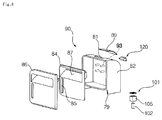
- the clothes treatment apparatus includes a cabinet 10 and a door 20 configured to open and close the front of the cabinet 10.
- the interior of the cabinet 10 is partitioned into upper and lower interior parts by a partition plate 11.
- a treatment chamber 12, in which clothes are hung, is defined in the interior of the cabinet 10 above the partition plate 11.
- a cycle chamber 14, in which machinery is installed, is defined in the interior of the cabinet 10 below the partition plate 11.
- Clothes are hung in the treatment chamber 12.
- wrinkles in the clothes are smoothed, or the clothes are deodorized, by the circulation of steam or air.
- a blowing unit 30 for circulating air in the treatment chamber 12, a steam unit 40 for supplying steam into the treatment chamber 12, a heat pump unit 50 for conditioning air in the treatment chamber 12, and a control unit 60 for controlling the respective units 30, 40, and 50 are installed in the cycle chamber 14.
- an assembly of machinery including the blowing unit 30, the steam unit 40, the heat pump unit 50, and the control unit 60, which are required to perform respective cycles of the clothes treatment apparatus, is defined as a cycle assembly.
- the blowing unit 30 includes a blowing fan 32 and an inlet duct 34.
- the inlet duct 34 is installed at the suction side of the blowing fan 32 to guide air in the treatment chamber 12 to the blowing fan 32.
- the blowing fan 32 is rotated to blow air.
- the blowing fan 32 suctions air from the treatment chamber 12, and discharges the suctioned air to the heat pump unit 50.
- the steam unit 40 When the steam unit 40 is powered on, heat is generated from the steam unit 40.
- the steam unit 40 converts water supplied from a water supply tank 80, which will be described hereinafter, into steam.
- the generated steam is discharged into the treatment chamber 12.
- a flow channel is defined such that the steam flows into the treatment chamber 12 via the heat pump unit 50.
- the heat pump unit 50 constitutes a heat pump cycle including a compressor, a condenser, an evaporator, and an expansion valve. Based on the operation mode of the heat pump unit 50, cooled air or heated air may be discharged into the treatment chamber 12.
- the heat pump unit 50 may dehumidify air supplied from the blowing unit 30.
- a tank module 70 for storing water is installed in front of the cycle chamber 14.
- the tank module 70 includes a water supply tank 80 for supplying water to the steam unit 40 and a drainage tank 90 for gathering and storing condensed water that is generated in the treatment chamber 12.
- Water from the water supply tank 80 flows to the steam unit 40 via a water supply pump 45.
- Water that is condensed in the treatment chamber 12 flows to the lower side of the treatment chamber 12 due to gravity, and is then pumped to the drainage tank 90 by a drainage pump 46. Water that is condensed in the heat pump unit 50 also flows to the drainage tank 90 via the drainage pump 46.
- the water supply pump 45 or the drainage pump 46 is controlled by the control unit 60.
- a tank module frame 71 is installed in front of the inlet duct 34.
- a tank installation space 73 is defined between the tank module frame 71 and the door 20.
- the tank module frame 71 is coupled to the partition plate 11 to isolate the cycle chamber 14 from the outside.
- a tank support bar 75 which interferes with at least one selected from between the water supply tank 80 and the drainage tank 90, is installed in front of the tank installation space 73.
- the tank support bar 75 prevents the water supply tank 80 or the drainage tank 90 from being unintentionally separated from the tank installation space 73.
- the tank support bar 75 supports the front of the water supply tank 80 and the front of the drainage tank 90.
- the lower end of the water supply tank 80 is placed on the upper end of the tank support bar 75, and the lower end of the drainage tank 90 is placed on the upper end of the tank support bar 75.
- a tank support end 79, which interferes with the tank support bar 75, is formed on at least one selected from between the water supply tank 80 and the drainage tank 90.
- the tank support end 79 is concavely recessed.
- the front of the tank support bar 75 and the front of the water supply tank 80 may form a continuous surface due to the tank support end 79.
- the front of the tank support bar 75 and the front of the drainage tank 90 may form a continuous surface due to the tank support end 79.
- the water supply tank 80 and the drainage tank 90 are disposed in the tank installation space 73 such that the water supply tank 80 and the drainage tank 90 are arranged parallel to each other in rightward and leftward directions.
- the water supply tank 80 and the drainage tank 90 are exposed to a user.
- the water supply tank 80 and the drainage tank 90 may be withdrawn by the user.
- the water supply tank 80 and the drainage tank 90 may be separated from the tank module frame 71.
- the water supply tank 80 and the drainage tank 90 may be separably mounted in the tank installation space 73.
- the water supply tank 80 is connected to the steam unit 40 to supply water to the steam unit 40.
- the drainage tank 90 is connected to the treatment chamber 12 to store water discharged from the treatment chamber 12 or the heat pump unit 50.
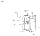
- the water supply tank 80 includes a tank body 82, which is open at the front thereof, a tank cover 84 coupled to the front of the tank body 82, a decorative cover 86 coupled to the tank cover 84, a water supply check valve 110 installed in the tank body 82 for opening and closing a flow channel connected with the steam unit 40, and a water supply level sensor 100 for sensing the level of water stored in the tank body 82.
- the front of the tank body 82 is open.
- the water supply level sensor 100 is disposed in the tank body 82.
- the upper end of the tank body 82 is round at the rear side thereof.
- the user may easily pull and withdraw the water tank 80, which is disposed at the lower side of the clothes treatment apparatus, due to the round shape of the tank body 82.
- the water supply level sensor 100 includes a float 102 installed in the tank body 82 such that the float 102 can move upward and downward based on the level of water stored in the tank body 82, a float cabinet 105 installed in the tank body 82 in a state in which the float 102 is disposed in the float cabinet 105, and a sensor 104 installed at the tank module frame 71 to sense the float 102.
- the float 102 has a magnet.
- the sensor 104 senses the magnetic force of the magnet.
- the sensor 104 may be installed at the front or rear of the tank module frame 71.
- the sensor 104 may be installed through the tank module frame 71.
- the sensor 104 may be located in any one selected from among the cycle chamber 14, the tank installation space 73, and the tank module frame 71.
- the float 102 which is installed in the water supply tank 80, is flush with the sensor 104.
- the float 102 moves lower than the sensor 104.
- the control unit 60 outputs a water deficiency signal. Even when the water deficiency signal is output, it is possible to supply a sufficient amount of steam during a cycle that is currently being performed.
- control unit 60 may determine whether the water supply tank 80 is mounted.
- control unit 60 when the water supply tank 80 is not mounted, or when water is deficient, the control unit 60 outputs a water deficiency signal.
- the control unit 60 When the user manipulates the clothes treatment apparatus in a state in which the water deficiency signal is output, therefore, the control unit 60 performs control such that the clothes treatment apparatus is not operated and outputs a water deficiency signal. At this time, the user may check the water supply tank 80.
- a float installation part 83, at which the float 102 is installed, is formed at the inside of the tank body 82.
- the float cabinet 105 is installed at the float installation part 83.
- the float 102 may move upward and downward along the float cabinet 105 by buoyancy.
- the float 102 is installed at the minimum level of water stored in the water supply tank 80, at which it is possible to supply an amount of steam corresponding to one cycle. Even when the sensor 104 fails to sense the float 102, and therefore the control unit 60 outputs a water deficiency signal, it is possible to supply an amount of steam corresponding to at least one cycle.
- the float cabinet 105 in which the float 102 is mounted, is manufactured by insert injection molding at the time of die slide injection (DSI) of the tank cover 84 and the tank body 82.
- DSI die slide injection
- DSI Die slide injection
- the tank body 82 and the tank cover 84 are manufactured by insert injection molding using DSI.
- the float cabinet 105 is installed in the tank body 82 and the tank cover 84 by insert injection molding.
- the edge of the tank cover 84 is integrally coupled to the edge of the tank body 82.
- the tank cover 84 has a window 85, through which the user may check the level of water in the tank body 82.
- a grip 87 into which the user may insert his/her hand in order to hold the tank cover 84, is concavely formed at the tank cover 84.
- the grip 87 is formed at the tank cover 84 such that the grip 87 is concave from the front to the rear thereof.
- a sensor fixing part 88 is formed at the inside of the tank cover 84.
- the sensor fixing part 88 protrudes from the inside of the tank cover 84. When the tank cover 84 and the tank body 82 are coupled to each other, the sensor fixing part 88 comes into tight contact with the float cabinet 105.
- the float cabinet 105 Since the sensor fixing part 88 tightly contacts the float cabinet 105, the float cabinet 105 is prevented from being separated from the float installation part 83.
- the sensor fixing part 88 may be integrally formed with the tank cover 84.
- the decorative cover 86 is formed to have a shape that is capable of covering the front of the tank cover 84. In addition, the decorative cover 86 is formed to have a shape corresponding to the shape of the tank cover 84.
- a water hole 81 is formed at the upper side of the tank body 82.
- a water hole cover 89 for opening and closing the water hole 81 is disposed at the upper side of the tank body 82.
- the water hole cover 89 is made of a flexible material exhibiting high elasticity. One end of the water hole cover 89 is fixed to the tank body 82, and the other end of the water hole cover 89 may be bent in order to open and close the water hole 82.
- the water supply check valve 110 includes a check valve hole 111 formed at the lower side of the tank body 82 and a check assembly 112 coupled to the check valve hole 111 for regulating the water in the tank body 82.
- the check assembly 112 includes a check housing 113 coupled into the check valve hole 111, the check housing 113 having a check flow channel 114, through which water flows into the check housing 113, a valve 115 disposed in the check housing 113 for opening and closing the check flow channel 114, and a check elastic member 116 disposed between the valve 115 and the tank body 82 for applying elastic force to the valve 115.
- valve 115 protrudes downward.
- the valve 115 may be pushed by the tank module frame 71, and may thus move upward.
- the check flow channel 114 is opened as the result of the movement of the valve 115.
- the check flow channel 114 is closed by the elastic force of the check elastic member 116.
- the drainage tank 90 is identical in function to the water supply tank 80.
- the drainage tank 90 is disposed alongside the water supply tank 80.
- a drainage check valve 120 is installed at the rear side thereof, not at the lower side thereof, unlike the water supply tank 80.
- the water supply tank 80 receives water through the water hole 81, and discharges water through the water supply check valve 110.
- the drainage tank 90 may receive condensed water through the drainage check valve 120, and may discharge condensed water through the water hole 81.
- the drainage check valve 120 of the drainage tank 90 may be disposed in a channel for receiving condensed water, not for discharging condensed water.
- condensed water may fall into the drainage tank 90 through the water hole 81.
- condensed water may be automatically discharged through the drainage check valve 120.
- Water that is condensed in the treatment chamber 12 and water that is condensed in the heat pump unit 50 are stored in the drainage tank 90.
- the float installation part 93 may be located at a height in the drainage tank 90 at which overflow does not occur even when an amount of condensed water that is generated during one cycle is stored therein.
- the float installation part 93 is located at a height in the drainage tank 90 at which overflow does not occur even when an amount of condensed water that is generated during one cycle is stored in the drainage tank 90.
- a drainage level sensor 101 of the drainage tank 90 senses a signal during the operation of the clothes treatment apparatus, therefore, the water in the drainage tank 90 does not overflow due to the condensed water that is additionally stored in the drainage tank 90.
- the drainage level sensor 101 of the drainage tank 90 is located higher than the water supply level sensor 100 in the water supply tank 80.
- the drainage level sensor 101 of the drainage tank 90 is identical in construction to the water supply level sensor 100 of the water supply tank 80. However, the drainage level sensor 101 of the drainage tank 90 is operated differently from the water supply level sensor 100 of the water supply tank 80.
- the senor 104 of the drainage tank 90 does not sense the float 102 in a normal state.
- the sensor 104 of the drainage tank 90 senses the float 102, which has been raised by buoyancy.
- the control unit 60 When the sensor 104 of the drainage tank 90 senses the float 102, the control unit 60 outputs a water drainage signal. When the water drainage signal is output, however, the overflow of condensed water does not occur during a cycle that is currently being performed.
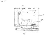
- a lower cabinet 130 on which the water supply tank 80 and the drainage tank 90 are mounted, is disposed at the lower side of the tank installation space 73.
- the lower cabinet 130 defines the tank installation space 73 together with the tank module frame 71.
- the lower cabinet 130 is an element that defines the lower part of the cabinet 10.
- the lower cabinet 130 is assembled with the tank module frame 71 to support the water supply tank 80 and the drainage tank 90.
- the lower cabinet 130 is an element that constitutes the cabinet 10.
- the lower cabinet 130 is provided with a flow channel, which connects the water supply tank 80 and the steam unit 40 to each other.
- the tank module frame 71 is provided with a flow channel, which connects the drainage tank 90 and the heat pump unit 50 to each other.
- the lower cabinet 130 includes a lower base 132, on which the water supply tank 80 and the drainage tank 90 are mounted, and a lower back 134 connected to the lower base 132, the lower back 134 being assembled with the tank module frame 71.
- a lower partition wall 136 is further provided to partition the lower base 132 into left and right base parts.
- One part of the lower base 132 partitioned by the lower partition wall 136 is defined as a first installation part 131, and the other part of the lower base 132 partitioned by the lower partition wall 136 is defined as a second installation part 133.
- the water supply tank 80 is mounted on the first installation part 131, and the drainage tank 90 is mounted on the second installation part 133.
- the lower partition wall 136 may not be provided.
- the lower back 134 forms a continuous surface with the tank module frame 71.
- the lower back 134 separates the cycle chamber 14 and the tank installation space 73 from each other together with the tank module frame 71.
- the lower back 134 is disposed perpendicular to the lower partition wall 136.
- the lower partition wall 136 partitions an installation space for the water supply tank 80 and an installation space for the drainage tank 90 from each other. In addition, the lower partition wall 136 prevents the water supply tank 80 or the drainage tank 90 from interfering with the drainage tank 90 or the water supply tank 80 when the water supply tank 80 or the drainage tank 90 is separated.
- the water supply tank 80 when the water supply tank 80 is shaken or lifted, a small amount of water from the water supply check valve 110 may be discharged into a receiving space 141.
- the water from the water supply check valve 110 When the water from the water supply check valve 110 is repeatedly discharged into the receiving space 141, the water may overflow the receiving space 141. As a result, the water may overflow a water pocket 140.
- the lower partition wall 136 functions to prevent interference between the water supply tank 80 and the drainage tank 90, which are adjacent to each other.
- the water pocket 140 is disposed on the first installation part 131.
- the water supply tank 80 is coupled to the water pocket 140.
- the water supply check valve 110 of the water supply tank 80 is inserted into the water pocket 140.
- a flow channel for connecting the water supply tank 80 and the steam unit 40 to each other is defined.
- the water pocket 140 stores a predetermined amount of water discharged from the water supply check valve 110.
- the water pocket 140 includes a pocket housing 142 formed at the lower base 132 such that the pocket housing 142 protrudes upward from the lower base 132, a water hole 145 formed at the pocket housing 142, the water hole 145 being provided with a flow channel communicating with the steam unit 40, and a water barrier 146 formed at the pocket housing 142, the water barrier 146 defining the receiving space 141 inside the pocket housing 142.
- the water hole 145 is formed inside the pocket housing 142.
- the pocket housing 142 is coupled with the water supply check valve 110 of the water supply tank 80.
- the pocket housing 142 supports the water supply tank 80.
- the water barrier 146 protrudes upward from the pocket housing 142.
- the pocket housing 142 may be recessed to define the receiving space 141.
- a small amount of water may be stored in the receiving space 141.
- the water hole 145 is located inside the receiving space 141.
- the water stored in the receiving space 141 may flow to the steam unit 40 via the water hole 145.
- the receiving space 141 is formed so as to be open toward the tank installation space 73.
- the water supply tank 80 may be mounted on the water barrier 146 such that the water supply tank 80 is supported by the water barrier 146.
- water discharged through the water supply check valve 110 may overflow the water pocket 140.
- the present invention provides a control method that is capable of moving water stored in the receiving space 141 to the steam unit 40. As a result, it is possible to prevent water in the receiving space 141 from overflowing the receiving space 141 when the water supply tank 80 is repeatedly separated.
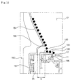
- the door 20 includes a door panel 22 for opening and closing the front of the cabinet 10, a hinge unit 24 for connecting the door panel 22 and the cabinet 10 in a hinged fashion, a door gasket 26 disposed at the door panel 22 such that the door gasket 26 is in tight contact with the edge of the cabinet 10 to achieve a seal between the door 20 and the cabinet 10, and a door liner 180 disposed at the inside of the door panel 2 for guiding condensed water that is generated in the treatment chamber 12 to the partition plate 11.
- the door 20 is configured to have a structure that simultaneously opens and closes the treatment chamber 12 and the tank installation space 73.
- a plurality of doors may be mounted to the cabinet 10 such that the respective doors can open and close the treatment chamber 12 and the tank installation space 73.
- the door liner 180 is disposed toward the treatment chamber 12.
- the door liner 180 guides condensed water that is generated on the surface thereof to a drainage grill 13 formed at the partition plate 11.
- the door liner 180 includes a liner part 182, which is attached to the inside of the door panel 22 such that the liner part 182 is parallel to the door panel 22, and a liner guide part 184, which is formed at the lower end of the liner part 182 such that the liner guide part 184 is deviated toward the inside of the treatment chamber 12.
- the door liner 180 is located at the upper side of the partition plate 11.
- the door liner 180 may have an area slightly less than the area of the front of the treatment chamber 12.
- the door gasket 26 may be mounted to the door panel 22 such that the door gasket 26 surrounds the door panel 22.
- the seal between the door 20 and the cabinet 10 may be achieved by the door gasket 26.
- the door gasket 26 may individually seal the treatment chamber 12 and the tank installation space 73.
- the door gasket 26 may prevent condensed water that is generated in the treatment chamber 12 from flowing to the tank installation space 73.
- the liner part 182 is in tight contact with the door panel 22.
- the liner guide part 184 is integrally formed with the liner part 182. Unlike this embodiment, the liner part 182 and the liner guide part 184 may be manufactured separately.
- the liner guide part 184 is disposed such that the liner guide part 184 is deviated from the liner part 182 toward the treatment chamber 12.
- the liner guide part 184 may be formed to have a round shape or an inclined surface.
- the liner guide part 184 may protrude from the door 20 toward the inside of the treatment chamber 12.
- a drop part 186 is formed at the lower end of the liner guide part 184.
- the drop part 186 may be formed to have an undercut shape.
- the drop part 186 functions to increase the size of droplets of condensed water and to drop the droplets downward.
- a portion of the door gasket 26 may be disposed at the lower side of the liner guide part 184.
- the door gasket 26 prevents condensed water that is generated in the treatment chamber 12 from falling to the tank installation space 73.
- the condensed water moves along the liner guide part 184, and drops from the drop part 186.
- the dropped condensed water falls to a condensed water guide member 190, which is mounted to the partition plate 11.
- the condensed water guide member 190 moves the condensed water to the drainage grill 13, which is formed at the partition plate 11.
- the door gasket 26 is mounted to the rear of the door 20 such that the door gasket 26 is in tight contact with the front of the condensed water guide member 190.
- the door gasket 26 not only prevents the flow of water but also reduces impact applied to the door 20 when the door 20 is closed.
- the condensed water guide member 190 is disposed at the front of the drainage grill 13 such that the condensed water guide member 190 can be assembled to the partition plate 11.
- the condensed water guide member 190 is located at the upper side of the tank installation space 73.
- the drainage tank 90 and the water supply tank 80 are located at the lower side of the tank installation space 73.
- the condensed water guide member 190 is mounted to the front side end of the partition plate 11.
- the condensed water guide member 190 is located at the lower side of the drop part 186.
- the condensed water guide member 190 includes a guide member body 192 mounted to the partition plate 11, a guide surface 194 formed at the upper side surface of the guide member body 192 for guiding condensed water into the treatment chamber 12, and a coupling part 196 formed at the guide member body 192 for maintaining coupling force between the condensed water guide member 190 and the partition plate 11.
- the guide member body 192 covers a portion of the upper side surface of the partition plate 11.
- the guide member body 192 is formed to have a '[' shape that is open at the lower side.
- the coupling part 196 is formed to have a hook shape such that the coupling part 196 and the partition plate 11 are caught by each other.
- the drainage grill 13 is located at the inside of the partition plate 11.
- the drainage grill 13 is located at the inside of the treatment chamber 12.
- the guide surface 194 guides the condensed water to the drainage grill 13.
- the guide surface 194 is formed to have a backward slope that is inclined toward the inside of the treatment chamber 12.
- backward slope is a slope configured such that the front of the slope is high with respect to the cabinet 10 and the rear of the slope is low with respect to the cabinet 10.
- forward slope is a slope configured such that the front of the slope is low with respect to the cabinet 10 and the rear of the slope is high with respect to the cabinet 10.
- the condensed water dropped from the drop part 186 collides with the guide surface 194, and then moves to the drainage grill 13 along the slope of the guide surface 194.
- the condensed water guide member 190 extends in leftward and rightward directions. As a result, condensed water that flows along the inside wall of the treatment chamber 12 may also be guided to the drainage grill 13 along the guide surface 194.
- the guide surface 194 prevents the condensed water that has fallen along the treatment chamber 12 from flowing to the tank installation space 73.
- the partition plate 11 may be inclined toward the drainage grill 13.
- the drainage grill 13 may be located lower than other parts of the partition plate 11.
- Condensed water falling from the rear surface and the opposite side surfaces of the treatment chamber 12 may flow to the drainage grill 13 along the slope of the partition plate 11.
- the condensed water guide member 190 and the partition plate 11 are manufactured separately, and are then coupled to each other. This is because the direction of the slope of the guide surface 194, which constitutes the condensed water guide member 190, and the direction of the slope of the partition plate 11 are different from each other.
- the partition plate 11 is formed to have a forward slope toward the drainage grill 13, whereas the guide surface 194 is formed to have a backward slope.
- the condensed water guide member 190 and the partition plate 11 are manufactured separately such that the condensed water guide member 190 has a backward slope and the partition plate 11 has a forward slope. Consequently, the condensed water guide member 190 and the partition plate 11 may guide condensed water to the drainage grill 13.
- the condensed water guide structure which is constituted by the door liner 180 and the condensed water guide member 190, may minimize the protruding depth D of the door liner 180.
- the drop part 186 may be located at the upper side of the guide surface 96 rather than the upper side of the drainage grill 13.
- the protruding depth D of the drop part 186 may be minimized.
- the door gasket 26 is located lower than the guide surface 96 of the condensed water guide member 190. Unlike this embodiment, the upper side end of the door gasket 26 may be located higher than the guide surface 96. In this case, it is possible to more securely prevent the condensed water from flowing into the tank installation space 73.
- a gasket fixing part 87, to which the door gasket 26 is fixed, is provided at the door liner 180.
- the door gasket 26 is coupled and fixed to the gasket fixing part 87 in a hook fashion.
- a drainage channel (not shown) for guiding the condensed water from the drainage grill 13 to the drainage tank 90 is disposed in the cycle chamber 14.
- the drainage pump 46 is mounted in the drainage channel.
- the condensed water that has fallen from the rear surface and the opposite side surfaces of the treatment chamber 12 is guided to the drainage grill 13 along the forward slope of the partition plate 11.
- the condensed water dropped onto the upper surface of the condensed water guide member 190 is guided to the drainage grill 13 along the adverse slope of the guide surface 194.
- the condensed water that has accumulated in the drainage grill 13 is temporarily stored in the drainage channel.
- the drainage pump 46 pumps the condensed water that has accumulated in the drainage channel to the drainage tank 90.
- the drainage channel is connected to the drainage check valve 120.
- the water pumped by the drainage pump 46 is stored in the drainage tank 90 through the drainage check valve 120.
- the sensor 104 senses the float 102, and transmits a sensing signal to the control unit 60.
- the clothes treatment apparatus according to the present invention has the following effects.
- condensed water dropped from the door liner drops onto the upper side of the condensed water guide member, and is then guided to the drainage grill, which is provided at the partition plate, along the condensed water guide member. Consequently, it is possible to easily discharge the condensed water.
- the guide surface of the condensed water guide member, onto which condensed water drops, is formed to have a backward slope. Consequently, it is possible to prevent the condensed water from flowing to the tank installation space.
- the partition plate and the condensed water guide member are inclined toward the drainage grill. Consequently, it is possible to easily gather condensed water.
- the drainage grill is disposed at the upper side of the drainage tank, in which condensed water is stored. Consequently, it is possible to minimize the movement distance of the condensed water.
- the drop part of the door liner is inserted and located in the treatment chamber. Consequently, it is possible to maximally prevent condensed water gathering on the drop part from dropping to the outside when the door is opened.
- the gasket is brought into tight contact with the front of the condensed water guide member in order to seal the treatment chamber. Consequently, it is possible to preventing condensed water in the treatment chamber from falling to the tank installation space.
Abstract
Description
- The present invention relates to a clothes treatment apparatus.
- Clothes treatment apparatuses are apparatuses that treat clothes, e.g. wash and dry clothes and smooth wrinkles in clothes, at home or at laundromats.
- Clothes treatment apparatuses may be classified into a washer for washing clothes, a dryer for drying clothes, a washer/dryer having both a washing function and a drying function, a refresher for refreshing clothes, and a steamer for removing unnecessary wrinkles in clothes.
- The refresher is an apparatus that keeps clothes comfortable and fresh. The refresher functions to dry clothes, to supply fragrance to clothes, to prevent the occurrence of static electricity in clothes, or to remove wrinkles from clothes.
- The steamer is an apparatus that simply supplies steam to clothes in order to remove wrinkles from the clothes. Unlike a general iron, the steamer removes wrinkles from the clothes without directly applying heat to the clothes.
- A clothes treatment apparatus having both functions of a refresher and a steamer may remove wrinkles from clothes received in the clothes treatment apparatus, and may additionally deodorize the clothes, using steam and hot air.
- An example of such a conventional treatment apparatus is disclosed in Korean Patent Application Publication No.
10-2014-0016093 - Therefore, the present invention has been made in view of the above problems, and it is an object of the present invention to provide a clothes treatment apparatus that is capable of preventing the leakage of condensed water that is generated in a cabinet to the outside.
- It is another object of the present invention to provide a clothes treatment apparatus that is capable of minimizing the protruding depth of a door liner, which is installed on the inside of a door to guide condensed water.
- The objects are solved by the independent claim. The dependent claims relate to further aspects of the invention.
- In accordance with an aspect of the present invention, the above and other objects can be accomplished by the provision of a clothes treatment apparatus including a cabinet that includes a treatment chamber for allowing clothes to be hung therein and a cycle chamber for allowing machinery to be installed therein, the cycle chamber being located at the lower side of the treatment chamber, a partition plate for partitioning the treatment chamber and the cycle chamber from each other, a door for opening and closing the cabinet, a door liner disposed on the inside of the door for guiding condensed water generated in the treatment chamber and dropping the condensed water to the upper side of the partition plate, and a condensed water guide member disposed at the partition plate for guiding the condensed water dropped from the door liner into the treatment chamber.
- The partition plate may be provided with a drainage grill for discharging the condensed water from the treatment chamber, and the condensed water guide member may be inclined toward the drainage grill.
- The condensed water guide member may be formed to have a backward slope having a high front and a low rear with respect to the cabinet.
- The partition plate may be formed to have a forward slope having a high rear and a low front with respect to the cabinet.
- The condensed water guide member may be mounted to the front side end of the partition plate.
- The clothes treatment apparatus may further include a gasket mounted to the door, wherein the gasket may come into tight contact with the condensed water guide member when the door is closed.
- The gasket may be disposed between the cabinet and the door for sealing the treatment chamber when the door is closed.
- The condensed water guide member may include a guide member body disposed at the partition plate and a guide surface formed at the upper side surface of the guide member body for guiding the condensed water dropped from the door liner into the treatment chamber, the guide surface being inclined to have a backward slope having a high front and a low rear with respect to the cabinet.
- The door liner may be provided with a drop part for allowing condensed water to drop therefrom, the drop part being located at the upper side of the partition plate.
- The drop part may be formed to have an undercut shape.
- At least a portion of the door liner may be inserted into the treatment chamber, and may be located at the upper side of the partition plate.
- The partition plate may be provided with a drainage grill for discharging the condensed water from the treatment chamber, and the door liner may be provided with a drop part for allowing the condensed water to drop therefrom, the drop part being located at the upper side of the condensed water guide member.
- The clothes treatment apparatus may further include a tank installation space disposed at the lower side of the partition plate such that the tank installation space is partitioned from the cycle chamber, the tank installation space being open toward the front of the cabinet, wherein the condensed water guide member may be located at the upper side of the tank installation space.
- The partition plate may be provided with a drainage grill for discharging the condensed water from the treatment chamber, and the door liner may be provided with a drop part for allowing the condensed water to drop therefrom, the drop part being located at the upper side of the condensed water guide member.
- The condensed water guide member may be provided with a guide surface for allowing the condensed water dropped from the drop part to fall thereto, the guide surface being formed to have a backward slope having a high front and a low rear with respect to the cabinet.
- The clothes treatment apparatus may further include a drainage tank installed in the tank installation space for storing condensed water, a drainage channel for connecting the drainage grill and the drainage tank to each other, and a drainage pump disposed in the drainage channel.
- The condensed water guide member may include a guide member body disposed at the partition plate and a guide surface formed at the upper side surface of the guide member body for guiding the condensed water dropped from the door liner into the treatment chamber, the guide surface being inclined to have a backward slope having a high front and a low rear with respect to the cabinet, and the door liner may include a liner part attached to the inside of the door panel and a liner guide part formed at the lower end of the liner part such that the liner guide part protrudes into the treatment chamber in a deviating fashion, the liner guide part being located at the upper side of the guide surface.
- The clothes treatment apparatus may further include a tank installation space disposed at the lower side of the partition plate such that the tank installation space is partitioned from the cycle chamber, the tank installation space being open toward the front of the cabinet, wherein the condensed water guide member may be located at the upper side of the tank installation space, and a gasket mounted to the door, wherein the gasket may come into tight contact with the condensed water guide member for preventing the condensed water in the treatment chamber from flowing into the tank installation space when the door is closed.
- The embodiments will be described in detail with reference to the following drawings in which like reference numerals refer to like elements wherein:
-
FIG. 1 is a perspective view of a clothes treatment apparatus according to a first embodiment of the present invention; -
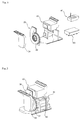
FIG. 2 is an exploded perspective view of a cycle assembly according to a first embodiment of the present invention; -
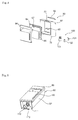
FIG. 3 is a perspective view of the cycle assembly according to the first embodiment of the present invention; -
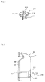
FIG. 4 is an exploded perspective view of a water supply tank shown inFIG. 1 ; -
FIG. 5 is a partially exploded perspective view of the water supply tank shown inFIG. 1 ; -
FIG. 6 is a sectional perspective view of a check assembly shown inFIG. 5 ; -
FIG. 7 is a side sectional view of the water supply tank shown inFIG. 1 ; -
FIG. 8 is a perspective view of a drainage tank shown inFIG. 1 ; -
FIG. 9 is a partially exploded perspective view of the drainage tank shown inFIG. 1 ; -
FIG. 10 is a side sectional view of the drainage tank shown inFIG. 1 ; -
FIG. 11 is a perspective view of a lower cabinet shown inFIG. 1 ; -
FIG. 12 is a perspective view of the lower cabinet shown inFIG. 11 ; -
FIG. 13 is a block diagram of the clothes treatment apparatus according to the first embodiment of the present invention; -
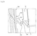
FIG. 14 is a side sectional view showing a coupled state of a door liner shown inFIG. 1 ; and -
FIG. 15 is an exploded perspective view of a condensed water guide member shown inFIG. 1 . - The present invention will be described in detail with reference to the accompanying drawings.
- In the following description of the present invention, a detailed description of known functions or configurations incorporated herein will be omitted when it may make the subject matter of the present invention rather unclear. The same terms may be denoted by different reference numerals if the terms indicate different parts.
- The terms used in the following description are terms defined taking into consideration the functions obtained in accordance with the present invention. The definitions of these terms should be determined based on the whole content of this specification because they may be changed in accordance with the intentions of users, such as experimenters and measurers, or usual practices.
- In this specification, the terms "first," "second," etc. are used to describe various elements. However, the elements are not limited by the terms. The terms are used only to distinguish one element from another element. For example, a first element may be named a second element, and a second element may be named a first element, without departing from the scope of right of the present invention. It will be understood that the term "and/or" refers to one or more possible combinations of specified relevant items and includes such combinations.
- The terms used in this specification are provided only to explain specific embodiments, but are not intended to restrict the present invention. A singular representation may include a plural representation unless it represents a definitely different meaning from the context.
- Unless otherwise defined, all terms, including technical and scientific terms, used in this specification have the same meaning as commonly understood by a person having ordinary skill in the art to which the present invention pertains. It will be further understood that terms, such as those defined in commonly used dictionaries, should be interpreted as having a meaning that is consistent with their meaning in the context of the relevant art and the present disclosure, and will not be interpreted in an idealized or overly formal sense unless expressly so defined herein.
- In addition, the terms "comprises" and "includes" described herein should be interpreted not to exclude other elements but to further include such other elements since the corresponding elements may be inherent unless mentioned otherwise.
- Hereinafter, a clothes treatment apparatus according to a first embodiment of the present invention will be described with reference to
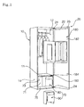
FIGS. 1 to 13 . - The clothes treatment apparatus according to this embodiment includes a
cabinet 10 and adoor 20 configured to open and close the front of thecabinet 10. - The interior of the
cabinet 10 is partitioned into upper and lower interior parts by apartition plate 11. Atreatment chamber 12, in which clothes are hung, is defined in the interior of thecabinet 10 above thepartition plate 11. Acycle chamber 14, in which machinery is installed, is defined in the interior of thecabinet 10 below thepartition plate 11. - Clothes are hung in the
treatment chamber 12. In thetreatment chamber 12, wrinkles in the clothes are smoothed, or the clothes are deodorized, by the circulation of steam or air. - A blowing
unit 30 for circulating air in thetreatment chamber 12, asteam unit 40 for supplying steam into thetreatment chamber 12, aheat pump unit 50 for conditioning air in thetreatment chamber 12, and acontrol unit 60 for controlling therespective units cycle chamber 14. - In this embodiment, an assembly of machinery, including the
blowing unit 30, thesteam unit 40, theheat pump unit 50, and thecontrol unit 60, which are required to perform respective cycles of the clothes treatment apparatus, is defined as a cycle assembly. - The blowing
unit 30 includes a blowingfan 32 and aninlet duct 34. - The
inlet duct 34 is installed at the suction side of the blowingfan 32 to guide air in thetreatment chamber 12 to the blowingfan 32. - The blowing
fan 32 is rotated to blow air. The blowingfan 32 suctions air from thetreatment chamber 12, and discharges the suctioned air to theheat pump unit 50. - When the
steam unit 40 is powered on, heat is generated from thesteam unit 40. Thesteam unit 40 converts water supplied from awater supply tank 80, which will be described hereinafter, into steam. The generated steam is discharged into thetreatment chamber 12. - In this embodiment, a flow channel is defined such that the steam flows into the
treatment chamber 12 via theheat pump unit 50. - The
heat pump unit 50 constitutes a heat pump cycle including a compressor, a condenser, an evaporator, and an expansion valve. Based on the operation mode of theheat pump unit 50, cooled air or heated air may be discharged into thetreatment chamber 12. - In particular, the
heat pump unit 50 may dehumidify air supplied from the blowingunit 30. - A tank module 70 for storing water is installed in front of the
cycle chamber 14. The tank module 70 includes awater supply tank 80 for supplying water to thesteam unit 40 and adrainage tank 90 for gathering and storing condensed water that is generated in thetreatment chamber 12. - Water from the
water supply tank 80 flows to thesteam unit 40 via awater supply pump 45. - Water that is condensed in the
treatment chamber 12 flows to the lower side of thetreatment chamber 12 due to gravity, and is then pumped to thedrainage tank 90 by adrainage pump 46. Water that is condensed in theheat pump unit 50 also flows to thedrainage tank 90 via thedrainage pump 46. - The
water supply pump 45 or thedrainage pump 46 is controlled by thecontrol unit 60. - In this embodiment, a
tank module frame 71 is installed in front of theinlet duct 34. - A
tank installation space 73 is defined between thetank module frame 71 and thedoor 20. Thetank module frame 71 is coupled to thepartition plate 11 to isolate thecycle chamber 14 from the outside. - A
tank support bar 75, which interferes with at least one selected from between thewater supply tank 80 and thedrainage tank 90, is installed in front of thetank installation space 73. - The
tank support bar 75 prevents thewater supply tank 80 or thedrainage tank 90 from being unintentionally separated from thetank installation space 73. Thetank support bar 75 supports the front of thewater supply tank 80 and the front of thedrainage tank 90. - When the
door 20 is opened and closed, therefore, thewater supply tank 80 and thedrainage tank 90 are prevented from being separated from thetank installation space 73. - In this embodiment, the lower end of the
water supply tank 80 is placed on the upper end of thetank support bar 75, and the lower end of thedrainage tank 90 is placed on the upper end of thetank support bar 75. - A
tank support end 79, which interferes with thetank support bar 75, is formed on at least one selected from between thewater supply tank 80 and thedrainage tank 90. - The
tank support end 79 is concavely recessed. - The front of the
tank support bar 75 and the front of thewater supply tank 80 may form a continuous surface due to thetank support end 79. In addition, the front of thetank support bar 75 and the front of thedrainage tank 90 may form a continuous surface due to thetank support end 79. - The
water supply tank 80 and thedrainage tank 90 are disposed in thetank installation space 73 such that thewater supply tank 80 and thedrainage tank 90 are arranged parallel to each other in rightward and leftward directions. - When the
door 20 is opened, thewater supply tank 80 and thedrainage tank 90 are exposed to a user. - The
water supply tank 80 and thedrainage tank 90 may be withdrawn by the user. - The
water supply tank 80 and thedrainage tank 90 may be separated from thetank module frame 71. Thewater supply tank 80 and thedrainage tank 90 may be separably mounted in thetank installation space 73. - The
water supply tank 80 is connected to thesteam unit 40 to supply water to thesteam unit 40. Thedrainage tank 90 is connected to thetreatment chamber 12 to store water discharged from thetreatment chamber 12 or theheat pump unit 50. - The
water supply tank 80 includes atank body 82, which is open at the front thereof, atank cover 84 coupled to the front of thetank body 82, adecorative cover 86 coupled to thetank cover 84, a watersupply check valve 110 installed in thetank body 82 for opening and closing a flow channel connected with thesteam unit 40, and a watersupply level sensor 100 for sensing the level of water stored in thetank body 82. - The front of the
tank body 82 is open. The watersupply level sensor 100 is disposed in thetank body 82. - The upper end of the
tank body 82 is round at the rear side thereof. - When the
tank body 82 is separated, interference between thetank body 82 and thepartition plate 11 is minimized. - The user may easily pull and withdraw the
water tank 80, which is disposed at the lower side of the clothes treatment apparatus, due to the round shape of thetank body 82. - In this embodiment, the water
supply level sensor 100 includes afloat 102 installed in thetank body 82 such that thefloat 102 can move upward and downward based on the level of water stored in thetank body 82, afloat cabinet 105 installed in thetank body 82 in a state in which thefloat 102 is disposed in thefloat cabinet 105, and asensor 104 installed at thetank module frame 71 to sense thefloat 102. - The
float 102 has a magnet. Thesensor 104 senses the magnetic force of the magnet. - The
sensor 104 may be installed at the front or rear of thetank module frame 71. - The
sensor 104 may be installed through thetank module frame 71. - Consequently, the
sensor 104 may be located in any one selected from among thecycle chamber 14, thetank installation space 73, and thetank module frame 71. - The
float 102, which is installed in thewater supply tank 80, is flush with thesensor 104. When the level of water stored in thewater supply tank 80 is lowered, thefloat 102 moves lower than thesensor 104. When thesensor 104 fails to sense thefloat 102, therefore, thecontrol unit 60 outputs a water deficiency signal. Even when the water deficiency signal is output, it is possible to supply a sufficient amount of steam during a cycle that is currently being performed. - Since the
sensor 104 constantly senses thefloat 102, thecontrol unit 60 may determine whether thewater supply tank 80 is mounted. - For example, when the
water supply tank 80 is not mounted, or when water is deficient, thecontrol unit 60 outputs a water deficiency signal. - When the user manipulates the clothes treatment apparatus in a state in which the water deficiency signal is output, therefore, the
control unit 60 performs control such that the clothes treatment apparatus is not operated and outputs a water deficiency signal. At this time, the user may check thewater supply tank 80. - A
float installation part 83, at which thefloat 102 is installed, is formed at the inside of thetank body 82. Thefloat cabinet 105 is installed at thefloat installation part 83. Thefloat 102 may move upward and downward along thefloat cabinet 105 by buoyancy. - In this embodiment, the
float 102 is installed at the minimum level of water stored in thewater supply tank 80, at which it is possible to supply an amount of steam corresponding to one cycle. Even when thesensor 104 fails to sense thefloat 102, and therefore thecontrol unit 60 outputs a water deficiency signal, it is possible to supply an amount of steam corresponding to at least one cycle. - That is, even when a water deficiency signal is sensed during the supply of steam, it is possible to supply a sufficient amount of steam until a cycle that is currently being performed is completed.
- The
float cabinet 105, in which thefloat 102 is mounted, is manufactured by insert injection molding at the time of die slide injection (DSI) of thetank cover 84 and thetank body 82. - Die slide injection (DSI) is a molding technology that has been developed for blow molding or molding of thin products. DSI conveys various advantages in that no post-processing, such as adhesion or assembly, is necessary after injection molding, it is possible to adjust the thickness of a wall more easily than when blow molding or gas molding, it is possible to provide an excellent surface shape or high dimensional accuracy, and it is possible to perform DSI more easily than double injection or blow molding. The manufacture of products using DSI is ordinarily known in the art to which the present invention pertains, and therefore a detailed description thereof will be omitted.
- The
tank body 82 and thetank cover 84 are manufactured by insert injection molding using DSI. During the manufacture of thetank body 82 and thetank cover 84, thefloat cabinet 105 is installed in thetank body 82 and thetank cover 84 by insert injection molding. During the manufacture of thetank body 82 and thetank cover 84, the edge of thetank cover 84 is integrally coupled to the edge of thetank body 82. - The tank cover 84 has a
window 85, through which the user may check the level of water in thetank body 82. In addition, agrip 87, into which the user may insert his/her hand in order to hold thetank cover 84, is concavely formed at thetank cover 84. - The
grip 87 is formed at thetank cover 84 such that thegrip 87 is concave from the front to the rear thereof. - A
sensor fixing part 88 is formed at the inside of thetank cover 84. Thesensor fixing part 88 protrudes from the inside of thetank cover 84. When thetank cover 84 and thetank body 82 are coupled to each other, thesensor fixing part 88 comes into tight contact with thefloat cabinet 105. - Since the
sensor fixing part 88 tightly contacts thefloat cabinet 105, thefloat cabinet 105 is prevented from being separated from thefloat installation part 83. - The
sensor fixing part 88 may be integrally formed with thetank cover 84. - The
decorative cover 86 is formed to have a shape that is capable of covering the front of thetank cover 84. In addition, thedecorative cover 86 is formed to have a shape corresponding to the shape of thetank cover 84. - A
water hole 81 is formed at the upper side of thetank body 82. In addition, awater hole cover 89 for opening and closing thewater hole 81 is disposed at the upper side of thetank body 82. - The
water hole cover 89 is made of a flexible material exhibiting high elasticity. One end of thewater hole cover 89 is fixed to thetank body 82, and the other end of thewater hole cover 89 may be bent in order to open and close thewater hole 82. - The water
supply check valve 110 includes acheck valve hole 111 formed at the lower side of thetank body 82 and acheck assembly 112 coupled to thecheck valve hole 111 for regulating the water in thetank body 82. - The
check assembly 112 includes acheck housing 113 coupled into thecheck valve hole 111, thecheck housing 113 having acheck flow channel 114, through which water flows into thecheck housing 113, avalve 115 disposed in thecheck housing 113 for opening and closing thecheck flow channel 114, and a checkelastic member 116 disposed between thevalve 115 and thetank body 82 for applying elastic force to thevalve 115. - The small-diameter side of the
valve 115 protrudes downward. When thevalve 115 is placed on thetank module frame 71, thevalve 115 may be pushed by thetank module frame 71, and may thus move upward. At this time, thecheck flow channel 114 is opened as the result of the movement of thevalve 115. When thewater supply tank 80 is separated from thetank module frame 71, thecheck flow channel 114 is closed by the elastic force of the checkelastic member 116. - The
drainage tank 90 is identical in function to thewater supply tank 80. Thedrainage tank 90 is disposed alongside thewater supply tank 80. - In the
drainage tank 90, adrainage check valve 120 is installed at the rear side thereof, not at the lower side thereof, unlike thewater supply tank 80. - The
water supply tank 80 receives water through thewater hole 81, and discharges water through the watersupply check valve 110. Thedrainage tank 90 may receive condensed water through thedrainage check valve 120, and may discharge condensed water through thewater hole 81. - That is, the
drainage check valve 120 of thedrainage tank 90 may be disposed in a channel for receiving condensed water, not for discharging condensed water. - Unlike this embodiment, condensed water may fall into the
drainage tank 90 through thewater hole 81. In addition, condensed water may be automatically discharged through thedrainage check valve 120. - Water that is condensed in the
treatment chamber 12 and water that is condensed in theheat pump unit 50 are stored in thedrainage tank 90. - A
float installation part 93, at which thefloat cabinet 105 is installed, is formed in thedrainage tank 90. - The
float installation part 93 may be located at a height in thedrainage tank 90 at which overflow does not occur even when an amount of condensed water that is generated during one cycle is stored therein. - That is, the
float installation part 93 is located at a height in thedrainage tank 90 at which overflow does not occur even when an amount of condensed water that is generated during one cycle is stored in thedrainage tank 90. - When a
drainage level sensor 101 of thedrainage tank 90 senses a signal during the operation of the clothes treatment apparatus, therefore, the water in thedrainage tank 90 does not overflow due to the condensed water that is additionally stored in thedrainage tank 90. - The
drainage level sensor 101 of thedrainage tank 90 is located higher than the watersupply level sensor 100 in thewater supply tank 80. - The
drainage level sensor 101 of thedrainage tank 90 is identical in construction to the watersupply level sensor 100 of thewater supply tank 80. However, thedrainage level sensor 101 of thedrainage tank 90 is operated differently from the watersupply level sensor 100 of thewater supply tank 80. - For example, the
sensor 104 of thedrainage tank 90 does not sense thefloat 102 in a normal state. When the level of condensed water rises, thesensor 104 of thedrainage tank 90 senses thefloat 102, which has been raised by buoyancy. - When the
sensor 104 of thedrainage tank 90 senses thefloat 102, thecontrol unit 60 outputs a water drainage signal. When the water drainage signal is output, however, the overflow of condensed water does not occur during a cycle that is currently being performed. - Meanwhile, a
lower cabinet 130, on which thewater supply tank 80 and thedrainage tank 90 are mounted, is disposed at the lower side of thetank installation space 73. Thelower cabinet 130 defines thetank installation space 73 together with thetank module frame 71. - The
lower cabinet 130 is an element that defines the lower part of thecabinet 10. Thelower cabinet 130 is assembled with thetank module frame 71 to support thewater supply tank 80 and thedrainage tank 90. - Hereinafter, the
lower cabinet 130 will be described in detail with reference toFIGS. 11 and12 . - The
lower cabinet 130 is an element that constitutes thecabinet 10. - In this embodiment, the
lower cabinet 130 is provided with a flow channel, which connects thewater supply tank 80 and thesteam unit 40 to each other. In this embodiment, thetank module frame 71 is provided with a flow channel, which connects thedrainage tank 90 and theheat pump unit 50 to each other. - The
lower cabinet 130 includes alower base 132, on which thewater supply tank 80 and thedrainage tank 90 are mounted, and a lower back 134 connected to thelower base 132, the lower back 134 being assembled with thetank module frame 71. - In this embodiment, a
lower partition wall 136 is further provided to partition thelower base 132 into left and right base parts. One part of thelower base 132 partitioned by thelower partition wall 136 is defined as afirst installation part 131, and the other part of thelower base 132 partitioned by thelower partition wall 136 is defined as asecond installation part 133. - In this embodiment, the
water supply tank 80 is mounted on thefirst installation part 131, and thedrainage tank 90 is mounted on thesecond installation part 133. Unlike this embodiment, thelower partition wall 136 may not be provided. - The lower back 134 forms a continuous surface with the
tank module frame 71. - The
lower back 134 separates thecycle chamber 14 and thetank installation space 73 from each other together with thetank module frame 71. - The
lower back 134 is disposed perpendicular to thelower partition wall 136. - The
lower partition wall 136 partitions an installation space for thewater supply tank 80 and an installation space for thedrainage tank 90 from each other. In addition, thelower partition wall 136 prevents thewater supply tank 80 or thedrainage tank 90 from interfering with thedrainage tank 90 or thewater supply tank 80 when thewater supply tank 80 or thedrainage tank 90 is separated. - As will be described hereinafter, when the
water supply tank 80 is shaken or lifted, a small amount of water from the watersupply check valve 110 may be discharged into a receivingspace 141. When the water from the watersupply check valve 110 is repeatedly discharged into the receivingspace 141, the water may overflow the receivingspace 141. As a result, the water may overflow awater pocket 140. Thelower partition wall 136 functions to prevent interference between thewater supply tank 80 and thedrainage tank 90, which are adjacent to each other. - In this embodiment, the
water pocket 140 is disposed on thefirst installation part 131. - The
water supply tank 80 is coupled to thewater pocket 140. - The water
supply check valve 110 of thewater supply tank 80 is inserted into thewater pocket 140. - When the water
supply check valve 110 is inserted into thewater pocket 140, a flow channel for connecting thewater supply tank 80 and thesteam unit 40 to each other is defined. - The
water pocket 140 stores a predetermined amount of water discharged from the watersupply check valve 110. - The
water pocket 140 includes apocket housing 142 formed at thelower base 132 such that thepocket housing 142 protrudes upward from thelower base 132, awater hole 145 formed at thepocket housing 142, thewater hole 145 being provided with a flow channel communicating with thesteam unit 40, and awater barrier 146 formed at thepocket housing 142, thewater barrier 146 defining the receivingspace 141 inside thepocket housing 142. - The
water hole 145 is formed inside thepocket housing 142. Thepocket housing 142 is coupled with the watersupply check valve 110 of thewater supply tank 80. Thepocket housing 142 supports thewater supply tank 80. - In this embodiment, the
water barrier 146 protrudes upward from thepocket housing 142. Unlike this embodiment, thepocket housing 142 may be recessed to define the receivingspace 141. - A small amount of water may be stored in the receiving
space 141. Thewater hole 145 is located inside the receivingspace 141. The water stored in the receivingspace 141 may flow to thesteam unit 40 via thewater hole 145. - The receiving
space 141 is formed so as to be open toward thetank installation space 73. - The
water supply tank 80 may be mounted on thewater barrier 146 such that thewater supply tank 80 is supported by thewater barrier 146. - When the
water supply tank 80 is mounted on thewater pocket 140, the watersupply check valve 110 remains open. - As a result, when the
water supply tank 80 is separated from thelower cabinet 130, a small amount of water may be discharged through the watersupply check valve 110. The discharged water is stored in the receivingspace 141. That is, when thewater supply tank 80 is separated, a small amount of water discharged while the watersupply check valve 110 is closed may be stored in the receivingspace 141. - When the
water supply tank 80 is repeatedly separated, water discharged through the watersupply check valve 110 may overflow thewater pocket 140. - In this embodiment, the present invention provides a control method that is capable of moving water stored in the receiving
space 141 to thesteam unit 40. As a result, it is possible to prevent water in the receivingspace 141 from overflowing the receivingspace 141 when thewater supply tank 80 is repeatedly separated. - Hereinafter, the door according to this embodiment will be described in detail with reference to
FIGS. 14 and15 . - The
door 20 includes adoor panel 22 for opening and closing the front of thecabinet 10, ahinge unit 24 for connecting thedoor panel 22 and thecabinet 10 in a hinged fashion, adoor gasket 26 disposed at thedoor panel 22 such that thedoor gasket 26 is in tight contact with the edge of thecabinet 10 to achieve a seal between thedoor 20 and thecabinet 10, and adoor liner 180 disposed at the inside of the door panel 2 for guiding condensed water that is generated in thetreatment chamber 12 to thepartition plate 11. - In this embodiment, the
door 20 is configured to have a structure that simultaneously opens and closes thetreatment chamber 12 and thetank installation space 73. Unlike this embodiment, a plurality of doors may be mounted to thecabinet 10 such that the respective doors can open and close thetreatment chamber 12 and thetank installation space 73. - The
door liner 180 is disposed toward thetreatment chamber 12. - The
door liner 180 guides condensed water that is generated on the surface thereof to adrainage grill 13 formed at thepartition plate 11. - The
door liner 180 includes aliner part 182, which is attached to the inside of thedoor panel 22 such that theliner part 182 is parallel to thedoor panel 22, and aliner guide part 184, which is formed at the lower end of theliner part 182 such that theliner guide part 184 is deviated toward the inside of thetreatment chamber 12. - The
door liner 180 is located at the upper side of thepartition plate 11. Thedoor liner 180 may have an area slightly less than the area of the front of thetreatment chamber 12. - The
door gasket 26 may be mounted to thedoor panel 22 such that thedoor gasket 26 surrounds thedoor panel 22. The seal between thedoor 20 and thecabinet 10 may be achieved by thedoor gasket 26. - The
door gasket 26 may individually seal thetreatment chamber 12 and thetank installation space 73. - The
door gasket 26 may prevent condensed water that is generated in thetreatment chamber 12 from flowing to thetank installation space 73. - The
liner part 182 is in tight contact with thedoor panel 22. - In this embodiment, the
liner guide part 184 is integrally formed with theliner part 182. Unlike this embodiment, theliner part 182 and theliner guide part 184 may be manufactured separately. - The
liner guide part 184 is disposed such that theliner guide part 184 is deviated from theliner part 182 toward thetreatment chamber 12. Theliner guide part 184 may be formed to have a round shape or an inclined surface. - The
liner guide part 184 may protrude from thedoor 20 toward the inside of thetreatment chamber 12. - A
drop part 186 is formed at the lower end of theliner guide part 184. Thedrop part 186 may be formed to have an undercut shape. Thedrop part 186 functions to increase the size of droplets of condensed water and to drop the droplets downward. - A portion of the
door gasket 26 may be disposed at the lower side of theliner guide part 184. Thedoor gasket 26 prevents condensed water that is generated in thetreatment chamber 12 from falling to thetank installation space 73. - Meanwhile, the condensed water moves along the
liner guide part 184, and drops from thedrop part 186. The dropped condensed water falls to a condensedwater guide member 190, which is mounted to thepartition plate 11. The condensedwater guide member 190 moves the condensed water to thedrainage grill 13, which is formed at thepartition plate 11. - In this embodiment, the
door gasket 26 is mounted to the rear of thedoor 20 such that thedoor gasket 26 is in tight contact with the front of the condensedwater guide member 190. - The
door gasket 26 not only prevents the flow of water but also reduces impact applied to thedoor 20 when thedoor 20 is closed. - The condensed
water guide member 190 is disposed at the front of thedrainage grill 13 such that the condensedwater guide member 190 can be assembled to thepartition plate 11. The condensedwater guide member 190 is located at the upper side of thetank installation space 73. Thedrainage tank 90 and thewater supply tank 80 are located at the lower side of thetank installation space 73. - In this embodiment, the condensed
water guide member 190 is mounted to the front side end of thepartition plate 11. The condensedwater guide member 190 is located at the lower side of thedrop part 186. - The condensed
water guide member 190 includes aguide member body 192 mounted to thepartition plate 11, aguide surface 194 formed at the upper side surface of theguide member body 192 for guiding condensed water into thetreatment chamber 12, and acoupling part 196 formed at theguide member body 192 for maintaining coupling force between the condensedwater guide member 190 and thepartition plate 11. - The
guide member body 192 covers a portion of the upper side surface of thepartition plate 11. In this embodiment, theguide member body 192 is formed to have a '[' shape that is open at the lower side. - In this embodiment, the
coupling part 196 is formed to have a hook shape such that thecoupling part 196 and thepartition plate 11 are caught by each other. - The
drainage grill 13 is located at the inside of thepartition plate 11. Thedrainage grill 13 is located at the inside of thetreatment chamber 12. - The
guide surface 194 guides the condensed water to thedrainage grill 13. - The
guide surface 194 is formed to have a backward slope that is inclined toward the inside of thetreatment chamber 12. - Here, the term "backward slope" is a slope configured such that the front of the slope is high with respect to the
cabinet 10 and the rear of the slope is low with respect to thecabinet 10. Conversely, the term "forward slope" is a slope configured such that the front of the slope is low with respect to thecabinet 10 and the rear of the slope is high with respect to thecabinet 10. - The condensed water dropped from the
drop part 186 collides with theguide surface 194, and then moves to thedrainage grill 13 along the slope of theguide surface 194. - The condensed
water guide member 190 extends in leftward and rightward directions. As a result, condensed water that flows along the inside wall of thetreatment chamber 12 may also be guided to thedrainage grill 13 along theguide surface 194. - The
guide surface 194 prevents the condensed water that has fallen along thetreatment chamber 12 from flowing to thetank installation space 73. - The
partition plate 11 may be inclined toward thedrainage grill 13. Thedrainage grill 13 may be located lower than other parts of thepartition plate 11. - Condensed water falling from the rear surface and the opposite side surfaces of the
treatment chamber 12 may flow to thedrainage grill 13 along the slope of thepartition plate 11. - In this embodiment, the condensed
water guide member 190 and thepartition plate 11 are manufactured separately, and are then coupled to each other. This is because the direction of the slope of theguide surface 194, which constitutes the condensedwater guide member 190, and the direction of the slope of thepartition plate 11 are different from each other. - The
partition plate 11 is formed to have a forward slope toward thedrainage grill 13, whereas theguide surface 194 is formed to have a backward slope. - In a case in which parts slope in different directions, it is difficult to manufacture the parts as a single body through injection molding. In this embodiment, the condensed
water guide member 190 and thepartition plate 11 are manufactured separately such that the condensedwater guide member 190 has a backward slope and thepartition plate 11 has a forward slope. Consequently, the condensedwater guide member 190 and thepartition plate 11 may guide condensed water to thedrainage grill 13. - In this embodiment, the condensed water guide structure, which is constituted by the
door liner 180 and the condensedwater guide member 190, may minimize the protruding depth D of thedoor liner 180. - That is, when condensed water drops to the guide surface 96 of the condensed
water guide member 190, the condensed water flows to thedrainage grill 13 along the adverse slope. For this reason, thedrop part 186 may be located at the upper side of the guide surface 96 rather than the upper side of thedrainage grill 13. - Consequently, the protruding depth D of the
drop part 186 may be minimized. - In addition, in a case in which the protruding depth D of the
liner guide part 184 and thedrop part 186 is minimized, it is possible to easily design a mold for use in manufacturing thedoor liner 180 and to reduce material costs, thereby reducing manufacturing costs. - In this embodiment, the
door gasket 26 is located lower than the guide surface 96 of the condensedwater guide member 190. Unlike this embodiment, the upper side end of thedoor gasket 26 may be located higher than the guide surface 96. In this case, it is possible to more securely prevent the condensed water from flowing into thetank installation space 73. - A
gasket fixing part 87, to which thedoor gasket 26 is fixed, is provided at thedoor liner 180. Thedoor gasket 26 is coupled and fixed to thegasket fixing part 87 in a hook fashion. - Meanwhile, the condensed water having flowed to the
drainage grill 13 is stored in thedrainage tank 90 due to the operation of thedrainage pump 46. A drainage channel (not shown) for guiding the condensed water from thedrainage grill 13 to thedrainage tank 90 is disposed in thecycle chamber 14. - The
drainage pump 46 is mounted in the drainage channel. - In this embodiment, the condensed water that has fallen from the rear surface and the opposite side surfaces of the
treatment chamber 12 is guided to thedrainage grill 13 along the forward slope of thepartition plate 11. - The condensed water that has fallen along the
door liner 180, which is the front of thetreatment chamber 12, drops from thedrop part 186 onto the upper surface of the condensedwater guide member 190. The condensed water dropped onto the upper surface of the condensedwater guide member 190 is guided to thedrainage grill 13 along the adverse slope of theguide surface 194. - The condensed water that has accumulated in the
drainage grill 13 is temporarily stored in the drainage channel. - The
drainage pump 46 pumps the condensed water that has accumulated in the drainage channel to thedrainage tank 90. The drainage channel is connected to thedrainage check valve 120. - An
installation hole 72, into which thedrainage check valve 120 is inserted, is formed in thetank module frame 71. - The water pumped by the
drainage pump 46 is stored in thedrainage tank 90 through thedrainage check valve 120. - When the condensed water stored in the
drainage tank 90 raises thefloat 102, thesensor 104 senses thefloat 102, and transmits a sensing signal to thecontrol unit 60. - As is apparent from the above description, the clothes treatment apparatus according to the present invention has the following effects.
- First, condensed water that falls along the door liner drops onto the partition plate. Consequently, it is possible to prevent the leakage of the condensed water to the outside.
- Second, condensed water dropped from the door liner drops onto the upper side of the condensed water guide member, and is then guided to the drainage grill, which is provided at the partition plate, along the condensed water guide member. Consequently, it is possible to easily discharge the condensed water.
- Third, the guide surface of the condensed water guide member, onto which condensed water drops, is formed to have a backward slope. Consequently, it is possible to prevent the condensed water from flowing to the tank installation space.
- Fourth, the partition plate and the condensed water guide member are inclined toward the drainage grill. Consequently, it is possible to easily gather condensed water.
- Fifth, the drainage grill is disposed at the upper side of the drainage tank, in which condensed water is stored. Consequently, it is possible to minimize the movement distance of the condensed water.
- Sixth, the drop part of the door liner is inserted and located in the treatment chamber. Consequently, it is possible to maximally prevent condensed water gathering on the drop part from dropping to the outside when the door is opened.
- Seventh, the gasket is brought into tight contact with the front of the condensed water guide member in order to seal the treatment chamber. Consequently, it is possible to preventing condensed water in the treatment chamber from falling to the tank installation space.
- Eighth, condensed water on the door liner drops to the condensed water guide member, which is located at the front side end of the partition plate. Consequently, it is possible to minimize the protruding depth of the door liner.
- It will be apparent that, although the embodiments of the present invention have been described above with reference to the accompanying drawings, the present invention is not limited to the above-described specific embodiments, and therefore various modifications and variations can be made by those skilled in the art without departing from the gist of the appended claims. Thus, it is intended that the modifications and variations should not be understood independently of the technical prospect of the present invention. The above embodiments are therefore to be construed in all aspects as illustrative and not restrictive.
Claims (15)
- A clothes treatment apparatus comprising:a cabinet (10) comprising a treatment chamber (12) for allowing clothes to be hung therein and a cycle chamber (14) for allowing machinery to be installed therein, the cycle chamber (14) being located at a lower side of the treatment chamber (12);a partition plate (11) for partitioning the treatment chamber (12) and the cycle chamber (14) from each other;a door (20) for opening and closing the cabinet (10);a door liner (180) disposed at an inside of the door (20) for guiding condensed water generated in the treatment chamber (12) and dropping the condensed water to an upper side of the partition plate (11); anda condensed water guide member (190) disposed at the partition plate (11) for guiding the condensed water dropped from the door liner (180) into the treatment chamber (12).
- The clothes treatment apparatus according to claim 1, wherein the partition plate (11) is provided with a drainage grill (13) for discharging the condensed water from the treatment chamber (12), and the condensed water guide member (190) is inclined toward the drainage grill (13).
- The clothes treatment apparatus according to claims 1 or 2, wherein the condensed water guide member (190) is formed to have an adverse slope having a high front and a low rear with respect to the cabinet (10).
- The clothes treatment apparatus according to any one of claims 1 to 3, wherein the partition plate (11) is formed to have a forward slope having a high rear and a low front with respect to the cabinet (10).
- The clothes treatment apparatus according to any one of claims 1 to 4, wherein the condensed water guide member (190) is mounted to a front side end of the partition plate (11).
- The clothes treatment apparatus according to any one of claims 1 to 5, further comprising a door gasket (26) mounted to the door (20), wherein the door gasket (26) comes into tight contact with the condensed water guide member (190) when the door (20) is closed.
- The clothes treatment apparatus according to claim 6, wherein the door gasket (26) is disposed between the cabinet (10) and the door (20) for sealing the treatment chamber (12) when the door (20) is closed.
- The clothes treatment apparatus according to any one of claims 1 to 7, wherein the condensed water guide member (190) comprises:a guide member body (192) disposed at the partition plate (11); anda guide surface (194) formed at an upper side surface of the guide member body (192) for guiding the condensed water dropped from the door liner (180) into the treatment chamber (12), the guide surface (194) being inclined to have an adverse slope having a high front and a low rear with respect to the cabinet (10).
- The clothes treatment apparatus according to any one of claims 1 to 8, wherein the door liner (180) is provided with a drop part (186) for allowing condensed water to drop therefrom, the drop part (186) being located at the upper side of the partition plate (11).
- The clothes treatment apparatus according to claim 9, wherein at least a portion of the door liner (180) is inserted into the treatment chamber (12), and is located at the upper side of the partition plate (11).
- The clothes treatment apparatus according to claim 1, wherein the partition plate (11) is provided with a drainage grill (13) for discharging the condensed water from the treatment chamber (12), and the door liner (180) is provided with a drop part (186) for allowing the condensed water to drop therefrom, the drop part (186) being located at an upper side of the condensed water guide member (190).
- The clothes treatment apparatus according to claim 11, wherein the condensed water guide member (190) is provided with a guide surface (194) for allowing the condensed water dropped from the drop part (186) to fall thereto, the guide surface (194) being formed to have an adverse slope having a high front and a low rear with respect to the cabinet (10).
- The clothes treatment apparatus according to any one of claims 1 to 10, further comprising a tank installation space (73) disposed at a lower side of the partition plate (11) such that the tank installation space (73) is partitioned from the cycle chamber (14), the tank installation space (73) being open toward a front of the cabinet (10), wherein the condensed water guide member (190) is located at an upper side of the tank installation space (73).
- The clothes treatment apparatus according to claim 1, wherein
the condensed water guide member (190) comprises: a guide member body (192) disposed at the partition plate (11); and a guide surface (194) formed at an upper side surface of the guide member body (192) for guiding the condensed water dropped from the door liner (180) into the treatment chamber (12), the guide surface (194) being inclined to have an adverse slope having a high front and a low rear with respect to the cabinet (10), and
the door liner comprises: a liner part (182) attached to an inside of the door panel (22); and a liner guide part (184) formed at a lower end of the liner part (182) such that the liner guide part (182) protrudes into the treatment chamber (12) in a deviating fashion, the liner guide part (182) being located at an upper side of the guide surface (194). - The clothes treatment apparatus according to claim 14, further comprising:a tank installation space (73) disposed at a lower side of the partition plate (11) such that the tank installation space (73) is partitioned from the cycle chamber (14), the tank installation space (73) being open toward a front of the cabinet (10), wherein the condensed water guide member (190) is located at an upper side of the tank installation space (73); anda door gasket (26) mounted to the door, wherein the door gasket (26) comes into tight contact with the condensed water guide member (190) for preventing the condensed water in the treatment chamber (12) from flowing into the tank installation space (73) when the door (10) is closed.
Priority Applications (1)
| Application Number | Priority Date | Filing Date | Title |
|---|---|---|---|
| EP20184481.8A EP3751044A3 (en) | 2014-12-19 | 2015-12-18 | Clothes treatment apparatus |
Applications Claiming Priority (1)
| Application Number | Priority Date | Filing Date | Title |
|---|---|---|---|
| KR1020140184455A KR101597106B1 (en) | 2014-12-19 | 2014-12-19 | Apparatus for treating clothes |
Related Child Applications (2)
| Application Number | Title | Priority Date | Filing Date |
|---|---|---|---|
| EP20184481.8A Division EP3751044A3 (en) | 2014-12-19 | 2015-12-18 | Clothes treatment apparatus |
| EP20184481.8A Division-Into EP3751044A3 (en) | 2014-12-19 | 2015-12-18 | Clothes treatment apparatus |
Publications (2)
| Publication Number | Publication Date |
|---|---|
| EP3034679A1 true EP3034679A1 (en) | 2016-06-22 |
| EP3034679B1 EP3034679B1 (en) | 2020-08-19 |
Family
ID=54850455
Family Applications (2)
| Application Number | Title | Priority Date | Filing Date |
|---|---|---|---|
| EP20184481.8A Pending EP3751044A3 (en) | 2014-12-19 | 2015-12-18 | Clothes treatment apparatus |
| EP15201349.6A Active EP3034679B1 (en) | 2014-12-19 | 2015-12-18 | Clothes treatment apparatus |
Family Applications Before (1)
| Application Number | Title | Priority Date | Filing Date |
|---|---|---|---|
| EP20184481.8A Pending EP3751044A3 (en) | 2014-12-19 | 2015-12-18 | Clothes treatment apparatus |
Country Status (7)
| Country | Link |
|---|---|
| US (11) | US9938657B2 (en) |
| EP (2) | EP3751044A3 (en) |
| JP (1) | JP6538847B2 (en) |
| KR (1) | KR101597106B1 (en) |
| CN (1) | CN105714536B (en) |
| DE (1) | DE202015009852U1 (en) |
| WO (1) | WO2016099223A1 (en) |
Cited By (2)
| Publication number | Priority date | Publication date | Assignee | Title |
|---|---|---|---|---|
| EP3388570A1 (en) * | 2017-04-14 | 2018-10-17 | LG Electronics Inc. | Clothes treating apparatus |
| EP3907325A1 (en) * | 2020-05-06 | 2021-11-10 | LG Electronics Inc. | Air inlet assembly and laundry treatment apparatus including the same |
Families Citing this family (11)
| Publication number | Priority date | Publication date | Assignee | Title |
|---|---|---|---|---|
| KR101597106B1 (en) * | 2014-12-19 | 2016-03-07 | 엘지전자 주식회사 | Apparatus for treating clothes |
| KR20190116093A (en) * | 2018-04-03 | 2019-10-14 | 엘지전자 주식회사 | Laundry Treatment Apparatus |
| WO2020027542A1 (en) | 2018-07-30 | 2020-02-06 | 엘지전자 주식회사 | Clothing treating apparatus |
| KR102650961B1 (en) * | 2018-09-12 | 2024-03-26 | 삼성전자주식회사 | Clothes care apparatus |
| KR20210019867A (en) * | 2019-08-13 | 2021-02-23 | 엘지전자 주식회사 | Apparatus for treating clothes |
| US10883221B1 (en) | 2020-02-28 | 2021-01-05 | Sam Allen | Heated and cooled seat for locker |
| KR20210111984A (en) * | 2020-03-04 | 2021-09-14 | 엘지전자 주식회사 | Laundry dryer |
| JP1751000S (en) * | 2021-05-21 | 2023-08-17 | Body of dehumidifying, deodorizing and wrinkle removing machine for clothes | |
| JP1749896S (en) * | 2021-05-21 | 2023-08-02 | Water tank for dehumidifying, deodorizing and wrinkle removing machine for clothes | |
| USD1011659S1 (en) * | 2021-08-04 | 2024-01-16 | Samsung Electronics Co., Ltd. | Clothing care machine |
| CN113907580B (en) * | 2021-10-20 | 2022-11-22 | 江西炫舞文化发展有限公司 | Dance is full angle developments display device for dress designing |
Citations (7)
| Publication number | Priority date | Publication date | Assignee | Title |
|---|---|---|---|---|
| JP2002292199A (en) * | 2001-03-29 | 2002-10-08 | Matsushita Electric Ind Co Ltd | Clothes dryer |
| WO2007132982A1 (en) * | 2006-05-15 | 2007-11-22 | Lg Electronics Inc. | Clothes refreshing apparatus and method for controlling the same |
| US20090151193A1 (en) * | 2007-08-03 | 2009-06-18 | Lg Electronics Inc. | Cloth treating apparatus |
| JP2010253132A (en) * | 2009-04-28 | 2010-11-11 | Corona Corp | Sauna device |
| KR20140016093A (en) | 2012-07-30 | 2014-02-07 | 엘지전자 주식회사 | Clothes treating apparatus |
| EP2762633A1 (en) * | 2013-02-01 | 2014-08-06 | V-Zug AG | Door seal for a drying compartment and drying compartment with such a door seal |
| US20140238086A1 (en) * | 2013-02-28 | 2014-08-28 | Junghoi CHOI | Laundry treating apparatus |
Family Cites Families (10)
| Publication number | Priority date | Publication date | Assignee | Title |
|---|---|---|---|---|
| JPS4939059U (en) * | 1972-07-08 | 1974-04-06 | ||
| JPS5512694B2 (en) | 1972-08-24 | 1980-04-03 | ||
| JPS52144281U (en) * | 1976-04-26 | 1977-11-01 | ||
| JPS52144281A (en) | 1976-05-27 | 1977-12-01 | Nec Corp | Semiconductor device |
| KR101280380B1 (en) | 2006-12-29 | 2013-07-01 | 엘지전자 주식회사 | Clothes treatment apparatus |
| KR101366273B1 (en) | 2007-08-03 | 2014-02-20 | 엘지전자 주식회사 | Cloth treating apparatus |
| KR101498027B1 (en) * | 2008-04-01 | 2015-03-03 | 엘지전자 주식회사 | Laundry treating machine and control method of the same |
| KR101467776B1 (en) * | 2008-04-01 | 2014-12-03 | 엘지전자 주식회사 | Laundry treating machine and control method of the same |
| US9809924B2 (en) * | 2014-12-19 | 2017-11-07 | Lg Electronics Inc. | Clothes treatment apparatus |
| KR101597106B1 (en) * | 2014-12-19 | 2016-03-07 | 엘지전자 주식회사 | Apparatus for treating clothes |
-
2014
- 2014-12-19 KR KR1020140184455A patent/KR101597106B1/en active IP Right Grant
-
2015
- 2015-12-18 EP EP20184481.8A patent/EP3751044A3/en active Pending
- 2015-12-18 DE DE202015009852.5U patent/DE202015009852U1/en active Active
- 2015-12-18 US US14/973,862 patent/US9938657B2/en active Active
- 2015-12-18 EP EP15201349.6A patent/EP3034679B1/en active Active
- 2015-12-21 CN CN201510963542.3A patent/CN105714536B/en active Active
- 2015-12-21 WO PCT/KR2015/013994 patent/WO2016099223A1/en active Application Filing
- 2015-12-21 JP JP2017532840A patent/JP6538847B2/en active Active
-
2018
- 2018-04-09 US US15/948,262 patent/US10676860B2/en active Active
-
2020
- 2020-04-28 US US16/860,696 patent/US11136709B2/en active Active
- 2020-11-17 US US16/950,348 patent/US11505891B2/en active Active
- 2020-11-17 US US16/950,317 patent/US11499263B2/en active Active
- 2020-11-17 US US16/950,303 patent/US11453972B2/en active Active
-
2021
- 2021-09-01 US US17/464,274 patent/US11674260B2/en active Active
- 2021-09-01 US US17/464,279 patent/US11674261B2/en active Active
-
2022
- 2022-07-26 US US17/873,643 patent/US11739473B2/en active Active
-
2023
- 2023-07-10 US US18/349,563 patent/US20230357981A1/en active Pending
- 2023-10-03 US US18/376,323 patent/US20240026598A1/en active Pending
Patent Citations (7)
| Publication number | Priority date | Publication date | Assignee | Title |
|---|---|---|---|---|
| JP2002292199A (en) * | 2001-03-29 | 2002-10-08 | Matsushita Electric Ind Co Ltd | Clothes dryer |
| WO2007132982A1 (en) * | 2006-05-15 | 2007-11-22 | Lg Electronics Inc. | Clothes refreshing apparatus and method for controlling the same |
| US20090151193A1 (en) * | 2007-08-03 | 2009-06-18 | Lg Electronics Inc. | Cloth treating apparatus |
| JP2010253132A (en) * | 2009-04-28 | 2010-11-11 | Corona Corp | Sauna device |
| KR20140016093A (en) | 2012-07-30 | 2014-02-07 | 엘지전자 주식회사 | Clothes treating apparatus |
| EP2762633A1 (en) * | 2013-02-01 | 2014-08-06 | V-Zug AG | Door seal for a drying compartment and drying compartment with such a door seal |
| US20140238086A1 (en) * | 2013-02-28 | 2014-08-28 | Junghoi CHOI | Laundry treating apparatus |
Cited By (5)
| Publication number | Priority date | Publication date | Assignee | Title |
|---|---|---|---|---|
| EP3388570A1 (en) * | 2017-04-14 | 2018-10-17 | LG Electronics Inc. | Clothes treating apparatus |
| US11053636B2 (en) | 2017-04-14 | 2021-07-06 | Lg Electronics Inc. | Clothes treating apparatus |
| US11718950B2 (en) | 2017-04-14 | 2023-08-08 | Lg Electronics Inc. | Clothes treating apparatus |
| EP3907325A1 (en) * | 2020-05-06 | 2021-11-10 | LG Electronics Inc. | Air inlet assembly and laundry treatment apparatus including the same |
| EP4071293A1 (en) * | 2020-05-06 | 2022-10-12 | LG Electronics Inc. | Laundry treatment apparatus including an air inlet assembly |
Also Published As
| Publication number | Publication date |
|---|---|
| US20220356634A1 (en) | 2022-11-10 |
| EP3751044A3 (en) | 2021-04-14 |
| US20180223470A1 (en) | 2018-08-09 |
| US11136709B2 (en) | 2021-10-05 |
| US11739473B2 (en) | 2023-08-29 |
| US20160177500A1 (en) | 2016-06-23 |
| CN105714536A (en) | 2016-06-29 |
| DE202015009852U1 (en) | 2020-09-29 |
| EP3034679B1 (en) | 2020-08-19 |
| US11674261B2 (en) | 2023-06-13 |
| US20240026598A1 (en) | 2024-01-25 |
| JP6538847B2 (en) | 2019-07-03 |
| US9938657B2 (en) | 2018-04-10 |
| US11499263B2 (en) | 2022-11-15 |
| US11505891B2 (en) | 2022-11-22 |
| US20210395940A1 (en) | 2021-12-23 |
| JP2018504954A (en) | 2018-02-22 |
| US20210071351A1 (en) | 2021-03-11 |
| WO2016099223A1 (en) | 2016-06-23 |
| US20210395939A1 (en) | 2021-12-23 |
| US20210071350A1 (en) | 2021-03-11 |
| EP3751044A2 (en) | 2020-12-16 |
| US20210071352A1 (en) | 2021-03-11 |
| US10676860B2 (en) | 2020-06-09 |
| US11674260B2 (en) | 2023-06-13 |
| US11453972B2 (en) | 2022-09-27 |
| KR101597106B1 (en) | 2016-03-07 |
| CN105714536B (en) | 2018-04-10 |
| US20230357981A1 (en) | 2023-11-09 |
| US20200256008A1 (en) | 2020-08-13 |
Similar Documents
| Publication | Publication Date | Title |
|---|---|---|
| US11136709B2 (en) | Clothes treatment apparatus | |
| US11965281B2 (en) | Clothes treatment apparatus | |
| EP3034681B1 (en) | Control method of clothes treatment apparatus |
Legal Events
| Date | Code | Title | Description |
|---|---|---|---|
| PUAI | Public reference made under article 153(3) epc to a published international application that has entered the european phase |
Free format text: ORIGINAL CODE: 0009012 |
|
| 17P | Request for examination filed |
Effective date: 20160118 |
|
| AK | Designated contracting states |
Kind code of ref document: A1 Designated state(s): AL AT BE BG CH CY CZ DE DK EE ES FI FR GB GR HR HU IE IS IT LI LT LU LV MC MK MT NL NO PL PT RO RS SE SI SK SM TR |
|
| AX | Request for extension of the european patent |
Extension state: BA ME |
|
| RBV | Designated contracting states (corrected) |
Designated state(s): AL AT BE BG CH CY CZ DE DK EE ES FI FR GB GR HR HU IE IS IT LI LT LU LV MC MK MT NL NO PL PT RO RS SE SI SK SM TR |
|
| STAA | Information on the status of an ep patent application or granted ep patent |
Free format text: STATUS: EXAMINATION IS IN PROGRESS |
|
| 17Q | First examination report despatched |
Effective date: 20181009 |
|
| GRAP | Despatch of communication of intention to grant a patent |
Free format text: ORIGINAL CODE: EPIDOSNIGR1 |
|
| STAA | Information on the status of an ep patent application or granted ep patent |
Free format text: STATUS: GRANT OF PATENT IS INTENDED |
|
| INTG | Intention to grant announced |
Effective date: 20200227 |
|
| GRAS | Grant fee paid |
Free format text: ORIGINAL CODE: EPIDOSNIGR3 |
|
| GRAA | (expected) grant |
Free format text: ORIGINAL CODE: 0009210 |
|
| STAA | Information on the status of an ep patent application or granted ep patent |
Free format text: STATUS: THE PATENT HAS BEEN GRANTED |
|
| AK | Designated contracting states |
Kind code of ref document: B1 Designated state(s): AL AT BE BG CH CY CZ DE DK EE ES FI FR GB GR HR HU IE IS IT LI LT LU LV MC MK MT NL NO PL PT RO RS SE SI SK SM TR |
|
| REG | Reference to a national code |
Ref country code: CH Ref legal event code: EP |
|
| REG | Reference to a national code |
Ref country code: DE Ref legal event code: R096 Ref document number: 602015057633 Country of ref document: DE |
|
| REG | Reference to a national code |
Ref country code: AT Ref legal event code: REF Ref document number: 1304059 Country of ref document: AT Kind code of ref document: T Effective date: 20200915 |
|
| REG | Reference to a national code |
Ref country code: IE Ref legal event code: FG4D |
|
| REG | Reference to a national code |
Ref country code: LT Ref legal event code: MG4D |
|
| REG | Reference to a national code |
Ref country code: NL Ref legal event code: MP Effective date: 20200819 |
|
| PG25 | Lapsed in a contracting state [announced via postgrant information from national office to epo] |
Ref country code: NO Free format text: LAPSE BECAUSE OF FAILURE TO SUBMIT A TRANSLATION OF THE DESCRIPTION OR TO PAY THE FEE WITHIN THE PRESCRIBED TIME-LIMIT Effective date: 20201119 Ref country code: BG Free format text: LAPSE BECAUSE OF FAILURE TO SUBMIT A TRANSLATION OF THE DESCRIPTION OR TO PAY THE FEE WITHIN THE PRESCRIBED TIME-LIMIT Effective date: 20201119 Ref country code: HR Free format text: LAPSE BECAUSE OF FAILURE TO SUBMIT A TRANSLATION OF THE DESCRIPTION OR TO PAY THE FEE WITHIN THE PRESCRIBED TIME-LIMIT Effective date: 20200819 Ref country code: SE Free format text: LAPSE BECAUSE OF FAILURE TO SUBMIT A TRANSLATION OF THE DESCRIPTION OR TO PAY THE FEE WITHIN THE PRESCRIBED TIME-LIMIT Effective date: 20200819 Ref country code: GR Free format text: LAPSE BECAUSE OF FAILURE TO SUBMIT A TRANSLATION OF THE DESCRIPTION OR TO PAY THE FEE WITHIN THE PRESCRIBED TIME-LIMIT Effective date: 20201120 Ref country code: FI Free format text: LAPSE BECAUSE OF FAILURE TO SUBMIT A TRANSLATION OF THE DESCRIPTION OR TO PAY THE FEE WITHIN THE PRESCRIBED TIME-LIMIT Effective date: 20200819 Ref country code: PT Free format text: LAPSE BECAUSE OF FAILURE TO SUBMIT A TRANSLATION OF THE DESCRIPTION OR TO PAY THE FEE WITHIN THE PRESCRIBED TIME-LIMIT Effective date: 20201221 Ref country code: LT Free format text: LAPSE BECAUSE OF FAILURE TO SUBMIT A TRANSLATION OF THE DESCRIPTION OR TO PAY THE FEE WITHIN THE PRESCRIBED TIME-LIMIT Effective date: 20200819 |
|
| REG | Reference to a national code |
Ref country code: AT Ref legal event code: MK05 Ref document number: 1304059 Country of ref document: AT Kind code of ref document: T Effective date: 20200819 |
|
| PG25 | Lapsed in a contracting state [announced via postgrant information from national office to epo] |
Ref country code: IS Free format text: LAPSE BECAUSE OF FAILURE TO SUBMIT A TRANSLATION OF THE DESCRIPTION OR TO PAY THE FEE WITHIN THE PRESCRIBED TIME-LIMIT Effective date: 20201219 Ref country code: LV Free format text: LAPSE BECAUSE OF FAILURE TO SUBMIT A TRANSLATION OF THE DESCRIPTION OR TO PAY THE FEE WITHIN THE PRESCRIBED TIME-LIMIT Effective date: 20200819 Ref country code: RS Free format text: LAPSE BECAUSE OF FAILURE TO SUBMIT A TRANSLATION OF THE DESCRIPTION OR TO PAY THE FEE WITHIN THE PRESCRIBED TIME-LIMIT Effective date: 20200819 Ref country code: PL Free format text: LAPSE BECAUSE OF FAILURE TO SUBMIT A TRANSLATION OF THE DESCRIPTION OR TO PAY THE FEE WITHIN THE PRESCRIBED TIME-LIMIT Effective date: 20200819 Ref country code: NL Free format text: LAPSE BECAUSE OF FAILURE TO SUBMIT A TRANSLATION OF THE DESCRIPTION OR TO PAY THE FEE WITHIN THE PRESCRIBED TIME-LIMIT Effective date: 20200819 |
|
| PG25 | Lapsed in a contracting state [announced via postgrant information from national office to epo] |
Ref country code: DK Free format text: LAPSE BECAUSE OF FAILURE TO SUBMIT A TRANSLATION OF THE DESCRIPTION OR TO PAY THE FEE WITHIN THE PRESCRIBED TIME-LIMIT Effective date: 20200819 Ref country code: CZ Free format text: LAPSE BECAUSE OF FAILURE TO SUBMIT A TRANSLATION OF THE DESCRIPTION OR TO PAY THE FEE WITHIN THE PRESCRIBED TIME-LIMIT Effective date: 20200819 Ref country code: RO Free format text: LAPSE BECAUSE OF FAILURE TO SUBMIT A TRANSLATION OF THE DESCRIPTION OR TO PAY THE FEE WITHIN THE PRESCRIBED TIME-LIMIT Effective date: 20200819 Ref country code: SM Free format text: LAPSE BECAUSE OF FAILURE TO SUBMIT A TRANSLATION OF THE DESCRIPTION OR TO PAY THE FEE WITHIN THE PRESCRIBED TIME-LIMIT Effective date: 20200819 Ref country code: EE Free format text: LAPSE BECAUSE OF FAILURE TO SUBMIT A TRANSLATION OF THE DESCRIPTION OR TO PAY THE FEE WITHIN THE PRESCRIBED TIME-LIMIT Effective date: 20200819 |
|
| REG | Reference to a national code |
Ref country code: DE Ref legal event code: R097 Ref document number: 602015057633 Country of ref document: DE |
|
| PG25 | Lapsed in a contracting state [announced via postgrant information from national office to epo] |
Ref country code: AT Free format text: LAPSE BECAUSE OF FAILURE TO SUBMIT A TRANSLATION OF THE DESCRIPTION OR TO PAY THE FEE WITHIN THE PRESCRIBED TIME-LIMIT Effective date: 20200819 Ref country code: AL Free format text: LAPSE BECAUSE OF FAILURE TO SUBMIT A TRANSLATION OF THE DESCRIPTION OR TO PAY THE FEE WITHIN THE PRESCRIBED TIME-LIMIT Effective date: 20200819 Ref country code: ES Free format text: LAPSE BECAUSE OF FAILURE TO SUBMIT A TRANSLATION OF THE DESCRIPTION OR TO PAY THE FEE WITHIN THE PRESCRIBED TIME-LIMIT Effective date: 20200819 |
|
| PLBE | No opposition filed within time limit |
Free format text: ORIGINAL CODE: 0009261 |
|
| STAA | Information on the status of an ep patent application or granted ep patent |
Free format text: STATUS: NO OPPOSITION FILED WITHIN TIME LIMIT |
|
| PG25 | Lapsed in a contracting state [announced via postgrant information from national office to epo] |
Ref country code: SK Free format text: LAPSE BECAUSE OF FAILURE TO SUBMIT A TRANSLATION OF THE DESCRIPTION OR TO PAY THE FEE WITHIN THE PRESCRIBED TIME-LIMIT Effective date: 20200819 |
|
| 26N | No opposition filed |
Effective date: 20210520 |
|
| PG25 | Lapsed in a contracting state [announced via postgrant information from national office to epo] |
Ref country code: IT Free format text: LAPSE BECAUSE OF FAILURE TO SUBMIT A TRANSLATION OF THE DESCRIPTION OR TO PAY THE FEE WITHIN THE PRESCRIBED TIME-LIMIT Effective date: 20200819 |
|
| REG | Reference to a national code |
Ref country code: CH Ref legal event code: PL |
|
| PG25 | Lapsed in a contracting state [announced via postgrant information from national office to epo] |
Ref country code: MC Free format text: LAPSE BECAUSE OF FAILURE TO SUBMIT A TRANSLATION OF THE DESCRIPTION OR TO PAY THE FEE WITHIN THE PRESCRIBED TIME-LIMIT Effective date: 20200819 Ref country code: SI Free format text: LAPSE BECAUSE OF FAILURE TO SUBMIT A TRANSLATION OF THE DESCRIPTION OR TO PAY THE FEE WITHIN THE PRESCRIBED TIME-LIMIT Effective date: 20200819 |
|
| REG | Reference to a national code |
Ref country code: BE Ref legal event code: MM Effective date: 20201231 |
|
| PG25 | Lapsed in a contracting state [announced via postgrant information from national office to epo] |
Ref country code: IE Free format text: LAPSE BECAUSE OF NON-PAYMENT OF DUE FEES Effective date: 20201218 Ref country code: LU Free format text: LAPSE BECAUSE OF NON-PAYMENT OF DUE FEES Effective date: 20201218 Ref country code: FR Free format text: LAPSE BECAUSE OF NON-PAYMENT OF DUE FEES Effective date: 20201231 |
|
| PG25 | Lapsed in a contracting state [announced via postgrant information from national office to epo] |
Ref country code: LI Free format text: LAPSE BECAUSE OF NON-PAYMENT OF DUE FEES Effective date: 20201231 Ref country code: CH Free format text: LAPSE BECAUSE OF NON-PAYMENT OF DUE FEES Effective date: 20201231 |
|
| PG25 | Lapsed in a contracting state [announced via postgrant information from national office to epo] |
Ref country code: TR Free format text: LAPSE BECAUSE OF FAILURE TO SUBMIT A TRANSLATION OF THE DESCRIPTION OR TO PAY THE FEE WITHIN THE PRESCRIBED TIME-LIMIT Effective date: 20200819 Ref country code: MT Free format text: LAPSE BECAUSE OF FAILURE TO SUBMIT A TRANSLATION OF THE DESCRIPTION OR TO PAY THE FEE WITHIN THE PRESCRIBED TIME-LIMIT Effective date: 20200819 Ref country code: CY Free format text: LAPSE BECAUSE OF FAILURE TO SUBMIT A TRANSLATION OF THE DESCRIPTION OR TO PAY THE FEE WITHIN THE PRESCRIBED TIME-LIMIT Effective date: 20200819 |
|
| PG25 | Lapsed in a contracting state [announced via postgrant information from national office to epo] |
Ref country code: MK Free format text: LAPSE BECAUSE OF FAILURE TO SUBMIT A TRANSLATION OF THE DESCRIPTION OR TO PAY THE FEE WITHIN THE PRESCRIBED TIME-LIMIT Effective date: 20200819 |
|
| PG25 | Lapsed in a contracting state [announced via postgrant information from national office to epo] |
Ref country code: BE Free format text: LAPSE BECAUSE OF NON-PAYMENT OF DUE FEES Effective date: 20201231 |
|
| P01 | Opt-out of the competence of the unified patent court (upc) registered |
Effective date: 20230524 |
|
| PGFP | Annual fee paid to national office [announced via postgrant information from national office to epo] |
Ref country code: GB Payment date: 20231106 Year of fee payment: 9 |
|
| PGFP | Annual fee paid to national office [announced via postgrant information from national office to epo] |
Ref country code: DE Payment date: 20231106 Year of fee payment: 9 |