EP3034381A1 - Anchoring system for a seat of an industrial or commercial vehicle - Google Patents
Anchoring system for a seat of an industrial or commercial vehicle Download PDFInfo
- Publication number
- EP3034381A1 EP3034381A1 EP15200595.5A EP15200595A EP3034381A1 EP 3034381 A1 EP3034381 A1 EP 3034381A1 EP 15200595 A EP15200595 A EP 15200595A EP 3034381 A1 EP3034381 A1 EP 3034381A1
- Authority
- EP
- European Patent Office
- Prior art keywords
- strip
- floor
- vehicle
- seat
- respect
- Prior art date
- Legal status (The legal status is an assumption and is not a legal conclusion. Google has not performed a legal analysis and makes no representation as to the accuracy of the status listed.)
- Granted
Links
Images

Classifications
-
- B—PERFORMING OPERATIONS; TRANSPORTING
- B62—LAND VEHICLES FOR TRAVELLING OTHERWISE THAN ON RAILS
- B62D—MOTOR VEHICLES; TRAILERS
- B62D33/00—Superstructures for load-carrying vehicles
- B62D33/06—Drivers' cabs
-
- B—PERFORMING OPERATIONS; TRANSPORTING
- B60—VEHICLES IN GENERAL
- B60N—SEATS SPECIALLY ADAPTED FOR VEHICLES; VEHICLE PASSENGER ACCOMMODATION NOT OTHERWISE PROVIDED FOR
- B60N2/00—Seats specially adapted for vehicles; Arrangement or mounting of seats in vehicles
- B60N2/005—Arrangement or mounting of seats in vehicles, e.g. dismountable auxiliary seats
- B60N2/015—Attaching seats directly to vehicle chassis
-
- B—PERFORMING OPERATIONS; TRANSPORTING
- B60—VEHICLES IN GENERAL
- B60N—SEATS SPECIALLY ADAPTED FOR VEHICLES; VEHICLE PASSENGER ACCOMMODATION NOT OTHERWISE PROVIDED FOR
- B60N2/00—Seats specially adapted for vehicles; Arrangement or mounting of seats in vehicles
- B60N2/24—Seats specially adapted for vehicles; Arrangement or mounting of seats in vehicles for particular purposes or particular vehicles
- B60N2/42—Seats specially adapted for vehicles; Arrangement or mounting of seats in vehicles for particular purposes or particular vehicles the seat constructed to protect the occupant from the effect of abnormal g-forces, e.g. crash or safety seats
- B60N2/4207—Seats specially adapted for vehicles; Arrangement or mounting of seats in vehicles for particular purposes or particular vehicles the seat constructed to protect the occupant from the effect of abnormal g-forces, e.g. crash or safety seats characterised by the direction of the g-forces
- B60N2/4214—Seats specially adapted for vehicles; Arrangement or mounting of seats in vehicles for particular purposes or particular vehicles the seat constructed to protect the occupant from the effect of abnormal g-forces, e.g. crash or safety seats characterised by the direction of the g-forces longitudinal
- B60N2/4221—Seats specially adapted for vehicles; Arrangement or mounting of seats in vehicles for particular purposes or particular vehicles the seat constructed to protect the occupant from the effect of abnormal g-forces, e.g. crash or safety seats characterised by the direction of the g-forces longitudinal due to impact coming from the front
-
- B—PERFORMING OPERATIONS; TRANSPORTING
- B60—VEHICLES IN GENERAL
- B60N—SEATS SPECIALLY ADAPTED FOR VEHICLES; VEHICLE PASSENGER ACCOMMODATION NOT OTHERWISE PROVIDED FOR
- B60N2/00—Seats specially adapted for vehicles; Arrangement or mounting of seats in vehicles
- B60N2/24—Seats specially adapted for vehicles; Arrangement or mounting of seats in vehicles for particular purposes or particular vehicles
- B60N2/42—Seats specially adapted for vehicles; Arrangement or mounting of seats in vehicles for particular purposes or particular vehicles the seat constructed to protect the occupant from the effect of abnormal g-forces, e.g. crash or safety seats
- B60N2/4207—Seats specially adapted for vehicles; Arrangement or mounting of seats in vehicles for particular purposes or particular vehicles the seat constructed to protect the occupant from the effect of abnormal g-forces, e.g. crash or safety seats characterised by the direction of the g-forces
- B60N2/4214—Seats specially adapted for vehicles; Arrangement or mounting of seats in vehicles for particular purposes or particular vehicles the seat constructed to protect the occupant from the effect of abnormal g-forces, e.g. crash or safety seats characterised by the direction of the g-forces longitudinal
- B60N2/4228—Seats specially adapted for vehicles; Arrangement or mounting of seats in vehicles for particular purposes or particular vehicles the seat constructed to protect the occupant from the effect of abnormal g-forces, e.g. crash or safety seats characterised by the direction of the g-forces longitudinal due to impact coming from the rear
-
- B—PERFORMING OPERATIONS; TRANSPORTING
- B62—LAND VEHICLES FOR TRAVELLING OTHERWISE THAN ON RAILS
- B62D—MOTOR VEHICLES; TRAILERS
- B62D21/00—Understructures, i.e. chassis frame on which a vehicle body may be mounted
- B62D21/15—Understructures, i.e. chassis frame on which a vehicle body may be mounted having impact absorbing means, e.g. a frame designed to permanently or temporarily change shape or dimension upon impact with another body
-
- B—PERFORMING OPERATIONS; TRANSPORTING
- B62—LAND VEHICLES FOR TRAVELLING OTHERWISE THAN ON RAILS
- B62D—MOTOR VEHICLES; TRAILERS
- B62D25/00—Superstructure or monocoque structure sub-units; Parts or details thereof not otherwise provided for
- B62D25/20—Floors or bottom sub-units
Definitions
- the present invention relates to the field of passive safety of industrial or commercial vehicles and in particular refers to an anchoring system for a seat.
- the cabs of industrial and commercial vehicles are geometrically configured so that the driver is very close to the perimeter of said cab, therefore, in the event of frontal impact, the driver is likely to be dramatically involved in the accident.
- the aim of the present invention is to propose an anchoring system for a seat of an industrial or commercial vehicle which makes it possible to offer better passive protection of the driver and possibly, of a passenger.
- the basic idea of the present invention is to divide the floor of the vehicle cab into longitudinal strips, connected and contiguous to each other, and to increase the longitudinal yielding to frontal impact of a relative industrial or commercial vehicle, of one or more of said longitudinal strips of the cab floor.
- a strip of reduced stiffness is therefore placed alongside a strip of greater stiffness. These are substantially alternated with respect to a transverse extension of the floor.
- a first point of a seat is attached to a strip of reduced stiffness, while a second point is attached to a floor strip having a greater longitudinal stiffness. In the event of a frontal impact, the longitudinal strip of reduced stiffness slides back with respect to the adjacent strip of greater stiffness.
- the object of the present invention is an anchoring system or a seat of an industrial or commercial vehicle according to claim 1.
- Another object of the present invention is a commercial or industrial vehicle comprising the aforesaid anchoring system.
- the floor F of the vehicle cab of an industrial or commercial vehicle consists of a plurality of longitudinal L and transversal T rods connected by nodes N to form a reticulate structure. Said rods are "longitudinal” or “transverse” according to the vehicle's longitudinal extension axis X.
- the floor F of the cab gives a clear idea of the plan view of a vehicle cab.
- Figure 1 also shows an obstacle 0 distanced from the floor F.
- a central, longitudinal strip (or portion) F1 is particularly robust and resistant to a collision of the vehicle against an obstacle 0.
- peripheral strips are entirely optional.
- the floor F also identifies a rear edge R, which during a frontal impact, generally remains unchanged.
- the intermediate strips F2a and F2b have decreased mechanical strength, i.e. they tend to deform more easily than the other strips and to slide rearwards in the event of a frontal impact with an obstacle 0.
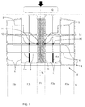
- Figure 2 shows the results of a frontal impact of the vehicle with an obstacle 0.
- At least the driver's seat is supported by a support element S represented by means of an L-shaped outline. It may also be a different shape.
- the support may be a separate element from the seat or an element in one piece with the vehicle seat.
- S reference may be made below to the element "S” referring to both the seat or to the relative support element only, said difference being irrelevant for the purposes of comprehension.
- Said support element is connected to the floor F of the vehicle cab at two points N1 and N2.
- the first point N1 is attached, preferably, to a point of the central longitudinal strip F1, while the second point N2 is fixed to an intermediate strip F2a or F2b.
- the central strip F1 is that of greatest strength in that it projects over the engine compartment of the vehicle, which notoriously is a very stiff part of the vehicle. Therefore, it is advantageous to have as the rigid strip, the central strip F1.
- the lateral strips F3a and F3b are completely irrelevant, so that they could be one with the intermediate strips F2a and F2b, presenting reduced mechanical strengths to frontal impacts.
- the first connection point of the seat support S is connected to one of the lateral strips F3a and F3b, while the second connection point of the seat support S is connected to one of the intermediate strips. This will make it possible to achieve a rotation opposite to that shown in Figure 2 .
- the central strip F1 which is optional, as it can be in one piece with the intermediate strips F1a and F1b with reduced mechanical strengths to frontal impacts.
- intermediate strips F1a and F1b may protrude further forward than the lateral strips F3a and F3b, so as to be the first to suffer the effects of a frontal impact.
- one or more of the longitudinal rods La are fragile in that they have a reduced compressive strength, facilitating the sliding rearwards of the intermediate strips F2a and F2b.
- such longitudinal reduced compressive rods La are placed on an opposite side, i.e. rear, of the floor from the front part of the vehicle cab comprising the floor F.
- One or more of the transversal rods which define the intermediate strips may be made so as to have a reduced flexural strength compared to the remaining similar rods.
- the central strip F1 and/or lateral strips F3a, F3b are strengthened with high-strength steel plates or aluminium.
- Embodiment variants may be made to the non-limiting example described, while remaining within the scope of protection of the present invention, comprising all the equivalent embodiments for a person skilled in the art.
Landscapes
- Engineering & Computer Science (AREA)
- Transportation (AREA)
- Mechanical Engineering (AREA)
- Aviation & Aerospace Engineering (AREA)
- Chemical & Material Sciences (AREA)
- Combustion & Propulsion (AREA)
- Body Structure For Vehicles (AREA)
- Seats For Vehicles (AREA)
Abstract
Description
- The present invention relates to the field of passive safety of industrial or commercial vehicles and in particular refers to an anchoring system for a seat.
- The cabs of industrial and commercial vehicles are geometrically configured so that the driver is very close to the perimeter of said cab, therefore, in the event of frontal impact, the driver is likely to be dramatically involved in the accident.
- Consequently the aim of the present invention is to propose an anchoring system for a seat of an industrial or commercial vehicle which makes it possible to offer better passive protection of the driver and possibly, of a passenger.
- The basic idea of the present invention is to divide the floor of the vehicle cab into longitudinal strips, connected and contiguous to each other, and to increase the longitudinal yielding to frontal impact of a relative industrial or commercial vehicle, of one or more of said longitudinal strips of the cab floor. A strip of reduced stiffness is therefore placed alongside a strip of greater stiffness. These are substantially alternated with respect to a transverse extension of the floor. A first point of a seat is attached to a strip of reduced stiffness, while a second point is attached to a floor strip having a greater longitudinal stiffness. In the event of a frontal impact, the longitudinal strip of reduced stiffness slides back with respect to the adjacent strip of greater stiffness. This causes a rotation of the seat in unison with the rearward movement of the strip of reduced stiffness of the cab floor. This makes it possible to face the occupant of the seat towards the inside or the door of the cab, providing more space for the occupant of the seat: driver and/or passenger.
- The object of the present invention is an anchoring system or a seat of an industrial or commercial vehicle according to
claim 1. - Another object of the present invention is a commercial or industrial vehicle comprising the aforesaid anchoring system.
- The claims describe preferred variants of the invention, forming an integral part of the present description.
- Further purposes and advantages of the present invention will be clear from the detailed description below of an example of embodiment thereof (and of its variants) and the appended drawings provided merely by way of a non-limiting example, wherein:
-
Figure 1 schematically shows the anchoring system of the present invention in a normal condition of use of the vehicle, while -
Figure 2 schematically shows the same anchoring system when subjected to frontal impact of the vehicle. - According to a preferred variant of the present invention, shown in
Figure 1 , the floor F of the vehicle cab of an industrial or commercial vehicle consists of a plurality of longitudinal L and transversal T rods connected by nodes N to form a reticulate structure. Said rods are "longitudinal" or "transverse" according to the vehicle's longitudinal extension axis X. - The floor F of the cab gives a clear idea of the plan view of a vehicle cab.
-
Figure 1 also shows an obstacle 0 distanced from the floor F. - According to the variant of
Figure 1 , a central, longitudinal strip (or portion) F1 is particularly robust and resistant to a collision of the vehicle against an obstacle 0. - To give a better understanding of the division into longitudinal strips of the floor of the vehicle cab, just below
figure 1 a Y axis transverse to the longitudinal axis X is shown, identifying the central strip, the intermediate strips F2a and F2b and the peripheral strips F3a and F3b. - The peripheral strips are entirely optional.
- The floor F also identifies a rear edge R, which during a frontal impact, generally remains unchanged.
- According to the variant of
Figure 1 , the intermediate strips F2a and F2b have decreased mechanical strength, i.e. they tend to deform more easily than the other strips and to slide rearwards in the event of a frontal impact with an obstacle 0. -
Figure 2 shows the results of a frontal impact of the vehicle with an obstacle 0. - According to the present invention at least the driver's seat is supported by a support element S represented by means of an L-shaped outline. It may also be a different shape. The support may be a separate element from the seat or an element in one piece with the vehicle seat. Thus, for convenience, reference may be made below to the element "S" referring to both the seat or to the relative support element only, said difference being irrelevant for the purposes of comprehension.
- Said support element is connected to the floor F of the vehicle cab at two points N1 and N2.
- The first point N1 is attached, preferably, to a point of the central longitudinal strip F1, while the second point N2 is fixed to an intermediate strip F2a or F2b.
- In the event of a frontal impact, as shown in
Figure 2 , the support element S undergoes a rotation due to the yielding of the intermediate strip F2a or F2b to which it is fixed, therefore, the relative seat faces towards the relative cab door, where there is more space. - As shown in the figures it is preferable that the central strip F1 is that of greatest strength in that it projects over the engine compartment of the vehicle, which notoriously is a very stiff part of the vehicle. Therefore, it is advantageous to have as the rigid strip, the central strip F1. According to the variant of
Figure 1 , the lateral strips F3a and F3b are completely irrelevant, so that they could be one with the intermediate strips F2a and F2b, presenting reduced mechanical strengths to frontal impacts. According to a favourite variant not shown, the first connection point of the seat support S is connected to one of the lateral strips F3a and F3b, while the second connection point of the seat support S is connected to one of the intermediate strips. This will make it possible to achieve a rotation opposite to that shown inFigure 2 . - In this case, it is the central strip F1 which is optional, as it can be in one piece with the intermediate strips F1a and F1b with reduced mechanical strengths to frontal impacts.
- While from a certain point of view this variant makes it possible to rotate the seat inwards with even more space, from another point of view it is more difficult to ensure the same stiffness of the lateral strips F3a and F3b and the central strip F1 which, in the event of a frontal impact cooperates with the underlying engine.
- However, the intermediate strips F1a and F1b may protrude further forward than the lateral strips F3a and F3b, so as to be the first to suffer the effects of a frontal impact.
- According to a preferred variant of the invention, when the floor is made using a reticulate structure one or more of the longitudinal rods La are fragile in that they have a reduced compressive strength, facilitating the sliding rearwards of the intermediate strips F2a and F2b. Preferably, such longitudinal reduced compressive rods La are placed on an opposite side, i.e. rear, of the floor from the front part of the vehicle cab comprising the floor F.
- One or more of the transversal rods which define the intermediate strips may be made so as to have a reduced flexural strength compared to the remaining similar rods. Preferably, the central strip F1 and/or lateral strips F3a, F3b are strengthened with high-strength steel plates or aluminium.
- Embodiment variants may be made to the non-limiting example described, while remaining within the scope of protection of the present invention, comprising all the equivalent embodiments for a person skilled in the art.
- From the above description a person skilled in the art may make the object of the invention without introducing any further construction details. The description in the chapter related to the state of the art is merely for a better understanding of the invention and is not a statement of the existence of what is described.
- Furthermore, unless specifically excluded in the detailed description, the contents of the chapter on the state of the art may be considered in combination with the characteristics of the present invention, forming an integral part of the present invention. None of the characteristics of the different variants is essential, except as indicated in the independent claims, therefore, the individual characteristics of each preferred variant or drawing may be individually combined with the other variants described.
In the present description the term "second" component does not imply the presence of a "first" component. These terms are in fact used only for clarity and are not intended as limiting.
Claims (8)
- Anchoring system for a seat (S) of an industrial or commercial vehicle, the vehicle comprising a vehicle cab provided with a related floor (F), the floor being formed by contiguous longitudinal strips having different mechanical strengths to frontal impacts of the vehicle cab, wherein a first strip (F1, F3a, F3b) has a greater mechanical strength, and a second strip (F2a, F2b) has decreased mechanical strength with respect to said first strip, the seat (S) being anchored to the floor (F) in two points (N1, N2), of which a first point is connected to said first strip (F1, F3a, F3b) and a second point (N2) is connected to said second strip (F2a, F2b), so that, in case of frontal impact, said second strip is adapted to slide longitudinally with respect to said first strip causing a rotation of said seat about said first anchor point (N1).
- Anchoring system according to claim 1, wherein said floor (F) is made by means of a reticulate structure formed by longitudinal (L) and transverse (T) rods, with respect to a longitudinal extension of the vehicle (X), mutually connected in respective nodes (N, N1, N2) and wherein said second strip (F2a, F2b), with decreased mechanical strength, comprises one or more rods (La) with decreased compressive strength adapted to facilitate a backward sliding of said second strip.
- System according to claim 2, wherein said rods with decreased compressive strength (La) are positioned at the rear, i.e. in opposite position with respect to a frontal part of the vehicle cab.
- System according to one of claims 2 or 3, wherein one or more of said transverse rods (T) have decreased mechanical bending strength with respect to the remaining transverse rods.
- System according to any one of the preceding claims 1 to 4, wherein said floor (F) has an arrangement of said first and second strips symmetrical with respect to a longitudinal extension axis of the vehicle (X).
- System according to any one of the preceding claims 1 to 5, wherein said first strip (F1) is arranged in medial position with respect to a transverse extension (Y) of the floor (F).
- System according to any one of the preceding claims 1 to 5, wherein said first strip (F3a/F3b) is arranged in lateral position with respect to a transverse extension (Y) of the floor (F).
- Industrial or commercial vehicle comprising a vehicle cab provided with a related floor (F) and provided with an anchoring system for a seat (S) according to any one of claims 1 to 7.
Applications Claiming Priority (1)
| Application Number | Priority Date | Filing Date | Title |
|---|---|---|---|
| ITTO20141051 | 2014-12-16 |
Publications (2)
| Publication Number | Publication Date |
|---|---|
| EP3034381A1 true EP3034381A1 (en) | 2016-06-22 |
| EP3034381B1 EP3034381B1 (en) | 2017-11-15 |
Family
ID=52444576
Family Applications (1)
| Application Number | Title | Priority Date | Filing Date |
|---|---|---|---|
| EP15200595.5A Active EP3034381B1 (en) | 2014-12-16 | 2015-12-16 | Anchoring system for a seat of an industrial or commercial vehicle |
Country Status (2)
| Country | Link |
|---|---|
| EP (1) | EP3034381B1 (en) |
| ES (1) | ES2659416T3 (en) |
Citations (5)
| Publication number | Priority date | Publication date | Assignee | Title |
|---|---|---|---|---|
| DE69400180T2 (en) * | 1993-03-16 | 1996-10-02 | Matra Automobile | Vehicle housing structure with seat anchoring device |
| US6182411B1 (en) * | 1998-02-10 | 2001-02-06 | Lear Corporation | Structural component for vehicle flooring |
| US20030137163A1 (en) * | 2002-01-23 | 2003-07-24 | Honda Giken Kogyo Kabushiki Kaisha | Vehicle floor structure |
| DE102009048335A1 (en) * | 2009-10-06 | 2011-04-07 | GM Global Technology Operations, Inc., Detroit | Seat cross beam for fastening seat to body undersurface of motor vehicle, has longitudinal profiles provided with ramp shaped connecting sections that are connected with transverse profile |
| DE102010021087A1 (en) * | 2010-05-19 | 2011-11-24 | Gm Global Technology Operations Llc (N.D.Ges.D. Staates Delaware) | Body structure for motor vehicle i.e. passenger motor vehicle, has front and rear seat attachments arranged at floor structure of motor vehicle, where rear seat attachment is constantly formed and defined at left and right side skills |
-
2015
- 2015-12-16 EP EP15200595.5A patent/EP3034381B1/en active Active
- 2015-12-16 ES ES15200595.5T patent/ES2659416T3/en active Active
Patent Citations (5)
| Publication number | Priority date | Publication date | Assignee | Title |
|---|---|---|---|---|
| DE69400180T2 (en) * | 1993-03-16 | 1996-10-02 | Matra Automobile | Vehicle housing structure with seat anchoring device |
| US6182411B1 (en) * | 1998-02-10 | 2001-02-06 | Lear Corporation | Structural component for vehicle flooring |
| US20030137163A1 (en) * | 2002-01-23 | 2003-07-24 | Honda Giken Kogyo Kabushiki Kaisha | Vehicle floor structure |
| DE102009048335A1 (en) * | 2009-10-06 | 2011-04-07 | GM Global Technology Operations, Inc., Detroit | Seat cross beam for fastening seat to body undersurface of motor vehicle, has longitudinal profiles provided with ramp shaped connecting sections that are connected with transverse profile |
| DE102010021087A1 (en) * | 2010-05-19 | 2011-11-24 | Gm Global Technology Operations Llc (N.D.Ges.D. Staates Delaware) | Body structure for motor vehicle i.e. passenger motor vehicle, has front and rear seat attachments arranged at floor structure of motor vehicle, where rear seat attachment is constantly formed and defined at left and right side skills |
Also Published As
| Publication number | Publication date |
|---|---|
| ES2659416T3 (en) | 2018-03-15 |
| EP3034381B1 (en) | 2017-11-15 |
Similar Documents
| Publication | Publication Date | Title |
|---|---|---|
| JP6478031B2 (en) | Underbody skeleton structure | |
| JP6254872B2 (en) | Body frame structure | |
| EP2639142B1 (en) | Front hood structure for vehicle | |
| US9446795B2 (en) | Structure for reinforcing front vehicle body | |
| JP6860567B2 (en) | Vehicle undercarriage with transverse beam with varying resistance to plastic deformation | |
| CN105620400A (en) | Bumpers including energy diverting bumper structures and vehicles incorporating the same | |
| US10745058B2 (en) | Upper arch structure of vehicle body lateral section | |
| CN105383568A (en) | Vehicle Center Pillar | |
| JP6439401B2 (en) | Side sill reinforcement structure | |
| EP3034381B1 (en) | Anchoring system for a seat of an industrial or commercial vehicle | |
| US20220105887A1 (en) | Member for ratcheting between a moving component and adjacent structure | |
| CN104044646B (en) | Structure of rear vehicle | |
| JP2018176771A5 (en) | ||
| EP2915725B1 (en) | Cab reinforcing structure | |
| JP2016052820A (en) | Rear seat back frame structure | |
| US10106198B2 (en) | Vehicle upper body structure | |
| US20130221697A1 (en) | Multi-functional cargo retention net | |
| CN105459940B (en) | Vehicle rear constructs | |
| CN102529774B (en) | The frame structure of back of seat | |
| JP6432724B2 (en) | Seat belt mounting bracket | |
| ES2902534T3 (en) | Utility vehicle comprising a partition wall | |
| US20170341614A1 (en) | Utility vehicle | |
| CN103171633B (en) | Rear car body structure | |
| CN205706906U (en) | Floor after a kind of vehicle body | |
| JP6757153B2 (en) | Crew protection structure in the event of a side collision of the vehicle |
Legal Events
| Date | Code | Title | Description |
|---|---|---|---|
| PUAI | Public reference made under article 153(3) epc to a published international application that has entered the european phase |
Free format text: ORIGINAL CODE: 0009012 |
|
| AK | Designated contracting states |
Kind code of ref document: A1 Designated state(s): AL AT BE BG CH CY CZ DE DK EE ES FI FR GB GR HR HU IE IS IT LI LT LU LV MC MK MT NL NO PL PT RO RS SE SI SK SM TR |
|
| AX | Request for extension of the european patent |
Extension state: BA ME |
|
| 17P | Request for examination filed |
Effective date: 20161221 |
|
| RBV | Designated contracting states (corrected) |
Designated state(s): AL AT BE BG CH CY CZ DE DK EE ES FI FR GB GR HR HU IE IS IT LI LT LU LV MC MK MT NL NO PL PT RO RS SE SI SK SM TR |
|
| GRAP | Despatch of communication of intention to grant a patent |
Free format text: ORIGINAL CODE: EPIDOSNIGR1 |
|
| RIC1 | Information provided on ipc code assigned before grant |
Ipc: B62D 25/20 20060101AFI20170524BHEP Ipc: B62D 21/15 20060101ALI20170524BHEP Ipc: B60N 2/015 20060101ALI20170524BHEP Ipc: B60N 2/42 20060101ALI20170524BHEP Ipc: B62D 33/06 20060101ALI20170524BHEP |
|
| INTG | Intention to grant announced |
Effective date: 20170613 |
|
| GRAS | Grant fee paid |
Free format text: ORIGINAL CODE: EPIDOSNIGR3 |
|
| GRAA | (expected) grant |
Free format text: ORIGINAL CODE: 0009210 |
|
| AK | Designated contracting states |
Kind code of ref document: B1 Designated state(s): AL AT BE BG CH CY CZ DE DK EE ES FI FR GB GR HR HU IE IS IT LI LT LU LV MC MK MT NL NO PL PT RO RS SE SI SK SM TR |
|
| REG | Reference to a national code |
Ref country code: CH Ref legal event code: EP Ref country code: GB Ref legal event code: FG4D Ref country code: AT Ref legal event code: REF Ref document number: 945971 Country of ref document: AT Kind code of ref document: T Effective date: 20171115 |
|
| REG | Reference to a national code |
Ref country code: IE Ref legal event code: FG4D |
|
| REG | Reference to a national code |
Ref country code: DE Ref legal event code: R096 Ref document number: 602015006009 Country of ref document: DE |
|
| REG | Reference to a national code |
Ref country code: FR Ref legal event code: PLFP Year of fee payment: 3 |
|
| REG | Reference to a national code |
Ref country code: SE Ref legal event code: TRGR |
|
| REG | Reference to a national code |
Ref country code: NL Ref legal event code: FP |
|
| REG | Reference to a national code |
Ref country code: ES Ref legal event code: FG2A Ref document number: 2659416 Country of ref document: ES Kind code of ref document: T3 Effective date: 20180315 |
|
| REG | Reference to a national code |
Ref country code: LT Ref legal event code: MG4D |
|
| REG | Reference to a national code |
Ref country code: AT Ref legal event code: MK05 Ref document number: 945971 Country of ref document: AT Kind code of ref document: T Effective date: 20171115 |
|
| PG25 | Lapsed in a contracting state [announced via postgrant information from national office to epo] |
Ref country code: NO Free format text: LAPSE BECAUSE OF FAILURE TO SUBMIT A TRANSLATION OF THE DESCRIPTION OR TO PAY THE FEE WITHIN THE PRESCRIBED TIME-LIMIT Effective date: 20180215 Ref country code: FI Free format text: LAPSE BECAUSE OF FAILURE TO SUBMIT A TRANSLATION OF THE DESCRIPTION OR TO PAY THE FEE WITHIN THE PRESCRIBED TIME-LIMIT Effective date: 20171115 Ref country code: LT Free format text: LAPSE BECAUSE OF FAILURE TO SUBMIT A TRANSLATION OF THE DESCRIPTION OR TO PAY THE FEE WITHIN THE PRESCRIBED TIME-LIMIT Effective date: 20171115 |
|
| PG25 | Lapsed in a contracting state [announced via postgrant information from national office to epo] |
Ref country code: AT Free format text: LAPSE BECAUSE OF FAILURE TO SUBMIT A TRANSLATION OF THE DESCRIPTION OR TO PAY THE FEE WITHIN THE PRESCRIBED TIME-LIMIT Effective date: 20171115 Ref country code: LV Free format text: LAPSE BECAUSE OF FAILURE TO SUBMIT A TRANSLATION OF THE DESCRIPTION OR TO PAY THE FEE WITHIN THE PRESCRIBED TIME-LIMIT Effective date: 20171115 Ref country code: HR Free format text: LAPSE BECAUSE OF FAILURE TO SUBMIT A TRANSLATION OF THE DESCRIPTION OR TO PAY THE FEE WITHIN THE PRESCRIBED TIME-LIMIT Effective date: 20171115 Ref country code: RS Free format text: LAPSE BECAUSE OF FAILURE TO SUBMIT A TRANSLATION OF THE DESCRIPTION OR TO PAY THE FEE WITHIN THE PRESCRIBED TIME-LIMIT Effective date: 20171115 Ref country code: GR Free format text: LAPSE BECAUSE OF FAILURE TO SUBMIT A TRANSLATION OF THE DESCRIPTION OR TO PAY THE FEE WITHIN THE PRESCRIBED TIME-LIMIT Effective date: 20180216 Ref country code: BG Free format text: LAPSE BECAUSE OF FAILURE TO SUBMIT A TRANSLATION OF THE DESCRIPTION OR TO PAY THE FEE WITHIN THE PRESCRIBED TIME-LIMIT Effective date: 20180215 |
|
| PG25 | Lapsed in a contracting state [announced via postgrant information from national office to epo] |
Ref country code: CY Free format text: LAPSE BECAUSE OF FAILURE TO SUBMIT A TRANSLATION OF THE DESCRIPTION OR TO PAY THE FEE WITHIN THE PRESCRIBED TIME-LIMIT Effective date: 20171115 Ref country code: CZ Free format text: LAPSE BECAUSE OF FAILURE TO SUBMIT A TRANSLATION OF THE DESCRIPTION OR TO PAY THE FEE WITHIN THE PRESCRIBED TIME-LIMIT Effective date: 20171115 Ref country code: SK Free format text: LAPSE BECAUSE OF FAILURE TO SUBMIT A TRANSLATION OF THE DESCRIPTION OR TO PAY THE FEE WITHIN THE PRESCRIBED TIME-LIMIT Effective date: 20171115 Ref country code: EE Free format text: LAPSE BECAUSE OF FAILURE TO SUBMIT A TRANSLATION OF THE DESCRIPTION OR TO PAY THE FEE WITHIN THE PRESCRIBED TIME-LIMIT Effective date: 20171115 Ref country code: DK Free format text: LAPSE BECAUSE OF FAILURE TO SUBMIT A TRANSLATION OF THE DESCRIPTION OR TO PAY THE FEE WITHIN THE PRESCRIBED TIME-LIMIT Effective date: 20171115 |
|
| REG | Reference to a national code |
Ref country code: DE Ref legal event code: R097 Ref document number: 602015006009 Country of ref document: DE |
|
| PG25 | Lapsed in a contracting state [announced via postgrant information from national office to epo] |
Ref country code: RO Free format text: LAPSE BECAUSE OF FAILURE TO SUBMIT A TRANSLATION OF THE DESCRIPTION OR TO PAY THE FEE WITHIN THE PRESCRIBED TIME-LIMIT Effective date: 20171115 Ref country code: PL Free format text: LAPSE BECAUSE OF FAILURE TO SUBMIT A TRANSLATION OF THE DESCRIPTION OR TO PAY THE FEE WITHIN THE PRESCRIBED TIME-LIMIT Effective date: 20171115 Ref country code: SM Free format text: LAPSE BECAUSE OF FAILURE TO SUBMIT A TRANSLATION OF THE DESCRIPTION OR TO PAY THE FEE WITHIN THE PRESCRIBED TIME-LIMIT Effective date: 20171115 |
|
| REG | Reference to a national code |
Ref country code: IE Ref legal event code: MM4A |
|
| PLBE | No opposition filed within time limit |
Free format text: ORIGINAL CODE: 0009261 |
|
| STAA | Information on the status of an ep patent application or granted ep patent |
Free format text: STATUS: NO OPPOSITION FILED WITHIN TIME LIMIT |
|
| PG25 | Lapsed in a contracting state [announced via postgrant information from national office to epo] |
Ref country code: LU Free format text: LAPSE BECAUSE OF NON-PAYMENT OF DUE FEES Effective date: 20171216 Ref country code: MT Free format text: LAPSE BECAUSE OF NON-PAYMENT OF DUE FEES Effective date: 20171216 |
|
| REG | Reference to a national code |
Ref country code: BE Ref legal event code: MM Effective date: 20171231 |
|
| 26N | No opposition filed |
Effective date: 20180817 |
|
| PG25 | Lapsed in a contracting state [announced via postgrant information from national office to epo] |
Ref country code: IE Free format text: LAPSE BECAUSE OF NON-PAYMENT OF DUE FEES Effective date: 20171216 |
|
| PG25 | Lapsed in a contracting state [announced via postgrant information from national office to epo] |
Ref country code: SI Free format text: LAPSE BECAUSE OF FAILURE TO SUBMIT A TRANSLATION OF THE DESCRIPTION OR TO PAY THE FEE WITHIN THE PRESCRIBED TIME-LIMIT Effective date: 20171115 Ref country code: BE Free format text: LAPSE BECAUSE OF NON-PAYMENT OF DUE FEES Effective date: 20171231 |
|
| PG25 | Lapsed in a contracting state [announced via postgrant information from national office to epo] |
Ref country code: HU Free format text: LAPSE BECAUSE OF FAILURE TO SUBMIT A TRANSLATION OF THE DESCRIPTION OR TO PAY THE FEE WITHIN THE PRESCRIBED TIME-LIMIT; INVALID AB INITIO Effective date: 20151216 Ref country code: MC Free format text: LAPSE BECAUSE OF FAILURE TO SUBMIT A TRANSLATION OF THE DESCRIPTION OR TO PAY THE FEE WITHIN THE PRESCRIBED TIME-LIMIT Effective date: 20171115 |
|
| REG | Reference to a national code |
Ref country code: CH Ref legal event code: PL |
|
| PG25 | Lapsed in a contracting state [announced via postgrant information from national office to epo] |
Ref country code: MK Free format text: LAPSE BECAUSE OF FAILURE TO SUBMIT A TRANSLATION OF THE DESCRIPTION OR TO PAY THE FEE WITHIN THE PRESCRIBED TIME-LIMIT Effective date: 20171115 |
|
| PG25 | Lapsed in a contracting state [announced via postgrant information from national office to epo] |
Ref country code: CH Free format text: LAPSE BECAUSE OF NON-PAYMENT OF DUE FEES Effective date: 20181231 Ref country code: LI Free format text: LAPSE BECAUSE OF NON-PAYMENT OF DUE FEES Effective date: 20181231 |
|
| PG25 | Lapsed in a contracting state [announced via postgrant information from national office to epo] |
Ref country code: TR Free format text: LAPSE BECAUSE OF FAILURE TO SUBMIT A TRANSLATION OF THE DESCRIPTION OR TO PAY THE FEE WITHIN THE PRESCRIBED TIME-LIMIT Effective date: 20171115 |
|
| PG25 | Lapsed in a contracting state [announced via postgrant information from national office to epo] |
Ref country code: PT Free format text: LAPSE BECAUSE OF FAILURE TO SUBMIT A TRANSLATION OF THE DESCRIPTION OR TO PAY THE FEE WITHIN THE PRESCRIBED TIME-LIMIT Effective date: 20171115 |
|
| PG25 | Lapsed in a contracting state [announced via postgrant information from national office to epo] |
Ref country code: AL Free format text: LAPSE BECAUSE OF FAILURE TO SUBMIT A TRANSLATION OF THE DESCRIPTION OR TO PAY THE FEE WITHIN THE PRESCRIBED TIME-LIMIT Effective date: 20171115 Ref country code: IS Free format text: LAPSE BECAUSE OF FAILURE TO SUBMIT A TRANSLATION OF THE DESCRIPTION OR TO PAY THE FEE WITHIN THE PRESCRIBED TIME-LIMIT Effective date: 20180315 |
|
| P01 | Opt-out of the competence of the unified patent court (upc) registered |
Effective date: 20230523 |
|
| PGFP | Annual fee paid to national office [announced via postgrant information from national office to epo] |
Ref country code: GB Payment date: 20251223 Year of fee payment: 11 |
|
| PGFP | Annual fee paid to national office [announced via postgrant information from national office to epo] |
Ref country code: IT Payment date: 20251120 Year of fee payment: 11 |
|
| PGFP | Annual fee paid to national office [announced via postgrant information from national office to epo] |
Ref country code: NL Payment date: 20251222 Year of fee payment: 11 Ref country code: FR Payment date: 20251223 Year of fee payment: 11 |
|
| PGFP | Annual fee paid to national office [announced via postgrant information from national office to epo] |
Ref country code: SE Payment date: 20251222 Year of fee payment: 11 |
|
| PGFP | Annual fee paid to national office [announced via postgrant information from national office to epo] |
Ref country code: ES Payment date: 20260122 Year of fee payment: 11 |
|
| PGFP | Annual fee paid to national office [announced via postgrant information from national office to epo] |
Ref country code: DE Payment date: 20251229 Year of fee payment: 11 |