EP3034357A1 - Tool carrier platform for self-propelled vehicles and self-propelled vehicle including it - Google Patents
Tool carrier platform for self-propelled vehicles and self-propelled vehicle including it Download PDFInfo
- Publication number
- EP3034357A1 EP3034357A1 EP14198545.7A EP14198545A EP3034357A1 EP 3034357 A1 EP3034357 A1 EP 3034357A1 EP 14198545 A EP14198545 A EP 14198545A EP 3034357 A1 EP3034357 A1 EP 3034357A1
- Authority
- EP
- European Patent Office
- Prior art keywords
- self
- propelled vehicle
- locking holes
- plate
- locking
- Prior art date
- Legal status (The legal status is an assumption and is not a legal conclusion. Google has not performed a legal analysis and makes no representation as to the accuracy of the status listed.)
- Granted
Links
Images


Classifications
-
- B—PERFORMING OPERATIONS; TRANSPORTING
- B60—VEHICLES IN GENERAL
- B60P—VEHICLES ADAPTED FOR LOAD TRANSPORTATION OR TO TRANSPORT, TO CARRY, OR TO COMPRISE SPECIAL LOADS OR OBJECTS
- B60P3/00—Vehicles adapted to transport, to carry or to comprise special loads or objects
- B60P3/42—Vehicles adapted to transport, to carry or to comprise special loads or objects convertible from one use to a different one
Definitions
- the present invention has as subject a tool-carrying platform, apt to be used on the floor of a self-propelled vehicle, for assembling tools, and a self-propelled vehicle using it.
- One of the main requirements upon using self-propelled vehicles, in particular in the field of construction sites, is to be able to have available flexibility as much as possible.
- Self-propelled vehicles in particular of the type with small sizes, can be used both to assemble caissons, tilting caissons and other containers for transporting objects, liquids and so on, and to constitute the platform of the most different tools, such crane arms with different shapes.
- the technical problem underlying the present invention is to provide a self-propelled vehicle equipped with a tool-carrying platform allowing to obviate the drawback mentioned by referring to the known art.
- the main advantage of the self-propelled vehicle according to the present invention lies in the fact of allowing a quick assembly of a platform able to allow to assemble many tools.
- a tool-carrying platform is designated as a whole with 1. It is constituted by a sliding plate with rectangular shape, equipped at the centre with an opening 2 for assembling (not represented) tools.
- the opening 2 is arranged at the centre in a depressed area of the plate.
- the sliding plate comprises respective guides 3 with grooves facing downwards.
- the plate at its ends has a front side, which is apt to be positioned on the front portion of a self-propelled vehicle forming an access side of the plate, and a rear side.
- the guides 3 On the front side the guides 3 have respective first locking holes 4, aligned therebetween.
- the plate comprises a back 5 apt to be rested against the rear portion of a self-propelled vehicle; at the sides of the back 5, the plate 1 comprises respective second locking holes 6, directed with their axis perpendicularly to the back 5.
- a self-propelled vehicle 7 comprises a frame, a (not visible) engine, a front access side and a rear side wherein the (not represented) guiding position is formed.
- the frame is equipped with tracks 8 extending longitudinally withe respect to the vehicle 7.
- the frame comprises a pair of longitudinal rails 9 extending between the front and rear sides. They are complementary to the grooves of the above-mentioned guides 3 which, altogether, implement respective sliding guides of the plate 1.
- the frame of the vehicle 7 comprises projecting pins 10 positioned so as to be able to insert into said second locking holes 6.
- the rails 9 end with respective hooks 11 which, after having finished to insert the plate 1, correspond to said first locking holes 4.
- the rails at the front end thereof, comprise further third locking holes 12.
- the vehicle 7 comprises a locking device 13 ( figure 3 ) comprising a pair of cross arms 14 separated by a central lever 15, perpendicular thereto.
- the arms 14 can be detached and engage the lever 15 at one seat thereof 16 aligning them.
- the fastening between seat 16 and arms 14 is completed by means of inserting elastic plugs 17 in suitable holes.
- Each arm has a distal end comprising locking small arms 19 perpendicular to the arms 14, comprising respective fourth locking holes 18.
- fifth locking holes 20 On the guides 3 of the plate 1 there are even fifth locking holes 20 at the front side. As it can be seen, third, fourth and fifth locking holes 12, 18, 20 are destined to align therebetween upon locking.
- the plate 1 On the rear side, at last, the plate 1 comprises a registration pin 21 on each side, inserted into a respective registration seat 22 and equipped with a ring nut 23 ( figure 4 ).
- the vehicle 7 ( figure 6A ), properly positioned, and the plate 1 ( figure 6B ) are aligned therebetween so that the grooves faced downwards of the plate 7 are in line with the rails 9 of the vehicle 7. Then, the plate 1 is made to slide on the frame of the vehicle 7 until the back 5 rests on the rear side of the vehicle 7, that is on the guiding position thereof.
- the arms 14 are inserted through the first locking holes 14 and the hooks 11 and are joined in the seat 16 of the lever 15 ( figures 1A and 2 ), then locked with the elastic plugs 17.
Landscapes
- Engineering & Computer Science (AREA)
- Health & Medical Sciences (AREA)
- Public Health (AREA)
- Transportation (AREA)
- Mechanical Engineering (AREA)
- Connection Of Plates (AREA)
- Automobile Manufacture Line, Endless Track Vehicle, Trailer (AREA)
Abstract
Description
- The present invention has as subject a tool-carrying platform, apt to be used on the floor of a self-propelled vehicle, for assembling tools, and a self-propelled vehicle using it.
- One of the main requirements upon using self-propelled vehicles, in particular in the field of construction sites, is to be able to have available flexibility as much as possible.
- Self-propelled vehicles, in particular of the type with small sizes, can be used both to assemble caissons, tilting caissons and other containers for transporting objects, liquids and so on, and to constitute the platform of the most different tools, such crane arms with different shapes.
- On this matter, on the self-propelled vehicle it should be possible to assemble such tools in a quick and safe way, with the minimum number of mechanical procedures.
- However, the known solutions do not meet the above-mentioned flexibility, safety and quickness requirements.
- The technical problem underlying the present invention is to provide a self-propelled vehicle equipped with a tool-carrying platform allowing to obviate the drawback mentioned by referring to the known art.
- Such problem is solved by a self-propelled vehicle as specified above characterizing in the fact of comprising:
- a pair of horizontal guides extending longitudinally with respect to the floor of the vehicle, wherein an end is arranged at an assembling side;
- a sliding plate, apt to slide on said guides, provided with front and rear locking holes;
- means for locking the plate sliding on the frame of the self-propelled vehicle, acting on said front and rear locking holes; and
- registering means, able to eliminate the residual backlash between the plate and the frame, forming a tool-carrying platform.
- The main advantage of the self-propelled vehicle according to the present invention lies in the fact of allowing a quick assembly of a platform able to allow to assemble many tools.
- The present invention will be described hereinafter according to a preferred embodiment example thereof provided by way of example and not for limitative purpose with reference to the enclosed drawings wherein:
-
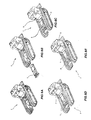
figures 1A and 1B show respective axonometric views of a tool-carrying platform according to the invention in two different assembly configurations; -
figure 2 illustrates different phases for assembling the tool-carrying platform offigure 1 on a self-propelled vehicle properly modified according to the invention; -
figure 3 shows some assembling complements of the tool-carrying platform offigure 1 on a self-propelled vehicle; -
figure 4 shows a detail of the self-propelled vehicle offigure 2 ; -
figure 5 shows an enlarged axonometric view of the self-propelled vehicle offigure 1 ; and -
figures 6A, 6B, 6C, 6D e6E show different phases for assembling the tool-carrying platform offigure 1 . - With reference to the figures, a tool-carrying platform is designated as a whole with 1. It is constituted by a sliding plate with rectangular shape, equipped at the centre with an
opening 2 for assembling (not represented) tools. - The
opening 2 is arranged at the centre in a depressed area of the plate. At the longitudinal edges thereof, the sliding plate comprises respective guides 3 with grooves facing downwards. - The plate at its ends has a front side, which is apt to be positioned on the front portion of a self-propelled vehicle forming an access side of the plate, and a rear side. On the front side the guides 3 have respective first locking holes 4, aligned therebetween.
- At the rear side, the plate comprises a
back 5 apt to be rested against the rear portion of a self-propelled vehicle; at the sides of theback 5, the plate 1 comprises respectivesecond locking holes 6, directed with their axis perpendicularly to theback 5. - By referring to
figure 2 , a self-propelledvehicle 7 comprises a frame, a (not visible) engine, a front access side and a rear side wherein the (not represented) guiding position is formed. The frame is equipped withtracks 8 extending longitudinally withe respect to thevehicle 7. - The frame comprises a pair of
longitudinal rails 9 extending between the front and rear sides. They are complementary to the grooves of the above-mentioned guides 3 which, altogether, implement respective sliding guides of the plate 1. - At the rear side, the frame of the
vehicle 7 comprises projectingpins 10 positioned so as to be able to insert into saidsecond locking holes 6. - At the access side, the
rails 9 end withrespective hooks 11 which, after having finished to insert the plate 1, correspond to said first locking holes 4. - Furthermore, the rails, at the front end thereof, comprise further
third locking holes 12. - At last, the
vehicle 7 comprises a locking device 13 (figure 3 ) comprising a pair ofcross arms 14 separated by acentral lever 15, perpendicular thereto. - The
arms 14 can be detached and engage thelever 15 at one seat thereof 16 aligning them. The fastening betweenseat 16 andarms 14 is completed by means of insertingelastic plugs 17 in suitable holes. - Each arm has a distal end comprising locking
small arms 19 perpendicular to thearms 14, comprising respectivefourth locking holes 18. - On the guides 3 of the plate 1 there are even
fifth locking holes 20 at the front side. As it can be seen, third, fourth andfifth locking holes - On the rear side, at last, the plate 1 comprises a
registration pin 21 on each side, inserted into arespective registration seat 22 and equipped with a ring nut 23 (figure 4 ). - By referring to
figures 6A to 6E , the vehicle 7 (figure 6A ), properly positioned, and the plate 1 (figure 6B ) are aligned therebetween so that the grooves faced downwards of theplate 7 are in line with therails 9 of thevehicle 7. Then, the plate 1 is made to slide on the frame of thevehicle 7 until theback 5 rests on the rear side of thevehicle 7, that is on the guiding position thereof. - In this position (
figure 6D ), thepins 10 engage thesecond locking holes 6. - Furthermore, the
arms 14 are inserted through thefirst locking holes 14 and thehooks 11 and are joined in theseat 16 of the lever 15 (figures 1A and2 ), then locked with theelastic plugs 17. - At this point (
figure 6E ), thelever 15 is rotated by 90° by bringing said third, fourth andfifth locking holes figure 2 ). - At last, the residual backlashes between plate 1 and frame are eliminated by acting on the
ring nuts 23 adjusting the position ofregistration pin 21 on the frame. - To the above-described self-propelled vehicle with tool-carrying platform a person skilled in the art, in order to satisfy additional and contingent needs, can introduce several additional modifications and variants, all however within the protective scope of the present invention, as defined by the enclosed claims.
Claims (8)
- A self-propelled vehicle (7) provided with a tool-carrying platform, characterized in that it comprises:• a pair of horizontal guides (3, 9) extending longitudinally with respect to the floor of the self-propelled vehicle (7), wherein an end is arranged at an access side;• a sliding plate (1), apt to slide on said guides (3, 9) equipped with front (4, 20) and rear (6) locking holes;• means for locking the plate sliding on the frame of the self-propelled vehicle (7), acting on said front (4, 20) and rear (6) locking holes; and• registration means (21, 22, 23), able to eliminate the residual backlash between the plate (1) and the frame, by forming a tool-carrying platform.
- The self-propelled vehicle (7) according to claim 1, wherein said horizontal guides are formed by grooves at the longitudinal edges of the sliding plate (1) and by corresponding rails (9) of the frame of the self-propelled vehicle (7)
- The self-propelled vehicle (7) according to claim 1, wherein the rear locking holes (6) are engaged by respective projecting pins (10) of the frame, positioned so as to be able to insert into said second locking holes (6).
- The self-propelled vehicle (7) according to claim 2, wherein said front holes (4) are destined to be aligned with respective hooks (11) on the front ends of said rails (9).
- The self-propelled vehicle (7) according to claim 4, wherein said rails (9), at the front end thereof, comprises additional locking holes (12).
- The self-propelled vehicle (7) according to claim 5, comprising a locking device (13) having a pair of cross arms (14) which can be detached and they are separated by a central lever (15), perpendicular thereto.
- The self-propelled vehicle (7) according to claim 6, wherein the arms (14) have a distal end comprising locking small arms (19) perpendicular to the arms (14), comprising respective locking holes (18) apt to be aligned, by means of rotating said lever (15), with the locking holes (12, 20) of the rails (9) and of the guides (3) of the plate (1).
- The self-propelled vehicle (7) according to claim 1, wherein the plate (1) comprises a registration pin (21) on each side, inserted in a respective registration seat (22) and equipped with a ring nut (23).
Priority Applications (1)
| Application Number | Priority Date | Filing Date | Title |
|---|---|---|---|
| EP14198545.7A EP3034357B1 (en) | 2014-12-17 | 2014-12-17 | Tool carrier platform for self-propelled vehicles and self-propelled vehicle including it |
Applications Claiming Priority (1)
| Application Number | Priority Date | Filing Date | Title |
|---|---|---|---|
| EP14198545.7A EP3034357B1 (en) | 2014-12-17 | 2014-12-17 | Tool carrier platform for self-propelled vehicles and self-propelled vehicle including it |
Publications (2)
| Publication Number | Publication Date |
|---|---|
| EP3034357A1 true EP3034357A1 (en) | 2016-06-22 |
| EP3034357B1 EP3034357B1 (en) | 2019-11-27 |
Family
ID=52469566
Family Applications (1)
| Application Number | Title | Priority Date | Filing Date |
|---|---|---|---|
| EP14198545.7A Active EP3034357B1 (en) | 2014-12-17 | 2014-12-17 | Tool carrier platform for self-propelled vehicles and self-propelled vehicle including it |
Country Status (1)
| Country | Link |
|---|---|
| EP (1) | EP3034357B1 (en) |
Citations (4)
| Publication number | Priority date | Publication date | Assignee | Title |
|---|---|---|---|---|
| US5573300A (en) * | 1994-12-19 | 1996-11-12 | Simmons; Michael C. | Utility vehicles with interchangeable emergency response modules |
| US20050196261A1 (en) * | 2004-02-19 | 2005-09-08 | Green Kevin J. | Utility vehicle |
| EP2080730A1 (en) * | 2007-10-24 | 2009-07-22 | Cormidi S.r.l. | Self-propelled industrial vehicle |
| FR2926758A1 (en) * | 2008-01-29 | 2009-07-31 | Repentance Dev Sarl | Loading arrangement for e.g. trailer in military application, has sliding unit distinct from maintaining unit that maintains base and subframe to be inseparable during their sliding, where maintaining unit is distinct from locking unit |
-
2014
- 2014-12-17 EP EP14198545.7A patent/EP3034357B1/en active Active
Patent Citations (4)
| Publication number | Priority date | Publication date | Assignee | Title |
|---|---|---|---|---|
| US5573300A (en) * | 1994-12-19 | 1996-11-12 | Simmons; Michael C. | Utility vehicles with interchangeable emergency response modules |
| US20050196261A1 (en) * | 2004-02-19 | 2005-09-08 | Green Kevin J. | Utility vehicle |
| EP2080730A1 (en) * | 2007-10-24 | 2009-07-22 | Cormidi S.r.l. | Self-propelled industrial vehicle |
| FR2926758A1 (en) * | 2008-01-29 | 2009-07-31 | Repentance Dev Sarl | Loading arrangement for e.g. trailer in military application, has sliding unit distinct from maintaining unit that maintains base and subframe to be inseparable during their sliding, where maintaining unit is distinct from locking unit |
Also Published As
| Publication number | Publication date |
|---|---|
| EP3034357B1 (en) | 2019-11-27 |
Similar Documents
| Publication | Publication Date | Title |
|---|---|---|
| USD867582S1 (en) | Syringe device | |
| USD869309S1 (en) | Diagnostic analyzer | |
| US10253912B2 (en) | Multi-coupling device for the multiple quick coupling of multiple hydraulic, electrical and/or pneumatic lines, with the possibility of individual manual couplings | |
| ES2543165T3 (en) | Compact seating arrangement | |
| USD875965S1 (en) | Ovulation test device | |
| USD810693S1 (en) | Connector terminals (P04-2P-3P-5P) | |
| USD857570S1 (en) | Front bumper for motor vehicle | |
| USD827318S1 (en) | Vehicle seat | |
| WO2012042546A8 (en) | Modular structure for supporting blanks | |
| US20190269477A1 (en) | Holding device for holding a portable medical appliance | |
| CN105313728A (en) | child seat | |
| USD912779S1 (en) | Valve | |
| EP3034357A1 (en) | Tool carrier platform for self-propelled vehicles and self-propelled vehicle including it | |
| USD992033S1 (en) | Two-part quick release device for electronic game steering wheels | |
| FR3045707B1 (en) | CONNECTOR FOR ASSEMBLING TWO ROUND COLUMNS WITH EXTERNAL LOCKING RING AND REMOVABLE PINS | |
| CN102873698B (en) | Dermatotome blade assembly | |
| FR3089778B1 (en) | BREATHING MACHINE | |
| AU2020206600B2 (en) | Seating furniture chassis | |
| US20180257247A1 (en) | Switch structure for pliers | |
| EP2527193A1 (en) | Seat slide locking apparatus | |
| USD878940S1 (en) | Laser measuring device | |
| USD777466S1 (en) | Lifting device | |
| MY201920A (en) | Connector for assembling two riser sections with internal locking ring | |
| US20160176355A1 (en) | Instrument panel substrate with pin positioning pattern for correct placement of multiple ecu attachments | |
| US20160325663A1 (en) | Grip mounting structure for utility vehicle, utility vehicle with the same, and grip |
Legal Events
| Date | Code | Title | Description |
|---|---|---|---|
| PUAI | Public reference made under article 153(3) epc to a published international application that has entered the european phase |
Free format text: ORIGINAL CODE: 0009012 |
|
| AK | Designated contracting states |
Kind code of ref document: A1 Designated state(s): AL AT BE BG CH CY CZ DE DK EE ES FI FR GB GR HR HU IE IS IT LI LT LU LV MC MK MT NL NO PL PT RO RS SE SI SK SM TR |
|
| AX | Request for extension of the european patent |
Extension state: BA ME |
|
| STAA | Information on the status of an ep patent application or granted ep patent |
Free format text: STATUS: REQUEST FOR EXAMINATION WAS MADE |
|
| 17P | Request for examination filed |
Effective date: 20161222 |
|
| RBV | Designated contracting states (corrected) |
Designated state(s): AL AT BE BG CH CY CZ DE DK EE ES FI FR GB GR HR HU IE IS IT LI LT LU LV MC MK MT NL NO PL PT RO RS SE SI SK SM TR |
|
| STAA | Information on the status of an ep patent application or granted ep patent |
Free format text: STATUS: EXAMINATION IS IN PROGRESS |
|
| 17Q | First examination report despatched |
Effective date: 20190212 |
|
| GRAP | Despatch of communication of intention to grant a patent |
Free format text: ORIGINAL CODE: EPIDOSNIGR1 |
|
| STAA | Information on the status of an ep patent application or granted ep patent |
Free format text: STATUS: GRANT OF PATENT IS INTENDED |
|
| INTG | Intention to grant announced |
Effective date: 20190913 |
|
| GRAS | Grant fee paid |
Free format text: ORIGINAL CODE: EPIDOSNIGR3 |
|
| GRAA | (expected) grant |
Free format text: ORIGINAL CODE: 0009210 |
|
| STAA | Information on the status of an ep patent application or granted ep patent |
Free format text: STATUS: THE PATENT HAS BEEN GRANTED |
|
| AK | Designated contracting states |
Kind code of ref document: B1 Designated state(s): AL AT BE BG CH CY CZ DE DK EE ES FI FR GB GR HR HU IE IS IT LI LT LU LV MC MK MT NL NO PL PT RO RS SE SI SK SM TR |
|
| REG | Reference to a national code |
Ref country code: GB Ref legal event code: FG4D |
|
| REG | Reference to a national code |
Ref country code: CH Ref legal event code: EP |
|
| REG | Reference to a national code |
Ref country code: AT Ref legal event code: REF Ref document number: 1206285 Country of ref document: AT Kind code of ref document: T Effective date: 20191215 |
|
| REG | Reference to a national code |
Ref country code: DE Ref legal event code: R096 Ref document number: 602014057413 Country of ref document: DE |
|
| REG | Reference to a national code |
Ref country code: IE Ref legal event code: FG4D |
|
| RAP2 | Party data changed (patent owner data changed or rights of a patent transferred) |
Owner name: CORMIDI S.R.L. |
|
| REG | Reference to a national code |
Ref country code: NL Ref legal event code: MP Effective date: 20191127 |
|
| REG | Reference to a national code |
Ref country code: LT Ref legal event code: MG4D |
|
| PG25 | Lapsed in a contracting state [announced via postgrant information from national office to epo] |
Ref country code: LT Free format text: LAPSE BECAUSE OF FAILURE TO SUBMIT A TRANSLATION OF THE DESCRIPTION OR TO PAY THE FEE WITHIN THE PRESCRIBED TIME-LIMIT Effective date: 20191127 Ref country code: NL Free format text: LAPSE BECAUSE OF FAILURE TO SUBMIT A TRANSLATION OF THE DESCRIPTION OR TO PAY THE FEE WITHIN THE PRESCRIBED TIME-LIMIT Effective date: 20191127 Ref country code: BG Free format text: LAPSE BECAUSE OF FAILURE TO SUBMIT A TRANSLATION OF THE DESCRIPTION OR TO PAY THE FEE WITHIN THE PRESCRIBED TIME-LIMIT Effective date: 20200227 Ref country code: FI Free format text: LAPSE BECAUSE OF FAILURE TO SUBMIT A TRANSLATION OF THE DESCRIPTION OR TO PAY THE FEE WITHIN THE PRESCRIBED TIME-LIMIT Effective date: 20191127 Ref country code: GR Free format text: LAPSE BECAUSE OF FAILURE TO SUBMIT A TRANSLATION OF THE DESCRIPTION OR TO PAY THE FEE WITHIN THE PRESCRIBED TIME-LIMIT Effective date: 20200228 Ref country code: NO Free format text: LAPSE BECAUSE OF FAILURE TO SUBMIT A TRANSLATION OF THE DESCRIPTION OR TO PAY THE FEE WITHIN THE PRESCRIBED TIME-LIMIT Effective date: 20200227 Ref country code: LV Free format text: LAPSE BECAUSE OF FAILURE TO SUBMIT A TRANSLATION OF THE DESCRIPTION OR TO PAY THE FEE WITHIN THE PRESCRIBED TIME-LIMIT Effective date: 20191127 Ref country code: SE Free format text: LAPSE BECAUSE OF FAILURE TO SUBMIT A TRANSLATION OF THE DESCRIPTION OR TO PAY THE FEE WITHIN THE PRESCRIBED TIME-LIMIT Effective date: 20191127 |
|
| PG25 | Lapsed in a contracting state [announced via postgrant information from national office to epo] |
Ref country code: HR Free format text: LAPSE BECAUSE OF FAILURE TO SUBMIT A TRANSLATION OF THE DESCRIPTION OR TO PAY THE FEE WITHIN THE PRESCRIBED TIME-LIMIT Effective date: 20191127 Ref country code: RS Free format text: LAPSE BECAUSE OF FAILURE TO SUBMIT A TRANSLATION OF THE DESCRIPTION OR TO PAY THE FEE WITHIN THE PRESCRIBED TIME-LIMIT Effective date: 20191127 Ref country code: IS Free format text: LAPSE BECAUSE OF FAILURE TO SUBMIT A TRANSLATION OF THE DESCRIPTION OR TO PAY THE FEE WITHIN THE PRESCRIBED TIME-LIMIT Effective date: 20200327 |
|
| PG25 | Lapsed in a contracting state [announced via postgrant information from national office to epo] |
Ref country code: AL Free format text: LAPSE BECAUSE OF FAILURE TO SUBMIT A TRANSLATION OF THE DESCRIPTION OR TO PAY THE FEE WITHIN THE PRESCRIBED TIME-LIMIT Effective date: 20191127 |
|
| PG25 | Lapsed in a contracting state [announced via postgrant information from national office to epo] |
Ref country code: RO Free format text: LAPSE BECAUSE OF FAILURE TO SUBMIT A TRANSLATION OF THE DESCRIPTION OR TO PAY THE FEE WITHIN THE PRESCRIBED TIME-LIMIT Effective date: 20191127 Ref country code: CZ Free format text: LAPSE BECAUSE OF FAILURE TO SUBMIT A TRANSLATION OF THE DESCRIPTION OR TO PAY THE FEE WITHIN THE PRESCRIBED TIME-LIMIT Effective date: 20191127 Ref country code: ES Free format text: LAPSE BECAUSE OF FAILURE TO SUBMIT A TRANSLATION OF THE DESCRIPTION OR TO PAY THE FEE WITHIN THE PRESCRIBED TIME-LIMIT Effective date: 20191127 Ref country code: DK Free format text: LAPSE BECAUSE OF FAILURE TO SUBMIT A TRANSLATION OF THE DESCRIPTION OR TO PAY THE FEE WITHIN THE PRESCRIBED TIME-LIMIT Effective date: 20191127 Ref country code: PT Free format text: LAPSE BECAUSE OF FAILURE TO SUBMIT A TRANSLATION OF THE DESCRIPTION OR TO PAY THE FEE WITHIN THE PRESCRIBED TIME-LIMIT Effective date: 20200419 Ref country code: EE Free format text: LAPSE BECAUSE OF FAILURE TO SUBMIT A TRANSLATION OF THE DESCRIPTION OR TO PAY THE FEE WITHIN THE PRESCRIBED TIME-LIMIT Effective date: 20191127 |
|
| REG | Reference to a national code |
Ref country code: CH Ref legal event code: PL |
|
| REG | Reference to a national code |
Ref country code: DE Ref legal event code: R097 Ref document number: 602014057413 Country of ref document: DE |
|
| PG25 | Lapsed in a contracting state [announced via postgrant information from national office to epo] |
Ref country code: SK Free format text: LAPSE BECAUSE OF FAILURE TO SUBMIT A TRANSLATION OF THE DESCRIPTION OR TO PAY THE FEE WITHIN THE PRESCRIBED TIME-LIMIT Effective date: 20191127 Ref country code: MC Free format text: LAPSE BECAUSE OF FAILURE TO SUBMIT A TRANSLATION OF THE DESCRIPTION OR TO PAY THE FEE WITHIN THE PRESCRIBED TIME-LIMIT Effective date: 20191127 Ref country code: SM Free format text: LAPSE BECAUSE OF FAILURE TO SUBMIT A TRANSLATION OF THE DESCRIPTION OR TO PAY THE FEE WITHIN THE PRESCRIBED TIME-LIMIT Effective date: 20191127 |
|
| REG | Reference to a national code |
Ref country code: AT Ref legal event code: MK05 Ref document number: 1206285 Country of ref document: AT Kind code of ref document: T Effective date: 20191127 |
|
| PLBE | No opposition filed within time limit |
Free format text: ORIGINAL CODE: 0009261 |
|
| STAA | Information on the status of an ep patent application or granted ep patent |
Free format text: STATUS: NO OPPOSITION FILED WITHIN TIME LIMIT |
|
| PG25 | Lapsed in a contracting state [announced via postgrant information from national office to epo] |
Ref country code: LU Free format text: LAPSE BECAUSE OF NON-PAYMENT OF DUE FEES Effective date: 20191217 |
|
| 26N | No opposition filed |
Effective date: 20200828 |
|
| PG25 | Lapsed in a contracting state [announced via postgrant information from national office to epo] |
Ref country code: SI Free format text: LAPSE BECAUSE OF FAILURE TO SUBMIT A TRANSLATION OF THE DESCRIPTION OR TO PAY THE FEE WITHIN THE PRESCRIBED TIME-LIMIT Effective date: 20191127 Ref country code: CH Free format text: LAPSE BECAUSE OF NON-PAYMENT OF DUE FEES Effective date: 20191231 Ref country code: PL Free format text: LAPSE BECAUSE OF FAILURE TO SUBMIT A TRANSLATION OF THE DESCRIPTION OR TO PAY THE FEE WITHIN THE PRESCRIBED TIME-LIMIT Effective date: 20191127 Ref country code: LI Free format text: LAPSE BECAUSE OF NON-PAYMENT OF DUE FEES Effective date: 20191231 Ref country code: AT Free format text: LAPSE BECAUSE OF FAILURE TO SUBMIT A TRANSLATION OF THE DESCRIPTION OR TO PAY THE FEE WITHIN THE PRESCRIBED TIME-LIMIT Effective date: 20191127 |
|
| PG25 | Lapsed in a contracting state [announced via postgrant information from national office to epo] |
Ref country code: CY Free format text: LAPSE BECAUSE OF FAILURE TO SUBMIT A TRANSLATION OF THE DESCRIPTION OR TO PAY THE FEE WITHIN THE PRESCRIBED TIME-LIMIT Effective date: 20191127 |
|
| PG25 | Lapsed in a contracting state [announced via postgrant information from national office to epo] |
Ref country code: MT Free format text: LAPSE BECAUSE OF FAILURE TO SUBMIT A TRANSLATION OF THE DESCRIPTION OR TO PAY THE FEE WITHIN THE PRESCRIBED TIME-LIMIT Effective date: 20191127 Ref country code: HU Free format text: LAPSE BECAUSE OF FAILURE TO SUBMIT A TRANSLATION OF THE DESCRIPTION OR TO PAY THE FEE WITHIN THE PRESCRIBED TIME-LIMIT; INVALID AB INITIO Effective date: 20141217 |
|
| PG25 | Lapsed in a contracting state [announced via postgrant information from national office to epo] |
Ref country code: TR Free format text: LAPSE BECAUSE OF FAILURE TO SUBMIT A TRANSLATION OF THE DESCRIPTION OR TO PAY THE FEE WITHIN THE PRESCRIBED TIME-LIMIT Effective date: 20191127 |
|
| PG25 | Lapsed in a contracting state [announced via postgrant information from national office to epo] |
Ref country code: MK Free format text: LAPSE BECAUSE OF FAILURE TO SUBMIT A TRANSLATION OF THE DESCRIPTION OR TO PAY THE FEE WITHIN THE PRESCRIBED TIME-LIMIT Effective date: 20191127 |
|
| P01 | Opt-out of the competence of the unified patent court (upc) registered |
Effective date: 20230518 |
|
| PGFP | Annual fee paid to national office [announced via postgrant information from national office to epo] |
Ref country code: DE Payment date: 20251211 Year of fee payment: 12 |
|
| PGFP | Annual fee paid to national office [announced via postgrant information from national office to epo] |
Ref country code: GB Payment date: 20251219 Year of fee payment: 12 |
|
| PGFP | Annual fee paid to national office [announced via postgrant information from national office to epo] |
Ref country code: IT Payment date: 20251111 Year of fee payment: 12 |
|
| PGFP | Annual fee paid to national office [announced via postgrant information from national office to epo] |
Ref country code: FR Payment date: 20251223 Year of fee payment: 12 |
|
| PGFP | Annual fee paid to national office [announced via postgrant information from national office to epo] |
Ref country code: BE Payment date: 20251219 Year of fee payment: 12 |
|
| PGFP | Annual fee paid to national office [announced via postgrant information from national office to epo] |
Ref country code: IE Payment date: 20251219 Year of fee payment: 12 |