EP3033986B1 - Controlling equipment and system of capsule endoscope - Google Patents
Controlling equipment and system of capsule endoscope Download PDFInfo
- Publication number
- EP3033986B1 EP3033986B1 EP15824193.5A EP15824193A EP3033986B1 EP 3033986 B1 EP3033986 B1 EP 3033986B1 EP 15824193 A EP15824193 A EP 15824193A EP 3033986 B1 EP3033986 B1 EP 3033986B1
- Authority
- EP
- European Patent Office
- Prior art keywords
- arm rod
- arm
- capsule endoscope
- movement
- secured
- Prior art date
- Legal status (The legal status is an assumption and is not a legal conclusion. Google has not performed a legal analysis and makes no representation as to the accuracy of the status listed.)
- Not-in-force
Links
Images


Classifications
-
- A—HUMAN NECESSITIES
- A61—MEDICAL OR VETERINARY SCIENCE; HYGIENE
- A61B—DIAGNOSIS; SURGERY; IDENTIFICATION
- A61B1/00—Instruments for performing medical examinations of the interior of cavities or tubes of the body by visual or photographical inspection, e.g. endoscopes; Illuminating arrangements therefor
- A61B1/00147—Holding or positioning arrangements
- A61B1/00158—Holding or positioning arrangements using magnetic field
-
- A—HUMAN NECESSITIES
- A61—MEDICAL OR VETERINARY SCIENCE; HYGIENE
- A61B—DIAGNOSIS; SURGERY; IDENTIFICATION
- A61B1/00—Instruments for performing medical examinations of the interior of cavities or tubes of the body by visual or photographical inspection, e.g. endoscopes; Illuminating arrangements therefor
- A61B1/04—Instruments for performing medical examinations of the interior of cavities or tubes of the body by visual or photographical inspection, e.g. endoscopes; Illuminating arrangements therefor combined with photographic or television appliances
- A61B1/041—Capsule endoscopes for imaging
Description
- The present invention relates to the field of medical devices, and in particular, to capsule endoscope control device and system.
- A capsule endoscope has the advantage of monitoring and diagnosis without pain and gash, which is gradually applied to clinical diagnosis for various diseases. When a capsule endoscope is taken by an examinee, the capsule endoscope enters the stomach of the examinee. Relevant data is collected by using a lens component or a sensor to make clinical diagnosis, thereby reducing clinical pain of the examinee.
- When entering the stomach of the examinee, the capsule endoscope can freely operate. The position of the capsule endoscope is uncertain, and the collected data is arbitrary. In this case, whether the capsule endoscope collects all data in a target region of the stomach cannot be determined. Accordingly, it is hard to judge the condition of the examination region of the stomach. Therefore, how to effectively control positions and postures of the capsule endoscope in the human body is very important for picking up desired images for the stomach.
Chinese patent Publication103405211 describes a capsule endoscope device having permanent magnet mounted on an arm which can be controlled to move the magnet and thus a capsule endoscope within a patient's body.
German Patent Publication102005015374 describes a magnetically polarized capsule endoscope and a kit including a magnet control device.
PCT Publication WO2009/107892 describes an endoscope system using a capsule-type endoscope controlled by a rotating magnetic force.
US Patent Publication 2013/110128 describes a robotic magnetic guiding device for an intracorporeal object which includes a motor-driven positioning device having a maximum of three degrees of freedom. - The invention is defined in
independent claim 1 and the dependent claims 2 - 13. - According to the embodiments of the present invention, by means of electrical control, the driving apparatus controls movement of the rotating apparatus and the movement arm, the permanent magnet disposed on the movement arm controls position and posture of the capsule endoscope in the human body, such that the capsule endoscope picks up complete images on the stomach, and accuracy and precision of medical diagnosis are improved.
-
-
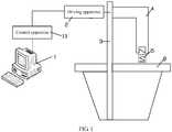
FIG. 1 is a schematic structural view of a capsule endoscope control system according to an embodiment of the present invention; -
FIGS. 2 and3 are schematic structural views of a capsule endoscope control device according to an embodiment of the present invention; -
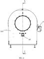
FIG. 4 is a schematic structural rear view of a capsule endoscope control device according to an embodiment of the present invention; -
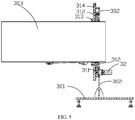
FIG. 5 is a schematic sectional view taken along an S-S direction inFIG. 4 ; -
FIG. 6 is a schematic structural view of a capsule endoscope control device covered with a cylinder according to an embodiment of the present invention; -
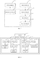
FIG. 7 is a schematic structural view of a control apparatus in a capsule endoscope control system according to an embodiment of the present invention; -
FIG. 8 is a schematic structural view of a driving apparatus in a capsule endoscope control device according to an embodiment of the present invention; -
FIG. 9 is a schematic internal structural view of a capsule endoscope according to an embodiment of the present invention; -
FIG. 10 is a schematic view of the side of the capsule endoscope with a lens close to an inner wall of the human body according to an embodiment of the present invention; -
FIG. 11 is a schematic view of the side of the capsule endoscope without a lens close to an inner wall of the human body according to an embodiment of the present invention; and -
FIG. 12 is a schematic view of a capsule endoscope picking up images for an inner wall of the human body in different postures of a permanent magnet according to an embodiment of the present invention. - To make the objective, technical solution, and advantages of the present invention more clear, the following section describes the technical solutions of the present invention in combination with the accompanying drawings and embodiments. It should be understood that the embodiments described here are only exemplary ones for illustrating the present invention, and are not intended to limit the present invention.
-
FIG. 1 illustrates a structure of a capsule endoscope control system according to an embodiment of the present invention. For ease of description, parts relevant to the embodiments of the present invention are only illustrated. - In the embodiment of the present invention, the capsule endoscope control system comprises a
control apparatus 11 running on aterminal 1, and a capsule endoscope control device controllable by thecontrol device 11. - The capsule endoscope control device comprises: a
frame 30, arotating apparatus 3, amovement arm 4, apermanent magnet 5, and adriving apparatus 2. - The
rotating apparatus 3 is disposed on theframe 30. - The
movement arm 4 is secured to therotating apparatus 3, and a tail end of themovement arm 4 is provided with thepermanent magnet 5. - The
driving apparatus 2 is electrically connected to therotating apparatus 3 and themovement arm 4, and configured to receive an external movement control instruction, drive therotating apparatus 3, themovement arm 4 and thepermanent magnet 5 to move, and control position and posture of the capsule endoscope in a human body via a magnetic force of thepermanent magnet 5. - The
control apparatus 11 running on theterminal 1 is communicated with thedriving apparatus 2, and configured to provide an operation interface for a user, transmit a movement control instruction of the user to thedriving apparatus 2, store and process image data collected by the capsule endoscope from the human body. - The
control apparatus 11 is communicated with the capsule endoscope in a wireless manner, and may be communicated with thedriving apparatus 2 in a wired manner or in a wireless manner. - In the embodiment of the present invention, the capsule endoscope control device employs an electrical control manner, and the
driving apparatus 2 controls movement of therotating apparatus 3 and themovement arm 4. Since themovement arm 4 is secured to the rotatingapparatus 3, when therotating apparatus 3 rotates, themovement arm 4 is driven to rotate as well, and meanwhile position and posture of thepermanent magnet 5 are changed by regulating posture of themovement arm 4, thereby ensuring that thepermanent magnet 5 is capable of traversing all positions in an examination region. - Referring to
FIG. 1 to FIG. 3 , theframe 30 comprises abase 301 supported on the ground, and aback plate 302 perpendicularly secured to thebase 301 along a longitudinal direction. The rotatingapparatus 3 is secured in an overlay manner to theback plate 302. Theback plate 302 is provided with a through hole. - One end of the
movement arm 4 is secured to a side surface of therotating apparatus 3, and the other end of themovement arm 4 telescopically rotatably extends along a transverse direction. - The
permanent magnet 5 is disposed at a tail end of themovement arm 4. When the capsule endoscope is taken by an examinee, the taken capsule endoscope is controlled by thepermanent magnet 5. - The
driving apparatus 2 is electrically connected to therotating apparatus 3 and themovement arm 4, and configured to electrically control therotating apparatus 3, themovement arm 4, and thepermanent magnet 5. - There are
multiple motors 32, which are separately disposed on therotating apparatus 3 and themovement arm 4, and enables, according to the control instruction sent by theterminal 1 to the drivingapparatus 2, thedriving apparatus 2 to adjust the positions of therotating apparatus 3 and themovement arm 4 so as to drive thepermanent magnet 5 to reach the designated examination region. - The
rotating apparatus 3 is in a hollow disk shape, and forms areceiving chamber 303 with a through hole opened on theback plate 302. - The
receiving chamber 303 is configured to accommodate an examinee and is in a cylinder shape, is communicated with therotating apparatus 3 and theback plate 302, and extends towards a stretching direction of themovement arm 4. - One end of the
movement arm 4 is vertically secured to the rotatingapparatus 3, and the other end of themovement arm 4 is movable on the outer side of thereceiving chamber 303. There aremultiple arm rods 41 that are sequentially connected. - Referring to
FIG. 2 to FIG. 5 , the hollow disk-shapedrotating apparatus 3 comprises adriving wheel 311, a drivenwheel 312, and abearing 313. - The
driving wheel 311 is securely disposed on one side at the bottom of theback plate 302, and amotor 32 connected to thedriving wheel 311 is disposed on the other side of theback plate 302, wherein themotor 32 is configured to drive thedriving wheel 311. - The driven
wheel 312 is engaged with thedriving wheel 311, and is rotatably connected to an outer ring of thebearing 313. - The
bearing 313 is in hollow annular shape, and is secured to theback plate 302. Thereceiving chamber 303 is communicated with thebearing 313 and theback plate 302. - A guiding
plate 314 is secured in an overlay manner to one side of theback plate 302. The guidingplate 314 is positioned on an outer ring at the bottom of the drivenwheel 312. - An outer edge of the
guiding plate 314 extends towards one side of themovement arm 4 to define acircular baffle 315, and aprotrusion portion 316 being formed upwardly in a position close to the drivenwheel 312 on an inner ring of theguiding plate 314. Thebaffle 315, the guidingplate 314, and theprotrusion portion 316 define an annular guidinggroove 317 therebetween. - When the
rotating apparatus 3 drives themovement arm 4 to rotate, the activity space of aconnection cable 401 of themovement arm 4 is provided. Theconnection cable 401 may be a signal cable and a power cable of themovement arm 4. To make theconnection cable 401 tidy and beautiful, theconnection cable 401 is sleeved with adrag chain 402. Thedrag chain 402 may be freely bent, and movable in the guidinggroove 317. - An
installation plate 318 is secured to a top surface of the drivenwheel 312, and one end of themovement arm 4 is secured to theinstallation plate 318. When the drivenwheel 312 rotates, theinstallation plate 318 rotates accordingly and drives themovement arm 4 to rotate. - The
installation plate 318 is in a planar structure, and spans over the guidinggroove 317. One end of theinstallation plate 318 is secured to the drivenwheel 312, and the other end extends outside thecircular baffle 315, such that theinstallation plate 318 will not disturb thedrag chain 402 in the guidinggroove 317 during the process of rotating. - Referring to
FIGS. 2 and3 , themovement arm 4 has at least twoarm rods 41 connected with each other. Themotor 32 is separately disposed between thearm rods 41, and between thearm rods 41 and therotating apparatus 3. - When the
arm rods 41 connect themotor 32, themovement arm 4 can stretch and rotate, and the stretching direction of themovement arm 4 is consistent with the receivingchamber 303. When an examinee is in the receivingchamber 303, therotating apparatus 3 may rotate at 360 degrees, and drive themovement arm 4 to rotate round the receivingchamber 303, such that the examinee receives an all-round thorough examination. When an examination region is selected, therotating apparatus 3 stops rotating, and the positions of thearm rods 41 are adjusted, such that thepermanent magnet 5 traverses all positions in the examination region. - As a preferred embodiment of the present invention, the
movement arm 4 may comprise afirst arm rod 411, asecond arm rod 412, and athird arm rod 413 that are connected to each other. - One end of the
first arm rod 411 is secured to therotating apparatus 3; one end of thesecond arm rod 412 is connected to the other end of thefirst arm rod 411; and one end of thethird arm rod 413 is connected to the other end of thesecond arm rod 412, and the other end of thethird arm rod 413 is connected to thepermanent magnet 5. Themotor 32 is separately disposed between thefirst arm rod 411 and therotating apparatus 3, between thefirst arm rod 411 and thesecond arm rod 412, and between thesecond arm rod 412 and thethird arm rod 413. - Specifically, the
first arm rod 411 is secured to a side surface of the drivenwheel 312 via theinstallation plate 318, and themotor 32 is disposed between thefirst arm rod 411 and the drivenwheel 312. Themotor 32 is separately disposed between thefirst arm rod 411 and thesecond arm rod 412, and between thesecond arm rod 412 and thethird arm rod 413. Thepermanent magnet 5 is disposed on thethird arm rod 413. Compared with themovement arm 4 using twoarm rods 41, themovement arm 4 using threearm rods 41 can reduce the length of asingle arm rod 41, and can more flexibly control thepermanent magnet 5 disposed at a tail end. - As another embodiment of the present invention, the
movement arm 4 has two arm rods: afirst arm rod 411, and asecond arm rod 412. - One end of the
first arm rod 411 is secured to therotating apparatus 3. One end of thesecond arm rod 412 is connected to the other end of thefirst arm rod 411, and the other end of thesecond arm rod 412 is connected to thepermanent magnet 5. Themotor 32 is separately disposed between thefirst arm rod 411 and therotating apparatus 3, between thefirst arm rod 411 and thesecond arm rod 412, and between thesecond arm rod 412 and thepermanent magnet 5. In this way, thethird arm rod 413 in the above embodiment is replaced by using the length of themotor 32, thepermanent magnet 5 is placed on the output end of themotor 32, and the same effects as thethird arm rod 413 are achieved by using the length of themotor 32, thereby saving space. - Referring to
FIG. 6 , to make capsule endoscope control system more beautiful, and ensure the security of an examinee, therotating apparatus 3 andmovement arm 4 can be covered in acylinder 304. Thecylinder 304 extends along the stretching direction of themovement arm 4, and the receivingchamber 303 penetrates through thecylinder 304 along an axial direction. Themovement arm 4 using threearm rods 41 can make the diameter of thecylinder 304 smaller after the length of asingle arm rod 41 is reduced. Under the same circumstances of traversing any position of the space of thecylinder 304, thecylinder 304 of the smaller size reduces the volume of entire capsule endoscope control system, which thus reduces space and saves manufacture costs. - Specifically, the
motor 32 in the embodiment of the present invention is a servo motor. - The motor disposed between the
first arm rod 411 and the drivenwheel 312 comprises afirst motor 321 and asecond motor 322. - The
first motor 321 is secured to the drivenwheel 312 along a transverse direction, and the output end of thefirst motor 321 is connected to thesecond motor 322; and thesecond motor 322 is disposed along a longitudinal direction, and the output end of thesecond motor 322 is connected to thefirst arm rod 411. In this way, thefirst motor 321 rotates along a transverse axle A at 360 degrees, and the output end of thesecond motor 322 rotates at 360 degrees along a longitudinal axle B in a vertical plane of thefirst motor 321. - The motor disposed between the
first arm rod 411 and thesecond arm rod 412 is athird motor 323. Thethird motor 323 is disposed along a longitudinal direction, and the output end of thethird motor 323 is connected to thesecond arm rod 412. In this way, the output end of thethird motor 323 rotates at 360 degrees along a longitudinal axle C in a vertical plane of thefirst arm rod 411. - The motors disposed between the
second arm rod 412 and thethird arm rod 413 are a fourth motor 324, a fifth motor 325, and a sixmotor 326 that are sequentially connected. - The fourth motor 324 is disposed along a longitudinal direction; the fifth motor 325 is disposed along a transverse direction, and connected to the output end of the fourth motor 324; the six
motor 326 is disposed along a longitudinal direction, and connected to the output end of the fifth motor 325; and thepermanent magnet 5 is disposed on the output end of the sixmotor 326. In this way, the fourth motor 324 rotates at 360 degrees along a longitudinal axle D in a vertical plane of thesecond arm rod 412, the fifth motor 325 rotates at 360 degrees along a transverse axle E in a vertical plane of the fourth motor 324, and the sixmotor 326 drives thepermanent magnet 5 along a longitudinal axle F in a vertical plane vertical to the fifth motor 325 to rotate at 360 degrees. - Therefore, by adjusting angles of various motors, and flexibly controlling positions of
arm rods 41 andpermanent magnet 5, thepermanent magnet 5 reaches entire position in the region of thecylinder 304. - A
control apparatus 11 runs on theterminal 1, is configured to control running states of the entire capsule endoscope control system, and is communicated with the drivingapparatus 2. - The operation interface of the
control apparatus 11 comprises various function options. A user may directly operate on the operation interface such as, selecting working mode, or inputting other relevant information, for example, controlling position of the examination couch 8. - In addition, the
control apparatus 11 internally contains instruction programs corresponding to various functions on the operation interface. After a user selects a function option, thecontrol apparatus 11 sends the corresponding instruction to thedriving apparatus 2. In this way, the user can control running of the capsule endoscope control system by using thecontrol apparatus 11. - Referring to
FIG. 7 , thecontrol apparatus 11 comprises: aninstruction receiving unit 111, adata receiving unit 112, adata storing unit 113, and adata processing unit 114. Theinstruction receiving unit 111 is configured to transmit a control instruction input by the user to thedriving apparatus 2. - The
data receiving unit 112 is configured to receive image data collected and output by acapsule endoscope 7 from a human body. - The
data storing unit 113 is configured to store the image data received by thedata receiving unit 112. - The
data processing unit 114 is configured to process, according to user's operations, the image data such as, browse, edit, and tag, stored by thedata storing unit 113. - In an embodiment of the present invention, the
terminal 1 is a computer, and may also be another upper-level computer capable of implementing the same functions. - The driving
apparatus 2 comprises an input interface, a PLC module, a power module, and an output interface that are electrically connected; wherein: the input interface is configured to receive a movement control instruction input over theterminal 1, the PLC module is configured to perform an operation on the movement control instruction and output a movement control signal, the output interface is configured to output the movement control signal to therotating apparatus 3 or themovement arm 4, and the power module is configured to supply power to the PLC module. - Referring to
FIG. 8 , the drivingapparatus 2 is divided into a rotatingapparatus driving module 21, and a movementarm driving module 22. The motor driving thedriving wheel 311 is a rotating apparatus motor, and the motor disposed on each arm rod of themovement rod 4 is a movement arm motor. - Specifically, the rotating
apparatus driving module 21 internally comprises: an input interface 211, a PLC module 212, apower supply module 213, a powersupply protection circuit 214, and anoutput interface 215. - The input interface 211 is configured to receive instruction information transmitted by the
terminal 1, and transmit the instruction information to the PLC module 212. The PLC module 212 internally stores logical operation programs. After receiving an input signal, the PLC module 212 runs the corresponding program according to the input signal, generates an output signal, and finally transmits the output signal to theoutput interface 215. Theoutput interface 215 transmits the output signal to therotating apparatus 3 to control rotation of the motor in therotating apparatus 3. - The
power supply module 213 is configured to supply power to the PLC module 212. - The power
supply protection circuit 214 is configured to protect thepower supply module 213 to prevent exceptions of over-voltage, over-temperature, and over-current. - The movement
arm driving module 22 internally comprises: aninput interface 221, aPLC module 222, apower supply module 223, a power supply protection circuit 224, and anoutput interface 225. - The
input interface 221 is configured to receive instruction information transmitted by theterminal 1, and transmit the instruction information to thePLC module 222. - The
PLC module 222 internally stores logical operation programs. After receiving an input signal, thePLC module 222 runs the corresponding program according to the input signal, and finally transmits an output signal to theoutput interface 225. Theoutput interface 225 transmits the output signal to themovement arm 4 to control themovement arm 4 to implement corresponding movement. - The
power supply module 223 is configured to supply power to thePLC module 222. - The power supply protection circuit 224 is configured to protect the
power supply module 223 to prevent exceptions of over-voltage, over-temperature, and over-current. - The output signal transmitted by the rotating
apparatus driving module 21 to therotating apparatus 3 comprises: an angular velocity and rotation angle information of the rotation of the rotating apparatus motor. For example, when a pulse signal is selected as the output signal, the pulse frequency of the pulse signal and the number of pulse signals may be used to correspond to the angular velocity and the rotation angle according to an agreement. After receiving a signal, the rotating apparatus motor rotates at a corresponding angle at a corresponding angular velocity. Therotating apparatus 3 may be subjected to 360 degrees rotation. - The movement
arm driving module 22 may transmit a signal to any motor on themovement arm 4. Under driving of the motor, each arm rod may move up, down, left, and right. Therefore, themovement arm 4 moves to a designated position within a specific range under cooperation of the arm rods thereof. - The output signal transmitted by the movement
arm driving module 22 comprises such information as movement direction and distance of the arm rods. For example, when a pulse signal is selected as the output signal, the pulse frequency of the pulse signal and the number of pulse signals may be used to correspond to the movement direction and distance of arm rods according to an agreement. Under the cooperative action of the arm rods of themovement rod 4, themovement rod 4 may change the position of thepermanent magnet 5 through a series of operations such as shrink and move, and may also control thepermanent magnet 5 through a rotation operation to rotate at 360 degrees with a peripheral point as a center of circle, or to self-rotate at 360 degrees with the center of thepermanent magnet 5 as an axle. Through the above operations, themovement rod 4 changes the position and posture of thepermanent magnet 5. - Referring to
FIG. 1 , as a preferable embodiment of the present invention, to facilitate examination on an examinee, an examination couch 8 is disposed below therotating apparatus 3 and themovement arm 4. The examination couch 8 is configured to support an examinee, and may be movably pushed. - The examination couch 8 horizontally passes through the
rotating apparatus 3 and is thus placed, and is configured to accommodate the examinee taking a controllable capsule endoscope in the body. After taking a capsule endoscope, the examinee lies down on the examination couch 8. Under the control of the capsule endoscope control system, thepermanent magnet 5 may reach a series of different positions around the examinee and stay in different postures. Because the magnetic material in the capsule endoscope is subjected to a magnetic force, the position of thepermanent magnet 5 may change under traction of the magnetic force, the movement direction of the capsule endoscope may also change, and finally the capsule endoscope may move to the position corresponding to thepermanent magnet 5. If the posture of thepermanent magnet 5 changes, the posture of the capsule endoscope may correspondingly change. - The method for controlling capsule endoscope in the body by using the
permanent magnet 5 in the capsule endoscope control system is specifically described hereinafter. - As illustrated in
FIG. 9 , thecapsule endoscope 7 in the embodiment of the present invention comprises: acapsule housing 71, alens hood 72, and alens 73 internally disposed therein, an LEDlight source component 74, a magnet 75, and acircuit board 76, abattery 77, and anantenna 78. - Only a group of
lens 73 is selected in the embodiment of the present invention, thelens hood 72 is disposed on a periphery of thelens 73, thebattery 77 is connected to thecircuit board 76, and theantenna 78 is connected to thecircuit board 76. The selected magnetic material in the embodiment of the present invention is magnet 75 disposed on a periphery of thebattery 77. The magnet 75 is subjected to a magnetic force in the magnetic field to change the movement state of thecapsule endoscope 7. - As illustrated in
FIG. 10 , the side of thecapsule endoscope 7 with a lens needs to be disposed close to the stomach wall when images of the stomach wall in a specific position need to be clearly picked up. - The capsule endoscope control system controls the
permanent magnet 5 to be located at a specific position close to the stomach in the human body, and the S pole of thepermanent magnet 5 points to the human body, and the N pole points to the opposite. Under traction of the magnetic force, thecapsule endoscope 7 moves towards the direction of the S pole of thepermanent magnet 5. When moving to the stomach wall close to the S pole of the permanent magnet, thecapsule endoscope 7 stops moving. Because the magnetic pole of the magnet has the features of "like charges repel each other while unlike charges attract", the N pole of thepermanent magnet 5 points to the stomach wall, and the N pole points to the opposite. Accordingly, the side of thecapsule endoscope 7 with a lens is disposed close to the stomach wall, and the side without a lens is disposed close to the opposite. At this moment, images in a series of the corresponding positions of the stomach wall can be picked up in a short distance. With the same method, the capsule endoscope control system controls thepermanent magnet 5 to be located at different positions close to the stomach in the human body, and thus images in a series of the corresponding positions of the stomach wall can be precisely picked up. - As illustrated in
FIG. 11 , the side of thecapsule endoscope 7 without a lens needs to be disposed close to the stomach wall when a large range of images need to be picked up. - The specific implementing method is as follows: the capsule endoscope control system controls the
permanent magnet 5 to be located at a specific position close the stomach in the human body, the N pole points to the human body, and the S pole points to the opposite. Under traction of the magnetic force, thecapsule endoscope 7 moves towards the direction of the N pole of the permanent magnet. When moving to the stomach wall close to the N pole of the permanent magnet, thecapsule endoscope 7 stops moving, the S pole of thepermanent magnet 5 points to the stomach wall, and the N pole points to the opposite. Correspondingly, the side of thecapsule endoscope 7 without a lens is disposed close to the stomach wall, and the side with a lens is disposed close to the opposite. At this moment, images within a large range of the stomach wall of the human body can be picked up in a remote distance. With the same method, the capsule endoscope control system controls thepermanent magnet 5 to be located in different positions close to the stomach in the human body, and thus images in a series of the corresponding positions of the stomach wall can be picked up. -
FIG. 12 illustrates a method for changing postures of thecapsule endoscope 7 by changing postures of thepermanent magnet 5. - The capsule endoscope control system controls the
permanent magnet 5 to be located in a specific position that forms an angle θ (0 < θ < 180) with the human body. The N pole points to the human body at an angle θ, and the S pole points to the opposite. Under traction of the magnetic force, thecapsule endoscope 7 finally moves to the position as illustrated inFIG. 12 , the side of thecapsule endoscope 7 without a lens points to the stomach wall at the angle θ, and the side with a lens points to the opposite. In this way, thepermanent magnet 5 is controlled in different postures by changing the angle θ, which can make thecapsule endoscope 7 in different postures, such that the image can be picked up at any angle in the original position. - According to the embodiments of the present invention, by means of electrical control, the driving apparatus controls movement of the rotating apparatus and the movement arm, the permanent magnet disposed on the movement arm controls position and posture of the capsule endoscope in the human body, such that the capsule endoscope picks up complete images on the stomach, and accuracy and precision of medical diagnosis are improved.
- Described above are merely preferred embodiments of the present invention, but are not intended to limit the present invention.
Claims (13)
- A capsule endoscope control device (11), comprising:a frame (30) comprising a base (301) supported on the ground, and a back plate (302) perpendicularly secured to
the base (301) along a longitudinal direction;a rotating apparatus (3), disposed on the frame (30) and secured to the back plate;a movement arm (4), secured to the rotating apparatus (3), a tail end of the movement arm (4) being provided with a permanent magnet (5); anda driving apparatus (2), electrically connected to the rotating apparatus (3) and the movement arm (4), and configured to receive an external movement control instruction, drive the rotating apparatus, the movement arm [4] and the permanent magnet (5) to move, and control position and posture of the capsule endoscope (7) in a human body via a magnetic force of the permanent magnet (5);characterised in that:
the rotating apparatus comprises:a driving wheel (311), securely disposed on one side of the back plate (302);a driving wheel motor, securely disposed on the other side of the back plate (302), and electrically connected to the driving wheel;a bearing (313), secured to the back plate (302); anda driven wheel (312), engaged with the driving wheel (311), and rotatably connected to an outer ring of the bearing. - The capsule endoscope control device according to claim 1, wherein the back
plate (302) is provided with a through hole;
the bearing (313) is in a hollow annular shape;
wherein the through hole is communicated with a hollow position of the bearing (313) to define a receiving chamber (303) for accommodating an examinee; and
the movement arm (4) is positioned on an outer side of the receiving chamber (303). - The capsule endoscope control device according to claim 1, wherein a guiding plate (314) is secured in an overlay manner to one side of the back plate (302);
wherein the guiding plate (314) is positioned on an outer ring at a bottom side of the driven wheel (312); and
an outer edge of the guiding plate (314) extends towards one side of the movement arm (4) to define a circular baffle (315), a protrusion portion (316) being formed upwardly in a position close to the driven wheel on an inner ring of the guiding plate (314);
the baffle (315), the guiding plate (314), and the protrusion portion (316) defining an annular guiding groove (317);
the guiding groove (317) being internally provided with a connection cable (401) of the movement arm (4). - The capsule endoscope control device according to claim 1, wherein an installation plate (318) is secured to a top surface of the driven wheel (312), and one end of the movement arm (4) is secured to the installation plate (318).
- The capsule endoscope control device according to claim 1, wherein the movement arm (4) comprises:a first arm rod (411), one end of the first arm rod being secured to the rotating apparatus (3); and a second arm rod (412), one end of the second arm rod (412) being connected to the other end of the first arm rod (411), and the other end of the second arm rod being connected to the permanent magnet (5);wherein a motor is separately disposed between the first arm rod (411) and the rotating apparatus (3), between the first arm rod (411) and the second arm rod (412), and between the second arm rod (412) and the permanent magnet (5).
- The capsule endoscope control device according to claim 1, wherein the movement arm (4) comprises:a first arm rod (411), one end of the first arm rod (411) being secured to the rotating apparatus (3);a second arm rod (412), one end of the second arm rod being connected to the other end of the first arm rod (411); anda third arm rod (413), one end of the third arm rod (413) being connected to the other end of the second arm rod (412), and the other end of the third arm rod (413) being connected to the permanent magnet (5);wherein a motor is separately disposed between the first arm rod (411) and the rotating apparatus (3), between the first arm rod (411) and the second arm rod (412), and between the second arm rod and the third arm rod (413).
- A capsule endoscope control system, comprising a capsule endoscope control device (11) as claimed in claim 1 and
a control apparatus, communicated with the driving apparatus (2), and configured to provide an operation interface for a user, transmit a movement control instruction of the user to the driving apparatus (2), store and process image data collected by the capsule endoscope (7) from the human body. - The capsule endoscope control system according to claim 7, wherein the back plate (302) is provided with a through hole;
the bearing (313) is in a hollow annular shape;
wherein the through hole is communicated with a hollow position of the bearing to define a receiving chamber (303) for accommodating an examinee and the movement arm (4) is positioned on an outer side of the receiving chamber (303). - The capsule endoscope control system according to claim 7, wherein a guiding plate is secured in an overlay manner to one side of the back plate (302);
wherein the guiding plate (314) is positioned on an outer ring at a bottom side of the driven wheel (312); and
an outer edge of the guiding plate (314) extends towards one side of the movement arm to define a circular baffle (315), a protrusion portion (316) being formed upwardly in a position close to the driven wheel on an inner ring of the guiding plate (314);
the baffle (315), the guiding plate (314), and the protrusion portion (316) defining an annular guiding groove (317);
the guiding groove (317) being internally provided with a connection cable (401) of the movement arm (4). - The capsule endoscope control system according to claim 7, wherein an installation plate (318) is secured to a top surface of the driven wheel (312), and one end of the movement arm (4) is secured to the installation plate (318).
- The capsule endoscope control system according to claim 7, wherein the movement arm comprises:a first arm rod (411), one end of the first arm rod (411) being secured to the rotating apparatus (3);a second arm rod (412), one end of the second arm rod (412) being connected to the other end of the first arm rod (411), and the other end of the second arm rod (412) being connected to the permanent magnet (5);wherein a motor is separately disposed between the first arm rod (411) and the rotating apparatus (3), between the first arm rod (411) and the second arm rod (412), and between the second arm rod (412) and the permanent magnet (5).
- The capsule endoscope control system according to claim 7, wherein the movement arm (4) comprises:a first arm rod (411), one end of the first arm rod being secured to the rotating apparatus (3);a second arm rod (412), one end of the second arm rod (412) being connected to the other end of the first arm rod (411); anda third arm rod (413), one end of the third arm rod (413) being connected to the other end of the second arm rod (412), and the other end of the third arm rod (413) being connected to the permanent magnet (5);wherein a motor is separately disposed between the first arm rod (411) and the rotating apparatus (3), between the first arm rod (411) and the second arm rod (412), and between the second arm rod (412) and the third arm rod (413).
- The capsule endoscope control system according to claim 7, wherein the control apparatus comprises:an instruction receiving unit (111), configured to transmit the movement control instruction input by the user to the driving apparatus (2);a data receiving unit (113), configured to receive the image data collected and output by the capsule endoscope (7) from the human body;a data storing unit (113), configured to store the image data received by the data receiving unit; anda data processing unit (114), configured to process, according to user's operations, the image data stored by the data storing unit (113).
Applications Claiming Priority (3)
| Application Number | Priority Date | Filing Date | Title |
|---|---|---|---|
| CN201410353836 | 2014-07-23 | ||
| CN201410416049.5A CN104146676B (en) | 2014-07-23 | 2014-08-21 | A kind of capsule endoscope control appliance and system |
| PCT/CN2015/083630 WO2016011895A1 (en) | 2014-07-23 | 2015-07-09 | Controlling equipment and system of capsule endoscope |
Publications (3)
| Publication Number | Publication Date |
|---|---|
| EP3033986A1 EP3033986A1 (en) | 2016-06-22 |
| EP3033986A4 EP3033986A4 (en) | 2017-05-03 |
| EP3033986B1 true EP3033986B1 (en) | 2018-10-24 |
Family
ID=51872469
Family Applications (1)
| Application Number | Title | Priority Date | Filing Date |
|---|---|---|---|
| EP15824193.5A Not-in-force EP3033986B1 (en) | 2014-07-23 | 2015-07-09 | Controlling equipment and system of capsule endoscope |
Country Status (5)
| Country | Link |
|---|---|
| US (1) | US20160022124A1 (en) |
| EP (1) | EP3033986B1 (en) |
| JP (1) | JP6231213B2 (en) |
| CN (1) | CN104146676B (en) |
| WO (1) | WO2016011895A1 (en) |
Families Citing this family (16)
| Publication number | Priority date | Publication date | Assignee | Title |
|---|---|---|---|---|
| CN104146676B (en) * | 2014-07-23 | 2015-12-02 | 深圳市资福技术有限公司 | A kind of capsule endoscope control appliance and system |
| US9974980B2 (en) * | 2015-12-31 | 2018-05-22 | Shanghai United Imaging Healthcare Co., Ltd. | Radiation therapy system |
| CN105615997A (en) * | 2016-02-25 | 2016-06-01 | 鑫麦源创时代医疗科技(苏州)有限公司 | Minimally-invasive intervention ablation system with control-type mechanical arm |
| CN105662578A (en) * | 2016-02-25 | 2016-06-15 | 鑫麦源创时代医疗科技(苏州)有限公司 | Puncture needle propelling mechanical arm and ablation system using same |
| US10478047B2 (en) * | 2016-09-23 | 2019-11-19 | Ankon Medical Technologies (Shanghai) Co., Ltd | System and method for using a capsule device |
| CN206576844U (en) * | 2016-11-15 | 2017-10-24 | 深圳市资福技术有限公司 | A kind of capsule gastroscope magnetic control system |
| CN107049213A (en) * | 2017-03-28 | 2017-08-18 | 重庆金山医疗器械有限公司 | A kind of capsule endoscope control method and device |
| CN107374572A (en) * | 2017-07-05 | 2017-11-24 | 上海楠青自动化科技有限公司 | A kind of magnet Universal rotary device to be navigated in vitro for capsule endoscopic |
| CN108420391A (en) * | 2018-01-29 | 2018-08-21 | 重庆金山医疗器械有限公司 | A kind of capsule endoscope control device, system and method |
| US11426059B2 (en) * | 2018-06-02 | 2022-08-30 | Ankon Medical Technologies (Shanghai) Co., Ltd. | Control system for capsule endoscope |
| CN112336293A (en) * | 2019-08-08 | 2021-02-09 | 上海安翰医疗技术有限公司 | Remote control system and remote control method of magnetic capsule endoscope |
| CN112336292A (en) * | 2019-08-08 | 2021-02-09 | 上海安翰医疗技术有限公司 | Method and apparatus for controlling magnetic capsule endoscope control system, and storage medium |
| CN110837183A (en) * | 2019-11-27 | 2020-02-25 | 格力电器(武汉)有限公司 | Device and method for inspecting inner container of water heater |
| CN113100940B (en) * | 2021-04-09 | 2022-09-13 | 哈尔滨工业大学(深圳) | Multi-point magnetic control catheter navigation system and use method thereof |
| CN113171179B (en) * | 2021-04-25 | 2023-07-14 | 上海微创医疗机器人(集团)股份有限公司 | Surgical robot |
| CN114259197B (en) * | 2022-03-03 | 2022-05-10 | 深圳市资福医疗技术有限公司 | Capsule endoscope quality control method and system |
Family Cites Families (19)
| Publication number | Priority date | Publication date | Assignee | Title |
|---|---|---|---|---|
| US5107121A (en) * | 1989-10-27 | 1992-04-21 | Trionix Research Laboratory, Inc. | Gantry and pallet assembly used in nuclear imaging |
| DE10343494B4 (en) * | 2003-09-19 | 2006-06-14 | Siemens Ag | Magnetically navigable device for use in the field of medical endoscopy |
| DE102005015374A1 (en) * | 2005-03-30 | 2006-10-05 | Schreiber, Hans, Dr. Dr. | Controllable capsule endoscope for colonoscopy is included in kit that also includes height adjustable table, suction device, vacuum table and control unit |
| US7465928B2 (en) * | 2005-09-29 | 2008-12-16 | Siemens Medical Solutions Usa, Inc. | Apparatus and methods for guiding cables around a rotating gantry of a nuclear medicine camera |
| WO2007083708A1 (en) * | 2006-01-19 | 2007-07-26 | Olympus Medical Systems Corp. | In vovo medical system, method of operating body-insertable device, and method of surgery |
| JP5226538B2 (en) * | 2007-02-14 | 2013-07-03 | オリンパスメディカルシステムズ株式会社 | Operating device, monitoring device, and capsule guiding system |
| DE102007041346A1 (en) * | 2007-08-31 | 2009-03-05 | Siemens Ag | Position measuring and guiding device |
| KR100960289B1 (en) * | 2008-02-29 | 2010-06-07 | 한국항공대학교산학협력단 | Endoscope system |
| US8237123B2 (en) * | 2008-11-13 | 2012-08-07 | General Electric Company | Apparatus for preventing damage to retractor in rotating imaging system |
| CN101732026B (en) * | 2009-12-04 | 2011-04-20 | 华中科技大学 | Magnetic-navigation motion control system for use in capsule endoscopy |
| WO2011072060A2 (en) * | 2009-12-08 | 2011-06-16 | Magnetecs Corporation | Diagnostic and therapeutic magnetic propulsion capsule and method for using the same |
| EP2347699B1 (en) * | 2010-01-22 | 2018-11-07 | Novineon Healthcare Technology Partners Gmbh | Capsule type endoscope including magnetic drive |
| US8989846B2 (en) * | 2010-08-08 | 2015-03-24 | Accuray Incorporated | Radiation treatment delivery system with outwardly movable radiation treatment head extending from ring gantry |
| DE102011054910B4 (en) * | 2011-10-28 | 2013-10-10 | Ovesco Endoscopy Ag | Magnetic end effector and means for guiding and positioning same |
| US20140288416A1 (en) * | 2013-03-22 | 2014-09-25 | University Of Utah Research Foundation | Manipulation of an untethered magentic device with a magnet actuator |
| CN103169443A (en) * | 2013-03-29 | 2013-06-26 | 哈尔滨工业大学深圳研究生院 | Magnetic control active capsule endoscope motion control system based on smart robot |
| CN103405211A (en) * | 2013-08-14 | 2013-11-27 | 深圳市资福技术有限公司 | System and method for controlling running state of capsule endoscope in body |
| CN204072036U (en) * | 2014-07-23 | 2015-01-07 | 深圳市资福技术有限公司 | A kind of capsule endoscope control appliance |
| CN104146676B (en) * | 2014-07-23 | 2015-12-02 | 深圳市资福技术有限公司 | A kind of capsule endoscope control appliance and system |
-
2014
- 2014-08-21 CN CN201410416049.5A patent/CN104146676B/en active Active
-
2015
- 2015-07-09 EP EP15824193.5A patent/EP3033986B1/en not_active Not-in-force
- 2015-07-09 JP JP2016535344A patent/JP6231213B2/en not_active Expired - Fee Related
- 2015-07-09 WO PCT/CN2015/083630 patent/WO2016011895A1/en active Application Filing
- 2015-07-15 US US14/799,731 patent/US20160022124A1/en not_active Abandoned
Non-Patent Citations (1)
| Title |
|---|
| None * |
Also Published As
| Publication number | Publication date |
|---|---|
| JP6231213B2 (en) | 2017-11-15 |
| US20160022124A1 (en) | 2016-01-28 |
| CN104146676A (en) | 2014-11-19 |
| EP3033986A4 (en) | 2017-05-03 |
| WO2016011895A1 (en) | 2016-01-28 |
| JP2016527068A (en) | 2016-09-08 |
| EP3033986A1 (en) | 2016-06-22 |
| CN104146676B (en) | 2015-12-02 |
Similar Documents
| Publication | Publication Date | Title |
|---|---|---|
| EP3033986B1 (en) | Controlling equipment and system of capsule endoscope | |
| US9125557B2 (en) | Magnetic maneuvering system for capsule endoscope | |
| EP2347699B1 (en) | Capsule type endoscope including magnetic drive | |
| Yang et al. | Deltamag: An electromagnetic manipulation system with parallel mobile coils | |
| CA3112875C (en) | Device implantation using a cartridge | |
| CN106020240B (en) | Cloud platform control system of autonomic playback calibration | |
| CN211749482U (en) | Magnetic spiral capsule endoscope and control system of capsule endoscope | |
| US11957861B2 (en) | Pen style wireless tattoo machine, system, and kits | |
| CN109998457A (en) | It is a kind of can radio transmitting image the passive highly integrated capsule robot of double hemisphere of master | |
| US9788883B2 (en) | Method and apparatus for in-vivo cauterization of lesions and malignancies | |
| CN108369641A (en) | Electronic equipment and bracket for it | |
| KR20200143728A (en) | Method for positioning and orienting portable systems and remote objects | |
| CN113037042B (en) | Capsule endoscope's magnetic control biopsy mechanism | |
| CN204072036U (en) | A kind of capsule endoscope control appliance | |
| Guo et al. | Design of a novel drug-delivery module for active locomotive intestinal capsule endoscopy | |
| US9743942B2 (en) | Nanotechnology and other small scale injectable machines with multistage external magnetic and electrostatic actuation | |
| CN112890743B (en) | Formula sampling device is inhaled to capsule endoscope magnetism | |
| CN113017542A (en) | Magnetic spiral capsule endoscope, magnetic spiral capsule endoscope control system and control method thereof | |
| CN203234717U (en) | Capsule endoscope and azimuth controlling device thereof | |
| CN103142205A (en) | Image acquisition method of capsule gastroscope | |
| CN217311030U (en) | Mechanical arm and massage robot | |
| KR102160729B1 (en) | Triaxial motion device | |
| CN115429199A (en) | Handheld magnetic control capsule driving device and driving method | |
| KR20130051145A (en) | Remote controlled fishing system and equipment using the smart phone and tablet pc based on wireless internet system | |
| CN211188805U (en) | Intelligent photon therapeutic instrument |
Legal Events
| Date | Code | Title | Description |
|---|---|---|---|
| PUAI | Public reference made under article 153(3) epc to a published international application that has entered the european phase |
Free format text: ORIGINAL CODE: 0009012 |
|
| 17P | Request for examination filed |
Effective date: 20160317 |
|
| AK | Designated contracting states |
Kind code of ref document: A1 Designated state(s): AL AT BE BG CH CY CZ DE DK EE ES FI FR GB GR HR HU IE IS IT LI LT LU LV MC MK MT NL NO PL PT RO RS SE SI SK SM TR |
|
| AX | Request for extension of the european patent |
Extension state: BA ME |
|
| A4 | Supplementary search report drawn up and despatched |
Effective date: 20170331 |
|
| RIC1 | Information provided on ipc code assigned before grant |
Ipc: A61B 5/07 20060101ALI20170327BHEP Ipc: A61B 1/273 20060101ALI20170327BHEP Ipc: A61B 1/04 20060101AFI20170327BHEP Ipc: A61B 1/00 20060101ALI20170327BHEP |
|
| DAV | Request for validation of the european patent (deleted) | ||
| DAX | Request for extension of the european patent (deleted) | ||
| GRAP | Despatch of communication of intention to grant a patent |
Free format text: ORIGINAL CODE: EPIDOSNIGR1 |
|
| STAA | Information on the status of an ep patent application or granted ep patent |
Free format text: STATUS: GRANT OF PATENT IS INTENDED |
|
| INTG | Intention to grant announced |
Effective date: 20180518 |
|
| GRAS | Grant fee paid |
Free format text: ORIGINAL CODE: EPIDOSNIGR3 |
|
| GRAA | (expected) grant |
Free format text: ORIGINAL CODE: 0009210 |
|
| STAA | Information on the status of an ep patent application or granted ep patent |
Free format text: STATUS: THE PATENT HAS BEEN GRANTED |
|
| AK | Designated contracting states |
Kind code of ref document: B1 Designated state(s): AL AT BE BG CH CY CZ DE DK EE ES FI FR GB GR HR HU IE IS IT LI LT LU LV MC MK MT NL NO PL PT RO RS SE SI SK SM TR |
|
| REG | Reference to a national code |
Ref country code: CH Ref legal event code: EP |
|
| REG | Reference to a national code |
Ref country code: IE Ref legal event code: FG4D |
|
| REG | Reference to a national code |
Ref country code: AT Ref legal event code: REF Ref document number: 1055690 Country of ref document: AT Kind code of ref document: T Effective date: 20181115 |
|
| REG | Reference to a national code |
Ref country code: DE Ref legal event code: R096 Ref document number: 602015018867 Country of ref document: DE |
|
| REG | Reference to a national code |
Ref country code: NL Ref legal event code: MP Effective date: 20181024 |
|
| REG | Reference to a national code |
Ref country code: LT Ref legal event code: MG4D |
|
| REG | Reference to a national code |
Ref country code: AT Ref legal event code: MK05 Ref document number: 1055690 Country of ref document: AT Kind code of ref document: T Effective date: 20181024 |
|
| PG25 | Lapsed in a contracting state [announced via postgrant information from national office to epo] |
Ref country code: NL Free format text: LAPSE BECAUSE OF FAILURE TO SUBMIT A TRANSLATION OF THE DESCRIPTION OR TO PAY THE FEE WITHIN THE PRESCRIBED TIME-LIMIT Effective date: 20181024 |
|
| PG25 | Lapsed in a contracting state [announced via postgrant information from national office to epo] |
Ref country code: LT Free format text: LAPSE BECAUSE OF FAILURE TO SUBMIT A TRANSLATION OF THE DESCRIPTION OR TO PAY THE FEE WITHIN THE PRESCRIBED TIME-LIMIT Effective date: 20181024 Ref country code: NO Free format text: LAPSE BECAUSE OF FAILURE TO SUBMIT A TRANSLATION OF THE DESCRIPTION OR TO PAY THE FEE WITHIN THE PRESCRIBED TIME-LIMIT Effective date: 20190124 Ref country code: HR Free format text: LAPSE BECAUSE OF FAILURE TO SUBMIT A TRANSLATION OF THE DESCRIPTION OR TO PAY THE FEE WITHIN THE PRESCRIBED TIME-LIMIT Effective date: 20181024 Ref country code: BG Free format text: LAPSE BECAUSE OF FAILURE TO SUBMIT A TRANSLATION OF THE DESCRIPTION OR TO PAY THE FEE WITHIN THE PRESCRIBED TIME-LIMIT Effective date: 20190124 Ref country code: PL Free format text: LAPSE BECAUSE OF FAILURE TO SUBMIT A TRANSLATION OF THE DESCRIPTION OR TO PAY THE FEE WITHIN THE PRESCRIBED TIME-LIMIT Effective date: 20181024 Ref country code: FI Free format text: LAPSE BECAUSE OF FAILURE TO SUBMIT A TRANSLATION OF THE DESCRIPTION OR TO PAY THE FEE WITHIN THE PRESCRIBED TIME-LIMIT Effective date: 20181024 Ref country code: LV Free format text: LAPSE BECAUSE OF FAILURE TO SUBMIT A TRANSLATION OF THE DESCRIPTION OR TO PAY THE FEE WITHIN THE PRESCRIBED TIME-LIMIT Effective date: 20181024 Ref country code: ES Free format text: LAPSE BECAUSE OF FAILURE TO SUBMIT A TRANSLATION OF THE DESCRIPTION OR TO PAY THE FEE WITHIN THE PRESCRIBED TIME-LIMIT Effective date: 20181024 Ref country code: IS Free format text: LAPSE BECAUSE OF FAILURE TO SUBMIT A TRANSLATION OF THE DESCRIPTION OR TO PAY THE FEE WITHIN THE PRESCRIBED TIME-LIMIT Effective date: 20190224 Ref country code: AT Free format text: LAPSE BECAUSE OF FAILURE TO SUBMIT A TRANSLATION OF THE DESCRIPTION OR TO PAY THE FEE WITHIN THE PRESCRIBED TIME-LIMIT Effective date: 20181024 |
|
| PG25 | Lapsed in a contracting state [announced via postgrant information from national office to epo] |
Ref country code: PT Free format text: LAPSE BECAUSE OF FAILURE TO SUBMIT A TRANSLATION OF THE DESCRIPTION OR TO PAY THE FEE WITHIN THE PRESCRIBED TIME-LIMIT Effective date: 20190224 Ref country code: GR Free format text: LAPSE BECAUSE OF FAILURE TO SUBMIT A TRANSLATION OF THE DESCRIPTION OR TO PAY THE FEE WITHIN THE PRESCRIBED TIME-LIMIT Effective date: 20190125 Ref country code: SE Free format text: LAPSE BECAUSE OF FAILURE TO SUBMIT A TRANSLATION OF THE DESCRIPTION OR TO PAY THE FEE WITHIN THE PRESCRIBED TIME-LIMIT Effective date: 20181024 Ref country code: AL Free format text: LAPSE BECAUSE OF FAILURE TO SUBMIT A TRANSLATION OF THE DESCRIPTION OR TO PAY THE FEE WITHIN THE PRESCRIBED TIME-LIMIT Effective date: 20181024 Ref country code: RS Free format text: LAPSE BECAUSE OF FAILURE TO SUBMIT A TRANSLATION OF THE DESCRIPTION OR TO PAY THE FEE WITHIN THE PRESCRIBED TIME-LIMIT Effective date: 20181024 |
|
| REG | Reference to a national code |
Ref country code: DE Ref legal event code: R097 Ref document number: 602015018867 Country of ref document: DE |
|
| PG25 | Lapsed in a contracting state [announced via postgrant information from national office to epo] |
Ref country code: DK Free format text: LAPSE BECAUSE OF FAILURE TO SUBMIT A TRANSLATION OF THE DESCRIPTION OR TO PAY THE FEE WITHIN THE PRESCRIBED TIME-LIMIT Effective date: 20181024 Ref country code: IT Free format text: LAPSE BECAUSE OF FAILURE TO SUBMIT A TRANSLATION OF THE DESCRIPTION OR TO PAY THE FEE WITHIN THE PRESCRIBED TIME-LIMIT Effective date: 20181024 Ref country code: CZ Free format text: LAPSE BECAUSE OF FAILURE TO SUBMIT A TRANSLATION OF THE DESCRIPTION OR TO PAY THE FEE WITHIN THE PRESCRIBED TIME-LIMIT Effective date: 20181024 |
|
| PG25 | Lapsed in a contracting state [announced via postgrant information from national office to epo] |
Ref country code: SK Free format text: LAPSE BECAUSE OF FAILURE TO SUBMIT A TRANSLATION OF THE DESCRIPTION OR TO PAY THE FEE WITHIN THE PRESCRIBED TIME-LIMIT Effective date: 20181024 Ref country code: SM Free format text: LAPSE BECAUSE OF FAILURE TO SUBMIT A TRANSLATION OF THE DESCRIPTION OR TO PAY THE FEE WITHIN THE PRESCRIBED TIME-LIMIT Effective date: 20181024 Ref country code: EE Free format text: LAPSE BECAUSE OF FAILURE TO SUBMIT A TRANSLATION OF THE DESCRIPTION OR TO PAY THE FEE WITHIN THE PRESCRIBED TIME-LIMIT Effective date: 20181024 Ref country code: RO Free format text: LAPSE BECAUSE OF FAILURE TO SUBMIT A TRANSLATION OF THE DESCRIPTION OR TO PAY THE FEE WITHIN THE PRESCRIBED TIME-LIMIT Effective date: 20181024 |
|
| PLBE | No opposition filed within time limit |
Free format text: ORIGINAL CODE: 0009261 |
|
| STAA | Information on the status of an ep patent application or granted ep patent |
Free format text: STATUS: NO OPPOSITION FILED WITHIN TIME LIMIT |
|
| 26N | No opposition filed |
Effective date: 20190725 |
|
| PG25 | Lapsed in a contracting state [announced via postgrant information from national office to epo] |
Ref country code: SI Free format text: LAPSE BECAUSE OF FAILURE TO SUBMIT A TRANSLATION OF THE DESCRIPTION OR TO PAY THE FEE WITHIN THE PRESCRIBED TIME-LIMIT Effective date: 20181024 |
|
| REG | Reference to a national code |
Ref country code: DE Ref legal event code: R119 Ref document number: 602015018867 Country of ref document: DE |
|
| PG25 | Lapsed in a contracting state [announced via postgrant information from national office to epo] |
Ref country code: MC Free format text: LAPSE BECAUSE OF FAILURE TO SUBMIT A TRANSLATION OF THE DESCRIPTION OR TO PAY THE FEE WITHIN THE PRESCRIBED TIME-LIMIT Effective date: 20181024 |
|
| REG | Reference to a national code |
Ref country code: CH Ref legal event code: PL |
|
| GBPC | Gb: european patent ceased through non-payment of renewal fee |
Effective date: 20190709 |
|
| PG25 | Lapsed in a contracting state [announced via postgrant information from national office to epo] |
Ref country code: TR Free format text: LAPSE BECAUSE OF FAILURE TO SUBMIT A TRANSLATION OF THE DESCRIPTION OR TO PAY THE FEE WITHIN THE PRESCRIBED TIME-LIMIT Effective date: 20181024 |
|
| REG | Reference to a national code |
Ref country code: BE Ref legal event code: MM Effective date: 20190731 |
|
| PG25 | Lapsed in a contracting state [announced via postgrant information from national office to epo] |
Ref country code: GB Free format text: LAPSE BECAUSE OF NON-PAYMENT OF DUE FEES Effective date: 20190709 Ref country code: DE Free format text: LAPSE BECAUSE OF NON-PAYMENT OF DUE FEES Effective date: 20200201 |
|
| PG25 | Lapsed in a contracting state [announced via postgrant information from national office to epo] |
Ref country code: BE Free format text: LAPSE BECAUSE OF NON-PAYMENT OF DUE FEES Effective date: 20190731 Ref country code: CH Free format text: LAPSE BECAUSE OF NON-PAYMENT OF DUE FEES Effective date: 20190731 Ref country code: LI Free format text: LAPSE BECAUSE OF NON-PAYMENT OF DUE FEES Effective date: 20190731 Ref country code: LU Free format text: LAPSE BECAUSE OF NON-PAYMENT OF DUE FEES Effective date: 20190709 |
|
| PG25 | Lapsed in a contracting state [announced via postgrant information from national office to epo] |
Ref country code: FR Free format text: LAPSE BECAUSE OF NON-PAYMENT OF DUE FEES Effective date: 20190731 |
|
| PG25 | Lapsed in a contracting state [announced via postgrant information from national office to epo] |
Ref country code: IE Free format text: LAPSE BECAUSE OF NON-PAYMENT OF DUE FEES Effective date: 20190709 |
|
| PG25 | Lapsed in a contracting state [announced via postgrant information from national office to epo] |
Ref country code: CY Free format text: LAPSE BECAUSE OF FAILURE TO SUBMIT A TRANSLATION OF THE DESCRIPTION OR TO PAY THE FEE WITHIN THE PRESCRIBED TIME-LIMIT Effective date: 20181024 |
|
| PG25 | Lapsed in a contracting state [announced via postgrant information from national office to epo] |
Ref country code: MT Free format text: LAPSE BECAUSE OF FAILURE TO SUBMIT A TRANSLATION OF THE DESCRIPTION OR TO PAY THE FEE WITHIN THE PRESCRIBED TIME-LIMIT Effective date: 20181024 Ref country code: HU Free format text: LAPSE BECAUSE OF FAILURE TO SUBMIT A TRANSLATION OF THE DESCRIPTION OR TO PAY THE FEE WITHIN THE PRESCRIBED TIME-LIMIT; INVALID AB INITIO Effective date: 20150709 |
|
| PG25 | Lapsed in a contracting state [announced via postgrant information from national office to epo] |
Ref country code: MK Free format text: LAPSE BECAUSE OF FAILURE TO SUBMIT A TRANSLATION OF THE DESCRIPTION OR TO PAY THE FEE WITHIN THE PRESCRIBED TIME-LIMIT Effective date: 20181024 |