EP3033807B1 - Low resistance insert - Google Patents
Low resistance insert Download PDFInfo
- Publication number
- EP3033807B1 EP3033807B1 EP14758719.0A EP14758719A EP3033807B1 EP 3033807 B1 EP3033807 B1 EP 3033807B1 EP 14758719 A EP14758719 A EP 14758719A EP 3033807 B1 EP3033807 B1 EP 3033807B1
- Authority
- EP
- European Patent Office
- Prior art keywords
- projections
- insert
- openings
- conductive
- extending
- Prior art date
- Legal status (The legal status is an assumption and is not a legal conclusion. Google has not performed a legal analysis and makes no representation as to the accuracy of the status listed.)
- Active
Links
Images

Classifications
-
- H—ELECTRICITY
- H01—ELECTRIC ELEMENTS
- H01B—CABLES; CONDUCTORS; INSULATORS; SELECTION OF MATERIALS FOR THEIR CONDUCTIVE, INSULATING OR DIELECTRIC PROPERTIES
- H01B5/00—Non-insulated conductors or conductive bodies characterised by their form
-
- H—ELECTRICITY
- H01—ELECTRIC ELEMENTS
- H01B—CABLES; CONDUCTORS; INSULATORS; SELECTION OF MATERIALS FOR THEIR CONDUCTIVE, INSULATING OR DIELECTRIC PROPERTIES
- H01B1/00—Conductors or conductive bodies characterised by the conductive materials; Selection of materials as conductors
- H01B1/02—Conductors or conductive bodies characterised by the conductive materials; Selection of materials as conductors mainly consisting of metals or alloys
- H01B1/023—Alloys based on aluminium
-
- F—MECHANICAL ENGINEERING; LIGHTING; HEATING; WEAPONS; BLASTING
- F16—ENGINEERING ELEMENTS AND UNITS; GENERAL MEASURES FOR PRODUCING AND MAINTAINING EFFECTIVE FUNCTIONING OF MACHINES OR INSTALLATIONS; THERMAL INSULATION IN GENERAL
- F16J—PISTONS; CYLINDERS; SEALINGS
- F16J15/00—Sealings
- F16J15/02—Sealings between relatively-stationary surfaces
- F16J15/06—Sealings between relatively-stationary surfaces with solid packing compressed between sealing surfaces
- F16J15/064—Sealings between relatively-stationary surfaces with solid packing compressed between sealing surfaces the packing combining the sealing function with other functions
-
- H—ELECTRICITY
- H01—ELECTRIC ELEMENTS
- H01R—ELECTRICALLY-CONDUCTIVE CONNECTIONS; STRUCTURAL ASSOCIATIONS OF A PLURALITY OF MUTUALLY-INSULATED ELECTRICAL CONNECTING ELEMENTS; COUPLING DEVICES; CURRENT COLLECTORS
- H01R11/00—Individual connecting elements providing two or more spaced connecting locations for conductive members which are, or may be, thereby interconnected, e.g. end pieces for wires or cables supported by the wire or cable and having means for facilitating electrical connection to some other wire, terminal, or conductive member, blocks of binding posts
- H01R11/11—End pieces or tapping pieces for wires, supported by the wire and for facilitating electrical connection to some other wire, terminal or conductive member
- H01R11/12—End pieces terminating in an eye, hook, or fork
-
- H—ELECTRICITY
- H01—ELECTRIC ELEMENTS
- H01R—ELECTRICALLY-CONDUCTIVE CONNECTIONS; STRUCTURAL ASSOCIATIONS OF A PLURALITY OF MUTUALLY-INSULATED ELECTRICAL CONNECTING ELEMENTS; COUPLING DEVICES; CURRENT COLLECTORS
- H01R13/00—Details of coupling devices of the kinds covered by groups H01R12/70 or H01R24/00 - H01R33/00
- H01R13/46—Bases; Cases
- H01R13/533—Bases, cases made for use in extreme conditions, e.g. high temperature, radiation, vibration, corrosive environment, pressure
-
- H—ELECTRICITY
- H01—ELECTRIC ELEMENTS
- H01R—ELECTRICALLY-CONDUCTIVE CONNECTIONS; STRUCTURAL ASSOCIATIONS OF A PLURALITY OF MUTUALLY-INSULATED ELECTRICAL CONNECTING ELEMENTS; COUPLING DEVICES; CURRENT COLLECTORS
- H01R4/00—Electrically-conductive connections between two or more conductive members in direct contact, i.e. touching one another; Means for effecting or maintaining such contact; Electrically-conductive connections having two or more spaced connecting locations for conductors and using contact members penetrating insulation
- H01R4/06—Riveted connections
-
- H—ELECTRICITY
- H01—ELECTRIC ELEMENTS
- H01R—ELECTRICALLY-CONDUCTIVE CONNECTIONS; STRUCTURAL ASSOCIATIONS OF A PLURALITY OF MUTUALLY-INSULATED ELECTRICAL CONNECTING ELEMENTS; COUPLING DEVICES; CURRENT COLLECTORS
- H01R4/00—Electrically-conductive connections between two or more conductive members in direct contact, i.e. touching one another; Means for effecting or maintaining such contact; Electrically-conductive connections having two or more spaced connecting locations for conductors and using contact members penetrating insulation
- H01R4/26—Connections in which at least one of the connecting parts has projections which bite into or engage the other connecting part in order to improve the contact
-
- H—ELECTRICITY
- H01—ELECTRIC ELEMENTS
- H01R—ELECTRICALLY-CONDUCTIVE CONNECTIONS; STRUCTURAL ASSOCIATIONS OF A PLURALITY OF MUTUALLY-INSULATED ELECTRICAL CONNECTING ELEMENTS; COUPLING DEVICES; CURRENT COLLECTORS
- H01R4/00—Electrically-conductive connections between two or more conductive members in direct contact, i.e. touching one another; Means for effecting or maintaining such contact; Electrically-conductive connections having two or more spaced connecting locations for conductors and using contact members penetrating insulation
- H01R4/28—Clamped connections, spring connections
- H01R4/30—Clamped connections, spring connections utilising a screw or nut clamping member
- H01R4/34—Conductive members located under head of screw
-
- H—ELECTRICITY
- H01—ELECTRIC ELEMENTS
- H01R—ELECTRICALLY-CONDUCTIVE CONNECTIONS; STRUCTURAL ASSOCIATIONS OF A PLURALITY OF MUTUALLY-INSULATED ELECTRICAL CONNECTING ELEMENTS; COUPLING DEVICES; CURRENT COLLECTORS
- H01R4/00—Electrically-conductive connections between two or more conductive members in direct contact, i.e. touching one another; Means for effecting or maintaining such contact; Electrically-conductive connections having two or more spaced connecting locations for conductors and using contact members penetrating insulation
- H01R4/58—Electrically-conductive connections between two or more conductive members in direct contact, i.e. touching one another; Means for effecting or maintaining such contact; Electrically-conductive connections having two or more spaced connecting locations for conductors and using contact members penetrating insulation characterised by the form or material of the contacting members
- H01R4/62—Connections between conductors of different materials; Connections between or with aluminium or steel-core aluminium conductors
-
- B—PERFORMING OPERATIONS; TRANSPORTING
- B64—AIRCRAFT; AVIATION; COSMONAUTICS
- B64D—EQUIPMENT FOR FITTING IN OR TO AIRCRAFT; FLIGHT SUITS; PARACHUTES; ARRANGEMENT OR MOUNTING OF POWER PLANTS OR PROPULSION TRANSMISSIONS IN AIRCRAFT
- B64D45/00—Aircraft indicators or protectors not otherwise provided for
- B64D45/02—Lightning protectors; Static dischargers
Definitions
- the present invention is directed to a conductive insert which provides a low resistance bond between low conductive materials.
- the invention is directed to an insert or screen which cooperates with light weight material, such as aluminum, to break through any sealant and/or aluminum oxide provided on the surface.
- the airline industry desires to reduce the weight of the aircraft, thereby reducing the fuel consumption, which in turn, reduces cost. This can be achieved, in part, by replacing the base metal in copper terminals with lighter weight material such as aluminum. This need follows the change from copper wire to aluminum wire on aircraft. However, prior to converting the terminals to a lighter weight material, it must be confirmed that a positive electrical connection will be effected with the lighter weight material.
- Known methods of providing coupling between mating surfaces in aircraft having aluminum structures are generally limited to the uses of cured elastomer gaskets, metallic gaskets using sealants, or a multiple use of corrosion inhibitors and plating.
- the cured elastomer gaskets allow moisture between the mating surfaces and tend to become bonded/adhere or retain a memory under compression to the two surfaces after a period of time and temperature cycling.
- the metallic gaskets also have a permanent bonding problem due to the application of adhesives to reduce the moisture ingress between the two surfaces.
- the use of the corrosion resistant compounds and sealants creates a time consuming process in application and removal and tend to crack during structure flexing, thereby allowing moisture to ingress between the mating surfaces and causing a breakdown of the inhibitors.
- the problem to be solved is that it would be beneficial to provide conductive insert which does not require a gasket and which can be used between aluminum terminals and the aluminum structure of an aircraft which is cost effective and which can provide a positive electrical connection through a low resistance bond between low conductive materials, thereby eliminating the need for inhibitor greases to be applied to the aluminum. It would also be beneficial to provide an insert which minimizes application time and removal time. It would also be beneficial to eliminate structural and component damage during removal and to protect the integrity of the installation in harsh environments associated with aircraft, such as, but not limited to, altitude, vibration, structural flexing, and extreme temperatures.
- FR 2704101 discloses a conductive member to be inserted between components.
- the conductive member comprises a thin metal sheet having a plurality of lanced bosses extending from one surface of the sheet and a plurality of lanced bosses extending from the opposite surface of the sheet.
- US 2796457 on which the preamble of claim 1 is based, discloses a gasket having a first surface and an oppositely facing second surface. A plurality of frusto-cones extends from the first surface of the gasket and a plurality of frusto-cones extends from the second surface of the gasket wherein each frusto-cone has a distal jagged edge.
- a conductive insert which provides a low resistance bond between low conductive materials
- the insert comprising: a first surface and an oppositely facing second surface; a plurality of first openings extending between the first surface and the second surface, and a plurality of second openings extending between the first surface and the second surface; a plurality of first projections extending from the first surface in a direction away from the second surface; and a plurality of second projections extending from the second surface in a direction away from the first surface
- each first projection and each second projection comprises essentially a triangular member having a fixed base and a free end, the free end of each first projection and the free end of each second projection being in the form of a sharp edge point which is formed by two sides of the triangular member, characterized in that the plurality of first projections are proximate each of the respective first openings; and the plurality of second projections are proximate each of the respective second openings, wherein the free end of each first projection extends from
- the conductive insert may be made from conductive material which has a conductivity equal to or higher than the conductivity of aluminum thereby providing a low bond resistance between low conductive materials. Monel is one example of such a material, however, other materials can be used without departing from the scope of the claimed invention.
- At least one mounting opening may extend through the first surface and the second surface, the mounting opening configured to cooperate with mounting hardware.
- An assembly may have a terminal, a conductive surface, and a conductive insert as previously described.
- the first projections may penetrate any sealants or oxides present on the terminal and the second projections may penetrate any sealants or oxides present on the conductive surface, thereby providing a stable, low resistance electrically conductive path between the terminal and the conductive surface.
- An embodiment is directed to an insert which can be used with aluminum terminals which are intended for use with composite structure aircrafts.
- the insert is a stamped screen which provides for low bond resistance between the terminals and the shell of the aircraft.
- spatially relative terms such as “top”, “upper”, “lower” and the like, may be used herein for ease of description to describe one element's or feature's relationship to another element(s) or feature(s) as illustrated in the figures. It will be understood that the spatially relative terms are intended to encompass different orientations of the device in use or operation in addition to the orientation depicted in the figures. For example, if the device in the figures is turned over, elements described as “over” other elements or features would then be oriented “under” the other elements or features. Thus, the exemplary term “over” can encompass both an orientation of over and under. The device may be otherwise oriented (rotated 90 degrees or at other orientations) and the spatially relative descriptors used herein interpreted accordingly.
- the present invention is directed to a conductive insert which provides a stable, low resistance electrically conductive path between conductive materials.
- the invention is directed to an insert or screen which cooperates with light weight material, such as aluminum, to shear the aluminum oxide present on the surface, thereby eliminating the need for inhibitor greases to be applied to the aluminum.
- Insert 20 is provided with a first surface 22 and an oppositely facing second surface 24.
- the insert is made from a conductive material which has a conductivity equal to or higher than the conductivity of aluminum thereby providing a low bond resistance between low conductive materials.
- Monel is one example of such a material, however, other materials can be used without departing from the scope of the invention.
- the insert 20 has a thickness of between about 0.152 mm (0.006 inches) to about 0.305 mm (0.012 inches), above about 0.152 mm (0.006 inches), below about 0.305 mm (0.012 inches), about 0.152 mm (0.006 inches), about 0.178 mm (0.007 inches), about 0.203 mm (0.008 inches), about 0.229 mm (0.009 inches), about 0.254 mm (0.010 inches), about 0.279 mm (0.011 inches), about 0.305 mm (0.012 inches), or any combination thereof.
- other dimensions may be used without departing from the scope of the claimed invention.
- other electrically conducting materials can be used, such as, but not limited to, copper or copper alloys. The type of material is dependent upon the application.
- the insert is made from aluminum or an aluminum alloy as the insert is used to electrically connect an aluminum terminal to an aluminum substrate or surface, as will be more fully described.
- an essentially flat, planar configuration is shown, other suitable configurations may be readily employed without departing from the scope of the claimed invention.
- a plurality of piercing means such as barbs or projections 26, 28 extend from the first surface 22 and the second surface 24. Projections 26 are aligned in similarly facing disposition extending from the first surface 22 in a direction away from the second surface 24. The projections 28 are aligned in similarly facing disposition extending from the second surface 24 in a direction away from the first surface 22. The projections 26 are spaced from, and extend in essentially the opposed direction, of the projections 28.
- the projections 26, 28 extend generally transversely across the respective surfaces 22, 24 of the insert 20.
- the projections 26, 28 extend at an angle relative to the longitudinal axis of insert 20 wherein the projections 26, 28 extend essentially generally normal to the longitudinal axis of insert 20.
- the projections 26, 28 may be arranged in essentially aligned or patterned relationship or may be disposed in selectively staggered or scattered arrangement.
- the projections 26, 28 shown in the illustrative embodiment are disposed along substantially the entire surface 22, 24 of insert 20, the arrangement may be appropriately altered or modified wherein said projections 26, 28 are disposed over either a selected portion of or the entire area encompassed by one or more of the surfaces 22, 24 of insert 20.
- the projections 26, 28 may be formed by any one of a number of suitable methods which deform the surfaces of the insert 20, such as, but not limited to, lancing, skiving, punching, or stamping, in either one or more appropriate operations, to obtain the desired configuration of the projections 26, 28.
- the formation of the projections 26, 28 results in openings 29 extending through the insert between the first surface 22 and the second surface 24.
- Each opening 29 has projections 26, 28 which are provided proximate thereto. However, in most applications, three or more projections 26, 28 are provided proximate each opening 29.
- each opening 29 has either projections 26 extending therefrom and proximate thereto or projections 28 extending therefrom and proximate thereto. Also in the embodiment shown, an opening 29 which has projections 26 extending therefrom is surrounded by openings 29 which has projections 28 extending therefrom. Similarly, an opening 29 which has projections 28 extending therefrom is surrounded by openings 29 which has projections 26 extending therefrom. This allows openings 29 with projections 26 to alternate with openings 29 with projections 28 across the entire first surface 22 and second surface 24 of the insert 20.
- each projection 26, 28 comprises, essentially, a triangular member 30 having a fixed base 32 and a free end 34.
- the fixed base is attached to a respective surface 22, 24.
- the free end 34 extends from a respective surface 22, 24 at an angle essentially normal to the respective surface 22, 24.
- the free end 34 is in the form of a sharp edge or point 36 which is formed by two sides of the triangular member 30.
- the sharp edges 36 of projections 28 serve to provide a piercing surface adequately proportioned to enable the projections 28 to penetrate any sealants used on the mating terminal and/or the mating surface which are used to environmentally seal the components.
- sharp edges 36 of projections 28 serve to provide a piercing surface adequately proportioned to enable the projections 28 to penetrate any oxides which may be present on the mating terminal and/or the mating surface.
- projections 26, 28 may vary depending upon the method used to form the projections 26, 28. However, regardless of the shape, the projections 26, 28 will have a free end with a piercing surface to enable the projections 26, 28 to penetrate any sealants used on the mating terminal and/or the mating surface which are used to environmentally seal the components.
- the insert 20 is shown engaged between a terminal 40 and a mating surface 42.
- the terminal 40 is made from aluminum or an aluminum alloy.
- other electrically conducting materials can be used, such as, but not limited to, copper or copper alloys.
- the type of material is dependent upon the application.
- the mating substrate, panel or surface 42 is a surface of an aircraft structure which is made from aluminum or an aluminum alloy.
- other applications and other electrically conducting materials can be used, such as, but not limited to, copper or copper alloys. The type of material is dependent upon the application.
- the terminal 40 may be, but is not limited to, a sealed aluminum terminal sold by TE Connectivity. Such a terminal provides a reliable and stable electro-mechanical "dry sealed crimp" for both copper and aluminum stranded wire.
- a terminal When such terminals are crimped to aluminum wire, the wire's conductor material is extruded through the perforations of a terminal insert. This extrusion shears the aluminum oxide on the wire strands and provides intimate contact between the terminal and wire conductor, thus eliminating the need for inhibitor greases (i.e. "wet crimp").
- the reduction in area achieved during crimping is such that cold welds are formed between both the terminal and wire conductor and the wire strands themselves.
- the insert 20 is positioned between the terminal 40 and the surface 42.
- Mounting openings 44 which extend through the insert 20, cooperate with mounting hardware or fasteners 46, such as, but not limited to, rivets, screws, nuts and bolts or their equivalent, to maintain the insert 20 in position relative to the terminal 40 and relative to the surface 42.
- the mounting hardware 46 is deformed or tightened causing the terminal 40 to move toward the surface 42.
- the insert 20 is subjected to a compressive force, causing the projections 26 which extend from the first surface 22 to contact a surface 48 of the terminal lug 50 of the terminal 40.
- the edges 36 of the free ends 34 of the projections 26 penetrate any sealants used or oxides present on the surface 48 of the terminal 40.
- the projections 28 which extend from the second surface 24 are forced to contact the surface 42. As this occurs, the edges 36 of the free ends 34 of the projections 28 penetrate any sealants used or oxides present on the surface 42.
- the edges 36 of the projections 26, 28 may also be moved in a direction which is essentially parallel to the longitudinal axis of the insert 20. This allows the edges 36 of the projections to move transversely to the motion of compressions, allowing the projections 26, 28 to provide a wiping action on the surface 48 of the terminal 40 and the surface 42, thereby enhancing the ability of the projections 26, 28 to pierce the sealants, as previously described.
- the compressive force and wiping action thus provide a positive electrical connection between the terminal 40 and insert 20 and between the insert 20 and the surface 42. Consequently, as the insert is conductive, a positive electrical connection is effected between the terminal 40 and the surface 42.
- the degree of penetration and wiping action of the projections 26, 28 may be selectively controlled by modifying the shape of the projections 28, including, but not limited to, the shape of the edges 36.
- the degree of penetration and wiping action of the projections 26, 28 may also be selectively controlled by modifying the thickness of the insert 20.
- the use of the insert 20 allows the electrical path established between the terminal 40 and the surface or substrate 42 to be maintained at a stable, low resistance bond for the life of the installation. This electrical path requires minimum preparation during the terminal installation procedure, or during a maintenance check once in service.
- a standard torque wrench, or other readily accessible hand tool is the only tool that is required to install the terminal lug on, or to remove the terminal lug from, the surface or substrate to which it is attached,
- the surface 48 of the terminal lug 50 and the surfaces 22, 24 of the insert 20 shall be flat within ⁇ 0.127 mm (5 mils), so that the lowest possible bond path resistance can be achieved when the terminal lug 50 is attached to the surface 42 by means of the insert 20.
- the terminal lugs 50 are attached to the surface 42 by two mounting fasteners 46, although other configurations and number of fasteners can be used.
- terminals lugs 50, insert 20 and surface 42 are made from similar material, neither the terminal lugs nor the inserts exhibit any evidence of peeling, cracks, fissures, corrosion, blistering, peeling or separation of plating that would adversely affect the electrical and mechanical performance of the assembly.
Landscapes
- Engineering & Computer Science (AREA)
- General Engineering & Computer Science (AREA)
- Mechanical Engineering (AREA)
- Connections Effected By Soldering, Adhesion, Or Permanent Deformation (AREA)
- Connection Of Batteries Or Terminals (AREA)
- Non-Insulated Conductors (AREA)
Description
- The present invention is directed to a conductive insert which provides a low resistance bond between low conductive materials. In particular, the invention is directed to an insert or screen which cooperates with light weight material, such as aluminum, to break through any sealant and/or aluminum oxide provided on the surface.
- A need has been identified in many industries to reduce the weight of products by reducing the weight of the components by utilizing lighter weight materials. As an example, the airline industry desires to reduce the weight of the aircraft, thereby reducing the fuel consumption, which in turn, reduces cost. This can be achieved, in part, by replacing the base metal in copper terminals with lighter weight material such as aluminum. This need follows the change from copper wire to aluminum wire on aircraft. However, prior to converting the terminals to a lighter weight material, it must be confirmed that a positive electrical connection will be effected with the lighter weight material.
- Known methods of providing coupling between mating surfaces in aircraft having aluminum structures are generally limited to the uses of cured elastomer gaskets, metallic gaskets using sealants, or a multiple use of corrosion inhibitors and plating. The cured elastomer gaskets allow moisture between the mating surfaces and tend to become bonded/adhere or retain a memory under compression to the two surfaces after a period of time and temperature cycling. The metallic gaskets also have a permanent bonding problem due to the application of adhesives to reduce the moisture ingress between the two surfaces. The use of the corrosion resistant compounds and sealants creates a time consuming process in application and removal and tend to crack during structure flexing, thereby allowing moisture to ingress between the mating surfaces and causing a breakdown of the inhibitors.
- In addition, most gaskets presently used have a base material so dissimilar to aluminum that they thereby cause galvanic corrosion, rather than prevent it, due to the fact that they cannot provide a hermetic seal by themselves and require the use of an outside sealant which when used in high vibration areas or under flexing conditions tends to crack and thereby introduces an electrolyte that creates a galvanic cell.
- The problem to be solved is that it would be beneficial to provide conductive insert which does not require a gasket and which can be used between aluminum terminals and the aluminum structure of an aircraft which is cost effective and which can provide a positive electrical connection through a low resistance bond between low conductive materials, thereby eliminating the need for inhibitor greases to be applied to the aluminum. It would also be beneficial to provide an insert which minimizes application time and removal time. It would also be beneficial to eliminate structural and component damage during removal and to protect the integrity of the installation in harsh environments associated with aircraft, such as, but not limited to, altitude, vibration, structural flexing, and extreme temperatures.
-
FR 2704101 -
US 2796457 , on which the preamble of claim 1 is based, discloses a gasket having a first surface and an oppositely facing second surface. A plurality of frusto-cones extends from the first surface of the gasket and a plurality of frusto-cones extends from the second surface of the gasket wherein each frusto-cone has a distal jagged edge. - The solution to the problem is provided by a conductive insert which provides a low resistance bond between low conductive materials, the insert comprising: a first surface and an oppositely facing second surface; a plurality of first openings extending between the first surface and the second surface, and a plurality of second openings extending between the first surface and the second surface; a plurality of first projections extending from the first surface in a direction away from the second surface; and a plurality of second projections extending from the second surface in a direction away from the first surface, wherein each first projection and each second projection comprises essentially a triangular member having a fixed base and a free end, the free end of each first projection and the free end of each second projection being in the form of a sharp edge point which is formed by two sides of the triangular member, characterized in that the plurality of first projections are proximate each of the respective first openings; and the plurality of second projections are proximate each of the respective second openings, wherein the free end of each first projection extends from said first surface at an angle essentially normal to the first surface, and the free end of each second projection extends from said second surface at an angle essentially normal to the second surface, the projections being compressible so that the edges of the projections are moveable in a direction which is essentially parallel to a longitudinal axis of the insert.
- The conductive insert may be made from conductive material which has a conductivity equal to or higher than the conductivity of aluminum thereby providing a low bond resistance between low conductive materials. Monel is one example of such a material, however, other materials can be used without departing from the scope of the claimed invention. At least one mounting opening may extend through the first surface and the second surface, the mounting opening configured to cooperate with mounting hardware.
- An assembly may have a terminal, a conductive surface, and a conductive insert as previously described. The first projections may penetrate any sealants or oxides present on the terminal and the second projections may penetrate any sealants or oxides present on the conductive surface, thereby providing a stable, low resistance electrically conductive path between the terminal and the conductive surface.
- Other features and advantages of the present invention will be apparent from the following more detailed description of the preferred embodiment, taken in conjunction with the accompanying drawings which illustrate, by way of example, the principles of the invention.
-
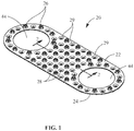
FIG. 1 is a perspective view of an illustrative embodiment of an insert according to the present invention. -
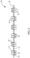
FIG. 2 is an enlarged cross-sectional view showing several of the projections of the insert taken along line 2-2 ofFIG. 1 . -
FIG. 3 is an exploded perspective view of the insert positioned between a terminal and a mating surface. -
FIG. 4 is a perspective view of the insert, terminal and mating surface ofFIG. 3 shown in the fully assembled position. -
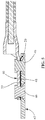
FIG. 5 is a cross-sectional view of the assembly taken along the longitudinal axis of the insert. - An embodiment is directed to an insert which can be used with aluminum terminals which are intended for use with composite structure aircrafts. In one embodiment, the insert is a stamped screen which provides for low bond resistance between the terminals and the shell of the aircraft.
- The present invention will be described more fully hereinafter with reference to the accompanying drawings, in which illustrative embodiments of the invention are shown. In the drawings, the relative sizes of regions or features may be exaggerated for clarity. This invention may, however, be embodied in many different forms and should not be construed as limited to the embodiments set forth herein; rather, these embodiments are provided so that this disclosure will be thorough and complete, and will fully convey the scope of the claimed invention to those skilled in the art.
- It will be understood that spatially relative terms, such as "top", "upper", "lower" and the like, may be used herein for ease of description to describe one element's or feature's relationship to another element(s) or feature(s) as illustrated in the figures. It will be understood that the spatially relative terms are intended to encompass different orientations of the device in use or operation in addition to the orientation depicted in the figures. For example, if the device in the figures is turned over, elements described as "over" other elements or features would then be oriented "under" the other elements or features. Thus, the exemplary term "over" can encompass both an orientation of over and under. The device may be otherwise oriented (rotated 90 degrees or at other orientations) and the spatially relative descriptors used herein interpreted accordingly.
- The present invention is directed to a conductive insert which provides a stable, low resistance electrically conductive path between conductive materials. In particular, the invention is directed to an insert or screen which cooperates with light weight material, such as aluminum, to shear the aluminum oxide present on the surface, thereby eliminating the need for inhibitor greases to be applied to the aluminum.
- As shown in
FIGS. 1 and2 , an illustrative embodiment of aninsert 20 is shown.Insert 20 is provided with afirst surface 22 and an oppositely facingsecond surface 24. In the embodiment shown, the insert is made from a conductive material which has a conductivity equal to or higher than the conductivity of aluminum thereby providing a low bond resistance between low conductive materials. Monel is one example of such a material, however, other materials can be used without departing from the scope of the invention. In the embodiment shown, theinsert 20 has a thickness of between about 0.152 mm (0.006 inches) to about 0.305 mm (0.012 inches), above about 0.152 mm (0.006 inches), below about 0.305 mm (0.012 inches), about 0.152 mm (0.006 inches), about 0.178 mm (0.007 inches), about 0.203 mm (0.008 inches), about 0.229 mm (0.009 inches), about 0.254 mm (0.010 inches), about 0.279 mm (0.011 inches), about 0.305 mm (0.012 inches), or any combination thereof. However, other dimensions may be used without departing from the scope of the claimed invention. In addition, other electrically conducting materials can be used, such as, but not limited to, copper or copper alloys. The type of material is dependent upon the application. In the embodiment shown, the insert is made from aluminum or an aluminum alloy as the insert is used to electrically connect an aluminum terminal to an aluminum substrate or surface, as will be more fully described. Although an essentially flat, planar configuration is shown, other suitable configurations may be readily employed without departing from the scope of the claimed invention. - A plurality of piercing means such as barbs or
projections first surface 22 and thesecond surface 24.Projections 26 are aligned in similarly facing disposition extending from thefirst surface 22 in a direction away from thesecond surface 24. Theprojections 28 are aligned in similarly facing disposition extending from thesecond surface 24 in a direction away from thefirst surface 22. Theprojections 26 are spaced from, and extend in essentially the opposed direction, of theprojections 28. - The
projections respective surfaces insert 20. Theprojections insert 20 wherein theprojections insert 20. Theprojections projections entire surface insert 20, the arrangement may be appropriately altered or modified wherein saidprojections surfaces insert 20. - The
projections insert 20, such as, but not limited to, lancing, skiving, punching, or stamping, in either one or more appropriate operations, to obtain the desired configuration of theprojections projections openings 29 extending through the insert between thefirst surface 22 and thesecond surface 24. Each opening 29 hasprojections more projections opening 29. - As best illustrated in
FIG. 1 , each opening 29 has eitherprojections 26 extending therefrom and proximate thereto orprojections 28 extending therefrom and proximate thereto. Also in the embodiment shown, anopening 29 which hasprojections 26 extending therefrom is surrounded byopenings 29 which hasprojections 28 extending therefrom. Similarly, anopening 29 which hasprojections 28 extending therefrom is surrounded byopenings 29 which hasprojections 26 extending therefrom. This allowsopenings 29 withprojections 26 to alternate withopenings 29 withprojections 28 across the entirefirst surface 22 andsecond surface 24 of theinsert 20. - As shown in greater detail in
FIG. 2 , eachprojection triangular member 30 having a fixedbase 32 and afree end 34. The fixed base is attached to arespective surface free end 34 extends from arespective surface respective surface free end 34 is in the form of a sharp edge orpoint 36 which is formed by two sides of thetriangular member 30. The sharp edges 36 ofprojections 28 serve to provide a piercing surface adequately proportioned to enable theprojections 28 to penetrate any sealants used on the mating terminal and/or the mating surface which are used to environmentally seal the components. In addition,sharp edges 36 ofprojections 28 serve to provide a piercing surface adequately proportioned to enable theprojections 28 to penetrate any oxides which may be present on the mating terminal and/or the mating surface. - The particular shape of
projections projections projections projections - Referring to
FIGS. 3 through 5 , theinsert 20 is shown engaged between a terminal 40 and amating surface 42. In the embodiment shown, the terminal 40 is made from aluminum or an aluminum alloy. However, other electrically conducting materials can be used, such as, but not limited to, copper or copper alloys. The type of material is dependent upon the application. In the embodiment shown, the mating substrate, panel orsurface 42 is a surface of an aircraft structure which is made from aluminum or an aluminum alloy. However, other applications and other electrically conducting materials can be used, such as, but not limited to, copper or copper alloys. The type of material is dependent upon the application. - The terminal 40 may be, but is not limited to, a sealed aluminum terminal sold by TE Connectivity. Such a terminal provides a reliable and stable electro-mechanical "dry sealed crimp" for both copper and aluminum stranded wire. When such terminals are crimped to aluminum wire, the wire's conductor material is extruded through the perforations of a terminal insert. This extrusion shears the aluminum oxide on the wire strands and provides intimate contact between the terminal and wire conductor, thus eliminating the need for inhibitor greases (i.e. "wet crimp"). The reduction in area achieved during crimping is such that cold welds are formed between both the terminal and wire conductor and the wire strands themselves.
- In use, the
insert 20 is positioned between the terminal 40 and thesurface 42. Mountingopenings 44, which extend through theinsert 20, cooperate with mounting hardware orfasteners 46, such as, but not limited to, rivets, screws, nuts and bolts or their equivalent, to maintain theinsert 20 in position relative to the terminal 40 and relative to thesurface 42. The mountinghardware 46 is deformed or tightened causing the terminal 40 to move toward thesurface 42. As this occurs, theinsert 20 is subjected to a compressive force, causing theprojections 26 which extend from thefirst surface 22 to contact asurface 48 of theterminal lug 50 of the terminal 40. As this occurs, theedges 36 of the free ends 34 of theprojections 26 penetrate any sealants used or oxides present on thesurface 48 of the terminal 40. In addition, as theinsert 20 is subjected to a compressive force, theprojections 28 which extend from thesecond surface 24 are forced to contact thesurface 42. As this occurs, theedges 36 of the free ends 34 of theprojections 28 penetrate any sealants used or oxides present on thesurface 42. - As the
projections edges 36 of theprojections insert 20. This allows theedges 36 of the projections to move transversely to the motion of compressions, allowing theprojections surface 48 of the terminal 40 and thesurface 42, thereby enhancing the ability of theprojections insert 20 and thesurface 42. Consequently, as the insert is conductive, a positive electrical connection is effected between the terminal 40 and thesurface 42. The degree of penetration and wiping action of theprojections projections 28, including, but not limited to, the shape of theedges 36. The degree of penetration and wiping action of theprojections insert 20. - The use of the
insert 20 allows the electrical path established between the terminal 40 and the surface orsubstrate 42 to be maintained at a stable, low resistance bond for the life of the installation. This electrical path requires minimum preparation during the terminal installation procedure, or during a maintenance check once in service. In addition, a standard torque wrench, or other readily accessible hand tool, is the only tool that is required to install the terminal lug on, or to remove the terminal lug from, the surface or substrate to which it is attached, - In one embodiment, the
surface 48 of theterminal lug 50 and thesurfaces insert 20 shall be flat within ± 0.127 mm (5 mils), so that the lowest possible bond path resistance can be achieved when theterminal lug 50 is attached to thesurface 42 by means of theinsert 20. - In one embodiment, the terminal lugs 50 are attached to the
surface 42 by two mountingfasteners 46, although other configurations and number of fasteners can be used. - As the terminals lugs 50, insert 20 and
surface 42 are made from similar material, neither the terminal lugs nor the inserts exhibit any evidence of peeling, cracks, fissures, corrosion, blistering, peeling or separation of plating that would adversely affect the electrical and mechanical performance of the assembly.
Claims (8)
- A conductive insert (20) which provides a low resistance bond between low conductive materials, the insert (20) comprising:a first surface (22) and an oppositely facing second surface (24);a plurality of first openings (29) extending between the first surface (22) and the second surface (24), and a plurality of second openings (29) extending between the first surface (22) and the second surface (24);a plurality of first projections (26) extending from the first surface (22) in a direction away from the second surface (24); anda plurality of second projections (28) extending from the second surface (24) in a direction away from the first surface (22),wherein each first projection (26) and each second projection (28) comprises essentially a triangular member (30) having a fixed base (32) and a free end (34), the free end (34) of each first projection (26) and the free end (34) of each second projection (28) being in the form of a sharp edge point which is formed by two sides of the triangular member (30), characterized in thatthe plurality of first projections (26) are proximate each of the respective first openings (29); andthe plurality of second projections (28) are proximate each of the respective second openings (29),wherein the free end (34) of each first projection (26) extends from said first surface (22) at an angle essentially normal to the first surface (22), and the free end (34) of each second projection (28) extends from said second surface (24) at an angle essentially normal to the second surface (24), the projections (26, 28) being compressible so that the edges (36) of the projections (26, 28) are moveable in a direction which is essentially parallel to a longitudinal axis of the insert (20).
- The conductive insert as recited in claim 1, wherein three or more first projections (26) are provided proximate the first openings (29), and three or more second projections (28) are provided proximate the second openings (29).
- The conductive insert as recited in claim 1, wherein the respective first openings (29) are surrounded by respective second openings (29), whereby the first openings (29) with the first projections (26) extending from the first surface (22) alternate with the second openings (29) with the second projections (28) extending from the second surface (24), the first and second openings alternating across the entire first surface (22) and the entire second surface (24).
- The conductive insert as recited in claim 1, wherein the insert (20) is made from conductive material which has a conductivity equal to or higher than the conductivity of aluminum.
- The conductive insert as recited in claim 1, wherein the openings (29) are selectively staggered.
- The conductive insert as recited in claim 1, wherein the first projections (26) and the second projections (28) are disposed in a patterned relationship.
- The conductive insert as recited in claim 1, wherein the plurality of openings (29) are disposed along substantially the entire first surface (22) and the entire second surface (24).
- The conductive insert as recited in claim 1, wherein at least one mounting opening (44) extends through the first surface (22) and the second surface (24) of the insert (20), the mounting opening (44) configured to cooperate with mounting hardware (46).
Applications Claiming Priority (2)
| Application Number | Priority Date | Filing Date | Title |
|---|---|---|---|
| US13/964,721 US9653194B2 (en) | 2013-08-12 | 2013-08-12 | Low resistance insert |
| PCT/US2014/049328 WO2015023451A1 (en) | 2013-08-12 | 2014-08-01 | Low resistance insert |
Publications (2)
| Publication Number | Publication Date |
|---|---|
| EP3033807A1 EP3033807A1 (en) | 2016-06-22 |
| EP3033807B1 true EP3033807B1 (en) | 2018-01-31 |
Family
ID=51483647
Family Applications (1)
| Application Number | Title | Priority Date | Filing Date |
|---|---|---|---|
| EP14758719.0A Active EP3033807B1 (en) | 2013-08-12 | 2014-08-01 | Low resistance insert |
Country Status (6)
| Country | Link |
|---|---|
| US (1) | US9653194B2 (en) |
| EP (1) | EP3033807B1 (en) |
| JP (1) | JP6457519B2 (en) |
| CN (1) | CN105453341B (en) |
| BR (1) | BR112016003036B1 (en) |
| WO (1) | WO2015023451A1 (en) |
Families Citing this family (11)
| Publication number | Priority date | Publication date | Assignee | Title |
|---|---|---|---|---|
| CN106660264A (en) * | 2014-07-25 | 2017-05-10 | 泰科电子瑞侃有限责任公司 | Electrical cable splice and method for connecting power cables |
| DE102015220661A1 (en) * | 2015-10-22 | 2017-04-27 | Te Connectivity Germany Gmbh | Shielding element for a connector and housing arrangement comprising a shielding element |
| CN105261844A (en) * | 2015-11-11 | 2016-01-20 | 何亮 | A filling member at a connecting portion of a plane conductor |
| SE539503C2 (en) * | 2015-11-24 | 2017-10-03 | Northcone Ab | A grounding attachment and a pole provided with such a grounding attachment |
| US20170170579A1 (en) * | 2015-12-09 | 2017-06-15 | Hubbell Incorporated | Bonding clamp |
| US20190273351A1 (en) * | 2018-03-02 | 2019-09-05 | Mersen Usa Newburyport-Ma, Llc | Electrical connector |
| WO2020092250A1 (en) | 2018-10-29 | 2020-05-07 | Hubbell Incorporated | Bonding washer |
| DE102020108669B3 (en) | 2020-03-30 | 2021-04-29 | Auto-Kabel Management Gmbh | Connection arrangement and method for connecting a connection arrangement to a component |
| KR102930129B1 (en) * | 2020-07-28 | 2026-02-25 | 주식회사 엘지에너지솔루션 | Base metal assembly for mechanical and electrical connecting, and method for riveting the same |
| JP7436430B2 (en) * | 2021-07-20 | 2024-02-21 | 矢崎総業株式会社 | Terminals, wires with terminals, and connection structures |
| JP2025162882A (en) * | 2024-04-16 | 2025-10-28 | 株式会社オートネットワーク技術研究所 | Terminal connection structure and aluminum electric wire with terminal |
Family Cites Families (52)
| Publication number | Priority date | Publication date | Assignee | Title |
|---|---|---|---|---|
| US491173A (en) * | 1893-02-07 | Nut-lock | ||
| US662003A (en) * | 1900-06-09 | 1900-11-20 | Alfred Lamm | Washer. |
| US2069402A (en) * | 1935-06-29 | 1937-02-02 | Eaton Mfg Co | Lock washer |
| US2796457A (en) * | 1952-06-23 | 1957-06-18 | Walter E Stinger | R-f gasket for radio interference attenuation |
| US2946039A (en) * | 1957-11-06 | 1960-07-19 | Durakool Inc | Electrical terminal |
| US3247316A (en) * | 1964-04-22 | 1966-04-19 | Amp Inc | Electrical connector for terminating aluminum foil |
| NL7003475A (en) * | 1969-03-28 | 1970-09-30 | ||
| US3549786A (en) * | 1969-04-04 | 1970-12-22 | Thomas & Betts Corp | Insulation piercing connector |
| US3626357A (en) * | 1970-09-02 | 1971-12-07 | Colin David Kindell | Electrical connecting washer |
| BE787907A (en) * | 1971-08-23 | 1973-02-23 | Thomas & Betts Corp | FLAT ELEMENT CONNECTOR |
| BE793917A (en) * | 1971-11-02 | 1973-07-11 | Thomas & Betts Corp | CONNECTOR |
| BE794320A (en) * | 1972-01-19 | 1973-07-19 | Thomas & Betts Corp | INSULATION AND OXIDE DRILLING CONTACT MEANS |
| US3881799A (en) * | 1972-09-11 | 1975-05-06 | George H Elliott | Resilient multi-micro point metallic junction |
| US3914490A (en) | 1973-08-01 | 1975-10-21 | Dana Corp | Ceramic fiber gasket |
| US3895851A (en) | 1973-08-23 | 1975-07-22 | Amp Inc | Brittle-surfaced connector |
| US4060301A (en) * | 1974-03-12 | 1977-11-29 | Beatty Albert W | Electrical connector for transmission line insulators |
| US4009925A (en) * | 1974-03-27 | 1977-03-01 | Maschinenfabrik Augsburg-Nurnberg Ag | Detachable connection between two electric conductors |
| US4023882A (en) * | 1974-04-25 | 1977-05-17 | Borge Hugo Pettersson | Electrical connector device securable to metal member |
| NO141299C (en) * | 1974-10-10 | 1980-02-06 | Siemens Ag | PACKING FOR HIGH-FREQUENCY CONNECTION OF RELIABLE METAL SHIELDING ELEMENTS |
| US4080033A (en) * | 1976-03-24 | 1978-03-21 | Multilam Corporation | Louvered electrical connector and method of making same |
| US4182541A (en) * | 1977-12-27 | 1980-01-08 | Galaini James L | Burglar alarm foil block |
| US4511200A (en) * | 1982-12-02 | 1985-04-16 | Belokin Jr Paul | Electrical connector having handle-mounted bifurcated resilient pin-engaging electrical plate |
| US4687263A (en) | 1983-03-10 | 1987-08-18 | Amp Incorporated | Shielding kit for electrical connectors terminating multiconductor 360 degree shielded cable |
| USD287240S (en) * | 1983-03-14 | 1986-12-16 | Thomas & Betts Corporation | Electrical connector including insulation displacing contacts |
| US4550965A (en) * | 1983-04-25 | 1985-11-05 | Thomas & Betts Corporation | Connector assembly for insulated cable |
| US4691972A (en) * | 1985-03-01 | 1987-09-08 | Rogers Corporation | Solderless connection apparatus |
| US5137461A (en) * | 1988-06-21 | 1992-08-11 | International Business Machines Corporation | Separable electrical connection technology |
| US4875876A (en) * | 1988-08-31 | 1989-10-24 | Thomas & Betts Corporation | Electrical connector for overlapped conductors |
| US4943247A (en) * | 1989-05-31 | 1990-07-24 | Amp Incorporated | Annular electrical terminal |
| US5118299A (en) * | 1990-05-07 | 1992-06-02 | International Business Machines Corporation | Cone electrical contact |
| US5172473A (en) * | 1990-05-07 | 1992-12-22 | International Business Machines Corporation | Method of making cone electrical contact |
| US5105537A (en) * | 1990-10-12 | 1992-04-21 | International Business Machines Corporation | Method for making a detachable electrical contact |
| US6719293B1 (en) | 1992-08-19 | 2004-04-13 | The Boeing Company | Corrosion resistant gasket for aircraft |
| US6454276B2 (en) | 1992-08-19 | 2002-09-24 | The Boeing Company | Corrosion resistant gasket for aircraft |
| US6454267B1 (en) | 1992-08-19 | 2002-09-24 | The Boeing Company | Corrosion resistant gasket for aircraft |
| US5791654A (en) | 1992-08-19 | 1998-08-11 | The Boeing Company | Corrosion resistant gasket in combination with aircraft antenna |
| FR2704101B3 (en) * | 1993-04-15 | 1995-03-03 | Simel | Conductive seal for mechanical tightening electrical connectors. |
| US5865638A (en) * | 1995-12-21 | 1999-02-02 | Alcoa Fujikura Ltd. | Electrical connector |
| JP3502776B2 (en) * | 1998-11-26 | 2004-03-02 | 新光電気工業株式会社 | Metal foil with bump, circuit board, and semiconductor device using the same |
| US6186799B1 (en) * | 1999-10-21 | 2001-02-13 | Fci Usa, Inc. | Compression grounding connector for rail and structural steel |
| US6595785B2 (en) * | 2001-10-05 | 2003-07-22 | Delphi Technologies, Inc. | Bump contact force concentration system and method |
| EP1690031A2 (en) | 2003-11-25 | 2006-08-16 | Garlock Sealing Technologies LLC | Corrugated gasket core with profiled surface cross reference to related applications |
| WO2005057056A2 (en) | 2003-12-05 | 2005-06-23 | Garlock Sealing Technologies, Llc | Gasket of non-rounded shape with installation aids |
| US8092129B2 (en) * | 2006-04-21 | 2012-01-10 | Hubbell Incorporated | Bonding washer |
| US8393068B2 (en) | 2007-11-06 | 2013-03-12 | The Boeing Company | Method and apparatus for assembling composite structures |
| DE102010005841B4 (en) * | 2010-01-26 | 2011-12-08 | Auto-Kabel Managementgesellschaft Mbh | Cable lug with cup-shaped formation and fastening device |
| US8507804B2 (en) * | 2010-02-22 | 2013-08-13 | Tyco Electronics Corporation | Electrical connector with solder columns |
| JP2012009411A (en) * | 2010-05-24 | 2012-01-12 | Japan Aviation Electronics Industry Ltd | Conductor connection washer, connection mechanism using it and method of manufacturing conductor connection washer |
| US9091461B2 (en) * | 2011-04-27 | 2015-07-28 | Blue Sunny Skies Llc | Grounding system for photovoltaic arrays |
| EP2592914B1 (en) * | 2011-11-14 | 2015-05-06 | Continental Automotive GmbH | Clamping element |
| CA2816502A1 (en) * | 2012-05-24 | 2013-11-24 | Cablofil, Inc. | Bonding clip |
| US9643230B2 (en) * | 2013-03-14 | 2017-05-09 | A.K. Stamping Company, Inc. | Grounding spacer |
-
2013
- 2013-08-12 US US13/964,721 patent/US9653194B2/en active Active
-
2014
- 2014-08-01 JP JP2016533343A patent/JP6457519B2/en not_active Expired - Fee Related
- 2014-08-01 BR BR112016003036-2A patent/BR112016003036B1/en active IP Right Grant
- 2014-08-01 EP EP14758719.0A patent/EP3033807B1/en active Active
- 2014-08-01 WO PCT/US2014/049328 patent/WO2015023451A1/en not_active Ceased
- 2014-08-01 CN CN201480044633.0A patent/CN105453341B/en active Active
Also Published As
| Publication number | Publication date |
|---|---|
| CN105453341A (en) | 2016-03-30 |
| BR112016003036B1 (en) | 2021-11-09 |
| JP6457519B2 (en) | 2019-01-23 |
| US9653194B2 (en) | 2017-05-16 |
| US20150041211A1 (en) | 2015-02-12 |
| CN105453341B (en) | 2018-05-18 |
| EP3033807A1 (en) | 2016-06-22 |
| WO2015023451A1 (en) | 2015-02-19 |
| BR112016003036A2 (en) | 2017-09-12 |
| JP2016527695A (en) | 2016-09-08 |
Similar Documents
| Publication | Publication Date | Title |
|---|---|---|
| US9653194B2 (en) | Low resistance insert | |
| CN102598361B (en) | Battery connector | |
| JP4670958B2 (en) | Electrode and battery device manufacturing method | |
| CA3115002C (en) | Connectors for flexible busbar and methods of connecting | |
| US20120028494A1 (en) | Terminal connector and electric wire with terminal connector | |
| US20150180189A1 (en) | Air-Tight and Water-Tight Electrical Bonding Device | |
| CN107667451B (en) | Cable crimping connection system and assembly method thereof, fastening sleeve | |
| US20120205423A1 (en) | Wire end processing method | |
| US7547228B1 (en) | Joining means for device components | |
| EP4391238A1 (en) | Plug terminal, plug structure and motor vehicle | |
| EP0883210A2 (en) | Terminal assembling structure and method | |
| US5915758A (en) | Bridge for low resistance electrical connections and method of using same | |
| CN103515740A (en) | Surface structure of conducting element, and washer and crimp terminal with same | |
| US20080252158A1 (en) | Torque resistant terminal block assembly | |
| CN102656720A (en) | Terminal for accumulator cells | |
| KR20160040700A (en) | Aluminum electric wire connection structure | |
| JP2010010000A (en) | Terminal metal fixture and wire with terminal | |
| US20180048080A1 (en) | Terminal attached wire | |
| US10050356B2 (en) | High temperature vibration resistant solderless electrical connections for planar surfaces | |
| US20250098112A1 (en) | Conductor member with cooling structure | |
| US20250183559A1 (en) | Insulation piercing tap connectorsfor electrical conductors | |
| RU73547U1 (en) | ELECTRIC CONTACT CLAMP OF TAPE CURRENT CONDUCTORS | |
| EP2792023A1 (en) | Electrically conductive pin connection | |
| CN224082711U (en) | Photovoltaic grounding device | |
| US20070044422A1 (en) | Conformable interface device for improved electrical joint |
Legal Events
| Date | Code | Title | Description |
|---|---|---|---|
| PUAI | Public reference made under article 153(3) epc to a published international application that has entered the european phase |
Free format text: ORIGINAL CODE: 0009012 |
|
| 17P | Request for examination filed |
Effective date: 20160307 |
|
| AK | Designated contracting states |
Kind code of ref document: A1 Designated state(s): AL AT BE BG CH CY CZ DE DK EE ES FI FR GB GR HR HU IE IS IT LI LT LU LV MC MK MT NL NO PL PT RO RS SE SI SK SM TR |
|
| AX | Request for extension of the european patent |
Extension state: BA ME |
|
| DAX | Request for extension of the european patent (deleted) | ||
| RAP1 | Party data changed (applicant data changed or rights of an application transferred) |
Owner name: TE CONNECTIVITY CORPORATION |
|
| 17Q | First examination report despatched |
Effective date: 20170215 |
|
| GRAP | Despatch of communication of intention to grant a patent |
Free format text: ORIGINAL CODE: EPIDOSNIGR1 |
|
| RIC1 | Information provided on ipc code assigned before grant |
Ipc: H01R 4/26 20060101ALI20170921BHEP Ipc: H01R 4/06 20060101AFI20170921BHEP Ipc: H01B 1/02 20060101ALI20170921BHEP Ipc: F16J 15/06 20060101ALI20170921BHEP Ipc: H01R 11/12 20060101ALI20170921BHEP Ipc: H01R 4/62 20060101ALI20170921BHEP Ipc: H01R 13/533 20060101ALI20170921BHEP Ipc: H01B 5/00 20060101ALI20170921BHEP Ipc: H01R 4/34 20060101ALI20170921BHEP Ipc: B64D 45/02 20060101ALN20170921BHEP |
|
| INTG | Intention to grant announced |
Effective date: 20171009 |
|
| GRAS | Grant fee paid |
Free format text: ORIGINAL CODE: EPIDOSNIGR3 |
|
| GRAA | (expected) grant |
Free format text: ORIGINAL CODE: 0009210 |
|
| AK | Designated contracting states |
Kind code of ref document: B1 Designated state(s): AL AT BE BG CH CY CZ DE DK EE ES FI FR GB GR HR HU IE IS IT LI LT LU LV MC MK MT NL NO PL PT RO RS SE SI SK SM TR |
|
| REG | Reference to a national code |
Ref country code: GB Ref legal event code: FG4D Ref country code: CH Ref legal event code: EP |
|
| REG | Reference to a national code |
Ref country code: AT Ref legal event code: REF Ref document number: 968148 Country of ref document: AT Kind code of ref document: T Effective date: 20180215 |
|
| REG | Reference to a national code |
Ref country code: IE Ref legal event code: FG4D |
|
| REG | Reference to a national code |
Ref country code: DE Ref legal event code: R096 Ref document number: 602014020446 Country of ref document: DE |
|
| REG | Reference to a national code |
Ref country code: NL Ref legal event code: MP Effective date: 20180131 |
|
| REG | Reference to a national code |
Ref country code: LT Ref legal event code: MG4D |
|
| REG | Reference to a national code |
Ref country code: FR Ref legal event code: PLFP Year of fee payment: 5 |
|
| REG | Reference to a national code |
Ref country code: AT Ref legal event code: MK05 Ref document number: 968148 Country of ref document: AT Kind code of ref document: T Effective date: 20180131 |
|
| PG25 | Lapsed in a contracting state [announced via postgrant information from national office to epo] |
Ref country code: HR Free format text: LAPSE BECAUSE OF FAILURE TO SUBMIT A TRANSLATION OF THE DESCRIPTION OR TO PAY THE FEE WITHIN THE PRESCRIBED TIME-LIMIT Effective date: 20180131 Ref country code: NL Free format text: LAPSE BECAUSE OF FAILURE TO SUBMIT A TRANSLATION OF THE DESCRIPTION OR TO PAY THE FEE WITHIN THE PRESCRIBED TIME-LIMIT Effective date: 20180131 Ref country code: NO Free format text: LAPSE BECAUSE OF FAILURE TO SUBMIT A TRANSLATION OF THE DESCRIPTION OR TO PAY THE FEE WITHIN THE PRESCRIBED TIME-LIMIT Effective date: 20180430 Ref country code: LT Free format text: LAPSE BECAUSE OF FAILURE TO SUBMIT A TRANSLATION OF THE DESCRIPTION OR TO PAY THE FEE WITHIN THE PRESCRIBED TIME-LIMIT Effective date: 20180131 Ref country code: ES Free format text: LAPSE BECAUSE OF FAILURE TO SUBMIT A TRANSLATION OF THE DESCRIPTION OR TO PAY THE FEE WITHIN THE PRESCRIBED TIME-LIMIT Effective date: 20180131 Ref country code: FI Free format text: LAPSE BECAUSE OF FAILURE TO SUBMIT A TRANSLATION OF THE DESCRIPTION OR TO PAY THE FEE WITHIN THE PRESCRIBED TIME-LIMIT Effective date: 20180131 |
|
| PG25 | Lapsed in a contracting state [announced via postgrant information from national office to epo] |
Ref country code: PL Free format text: LAPSE BECAUSE OF FAILURE TO SUBMIT A TRANSLATION OF THE DESCRIPTION OR TO PAY THE FEE WITHIN THE PRESCRIBED TIME-LIMIT Effective date: 20180131 Ref country code: GR Free format text: LAPSE BECAUSE OF FAILURE TO SUBMIT A TRANSLATION OF THE DESCRIPTION OR TO PAY THE FEE WITHIN THE PRESCRIBED TIME-LIMIT Effective date: 20180501 Ref country code: AT Free format text: LAPSE BECAUSE OF FAILURE TO SUBMIT A TRANSLATION OF THE DESCRIPTION OR TO PAY THE FEE WITHIN THE PRESCRIBED TIME-LIMIT Effective date: 20180131 Ref country code: BG Free format text: LAPSE BECAUSE OF FAILURE TO SUBMIT A TRANSLATION OF THE DESCRIPTION OR TO PAY THE FEE WITHIN THE PRESCRIBED TIME-LIMIT Effective date: 20180430 Ref country code: SE Free format text: LAPSE BECAUSE OF FAILURE TO SUBMIT A TRANSLATION OF THE DESCRIPTION OR TO PAY THE FEE WITHIN THE PRESCRIBED TIME-LIMIT Effective date: 20180131 Ref country code: LV Free format text: LAPSE BECAUSE OF FAILURE TO SUBMIT A TRANSLATION OF THE DESCRIPTION OR TO PAY THE FEE WITHIN THE PRESCRIBED TIME-LIMIT Effective date: 20180131 Ref country code: IS Free format text: LAPSE BECAUSE OF FAILURE TO SUBMIT A TRANSLATION OF THE DESCRIPTION OR TO PAY THE FEE WITHIN THE PRESCRIBED TIME-LIMIT Effective date: 20180531 Ref country code: RS Free format text: LAPSE BECAUSE OF FAILURE TO SUBMIT A TRANSLATION OF THE DESCRIPTION OR TO PAY THE FEE WITHIN THE PRESCRIBED TIME-LIMIT Effective date: 20180131 |
|
| PG25 | Lapsed in a contracting state [announced via postgrant information from national office to epo] |
Ref country code: AL Free format text: LAPSE BECAUSE OF FAILURE TO SUBMIT A TRANSLATION OF THE DESCRIPTION OR TO PAY THE FEE WITHIN THE PRESCRIBED TIME-LIMIT Effective date: 20180131 Ref country code: IT Free format text: LAPSE BECAUSE OF FAILURE TO SUBMIT A TRANSLATION OF THE DESCRIPTION OR TO PAY THE FEE WITHIN THE PRESCRIBED TIME-LIMIT Effective date: 20180131 Ref country code: RO Free format text: LAPSE BECAUSE OF FAILURE TO SUBMIT A TRANSLATION OF THE DESCRIPTION OR TO PAY THE FEE WITHIN THE PRESCRIBED TIME-LIMIT Effective date: 20180131 Ref country code: EE Free format text: LAPSE BECAUSE OF FAILURE TO SUBMIT A TRANSLATION OF THE DESCRIPTION OR TO PAY THE FEE WITHIN THE PRESCRIBED TIME-LIMIT Effective date: 20180131 |
|
| REG | Reference to a national code |
Ref country code: DE Ref legal event code: R097 Ref document number: 602014020446 Country of ref document: DE |
|
| PG25 | Lapsed in a contracting state [announced via postgrant information from national office to epo] |
Ref country code: CZ Free format text: LAPSE BECAUSE OF FAILURE TO SUBMIT A TRANSLATION OF THE DESCRIPTION OR TO PAY THE FEE WITHIN THE PRESCRIBED TIME-LIMIT Effective date: 20180131 Ref country code: SM Free format text: LAPSE BECAUSE OF FAILURE TO SUBMIT A TRANSLATION OF THE DESCRIPTION OR TO PAY THE FEE WITHIN THE PRESCRIBED TIME-LIMIT Effective date: 20180131 Ref country code: DK Free format text: LAPSE BECAUSE OF FAILURE TO SUBMIT A TRANSLATION OF THE DESCRIPTION OR TO PAY THE FEE WITHIN THE PRESCRIBED TIME-LIMIT Effective date: 20180131 Ref country code: SK Free format text: LAPSE BECAUSE OF FAILURE TO SUBMIT A TRANSLATION OF THE DESCRIPTION OR TO PAY THE FEE WITHIN THE PRESCRIBED TIME-LIMIT Effective date: 20180131 |
|
| PLBE | No opposition filed within time limit |
Free format text: ORIGINAL CODE: 0009261 |
|
| STAA | Information on the status of an ep patent application or granted ep patent |
Free format text: STATUS: NO OPPOSITION FILED WITHIN TIME LIMIT |
|
| 26N | No opposition filed |
Effective date: 20181102 |
|
| PG25 | Lapsed in a contracting state [announced via postgrant information from national office to epo] |
Ref country code: SI Free format text: LAPSE BECAUSE OF FAILURE TO SUBMIT A TRANSLATION OF THE DESCRIPTION OR TO PAY THE FEE WITHIN THE PRESCRIBED TIME-LIMIT Effective date: 20180131 |
|
| PG25 | Lapsed in a contracting state [announced via postgrant information from national office to epo] |
Ref country code: MC Free format text: LAPSE BECAUSE OF FAILURE TO SUBMIT A TRANSLATION OF THE DESCRIPTION OR TO PAY THE FEE WITHIN THE PRESCRIBED TIME-LIMIT Effective date: 20180131 |
|
| REG | Reference to a national code |
Ref country code: CH Ref legal event code: PL |
|
| PG25 | Lapsed in a contracting state [announced via postgrant information from national office to epo] |
Ref country code: CH Free format text: LAPSE BECAUSE OF NON-PAYMENT OF DUE FEES Effective date: 20180831 Ref country code: LU Free format text: LAPSE BECAUSE OF NON-PAYMENT OF DUE FEES Effective date: 20180801 Ref country code: LI Free format text: LAPSE BECAUSE OF NON-PAYMENT OF DUE FEES Effective date: 20180831 |
|
| REG | Reference to a national code |
Ref country code: BE Ref legal event code: MM Effective date: 20180831 |
|
| REG | Reference to a national code |
Ref country code: IE Ref legal event code: MM4A |
|
| PG25 | Lapsed in a contracting state [announced via postgrant information from national office to epo] |
Ref country code: IE Free format text: LAPSE BECAUSE OF NON-PAYMENT OF DUE FEES Effective date: 20180801 |
|
| PG25 | Lapsed in a contracting state [announced via postgrant information from national office to epo] |
Ref country code: BE Free format text: LAPSE BECAUSE OF NON-PAYMENT OF DUE FEES Effective date: 20180831 |
|
| PG25 | Lapsed in a contracting state [announced via postgrant information from national office to epo] |
Ref country code: MT Free format text: LAPSE BECAUSE OF NON-PAYMENT OF DUE FEES Effective date: 20180801 |
|
| PG25 | Lapsed in a contracting state [announced via postgrant information from national office to epo] |
Ref country code: TR Free format text: LAPSE BECAUSE OF FAILURE TO SUBMIT A TRANSLATION OF THE DESCRIPTION OR TO PAY THE FEE WITHIN THE PRESCRIBED TIME-LIMIT Effective date: 20180131 |
|
| PG25 | Lapsed in a contracting state [announced via postgrant information from national office to epo] |
Ref country code: PT Free format text: LAPSE BECAUSE OF FAILURE TO SUBMIT A TRANSLATION OF THE DESCRIPTION OR TO PAY THE FEE WITHIN THE PRESCRIBED TIME-LIMIT Effective date: 20180131 |
|
| PG25 | Lapsed in a contracting state [announced via postgrant information from national office to epo] |
Ref country code: MK Free format text: LAPSE BECAUSE OF NON-PAYMENT OF DUE FEES Effective date: 20180131 Ref country code: HU Free format text: LAPSE BECAUSE OF FAILURE TO SUBMIT A TRANSLATION OF THE DESCRIPTION OR TO PAY THE FEE WITHIN THE PRESCRIBED TIME-LIMIT; INVALID AB INITIO Effective date: 20140801 Ref country code: CY Free format text: LAPSE BECAUSE OF FAILURE TO SUBMIT A TRANSLATION OF THE DESCRIPTION OR TO PAY THE FEE WITHIN THE PRESCRIBED TIME-LIMIT Effective date: 20180131 |
|
| PGFP | Annual fee paid to national office [announced via postgrant information from national office to epo] |
Ref country code: GB Payment date: 20250612 Year of fee payment: 12 |
|
| PGFP | Annual fee paid to national office [announced via postgrant information from national office to epo] |
Ref country code: FR Payment date: 20250610 Year of fee payment: 12 |
|
| REG | Reference to a national code |
Ref country code: GB Ref legal event code: 732E Free format text: REGISTERED BETWEEN 20250731 AND 20250806 |
|
| PGFP | Annual fee paid to national office [announced via postgrant information from national office to epo] |
Ref country code: DE Payment date: 20250604 Year of fee payment: 12 |