EP3033450B1 - Verfahren zum waschen von wäsche in einer wäschewaschmaschine sowie wäschewaschmaschine - Google Patents
Verfahren zum waschen von wäsche in einer wäschewaschmaschine sowie wäschewaschmaschine Download PDFInfo
- Publication number
- EP3033450B1 EP3033450B1 EP13750020.3A EP13750020A EP3033450B1 EP 3033450 B1 EP3033450 B1 EP 3033450B1 EP 13750020 A EP13750020 A EP 13750020A EP 3033450 B1 EP3033450 B1 EP 3033450B1
- Authority
- EP
- European Patent Office
- Prior art keywords
- washing
- laundry
- tub
- drum
- liquid
- Prior art date
- Legal status (The legal status is an assumption and is not a legal conclusion. Google has not performed a legal analysis and makes no representation as to the accuracy of the status listed.)
- Active
Links
- 238000000034 method Methods 0.000 title claims description 75
- 238000010412 laundry washing Methods 0.000 title claims description 73
- XLYOFNOQVPJJNP-UHFFFAOYSA-N water Substances O XLYOFNOQVPJJNP-UHFFFAOYSA-N 0.000 claims description 215
- 238000005406 washing Methods 0.000 claims description 200
- 239000007788 liquid Substances 0.000 claims description 195
- 239000000654 additive Substances 0.000 claims description 98
- 238000002156 mixing Methods 0.000 claims description 94
- 230000000996 additive effect Effects 0.000 claims description 84
- 230000004913 activation Effects 0.000 claims description 57
- 239000003599 detergent Substances 0.000 claims description 27
- 230000003213 activating effect Effects 0.000 claims description 21
- 238000009987 spinning Methods 0.000 claims description 13
- 239000008400 supply water Substances 0.000 claims description 4
- 239000000203 mixture Substances 0.000 description 76
- 238000001994 activation Methods 0.000 description 58
- 239000002979 fabric softener Substances 0.000 description 14
- 238000010438 heat treatment Methods 0.000 description 13
- 238000001914 filtration Methods 0.000 description 12
- 238000011282 treatment Methods 0.000 description 12
- 238000010521 absorption reaction Methods 0.000 description 11
- 238000011012 sanitization Methods 0.000 description 10
- 239000004744 fabric Substances 0.000 description 9
- ZAMOUSCENKQFHK-UHFFFAOYSA-N Chlorine atom Chemical compound [Cl] ZAMOUSCENKQFHK-UHFFFAOYSA-N 0.000 description 8
- 239000000460 chlorine Substances 0.000 description 8
- 229910052801 chlorine Inorganic materials 0.000 description 8
- 238000004078 waterproofing Methods 0.000 description 8
- 239000003795 chemical substances by application Substances 0.000 description 7
- 238000000605 extraction Methods 0.000 description 7
- 230000009471 action Effects 0.000 description 6
- 239000002245 particle Substances 0.000 description 6
- 239000003623 enhancer Substances 0.000 description 5
- 238000001035 drying Methods 0.000 description 4
- 238000011068 loading method Methods 0.000 description 4
- 239000000843 powder Substances 0.000 description 4
- 230000008569 process Effects 0.000 description 4
- 238000010790 dilution Methods 0.000 description 3
- 239000012895 dilution Substances 0.000 description 3
- 238000004090 dissolution Methods 0.000 description 3
- 238000009826 distribution Methods 0.000 description 3
- 238000011049 filling Methods 0.000 description 3
- 239000002304 perfume Substances 0.000 description 3
- 239000004902 Softening Agent Substances 0.000 description 2
- 230000007423 decrease Effects 0.000 description 2
- 239000008240 homogeneous mixture Substances 0.000 description 2
- 239000000243 solution Substances 0.000 description 2
- 238000003860 storage Methods 0.000 description 2
- OYPRJOBELJOOCE-UHFFFAOYSA-N Calcium Chemical compound [Ca] OYPRJOBELJOOCE-UHFFFAOYSA-N 0.000 description 1
- FYYHWMGAXLPEAU-UHFFFAOYSA-N Magnesium Chemical compound [Mg] FYYHWMGAXLPEAU-UHFFFAOYSA-N 0.000 description 1
- 239000006096 absorbing agent Substances 0.000 description 1
- WYTGDNHDOZPMIW-RCBQFDQVSA-N alstonine Natural products C1=CC2=C3C=CC=CC3=NC2=C2N1C[C@H]1[C@H](C)OC=C(C(=O)OC)[C@H]1C2 WYTGDNHDOZPMIW-RCBQFDQVSA-N 0.000 description 1
- 238000010420 art technique Methods 0.000 description 1
- 229910052791 calcium Inorganic materials 0.000 description 1
- 239000011575 calcium Substances 0.000 description 1
- 150000001768 cations Chemical class 0.000 description 1
- 238000004140 cleaning Methods 0.000 description 1
- 230000000295 complement effect Effects 0.000 description 1
- 238000010276 construction Methods 0.000 description 1
- 125000001475 halogen functional group Chemical group 0.000 description 1
- 239000008233 hard water Substances 0.000 description 1
- 230000005923 long-lasting effect Effects 0.000 description 1
- 229910052749 magnesium Inorganic materials 0.000 description 1
- 239000011777 magnesium Substances 0.000 description 1
- 229910052751 metal Inorganic materials 0.000 description 1
- 239000002184 metal Substances 0.000 description 1
- 230000004048 modification Effects 0.000 description 1
- 238000012986 modification Methods 0.000 description 1
- 230000003287 optical effect Effects 0.000 description 1
- 230000003134 recirculating effect Effects 0.000 description 1
- 230000001172 regenerating effect Effects 0.000 description 1
- 230000008929 regeneration Effects 0.000 description 1
- 238000011069 regeneration method Methods 0.000 description 1
- 150000003839 salts Chemical class 0.000 description 1
- 239000007921 spray Substances 0.000 description 1
- 238000009736 wetting Methods 0.000 description 1
Images


Classifications
-
- D—TEXTILES; PAPER
- D06—TREATMENT OF TEXTILES OR THE LIKE; LAUNDERING; FLEXIBLE MATERIALS NOT OTHERWISE PROVIDED FOR
- D06F—LAUNDERING, DRYING, IRONING, PRESSING OR FOLDING TEXTILE ARTICLES
- D06F39/00—Details of washing machines not specific to a single type of machines covered by groups D06F9/00 - D06F27/00
- D06F39/08—Liquid supply or discharge arrangements
- D06F39/083—Liquid discharge or recirculation arrangements
-
- D—TEXTILES; PAPER
- D06—TREATMENT OF TEXTILES OR THE LIKE; LAUNDERING; FLEXIBLE MATERIALS NOT OTHERWISE PROVIDED FOR
- D06F—LAUNDERING, DRYING, IRONING, PRESSING OR FOLDING TEXTILE ARTICLES
- D06F29/00—Combinations of a washing machine with other separate apparatus in a common frame or the like, e.g. with rinsing apparatus
- D06F29/02—Combinations of a washing machine with other separate apparatus in a common frame or the like, e.g. with rinsing apparatus with liquid-extracting apparatus
-
- D—TEXTILES; PAPER
- D06—TREATMENT OF TEXTILES OR THE LIKE; LAUNDERING; FLEXIBLE MATERIALS NOT OTHERWISE PROVIDED FOR
- D06F—LAUNDERING, DRYING, IRONING, PRESSING OR FOLDING TEXTILE ARTICLES
- D06F39/00—Details of washing machines not specific to a single type of machines covered by groups D06F9/00 - D06F27/00
- D06F39/08—Liquid supply or discharge arrangements
- D06F39/088—Liquid supply arrangements
-
- F—MECHANICAL ENGINEERING; LIGHTING; HEATING; WEAPONS; BLASTING
- F03—MACHINES OR ENGINES FOR LIQUIDS; WIND, SPRING, OR WEIGHT MOTORS; PRODUCING MECHANICAL POWER OR A REACTIVE PROPULSIVE THRUST, NOT OTHERWISE PROVIDED FOR
- F03C—POSITIVE-DISPLACEMENT ENGINES DRIVEN BY LIQUIDS
- F03C1/00—Reciprocating-piston liquid engines
- F03C1/02—Reciprocating-piston liquid engines with multiple-cylinders, characterised by the number or arrangement of cylinders
- F03C1/06—Reciprocating-piston liquid engines with multiple-cylinders, characterised by the number or arrangement of cylinders with cylinder axes generally coaxial with, or parallel or inclined to, main shaft axis
- F03C1/0636—Reciprocating-piston liquid engines with multiple-cylinders, characterised by the number or arrangement of cylinders with cylinder axes generally coaxial with, or parallel or inclined to, main shaft axis having rotary cylinder block
- F03C1/0644—Component parts
- F03C1/0668—Swash or actuated plate
- F03C1/0671—Swash or actuated plate bearing means or driven axis bearing means
-
- F—MECHANICAL ENGINEERING; LIGHTING; HEATING; WEAPONS; BLASTING
- F04—POSITIVE - DISPLACEMENT MACHINES FOR LIQUIDS; PUMPS FOR LIQUIDS OR ELASTIC FLUIDS
- F04B—POSITIVE-DISPLACEMENT MACHINES FOR LIQUIDS; PUMPS
- F04B1/00—Multi-cylinder machines or pumps characterised by number or arrangement of cylinders
- F04B1/12—Multi-cylinder machines or pumps characterised by number or arrangement of cylinders having cylinder axes coaxial with, or parallel or inclined to, main shaft axis
- F04B1/122—Details or component parts, e.g. valves, sealings or lubrication means
- F04B1/124—Pistons
-
- F—MECHANICAL ENGINEERING; LIGHTING; HEATING; WEAPONS; BLASTING
- F04—POSITIVE - DISPLACEMENT MACHINES FOR LIQUIDS; PUMPS FOR LIQUIDS OR ELASTIC FLUIDS
- F04B—POSITIVE-DISPLACEMENT MACHINES FOR LIQUIDS; PUMPS
- F04B1/00—Multi-cylinder machines or pumps characterised by number or arrangement of cylinders
- F04B1/12—Multi-cylinder machines or pumps characterised by number or arrangement of cylinders having cylinder axes coaxial with, or parallel or inclined to, main shaft axis
- F04B1/20—Multi-cylinder machines or pumps characterised by number or arrangement of cylinders having cylinder axes coaxial with, or parallel or inclined to, main shaft axis having rotary cylinder block
- F04B1/2014—Details or component parts
- F04B1/2078—Swash plates
- F04B1/2085—Bearings for swash plates or driving axles
-
- F—MECHANICAL ENGINEERING; LIGHTING; HEATING; WEAPONS; BLASTING
- F04—POSITIVE - DISPLACEMENT MACHINES FOR LIQUIDS; PUMPS FOR LIQUIDS OR ELASTIC FLUIDS
- F04B—POSITIVE-DISPLACEMENT MACHINES FOR LIQUIDS; PUMPS
- F04B1/00—Multi-cylinder machines or pumps characterised by number or arrangement of cylinders
- F04B1/12—Multi-cylinder machines or pumps characterised by number or arrangement of cylinders having cylinder axes coaxial with, or parallel or inclined to, main shaft axis
- F04B1/26—Control
- F04B1/30—Control of machines or pumps with rotary cylinder blocks
- F04B1/32—Control of machines or pumps with rotary cylinder blocks by varying the relative positions of a swash plate and a cylinder block
- F04B1/324—Control of machines or pumps with rotary cylinder blocks by varying the relative positions of a swash plate and a cylinder block by changing the inclination of the swash plate
-
- F—MECHANICAL ENGINEERING; LIGHTING; HEATING; WEAPONS; BLASTING
- F04—POSITIVE - DISPLACEMENT MACHINES FOR LIQUIDS; PUMPS FOR LIQUIDS OR ELASTIC FLUIDS
- F04B—POSITIVE-DISPLACEMENT MACHINES FOR LIQUIDS; PUMPS
- F04B53/00—Component parts, details or accessories not provided for in, or of interest apart from, groups F04B1/00 - F04B23/00 or F04B39/00 - F04B47/00
- F04B53/22—Arrangements for enabling ready assembly or disassembly
-
- D—TEXTILES; PAPER
- D06—TREATMENT OF TEXTILES OR THE LIKE; LAUNDERING; FLEXIBLE MATERIALS NOT OTHERWISE PROVIDED FOR
- D06F—LAUNDERING, DRYING, IRONING, PRESSING OR FOLDING TEXTILE ARTICLES
- D06F35/00—Washing machines, apparatus, or methods not otherwise provided for
- D06F35/005—Methods for washing, rinsing or spin-drying
- D06F35/006—Methods for washing, rinsing or spin-drying for washing or rinsing only
-
- D—TEXTILES; PAPER
- D06—TREATMENT OF TEXTILES OR THE LIKE; LAUNDERING; FLEXIBLE MATERIALS NOT OTHERWISE PROVIDED FOR
- D06F—LAUNDERING, DRYING, IRONING, PRESSING OR FOLDING TEXTILE ARTICLES
- D06F39/00—Details of washing machines not specific to a single type of machines covered by groups D06F9/00 - D06F27/00
- D06F39/02—Devices for adding soap or other washing agents
-
- F—MECHANICAL ENGINEERING; LIGHTING; HEATING; WEAPONS; BLASTING
- F16—ENGINEERING ELEMENTS AND UNITS; GENERAL MEASURES FOR PRODUCING AND MAINTAINING EFFECTIVE FUNCTIONING OF MACHINES OR INSTALLATIONS; THERMAL INSULATION IN GENERAL
- F16C—SHAFTS; FLEXIBLE SHAFTS; ELEMENTS OR CRANKSHAFT MECHANISMS; ROTARY BODIES OTHER THAN GEARING ELEMENTS; BEARINGS
- F16C17/00—Sliding-contact bearings for exclusively rotary movement
- F16C17/02—Sliding-contact bearings for exclusively rotary movement for radial load only
-
- F—MECHANICAL ENGINEERING; LIGHTING; HEATING; WEAPONS; BLASTING
- F16—ENGINEERING ELEMENTS AND UNITS; GENERAL MEASURES FOR PRODUCING AND MAINTAINING EFFECTIVE FUNCTIONING OF MACHINES OR INSTALLATIONS; THERMAL INSULATION IN GENERAL
- F16C—SHAFTS; FLEXIBLE SHAFTS; ELEMENTS OR CRANKSHAFT MECHANISMS; ROTARY BODIES OTHER THAN GEARING ELEMENTS; BEARINGS
- F16C2360/00—Engines or pumps
Definitions
- the present invention concerns the field of laundry treating techniques.
- the present invention refers to a method for treating laundry in a laundry washing machine capable of performing a more efficient fabric softener dilution/dissolution.
- laundry washing machines both "simple” laundry washing machines (i.e. laundry washing machines which can only wash and rinse laundry) and laundry washing-drying machines (i.e. laundry washing machines which can also dry laundry), is widespread.
- Laundry washing machine will refer to both simple laundry washing machines and laundry washing-drying machines.
- Laundry washing machines generally comprise an external casing provided with a washing tub which contains a rotatable perforated drum where the laundry is placed.
- a loading/unloading door ensures access to the drum.
- Laundry washing machines typically comprise a water supply unit and a products supply unit, preferably a drawer, for the introduction of water and washing/rinsing products (i.e. detergent, softener, rinse conditioner, etc.) into the tub.
- a water supply unit preferably a drawer
- washing/rinsing products i.e. detergent, softener, rinse conditioner, etc.
- Known laundry washing machines are also provided with water draining devices that may operate both during different phases of the washing program to drain the dirty water.
- a complete treating program typically includes different phases during which the laundry to be washed is subjected to adequate treatments.
- a treating cycle usually comprises a main washing phase during which the laundry is treated by means of water and a detergent.
- the water is typically heated to a predetermined temperature based on the washing program selected by the user.
- the drum is rotated, so as to apply also a mechanical cleaning action on the laundry.
- the drum is typically rotated at high rotational speed, so in such a way that dirty washing liquid (i.e. water mixed with detergent) is extracted from the laundry, and this dirty washing liquid is drained to the outside by the water draining devices.
- a successive step of the cycle typically comprises a rinsing phase which usually comprises one or more rinsing cycles.
- clean rinse water may be first added to the laundry.
- the rinse water is absorbed by the laundry and the rinse water removes from the laundry detergent and/or dirty particles not previously removed by washing liquid in the main washing cycle.
- the drum is then rotated to extract water and dirty particles/detergent from the laundry: the dirty water extracted is drained from the tub to the outside by the water draining devices.
- one or more final spinning phases may be provided for the extraction of the residual water contained in the wet laundry.
- Rinse additives may comprise, for example, fabric softeners, fabric conditioners, waterproofing agents, fabric enhancers, rinse sanitization additives, chlorine-based additives, i.e. products suitable to be added in one of the rinsing cycles.
- the rinse additive is typically added in the last rinsing cycle, in particular when the rinse additive is a fabric softener. In different embodiments, nevertheless, the rinse additive may not be added in the last rinsing cycle but before. For example, the rinse additive is typically added in the first rinsing cycle when the rinse additive is a chlorine-based additive.
- rinse additives contributes to reach special features for the laundry, such as softness, long lasting perfume, waterproofing, sanitization, etc.
- Rinse additives may be used in particular form, typically and preferably in liquid form, but also as a gel, or powder, or tabs, or liquid-tabs.
- rinse additives are delivered from the products supply unit (drawer) into the tub.
- the rinse additive falls at the bottom region of the tub and from there enters the perforated rotatable washing drum.
- Document US 5 199 127 A shows an alternative method of rinsing fabric in a washer having a wash chamber for receiving fabric rotatable about a vertical axis comprising, in particular, the steps of adding water to the wash chamber, opening a fabric softener valve for mixing the softener with a spray of rinse water to form a fabric softener solution and directing and recirculating said fabric softener solution through said fabric for a selected period of time.
- a drawback posed by the washing programs of the known art lies in that the rinse additive enters the drum and wets the fabrics directly, thus creating high concentration areas of the same rinse additive over the laundry items.
- High concentration of rinse additive in particular areas on the laundry items may cause a not homogenous treatment of the same laundry items.
- the washed laundry therefore, may not have the requested homogenous special features, i.e. softness, perfume, waterproofing, sanitization, etc..
- High concentration of rinse additives may then cause stains or halos on the laundry items. Again, the washed laundry may not have the requested homogenous special features, i.e. softness, perfume, waterproofing, sanitization, etc..
- the object of the present invention is therefore to overcome the drawbacks posed by the known technique.
- the applicant has found that by providing a method for treating laundry in a laundry washing machine of the type comprising a washing tub external to a rotatable perforated washing drum adapted to receive laundry and comprising a recirculation circuit suitable for withdrawing liquid from the bottom region of said washing tub and for re-admitting such a liquid into said bottom region of said washing tub, wherein the method comprises at least one rinsing cycle using a rinse additive and wherein the method comprises a step of activating the recirculation circuit in such a way that said rinse additive is diluted with dilution water at said bottom region of said washing tub, it is possible to obtain an improved dilution of the rinse additive for the laundry compared to the machines of known type.
- the present invention relates, therefore, to a method for treating laundry in a laundry washing machine of the type comprising:
- the step of activating the first recirculation circuit starts at the same time of the activation of the supply valve.
- the step of activating the first recirculation circuit starts during the step of introducing a first quantity of water into the washing tub and after a delay time from the activation of the supply valve.
- the step of activating the first recirculation circuit starts after the step of introducing a first quantity of water into the washing tub.
- the step of activating the first recirculation circuit starts before the step of introducing a first quantity of water into the washing tub.
- the step of activating the first recirculation circuit lasts for a predetermined period of time suitable for homogeneously mixing the quantity of the rinse additive with said first quantity of water.
- the step of activating the first recirculation circuit is carried out continuously.
- the step of activating the first recirculation circuit is carried out intermittently.
- the step of introducing the diluted rinse additive into the washing drum is carried out by means of a second recirculation circuit suitable for withdrawing liquid from the bottom region of the washing tub and for re-admitting such a liquid into an upper region of the washing tub.
- the step of introducing the diluted rinse additive into the washing drum is carried out by conveying the diluted rinse additive from the bottom region of the washing tub directly through the holes of the washing drum when the diluted rinse additive is at a level inside the washing tub in which the diluted rinse additive touches the washing drum and/or when the washing drum is set rotated.
- the step of introducing the diluted rinse additive into the washing drum is carried out exclusively by conveying the diluted rinse additive from the bottom region of the washing tub directly through the holes of the washing drum when the diluted rinse additive is at a level inside the washing tub in which the diluted rinse additive touches the washing drum and/or when the washing drum is set rotated.
- said level is a level which is above the lower point of the washing drum.
- the washing drum is set rotated.
- the step of introducing the diluted rinse additive into the washing drum is performed after a step of de-activating the first recirculation circuit.
- the step of introducing the diluted rinse additive into the washing drum is started before a step of de-activating the first recirculation circuit.
- the step of introducing a quantity of the rinse additive into the washing tub is carried out such that at least a portion of the rinse additive reaches the bottom region of the washing tub without entering the washing drum.
- the step of introducing a quantity of the rinse additive into the washing tub is carried out such that substantially all the quantity of the rinse additive reaches the bottom region of the washing tub without entering the washing drum.
- the method further comprises a step of introducing a second quantity of water into the washing tub.
- the method comprises a further step of introducing liquid from the bottom region of the washing tub into the washing drum in order to be absorbed by the laundry.
- the further step of introducing liquid into the washing drum is carried out by means of a second recirculation circuit suitable for withdrawing liquid from the bottom region of the washing tub and for re-admitting such a liquid into an upper region of the washing tub.
- the further step of introducing liquid into the washing drum is carried out by conveying the liquid from the bottom region of the washing tub directly through the holes of the washing drum when the liquid is at a level inside the washing tub in which the liquid touches the washing drum and/or when the washing drum is set rotated.
- the further step of introducing liquid into the washing drum is carried out exclusively by conveying the liquid from the bottom region of the washing tub directly through the holes of the washing drum when the liquid is at a level inside the washing tub in which the liquid touches the washing drum and/or when the washing drum is set rotated.
- said level is a level which is above the lower point of the washing drum.
- the washing drum is set rotated.
- the rinsing cycle further comprises a water removal step for removing water from the laundry to the outside.
- the method further comprises one or more final spinning phases for extracting residual water contained in the laundry.
- the first recirculation circuit is suitable for withdrawing liquid from a sump at the bottom region of the washing tub and for re-admitting such a liquid into the sump.
- the at least one rinse additive is a rinse additive of the group comprising: a fabric softener, a fabric conditioner, a waterproofing agent, a fabric enhancer, a rinse sanitization additive, a chlorine-based additive.
- the fabric conditioner is a fabric softener.
- the present invention concerns a laundry washing machine suited to implement the method of the invention described above.
- the present invention has proved to be particularly advantageous when applied to laundry washing machines, as described below. It should in any case be underlined that the present invention is not limited to laundry washing machines. On the contrary, the present invention can be conveniently applied to laundry washing-drying machines (i.e. laundry washing machines which can also dry laundry).
- laundry washing machine will refer to both simple laundry washing machines and laundry washing-drying machines.
- a laundry washing machine 1 is illustrated, in which a method according to a first embodiment of the invention is advantageously implemented.
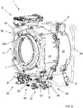
- the laundry washing machine 1 comprises an external casing or housing 2, in which a washing tub 3 is provided that contains a perforated washing drum 4 where the laundry to be treated can be loaded.
- the tub 3 and the drum 4 both preferably have a substantially cylindrical shape. Between the tub 3 and the drum 4 a gap 55 is defined.
- the housing 2 is provided with a loading/unloading door 8 which allows access to the drum 4.
- the tub 3 is preferably suspended in a floating manner inside the housing 2, advantageously by means of a number of coil springs and shock-absorbers 9.
- the drum 4 is advantageously rotated by an electric motor, not illustrated, which preferably transmits the rotating motion to the shaft of the drum 4, advantageously by means of a belt/pulley system.
- the motor can be directly associated with the shaft of the drum 4.
- the drum 4 is advantageously provided with holes which allow the liquid flowing therethrough. Said holes are typically and preferably homogeneously distributed on the cylindrical side wall of the drum 4.
- the tub 3 is preferably connected to the casing 2 by means of an elastic bellows 7, or gasket.
- the tub 3 preferably comprises two complementary hemi-shells 13 and 14 structured for being reciprocally coupled to form the tub 3.
- the bottom region 3a of the tub 3 preferably comprises a seat 15, or sump, suitable for receiving a heating device 10, as illustrated in Figure 5 .
- the heating device 10 when activated, heats the liquid inside the sump 15.
- the heating device 10 preferably comprises an electrical resistor of serpentine type.
- the heating device 10 is horizontally placed in the sump 15 and it extends substantially from a front part up to a rear part of the sump 15.
- the bottom region of the tub may be configured differently.
- the bottom region of the tub may not comprise a seat for the heating device.
- the heating device may be advantageously placed in the annular gap between the tub and the drum.
- the heating device may be different and suitable to heat the liquid in the tub, for example a hot air stream, a steam flow, microwaves source, infra-red rays, etc..
- a water supply circuit 5 is arranged in the upper part of the laundry washing machine 1 and is suited to supply water into the tub 3.
- the water supply circuit of a laundry washing machine is well known in the art, and therefore it will not be described in detail.
- the water supply circuit 5 advantageously comprises at least one supply valve 5a which is properly controlled, opened and closed, during the washing cycle.
- the laundry washing machine 1 advantageously comprises a detergent supplier 60 to supply detergent D into the tub 3.
- the laundry washing machine 1 advantageously further comprises a rinse additive supplier 70 to supply at least one rinse additive S into the tub 3.
- the detergent supplier 60 and the rinse additive supplier 70 are part of a removable drawer 6 provided with various compartments suited to be filled with detergent D and rinse additive S.
- the rinse additive S comprises a softener.
- the removable drawer may comprise further compartments suited to be filled with other type of rinse additives, such as fabric conditioners, waterproofing agents, fabric enhancers, rinse sanitization additives, chlorine-based additives, i.e. products which are suitable to be used in the rinsing phase of the washing program (as will be described in details along this description).
- rinse additives such as fabric conditioners, waterproofing agents, fabric enhancers, rinse sanitization additives, chlorine-based additives, i.e. products which are suitable to be used in the rinsing phase of the washing program (as will be described in details along this description).
- the water is supplied into the tub 3 from the water supply circuit 5 by making it flow through the drawer 6 and then through a supply pipe 18.
- the water which reaches the tub 3 can, in this case, selectively contain one of the products contained in the compartments of the drawer 6. Such water can be clean if the product in the drawer 6 has been already removed.
- a further separate water supply pipe can be provided, which supplies exclusively clean water into the tub 3, thus bypassing the compartments of the drawer 6.
- the water supply circuit 5 also preferably comprises a water flow sensor, for example a flow meter, which makes it possible to calculate the quantity of water supplied into the tub 3.
- a water flow sensor for example a flow meter
- the supply pipe 18, as schematically illustrated in figure 2 and visible in Figure 4 , is preferably arranged laterally with respect to the tub 3 and preferably terminates at an upper region 3b of the tub 3. More preferably, the supply pipe 18 terminates at a rear side of the washing tub 3.
- the water supply circuit 5 may then preferably comprise a water softening device for removal of calcium, magnesium and/or certain other metal cations in hard water before entering the tub.
- the water softening device advantageously comprises water softening agents for reducing the hardness degree of the water to be supplied to the washing tub.
- the water supply circuit 5 may comprise a regeneration-agent reservoir which is housed inside the casing and is structured for receiving salt or other regeneration agents for regenerating a water softening function of the water softening agents.
- Laundry washing machine 1 advantageously comprises a water outlet circuit 25 suitable for withdrawing liquid from the bottom region 3a of the tub 3.
- the water outlet circuit 25 preferably comprises a main pipe 17, a draining pump 26 and an outlet pipe 28 ending outside the housing 2.
- the water outlet circuit 25 preferably further comprise a filtering device 12 arranged between the main pipe 17 and the draining pump 26.
- the filtering device 12 is adapted to retain all the undesirable bodies (for example buttons that have come off the laundry, coins erroneously introduced into the laundry washing machine, etc.).
- This filtering device 12 can preferably be removed, and then cleaned, through a gate 14 placed advantageously on the front wall of the housing 2 of the laundry washing machine 1, as illustrated in Figure 1 .
- the main pipe 17 connects the bottom region 3a of the tub 3 to the filtering device 12.
- An inlet end 17a of the main pipe 17 is advantageously positioned at the lower point of the tub 3, more preferably at the lower point of the sump 15.
- An outlet end 17b of the main pipe 17 is connected to a front part 12a of the filtering device 12, as illustrated in Figure 6 .
- the filtering device 12 may be provided directly in the tub 3, preferably obtained in a single piece construction with the latter. In this case the filtering device 12 is fluidly connected to the outlet of the tub 3, in such a way that water and washing liquid drained from the tub 3 enters the filtering device 12.
- the draining pump 26 is preferably connected to a rear part 12b of the filtering device 12 and conveys the liquid to the outlet pipe 28 through an outlet 29, the latest better visible in Figure 5 where the outlet pipe 28 has been removed.
- Activation of the drain pump 26 drains the liquid, i.e. dirty water or water mixed with washing and/or rinsing products, from the tub 3 to the outside.
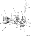
- Laundry washing machine 1 advantageously comprises a first recirculation circuit 30, or mixing circuit 30.
- the mixing circuit 30 is adapted to drain liquid from the bottom region 3a of the tub 3 and to re-admit such a liquid (recirculated mixing liquid) into a first region of the tub 3, which corresponds substantially to the same bottom region 3a of the tub 3.
- the mixing circuit 30 is adapted to drain liquid from the bottom of the sump 15 and to re-admit such a liquid (recirculated mixing liquid) again into the sump 15. More preferably, the liquid is re-admitted again into the sump 15 below the heating device 10.
- the mixing circuit 30 preferably comprises a first recirculation pump 31, a first pipe 32 connecting the filtering device 12 to the first recirculation pump 31 and a second recirculation pipe 33 advantageously provided with a terminal portion 34, or nozzle, better visible in Figure 5 .
- the terminal portion 34 advantageously ends inside the sump 15, as mentioned above.
- the liquid from the bottom region 3a of the tub 3 is conveyed again towards the bottom region 3a of the tub 3 by activation of the first recirculation pump 31.
- the liquid from the bottom region 3a of the tub 3 is conveyed towards the bottom region 3a of the tub 3 in the gap 55 between the tub 3 and the drum 4.
- the mixing circuit may comprise a dedicated pipe connecting the bottom region of the tub to the recirculation pump; in this case the mixing circuit is advantageously completely separated from the water outlet circuit, i.e. completely separated from the filtering device 12 and the main pipe 17.
- the mixing circuit (first recirculation circuit) is preferably realized for transferring a portion of a liquid from a bottom region of the tub to the same bottom region for mixing and/or dissolution of the products, as better described below.
- the mixing circuit (first recirculation circuit) is preferably realized for transferring liquid from a bottom region of the tub and for re-admitting such a liquid into the washing tub such that at least a portion of the re-admitted liquid reaches the bottom region of the washing tub without entering the washing drum. More preferably, the mixing circuit (first recirculation circuit) is preferably realized for transferring liquid from a bottom region of the tub and for re-admitting such a liquid into the washing tub such that all, or substantially all, the re-admitted liquid reaches the bottom region of the washing tub without entering the washing drum.
- Laundry washing machine 1 preferably comprises a second recirculation circuit 20 adapted to drain liquid from the bottom region 3a of the tub 3 and to re-admit such a liquid into a second region 3b, or upper region, of the tub 3.
- the second recirculation circuit 20 preferably comprises a second recirculation pump 21, a second pipe 22 connecting the filtering device 12 to the second recirculation pump 21 and a second recirculation pipe 23, preferably provided with a terminal nozzle 23a arranged preferably at the upper region 3b of the tub 3.
- the terminal nozzle 23a is opportunely arranged so that the liquid is sprayed directly into the drum 4. More preferably the terminal nozzle 23a is integrally formed in the bellows 7, as visible in Figure 3 , and the liquid is therefore advantageously sprayed in a direction the center of the perforated drum 4.
- the terminal nozzle 23a therefore, enhances distribution of liquid over the laundry through the perforated drum 4.
- the liquid from the bottom region 3a of the tub 3 is conveyed towards the upper region 3b of the tub 3 by activation of the second recirculation pump 21.
- the second recirculation circuit 20 is advantageously activated in order to improve wetting of the laundry inside the drum 4 and for reducing the water required in the whole washing program.
- the second recirculation circuit is properly realized for transferring a portion of a liquid from a bottom region of the tub, preferably from the sump, to an upper region of the tub in order to enhance absorption of the liquid by the laundry.
- laundry washing machine 1 comprises a device 19 suited to sense (or detect) the liquid level inside the tub 3.
- the sensor device 19 preferably comprises a pressure sensor which senses the pressure in the tub 3. From the values sensed by the sensor device 19 it is possible to determine the liquid level of the liquid inside the tub 3.
- laundry washing machine may preferably comprise (in addition to or as a replacement of the pressure sensor) a level sensor (for example mechanical, electro-mechanical, optical, etc.) adapted to sense (or detect) the liquid level inside the tub 3.
- Laundry washing machine 1 advantageously comprises a control unit, not illustrated, connected to the various parts of the laundry washing machine 1 in order to ensure its operation.
- the control unit is preferably connected to the water inlet circuit 5, the water outlet circuit 25, the recirculation circuits 30, 20, the heating device 10 and the electric motor and receives information from the various sensors provided on the laundry washing machine 1, like the pressure sensor 19, a temperature sensor, etc.
- Laundry washing machine 1 advantageously comprises an interface unit 12, connected to control unit, accessible to the user and by means of which the user may select and set the washing parameters, like for example a desired washing program.
- the washing parameters like for example a desired washing program.
- other parameters can optionally be inserted by the user, for example the washing temperature, the spinning speed, the load in terms of weight of the laundry to be washed, etc..
- control unit sets and controls the various parts of the laundry washing machine 1 in order to carry out the desired washing program.
- the laundry to be washed is first placed inside the drum 4 (step 100 of Figure 7 ).
- the user fills the compartments of the drawer 6 with the products needed for treatment of the laundry, i.e. detergent D and softener S.
- the user selects the desired washing program (step 110) depending, for example, on the type and on the dirty-level of the products to wash. Furthermore, as said before, in a preferred embodiment it is possible for the user to insert some parameters directly by the interface unit 12, for example the value of the washing temperature, the rotating speed of the drum 4 in the spinning phase, the duration of the washing program, etc.
- control unit sets the laundry washing machine 1 so that it starts the washing program.
- the selection of the desired washing program may be performed before placing the laundry into the drum 4 (step 100).
- a successive phase the laundry is subjected to a main washing cycle.
- the main washing cycle may be carried out according to any prior art technique and therefore it will not be described in detail.
- the laundry is washed with introduction of water and detergent D into the washing tub 3 and tumbled by rotation of the washing drum 4.
- the water and the detergent D are advantageously and preferably heated at a proper temperature by means of the heating device 10.
- the dirty washing liquid is advantageously drained to the outside by activating the drain pump 26 of the water outlet circuit 25 (step 125).
- the drum 4 is also typically rotated at a preferred rotational speed (for example about 150-250 rpm) in such a way that further dirty washing liquid (i.e. water mixed with detergent D) is extracted from the laundry.
- a preferred rotational speed for example about 150-250 rpm
- the extracted dirty washing liquid is advantageously drained to the outside by said drain pump 26 of the water outlet circuit 25 (step 125).
- the method comprises a rinsing phase, globally indicated with 130, which may comprise one or more rinsing cycles (steps 130a, 130b, ..., 130n).
- clean rinse water may be first added to the laundry, so as to be absorbed by the laundry.
- the clean water removes from the laundry the residual detergent D and/or dirty particles of the main washing cycle.
- the drum 4 is then rotated to extract water and dirty particles/detergent from the laundry: the dirty water extracted is drained from the tub 3 to the outside preferably by activating the drain pump 26 of the water outlet circuit 25.
- the laundry in a particular rinsing cycle (step 130a, 130b, ... , 130n), preferably in the last rinsing cycle (step 130n), the laundry is subjected to a treatment with a dose of a rinse additive.
- the laundry is subjected to a treatment with a dose of softener S.
- the laundry is preferably subjected to the treatment with the softener S in the last rinsing cycle (step 130n).
- the laundry may be treated with a different rinse additive, such as a fabric conditioner, a waterproofing agent, a fabric enhancer, a rinse sanitization additive, a chlorine-based additive, opportunely disposed inside a dedicated compartment of the drawer 6 at the beginning of the washing program.
- the laundry is preferably subjected to a sanitization treatment with this additive in the first rinsing cycle (step 130a).
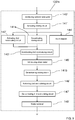
- the rinsing cycle (130n) according to the invention is better described with reference to Figure 8 .
- the last rinsing cycle (130n) we will refer to the last rinsing cycle (130n). It is clear that the invention may be referred to any of the rinsing cycle (step 130a, 130b, ..., 130n).
- a quantity Qs of softener S together with a first quantity Q1w of water W is introduced into the tub 3.
- the quantity Qs of softener S may be for example about 50 ml, if liquid softener is used, and the first quantity Q1w of water W may be for example about 5 or 6 litres.
- the introduction of the quantity Qs of softener S takes place preferably through the rinse additive supplier 70; the quantity Qs of softener S, be it powder or liquid, is preferably brought out of the apposite compartment of the drawer 6 by the first quantity Q1w of water W that passes through the proper compartment of the drawer 6.
- the first quantity Q1w of water W is conveyed to the proper compartment of the drawer 6 by activating (opening) the supply valve 5a of the water supply circuit 5.
- the supply valve 5a is activated for a predetermined water supplying time, for example 60-90 sec.
- the water supplying time obviously depends on the flow rate of the supply valve 5a.
- the quantity Qs of softener S and the first quantity Q1w of water W are introduced into the tub 3 through the supply pipe 18.
- the quantity Qs of softener S and the first quantity Q1w of water W may be advantageously introduced singularly into the tub 3 in different times.
- the quantity Qs of softener S and/or the first quantity Q1w of water W introduced into the tub 3 in said phase fall down on the bottom region 3a of the tub 3 by flowing inside the gap 55 between the tub 3 and the drum 4.
- a small quantity of softener S and/or a small quantity of water W introduced into the tub 3 and flowing inside the gap 55 may enter the drum 4, due to the position of the supply pipe 18.
- a relevant quantity of softener S and water W introduced into the tub 3 reach in any case the bottom region 3a of the tub 3, filling the sump 15.
- the mixing circuit 30 is activated (step 141).
- Activation of the mixing circuit 30 is advantageously carried out through activation of the first recirculation pump 31.
- activation of the mixing circuit 30 preferably stats at the same time of activation of the supply valve 5a.
- activation of the mixing circuit 30 more preferably starts after a delay time from activation of the supply valve 5a, for example after a delay time of 10 sec..
- the delay time ensures that the first recirculation pump 31 is working properly, i.e. guarantees that a quantity of liquid (softener S and/or water W) reaches the sump 15 when the first recirculation pump 31 is activated.
- the activation of the mixing circuit 30 may start even before activation of the supply valve 5a or, on the contrary, activation of the mixing circuit 30 may start after the supply valve 5a has been de-activated (closed). In the latter, the mixing circuit 30 is activated after all the quantity Qs of softener S and all the first quantity Q1w of water W have been introduced into the tub 3.
- the liquid (water W and softener S) is drained from the bottom region 3a of the tub 3 and re-admitted into to the same bottom region 3a of the tub 3.
- the liquid (water W and softener S) is drained from sump 15 and re-admitted again into the sump 15. More preferably, the liquid (water W and softener S) is drained from sump 15 and re-admitted again into the sump 15 below the heating device 10.
- Activation of the mixing circuit 30 advantageously mixes the softener S and the water W at the bottom region 3a of the tub 3, more preferably inside the sump 15.
- the mixing action causes the quantity Qs of softener S to be properly and homogeneously diluted in the first quantity Q1w of water W.
- the liquid mixture may be considered ready to be conveyed on the laundry inside the drum 4.
- the mixing circuit 30 is advantageously activated without any interruption, i.e. activated continuously for 60 sec. In different embodiments, nevertheless, the mixing circuit 30 may be activated intermittently. The mixing time is therefore obtained as the sum of the times in the successive activations.
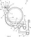
- the liquid mixture at the bottom region 3a of the tub 3 reaches a level Lm.
- the level Lm is in this case a level at which the liquid mixture partially touches the drum 4, i.e. a level Lm which is above the lower point of the drum 4.
- the level Lm depends on the quantity Qs of softener S and on the first quantity Q1w of water W previously introduced into the washing tub 3.
- the level Lm obviously depends also on the physical form of the tub 3 and/or of the drum 4.
- the liquid mixture touching the drum 4 may therefore partially enter the perforated drum 4 through the holes of the drum 4 and absorbed by the laundry.
- This liquid mixture absorbed by the laundry is advantageously a homogeneous liquid mixture obtained by the previous activation of the mixing circuit 30 (step 141).
- the laundry therefore absorbs the liquid mixture and the softener S binds to laundry. This improves the efficiency of the softener S on the laundry with respect to the known technique where the softener S not diluted reaches the load.
- the quantity Qs of softener S and the first quantity Q1w of water W may be adjusted to advantageously maintain the level L'm of the liquid mixture below the lower point of the drum 4, as illustrated in Figure 2 .
- activation of the mixing circuit 30 creates a homogeneous liquid mixture of softener S and water W at the bottom region 3a of the tub 3 and the liquid mixture does not enter, or substantially does not enter, the perforated drum 4.
- the liquid mixture obtained in the mixing step (step 141), which lies at the bottom region 3a of the tub 3 up to said particular level Lm, L'm, is then preferably conveyed on the laundry activating the second recirculation circuit 20 (step 142).
- Activation of the second recirculation circuit 20 is advantageously carried out through activation of the second recirculation pump 21 for a proper period of time.
- the mixing circuit 30 is preferably de-activated (step 141a).
- the liquid mixture from the bottom region 3a of the tub 3 is drained towards the upper region 3b of the tub 3 by means of the second recirculation pump 21.
- the second recirculation pump 21 takes the liquid mixture from the sump 15 and conveys it towards the upper region 3b of the tub 3 through the second recirculation pipe 23.
- the homogenous liquid mixture from the second recirculation pipe 23, and advantageously from its terminal nozzle 23a, is sprayed into the drum 4 over the laundry.
- the laundry absorbs the liquid mixture, the softener S binds to laundry and the level of the liquid mixture inside the tub 3 decreases.
- the softener S is distributed on the laundry items in a more homogenous form with respect to the known technique. This improves the efficiency of the softener S on the laundry.
- the second recirculation circuit 20 is preferably deactivated (step 143) when the liquid level inside the tub 3 reaches a level which is advantageously set at the bottom of the sump 15, i.e. when the liquid mixture is substantially totally drained and the tub 3 is substantially empty.
- the second recirculation circuit 20 is preferably deactivated after a preset period of time, for example 60 sec.
- the preset period of time may be an estimated period of time which is considered to be sufficient for draining all, or substantially all, the liquid mixture from the sump 15.
- the drum 4 is advantageously set rotated (step 144) so as to enhance the absorption of the liquid mixture by the laundry inside the drum 4.
- the drum 4 is advantageously set rotated both during and after the recirculation process (step 142).
- the drum 4 is advantageously set rotated (step 144) for a preset period of time, for example 4min, during which the softener S optimally binds to tumbled laundry.
- a second quantity Q2w of clean water W is preferably introduced into the tub 3 (step 145).
- the second quantity Q2w of clean water W may be, for example, about 7 litres.
- the introduction of the second quantity Q2w of clean water W takes place preferably through the water inlet circuit 5 with activation of the supply valve 5a.
- the supply valve 5a is activated for a predetermined water supplying time, for example 70-100 sec.
- the clean water W preferably passes through an empty compartment of the drawer 6.
- the second quantity Q2w of water W may be advantageously introduced directly into the tub 3 bypassing the drawer 6.
- the second recirculation circuit 20 is then activated (step 146) and the clean water W from the sump 15 is drained towards the upper region 3b of the tub 3 by means of the second recirculation pump 21.
- the clean water W is thus sprayed over the laundry through the terminal nozzle 23a.
- the drum 4 is preferably set rotated so as to enhance the absorption of clean water W.
- the water W is removed from the laundry (step 148).
- the removal of water W (step 148) preferably comprises a spinning phase during which the drum 4 is rotated at high speed (for example about 800-1500 rpm) to obtain the extraction of the water from the laundry.
- the drain pump 26 is activated to drain the liquid from the tub 3 to the outside through the outlet pipe 28.
- the rinsing cycle (step 130n) and the washing program after said removing step (step 148) may be considered terminated.
- the washing program may comprise one or more further spinning phases (as indicate with reference sign 150 in Figure 7 ) for the extraction of the residual water contained in the wet laundry.
- the phase of introducing a second quantity of clean water into the tub may be omitted.
- the steps (step 145, step 146 and step 147) of introducing and re-circulating the second quantity of clean water may be advantageously omitted.
- Figure 9 shows the flow chart of a further embodiment of the rinsing cycle (step 130'n) according to the invention.
- a quantity Qs of softener S together with a first quantity Q1w of water W is introduced into the tub 3.
- the quantity Qs of softener S may be for example about 50 ml, if liquid softener is used, and the first quantity Q1w of water W may be for example about 5 or 6 litres.
- the introduction of the quantity Qs of softener S takes place preferably through the rinse additive supplier 70; the quantity Qs of softener S, be it powder or liquid, is preferably brought out of the apposite compartment of the drawer 6 by the first quantity Q1w of water W that passes through the proper compartment of the drawer 6.
- the first quantity Q1w of water W is conveyed to the proper compartment of the drawer 6 by activating (opening) the supply valve 5a of the water supply circuit 5.
- the supply valve 5a is activated for a predetermined water supplying time, for example 60-100 sec.
- the water supplying time obviously depends on the flow rate of the supply valve 5a.
- the quantity Qs of softener S and the first quantity Q1w of water W are introduced into the tub 3 through the supply pipe 18.
- the quantity Qs of softener S and the first quantity Q1w of water W may be advantageously introduced singularly into the tub 3 in different times.
- the quantity Qs of softener S and/or the first quantity Q1w of water W introduced into the tub 3 in said phase fall down on the bottom region 3a of the tub 3 by flowing inside the gap 55 between the tub 3 and the drum 4.
- a small quantity of softener S and/or a small quantity of water W introduced into the tub 3 and flowing inside the gap 55 may enter the drum 4, due to the position of the supply pipe 18.
- a relevant quantity of softener S and water W introduced into the tub 3 reach in any case the bottom region 3a of the tub 3, filling the sump 15.
- the mixing circuit 30 is activated (step 141').
- Activation of the mixing circuit 30 is advantageously carried out through activation of the first recirculation pump 31.
- activation of the mixing circuit 30 preferably starts at the same time of activation of the supply valve 5a.
- activation of the mixing circuit 30 more preferably starts after a delay time from activation of the supply valve 5a, for example after a delay time of 10 sec..
- the delay time ensures that the first recirculation pump 31 is working properly, i.e. guarantees that a quantity of liquid (softener S and/or water W) reaches the sump 15 when the first recirculation pump 31 is activated.
- the activation of the mixing circuit 30 may start even before activation of the supply valve 5a or, on the contrary, activation of the mixing circuit 30 may start after the supply valve 5a has been de-activated (closed). In the latter, the mixing circuit 30 is activated after all the quantity Qs of softener S and all the first quantity Q1w of water W have been introduced into the tub 3.
- the liquid (water W and softener S) is drained from the bottom region 3a of the tub 3 and re-admitted into to the same bottom region 3a of the tub 3.
- the liquid (water W and softener S) is drained from sump 15 and re-admitted again into the sump 15. More preferably, the liquid (water W and softener S) is drained from sump 15 and re-admitted again into the sump 15 below the heating device 10.
- Activation of the mixing circuit 30 advantageously mixes the softener S and the water W at the bottom region 3a of the tub 3, more preferably inside the sump 15.
- the mixing action causes the quantity Qs of softener S to be properly and homogeneously diluted in the first quantity Q1w of water W.
- the liquid mixture may be considered ready to be conveyed on the laundry inside the drum 4.
- the mixing circuit 30 is advantageously activated without any interruption, i.e. activated continuously for 60 sec. In different embodiments, nevertheless, the mixing circuit 30 may be activated intermittently. The mixing time is therefore obtained as the sum of the times in the successive activations.
- the liquid mixture at the bottom region 3a of the tub 3 reaches a level Lm.
- the level Lm is in this case a level at which the liquid mixture partially touches the drum 4, i.e. a level Lm which is above the lower point of the drum 4.
- the level Lm depends on the quantity Qs of softener S and on the first quantity Q1w of water W previously introduced into the washing tub 3.
- the level Lm obviously depends also on the physical form of the tub 3 and/or of the drum 4.
- the liquid mixture touching the drum 4 may therefore partially enter the perforated drum 4 through the holes of the drum 4 and absorbed by the laundry.
- This liquid mixture absorbed by the laundry is advantageously a homogeneous liquid mixture obtained by the previous activation of the mixing circuit 30 (step 141').
- the laundry therefore absorbs the liquid mixture and the softener S binds to laundry. This improves the efficiency of the softener S on the laundry with respect to the known technique where the softener S not diluted reaches the load.
- the quantity Qs of softener S and the first quantity Q1w of water W may be adjusted to advantageously maintain the level L'm of the liquid mixture below the lower point of the drum 4, as illustrated in Figure 2 .
- activation of the mixing circuit 30 creates a homogeneous liquid mixture of softener S and water W at the bottom region 3a of the tub 3 and the liquid mixture does not enter, or substantially does not enter, the perforated drum 4.
- the liquid mixture obtained in the mixing step (step 141'), which lies at the bottom region 3a of the tub 3 up to said particular level Lm, L'm, is then is then preferably partially conveyed on the laundry activating the second recirculation circuit 20 (step 142').
- Activation of the second recirculation circuit 20 is advantageously carried out through activation of the second recirculation pump 21 for a proper period of time.
- the mixing circuit 30 may be de-activated (step 141'a). In the preferred embodiment here described, nevertheless, the mixing circuit 30 is kept working. De-activation of the mixing circuit 30 (step 141'b) is preferably carried out successively during the washing program, as described below.
- the liquid mixture from the bottom region 3a of the tub 3 is drained towards the upper region 3b of the tub 3 by means of the second recirculation pump 21.
- the second recirculation pump 21 takes the liquid mixture from the sump 15 and conveys it towards the upper region 3b of the tub 3 through the second recirculation pipe 23.
- the homogenous liquid mixture from the second recirculation pipe 23, and advantageously from its terminal nozzle 23a, is sprayed into the perforated drum 4 and over the laundry.
- the laundry absorbs the liquid mixture, the softener S binds to laundry and the liquid mixture inside the tub 3 decreases to a new level Ls.
- the softener S is distributed on the laundry items in a more homogenous form with respect to the known technique. This improves the efficiency of the softener S on the laundry.
- the second recirculation circuit 20 is preferably deactivated (step 143') when the liquid level inside the tub 3 reaches the new level Ls.
- the new level Ls is preferably substantially at the lower point of the drum 4, as illustrated in Figure 2 .
- the second recirculation circuit 20 is preferably deactivated after a preset period of time, for example 30 sec.
- the preset period of time may be an estimated period of time which is considered to be sufficient the liquid mixture reaches the new level Ls.
- the new level Ls may be different, below or above the lower point of the drum 4.
- the drum 4 is advantageously set rotated (step 144') so as to enhance the absorption of the liquid mixture by the laundry inside the drum 4.
- the drum 4 is advantageously set rotated both during and after the recirculation process (step 142').
- the drum 4 is advantageously set rotated (step 144') for a preset period of time, for example 4min, during which the softener S optimally binds to tumbled laundry.
- step 144' a further quantity of liquid mixture directly enters the perforated drum 4 through the holes of the drum 4 and then absorbed by the laundry.
- This liquid mixture absorbed by the laundry is advantageously a homogeneous mixture. This improves the efficiency of the softener S on the laundry with respect to the known technique where the softener S not diluted reaches the load.
- a second quantity Q2w of clean water W is preferably introduced into the tub 3 (step 145').
- the second quantity Q2w of clean water W may be, for example, about 7 litres.
- the introduction of the second quantity Q2w of clean water W takes place preferably through the water inlet circuit 5 with activation of the supply valve 5a.
- the clean water W preferably passes through an empty compartment of the drawer 6.
- the second quantity Q2w of water W may be advantageously introduced directly into the tub 3 bypassing the drawer 6.
- the second quantity Q2w of water W reaches the bottom region 3a of the tub 3 and is here added to the liquid mixture.
- the mixing circuit 30 is still activated (step 141') and the liquid mixture is further mixed with the second quantity Q2w of water W.
- the mixing action causes the liquid mixture to be further diluted with the second quantity Q2w of water W.
- the method preferably provide for the activation of the mixing circuit 30 for mixing the liquid mixture with the second quantity Q2w of water W introduced in the tub 3.
- the mixing circuit 30 is preferably de-activated (step 141b).
- the second recirculation circuit 20 is then activated (step 146') and the diluted liquid from the sump 15 is drained towards the upper region 3b of the tub 3 by means of the second recirculation pump 21.
- the diluted liquid is thus sprayed over the laundry through the terminal nozzle 23a.
- the drum 4 is preferably set rotated so as to enhance the absorption of clean water W.
- the water W is removed from the laundry (step 148').
- the removal of water W (step 148') preferably comprises a spinning phase during which the drum 4 is rotated at high speed (for example about 800-1500 rpm) to obtain the extraction of the water from the laundry.
- the drain pump 26 is activated to drain the liquid from the tub 3 to the outside through the outlet pipe 28.
- the rinsing cycle (step 130n') and the washing program after said removing step (step 148') may be considered terminated.
- the washing program may comprise one or more further spinning phases (as indicate with reference sign 150 in Figure 7 ) for the extraction of the residual water contained in the wet laundry.
- Figure 10 shows a schematic view of a further embodiment of a laundry washing machine 201 wherein a method according to the present invention may be performed.
- the laundry washing machine 201 differs from the laundry washing machine 1 previously described in particular with reference to Figure 2 in that the second recirculation circuit 20 is omitted.
- Phases and/or steps with the same reference numbers of the first embodiment correspond to phases and/or steps described above for the first embodiment.
- the laundry to be washed is first placed inside the drum 4 (step 100 of Figure 11 ).
- the user fills the compartments of the drawer 6 with the products needed for treatment of the laundry, i.e. detergent D and softener S.
- the user selects the desired washing program (step 110).
- control unit sets the laundry washing machine 1 so that it starts the washing program.
- step 120 the laundry is subjected to a main washing cycle.
- the dirty washing liquid is advantageously drained to the outside by activating the drain pump 26 of the water outlet circuit 25 (step 125).
- the drum 4 is also typically rotated at a preferred rotational speed (for example about 150-250 rpm) in such a way that further dirty washing liquid (i.e. water mixed with detergent D) is extracted from the laundry.
- a preferred rotational speed for example about 150-250 rpm
- the extracted dirty washing liquid is advantageously drained to the outside by said drain pump 26 of the water outlet circuit 25 (step 125).
- the method comprises a rinsing phase, globally indicated with 230, which may comprise one or more rinsing cycles (steps 230a, 230b, ..., 230n).
- clean rinse water may be first added to the laundry, so as to be absorbed by the laundry.
- the clean water removes from the laundry the residual detergent D and/or dirty particles of the main washing cycle.
- the drum 4 is then rotated to extract water and dirty particles/detergent from the laundry: the dirty water extracted is drained from the tub 3 to the outside preferably by activating the drain pump 26 of the water outlet circuit 25.
- the laundry in a particular rinsing cycle (step 230a, 230b, ... , 230n), preferably in the last rinsing cycle (step 230n), the laundry is subjected to a treatment with a dose of a rinse additive.
- the laundry is subjected to a treatment with a dose of softener S.
- the laundry is preferably subjected to the treatment with the softener S in the last rinsing cycle (step 230n).
- the laundry may be treated with a different rinse additive, such as a fabric conditioner, a waterproofing agent, a fabric enhancer, a rinse sanitization additive, a chlorine-based additive, opportunely disposed inside a dedicated compartment of the drawer 6 at the beginning of the washing program.
- the laundry is preferably subjected to a sanitization treatment with this additive in the first rinsing cycle (step 230a).
- the rinsing cycle (230n) according to the invention is better described with reference to Figure 12 .
- hereinafter we will refer to the last rinsing cycle (230n). It is clear that the invention may be referred to any of the rinsing cycle (step 230a, 230b, ..., 230n).
- a quantity Qs of softener S together with a first quantity Q1w of water W is introduced into the tub 3.
- the quantity Qs of softener S may be for example about 50 ml, if liquid softener is used, and the first quantity Q1w of water W may be for example about 5 or 6 litres.
- the introduction of the quantity Qs of softener S takes place preferably through the rinse additive supplier 70; the quantity Qs of softener S, be it powder or liquid, is preferably brought out of the apposite compartment of the drawer 6 by the first quantity Q1w of water W that passes through the proper compartment of the drawer 6.
- the quantity Qs of softener S and the first quantity Q1w of water W are introduced into the tub 3 through the supply pipe 18.
- the quantity Qs of softener S and the first quantity Q1w of water W may be advantageously introduced singularly into the tub 3 in different times.
- the quantity Qs of softener S and/or the first quantity Q1w of water W introduced into the tub 3 in said phase fall down on the bottom region 3a of the tub 3 by flowing inside the gap 55 between the tub 3 and the drum 4.
- a small quantity of softener S and/or a small quantity of water W introduced into the tub 3 and flowing inside the gap 55 may enter the drum 4, due to the position of the supply pipe 18.
- a relevant quantity of softener S and water W introduced into the tub 3 reach in any case the bottom region 3a of the tub 3, filling the sump 15.
- the mixing circuit 30 is activated (step 241).
- Activation of the mixing circuit 30 is advantageously carried out through activation of the first recirculation pump 31.
- activation of the mixing circuit 30 preferably starts at the same time of activation of the supply valve 5a.
- activation of the mixing circuit 30 more preferably starts after a delay time from activation of the supply valve 5a, for example after a delay time of 10 sec..
- the delay time ensures that the first recirculation pump 31 is working properly, i.e. guarantees that a quantity of liquid (softener S and/or water W) reaches the sump 15 when the first recirculation pump 31 is activated.
- the activation of the mixing circuit 30 may start even before activation of the supply valve 5a or, on the contrary, activation of the mixing circuit 30 may start after the supply valve 5a has been de-activated (closed). In the latter, the mixing circuit 30 is activated after all the quantity Qs of softener S and all the first quantity Q1w of water W have been introduced into the tub 3.
- the liquid (water W and softener S) is drained from the bottom region 3a of the tub 3 and re-admitted into to the same bottom region 3a of the tub 3.
- the liquid (water W and softener S) is drained from sump 15 and re-admitted again into the sump 15. More preferably, the liquid (water W and softener S) is drained from sump 15 and re-admitted again into the sump 15 below the heating device 10.
- Activation of the mixing circuit 30 advantageously mixes the softener S and the water W at the bottom region 3a of the tub 3, more preferably inside the sump 15.
- the mixing action causes the quantity Qs of softener S to be properly and homogeneously diluted in the first quantity Q1w of water W.
- a homogeneous liquid mixture of softener S and water W is prepared at the bottom region 3a of the tub 3.
- the liquid mixture may be considered ready to be conveyed on the laundry inside the drum 4.
- the mixing circuit 30 is advantageously activated without any interruption, i.e. activated continuously for 60-80 sec. In different embodiments, nevertheless, the mixing circuit 30 may be activated intermittently. The mixing time is therefore obtained as the sum of the times in the successive activations.
- the liquid mixture at the bottom region 3a of the tub 3 reaches a level Lm.
- the level Lm is in this case a level at which the liquid mixture partially touches the drum 4, i.e. a level Lm which is above the lower point of the drum 4.
- the level Lm depends on the quantity Qs of softener S and on the first quantity Q1w of water W previously introduced into the washing tub 3.
- the level Lm obviously depends also on the physical form of the tub 3 and/or of the drum 4.
- the liquid mixture touching the drum 4 may therefore partially enter the perforated drum 4 through the holes of the drum 4 and absorbed by the laundry.
- This liquid mixture absorbed by the laundry is advantageously a homogeneous liquid mixture obtained by the previous activation of the mixing circuit 30 (step 241).
- the laundry therefore absorbs the liquid mixture and the softener S binds to laundry. This improves the efficiency of the softener S on the laundry with respect to the known technique where the softener S not diluted reaches the load.
- the quantity Qs of softener S and the first quantity Q1w of water W may be adjusted to advantageously maintain the level L'm of the liquid mixture below the lower point of the drum 4, as illustrated in Figure 10 .
- activation of the mixing circuit 30 creates a homogeneous liquid mixture of softener S and water W at the bottom region 3a of the tub 3 and the liquid mixture does not enter, or substantially does not enter, the perforated drum 4 (in particular when the drum 4 is not set rotated).
- the liquid mixture obtained in the mixing step (step 241), which lies at the bottom region 3a of the tub 3 up to said particular level Lm, L'm, is then conveyed on the laundry exclusively through the holes of the drum 4.
- the same drum 4 is set rotated (step 244).
- the drum 4 is advantageously set rotated (step 244) for a preset period of time, for example 4min, during which the softener S optimally binds to tumbled laundry.
- the liquid mixture at level Lm directly enters the perforated drum 4 through the holes of the drum 4 and then absorbed by the laundry.
- This liquid mixture absorbed by the laundry is advantageously a homogeneous mixture. This improves the efficiency of the softener S on the laundry with respect to the known technique.
- the drum 4 creates turbulence in the liquid mixture. Turbulence further enhances the liquid mixture flowing through the holes of the same drum 4. In this particular case, i.e. when the drum is set rotated (step 244) and thanks to turbulence, the liquid mixture may flow through the holes of the drum 4 even if its level L'm is below the lower point of the drum 4.
- step 244 During rotation of the drum 4 (step 244) most of the liquid mixture is conveyed inside the drum 4 through the holes of the drum 4, and there absorbed by the laundry.
- the preset period of time may be an estimated period of time which is considered to be sufficient for conveying all, or substantially all, the liquid mixture inside the drum 4.
- the mixing circuit 30 may be preferably de-activated (step 241a). In the preferred embodiment here described, nevertheless, the mixing circuit 30 is kept working. De-activation of the mixing circuit 30 (step 241b) is carried out successively during the washing program, as described below.
- a second quantity Q2w of clean water W is preferably introduced into the tub 3.
- the second quantity Q2w of clean water W may be, for example, about 7 litres.
- the introduction of the second quantity Q2w of clean water W takes place preferably through the water inlet circuit 5 with activation of the supply valve 5a.
- the supply valve 5a is activated for a predetermined water supplying time, for example 70-120 sec.
- the clean water W preferably passes through an empty compartment of the drawer 6.
- the second quantity Q2w of water W may be advantageously introduced directly into the tub 3 bypassing the drawer 6.
- the quantity Q2w of clean water W introduced inside the tub 3 increases the liquid mixture level inside the washing tub 3 up to a new higher level, for example the level Ln illustrated in Figure 10 .
- the mixing circuit 30 is still activated (step 241) and the liquid mixture is further mixed with the second quantity Q2w of water W.
- the mixing action causes the liquid mixture to be further diluted with the second quantity Q2w of water W.
- the method preferably provide for the activation of the mixing circuit 30 for mixing the liquid mixture with the second quantity Q2w of water W introduced in the tub 3.
- the mixing circuit 30 is then preferably de-activated (step 241b).
- the diluted liquid mixture at level Ln is conveyed on the laundry exclusively through the holes of the drum 4.
- the same drum 4 is set rotated (step 246).
- the drum 4 is advantageously set rotated (step 246) for a preset period of time, for example 8min.
- the diluted liquid mixture directly enters the perforated drum 4 through the holes of the drum 4.
- the drum 4 creates turbulence in the diluted liquid mixture. Turbulence further enhances the diluted liquid mixture flowing through the holes of the same drum 4.
- the water W is removed from the laundry (step 248).
- the removal of water W preferably comprises a spinning phase during which the drum 4 is rotated at high speed (for example about 800-1500 rpm) to obtain the extraction of the water from the laundry.
- the drain pump 26 is activated to drain the liquid from the tub 3 to the outside through the outlet pipe 28.
- the rinsing cycle (step 230n) and the washing program after said removing step (step 248) may be considered terminated.
- the washing program may comprise one or more spinning phases (as indicate with reference sign 150 in Figure 11 ) for the extraction of the residual water contained in the wet laundry.
- the phase of introducing a second quantity of clean water into the tub may be omitted.
- the steps (step 245 and step 246) of introducing the second quantity of clean water inside the tub and conveying it inside the drum through its holes may be advantageously omitted.
- this preferred embodiment of the method is advantageously carried out in laundry machine 201 of Figure 10 , as said above.
- This method in fact, may be advantageously carried out in a laundry washing machine not provided with a second recirculation circuit. Nevertheless, this method may be also carried out in laundry machine 1 previously described in which the second recirculation circuit 20 is not used during the rinsing cycle.
- Figure 13 shows a schematic view of a further embodiment of a laundry washing machine 301 wherein a method according to the present invention may be performed.
- the laundry washing machine 301 differs from the laundry washing machine 1 described with reference to Figures from 1 to 6 only in that the supply pipe 318 does not terminates at the upper region 3b of the tub 3 but at the bottom region 3a of the tub 3.
- washing method according to the present invention performed in laundry washing machine 301 may be the same described above with reference to laundry washing machine 1 of Figures from 1 to 6.
- the arrangement of the supply pipe 318 at the bottom region 3a of the tub 3 better guarantees that all, or substantially all, the quantity of liquid coming from the drawer (water W and/or softener S) introduced into the tub 3 falls down on the bottom region 3a of the tub 3 substantially without absorption from the laundry.
- the concentrated softener S introduced into the tub 3 does not enter the perforated drum 4 through its holes and falls down on the bottom region 3a of the tub 3 without absorption from the laundry.
- Figure 14 shows another schematic view of a further embodiment of a laundry washing machine 401 wherein a method according to the present invention may be performed.
- the laundry washing machine 401 differs from the laundry washing machine 201 described with reference to Figure 10 only in that the supply pipe 318 does not terminates at the upper region 3b of the tub 3 but at the bottom region 3a of the tub 3.
- the arrangement of the supply pipe 318 at a bottom region 3a of the tub 3 better guarantees that all, or substantially all, the quantity of liquid coming from the drawer (water W and/or softener S) introduced into the tub 3 falls down on the bottom region 3a of the tub 3 substantially without absorption from the laundry.
- the method of the invention may be advantageously carried out in a different laundry washing machine wherein the rinse additive supplier comprises a storage tank which automatically dose the rinse additive, in particular the softener, according to the cycle of the washing.
- the tank is advantageously filled only once with softener for a plurality of washing programs.
- the rinse additive from the storage tank is directly conveyed to the tub or conveyed to the drawer by means of a controlled dosing pump.
- the present invention allows all the set objects to be achieved.
- it makes it possible to obtain a method for treating laundry with improved softener dissolution with respect to the method of the prior art.
- laundry washing machines illustrated in the enclosed figures, and with reference to which some embodiments of the method according to the invention have been described, are of the front-loading type; however it is clear that the method according to the invention can be applied as well to a top-loading washing machine, substantially without any modification.
Claims (15)
- Verfahren zum Behandeln von Wäsche in einer Maschine (1; 201; 301; 401) zum Waschen von Wäsche des Typs, der Folgendes umfasst:- eine drehbare, perforierte Waschtrommel (4), die mit Löchern versehen ist und ausgelegt ist, Wäsche aufzunehmen;- einen Waschbottich (3) außerhalb der Waschtrommel (4);- einen Wasserzufuhrkreislauf (5), der wenigstens ein Zufuhrventil (5a) zum Zuführen von Wasser (W) in den Waschbottich (3) umfasst;- eine Reinigungsmittelzufuhrvorrichtung (60) zum Zuführen von Reinigungsmittel (D) in den Waschbottich (3);- eine Zufuhrvorrichtung (70) für einen Spül-Zusatzstoff zum Zuführen wenigstens eines Spül-Zusatzstoffes (S) in den Waschbottich (3);- einen ersten Umwälzkreislauf (30), der zum Entnehmen von Flüssigkeit von einem Bodenbereich (3a) des Waschbottichs (3) und zum erneuten Hinzugeben dieser Flüssigkeit in den Waschbottich (3) geeignet ist, so dass wenigstens ein Teil der erneut hinzugegebenen Flüssigkeit den Bodenbereich (3a) des Waschbottichs (3) erreicht, ohne in die Waschtrommel (4) einzudringen;wobei das Verfahren wenigstens eine Waschphase (120), während der die Wäsche durch das Einleiten von Wasser und Reinigungsmittel (D) in den Waschbottich (3) gewaschen und durch Drehen der Waschtrommel (4) zum Taumeln gebracht wird, wenigstens eine nachfolgende Ablaufphase (125) zum Ablaufen lassen von Flüssigkeit aus dem Waschbottich (3) und nach der Ablaufphase (125) wenigstens einen Spülzyklus (130a, 130b, ..., 130n; 130'n; 230a, 230b, ..., 230n), währenddessen die Wäsche mittels des wenigstens einen Spül-Zusatzstoffes (S) behandelt wird, umfasst;
dadurch gekennzeichnet, dass der Spülzyklus (130n; 130'n; 230n) die folgenden Schritte umfasst:- Einleiten (140; 140'; 240) einer Menge (Qs) des Spül-Zusatzstoffes (S) in den Waschbottich (3);- Einleiten (140; 140'; 240) einer ersten Menge (Q1w) von Wasser (W) in den Waschbottich (3) durch Aktivieren des Zufuhrventils (5a);- Aktivieren (141; 141'; 241) des ersten Umwälzkreislaufes (30) zum Entnehmen von Flüssigkeit aus dem Waschbottich (3) und zum erneuten Hinzugeben dieser Flüssigkeit in den Waschbottich (3), so dass ein verdünnter Spül-Zusatzstoff durch Mischen der Menge (Qs) des Spül-Zusatzstoffes (S) mit der ersten Menge (Q1w) von Wasser (W) bei dem Bodenbereich (3a) des Waschbottichs (3) erhalten wird;- Einleiten (142; 142') des verdünnten Spül-Zusatzstoffes in die Waschtrommel (4), damit er durch die Wäsche aufgenommen wird. - Verfahren nach Anspruch 1, dadurch gekennzeichnet, dass der Schritt der Aktivierung (141; 141'; 241) des ersten Umwälzkreislaufs (30) zum gleichen Zeitpunkt wie die Aktivierung des Zufuhrventils (5a) beginnt.
- Verfahren nach einem der vorhergehenden Ansprüche, dadurch gekennzeichnet, dass der Schritt (142; 142') des Einleitens des verdünnten Spül-Zusatzstoffes in die Waschtrommel (4) mittels eines zweiten Umwälzkreislaufs (30) ausgeführt wird, der geeignet ist, Flüssigkeit von dem Bodenbereich (3a) des Waschbottichs (3) zu entnehmen und diese Flüssigkeit in einen oberen Bereich (3b) des Waschbottichs (3) erneut hinzuzugeben.
- Verfahren nach einem der vorhergehenden Ansprüche, dadurch gekennzeichnet, dass der Schritt (142; 142') des Einleitens des verdünnten Spül-Zusatzstoffes in die Waschtrommel (4) durch Transportieren des verdünnten Spül-Zusatzstoffs von dem Bodenbereich (3a) des Waschbottichs (3) direkt durch die Löcher der Waschtrommel (4), wenn der verdünnte Spül-Zusatzstoff auf einem Pegel (Lm) in dem Waschbottich (3) ist, bei dem der verdünnte Spül-Zusatzstoff die Waschtrommel (4) berührt, bzw. wenn die Waschtrommel (4) in Drehung versetzt wird, ausgeführt wird.
- Verfahren nach einem der vorhergehenden Ansprüche, dadurch gekennzeichnet, dass während des bzw. nach dem Schritt des Einleitens (142; 142') des verdünnten Spül-Zusatzstoffes in die Waschtrommel (4) die Waschtrommel (4) in Drehung versetzt wird.
- Verfahren nach einem der vorhergehenden Ansprüche, dadurch gekennzeichnet, dass der Schritt des Einleitens (140; 140'; 240) einer Menge (Qs) des Spül-Zusatzstoffes (S) in den Waschbottich (3) so ausgeführt wird, dass wenigstens ein Teil des Spül-Zusatzstoffes (S) den Bodenbereich (3a) des Waschbottichs (3) erreicht, ohne in die Waschtrommel (4) einzudringen.
- Verfahren nach einem der vorhergehenden Ansprüche, dadurch gekennzeichnet, dass nach dem Schritt des Einleitens (142; 242') des verdünnten Spül-Zusatzstoffes in die Waschtrommel (4) das Verfahren ferner einen Schritt des Einleitens einer zweiten Menge (Q2w) von Wasser (W) in den Waschbottich (3) umfasst.
- Verfahren nach Anspruch 7, dadurch gekennzeichnet, dass es einen weiteren Schritt (145; 145'; 245) des Einleitens einer Flüssigkeit von dem Bodenbereich (3a) des Waschbottichs (3) in die Waschtrommel (4) umfasst, damit diese von der Wäsche aufgenommen wird.
- Verfahren nach Anspruch 8, dadurch gekennzeichnet, dass der weitere Schritt des Einleitens von Flüssigkeit in die Waschtrommel (4) mittels eines zweiten Umwälzkreislaufs (20) ausgeführt wird, der zum Entnehmen von Flüssigkeit von dem Bodenbereich (3a) des Waschbottichs (3) und zum erneuten Hinzugeben dieser Flüssigkeit in einen oberen Bereich (3b) des Waschbottichs (3) geeignet ist.
- Verfahren nach Anspruch 8 oder 9, dadurch gekennzeichnet, dass der weitere Schritt des Einleitens von Flüssigkeit in die Waschtrommel (4) durch Transportieren der Flüssigkeit von dem Bodenbereich (3a) des Waschbottichs (3) direkt durch die Löcher der Waschtrommel (4), wenn die Flüssigkeit auf einem Pegel (Ln) in dem Waschbottich (3) ist, bei dem die Flüssigkeit die Waschtrommel (4) berührt, bzw. wenn die Waschtrommel (4) in Drehung versetzt wird, ausgeführt wird.
- Verfahren nach einem der Ansprüche 8 bis 10, dadurch gekennzeichnet, dass während des bzw. nach dem weiteren Schritt des Einleitens von Flüssigkeit in die Waschtrommel (4) die Waschtrommel (4) in Drehung versetzt wird.
- Verfahren nach einem der vorhergehenden Ansprüche, dadurch gekennzeichnet, dass der Spülzyklus (130n; 130'n; 230n) ferner einen Schritt (148; 148'; 248) zum Entfernen von Wasser von der Wäsche nach außen umfasst.
- Verfahren nach einem der vorhergehenden Ansprüche, dadurch gekennzeichnet, dass es eine oder mehrere abschließende Schleuderphasen (150) zum Abziehen von restlichem Wasser, das in der Wäsche enthalten ist, umfasst.
- Verfahren nach einem der vorhergehenden Ansprüche, dadurch gekennzeichnet, dass der erste Umwälzkreislauf (30) geeignet ist, Flüssigkeit aus einer Wanne (15) bei dem Bodenbereich (3a) des Waschbottichs (3) zu entnehmen und diese Flüssigkeit erneut in die Wanne (15) hinzuzugeben.
- Maschine (1; 201; 301; 401) zum Waschen von Wäsche des Typs, der Folgendes umfasst:- eine drehbare, perforierte Waschtrommel (4), die mit Löchern versehen ist und ausgelegt ist, Wäsche aufzunehmen;- einen Waschbottich (3) außerhalb der Waschtrommel (4);- einen Wasserzufuhrkreislauf (5), der wenigstens ein Zufuhrventil (5a) zum Zuführen von Wasser (W) in den Waschbottich (3) umfasst;- eine Reinigungsmittel-Zufuhrvorrichtung (60) zum Zuführen von Reinigungsmittel (D) in den Waschbottich (3);- eine Zufuhrvorrichtung (70) für einen Spül-Zusatzstoff zum Zuführen wenigstens eines Spül-Zusatzstoffes (S) in den Waschbottich (3);- einen ersten Umwälzkreislauf (30), der geeignet ist, Flüssigkeit von einem Bodenbereich (3a) des Waschbottichs (3) zu entnehmen und diese Flüssigkeit erneut in den Waschbottich (3) hinzuzugeben, so dass wenigstens ein Teil der erneut hinzugegebenen Flüssigkeit den Bodenbereich (3a) des Waschbottichs (3) erreicht, ohne in die Waschtrommel (4) einzudringen;- eine Steuereinheit, die mit den verschiedenen Bauteilen der Maschine zum Waschen von Wäsche (1; 201; 301; 401) verbunden ist, um deren Betrieb sicherzustellen;wobei die Steuereinheit konfiguriert ist, ein Verfahren nach einem der vorhergehenden Ansprüche zu realisieren.
Applications Claiming Priority (1)
| Application Number | Priority Date | Filing Date | Title |
|---|---|---|---|
| PCT/EP2013/066785 WO2015022002A1 (en) | 2013-08-12 | 2013-08-12 | Method for treating laundry in a laundry washing machine and laundry washing machine |
Publications (2)
| Publication Number | Publication Date |
|---|---|
| EP3033450A1 EP3033450A1 (de) | 2016-06-22 |
| EP3033450B1 true EP3033450B1 (de) | 2017-06-28 |
Family
ID=48986109
Family Applications (1)
| Application Number | Title | Priority Date | Filing Date |
|---|---|---|---|
| EP13750020.3A Active EP3033450B1 (de) | 2013-08-12 | 2013-08-12 | Verfahren zum waschen von wäsche in einer wäschewaschmaschine sowie wäschewaschmaschine |
Country Status (4)
| Country | Link |
|---|---|
| US (1) | US9777423B2 (de) |
| EP (1) | EP3033450B1 (de) |
| AU (1) | AU2013398102B2 (de) |
| WO (1) | WO2015022002A1 (de) |
Families Citing this family (11)
| Publication number | Priority date | Publication date | Assignee | Title |
|---|---|---|---|---|
| EP2977503B1 (de) * | 2014-07-25 | 2019-04-24 | Electrolux Appliances Aktiebolag | Wäschetrocknervorrichtung mit Heizeinheit mit einstellbaren Temperaturschwellwerten |
| WO2016155813A1 (en) * | 2015-04-01 | 2016-10-06 | Electrolux Appliances Aktiebolag | Method for treating laundry in a laundry washing machine and laundry washing machine |
| KR102578676B1 (ko) * | 2016-10-05 | 2023-09-13 | 엘지전자 주식회사 | 세탁기의 제어방법 |
| KR102578677B1 (ko) * | 2016-10-05 | 2023-09-13 | 엘지전자 주식회사 | 세탁기의 제어방법 |
| USD825123S1 (en) * | 2017-05-31 | 2018-08-07 | Whirlpool Corporation | Fabric care appliance |
| USD826490S1 (en) * | 2017-05-31 | 2018-08-21 | Whirlpool Corporation | Fabric care appliance |
| USD878687S1 (en) | 2017-05-31 | 2020-03-17 | Whirlpool Corporation | Fabric care appliance |
| USD878688S1 (en) * | 2017-05-31 | 2020-03-17 | Whirlpool Corporation | Fabric care appliance |
| USD858915S1 (en) | 2017-05-31 | 2019-09-03 | Whirlpool Corporation | Fabric care appliance |
| USD825122S1 (en) * | 2017-05-31 | 2018-08-07 | Whirlpool Corporation | Fabric care appliance |
| KR20230151374A (ko) * | 2022-04-25 | 2023-11-01 | 삼성전자주식회사 | 세탁기 및 세탁기의 제어방법 |
Family Cites Families (6)
| Publication number | Priority date | Publication date | Assignee | Title |
|---|---|---|---|---|
| US5233718A (en) * | 1992-01-02 | 1993-08-10 | Whirlpool Corporation | Tumble method of rinsing fabric in a horizontal axis washer |
| US5249441A (en) * | 1992-01-02 | 1993-10-05 | Whirlpool Corporation | Slit valve for automatic washer |
| US5271251A (en) * | 1992-01-02 | 1993-12-21 | Whirlpool Corporation | Vertical axis washer |
| US5199127A (en) * | 1992-01-02 | 1993-04-06 | Whirlpool Corporation | Method for rinsing fabric articles in a vertical axis washer |
| IT1275186B (it) * | 1995-02-10 | 1997-07-30 | Candy Spa | Procedimento di lavaggio per macchina lavabiancheria |
| EP2540896B1 (de) * | 2011-06-30 | 2016-04-13 | Electrolux Home Products Corporation N.V. | Verfahren zum Waschen von Wäsche in einer Waschmaschine |
-
2013
- 2013-08-12 US US14/911,905 patent/US9777423B2/en active Active
- 2013-08-12 AU AU2013398102A patent/AU2013398102B2/en active Active
- 2013-08-12 WO PCT/EP2013/066785 patent/WO2015022002A1/en active Application Filing
- 2013-08-12 EP EP13750020.3A patent/EP3033450B1/de active Active
Non-Patent Citations (1)
| Title |
|---|
| None * |
Also Published As
| Publication number | Publication date |
|---|---|
| US20160194807A1 (en) | 2016-07-07 |
| AU2013398102B2 (en) | 2019-06-27 |
| US9777423B2 (en) | 2017-10-03 |
| WO2015022002A1 (en) | 2015-02-19 |
| AU2013398102A1 (en) | 2016-02-18 |
| EP3033450A1 (de) | 2016-06-22 |
Similar Documents
| Publication | Publication Date | Title |
|---|---|---|
| EP3033450B1 (de) | Verfahren zum waschen von wäsche in einer wäschewaschmaschine sowie wäschewaschmaschine | |
| US10648113B2 (en) | Method for washing laundry in a laundry washing machine and laundry washing machine | |
| AU2013307535B2 (en) | Laundry washing machine | |
| WO2016102014A1 (en) | Method for washing laundry in a laundry washing machine with an automatic dosing device and laundry washing machine | |
| WO2016062349A1 (en) | Laundry washing apparatus with vapor supply | |
| EP2890841B1 (de) | Waschmaschine | |
| EP2703548A1 (de) | Waschmaschine und Verfahren zum Waschen von Wäsche in einer Waschmaschine | |
| CN107385768B (zh) | 检测洗衣机中泡沫的方法、洗涤衣物的方法和洗衣机 | |
| EP2578739B1 (de) | Verfahren zum Waschen von Wäsche in einer Waschmaschine | |
| EP2703537A1 (de) | Verfahren zum Waschen von Wäsche in einer Waschmaschine und Waschmaschine | |
| EP3277877B1 (de) | Verfahren zum waschen von wäsche in einer wäschewaschmaschine sowie wäschewaschmaschine | |
| EP2960363B1 (de) | Verfahren zum Waschen von Wäsche in einer Wäschewaschmaschine sowie Wäschewaschmaschine | |
| EP3020858B1 (de) | Wasch- und Trockenmaschine sowie Wasch- und Trockenzyklus für Wäsche | |
| EP3333299A1 (de) | Verfahren zum betrieb einer waschmaschine und waschmaschine | |
| US20210071344A1 (en) | A method of operating a laundry washing machine comprising a recirculation circuit |
Legal Events
| Date | Code | Title | Description |
|---|---|---|---|
| PUAI | Public reference made under article 153(3) epc to a published international application that has entered the european phase |
Free format text: ORIGINAL CODE: 0009012 |
|
| 17P | Request for examination filed |
Effective date: 20160314 |
|
| AK | Designated contracting states |
Kind code of ref document: A1 Designated state(s): AL AT BE BG CH CY CZ DE DK EE ES FI FR GB GR HR HU IE IS IT LI LT LU LV MC MK MT NL NO PL PT RO RS SE SI SK SM TR |
|
| AX | Request for extension of the european patent |
Extension state: BA ME |
|
| DAX | Request for extension of the european patent (deleted) | ||
| GRAP | Despatch of communication of intention to grant a patent |
Free format text: ORIGINAL CODE: EPIDOSNIGR1 |
|
| STAA | Information on the status of an ep patent application or granted ep patent |
Free format text: STATUS: GRANT OF PATENT IS INTENDED |
|
| INTG | Intention to grant announced |
Effective date: 20170130 |
|
| GRAS | Grant fee paid |
Free format text: ORIGINAL CODE: EPIDOSNIGR3 |
|
| GRAA | (expected) grant |
Free format text: ORIGINAL CODE: 0009210 |
|
| STAA | Information on the status of an ep patent application or granted ep patent |
Free format text: STATUS: THE PATENT HAS BEEN GRANTED |
|
| AK | Designated contracting states |
Kind code of ref document: B1 Designated state(s): AL AT BE BG CH CY CZ DE DK EE ES FI FR GB GR HR HU IE IS IT LI LT LU LV MC MK MT NL NO PL PT RO RS SE SI SK SM TR |
|
| REG | Reference to a national code |
Ref country code: GB Ref legal event code: FG4D |
|
| REG | Reference to a national code |
Ref country code: CH Ref legal event code: EP |
|
| REG | Reference to a national code |
Ref country code: AT Ref legal event code: REF Ref document number: 904909 Country of ref document: AT Kind code of ref document: T Effective date: 20170715 |
|
| REG | Reference to a national code |
Ref country code: IE Ref legal event code: FG4D |
|
| REG | Reference to a national code |
Ref country code: DE Ref legal event code: R096 Ref document number: 602013022866 Country of ref document: DE |
|
| PG25 | Lapsed in a contracting state [announced via postgrant information from national office to epo] |
Ref country code: LT Free format text: LAPSE BECAUSE OF FAILURE TO SUBMIT A TRANSLATION OF THE DESCRIPTION OR TO PAY THE FEE WITHIN THE PRESCRIBED TIME-LIMIT Effective date: 20170628 Ref country code: GR Free format text: LAPSE BECAUSE OF FAILURE TO SUBMIT A TRANSLATION OF THE DESCRIPTION OR TO PAY THE FEE WITHIN THE PRESCRIBED TIME-LIMIT Effective date: 20170929 Ref country code: FI Free format text: LAPSE BECAUSE OF FAILURE TO SUBMIT A TRANSLATION OF THE DESCRIPTION OR TO PAY THE FEE WITHIN THE PRESCRIBED TIME-LIMIT Effective date: 20170628 Ref country code: HR Free format text: LAPSE BECAUSE OF FAILURE TO SUBMIT A TRANSLATION OF THE DESCRIPTION OR TO PAY THE FEE WITHIN THE PRESCRIBED TIME-LIMIT Effective date: 20170628 Ref country code: NO Free format text: LAPSE BECAUSE OF FAILURE TO SUBMIT A TRANSLATION OF THE DESCRIPTION OR TO PAY THE FEE WITHIN THE PRESCRIBED TIME-LIMIT Effective date: 20170928 |
|
| REG | Reference to a national code |
Ref country code: NL Ref legal event code: MP Effective date: 20170628 |
|
| REG | Reference to a national code |
Ref country code: LT Ref legal event code: MG4D |
|
| REG | Reference to a national code |
Ref country code: AT Ref legal event code: MK05 Ref document number: 904909 Country of ref document: AT Kind code of ref document: T Effective date: 20170628 |
|
| PG25 | Lapsed in a contracting state [announced via postgrant information from national office to epo] |
Ref country code: LV Free format text: LAPSE BECAUSE OF FAILURE TO SUBMIT A TRANSLATION OF THE DESCRIPTION OR TO PAY THE FEE WITHIN THE PRESCRIBED TIME-LIMIT Effective date: 20170628 Ref country code: NL Free format text: LAPSE BECAUSE OF FAILURE TO SUBMIT A TRANSLATION OF THE DESCRIPTION OR TO PAY THE FEE WITHIN THE PRESCRIBED TIME-LIMIT Effective date: 20170628 Ref country code: BG Free format text: LAPSE BECAUSE OF FAILURE TO SUBMIT A TRANSLATION OF THE DESCRIPTION OR TO PAY THE FEE WITHIN THE PRESCRIBED TIME-LIMIT Effective date: 20170928 Ref country code: RS Free format text: LAPSE BECAUSE OF FAILURE TO SUBMIT A TRANSLATION OF THE DESCRIPTION OR TO PAY THE FEE WITHIN THE PRESCRIBED TIME-LIMIT Effective date: 20170628 Ref country code: SE Free format text: LAPSE BECAUSE OF FAILURE TO SUBMIT A TRANSLATION OF THE DESCRIPTION OR TO PAY THE FEE WITHIN THE PRESCRIBED TIME-LIMIT Effective date: 20170628 |
|
| PG25 | Lapsed in a contracting state [announced via postgrant information from national office to epo] |
Ref country code: AT Free format text: LAPSE BECAUSE OF FAILURE TO SUBMIT A TRANSLATION OF THE DESCRIPTION OR TO PAY THE FEE WITHIN THE PRESCRIBED TIME-LIMIT Effective date: 20170628 Ref country code: CZ Free format text: LAPSE BECAUSE OF FAILURE TO SUBMIT A TRANSLATION OF THE DESCRIPTION OR TO PAY THE FEE WITHIN THE PRESCRIBED TIME-LIMIT Effective date: 20170628 Ref country code: SK Free format text: LAPSE BECAUSE OF FAILURE TO SUBMIT A TRANSLATION OF THE DESCRIPTION OR TO PAY THE FEE WITHIN THE PRESCRIBED TIME-LIMIT Effective date: 20170628 Ref country code: RO Free format text: LAPSE BECAUSE OF FAILURE TO SUBMIT A TRANSLATION OF THE DESCRIPTION OR TO PAY THE FEE WITHIN THE PRESCRIBED TIME-LIMIT Effective date: 20170628 Ref country code: EE Free format text: LAPSE BECAUSE OF FAILURE TO SUBMIT A TRANSLATION OF THE DESCRIPTION OR TO PAY THE FEE WITHIN THE PRESCRIBED TIME-LIMIT Effective date: 20170628 |
|
| PG25 | Lapsed in a contracting state [announced via postgrant information from national office to epo] |
Ref country code: PL Free format text: LAPSE BECAUSE OF FAILURE TO SUBMIT A TRANSLATION OF THE DESCRIPTION OR TO PAY THE FEE WITHIN THE PRESCRIBED TIME-LIMIT Effective date: 20170628 Ref country code: SM Free format text: LAPSE BECAUSE OF FAILURE TO SUBMIT A TRANSLATION OF THE DESCRIPTION OR TO PAY THE FEE WITHIN THE PRESCRIBED TIME-LIMIT Effective date: 20170628 Ref country code: IS Free format text: LAPSE BECAUSE OF FAILURE TO SUBMIT A TRANSLATION OF THE DESCRIPTION OR TO PAY THE FEE WITHIN THE PRESCRIBED TIME-LIMIT Effective date: 20171028 Ref country code: ES Free format text: LAPSE BECAUSE OF FAILURE TO SUBMIT A TRANSLATION OF THE DESCRIPTION OR TO PAY THE FEE WITHIN THE PRESCRIBED TIME-LIMIT Effective date: 20170628 |
|
| REG | Reference to a national code |
Ref country code: CH Ref legal event code: PL Ref country code: DE Ref legal event code: R097 Ref document number: 602013022866 Country of ref document: DE |
|
| PG25 | Lapsed in a contracting state [announced via postgrant information from national office to epo] |
Ref country code: MC Free format text: LAPSE BECAUSE OF FAILURE TO SUBMIT A TRANSLATION OF THE DESCRIPTION OR TO PAY THE FEE WITHIN THE PRESCRIBED TIME-LIMIT Effective date: 20170628 |
|
| PG25 | Lapsed in a contracting state [announced via postgrant information from national office to epo] |
Ref country code: LI Free format text: LAPSE BECAUSE OF NON-PAYMENT OF DUE FEES Effective date: 20170831 Ref country code: CH Free format text: LAPSE BECAUSE OF NON-PAYMENT OF DUE FEES Effective date: 20170831 Ref country code: DK Free format text: LAPSE BECAUSE OF FAILURE TO SUBMIT A TRANSLATION OF THE DESCRIPTION OR TO PAY THE FEE WITHIN THE PRESCRIBED TIME-LIMIT Effective date: 20170628 |
|
| PLBE | No opposition filed within time limit |
Free format text: ORIGINAL CODE: 0009261 |
|
| STAA | Information on the status of an ep patent application or granted ep patent |
Free format text: STATUS: NO OPPOSITION FILED WITHIN TIME LIMIT |
|
| GBPC | Gb: european patent ceased through non-payment of renewal fee |
Effective date: 20170928 |
|
| REG | Reference to a national code |
Ref country code: FR Ref legal event code: ST Effective date: 20180430 |
|
| REG | Reference to a national code |
Ref country code: IE Ref legal event code: MM4A |
|
| 26N | No opposition filed |
Effective date: 20180329 |
|
| REG | Reference to a national code |
Ref country code: BE Ref legal event code: MM Effective date: 20170831 |
|
| PG25 | Lapsed in a contracting state [announced via postgrant information from national office to epo] |
Ref country code: LU Free format text: LAPSE BECAUSE OF NON-PAYMENT OF DUE FEES Effective date: 20170812 |
|
| PG25 | Lapsed in a contracting state [announced via postgrant information from national office to epo] |
Ref country code: GB Free format text: LAPSE BECAUSE OF NON-PAYMENT OF DUE FEES Effective date: 20170928 Ref country code: IE Free format text: LAPSE BECAUSE OF NON-PAYMENT OF DUE FEES Effective date: 20170812 |
|
| PG25 | Lapsed in a contracting state [announced via postgrant information from national office to epo] |
Ref country code: SI Free format text: LAPSE BECAUSE OF FAILURE TO SUBMIT A TRANSLATION OF THE DESCRIPTION OR TO PAY THE FEE WITHIN THE PRESCRIBED TIME-LIMIT Effective date: 20170628 Ref country code: BE Free format text: LAPSE BECAUSE OF NON-PAYMENT OF DUE FEES Effective date: 20170831 Ref country code: FR Free format text: LAPSE BECAUSE OF NON-PAYMENT OF DUE FEES Effective date: 20170831 |
|
| PG25 | Lapsed in a contracting state [announced via postgrant information from national office to epo] |
Ref country code: MT Free format text: LAPSE BECAUSE OF NON-PAYMENT OF DUE FEES Effective date: 20170812 |
|
| PG25 | Lapsed in a contracting state [announced via postgrant information from national office to epo] |
Ref country code: HU Free format text: LAPSE BECAUSE OF FAILURE TO SUBMIT A TRANSLATION OF THE DESCRIPTION OR TO PAY THE FEE WITHIN THE PRESCRIBED TIME-LIMIT; INVALID AB INITIO Effective date: 20130812 |
|
| PG25 | Lapsed in a contracting state [announced via postgrant information from national office to epo] |
Ref country code: CY Free format text: LAPSE BECAUSE OF FAILURE TO SUBMIT A TRANSLATION OF THE DESCRIPTION OR TO PAY THE FEE WITHIN THE PRESCRIBED TIME-LIMIT Effective date: 20170628 |
|
| PG25 | Lapsed in a contracting state [announced via postgrant information from national office to epo] |
Ref country code: MK Free format text: LAPSE BECAUSE OF FAILURE TO SUBMIT A TRANSLATION OF THE DESCRIPTION OR TO PAY THE FEE WITHIN THE PRESCRIBED TIME-LIMIT Effective date: 20170628 |
|
| PG25 | Lapsed in a contracting state [announced via postgrant information from national office to epo] |
Ref country code: TR Free format text: LAPSE BECAUSE OF FAILURE TO SUBMIT A TRANSLATION OF THE DESCRIPTION OR TO PAY THE FEE WITHIN THE PRESCRIBED TIME-LIMIT Effective date: 20170628 |
|
| PG25 | Lapsed in a contracting state [announced via postgrant information from national office to epo] |
Ref country code: PT Free format text: LAPSE BECAUSE OF FAILURE TO SUBMIT A TRANSLATION OF THE DESCRIPTION OR TO PAY THE FEE WITHIN THE PRESCRIBED TIME-LIMIT Effective date: 20170628 |
|
| PG25 | Lapsed in a contracting state [announced via postgrant information from national office to epo] |
Ref country code: AL Free format text: LAPSE BECAUSE OF FAILURE TO SUBMIT A TRANSLATION OF THE DESCRIPTION OR TO PAY THE FEE WITHIN THE PRESCRIBED TIME-LIMIT Effective date: 20170628 |
|
| STAA | Information on the status of an ep patent application or granted ep patent |
Free format text: STATUS: NO OPPOSITION FILED WITHIN TIME LIMIT |
|
| P01 | Opt-out of the competence of the unified patent court (upc) registered |
Effective date: 20230625 |
|
| PGFP | Annual fee paid to national office [announced via postgrant information from national office to epo] |
Ref country code: IT Payment date: 20230822 Year of fee payment: 11 |
|
| PGFP | Annual fee paid to national office [announced via postgrant information from national office to epo] |
Ref country code: DE Payment date: 20230828 Year of fee payment: 11 |