EP3033296B1 - Burst disk protected valve - Google Patents
Burst disk protected valve Download PDFInfo
- Publication number
- EP3033296B1 EP3033296B1 EP14836343.5A EP14836343A EP3033296B1 EP 3033296 B1 EP3033296 B1 EP 3033296B1 EP 14836343 A EP14836343 A EP 14836343A EP 3033296 B1 EP3033296 B1 EP 3033296B1
- Authority
- EP
- European Patent Office
- Prior art keywords
- valve
- housing
- gas
- spring
- pressure
- Prior art date
- Legal status (The legal status is an assumption and is not a legal conclusion. Google has not performed a legal analysis and makes no representation as to the accuracy of the status listed.)
- Active
Links
Images





Classifications
-
- B—PERFORMING OPERATIONS; TRANSPORTING
- B01—PHYSICAL OR CHEMICAL PROCESSES OR APPARATUS IN GENERAL
- B01F—MIXING, e.g. DISSOLVING, EMULSIFYING OR DISPERSING
- B01F23/00—Mixing according to the phases to be mixed, e.g. dispersing or emulsifying
- B01F23/20—Mixing gases with liquids
- B01F23/23—Mixing gases with liquids by introducing gases into liquid media, e.g. for producing aerated liquids
- B01F23/236—Mixing gases with liquids by introducing gases into liquid media, e.g. for producing aerated liquids specially adapted for aerating or carbonating beverages
- B01F23/2364—Mixing gases with liquids by introducing gases into liquid media, e.g. for producing aerated liquids specially adapted for aerating or carbonating beverages using security elements, e.g. valves, for relieving overpressure
-
- F—MECHANICAL ENGINEERING; LIGHTING; HEATING; WEAPONS; BLASTING
- F16—ENGINEERING ELEMENTS AND UNITS; GENERAL MEASURES FOR PRODUCING AND MAINTAINING EFFECTIVE FUNCTIONING OF MACHINES OR INSTALLATIONS; THERMAL INSULATION IN GENERAL
- F16K—VALVES; TAPS; COCKS; ACTUATING-FLOATS; DEVICES FOR VENTING OR AERATING
- F16K17/00—Safety valves; Equalising valves, e.g. pressure relief valves
- F16K17/40—Safety valves; Equalising valves, e.g. pressure relief valves with a fracturing member, e.g. fracturing diaphragm, glass, fusible joint
- F16K17/403—Safety valves; Equalising valves, e.g. pressure relief valves with a fracturing member, e.g. fracturing diaphragm, glass, fusible joint with a fracturing valve member
-
- F—MECHANICAL ENGINEERING; LIGHTING; HEATING; WEAPONS; BLASTING
- F16—ENGINEERING ELEMENTS AND UNITS; GENERAL MEASURES FOR PRODUCING AND MAINTAINING EFFECTIVE FUNCTIONING OF MACHINES OR INSTALLATIONS; THERMAL INSULATION IN GENERAL
- F16K—VALVES; TAPS; COCKS; ACTUATING-FLOATS; DEVICES FOR VENTING OR AERATING
- F16K17/00—Safety valves; Equalising valves, e.g. pressure relief valves
- F16K17/02—Safety valves; Equalising valves, e.g. pressure relief valves opening on surplus pressure on one side; closing on insufficient pressure on one side
- F16K17/04—Safety valves; Equalising valves, e.g. pressure relief valves opening on surplus pressure on one side; closing on insufficient pressure on one side spring-loaded
- F16K17/048—Safety valves; Equalising valves, e.g. pressure relief valves opening on surplus pressure on one side; closing on insufficient pressure on one side spring-loaded combined with other safety valves, or with pressure control devices
-
- F—MECHANICAL ENGINEERING; LIGHTING; HEATING; WEAPONS; BLASTING
- F16—ENGINEERING ELEMENTS AND UNITS; GENERAL MEASURES FOR PRODUCING AND MAINTAINING EFFECTIVE FUNCTIONING OF MACHINES OR INSTALLATIONS; THERMAL INSULATION IN GENERAL
- F16K—VALVES; TAPS; COCKS; ACTUATING-FLOATS; DEVICES FOR VENTING OR AERATING
- F16K17/00—Safety valves; Equalising valves, e.g. pressure relief valves
- F16K17/02—Safety valves; Equalising valves, e.g. pressure relief valves opening on surplus pressure on one side; closing on insufficient pressure on one side
- F16K17/14—Safety valves; Equalising valves, e.g. pressure relief valves opening on surplus pressure on one side; closing on insufficient pressure on one side with fracturing member
- F16K17/16—Safety valves; Equalising valves, e.g. pressure relief valves opening on surplus pressure on one side; closing on insufficient pressure on one side with fracturing member with fracturing diaphragm ; Rupture discs
-
- Y—GENERAL TAGGING OF NEW TECHNOLOGICAL DEVELOPMENTS; GENERAL TAGGING OF CROSS-SECTIONAL TECHNOLOGIES SPANNING OVER SEVERAL SECTIONS OF THE IPC; TECHNICAL SUBJECTS COVERED BY FORMER USPC CROSS-REFERENCE ART COLLECTIONS [XRACs] AND DIGESTS
- Y10—TECHNICAL SUBJECTS COVERED BY FORMER USPC
- Y10T—TECHNICAL SUBJECTS COVERED BY FORMER US CLASSIFICATION
- Y10T137/00—Fluid handling
- Y10T137/0318—Processes
- Y10T137/0385—Carbonated beverage handling processes
-
- Y—GENERAL TAGGING OF NEW TECHNOLOGICAL DEVELOPMENTS; GENERAL TAGGING OF CROSS-SECTIONAL TECHNOLOGIES SPANNING OVER SEVERAL SECTIONS OF THE IPC; TECHNICAL SUBJECTS COVERED BY FORMER USPC CROSS-REFERENCE ART COLLECTIONS [XRACs] AND DIGESTS
- Y10—TECHNICAL SUBJECTS COVERED BY FORMER USPC
- Y10T—TECHNICAL SUBJECTS COVERED BY FORMER US CLASSIFICATION
- Y10T137/00—Fluid handling
- Y10T137/1624—Destructible or deformable element controlled
- Y10T137/1632—Destructible element
- Y10T137/1692—Rupture disc
- Y10T137/1714—Direct pressure causes disc to burst
Definitions
- the present invention relates to carbonation machines generally and to pressure release valves in particular.
- Soda machines for the carbonation of beverages are known in the art. Most such devices for home carbonation are designed for manual operation; typically comprising a manually operated gas release valve to release carbon dioxide (CO2) into a bottle of water from an attached pressurized cylinder. Such machines typically also comprise one or more safety pressure release valves which are designed to vent if excess pressure builds up during the carbonization process.
- CO2 carbon dioxide
- US 2562672 describes a combination pressure release and safety head valve with an annular valve seat and a cylindrical valving member engageable with the seat and of smaller diameter to provide a free annular passageway for the full length of the valving member, and in direct connection with the free annular passageway, a frangible diaphragm normally closing communication between an inlet port and an outlet port, and adapted to fracture for relief of pressure.
- a safety unit for a home carbonation machine includes a valve to release gas from a sealed state at a first pressure; and a backup element set to rupture at a second higher pressure when said valve malfunctions; wherein said valve comprises a valve carrier, a spring nut, a spring and a backup element housing which moves to vent said gas via an outlet during carbonation; wherein said backup element housing has a conduit to direct said gas to said backup element; wherein said backup element is a burst disk; wherein pressure of the entering gas may push housing downwards, and the downward force of the housing against the spring nut may in turn cause the spring to compress thus lowering the housing and opening a sealing area; characterized in that, the valve comprises a valve body nut wherein in its static state, the valve is closed, the spring is uncompressed and the spring nut holds the housing in place so that the valve body nut rests on a base area of the housing ensuring that the sealing area is totally sealed.
- the burst disk includes a membrane manufactured from at least one of nickel, stainless steel and plastic.
- the backup element housing comprises two rings to hold the membrane.
- soda machines discussed in the background are intended to be used with water only, users may also attempt (intentionally and un intentionally) to carbonate non-water beverages such as wine or orange juice or re-carbonate fizzy drinks that have gone flat.
- a secondary backup gas release system may be desirable when non-water beverages are being carbonated and there is a danger of impaired functionality of the safety pressure release valve due to the restrictive movements of its elements or if for any other reason, pressure starts to rise uncontrollably in the carbonating bottle.
- FIG. 1A valve 100 is shown in its static normally closed position.
- Fig. 1B shows valve 100 in its open state before and after carbonation.
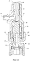
- Fig. 1C shows valve 100 during the carbonation process when there is a need to vent excess gas due to a pressure build up and
- Fig. 1D shows valve 100 during the carbonation process when there is a need to vent excess gas and there is blockage of the flow of gas and/or restrictive movement of its elements as described in herein above.
- Valve 100 comprises a valve carrier 10, a plunger 20, a spring nut 30, a burst disk housing 40, a valve body nut 60 and a spring 90.
- Housing 10 may further comprise an inlet 17 to allow the entry of excess gas, a hollow area 15, a conduit 12, a base area 45 and a safety outlet 95.
- Plunger 20 may comprise an O-ring 25 to ensure that no gas may escape between plunger 20 and the walls of valve carrier 10.
- Housing 40 may comprise a disk assembly 70 further comprising a burst disk 80 as described in detail herein below.
- valve 100 in its static state as is illustrated in Fig, 1A , valve 100 is closed, spring 90 is uncompressed and spring nut 30 holds housing 40 in place so that valve body nut 60 rests on base area 45 ensuring that valve sealing area 50 is totally sealed. Plunger 20 may also rest on the top of housing 40. Thus any gas entering valve 100 via inlet 17 may remain within valve 100 and may not be able to escape.
- valve 100 may be opened by pushing plunger 20 inwards as is illustrated in Fig. 1B to which reference is now made in order to release excess gas that may build up. It will be appreciated that this may be done mechanically by a cam 35 or another part automatically as part of the carbonation process.
- housing 40 When plunger 20 is depressed, the force against housing 40 may cause spring nut 30 to push downwards on spring 90. Spring 90 may be compressed allowing housing 40 to move downwards. It will be appreciated that the movement of housing 40 downwards may open sealing area 50 between valve body nut 60 and base area 45 since valve body nut 60 may remain in place. Thus any excess gas entering valve 100 via inlet 17 may flow through valve 100 and exit via the area between the opened sealing area 50 as is illustrated by the arrows. It will be appreciated that when carbonation is complete, plunger 20 may be released from its mechanical lock and spring 90 may return both housing 40 and plunger 20 to their normally closed positions.
- Fig. 1C illustrates valve 100 in the scenario when valve 100 is in a normally closed position and there is a buildup of excess pressure within the pertinent carbonation system.
- plunger 20 may remain in position since in this scenario valve 100 is closed and there is no intention to open it by depressing plunger 20.
- Excess gas may enter via inlet 17 as described herein above.
- the pressure of the entering gas pushes housing 40 downwards while plunger 20 remains in place.
- the downward force of housing 40 against spring nut 30 causes in turn said spring 90 to compress thus lowering housing 60 and opening sealing area 50 as described in herein above.
- Fig. 1D illustrates a typical scenario that may occur for example, when a non-water beverage is carbonated using the pertinent carbonation system.
- the splashing (as described herein above) may cause the non-water beverage being carbonated to enter valve 100 via inlet 17.
- the stickiness of the non-water beverage may for example, cause housing 40 and base area 45 to stick to valve body nut 60 restricting its downwards movement. Therefore in a scenario where valve 100 is closed and excess gas enters via inlet 17 as is illustrated in Fig. 1C , housing 40 may not be able to move downwards preventing sealing area 50 from opening up and thus valve 100 may remain closed.
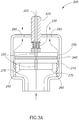
- a burst disc 80 may be held within burst disk housing 70 as is illustrated in Fig. 2 to which reference is now made.
- Burst disk housing 70 may comprise of a polymer ring 72 and a polymer enclosure 74. It will be further appreciated that burst disk 80 may be held tautly between polymer ring 72 and polymer enclosure 74.
- Burst disk 80 may be a membrane manufactured from nickel, stainless steel, plastic or any other suitable flexible material and may be configured to rupture whenever the pressure in valve 100 exceeds a set pressure point, for example a threshold pressure of 14-16 bars. It will be appreciated that the failure of sealing area 50 to open allows for this pressure build up within valve 100. When disc 80 ruptures, a new path is created via conduit 12 allowing gas to be released via hollow area 15, through ruptured burst disc 80, via safety outlet 95 and into the atmosphere as shown by the arrows in Fig. ID to which reference is now made.
- any liquid entering valve 100 during may be expelled via open sealing area 50 together with any excess gas as indicated by the arrows in Figs. IB and 1C and no malfunction of the of the pertinent carbonation machine may occur. It will be appreciated it is the aftermath of a first time carbonation of a non-water beverage that may leave a sticky layer behind which may cause parts to stick as described herein above.
- valve 100 may be considered self-purging or self-cleaning. Any liquid entering valve 100 due to splashing (as described here in above) can only flow the same way as the excess gas as indicated by the arrows in Figs. IB and 1C and at a substantial flow rate. It will be appreciated that the direction of and speed of flow of gas and liquid flowing through valve 100 may actually remove some of the stickiness that may have formed within the walls between carrier 10 and housing 40 and around sealing area 50 from a previous carbonation using a non-water beverage, thus decreasing the chances of sealing area 50 being unable to open to release excess gas if necessary.
- valve 100 may be a normally open valve 200 as is illustrated in Figs 3A , 3B , 3C and 3D .
- valve 200 is shown in its static normally open position.
- Fig. 3B shows valve 200 during the carbonation process when valve 200 is closed.
- Fig. 3C shows valve 200 during the carbonation process when there is a need to vent excess gas and
- Fig. 3D shows valve 200 during the carbonation process when there is a need to vent excess gas and there is blockage of the flow of gas and/or restrictive movement of its elements as described in herein above.
- Valve 200 comprises a housing 210, a hollow pin 220, a relief spring 230, a burst disk 240, a normally open plunger 250, a normally open spring 260 and a seal 270.
- Housing 210 may further comprise an outlet 290.
- Hollow pin 220 may comprise hollow area 225.
- Normally open plunger 250 may also comprise a hollow area 255 which may run through normally open plunger 250 but which may be blocked by the presence of burst disk 240.
- Relief spring 230 may allow normally open plunger 250 to move up and down within housing 210.
- valve 200 in its static state as is illustrated in Fig. 3A , valve 200 is open and normally open plunger 250 may be held in place by normally open spring 260. In this state, gas may freely flow through valve 200 and out through outlet 290 to the atmosphere as is illustrated by the arrows.
- hollow pin 220 may be pushed downwards via a cam 300 which may be part of the pertinent home carbonation system in use as is illustrated in Fig. 3B to which reference is now made.
- cam 300 may push hollow pin 220 downwards which may also apply a force to relief spring 230.
- the tension of relief spring 230 may be set so that the force applied by cam 300 and hollow pin 220 do not compress it, but instead push it downwards applying pressure to normally open plunger 250, which may also move downwards until it rests on seal 270, thus totally sealing valve 200. In this state, excess gas may not flow through seal 270 and instead, the only outlet may be via hollow area 255. As described herein above, hollow area 255 may be blocked by burst disc 240, preventing the flow of gas.
- Fig. 3C illustrates what happens to valve 200 when pressure build up in the bottle due to the carbonation process exceeds a required opening pressure of, for example 8 bars.
- the force of pressure of gas against normally open plunger 250 and in turn relief spring 230 may overcome the preset tension of relief spring 230 and may cause relief spring 230 to be compressed, thus allowing normally open plunger 250 to be pushed upwards by the pressure of the excess gas, even though hollow pin 220 is still in its downward state due to the continuing pressure applied by cam 300.
- This movement of normally open plunger 250 upwards may unseal valve 200 and may allow gas to freely flow through valve 200, via seal 270 and out through outlet 290 as indicated by the arrows in Fig. 3C .
- some gas may attempt to flow through hollow area 255 but burst disc 240 may block the gas from being released.
- Fig. 3D illustrates the scenario that may occur when a non-water beverage is carbonated using the pertinent carbonation system as is described herein above and the stickiness of a non-water beverage causes normally open plunger 250 to "stick" to the inside wall of housing 210, restricting the movement of normally open plunger 250 or in a situation when pressure starts to rise uncontrollably in the system. Therefore, when the gas entering valve 200 exceeds the required opening pressure of 8 bars, even though relief spring 230 may compress as described herein above, normally open plunger 250 may not move and valve 200 may remain closed.
- burst disc 240 may be configured to rupture whenever the pressure in valve 200 exceeds a set pressure point, for example a threshold pressure of 20 bars. When disc 240 ruptures gas may be released through the ruptured burst disc 20, via hollow areas 255 and 225 and into the atmosphere.
- burst disk 240 may be constructed and implemented as disk 80.
- a release valve incorporating a burst disc which may be ruptured at a high pressure may provide a backup solution for a safety valve when dealing with rising pressure during an uncontrollable carbonation process when, for whatever reason, the process continues past safe limits and when the regular release mechanism fails.
Landscapes
- Engineering & Computer Science (AREA)
- General Engineering & Computer Science (AREA)
- Mechanical Engineering (AREA)
- Chemical & Material Sciences (AREA)
- Chemical Kinetics & Catalysis (AREA)
- Safety Valves (AREA)
- Slot Machines And Peripheral Devices (AREA)
- Superconductors And Manufacturing Methods Therefor (AREA)
- Compressor (AREA)
Description
- The present invention relates to carbonation machines generally and to pressure release valves in particular.
- Soda machines for the carbonation of beverages are known in the art. Most such devices for home carbonation are designed for manual operation; typically comprising a manually operated gas release valve to release carbon dioxide (CO2) into a bottle of water from an attached pressurized cylinder. Such machines typically also comprise one or more safety pressure release valves which are designed to vent if excess pressure builds up during the carbonization process.
-
US 2562672 describes a combination pressure release and safety head valve with an annular valve seat and a cylindrical valving member engageable with the seat and of smaller diameter to provide a free annular passageway for the full length of the valving member, and in direct connection with the free annular passageway, a frangible diaphragm normally closing communication between an inlet port and an outlet port, and adapted to fracture for relief of pressure. - There is provided, in accordance with a preferred embodiment of the present invention, a safety unit for a home carbonation machine. The unit includes a valve to release gas from a sealed state at a first pressure; and a backup element set to rupture at a second higher pressure when said valve malfunctions; wherein said valve comprises a valve carrier, a spring nut, a spring and a backup element housing which moves to vent said gas via an outlet during carbonation; wherein said backup element housing has a conduit to direct said gas to said backup element; wherein said backup element is a burst disk; wherein pressure of the entering gas may push housing downwards, and the downward force of the housing against the spring nut may in turn cause the spring to compress thus lowering the housing and opening a sealing area; characterized in that, the valve comprises a valve body nut wherein in its static state, the valve is closed, the spring is uncompressed and the spring nut holds the housing in place so that the valve body nut rests on a base area of the housing ensuring that the sealing area is totally sealed.
- Moreover, in accordance with a preferred embodiment of the present invention, the burst disk includes a membrane manufactured from at least one of nickel, stainless steel and plastic.
- Further, in accordance with a preferred embodiment of the present invention, the backup element housing comprises two rings to hold the membrane.
- The subject matter regarded as the invention is particularly pointed out and distinctly claimed in the concluding portion of the specification. The invention, however, both as to organization and method of operation, together with objects, features, and advantages thereof, may best be understood by reference to the following detailed description when read with the accompanying drawings in which:
-
Figs. 1A , IB, IC and ID are schematic illustrations of a normally closed burst disk protected safety release valve, designed and operative in accordance with a preferred embodiment of the present invention; -
Fig. 2 is a schematic illustration of a burst disk assembly; and -
Figs. 3A ,3B ,3C and3D are schematic illustrations of a normally open burst disk protected safety release valve, designed and operative, and not forming part of the present invention. - It will be appreciated that for simplicity and clarity of illustration, elements shown in the figures have not necessarily been drawn to scale. For example, the dimensions of some of the elements may be exaggerated relative to other elements for clarity. Further, where considered appropriate, reference numerals may be repeated among the figures to indicate corresponding or analogous elements.
- In the following detailed description, numerous specific details are set forth in order to provide a thorough understanding of the invention. However, it will be understood by those skilled in the art that the present invention may be practiced without these specific details. In other instances, well-known methods, procedures, and components have not been described in detail so as not to obscure the present invention.
- Applicants have realized that although the soda machines discussed in the background are intended to be used with water only, users may also attempt (intentionally and un intentionally) to carbonate non-water beverages such as wine or orange juice or re-carbonate fizzy drinks that have gone flat.
- It will be appreciated as is described in the background, that typical soda machines also incorporate safety pressure release valves. These valves, such as that described in
US Patent Application 13/570,294 filed August 9, 2012 US Patent Application 13/570,294 - During the carbonation process, due to the addition of carbon dioxide, minimal splashing of the liquid that is being carbonated is inevitable. This splashing may cause small amounts of the liquid in question to reach/enter elements of the pertinent carbonation system such as the safety release valve. Applicants have realized that this splashing in relation to water is harmless and may be ignored, but that splashing of other beverages may potentially cause blockages to elements due to the level of sugar contained within. The sugar may "stick" to these elements, often forming a sticky layer. This sticky layer may restrict the movement of these elements and may also block the flow of gas. It will be appreciated that restricting the movement of elements in safety valves and blocking the flow of gas may cause pressure build up within the bottle of liquid which in turn may cause an uncontrolled explosion of the bottle under pressure.
- Applicants have further realized that, since the purpose of such safety pressure release valves is to provide a backup gas release system during the carbonation process, a secondary backup gas release system may be desirable when non-water beverages are being carbonated and there is a danger of impaired functionality of the safety pressure release valve due to the restrictive movements of its elements or if for any other reason, pressure starts to rise uncontrollably in the carbonating bottle.
- Reference is now made to
Figs. 1A ,1B ,1C and1D which illustrate a burst disk protectedsafety release valve 100 in accordance with an embodiment of the present invention. InFig. 1A valve 100 is shown in its static normally closed position.Fig. 1B showsvalve 100 in its open state before and after carbonation.Fig. 1C showsvalve 100 during the carbonation process when there is a need to vent excess gas due to a pressure build up andFig. 1D showsvalve 100 during the carbonation process when there is a need to vent excess gas and there is blockage of the flow of gas and/or restrictive movement of its elements as described in herein above. - Valve 100 comprises a
valve carrier 10, aplunger 20, aspring nut 30, aburst disk housing 40, avalve body nut 60 and aspring 90.Housing 10 may further comprise aninlet 17 to allow the entry of excess gas, ahollow area 15, aconduit 12, abase area 45 and asafety outlet 95.Plunger 20 may comprise an O-ring 25 to ensure that no gas may escape betweenplunger 20 and the walls ofvalve carrier 10.Housing 40 may comprise adisk assembly 70 further comprising aburst disk 80 as described in detail herein below. - It will be appreciated that in its static state as is illustrated in
Fig, 1A ,valve 100 is closed,spring 90 is uncompressed andspring nut 30 holdshousing 40 in place so thatvalve body nut 60 rests onbase area 45 ensuring thatvalve sealing area 50 is totally sealed.Plunger 20 may also rest on the top ofhousing 40. Thus anygas entering valve 100 viainlet 17 may remain withinvalve 100 and may not be able to escape. During the carbonation process,valve 100 may be opened by pushingplunger 20 inwards as is illustrated inFig. 1B to which reference is now made in order to release excess gas that may build up. It will be appreciated that this may be done mechanically by acam 35 or another part automatically as part of the carbonation process. - When
plunger 20 is depressed, the force againsthousing 40 may causespring nut 30 to push downwards onspring 90.Spring 90 may be compressed allowinghousing 40 to move downwards. It will be appreciated that the movement ofhousing 40 downwards may opensealing area 50 betweenvalve body nut 60 andbase area 45 sincevalve body nut 60 may remain in place. Thus any excessgas entering valve 100 viainlet 17 may flow throughvalve 100 and exit via the area between the openedsealing area 50 as is illustrated by the arrows. It will be appreciated that when carbonation is complete,plunger 20 may be released from its mechanical lock andspring 90 may return bothhousing 40 and plunger 20 to their normally closed positions. - Reference is now made to
Fig. 1C which illustratesvalve 100 in the scenario whenvalve 100 is in a normally closed position and there is a buildup of excess pressure within the pertinent carbonation system. It will be appreciated thatplunger 20 may remain in position since in thisscenario valve 100 is closed and there is no intention to open it by depressingplunger 20. Excess gas may enter viainlet 17 as described herein above. The pressure of the entering gas pusheshousing 40 downwards whileplunger 20 remains in place. The downward force ofhousing 40 againstspring nut 30 causes in turn saidspring 90 to compress thus loweringhousing 60 andopening sealing area 50 as described in herein above. - Reference is now made to
Fig. 1D which illustrates a typical scenario that may occur for example, when a non-water beverage is carbonated using the pertinent carbonation system. It will be appreciated that the splashing (as described herein above) may cause the non-water beverage being carbonated to entervalve 100 viainlet 17. As described herein above, the stickiness of the non-water beverage may for example, causehousing 40 andbase area 45 to stick tovalve body nut 60 restricting its downwards movement. Therefore in a scenario wherevalve 100 is closed and excess gas enters viainlet 17 as is illustrated inFig. 1C ,housing 40 may not be able to move downwards preventingsealing area 50 from opening up and thusvalve 100 may remain closed. It will be appreciated that in a non-carbonation mode, this may not be so critical since there is no gas to vent, but in carbonation mode this could be dangerous. If the pressure build up within the bottle is too great (for example 20 bars) and there is no means to vent it due to the blocked valve, an uncontrolled explosion of the bottle in which carbonation is taking place may occur. - In accordance with a preferred embodiment of the present invention, a
burst disc 80 may be held within burstdisk housing 70 as is illustrated inFig. 2 to which reference is now made.Burst disk housing 70 may comprise of apolymer ring 72 and apolymer enclosure 74. It will be further appreciated that burstdisk 80 may be held tautly betweenpolymer ring 72 andpolymer enclosure 74. -
Burst disk 80 may be a membrane manufactured from nickel, stainless steel, plastic or any other suitable flexible material and may be configured to rupture whenever the pressure invalve 100 exceeds a set pressure point, for example a threshold pressure of 14-16 bars. It will be appreciated that the failure of sealingarea 50 to open allows for this pressure build up withinvalve 100. Whendisc 80 ruptures, a new path is created viaconduit 12 allowing gas to be released viahollow area 15, through rupturedburst disc 80, viasafety outlet 95 and into the atmosphere as shown by the arrows in Fig. ID to which reference is now made. - It will be appreciated that the first time carbonation is performed on a non-water beverage, any
liquid entering valve 100 during may be expelled viaopen sealing area 50 together with any excess gas as indicated by the arrows in Figs. IB and 1C and no malfunction of the of the pertinent carbonation machine may occur. It will be appreciated it is the aftermath of a first time carbonation of a non-water beverage that may leave a sticky layer behind which may cause parts to stick as described herein above. - It will also be appreciated that
valve 100 may be considered self-purging or self-cleaning. Anyliquid entering valve 100 due to splashing (as described here in above) can only flow the same way as the excess gas as indicated by the arrows in Figs. IB and 1C and at a substantial flow rate. It will be appreciated that the direction of and speed of flow of gas and liquid flowing throughvalve 100 may actually remove some of the stickiness that may have formed within the walls betweencarrier 10 andhousing 40 and around sealingarea 50 from a previous carbonation using a non-water beverage, thus decreasing the chances of sealingarea 50 being unable to open to release excess gas if necessary. - In an alternative example, not forming part of the present invention,
valve 100 may be a normallyopen valve 200 as is illustrated inFigs 3A ,3B ,3C and3D . InFig. 3A valve 200 is shown in its static normally open position.Fig. 3B showsvalve 200 during the carbonation process whenvalve 200 is closed.Fig. 3C showsvalve 200 during the carbonation process when there is a need to vent excess gas andFig. 3D showsvalve 200 during the carbonation process when there is a need to vent excess gas
and there is blockage of the flow of gas and/or restrictive movement of its elements as described in herein above. -
Valve 200 comprises ahousing 210, ahollow pin 220, arelief spring 230, aburst disk 240, a normallyopen plunger 250, a normallyopen spring 260 and aseal 270.Housing 210 may further comprise anoutlet 290.Hollow pin 220 may comprisehollow area 225. Normallyopen plunger 250 may also comprise ahollow area 255 which may run through normallyopen plunger 250 but which may be blocked by the presence ofburst disk 240.Relief spring 230 may allow normallyopen plunger 250 to move up and down withinhousing 210. - It will be appreciated that in its static state as is illustrated in
Fig. 3A ,valve 200 is open and normallyopen plunger 250 may be held in place by normallyopen spring 260. In this state, gas may freely flow throughvalve 200 and out throughoutlet 290 to the atmosphere as is illustrated by the arrows. - During carbonation,
hollow pin 220 may be pushed downwards via acam 300 which may be part of the pertinent home carbonation system in use as is illustrated inFig. 3B to which reference is now made. It will be appreciated that the force applied tohollow pin 220 bycam 300 may pushhollow pin 220 downwards which may also apply a force torelief spring 230. It will be also appreciated that the tension ofrelief spring 230 may be set so that the force applied bycam 300 andhollow pin 220 do not compress it, but instead push it downwards applying pressure to normallyopen plunger 250, which may also move downwards until it rests onseal 270, thus totally sealingvalve 200. In this state, excess gas may not flow throughseal 270 and instead, the only outlet may be viahollow area 255. As described herein above,hollow area 255 may be blocked byburst disc 240, preventing the flow of gas. - Reference is now made to
Fig. 3C which illustrates what happens tovalve 200 when pressure build up in the bottle due to the carbonation process exceeds a required opening pressure of, for example 8 bars. It will be appreciated that the force of pressure of gas against normallyopen plunger 250 and inturn relief spring 230 may overcome the preset tension ofrelief spring 230 and may causerelief spring 230 to be compressed, thus allowing normallyopen plunger 250 to be pushed upwards by the pressure of the excess gas, even thoughhollow pin 220 is still in its downward state due to the continuing pressure applied bycam 300. This movement of normallyopen plunger 250 upwards may unsealvalve 200 and may allow gas to freely flow throughvalve 200, viaseal 270 and out throughoutlet 290 as indicated by the arrows inFig. 3C . It will also be appreciated that some gas may attempt to flow throughhollow area 255 but burstdisc 240 may block the gas from being released. - Reference is now made to
Fig. 3D which illustrates the scenario that may occur when a non-water beverage is carbonated using the pertinent carbonation system as is described herein above and the stickiness of a non-water beverage causes normallyopen plunger 250 to "stick" to the inside wall ofhousing 210, restricting the movement of normallyopen plunger 250 or in a situation when pressure starts to rise uncontrollably in the system. Therefore, when thegas entering valve 200 exceeds the required opening pressure of 8 bars, even thoughrelief spring 230 may compress as described herein above, normallyopen plunger 250 may not move andvalve 200 may remain closed. - As described herein above,
burst disc 240 may be configured to rupture whenever the pressure invalve 200 exceeds a set pressure point, for example a threshold pressure of 20 bars. Whendisc 240 ruptures gas may be released through theruptured burst disc 20, viahollow areas - It will be appreciated that
burst disk 240 may be constructed and implemented asdisk 80. - Thus, a release valve incorporating a burst disc which may be ruptured at a high pressure, may provide a backup solution for a safety valve when dealing with rising pressure during an uncontrollable carbonation process when, for whatever reason, the process continues past safe limits and when the regular release mechanism fails.
Claims (4)
- A safety unit for a home carbonation machine, the unit comprising:a valve (100) to release gas from a sealed state at a first pressure; anda backup element set to rupture at a second higher pressure when said valve malfunctions;wherein said valve comprises a valve carrier (10), a spring nut (30), a spring (90) and a backup element housing (40) which moves to vent said gas via an outlet during carbonation;wherein said backup element housing (40) has a conduit (12) to direct said gas to said backup element;wherein said backup element is a burst disk (80);wherein pressure of the entering gas pushes housing (40) downwards, and the downward force of the housing (40) against the spring nut (30 causes in turn said spring (90) to compress thus lowering the housing (40) and opening a sealing area (50),and wherein the failure of the sealing area (50) to open allows for a pressure build up within valve (100) and, when disc (80) ruptures, a new path is created via conduit (12) allowing gas to be released via a hollow area (15) through ruptured burst disc (80), via safety outlet (95) and into the atmosphere,characterized in that,the valve comprises a valve body nut (60)wherein in its static state, the valve (100) is closed, the spring (90) is uncompressed and the spring nut (30) holds the housing (40) in place so that the valve body nut (60) rests on a base area (45) of the housing (40) ensuring that the sealing area (50) is totally sealed.
- The safety unit of claim 1 and wherein said backup element housing (40) has a secondary outlet (95) to vent said excess gas after said backup element is ruptured.
- The safety unit of claim 1 and wherein said burst disk (80) comprises a membrane manufactured from at least one of nickel, stainless steel and plastic.
- The safety unit of claim 3 and wherein said backup element housing (40) comprises a ring (72) and an enclosure (74) to hold said membrane.
Priority Applications (5)
| Application Number | Priority Date | Filing Date | Title |
|---|---|---|---|
| SI201431197T SI3033296T1 (en) | 2013-08-12 | 2014-08-11 | Burst disk protected valve |
| SM20190250T SMT201900250T1 (en) | 2013-08-12 | 2014-08-11 | Burst disk protected valve |
| RS20190491A RS58789B1 (en) | 2013-08-12 | 2014-08-11 | Burst disk protected valve |
| PL14836343T PL3033296T3 (en) | 2013-08-12 | 2014-08-11 | Burst disk protected valve |
| HRP20190718TT HRP20190718T1 (en) | 2013-08-12 | 2014-08-11 | Burst disk protected valve |
Applications Claiming Priority (3)
| Application Number | Priority Date | Filing Date | Title |
|---|---|---|---|
| US201361864660P | 2013-08-12 | 2013-08-12 | |
| US201361911500P | 2013-12-04 | 2013-12-04 | |
| PCT/IB2014/063845 WO2015022619A1 (en) | 2013-08-12 | 2014-08-11 | Burst disk protected valve |
Publications (3)
| Publication Number | Publication Date |
|---|---|
| EP3033296A1 EP3033296A1 (en) | 2016-06-22 |
| EP3033296A4 EP3033296A4 (en) | 2017-04-19 |
| EP3033296B1 true EP3033296B1 (en) | 2019-04-03 |
Family
ID=52447555
Family Applications (1)
| Application Number | Title | Priority Date | Filing Date |
|---|---|---|---|
| EP14836343.5A Active EP3033296B1 (en) | 2013-08-12 | 2014-08-11 | Burst disk protected valve |
Country Status (15)
| Country | Link |
|---|---|
| US (1) | US9897220B2 (en) |
| EP (1) | EP3033296B1 (en) |
| CN (1) | CN105579388B (en) |
| CY (1) | CY1121616T1 (en) |
| DK (1) | DK3033296T3 (en) |
| ES (1) | ES2725434T3 (en) |
| HR (1) | HRP20190718T1 (en) |
| HU (1) | HUE043388T2 (en) |
| LT (1) | LT3033296T (en) |
| PL (1) | PL3033296T3 (en) |
| PT (1) | PT3033296T (en) |
| RS (1) | RS58789B1 (en) |
| SI (1) | SI3033296T1 (en) |
| SM (1) | SMT201900250T1 (en) |
| WO (1) | WO2015022619A1 (en) |
Families Citing this family (24)
| Publication number | Priority date | Publication date | Assignee | Title |
|---|---|---|---|---|
| US11448210B2 (en) | 2015-07-02 | 2022-09-20 | Spm Oil & Gas Inc. | Valve for reciprocating pump assembly |
| US10221848B2 (en) * | 2015-07-02 | 2019-03-05 | S.P.M. Flow Control, Inc. | Valve for reciprocating pump assembly |
| FR3082921B1 (en) * | 2018-06-26 | 2020-05-29 | Safran Electronics & Defense | JOULE-THOMSON COOLER AND METHOD OF MANUFACTURING SUCH A COOLER |
| US12259051B2 (en) * | 2021-04-07 | 2025-03-25 | Honeywell International Inc. | Pressure release housing |
| US11647860B1 (en) | 2022-05-13 | 2023-05-16 | Sharkninja Operating Llc | Flavored beverage carbonation system |
| US12096880B2 (en) | 2022-05-13 | 2024-09-24 | Sharkninja Operating Llc | Flavorant for beverage carbonation system |
| US12213617B2 (en) | 2022-05-13 | 2025-02-04 | Sharkninja Operating Llc | Flavored beverage carbonation process |
| CN119403454A (en) | 2022-05-13 | 2025-02-07 | 尚科宁家运营有限公司 | Agitators for carbonation systems |
| US11751585B1 (en) | 2022-05-13 | 2023-09-12 | Sharkninja Operating Llc | Flavored beverage carbonation system |
| US12005404B2 (en) | 2022-08-22 | 2024-06-11 | Sharkninja Operating Llc | Beverage carbonation system flow control |
| US12539500B2 (en) | 2022-08-31 | 2026-02-03 | Sharkninja Operating Llc | Additive containers |
| US11738988B1 (en) | 2022-11-17 | 2023-08-29 | Sharkninja Operating Llc | Ingredient container valve control |
| US12103840B2 (en) | 2022-11-17 | 2024-10-01 | Sharkninja Operating Llc | Ingredient container with sealing valve |
| US11634314B1 (en) | 2022-11-17 | 2023-04-25 | Sharkninja Operating Llc | Dosing accuracy |
| US11745996B1 (en) | 2022-11-17 | 2023-09-05 | Sharkninja Operating Llc | Ingredient containers for use with beverage dispensers |
| US12084334B2 (en) | 2022-11-17 | 2024-09-10 | Sharkninja Operating Llc | Ingredient container |
| USD1091308S1 (en) | 2022-12-23 | 2025-09-02 | Sharkninja Operating Llc | Ingredient container |
| USD1092208S1 (en) | 2022-12-23 | 2025-09-09 | Sharkninja Operating Llc | Cap of ingredient container |
| US11871867B1 (en) | 2023-03-22 | 2024-01-16 | Sharkninja Operating Llc | Additive container with bottom cover |
| US12116257B1 (en) | 2023-03-22 | 2024-10-15 | Sharkninja Operating Llc | Adapter for beverage dispenser |
| US11925287B1 (en) | 2023-03-22 | 2024-03-12 | Sharkninja Operating Llc | Additive container with inlet tube |
| US12005408B1 (en) | 2023-04-14 | 2024-06-11 | Sharkninja Operating Llc | Mixing funnel |
| WO2024254837A1 (en) | 2023-06-16 | 2024-12-19 | Sharkninja Operating Llc | Carbonation mixing nozzles |
| US20250057357A1 (en) * | 2023-08-14 | 2025-02-20 | Sodastream Industries Ltd. | Carbonation machine |
Family Cites Families (33)
| Publication number | Priority date | Publication date | Assignee | Title |
|---|---|---|---|---|
| USRE19087E (en) * | 1934-02-20 | Valve | ||
| US1571022A (en) * | 1923-03-21 | 1926-01-26 | Casin W Obert | Pressure-relief device |
| US2562672A (en) * | 1946-12-11 | 1951-07-31 | Black Sivalls & Bryson Inc | Combination pressure relief and safety head valve |
| US3693644A (en) * | 1971-05-20 | 1972-09-26 | Gen Motors Corp | Pressure vessel fill and pressure relief valve |
| US3834412A (en) * | 1973-06-25 | 1974-09-10 | Gen Motors Corp | Combined fill, pressure relief and bleed valve assembly for pressure vessels |
| US4064890A (en) * | 1975-06-23 | 1977-12-27 | Air Products And Chemicals, Inc. | Pressure regulator and safety relief valve |
| GB2036905B (en) * | 1978-12-11 | 1983-01-12 | Boc Ltd | Fluid storage vessels |
| FR2460434A1 (en) * | 1979-06-28 | 1981-01-23 | Commissariat Energie Atomique | AUTOMATIC PURGE SAFETY VALVE |
| US4352365A (en) * | 1979-11-01 | 1982-10-05 | The Commonwealth Industrial Gases Limited | Pressure vessel safety valve |
| GB2068757B (en) * | 1980-01-15 | 1983-03-02 | Sodastream Ltd | Apparatus for aerating liquids |
| US4687421A (en) * | 1982-12-06 | 1987-08-18 | Dowell Schlumberger Incorporated | Frangible pressure relief disc assembly and positive displacement pumps containing the disc assembly |
| IL71353A (en) * | 1983-04-08 | 1987-10-20 | Sodastream Ltd | Liquid carbonating apparatus |
| CA1265990A (en) | 1984-10-08 | 1990-02-20 | Neil K. Sutherland | Domestic carbonator |
| US5031799A (en) | 1989-02-17 | 1991-07-16 | Charlie O Company, Inc. | Seltzer dispenser for use with a home soda dispensing system |
| US6145595A (en) * | 1998-10-05 | 2000-11-14 | Halliburton Energy Services, Inc. | Annulus pressure referenced circulating valve |
| US6148841A (en) * | 1999-07-08 | 2000-11-21 | Davidson; Gilbert | High pressure gas valve |
| DE19959770A1 (en) * | 1999-12-11 | 2001-09-13 | Brita Gmbh | Bubbler |
| US6240951B1 (en) * | 1999-12-31 | 2001-06-05 | The B. F. Goodrich Company | Inflation system and valve for use therein |
| DE10251803A1 (en) * | 2002-11-07 | 2004-11-11 | Luk Fahrzeug-Hydraulik Gmbh & Co Kg | compressor |
| CN1183346C (en) * | 2002-11-26 | 2005-01-05 | 大连理工大学 | Normally open pilot operated safety valve combined with rupture disc |
| US7051751B2 (en) * | 2003-12-05 | 2006-05-30 | Pressure Spcacialist, Inc. | Burst disk assembly |
| CA2569830A1 (en) * | 2004-03-04 | 2005-09-22 | Avox Systems, Inc. | Breathing gas dispenser with selectable output flow rates |
| GB0411295D0 (en) * | 2004-05-20 | 2004-06-23 | Interbrew Sa | Alcohol beverage apparatus having a bursting disk |
| US6948698B1 (en) * | 2004-06-18 | 2005-09-27 | Eric Scott | Valve for pressurized canister |
| EP1642637A1 (en) * | 2004-09-29 | 2006-04-05 | Soda-Club Ltd | A device for carbonating a liquid with pressurized gas |
| GB0619443D0 (en) * | 2006-10-02 | 2006-11-08 | Airbus Uk Ltd | A valve |
| SE534464C2 (en) * | 2009-06-12 | 2011-08-30 | Torsten Aake Adrian Ottoson | Apparatus for adding a gas to a liquid-filled bottle |
| GB2472589B (en) * | 2009-08-11 | 2011-09-07 | Siemens Magnet Technology Ltd | Quench path for cryogen vessel for containing a superconducting magnet |
| GB2477756A (en) * | 2010-02-11 | 2011-08-17 | Ingazzi Ltd | A carbonating apparatus |
| EP3040114B1 (en) | 2011-08-10 | 2019-03-13 | SodaStream Industries Ltd. | Home use carbonation machine |
| KR101395796B1 (en) * | 2012-01-06 | 2014-05-19 | 주식회사 포스코 | Carbonation apparatus and carbonation method using same |
| US8978685B2 (en) * | 2012-02-08 | 2015-03-17 | Conair Corporation | Valve assembly for compressed air cartridge |
| CN202972064U (en) * | 2012-12-29 | 2013-06-05 | 宁波三安制阀有限公司 | Cylinder head valve |
-
2014
- 2014-08-11 RS RS20190491A patent/RS58789B1/en unknown
- 2014-08-11 WO PCT/IB2014/063845 patent/WO2015022619A1/en not_active Ceased
- 2014-08-11 SM SM20190250T patent/SMT201900250T1/en unknown
- 2014-08-11 US US14/455,950 patent/US9897220B2/en active Active
- 2014-08-11 LT LTEP14836343.5T patent/LT3033296T/en unknown
- 2014-08-11 SI SI201431197T patent/SI3033296T1/en unknown
- 2014-08-11 PL PL14836343T patent/PL3033296T3/en unknown
- 2014-08-11 HU HUE14836343A patent/HUE043388T2/en unknown
- 2014-08-11 EP EP14836343.5A patent/EP3033296B1/en active Active
- 2014-08-11 DK DK14836343.5T patent/DK3033296T3/en active
- 2014-08-11 PT PT14836343T patent/PT3033296T/en unknown
- 2014-08-11 CN CN201480048589.0A patent/CN105579388B/en active Active
- 2014-08-11 HR HRP20190718TT patent/HRP20190718T1/en unknown
- 2014-08-11 ES ES14836343T patent/ES2725434T3/en active Active
-
2019
- 2019-05-02 CY CY20191100462T patent/CY1121616T1/en unknown
Non-Patent Citations (1)
| Title |
|---|
| None * |
Also Published As
| Publication number | Publication date |
|---|---|
| RS58789B1 (en) | 2019-07-31 |
| CN105579388B (en) | 2018-06-01 |
| EP3033296A1 (en) | 2016-06-22 |
| US20150040991A1 (en) | 2015-02-12 |
| DK3033296T3 (en) | 2019-05-13 |
| HRP20190718T1 (en) | 2019-08-23 |
| PL3033296T3 (en) | 2019-09-30 |
| LT3033296T (en) | 2019-07-25 |
| US9897220B2 (en) | 2018-02-20 |
| CY1121616T1 (en) | 2020-07-31 |
| SI3033296T1 (en) | 2019-08-30 |
| ES2725434T3 (en) | 2019-09-24 |
| PT3033296T (en) | 2019-05-29 |
| HUE043388T2 (en) | 2019-08-28 |
| EP3033296A4 (en) | 2017-04-19 |
| WO2015022619A1 (en) | 2015-02-19 |
| CN105579388A (en) | 2016-05-11 |
| SMT201900250T1 (en) | 2019-07-11 |
Similar Documents
| Publication | Publication Date | Title |
|---|---|---|
| US9897220B2 (en) | Burst disk protected valve | |
| US20230303312A1 (en) | Beverage container having a pressure-relief device and a method of manufacturing a beverage container having a pressure-relief device | |
| CN103003171B (en) | Self-cooling beverage container with overpressure release valve | |
| EP3022148B1 (en) | Overpressure valve of a spear tube valve | |
| JP5767251B2 (en) | Carbonator, carbonator, associated discharge assembly, associated cap assembly, and method for carbonated in a container | |
| US4566476A (en) | Flow control device | |
| WO2017031584A1 (en) | Demountable coupler valve for one-way kegs | |
| US11261983B2 (en) | Safety valve | |
| CN115279665B (en) | Beverage container stoppers and pressurization systems | |
| EP3678986B1 (en) | Valve closure incorporating an over-pressure relief valve | |
| US4913184A (en) | Flow control device | |
| EP2563714B1 (en) | Dispense head for a draft beverage dispensing system | |
| EP3329159B1 (en) | Valve | |
| JP4530480B2 (en) | Opened bottled beverage processing device | |
| EP2540660B1 (en) | Beverage dispensing system | |
| US20240226822A9 (en) | Apparatus for carbonating a liquid in a bottle | |
| HK40082560B (en) | Beverage container stopper and pressurization system | |
| HK40082560A (en) | Beverage container stopper and pressurization system | |
| EA038515B1 (en) | Beverage container having a pressure-relief device and method of manufacturing a beverage container having a pressure-relief device | |
| HK1177613B (en) | A self chilling beverage container having an over pressure relief valve |
Legal Events
| Date | Code | Title | Description |
|---|---|---|---|
| PUAI | Public reference made under article 153(3) epc to a published international application that has entered the european phase |
Free format text: ORIGINAL CODE: 0009012 |
|
| 17P | Request for examination filed |
Effective date: 20160301 |
|
| AK | Designated contracting states |
Kind code of ref document: A1 Designated state(s): AL AT BE BG CH CY CZ DE DK EE ES FI FR GB GR HR HU IE IS IT LI LT LU LV MC MK MT NL NO PL PT RO RS SE SI SK SM TR |
|
| AX | Request for extension of the european patent |
Extension state: BA ME |
|
| DAX | Request for extension of the european patent (deleted) | ||
| A4 | Supplementary search report drawn up and despatched |
Effective date: 20170317 |
|
| RIC1 | Information provided on ipc code assigned before grant |
Ipc: F16K 17/16 20060101ALI20170313BHEP Ipc: B67D 1/04 20060101AFI20170313BHEP Ipc: F16K 17/04 20060101ALI20170313BHEP Ipc: B01F 3/04 20060101ALI20170313BHEP |
|
| STAA | Information on the status of an ep patent application or granted ep patent |
Free format text: STATUS: EXAMINATION IS IN PROGRESS |
|
| 17Q | First examination report despatched |
Effective date: 20171204 |
|
| GRAP | Despatch of communication of intention to grant a patent |
Free format text: ORIGINAL CODE: EPIDOSNIGR1 |
|
| STAA | Information on the status of an ep patent application or granted ep patent |
Free format text: STATUS: GRANT OF PATENT IS INTENDED |
|
| INTG | Intention to grant announced |
Effective date: 20181105 |
|
| RAP1 | Party data changed (applicant data changed or rights of an application transferred) |
Owner name: SODASTREAM INDUSTRIES LTD. |
|
| GRAS | Grant fee paid |
Free format text: ORIGINAL CODE: EPIDOSNIGR3 |
|
| GRAA | (expected) grant |
Free format text: ORIGINAL CODE: 0009210 |
|
| STAA | Information on the status of an ep patent application or granted ep patent |
Free format text: STATUS: THE PATENT HAS BEEN GRANTED |
|
| AK | Designated contracting states |
Kind code of ref document: B1 Designated state(s): AL AT BE BG CH CY CZ DE DK EE ES FI FR GB GR HR HU IE IS IT LI LT LU LV MC MK MT NL NO PL PT RO RS SE SI SK SM TR |
|
| REG | Reference to a national code |
Ref country code: GB Ref legal event code: FG4D |
|
| REG | Reference to a national code |
Ref country code: AT Ref legal event code: REF Ref document number: 1115486 Country of ref document: AT Kind code of ref document: T Effective date: 20190415 Ref country code: CH Ref legal event code: EP |
|
| REG | Reference to a national code |
Ref country code: HR Ref legal event code: TUEP Ref document number: P20190718 Country of ref document: HR |
|
| REG | Reference to a national code |
Ref country code: DE Ref legal event code: R096 Ref document number: 602014044149 Country of ref document: DE Ref country code: RO Ref legal event code: EPE |
|
| REG | Reference to a national code |
Ref country code: IE Ref legal event code: FG4D |
|
| REG | Reference to a national code |
Ref country code: DK Ref legal event code: T3 Effective date: 20190510 |
|
| REG | Reference to a national code |
Ref country code: NL Ref legal event code: FP |
|
| REG | Reference to a national code |
Ref country code: SE Ref legal event code: TRGR |
|
| REG | Reference to a national code |
Ref country code: PT Ref legal event code: SC4A Ref document number: 3033296 Country of ref document: PT Date of ref document: 20190529 Kind code of ref document: T Free format text: AVAILABILITY OF NATIONAL TRANSLATION Effective date: 20190503 |
|
| REG | Reference to a national code |
Ref country code: CH Ref legal event code: NV Representative=s name: VALIPAT S.A. C/O BOVARD SA NEUCHATEL, CH |
|
| REG | Reference to a national code |
Ref country code: NO Ref legal event code: T2 Effective date: 20190403 |
|
| REG | Reference to a national code |
Ref country code: EE Ref legal event code: FG4A Ref document number: E017444 Country of ref document: EE Effective date: 20190506 |
|
| REG | Reference to a national code |
Ref country code: HR Ref legal event code: T1PR Ref document number: P20190718 Country of ref document: HR Ref country code: HR Ref legal event code: ODRP Ref document number: P20190718 Country of ref document: HR Payment date: 20190807 Year of fee payment: 6 |
|
| REG | Reference to a national code |
Ref country code: GR Ref legal event code: EP Ref document number: 20190401552 Country of ref document: GR Effective date: 20190708 |
|
| REG | Reference to a national code |
Ref country code: HU Ref legal event code: AG4A Ref document number: E043388 Country of ref document: HU |
|
| REG | Reference to a national code |
Ref country code: SK Ref legal event code: T3 Ref document number: E 31163 Country of ref document: SK |
|
| REG | Reference to a national code |
Ref country code: ES Ref legal event code: FG2A Ref document number: 2725434 Country of ref document: ES Kind code of ref document: T3 Effective date: 20190924 |
|
| REG | Reference to a national code |
Ref country code: DE Ref legal event code: R097 Ref document number: 602014044149 Country of ref document: DE |
|
| PLBE | No opposition filed within time limit |
Free format text: ORIGINAL CODE: 0009261 |
|
| STAA | Information on the status of an ep patent application or granted ep patent |
Free format text: STATUS: NO OPPOSITION FILED WITHIN TIME LIMIT |
|
| 26N | No opposition filed |
Effective date: 20200106 |
|
| REG | Reference to a national code |
Ref country code: HR Ref legal event code: ODRP Ref document number: P20190718 Country of ref document: HR Payment date: 20200731 Year of fee payment: 7 |
|
| REG | Reference to a national code |
Ref country code: EE Ref legal event code: HC1A Ref document number: E017444 Country of ref document: EE |
|
| REG | Reference to a national code |
Ref country code: AT Ref legal event code: UEP Ref document number: 1115486 Country of ref document: AT Kind code of ref document: T Effective date: 20190403 |
|
| REG | Reference to a national code |
Ref country code: HR Ref legal event code: ODRP Ref document number: P20190718 Country of ref document: HR Payment date: 20210727 Year of fee payment: 8 |
|
| REG | Reference to a national code |
Ref country code: HR Ref legal event code: ODRP Ref document number: P20190718 Country of ref document: HR Payment date: 20220809 Year of fee payment: 9 |
|
| P01 | Opt-out of the competence of the unified patent court (upc) registered |
Effective date: 20230602 |
|
| REG | Reference to a national code |
Ref country code: HR Ref legal event code: ODRP Ref document number: P20190718 Country of ref document: HR Payment date: 20230728 Year of fee payment: 10 |
|
| REG | Reference to a national code |
Ref country code: HR Ref legal event code: ODRP Ref document number: P20190718 Country of ref document: HR Payment date: 20240626 Year of fee payment: 11 |
|
| PGFP | Annual fee paid to national office [announced via postgrant information from national office to epo] |
Ref country code: NL Payment date: 20250724 Year of fee payment: 12 Ref country code: LU Payment date: 20250725 Year of fee payment: 12 |
|
| REG | Reference to a national code |
Ref country code: HR Ref legal event code: ODRP Ref document number: P20190718 Country of ref document: HR Payment date: 20250730 Year of fee payment: 12 |
|
| PGFP | Annual fee paid to national office [announced via postgrant information from national office to epo] |
Ref country code: HU Payment date: 20250813 Year of fee payment: 12 |
|
| PGFP | Annual fee paid to national office [announced via postgrant information from national office to epo] |
Ref country code: SM Payment date: 20250730 Year of fee payment: 12 |
|
| PGFP | Annual fee paid to national office [announced via postgrant information from national office to epo] |
Ref country code: PT Payment date: 20250807 Year of fee payment: 12 Ref country code: ES Payment date: 20250905 Year of fee payment: 12 Ref country code: FI Payment date: 20250814 Year of fee payment: 12 |
|
| PGFP | Annual fee paid to national office [announced via postgrant information from national office to epo] |
Ref country code: LT Payment date: 20250723 Year of fee payment: 12 Ref country code: DK Payment date: 20250814 Year of fee payment: 12 Ref country code: DE Payment date: 20250722 Year of fee payment: 12 |
|
| PGFP | Annual fee paid to national office [announced via postgrant information from national office to epo] |
Ref country code: MC Payment date: 20250728 Year of fee payment: 12 Ref country code: GR Payment date: 20250725 Year of fee payment: 12 Ref country code: NO Payment date: 20250808 Year of fee payment: 12 |
|
| PGFP | Annual fee paid to national office [announced via postgrant information from national office to epo] |
Ref country code: TR Payment date: 20250729 Year of fee payment: 12 Ref country code: PL Payment date: 20250729 Year of fee payment: 12 Ref country code: IT Payment date: 20250728 Year of fee payment: 12 |
|
| PGFP | Annual fee paid to national office [announced via postgrant information from national office to epo] |
Ref country code: BG Payment date: 20250729 Year of fee payment: 12 Ref country code: BE Payment date: 20250724 Year of fee payment: 12 Ref country code: GB Payment date: 20250717 Year of fee payment: 12 |
|
| PGFP | Annual fee paid to national office [announced via postgrant information from national office to epo] |
Ref country code: HR Payment date: 20250730 Year of fee payment: 12 |
|
| PGFP | Annual fee paid to national office [announced via postgrant information from national office to epo] |
Ref country code: AL Payment date: 20250815 Year of fee payment: 12 Ref country code: FR Payment date: 20250721 Year of fee payment: 12 Ref country code: AT Payment date: 20250725 Year of fee payment: 12 |
|
| PGFP | Annual fee paid to national office [announced via postgrant information from national office to epo] |
Ref country code: CH Payment date: 20250901 Year of fee payment: 12 Ref country code: MT Payment date: 20250819 Year of fee payment: 12 Ref country code: SE Payment date: 20250728 Year of fee payment: 12 |
|
| PGFP | Annual fee paid to national office [announced via postgrant information from national office to epo] |
Ref country code: RS Payment date: 20250729 Year of fee payment: 12 Ref country code: EE Payment date: 20250730 Year of fee payment: 12 Ref country code: IE Payment date: 20250723 Year of fee payment: 12 Ref country code: CZ Payment date: 20250729 Year of fee payment: 12 |
|
| PGFP | Annual fee paid to national office [announced via postgrant information from national office to epo] |
Ref country code: RO Payment date: 20250728 Year of fee payment: 12 |
|
| PGFP | Annual fee paid to national office [announced via postgrant information from national office to epo] |
Ref country code: SK Payment date: 20250723 Year of fee payment: 12 |
|
| PGFP | Annual fee paid to national office [announced via postgrant information from national office to epo] |
Ref country code: IS Payment date: 20250811 Year of fee payment: 12 |
|
| PGFP | Annual fee paid to national office [announced via postgrant information from national office to epo] |
Ref country code: LV Payment date: 20250721 Year of fee payment: 12 |
|
| PGFP | Annual fee paid to national office [announced via postgrant information from national office to epo] |
Ref country code: SI Payment date: 20250724 Year of fee payment: 12 |
|
| PGFP | Annual fee paid to national office [announced via postgrant information from national office to epo] |
Ref country code: MK Payment date: 20250731 Year of fee payment: 12 |
|
| PGFP | Annual fee paid to national office [announced via postgrant information from national office to epo] |
Ref country code: CY Payment date: 20250721 Year of fee payment: 12 |