EP3033294B1 - Intelligent motor brake for a length/angle sensor of a crane - Google Patents
Intelligent motor brake for a length/angle sensor of a crane Download PDFInfo
- Publication number
- EP3033294B1 EP3033294B1 EP14750754.5A EP14750754A EP3033294B1 EP 3033294 B1 EP3033294 B1 EP 3033294B1 EP 14750754 A EP14750754 A EP 14750754A EP 3033294 B1 EP3033294 B1 EP 3033294B1
- Authority
- EP
- European Patent Office
- Prior art keywords
- cable
- length
- drum
- force
- motor
- Prior art date
- Legal status (The legal status is an assumption and is not a legal conclusion. Google has not performed a legal analysis and makes no representation as to the accuracy of the status listed.)
- Active
Links
- 238000000418 atomic force spectrum Methods 0.000 claims description 8
- 238000000034 method Methods 0.000 claims description 8
- 238000005259 measurement Methods 0.000 description 5
- 238000011161 development Methods 0.000 description 4
- 238000007665 sagging Methods 0.000 description 4
- 238000013461 design Methods 0.000 description 3
- 238000001514 detection method Methods 0.000 description 3
- 230000010354 integration Effects 0.000 description 3
- 238000012360 testing method Methods 0.000 description 3
- 238000004804 winding Methods 0.000 description 3
- 239000013585 weight reducing agent Substances 0.000 description 2
- 229910000831 Steel Inorganic materials 0.000 description 1
- 238000006243 chemical reaction Methods 0.000 description 1
- 230000007423 decrease Effects 0.000 description 1
- 230000007613 environmental effect Effects 0.000 description 1
- 238000011156 evaluation Methods 0.000 description 1
- 238000013178 mathematical model Methods 0.000 description 1
- 238000004088 simulation Methods 0.000 description 1
- 239000010959 steel Substances 0.000 description 1
Images

Classifications
-
- B—PERFORMING OPERATIONS; TRANSPORTING
- B66—HOISTING; LIFTING; HAULING
- B66C—CRANES; LOAD-ENGAGING ELEMENTS OR DEVICES FOR CRANES, CAPSTANS, WINCHES, OR TACKLES
- B66C23/00—Cranes comprising essentially a beam, boom, or triangular structure acting as a cantilever and mounted for translatory of swinging movements in vertical or horizontal planes or a combination of such movements, e.g. jib-cranes, derricks, tower cranes
- B66C23/88—Safety gear
- B66C23/90—Devices for indicating or limiting lifting moment
- B66C23/905—Devices for indicating or limiting lifting moment electrical
-
- B—PERFORMING OPERATIONS; TRANSPORTING
- B65—CONVEYING; PACKING; STORING; HANDLING THIN OR FILAMENTARY MATERIAL
- B65H—HANDLING THIN OR FILAMENTARY MATERIAL, e.g. SHEETS, WEBS, CABLES
- B65H75/00—Storing webs, tapes, or filamentary material, e.g. on reels
- B65H75/02—Cores, formers, supports, or holders for coiled, wound, or folded material, e.g. reels, spindles, bobbins, cop tubes, cans, mandrels or chucks
- B65H75/34—Cores, formers, supports, or holders for coiled, wound, or folded material, e.g. reels, spindles, bobbins, cop tubes, cans, mandrels or chucks specially adapted or mounted for storing and repeatedly paying-out and re-storing lengths of material provided for particular purposes, e.g. anchored hoses, power cables
- B65H75/38—Cores, formers, supports, or holders for coiled, wound, or folded material, e.g. reels, spindles, bobbins, cop tubes, cans, mandrels or chucks specially adapted or mounted for storing and repeatedly paying-out and re-storing lengths of material provided for particular purposes, e.g. anchored hoses, power cables involving the use of a core or former internal to, and supporting, a stored package of material
- B65H75/44—Constructional details
- B65H75/4481—Arrangements or adaptations for driving the reel or the material
- B65H75/4486—Electric motors
-
- B—PERFORMING OPERATIONS; TRANSPORTING
- B66—HOISTING; LIFTING; HAULING
- B66C—CRANES; LOAD-ENGAGING ELEMENTS OR DEVICES FOR CRANES, CAPSTANS, WINCHES, OR TACKLES
- B66C13/00—Other constructional features or details
- B66C13/18—Control systems or devices
- B66C13/22—Control systems or devices for electric drives
-
- B—PERFORMING OPERATIONS; TRANSPORTING
- B66—HOISTING; LIFTING; HAULING
- B66C—CRANES; LOAD-ENGAGING ELEMENTS OR DEVICES FOR CRANES, CAPSTANS, WINCHES, OR TACKLES
- B66C23/00—Cranes comprising essentially a beam, boom, or triangular structure acting as a cantilever and mounted for translatory of swinging movements in vertical or horizontal planes or a combination of such movements, e.g. jib-cranes, derricks, tower cranes
- B66C23/62—Constructional features or details
- B66C23/64—Jibs
- B66C23/70—Jibs constructed of sections adapted to be assembled to form jibs or various lengths
- B66C23/701—Jibs constructed of sections adapted to be assembled to form jibs or various lengths telescopic
-
- G—PHYSICS
- G01—MEASURING; TESTING
- G01B—MEASURING LENGTH, THICKNESS OR SIMILAR LINEAR DIMENSIONS; MEASURING ANGLES; MEASURING AREAS; MEASURING IRREGULARITIES OF SURFACES OR CONTOURS
- G01B7/00—Measuring arrangements characterised by the use of electric or magnetic techniques
- G01B7/02—Measuring arrangements characterised by the use of electric or magnetic techniques for measuring length, width or thickness
- G01B7/026—Measuring arrangements characterised by the use of electric or magnetic techniques for measuring length, width or thickness for measuring length of cable, band or the like, which has been paid out, e.g. from a reel
Definitions
- the invention relates to a length sensor, a method for operating a length sensor and a crane, in which such length transmitter is applied, according to the features of the respective preambles of the independent claims.
- a crane comprising a base part with a pivotable and telescopic boom with at least one further boom element known, wherein a Constant is provided which has at least one cable with which the respective length of the telescopic boom is detected, wherein a cable associated force sensor provided is, with which the force acting on the cable in its axial alignment force is detected.
- Documents GB 1176943 A and US 3833130 A disclose the preamble of claim 1.
- the invention has for its object to provide a method for operating a length sensor and its application in a crane, which are improved over purely mechanical spring systems for generating a restoring force of the return system.
- the reset system has a controllable electric motor. While it is provided in a purely mechanically acting return system with a spring for generating the restoring force, according to the invention, this force is applied by a controllable electric motor. As a result, the restoring force can be selectively influenced by appropriate control by means of a control unit in a targeted manner.
- the control of the electric motor that, for example, the cable is always wound with a constant, preferably with a nearly constant force on the drum or unwound from this, if the telescopic boom is extended or retracted in a crane.
- the electric motor is driven so that it acts as a drive motor, for example when winding on the drum, whereas it acts as a generator when unwinding the cable from the drum. Of course, it can also act as a generator when unwinding the cable from the drum.
- such length encoders are compact units whose components are accommodated within a housing. Therefore, in the inventive encoder either the motor is arranged with its drive axle directly on the same axis as the drum or the motor is indirectly connected via a gear to the drum. Depending on the design, performance and the like of the engine, it makes sense to connect these directly or indirectly via a gearbox with the drum.
- the direct connection of the motor with the drum has the advantage of a particularly compact design, so that thereby the entire housing of the length encoder can be constructed compactly compact.
- the indirect connection of the engine via a gearbox with the drum has the advantage that this allows a much finer control of the motor and thus the adjustment of the force acting on the cable, can be made.
- the motor can ensure that when winding the cable on the drum the necessary force is available to wind the cable on the drum.
- the length transmitter has its own power supply.
- the motor, as well as the control unit for its control via an external power supply, for example a crane or the like supplied.
- an external power supply for example a crane or the like supplied.
- the own power supply of the length encoder can be used to operate at least the engine, but possibly also the control unit. This is particularly important in terms of safety, especially for cranes.
- a method for operating a length sensor is provided to achieve the object, wherein the reset system has the already described controllable electric motor and the motor is driven such that there is a predeterminable force curve of the cable when it unwound from the drum and / or on the drum is wound up.
- This constant, in particular almost constant force curve of the cable ensures that this is always set between the two end points, between which the telescopic boom can move, the same mechanical stress within the cable.
- the motor is controlled such that increases with increasing length, that is further extended telescopic boom, the force on the cable by appropriate control of the motor becomes. As a result, the cable stretches in its course and sagging is avoided.
- the corresponding control of the motor can be made by a control unit and also taken into account when the length of the unwound cable and thus the length of the extended telescopic boom is determined.
- the force acting on the cable is measured with a force sensor.
- This has the advantage that due to the force measurement not only the motor can be controlled accordingly, but also can be determined whether the cable sags in its axial course or not. Because with increasing unwinding of the cable from the drum is a sagging of the cable (which, as already explained is arranged almost parallel to the telescopic boom of the crane), so that with increasing extension of the telescopic boom a higher force must be set to avoid sagging. Through the correlation of the measured force and the Control of the motor can thus be ensured that the cable does not sag or not significantly in its axial course.
- the force measurement ensures that problems when unwinding and / or winding the cable onto the drum are recognized.
- a cable break or a cable jam can thereby be detected very accurately. Because the measured force decreases abruptly, it can be detected that there is a cable break. If, however, the force acting on the cable exceeds a predefinable threshold, it can be assumed that the cable is jamming. This can be detected by the force measurement and responded to, which in turn is particularly important in safety aspects when operating cranes.
- operating parameters for controlling the motor are taken into account.
- These operating parameters are those operating parameters of the device with which the length is detected by the length transmitter.
- a typical example of this is a crane with a telescopic boom, wherein the length of the telescopic boom changes in that a fixed boom element is provided and starting from this at least one further telescopic element can be extended or retracted.
- the motor can be controlled accordingly.
- the invention is based on a length transmitter having the drum, from which the cable can be wound or wound on the cable to directly determine the wound or unwound length of the cable, this length a Measure of another element, in particular the telescopic boom, is.
- the angle transmitter measures the angle of the telescopic boom over which it is exposed starting from a base part.
- the integration of both the angle measurement and the electrically acting reset system according to the invention in a length angle encoder is particularly advantageous. All necessary elements, especially the angle encoder itself, the drum, the engine and more necessary elements are housed in a housing which can be arranged at a suitable location on the crane, in particular its telescopic boom.
- the invention thus realizes an intelligent motor brake for a length angle sensor (LWG) as a replacement solution for a mechanical spring system.
- LWG length angle sensor
- purely mechanical spring systems were used to generate a restoring force in the previous LWG sensors.
- Such a typical reset system is intended to guarantee an approximately constant force curve and to behave stably with respect to both environmental influences and safety requirements.
- LWG longitude encoder
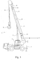
- FIG. 1 denotes a crane having, for example, a base part 2 (with drive for a driving operation), on which a rotary member 3 is arranged.
- a pivotable boom 4 base boom
- boom elements 5, 6 also only an additional boom element or more than two boom elements
- a hydraulic cylinder 7 is shown by way of example.
- a rope 8 (crane rope) runs over the tip of the boom element 6 to a hook 9 arranged at the end.
- the basic part 2 is represented by a length angle sensor 10, the structure of which is also known per se.
- This length angle sensor 10 is on the one hand suitable and adapted to detect the angle of the boom 4 with respect to the rotary part 3 and the base part 2 (not shown here).
- an output signal of the Conswinkelgebers 10 is designated, which is transmitted to a control device, not shown here.
- a cable 12 is present between the length angle sensor 10 and here the tip of the boom element 6.
- This cable 12 is rolled up in fully retracted boom elements 5, 6 in the Constantgeber 10 and can during extension of the boom elements 5, 6 of a Cable drum are rolled out in the length encoder 10. This process is detected in a conventional manner by theInternwinkelgeber 10, so that the output signal 11 not only transmits the angle of attack of the boom 4 to the control device, but also the respectively set length of the boom 4 with its boom elements 5, the sixth
- the cable 12 is associated with a force sensor 13, wherein this force sensor 13 in the embodiment according to FIG. 1 is located in the course of the cable 12 and in the end region of the boom element 6 (ie, in the direction of the boom tip) is arranged.
- this is only one embodiment of a force sensor 13 and its arrangement, wherein other locations in the course of the cable 12 are conceivable.
- the force sensor 13 according to FIG. 1 When the force acting on the cable 12 in its axial direction is detected directly, such force sensors also come into consideration, which detect the force acting on the cable 12 indirectly (for example, inductively).
- two identical or different force sensors may be present under safety-relevant aspects.
- the cable 12 is either designed in a conventional manner as a steel cable, so that it is necessary in this case, the force acting on the cable 12 at the cantilever tip force by suitable means (see FIG. 2 ) transferred to. If the cable 12 is designed as a data cable, the force sensor 13 can be connected to the data cable in a simple manner and its signals are transmitted in the direction of the rotary member 3, so that in this case the output signal 11 also contains the force acting on the cable 12.
- FIG. 2 shows a basic structure of a length sensor, in particular theJnwinkelgebers 10. It is a housing 14 is provided, in which all the required components of the length sensor are arranged. This is at least a drum 15 on or from which the cable 12 is wound up or down to determine the length.
- an electrically controllable motor 16 is housed, which replaces the previously known mechanical restoring system based on spring force.
- the housing 14 is suitably arranged and fixed to the boom 4.
- the length sensor is connected to a not shown Connected control device to which the output signal 11 are transmitted.
- the length sensor can be supplied with energy for the operation of the motor 16 from outside, in particular from the control device, and / or can have its own energy supply.
- FIG. 3 shows two principal courses of force in the cable 12, which can be adjusted by the appropriate setting or the control of the motor 16 over the course of the minimum (retracted) and maximum (fully extended) length of the telescopic boom 4 to 6. Even linear or nearly linear force curves can be adjusted.
Description
Die Erfindung betrifft einen Längengeber, ein Verfahren zum Betreiben eines Längengebers sowie einen Kran, bei dem solcher Längengeber angewandt wird, gemäß den Merkmalen der jeweiligen Oberbegriffe der unabhängigen Patentansprüche.The invention relates to a length sensor, a method for operating a length sensor and a crane, in which such length transmitter is applied, according to the features of the respective preambles of the independent claims.
Entwicklung von Sensorkomponenten mit integrierter Sicherheitselektronik für moderne mobile Maschinen wie Krane oder Bagger nach industriellen Sicherheitsstandards EN 61326 und IEC 61508.Development of sensor components with integrated safety electronics for modern mobile machines such as cranes or excavators according to industrial safety standards EN 61326 and IEC 61508.
Zum stabilen Betrieb eines Kranes sind u.a. Informationen von zahlreichen Sensoren notwendig. Mehrere Längen, unterschiedliche Winkel, Drücke und Kräfte werden gemessen und in einem übergreifenden mathematischen Modell verrechnet. Anschließend wird dieses Modell auf Instabilitäten und Sicherheitsabstände untersucht und entsprechende Empfehlungen, Vorschläge oder unmittelbare Reaktionen werden veranlasst und überwacht.For stable operation of a crane u.a. Information from numerous sensors necessary. Several lengths, different angles, pressures and forces are measured and calculated in a comprehensive mathematical model. Subsequently, this model is examined for instabilities and safety margins and appropriate recommendations, suggestions or immediate reactions are initiated and monitored.
Aus der
Der Erfindung liegt die Aufgabe zugrunde, ein Verfahren zum Betreiben eines Längengebers sowie seine Anwendung bei einem Kran bereitzustellen, welche gegenüber rein mechanischen Federsystemen zur Erzeugung einer Rückstellkraft des Rückstellsystemes verbessert sind.The invention has for its object to provide a method for operating a length sensor and its application in a crane, which are improved over purely mechanical spring systems for generating a restoring force of the return system.
Diese Aufgabe ist durch die Merkmale der unabhängigen Patentansprüche gelöst.This object is solved by the features of the independent claims.
Hinsichtlich des Längengebers, der nicht Teil der Erfindung ist, insbesondere des Längenwinkelgebers, ist vorgesehen, dass das Rückstellsystem einen steuerbaren elektrischen Motor aufweist. Während bei einem rein mechanisch wirkenden Rückstellsystem mit einer Feder zur Erzeugung der Rückstellungskraft vorgesehen ist, wird gemäß der Erfindung diese Kraft durch einen steuerbaren elektrischen Motor aufgebracht. Dadurch lässt sich in gezielter Weise die Rückstellkraft durch entsprechende Ansteuerung mittels einer Steuereinheit gezielt beeinflussen. So ist es aufgrund der Ansteuerung des elektrischen Motors möglich, dass zum Beispiel das Kabel immer mit einer konstanten, vorzugsweise mit einer nahezu konstanten Kraft auf die Trommel aufgewickelt bzw. von dieser abgewickelt wird, wenn bei einem Kran der Teleskopausleger ausgefahren bzw. eingefahren wird. Aufgrund dieser nahezu konstanten Kraft, die auf das Kabel wirkt, egal wie weit dieses auf die Trommel aufgewickelt oder von der Trommel abgewickelt ist, lässt sich der Verschleiß über die Betriebsdauer deutlich verringern. Der elektrische Motor wird dabei so angesteuert, dass er zum Beispiel beim Aufwickeln auf die Trommel als Antriebsmotor wirkt, wohingegen er beim Abwickeln des Kabels von der Trommel als Generator wirkt. Selbstverständlich kann er auch beim Abwickeln des Kabels von der Trommel als Generator wirken.With regard to the length transmitter, which is not part of the invention, in particular the Längenwinkelgebers, it is provided that the reset system has a controllable electric motor. While it is provided in a purely mechanically acting return system with a spring for generating the restoring force, according to the invention, this force is applied by a controllable electric motor. As a result, the restoring force can be selectively influenced by appropriate control by means of a control unit in a targeted manner. Thus, it is possible due to the control of the electric motor that, for example, the cable is always wound with a constant, preferably with a nearly constant force on the drum or unwound from this, if the telescopic boom is extended or retracted in a crane. Because of this nearly constant force acting on the cable, no matter how far this is wound on the drum or unwound from the drum, wear over the service life can be significantly reduced. The electric motor is driven so that it acts as a drive motor, for example when winding on the drum, whereas it acts as a generator when unwinding the cable from the drum. Of course, it can also act as a generator when unwinding the cable from the drum.
Üblicherweise sind solche Längengeber kompakte Baueinheiten, deren Bauelemente innerhalb eines Gehäuses untergebracht sind. Daher ist bei dem erfindungsgemäßen Längengeber entweder der Motor mit seiner Antriebsachse direkt auf der gleichen Achse wie die Trommel angeordnet oder der Motor ist indirekt über ein Getriebe mit der Trommel verbunden. Je nach Bauweise, Leistung und dergleichen des Motors bietet es sich an, diesen direkt oder indirekt über ein Getriebe mit der Trommel zu verbinden. Die direkte Verbindung des Motors mit der Trommel hat den Vorteil einer besonders kompakten Bauweise, sodass dadurch auch das gesamte Gehäuse des Längengebers kompakt bauend aufgebaut werden kann. Die indirekte Verbindung des Motors über ein Getriebe mit der Trommel hat den Vorteil, dass dadurch eine wesentlich feinfühligere Steuerung des Motors und damit der Einstellung der Kraft, die auf das Kabel wirkt, vorgenommen werden kann. Außerdem kann in beiden Fällen (direkte Anordnung der Achse des Motors auf der Achse der Trommel oder indirekte Verbindung) der Motor sicherstellen, dass beim Aufwickeln des Kabels auf der Trommel die notwendige Kraft zur Verfügung steht, um das Kabel auf die Trommel aufzuwickeln.Usually, such length encoders are compact units whose components are accommodated within a housing. Therefore, in the inventive encoder either the motor is arranged with its drive axle directly on the same axis as the drum or the motor is indirectly connected via a gear to the drum. Depending on the design, performance and the like of the engine, it makes sense to connect these directly or indirectly via a gearbox with the drum. The direct connection of the motor with the drum has the advantage of a particularly compact design, so that thereby the entire housing of the length encoder can be constructed compactly compact. The indirect connection of the engine via a gearbox with the drum has the advantage that this allows a much finer control of the motor and thus the adjustment of the force acting on the cable, can be made. In addition, in both cases (direct placement of the axis of the motor on the axis of the drum or indirect connection) the motor can ensure that when winding the cable on the drum the necessary force is available to wind the cable on the drum.
Der Längengeber weist eine eigene Stromversorgung auf. Üblicherweise wird der Motor, genauso wie die Steuereinheit zu seiner Ansteuerung, über eine externe Stromversorgung, zum Beispiel eines Kranes oder dergleichen, versorgt. Fällt jedoch diese Stromversorgung aus, kann die eigene Stromversorgung des Längengebers eingesetzt werden um zumindest den Motor, gegebenenfalls aber auch die Steuereinheit zu betreiben. Dies ist unter Sicherheitsaspekten, gerade bei Kranen, besonders wichtig.
Weiterhin ist zur Lösung der Aufgabe ein Verfahren zum Betreiben eines Längengebers vorgesehen, wobei das Rückstellsystem den schon beschriebenen steuerbaren elektrischen Motor aufweist und der Motor derart angesteuert wird, dass sich ein vorgebbarer Kraftverlauf des Kabels ergibt, wenn dieses von der Trommel abgewickelt und/oder auf die Trommel aufgewickelt wird. Durch entsprechende Ansteuerung des Motors wird damit sichergestellt, dass das Kabel, mit dem zum Beispiel die Länge eines Teleskopauslegers eines Kranes bestimmt wird, wenn dieser ein- bzw. ausgefahren wird, immer die gleiche mechanische Spannung aufweist, um damit möglichst genau die Länge des Teleskopauslegers zu detektieren.The length transmitter has its own power supply. Usually, the motor, as well as the control unit for its control, via an external power supply, for example a crane or the like supplied. However, if this power fails, the own power supply of the length encoder can be used to operate at least the engine, but possibly also the control unit. This is particularly important in terms of safety, especially for cranes.
Furthermore, a method for operating a length sensor is provided to achieve the object, wherein the reset system has the already described controllable electric motor and the motor is driven such that there is a predeterminable force curve of the cable when it unwound from the drum and / or on the drum is wound up. By appropriate control of the motor is thus ensured that the cable, for example, with the length of a telescopic boom of a crane is determined, if this is retracted or extended, always having the same mechanical stress in order to detect as accurately as possible the length of the telescopic boom.
In Weiterbildung der Erfindung ist hierzu vorgesehen, dass der Motor derart angesteuert wird, dass sich ein nahezu konstanter Kraftverlauf des Kabels ergibt, wenn dieses von der Trommel abgewickelt und/oder auf die Trommel aufgewickelt wird. Durch diesen konstanten, insbesondere nahezu konstanten Kraftverlauf des Kabels wird sichergestellt, dass dieses immer zwischen den beiden Endpunkten, zwischen denen sich der Teleskopausleger bewegen kann, die gleiche mechanische Spannung innerhalb des Kabels eingestellt wird. Dies führt insbesondere in vorteilhafter Weise dazu, dass das Kabel, welches üblicherweise in etwa parallel zu dem Teleskopausleger angeordnet ist, nicht oder nicht nennenswert durchhängt. Um bei größeren Längen des Teleskopauslegers eine Längenungenauigkeit durch das Durchhängen des Kabels zu kompensieren, kann daran gedacht werden, dass der Motor derart angesteuert wird, dass mit zunehmender Länge, das heißt weiter ausgefahrenem Teleskopausleger, die Kraft auf das Kabel durch entsprechende Ansteuerung des Motors erhöht wird. Dadurch spannt sich das Kabel in seinem Verlauf und ein Durchhängen wird vermieden. Die entsprechende Ansteuerung des Motors kann von einer Steuereinheit vorgenommen und auch berücksichtigt werden, wenn die Länge des abgewickelten Kabels und damit die Länge des ausgefahrenen Teleskopauslegers bestimmt wird.In a further development of the invention, provision is made for the motor to be controlled in such a way that an almost constant force curve of the cable results when it is unwound from the drum and / or wound onto the drum. This constant, in particular almost constant force curve of the cable ensures that this is always set between the two end points, between which the telescopic boom can move, the same mechanical stress within the cable. This leads in particular advantageously to the fact that the cable, which is usually arranged approximately parallel to the telescopic boom, not or not appreciably sags. In order to compensate for length inaccuracies in the length of the telescopic boom by the sagging of the cable, it can be thought that the motor is controlled such that increases with increasing length, that is further extended telescopic boom, the force on the cable by appropriate control of the motor becomes. As a result, the cable stretches in its course and sagging is avoided. The corresponding control of the motor can be made by a control unit and also taken into account when the length of the unwound cable and thus the length of the extended telescopic boom is determined.
Gemäß der Erfindung wird mit einem Kraftsensor die auf das Kabel wirkende Kraft gemessen. Dies hat zum einen den Vorteil, dass aufgrund der Kraftmessung nicht nur der Motor entsprechend angesteuert werden kann, sondern auch bestimmt werden kann, ob das Kabel in seinem axialen Verlauf durchhängt oder nicht. Denn mit zunehmender Abwicklung des Kabels von der Trommel stellt sich ein Durchhängen des Kabels (welches wie schon erläutert nahezu parallel zum Teleskopausleger des Kranes angeordnet ist) ein, sodass mit zunehmen Ausfahren des Teleskopauslegers eine höhere Kraft eingestellt werden muss, um dieses Durchhängen zu vermeiden. Durch die Korrelation der gemessenen Kraft und der Ansteuerung des Motors kann somit sichergestellt werden, dass das Kabel in seinem axialen Verlauf nicht oder nicht nennenswert durchhängt. Zum anderen ist mit der Kraftmessung gewährleistet, dass Probleme beim Abwickeln und/oder Aufwickeln des Kabels auf die Trommel erkannt werden. Insbesondere können ein Kabelbruch oder ein Kabelstau dadurch sehr genau erfasst werden. Denn verringert sich die gemessene Kraft abrupt, kann damit detektiert werden, dass ein Kabelbruch vorliegt. Steigt jedoch die auf das Kabel wirkende Kraft über einen vorgebbaren Schwellwert an, ist davon auszugehen, dass es sich um einen Kabelstau handelt. Dies kann durch die Kraftmessung entsprechend detektiert und darauf reagiert werden, was wiederum unter Sicherheitsaspekten bei Betrieb von Kränen besonders wichtig ist.According to the invention, the force acting on the cable is measured with a force sensor. This has the advantage that due to the force measurement not only the motor can be controlled accordingly, but also can be determined whether the cable sags in its axial course or not. Because with increasing unwinding of the cable from the drum is a sagging of the cable (which, as already explained is arranged almost parallel to the telescopic boom of the crane), so that with increasing extension of the telescopic boom a higher force must be set to avoid sagging. Through the correlation of the measured force and the Control of the motor can thus be ensured that the cable does not sag or not significantly in its axial course. On the other hand, the force measurement ensures that problems when unwinding and / or winding the cable onto the drum are recognized. In particular, a cable break or a cable jam can thereby be detected very accurately. Because the measured force decreases abruptly, it can be detected that there is a cable break. If, however, the force acting on the cable exceeds a predefinable threshold, it can be assumed that the cable is jamming. This can be detected by the force measurement and responded to, which in turn is particularly important in safety aspects when operating cranes.
In Weiterbildung der Erfindung werden weitere Betriebsparameter zur Ansteuerung des Motors berücksichtigt. Bei diesen Betriebsparametern handelt es sich um solche Betriebsparameter der Einrichtung, mit der die Länge durch den Längengeber erfasst wird. Ein typisches Beispiel ist hierfür ein Kran mit einem teleskopierbaren Ausleger, wobei sich die Länge des Teleskopauslegers dadurch ändert, dass ein feststehendes Auslegerelement vorgesehen ist und hiervon ausgehend zumindest ein weiteres Teleskopelement ausgefahren bzw. eingefahren werden kann. Je nach Betriebsart des Kranes kann der Motor entsprechend angesteuert werden.In a further development of the invention further operating parameters for controlling the motor are taken into account. These operating parameters are those operating parameters of the device with which the length is detected by the length transmitter. A typical example of this is a crane with a telescopic boom, wherein the length of the telescopic boom changes in that a fixed boom element is provided and starting from this at least one further telescopic element can be extended or retracted. Depending on the operating mode of the crane, the motor can be controlled accordingly.
Wie vorstehend beschrieben, geht die Erfindung von einem Längengeber aus, der die Trommel aufweist, von der das Kabel aufgewickelt bzw. auf die das Kabel aufgewickelt werden kann, um daraus direkt die aufgewickelte bzw. abgewickelte Länge des Kabels zu bestimmen, wobei diese Länge ein Maß für ein weiteres Element, insbesondere den Teleskopausleger, ist. In der Praxis hat es sich jedoch bewährt, nicht nur die bisher rein mechanisch wirkenden Längengeber mit mechanisch wirkenden Rückstellsystemen alleine einzusetzen, sondern auch in diese einen Winkelgeber zu integrieren. Mit dem Winkelgeber wird der Winkel des Teleskopauslegers, über den er ausgehend von einem Basisteil ausgestellt ist, gemessen. Besonders vorteilhaft ist jedoch die Integration sowohl der Winkelmessung als auch des erfindungsgemäßen elektrisch wirkenden Rückstellsystemes in einem Längenwinkelgeber. Alle hierfür notwendigen Elemente, insbesondere der Winkelgeber selber, die Trommel, der Motor und weitere notwendige Elemente, sind in einem Gehäuse untergebracht, welches an geeigneter Stelle an dem Kran, insbesondere dessen Teleskopausleger, angeordnet werden kann.As described above, the invention is based on a length transmitter having the drum, from which the cable can be wound or wound on the cable to directly determine the wound or unwound length of the cable, this length a Measure of another element, in particular the telescopic boom, is. In practice, it has proven useful not only to use the previously purely mechanical-acting length sensor with mechanically acting reset systems alone, but also to integrate into this one angle encoder. The angle transmitter measures the angle of the telescopic boom over which it is exposed starting from a base part. However, the integration of both the angle measurement and the electrically acting reset system according to the invention in a length angle encoder is particularly advantageous. All necessary elements, especially the angle encoder itself, the drum, the engine and more necessary elements are housed in a housing which can be arranged at a suitable location on the crane, in particular its telescopic boom.
Die Erfindung realisiert also eine intelligente Motorbremse für einen Längenwinkelgeber (LWG) als Ersatzlösung für ein mechanisches Federsystem. Denn wie schon vorstehend erwähnt wurden in den bisherigen LWG Sensoren rein mechanische Federsysteme zur Erzeugung einer Rückstellkraft eingesetzt. Solch ein typisches Rückstellsystem soll einen annährend konstanten Kraftverlauf garantieren und sich stabil sowohl bezüglich Umwelteinflüsse als auch gegenüber Sicherheitsanforderungen verhalten.The invention thus realizes an intelligent motor brake for a length angle sensor (LWG) as a replacement solution for a mechanical spring system. As already mentioned above, purely mechanical spring systems were used to generate a restoring force in the previous LWG sensors. Such a typical reset system is intended to guarantee an approximately constant force curve and to behave stably with respect to both environmental influences and safety requirements.
Gesucht wird eine elektrische, parametrierbare Lösung, die flexibel auf sich verändernde Anforderungen seitens der Applikation reagiert und sowohl zu Kosten als auch zu Gewichtsreduzierung beiträgt. In diesem Bereich kann es auch mehrere Arbeiten geben, u.a. in Richtung Konzepterstellung (Stichwort Simulationsmodelle), Lösungsentwurf sowie Realisierung mit anschließender Evaluierung.What is needed is an electrical, parameterizable solution that reacts flexibly to changing requirements of the application and contributes to both cost and weight reduction. There may also be several works in this area, i.a. in the direction of concept development (keyword simulation models), solution design as well as realization with subsequent evaluation.
Beschreibung der Idee:
- Nachbildung der Kennlinie "Kraftverlauf-Federsystem" mit Hilfe eines "intelligenten" elektrischen Motors
- "Erkennung" der Kranzustände (vorwärts, rückwärts, Halt, Aus, etc.) und Definition entsprechender Profile für die Bremse (langsam, schnell, testend, haltend, etc.)
- Erkennung von Kabellängung durch Einfahren in einen definierten Punkt und gleichzeitiger Längenmessung (evtl. als separate Idee)
- Sicherheitsaspekte wie Erkennung und Gegenwirkung beim Kabelbruch oder Kabelstau ("Impuls-Test")
- Integration eines Akku für den Fall "Spannung weg" (Überbrückung von ca. 3 bis 5 Minuten)
- Replica of the characteristic "force curve spring system" with the help of a "intelligent" electric motor
- "Detection" of crane conditions (forward, backward, stop, off, etc.) and definition of appropriate profiles for the brake (slow, fast, testing, holding, etc.)
- Detection of cable elongation by entering a defined point and simultaneous length measurement (possibly as a separate idea)
- Safety aspects such as cable break detection or counteraction or cable jamming ("Pulse Test")
- Integration of a battery for the case "voltage away" (bridging of approx. 3 to 5 minutes)
Intelligente Motorbremse für einen Längenwinkelgeber (LWG) eines Arbeitsfahrzeuges, insbesondere eines Kranes, als Ersatzlösung für ein mechanisches Federsystem, wobei eine elektrische, parametrierbare Lösung flexibel auf sich verändernde Anforderungen seitens der Applikation reagiert und sowohl zu einer Kosten- als auch zu einer Gewichtsreduzierung beiträgt.Intelligent motor brake for a longitude encoder (LWG) of a work vehicle, in particular a crane, as a replacement solution for a mechanical spring system, with an electrical, configurable solution responding flexibly to changing requirements of the application and contributes to both a cost and a weight reduction.
Ein Ausführungsbeispiel der Erfindung ist im Folgenden beschrieben und anhand der
In
Dem Kabel 12 ist ein Kraftsensor 13 zugeordnet, wobei sich dieser Kraftsensor 13 in dem Ausführungsbeispiel gemäß
- 1. Kran1. crane
- 2. Basisteil2nd base part
- 3. Drehteil3. Turned part
- 4. Ausleger4. boom
- 5. Auslegerelemente5. Boom elements
- 6. Auslegerelemente6. Boom elements
- 7. Hydraulikzylinder7. Hydraulic cylinder
- 8. Seil8. Rope
- 9. Haken9. Hook
- 10. Längenwinkelgeber10. Longitudinal encoder
- 11. Ausgangssignal11. Output signal
- 12. Kabel12. Cable
- 13. Kraftsensor13. Force sensor
- 14. Gehäuse14. Housing
- 15. Trommel15th drum
- 16. Elektrisch ansteuerbarer Motor16. Electrically controllable motor
Claims (4)
- Method for operating a length sensor, in particular a length/angle sensor (10) of a crane (1), with a resetting system, having a drum and a cable which is wound onto this drum and can be unwound from this drum in order to detect a length, wherein the resetting system has a controllable electric motor, and the motor is actuated in such a way that a predefinable force profile of the cable is obtained when the latter is unwound from the drum and/or wound onto the drum, characterized in that the force acting on the cable is measured with a force sensor.
- Method for operating a length sensor according to Claim 1, characterized in that the motor is actuated in such a way that a virtually constant force profile of the cable is obtained when the latter is unwound from the drum and/or wound onto the drum.
- Method for operating a length sensor according to Claim 1 or 2, characterized in that the revolutions of the drum are measured with a rotational speed sensor, wherein the wound-on and/or unwound length of the cable is determined therefrom.
- Method for operating a length sensor according to Claim 1, 2 or 3, characterized in that further operating parameters relating to the actuation of the motor are taken into account.
Applications Claiming Priority (2)
| Application Number | Priority Date | Filing Date | Title |
|---|---|---|---|
| DE102013216246 | 2013-08-15 | ||
| PCT/EP2014/067442 WO2015022405A1 (en) | 2013-08-15 | 2014-08-14 | Intelligent motor brake for a length/angle sensor of a crane |
Publications (2)
| Publication Number | Publication Date |
|---|---|
| EP3033294A1 EP3033294A1 (en) | 2016-06-22 |
| EP3033294B1 true EP3033294B1 (en) | 2019-06-05 |
Family
ID=51352511
Family Applications (1)
| Application Number | Title | Priority Date | Filing Date |
|---|---|---|---|
| EP14750754.5A Active EP3033294B1 (en) | 2013-08-15 | 2014-08-14 | Intelligent motor brake for a length/angle sensor of a crane |
Country Status (9)
| Country | Link |
|---|---|
| US (1) | US20160145081A1 (en) |
| EP (1) | EP3033294B1 (en) |
| JP (1) | JP2016528128A (en) |
| CN (1) | CN105452148A (en) |
| BR (1) | BR112016001784A2 (en) |
| CA (1) | CA2921626A1 (en) |
| DE (1) | DE102014216206A1 (en) |
| RU (1) | RU2016107193A (en) |
| WO (1) | WO2015022405A1 (en) |
Cited By (1)
| Publication number | Priority date | Publication date | Assignee | Title |
|---|---|---|---|---|
| WO2023078509A1 (en) * | 2021-11-08 | 2023-05-11 | Fernsteuergeräte Kurt Oelsch GmbH | Draw-wire sensor with an electric drive |
Families Citing this family (9)
| Publication number | Priority date | Publication date | Assignee | Title |
|---|---|---|---|---|
| US20190173310A1 (en) * | 2015-03-16 | 2019-06-06 | Saud AlZamil | Electromechanical set replacing a Diesel Engine |
| ITUA20161449A1 (en) * | 2016-03-08 | 2017-09-08 | Fassi Gru S P A | Crane comprising an extendable arm and a device for measuring the extension of this extensible arm |
| CN108083188B (en) * | 2017-12-14 | 2023-07-28 | 江苏徐工国重实验室科技有限公司 | Boom control device and method, aerial work platform and computer readable storage medium |
| JP6665874B2 (en) | 2018-02-16 | 2020-03-13 | 株式会社タダノ | crane |
| CN109186530B (en) * | 2018-09-10 | 2020-05-01 | 中国一冶集团有限公司 | Method for monitoring bending degree of suspension arm |
| WO2020226739A1 (en) * | 2019-05-07 | 2020-11-12 | Tulsa Winch, Inc. | Load moment indicator |
| CN110626959A (en) * | 2019-09-17 | 2019-12-31 | 夏枫 | Engineering machine tool structure hangs commentaries on classics device |
| CN113548542B (en) * | 2021-07-12 | 2023-03-14 | 三一海洋重工有限公司 | Cable winding and unwinding control method, device and system for hoisting equipment |
| CN114314205A (en) * | 2021-12-22 | 2022-04-12 | 武汉理工大学 | Ship shore power cable lifting device and method based on PID |
Family Cites Families (9)
| Publication number | Priority date | Publication date | Assignee | Title |
|---|---|---|---|---|
| GB1176943A (en) * | 1966-05-25 | 1970-01-07 | H & S Hydraulics Ltd | An Improvement in or relating to Safety Devices for Cranes |
| US3812589A (en) * | 1972-05-25 | 1974-05-28 | Dillon W & Co Inc | Boom length indicator |
| US4003482A (en) * | 1972-11-27 | 1977-01-18 | Societe Anonyme Dite: Potain Poclain Materiel | Safety device for a crane |
| JPS5413973Y2 (en) * | 1973-01-24 | 1979-06-12 | ||
| US3833130A (en) * | 1973-04-20 | 1974-09-03 | Krupp Gmbh | Safety device for a top boom pivotally mounted on a crane boom |
| JPS51126164A (en) * | 1975-04-25 | 1976-11-04 | Nippon Globe Kk | Device for measuring expansion multistage boom |
| JPH074482U (en) * | 1993-06-28 | 1995-01-24 | 東日本旅客鉄道株式会社 | Crane-mounted attitude detection alarm device |
| JP5543699B2 (en) * | 2008-05-30 | 2014-07-09 | 古河ユニック株式会社 | Boom length detection device |
| DE102012221909A1 (en) | 2012-11-29 | 2014-06-05 | Hirschmann Automation And Control Gmbh | Cable break diagnostics for a crane |
-
2014
- 2014-08-14 EP EP14750754.5A patent/EP3033294B1/en active Active
- 2014-08-14 DE DE102014216206.8A patent/DE102014216206A1/en not_active Withdrawn
- 2014-08-14 US US14/902,936 patent/US20160145081A1/en not_active Abandoned
- 2014-08-14 WO PCT/EP2014/067442 patent/WO2015022405A1/en active Application Filing
- 2014-08-14 CA CA2921626A patent/CA2921626A1/en not_active Abandoned
- 2014-08-14 RU RU2016107193A patent/RU2016107193A/en not_active Application Discontinuation
- 2014-08-14 JP JP2016533924A patent/JP2016528128A/en active Pending
- 2014-08-14 BR BR112016001784A patent/BR112016001784A2/en not_active Application Discontinuation
- 2014-08-14 CN CN201480045210.0A patent/CN105452148A/en active Pending
Non-Patent Citations (1)
| Title |
|---|
| None * |
Cited By (1)
| Publication number | Priority date | Publication date | Assignee | Title |
|---|---|---|---|---|
| WO2023078509A1 (en) * | 2021-11-08 | 2023-05-11 | Fernsteuergeräte Kurt Oelsch GmbH | Draw-wire sensor with an electric drive |
Also Published As
| Publication number | Publication date |
|---|---|
| CN105452148A (en) | 2016-03-30 |
| EP3033294A1 (en) | 2016-06-22 |
| JP2016528128A (en) | 2016-09-15 |
| BR112016001784A2 (en) | 2017-08-01 |
| CA2921626A1 (en) | 2015-02-19 |
| US20160145081A1 (en) | 2016-05-26 |
| WO2015022405A1 (en) | 2015-02-19 |
| DE102014216206A1 (en) | 2015-02-19 |
| RU2016107193A (en) | 2017-09-20 |
Similar Documents
| Publication | Publication Date | Title |
|---|---|---|
| EP3033294B1 (en) | Intelligent motor brake for a length/angle sensor of a crane | |
| EP3126181B1 (en) | Method for checking a connection between a low-voltage supply system and a battery, and motor vehicle | |
| EP2159428B1 (en) | Piston-cylinder-unit | |
| DE102010020016B4 (en) | Crane and method of erecting the crane | |
| EP2871149B1 (en) | Drive for a slide of a locking system of a telescopic system of a crane arm | |
| DE102013200602A1 (en) | Power tool with improved usability | |
| DE102014202276A1 (en) | Power supply voltage monitoring circuit, sensor circuit for a vehicle and power steering device | |
| WO2014082792A1 (en) | Cable breakage diagnosis in a crane | |
| DE102012215391A1 (en) | Load measurement on the load receiver of hoists | |
| DE102009041340A1 (en) | Scalping device for use in scalping machine for machine processing of e.g. rod shaped designed semi-finished product, has component engaging gear that rotates with scalping head, by implementing component movement regarding to head | |
| DE102015004086A1 (en) | Device and method for moving an aircraft, in particular a helicopter, aboard a ship | |
| DE102014213620A1 (en) | Method for determining a position of a linearly moving actuator in an actuator system, in particular a clutch actuation system of a motor vehicle and an actuator system | |
| EP3594027B1 (en) | Control module and method of controlling a trailer coupling | |
| WO2014117961A1 (en) | Method and device for determining the offset of an electric window lift system | |
| EP2962980A1 (en) | Towing winch for air sports devices, and method for operating such a towing winch | |
| DE102018215296A1 (en) | Method and device for reliable electric power steering | |
| EP2019346B1 (en) | Marquee motor control | |
| EP2852548A1 (en) | Measuring the jib length of a crane using transit time measurement | |
| EP1181232B1 (en) | Method for synchronously retracting and extending telescopic lengths of a crane jib | |
| DE102020107032A1 (en) | Hydraulic valve module for safe shutdown in the event of failure of an external power supply and method for operating a hydraulic valve | |
| EP3723238A1 (en) | Electrical installation | |
| DE102008056508B3 (en) | Universal optoelectronic closure edge safety device for use with control of e.g. gate, for cabled or wireless operation, has internal measuring inputs for adjusting operation modes of transmitter control unit and/or receiver analysis unit | |
| EP4016206B1 (en) | Sensor arrangement, control device, automation system and method for transmitting signals according to two communication standards | |
| DE10223449A1 (en) | Telescopic system e.g. for crane boom, has recognition device with measurement value receiver fitted to telescoping device in region of coupling unit | |
| EP3762324B1 (en) | Method for controlling and in particular monitoring an actuator, in particular of a winch, a hoist or a crane, and system for carrying out such a method |
Legal Events
| Date | Code | Title | Description |
|---|---|---|---|
| PUAI | Public reference made under article 153(3) epc to a published international application that has entered the european phase |
Free format text: ORIGINAL CODE: 0009012 |
|
| 17P | Request for examination filed |
Effective date: 20160106 |
|
| AK | Designated contracting states |
Kind code of ref document: A1 Designated state(s): AL AT BE BG CH CY CZ DE DK EE ES FI FR GB GR HR HU IE IS IT LI LT LU LV MC MK MT NL NO PL PT RO RS SE SI SK SM TR |
|
| AX | Request for extension of the european patent |
Extension state: BA ME |
|
| STAA | Information on the status of an ep patent application or granted ep patent |
Free format text: STATUS: REQUEST FOR EXAMINATION WAS MADE |
|
| DAX | Request for extension of the european patent (deleted) | ||
| GRAP | Despatch of communication of intention to grant a patent |
Free format text: ORIGINAL CODE: EPIDOSNIGR1 |
|
| STAA | Information on the status of an ep patent application or granted ep patent |
Free format text: STATUS: GRANT OF PATENT IS INTENDED |
|
| RIC1 | Information provided on ipc code assigned before grant |
Ipc: B66C 23/70 20060101ALI20181012BHEP Ipc: B65H 75/44 20060101ALI20181012BHEP Ipc: B66C 13/22 20060101ALI20181012BHEP Ipc: G01B 7/02 20060101ALI20181012BHEP Ipc: B66C 23/90 20060101AFI20181012BHEP |
|
| INTG | Intention to grant announced |
Effective date: 20181107 |
|
| GRAS | Grant fee paid |
Free format text: ORIGINAL CODE: EPIDOSNIGR3 |
|
| GRAA | (expected) grant |
Free format text: ORIGINAL CODE: 0009210 |
|
| STAA | Information on the status of an ep patent application or granted ep patent |
Free format text: STATUS: THE PATENT HAS BEEN GRANTED |
|
| RAP1 | Party data changed (applicant data changed or rights of an application transferred) |
Owner name: WIKA MOBILE CONTROL GMBH & CO. KG |
|
| AK | Designated contracting states |
Kind code of ref document: B1 Designated state(s): AL AT BE BG CH CY CZ DE DK EE ES FI FR GB GR HR HU IE IS IT LI LT LU LV MC MK MT NL NO PL PT RO RS SE SI SK SM TR |
|
| REG | Reference to a national code |
Ref country code: GB Ref legal event code: FG4D Free format text: NOT ENGLISH |
|
| REG | Reference to a national code |
Ref country code: CH Ref legal event code: EP |
|
| REG | Reference to a national code |
Ref country code: AT Ref legal event code: REF Ref document number: 1139797 Country of ref document: AT Kind code of ref document: T Effective date: 20190615 |
|
| REG | Reference to a national code |
Ref country code: IE Ref legal event code: FG4D Free format text: LANGUAGE OF EP DOCUMENT: GERMAN |
|
| REG | Reference to a national code |
Ref country code: DE Ref legal event code: R096 Ref document number: 502014011869 Country of ref document: DE |
|
| REG | Reference to a national code |
Ref country code: NL Ref legal event code: MP Effective date: 20190605 |
|
| REG | Reference to a national code |
Ref country code: LT Ref legal event code: MG4D |
|
| PG25 | Lapsed in a contracting state [announced via postgrant information from national office to epo] |
Ref country code: ES Free format text: LAPSE BECAUSE OF FAILURE TO SUBMIT A TRANSLATION OF THE DESCRIPTION OR TO PAY THE FEE WITHIN THE PRESCRIBED TIME-LIMIT Effective date: 20190605 Ref country code: SE Free format text: LAPSE BECAUSE OF FAILURE TO SUBMIT A TRANSLATION OF THE DESCRIPTION OR TO PAY THE FEE WITHIN THE PRESCRIBED TIME-LIMIT Effective date: 20190605 Ref country code: AL Free format text: LAPSE BECAUSE OF FAILURE TO SUBMIT A TRANSLATION OF THE DESCRIPTION OR TO PAY THE FEE WITHIN THE PRESCRIBED TIME-LIMIT Effective date: 20190605 Ref country code: HR Free format text: LAPSE BECAUSE OF FAILURE TO SUBMIT A TRANSLATION OF THE DESCRIPTION OR TO PAY THE FEE WITHIN THE PRESCRIBED TIME-LIMIT Effective date: 20190605 Ref country code: LT Free format text: LAPSE BECAUSE OF FAILURE TO SUBMIT A TRANSLATION OF THE DESCRIPTION OR TO PAY THE FEE WITHIN THE PRESCRIBED TIME-LIMIT Effective date: 20190605 Ref country code: FI Free format text: LAPSE BECAUSE OF FAILURE TO SUBMIT A TRANSLATION OF THE DESCRIPTION OR TO PAY THE FEE WITHIN THE PRESCRIBED TIME-LIMIT Effective date: 20190605 Ref country code: NO Free format text: LAPSE BECAUSE OF FAILURE TO SUBMIT A TRANSLATION OF THE DESCRIPTION OR TO PAY THE FEE WITHIN THE PRESCRIBED TIME-LIMIT Effective date: 20190905 |
|
| PG25 | Lapsed in a contracting state [announced via postgrant information from national office to epo] |
Ref country code: RS Free format text: LAPSE BECAUSE OF FAILURE TO SUBMIT A TRANSLATION OF THE DESCRIPTION OR TO PAY THE FEE WITHIN THE PRESCRIBED TIME-LIMIT Effective date: 20190605 Ref country code: GR Free format text: LAPSE BECAUSE OF FAILURE TO SUBMIT A TRANSLATION OF THE DESCRIPTION OR TO PAY THE FEE WITHIN THE PRESCRIBED TIME-LIMIT Effective date: 20190906 Ref country code: LV Free format text: LAPSE BECAUSE OF FAILURE TO SUBMIT A TRANSLATION OF THE DESCRIPTION OR TO PAY THE FEE WITHIN THE PRESCRIBED TIME-LIMIT Effective date: 20190605 Ref country code: BG Free format text: LAPSE BECAUSE OF FAILURE TO SUBMIT A TRANSLATION OF THE DESCRIPTION OR TO PAY THE FEE WITHIN THE PRESCRIBED TIME-LIMIT Effective date: 20190905 |
|
| PG25 | Lapsed in a contracting state [announced via postgrant information from national office to epo] |
Ref country code: PT Free format text: LAPSE BECAUSE OF FAILURE TO SUBMIT A TRANSLATION OF THE DESCRIPTION OR TO PAY THE FEE WITHIN THE PRESCRIBED TIME-LIMIT Effective date: 20191007 Ref country code: SK Free format text: LAPSE BECAUSE OF FAILURE TO SUBMIT A TRANSLATION OF THE DESCRIPTION OR TO PAY THE FEE WITHIN THE PRESCRIBED TIME-LIMIT Effective date: 20190605 Ref country code: RO Free format text: LAPSE BECAUSE OF FAILURE TO SUBMIT A TRANSLATION OF THE DESCRIPTION OR TO PAY THE FEE WITHIN THE PRESCRIBED TIME-LIMIT Effective date: 20190605 Ref country code: EE Free format text: LAPSE BECAUSE OF FAILURE TO SUBMIT A TRANSLATION OF THE DESCRIPTION OR TO PAY THE FEE WITHIN THE PRESCRIBED TIME-LIMIT Effective date: 20190605 Ref country code: CZ Free format text: LAPSE BECAUSE OF FAILURE TO SUBMIT A TRANSLATION OF THE DESCRIPTION OR TO PAY THE FEE WITHIN THE PRESCRIBED TIME-LIMIT Effective date: 20190605 Ref country code: NL Free format text: LAPSE BECAUSE OF FAILURE TO SUBMIT A TRANSLATION OF THE DESCRIPTION OR TO PAY THE FEE WITHIN THE PRESCRIBED TIME-LIMIT Effective date: 20190605 |
|
| REG | Reference to a national code |
Ref country code: DE Ref legal event code: R082 Ref document number: 502014011869 Country of ref document: DE Representative=s name: RWZH RECHTSANWAELTE WACHINGER ZOEBISCH PARTNER, DE |
|
| REG | Reference to a national code |
Ref country code: DE Ref legal event code: R082 Ref document number: 502014011869 Country of ref document: DE Representative=s name: RWZH RECHTSANWAELTE WACHINGER ZOEBISCH PARTNER, DE |
|
| PG25 | Lapsed in a contracting state [announced via postgrant information from national office to epo] |
Ref country code: SM Free format text: LAPSE BECAUSE OF FAILURE TO SUBMIT A TRANSLATION OF THE DESCRIPTION OR TO PAY THE FEE WITHIN THE PRESCRIBED TIME-LIMIT Effective date: 20190605 Ref country code: IT Free format text: LAPSE BECAUSE OF FAILURE TO SUBMIT A TRANSLATION OF THE DESCRIPTION OR TO PAY THE FEE WITHIN THE PRESCRIBED TIME-LIMIT Effective date: 20190605 Ref country code: IS Free format text: LAPSE BECAUSE OF FAILURE TO SUBMIT A TRANSLATION OF THE DESCRIPTION OR TO PAY THE FEE WITHIN THE PRESCRIBED TIME-LIMIT Effective date: 20191005 |
|
| REG | Reference to a national code |
Ref country code: DE Ref legal event code: R097 Ref document number: 502014011869 Country of ref document: DE |
|
| PG25 | Lapsed in a contracting state [announced via postgrant information from national office to epo] |
Ref country code: TR Free format text: LAPSE BECAUSE OF FAILURE TO SUBMIT A TRANSLATION OF THE DESCRIPTION OR TO PAY THE FEE WITHIN THE PRESCRIBED TIME-LIMIT Effective date: 20190605 |
|
| PLBE | No opposition filed within time limit |
Free format text: ORIGINAL CODE: 0009261 |
|
| STAA | Information on the status of an ep patent application or granted ep patent |
Free format text: STATUS: NO OPPOSITION FILED WITHIN TIME LIMIT |
|
| PG25 | Lapsed in a contracting state [announced via postgrant information from national office to epo] |
Ref country code: PL Free format text: LAPSE BECAUSE OF FAILURE TO SUBMIT A TRANSLATION OF THE DESCRIPTION OR TO PAY THE FEE WITHIN THE PRESCRIBED TIME-LIMIT Effective date: 20190605 Ref country code: DK Free format text: LAPSE BECAUSE OF FAILURE TO SUBMIT A TRANSLATION OF THE DESCRIPTION OR TO PAY THE FEE WITHIN THE PRESCRIBED TIME-LIMIT Effective date: 20190605 |
|
| 26N | No opposition filed |
Effective date: 20200306 |
|
| PG25 | Lapsed in a contracting state [announced via postgrant information from national office to epo] |
Ref country code: MC Free format text: LAPSE BECAUSE OF FAILURE TO SUBMIT A TRANSLATION OF THE DESCRIPTION OR TO PAY THE FEE WITHIN THE PRESCRIBED TIME-LIMIT Effective date: 20190605 Ref country code: CH Free format text: LAPSE BECAUSE OF NON-PAYMENT OF DUE FEES Effective date: 20190831 Ref country code: LI Free format text: LAPSE BECAUSE OF NON-PAYMENT OF DUE FEES Effective date: 20190831 Ref country code: SI Free format text: LAPSE BECAUSE OF FAILURE TO SUBMIT A TRANSLATION OF THE DESCRIPTION OR TO PAY THE FEE WITHIN THE PRESCRIBED TIME-LIMIT Effective date: 20190605 Ref country code: LU Free format text: LAPSE BECAUSE OF NON-PAYMENT OF DUE FEES Effective date: 20190814 |
|
| REG | Reference to a national code |
Ref country code: BE Ref legal event code: MM Effective date: 20190831 |
|
| PG25 | Lapsed in a contracting state [announced via postgrant information from national office to epo] |
Ref country code: FR Free format text: LAPSE BECAUSE OF NON-PAYMENT OF DUE FEES Effective date: 20190831 Ref country code: IE Free format text: LAPSE BECAUSE OF NON-PAYMENT OF DUE FEES Effective date: 20190814 |
|
| PG25 | Lapsed in a contracting state [announced via postgrant information from national office to epo] |
Ref country code: BE Free format text: LAPSE BECAUSE OF NON-PAYMENT OF DUE FEES Effective date: 20190831 |
|
| GBPC | Gb: european patent ceased through non-payment of renewal fee |
Effective date: 20190905 |
|
| REG | Reference to a national code |
Ref country code: AT Ref legal event code: MM01 Ref document number: 1139797 Country of ref document: AT Kind code of ref document: T Effective date: 20190814 |
|
| PG25 | Lapsed in a contracting state [announced via postgrant information from national office to epo] |
Ref country code: GB Free format text: LAPSE BECAUSE OF NON-PAYMENT OF DUE FEES Effective date: 20190905 |
|
| PG25 | Lapsed in a contracting state [announced via postgrant information from national office to epo] |
Ref country code: AT Free format text: LAPSE BECAUSE OF NON-PAYMENT OF DUE FEES Effective date: 20190814 |
|
| PG25 | Lapsed in a contracting state [announced via postgrant information from national office to epo] |
Ref country code: CY Free format text: LAPSE BECAUSE OF FAILURE TO SUBMIT A TRANSLATION OF THE DESCRIPTION OR TO PAY THE FEE WITHIN THE PRESCRIBED TIME-LIMIT Effective date: 20190605 |
|
| PG25 | Lapsed in a contracting state [announced via postgrant information from national office to epo] |
Ref country code: HU Free format text: LAPSE BECAUSE OF FAILURE TO SUBMIT A TRANSLATION OF THE DESCRIPTION OR TO PAY THE FEE WITHIN THE PRESCRIBED TIME-LIMIT; INVALID AB INITIO Effective date: 20140814 Ref country code: MT Free format text: LAPSE BECAUSE OF FAILURE TO SUBMIT A TRANSLATION OF THE DESCRIPTION OR TO PAY THE FEE WITHIN THE PRESCRIBED TIME-LIMIT Effective date: 20190605 |
|
| PG25 | Lapsed in a contracting state [announced via postgrant information from national office to epo] |
Ref country code: MK Free format text: LAPSE BECAUSE OF FAILURE TO SUBMIT A TRANSLATION OF THE DESCRIPTION OR TO PAY THE FEE WITHIN THE PRESCRIBED TIME-LIMIT Effective date: 20190605 |
|
| PGFP | Annual fee paid to national office [announced via postgrant information from national office to epo] |
Ref country code: DE Payment date: 20230822 Year of fee payment: 10 |