EP3032343A1 - Image forming apparatus - Google Patents
Image forming apparatus Download PDFInfo
- Publication number
- EP3032343A1 EP3032343A1 EP15198204.8A EP15198204A EP3032343A1 EP 3032343 A1 EP3032343 A1 EP 3032343A1 EP 15198204 A EP15198204 A EP 15198204A EP 3032343 A1 EP3032343 A1 EP 3032343A1
- Authority
- EP
- European Patent Office
- Prior art keywords
- support member
- cover member
- opening
- image forming
- shape
- Prior art date
- Legal status (The legal status is an assumption and is not a legal conclusion. Google has not performed a legal analysis and makes no representation as to the accuracy of the status listed.)
- Granted
Links
Images


Classifications
-
- G—PHYSICS
- G03—PHOTOGRAPHY; CINEMATOGRAPHY; ANALOGOUS TECHNIQUES USING WAVES OTHER THAN OPTICAL WAVES; ELECTROGRAPHY; HOLOGRAPHY
- G03G—ELECTROGRAPHY; ELECTROPHOTOGRAPHY; MAGNETOGRAPHY
- G03G21/00—Arrangements not provided for by groups G03G13/00 - G03G19/00, e.g. cleaning, elimination of residual charge
- G03G21/16—Mechanical means for facilitating the maintenance of the apparatus, e.g. modular arrangements
- G03G21/1604—Arrangement or disposition of the entire apparatus
- G03G21/1623—Means to access the interior of the apparatus
- G03G21/1638—Means to access the interior of the apparatus directed to paper handling or jam treatment
-
- G—PHYSICS
- G03—PHOTOGRAPHY; CINEMATOGRAPHY; ANALOGOUS TECHNIQUES USING WAVES OTHER THAN OPTICAL WAVES; ELECTROGRAPHY; HOLOGRAPHY
- G03G—ELECTROGRAPHY; ELECTROPHOTOGRAPHY; MAGNETOGRAPHY
- G03G21/00—Arrangements not provided for by groups G03G13/00 - G03G19/00, e.g. cleaning, elimination of residual charge
- G03G21/16—Mechanical means for facilitating the maintenance of the apparatus, e.g. modular arrangements
- G03G21/1604—Arrangement or disposition of the entire apparatus
- G03G21/1623—Means to access the interior of the apparatus
- G03G21/1633—Means to access the interior of the apparatus using doors or covers
-
- G—PHYSICS
- G03—PHOTOGRAPHY; CINEMATOGRAPHY; ANALOGOUS TECHNIQUES USING WAVES OTHER THAN OPTICAL WAVES; ELECTROGRAPHY; HOLOGRAPHY
- G03G—ELECTROGRAPHY; ELECTROPHOTOGRAPHY; MAGNETOGRAPHY
- G03G2215/00—Apparatus for electrophotographic processes
- G03G2215/00362—Apparatus for electrophotographic processes relating to the copy medium handling
- G03G2215/00535—Stable handling of copy medium
- G03G2215/00544—Openable part of feed path
-
- G—PHYSICS
- G03—PHOTOGRAPHY; CINEMATOGRAPHY; ANALOGOUS TECHNIQUES USING WAVES OTHER THAN OPTICAL WAVES; ELECTROGRAPHY; HOLOGRAPHY
- G03G—ELECTROGRAPHY; ELECTROPHOTOGRAPHY; MAGNETOGRAPHY
- G03G2221/00—Processes not provided for by group G03G2215/00, e.g. cleaning or residual charge elimination
- G03G2221/16—Mechanical means for facilitating the maintenance of the apparatus, e.g. modular arrangements and complete machine concepts
- G03G2221/1672—Paper handling
- G03G2221/1675—Paper handling jam treatment
-
- G—PHYSICS
- G03—PHOTOGRAPHY; CINEMATOGRAPHY; ANALOGOUS TECHNIQUES USING WAVES OTHER THAN OPTICAL WAVES; ELECTROGRAPHY; HOLOGRAPHY
- G03G—ELECTROGRAPHY; ELECTROPHOTOGRAPHY; MAGNETOGRAPHY
- G03G2221/00—Processes not provided for by group G03G2215/00, e.g. cleaning or residual charge elimination
- G03G2221/16—Mechanical means for facilitating the maintenance of the apparatus, e.g. modular arrangements and complete machine concepts
- G03G2221/1678—Frame structures
- G03G2221/169—Structural door designs
Definitions
- the cover member is pivotally supported to a lower edge portion of the aforementioned opening and rotates by employing the pivotally supported part as a fulcrum, thereby allowing the opening to be openable and closable.
- the aforementioned image forming apparatus is further provided with a flexible support member for restricting an opening angle of the cover member to a maximum opening angle at the time of opening of the cover member.
- the support member has one end portion fixed to the cover member by a screw and the like, and the other end portion mounted at the housing by a screw and the like.
- the aforementioned support member is provided at an intermediate portion thereof in a longitudinal direction with wavelike portions.
- the wavelike portion has a wave shape when viewed from a width direction perpendicular to the longitudinal direction of the support member and has elasticity in the longitudinal direction.
- the hooking surface 36a of the locking portion 36 of the one end side mounting portion 34a is formed to make surface contact with the hooked surfaces 51a of the pair of leg parts 51 of the U-shaped member 50 in the state of abutting the inner wall surface 20a of the cover member 20 (in the maximally opened state of the cover member 20).
Landscapes
- Physics & Mathematics (AREA)
- General Physics & Mathematics (AREA)
- Electrophotography Configuration And Component (AREA)
- Electrostatic Charge, Transfer And Separation In Electrography (AREA)
Abstract
Description
- The present invention relates to an image forming apparatus.
- Conventionally, there has been known an image forming apparatus in which a jam handling opening has been formed at one side of a housing having accommodated an image forming unit. The housing is provided therein with a paper conveyance path from a paper feeding unit to a paper discharge unit via the image forming unit, and the aforementioned opening is provided at a side wall part adjacent to the paper conveyance path. The opening is covered by a cover member so as to be openable and closable. When jam has occurred in the paper conveyance path, a user can open the cover member, thereby performing a removal work of a jammed paper in the paper conveyance path. The cover member is integrally mounted with a transfer roller, a resist roller, and a paper guide member.
- The cover member is pivotally supported to a lower edge portion of the aforementioned opening and rotates by employing the pivotally supported part as a fulcrum, thereby allowing the opening to be openable and closable. The aforementioned image forming apparatus is further provided with a flexible support member for restricting an opening angle of the cover member to a maximum opening angle at the time of opening of the cover member. The support member has one end portion fixed to the cover member by a screw and the like, and the other end portion mounted at the housing by a screw and the like.
- An image forming apparatus according to one aspect of the present disclosure includes a housing, a cover member, and a support member. The housing accommodates an image forming unit therein. The housing is formed at one side surface thereof with an opening. The cover member is configured to be pivotally supported to a lower edge portion of the opening and to be rotated to an outer side of the aforementioned housing from a closed state, in which the opening is closed, by employing a shaft as a fulcrum, thereby opening the opening. The support member includes a long belt-shaped member. The support member has one end portion mounted at the aforementioned housing and the other end portion mounted at the cover member. The support member restricts an opening angle of the cover member to a predetermined maximum opening angle.
- Furthermore, the aforementioned support member is provided at an intermediate portion thereof in a longitudinal direction with wavelike portions. The wavelike portion has a wave shape when viewed from a width direction perpendicular to the longitudinal direction of the support member and has elasticity in the longitudinal direction.
-
-
Fig. 1 is a schematic configuration diagram illustrating an image forming apparatus in an embodiment. -
Fig. 2 is a perspective view illustrating a cover member. -
Fig. 3 is a sectional view illustrating a closed state of a cover member. -
Fig. 4 is a sectional view illustrating an opened state of a cover member. -
Fig. 5 is an entire perspective view illustrating a state in which a support member has been unfolded in a straight line shape. -
Fig. 6 is an entire perspective view illustrating a state in which a support member has been curved in a U shape. -
Fig. 7 is a sectional view taken along line VII-VII ofFig. 3 . -
Fig. 8 is an enlarged perspective view of a part VIII ofFig. 5 . -
Fig. 9 is an enlarged view of a part IX ofFig. 3 . -
Fig. 10 is an enlarged view of a part X ofFig. 4 . -
Fig. 11 is a perspective view illustrating a holding member that holds the other end portion of a support member when viewed from the front side and the left side of an image forming apparatus. -
Fig. 12 is a view viewed in the arrow direction of XII ofFig. 11 . -
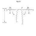
Fig. 13 is a schematic view illustrating a support member in a comparison example. - Hereinafter, an example of an embodiment will be described in detail on the basis of the drawings. It is noted that the technology of the present disclosure is not limited to the following embodiments.
-
Fig. 1 is a schematic configuration diagram illustrating an image forming apparatus 1 in an embodiment. In the following description, it is assumed that a front side and a rear side indicate a front side and a rear side (a front side and a back side in a direction perpendicular to the paper surface ofFig. 1 ) of the image forming apparatus 1, and a left side and a right side indicate a left side and a right side when the image forming apparatus 1 is viewed from the front side. - The aforementioned image forming apparatus 1 is a tandem type color printer and includes an
image forming unit 3 in a box-like housing 2. Theimage forming unit 3 is an element that transfers an image to a paper P and forms the image on the paper P on the basis of image data transmitted from an external device such as a computer subjected to network connection and the like. Below theimage forming unit 3, anexposure device 4 is arranged to irradiate laser light, and above theimage forming unit 3, atransfer belt 5 is arranged. Below theexposure device 4, apaper feeding unit 6 is arranged to store the paper P. Above the right side of thetransfer belt 5, afixing unit 8 is arranged to perform a fixing process on the image transferred to and formed on the paper P. At an upper portion of thehousing 2, apaper discharge unit 9 is arranged to discharge the paper P subjected to the fixing process in thefixing unit 8. In the image forming apparatus 1, a paper conveyance path T extending toward thepaper discharge unit 9 from thepaper feeding unit 6 is provided. In image forming apparatus 1, at aright wall portion 2a adjacent to the paper conveyance path T, a rectangular opening 7 is formed. The opening 7 is closed by acover member 20. - The
image forming unit 3 includes fourimage forming units 10 arranged in a row along thetransfer belt 5. Theseimage forming units 10 havephotosensitive drums 11, respectively. Directly under eachphotosensitive drum 11, acharging device 12 is arranged, and at the left side of eachphotosensitive drum 11, a developingdevice 13 is arranged. Directly above eachphotosensitive drum 11, aprimary transfer roller 14 is arranged, and at the right side of eachphotosensitive drum 11, acleaning unit 15 is arranged to clean the peripheral surface of thephotosensitive drum 11. - The peripheral surface of each
photosensitive drum 11 is uniformly electrified by thecharging device 12, laser light corresponding to each color based on the image data inputted from the aforementioned computer and the like is irradiated from theexposure device 4 to the electrified peripheral surface of thephotosensitive drum 11. As a consequence, an electrostatic latent image is formed on the peripheral surface of eachphotosensitive drum 11. A developer is supplied to the electrostatic latent images from the developingdevice 13, so that toner image of yellow, magenta, cyan, or black is formed on the peripheral surface of eachphotosensitive drum 11. These toner images are respectively superposed on and transferred to thetransfer belt 5 by a transfer bias applied to theprimary transfer roller 14. - At the right side of the
transfer belt 5, asecondary transfer roller 16 is arranged. Thesecondary transfer roller 16 is arranged in a state of abutting thetransfer belt 5. Thesecondary transfer roller 16 interposes the paper P conveyed along the paper conveyance path T from thepaper feeding unit 6 between thesecondary transfer roller 16 and thetransfer belt 5. A transfer bias is applied to thesecondary transfer roller 16, and the toner images on thetransfer belt 5 are transferred to the paper P by the applied transfer bias. Areference numeral 17 ofFig. 1 indicates a resist roller that adjusts a timing at which the paper P is supplied to theimage forming unit 3, and areference numeral 25 indicates a guide roller that guides the paper P. - The
fixing unit 8 includes aheating roller 18 and apressing roller 19, and heats and presses the paper P while interposing the paper P between theseheating roller 18 and pressingroller 19. Accordingly, thefixing unit 8 fixes the toner images, which have been transferred to the paper P, to the paper P. The paper P subjected to the fixing process is discharged to thepaper discharge unit 9. - The
aforementioned cover member 20 is openable and closable, and when jam has occurred in the paper conveyance path T, thecover member 20 is opened, so that it is possible to easily remove a jammed paper in the paper conveyance path T from the opening 7. Thecover member 20 is formed in an approximately rectangular plate shape in correspondence to the shape of the opening 7. At a lower end portion of thecover member 20, a pair oflongitudinal wall portions 22 facing each other in the front and rear direction are protruded. At an inner side surface of eachlongitudinal wall portion 22, anengagement groove 23 engaged with ashaft 24 is formed. Theshaft 24 extends along a lower edge portion of the opening 7 and is fixed to thehousing 2. That is, thecover member 20 is pivotally supported to the lower edge portion of the opening 7. Thecover member 20 rotates around theshaft 24 to open and close the opening 7.Fig. 1 illustrates a closed state in which thecover member 20 closes the opening 7. The opening 7 is opened when thecover member 20 rotates to an outer side (the right side ofFig. 1 ) of thehousing 2 from the closed state by employing theshaft 24 as a fulcrum. - As illustrated in
Fig. 2 , aninner wall surface 20a (a surface of an inner side of the image forming apparatus 1) of thecover member 20 is mounted with aguide member 21. Theguide member 21 has apaper guide surface 21a extending along the paper conveyance path T. Thepaper guide surface 21a is provided with theprimary transfer roller 14, the resistroller 17, and theguide roller 25. - Between the
aforementioned cover member 20 and thehousing 2, a pair of front andrear support members 30 are provided (Fig. 2 illustrates only the front support member 30). One end portion of eachsupport member 30 is mounted at an inner side surface of thecover member 20 and the other end portion thereof is mounted at ahorizontal frame member 2b of thehousing 2 via a holdingmember 60. Thehorizontal frame members 2b are respectively arranged at both end portions of thehousing 2 in the front and rear direction and horizontally extend in the right and left direction. - As illustrated in
Fig. 3 , when thecover member 20 is in a closed state, thesupport member 30 is accommodated in thehousing 2 in a U-shaped curved state. When thecover member 20 is rotated to an outer side of thehousing 2 from the closed state, thesupport member 30 is modified to a straight line shape from the U shape. Then, when the opening angle of thecover member 20 reaches a maximum opening angle (about 70 ° in the present embodiment), thesupport member 30 reaches a stretched state, so that the rotation of thecover member 20 is restricted as illustrated inFig. 4 . Accordingly, thesupport member 30 restricts the opening angle of thecover member 20 to the maximum opening angle. - As illustrated in
Fig. 5 , thesupport member 30 is made of a flexible member having a long belt shape. As the flexible member, for example, a resin member or a rubber member can be employed. Thesupport member 30 has aflat portion 31, a pair ofwavelike portions 32, a pair of taperedportions 33, and a pair of mountingportions 34. - The
flat portion 31 is formed at a center part of thesupport member 30 in a longitudinal direction. Theflat portion 31 receives bending stress according to the opening and closing operation of thecover member 20. Theflat portion 31 changes from the straight line shape (a flat shape) to the U shape or from the U shape to the straight line shape by the bending stress. Theflat portion 31 may be thinly formed as compared with other parts. In this way, at the time of opening and closing of thecover member 20, theflat portion 31 can be easily deformed. - The aforementioned pair of
wavelike portions 32 are formed at both sides of theflat portion 31 while interposing theflat portion 31 therebetween. Thewavelike portions 32 are respectively connected to both end portions of theflat portion 31 in the longitudinal direction. Eachwavelike portion 32 is formed in a wavelike shape when viewed from a width direction perpendicular to the longitudinal direction of thesupport member 30. Furthermore, eachwavelike portion 32 has elasticity in the longitudinal direction of thesupport member 30. That is, thewavelike portion 32 expands when receives load in a pulling direction and contracts by restoring force when the load is released. Herein, in the case in which a radial direction inside and a radial direction outside of theflat portion 31 when the aforementionedflat portion 31 has been curved in a U shape are respectively employed as a curved inside and a curved outside, eachwavelike portion 32 has a plurality ofconvex portions 32a becoming convex at the curved inside thereof. The plurality ofconvex portions 32a are arranged in a row in the longitudinal direction of thesupport member 30. Eachconvex portion 32a is formed in a mountain shape (an isosceles triangle shape in the present embodiment) when viewed from the width direction of thesupport member 30. An apex of eachconvex portion 32a is curved in an arc shape. Furthermore, bases of theconvex portions 32a are connected to each other. Both end portions of the aforementionedflat portion 31 in the longitudinal direction are respectively connected to the bases of theconvex portions 32a adjacent to (nearest) theflat portion 31 among the plurality ofconvex portions 32a constituting eachwavelike portion 32. - The aforementioned pair of tapered
portions 33 are respectively connected to the pair of mountingportions 34 formed at both end portions of thesupport member 30. Each taperedportion 33 is formed such that its thickness is gradually reduced toward the center side from the end side of thesupport member 30 in the longitudinal direction. The taperedportion 33 has threelongitudinal plate portions 33a and twotransversal rib portions 33b. The threelongitudinal plate portions 33a are upright to the aforementioned curved inside from both ends and the center of thesupport member 30 in the width direction. Eachlongitudinal plate portion 33a is a right angled triangle-shaped plate portion in which its height is reduced toward the center side from the end side of thesupport member 30 in the longitudinal direction. The twotransversal rib portions 33b are arranged spaced apart from each other in the longitudinal direction of thesupport member 30. Eachtransversal rib portion 33b vertically intersects with the threelongitudinal plate portions 33a and extends in the width direction of thesupport member 30. - Between the aforementioned pair of mounting
portions 34, one endside mounting portion 34a mounted at thecover member 20 is mounted at thecover member 20 by aU-shaped member 50 as illustrated inFig. 7 . - The
U-shaped member 50 has a pair ofleg parts 51 arranged spaced apart from each other in the front and rear direction, and aconnection part 52 that connects the end portions of protruding sides of the pair ofleg parts 51 to each other. The pair ofleg parts 51 vertically protrude with respect to theinner wall surface 20a of thecover member 20 and are fixed to theinner wall surface 20a. Theconnection part 52 is arranged separate from theinner wall surface 20a of thecover member 20. Furthermore, a mountinghole 53 is formed by the inner side surface of thecover member 20, the pair ofleg parts 51, and theconnection part 52. - As illustrated in
Fig. 8 , the one endside mounting portion 34a of thesupport member 30 has aninsertion portion 35, a lockingportion 36, and a supportfront end portion 37. - In the one end
side mounting portion 34a, a part, except from its outer edge part, is thinned when viewed from the thickness direction, so that the one endside mounting portion 34a is formed in a frame shape. Theinsertion portion 35 is inserted into the aforementioned mounting hole 53 (seeFig. 7 ) formed by thecover member 20 and theU-shaped member 50. The lockingportion 36 protrudes to both sides of theinsertion portion 35 in the width direction from the front end portion of theinsertion portion 35. The lockingportion 36 is hooked with the pair ofleg parts 51 of theU-shaped member 50, thereby preventing theaforementioned insertion portion 35 from being escaped from the mountinghole 53. The supportfront end portion 37 is connected to an opposite side to that of theinsertion portion 35 side in the lockingportion 36. The supportfront end portion 37 is formed in a triangular frame shape in which its width is narrowed toward the front end side when viewed from the thickness direction. As described above, the width of the supportfront end portion 37 is formed to be narrowed toward the front end side, the one endside mounting portion 34a can be easily put into the mountinghole 53. At a surface (a surface facing theinner wall surface 20a of the cover member 20) of the cover member side of the supportfront end portion 37, aninclination surface portion 37a is formed over the entire surface. Theinclination surface portion 37a is inclined to an anti-cover member side as it goes toward the front end side (seeFig. 9 ). - An inner side surface (a surface facing the insertion portion 35) 52a of the
connection part 52 of theU-shaped member 50 is inclined at an angle equal to that of theinclination surface portion 37a in an opposite direction to that of the aforementionedinclination surface portion 37a as illustrated inFig. 9. Fig. 9 illustrates the case in which thecover member 20 is in in the closed state. In this state, the entire surface of the cover member side of theinsertion portion 35 abuts theinner wall surface 20a of thecover member 20. A gap exists between the surface of the anti-cover member side of theinsertion portion 35 and theconnection part 52 of theU-shaped member 50. - When the
cover member 20 is opened to the maximum opening angle from the closed state, the one endside mounting portion 34a is slightly inclined in the mountinghole 53 by tension acting on the support member 30 (seeFig. 10 ). As a consequence, theinclination surface portion 37a of the one endside mounting portion 34a abuts theinner wall surface 20a of thecover member 20, and the surface of the anti-cover member side of theinsertion portion 35 abuts theinner side surface 52a of theconnection part 52 of theU-shaped member 50. As described above, the one endside mounting portion 34a is fixed so as to be slightly tiltable without being completely fixed to thecover member 20, so that excessive bending load is prevented from acting in the vicinity of the base of the one endside mounting portion 34a. - A hooking
surface 36a (seeFig. 8 ) with the aforementioned pair ofleg parts 51 in the lockingportion 36 of the one endside mounting portion 34a is inclined at an opposite side to the front end side of thesupport member 30 toward the anti-cover member side from the cover member side. Furthermore, in the state in which thecover member 20 has been opened to the maximum opening angle (the state ofFig. 10 ), the hookingsurface 36a is formed to make surface contact withhooked surfaces 51a of the pair ofleg parts 51. - The aforementioned one end
side mounting portion 34a and the other endside mounting portion 34b of an opposite side are mounted at the aforementioned holdingmember 60 in a half-fixed state. The holdingmember 60 is made of a resin member having an approximately L shape in a whole view as illustrated inFig. 11 and Fig. 12 . That is, the holdingmember 60 has ahorizontal part 60a horizontally fixed to a front end portion of thehorizontal frame member 2b and avertical part 60b extending downward from a front end portion of thehorizontal part 60a. At a lower end portion of thevertical part 60b, ahollow case part 62 is formed. At a lower end portion of thecase part 62, aninclined wall 64 inclined upward from the left to the right is formed. In the present embodiment, an inclination angle of theinclined wall 64 is 45 °. Theinclined wall 64 is formed with a throughhole 65 which vertically passes through theinclined wall 64. The throughhole 65 is a long hole having a rectangular shape which is long in an inclination direction of theinclined wall 64. In the present embodiment, the throughhole 65 is formed over the entire range from a lower end to an upper end of theinclined wall 64. Ahollow portion 61 of thecase part 62 communicates with an exterior of thecase part 62 via the throughhole 65. Thecase part 62 is formed at a side wall portion thereof with anopening hole 63. When the other endside mounting portion 34b (having a shape similar to that of the one endside mounting portion 34a illustrated inFig. 8 ) is put into the throughhole 65, the lockingportion 36 passes through the throughhole 65. Furthermore, theinsertion portion 35 of the other endside mounting portion 34b passes through the throughhole 65, so that the lockingportion 36 is hooked with a peripheral edge portion of the throughhole 65 from the case inside. In this way, the other endside mounting portion 34b is held to thecase part 62. Herein, when thecover member 20 is in the closed state, the other endside mounting portion 34b is vertically arranged when viewed from the front side of the image forming apparatus 1 as illustrated inFig. 3 . When thecover member 20 is opened to the maximum opening angle, the other endside mounting portion 34b is inclined leftward and toward a vertical upper side when viewed from the front side of the image forming apparatus 1 as illustrated inFig. 4 . Since the throughhole 65 is formed in a long hole shape as described above, even when the other endside mounting portion 34b has been inclined leftward and toward the vertical upper side from the vertical state, the peripheral edge portion of the throughhole 65 and the other endside mounting portion 34b do not interfere with each other. That is, the throughhole 65 is formed so as to permit a change in the inclination angle of the other endside mounting portion 34b with respect to a vertical direction, which occurs while thecover member 20 is changing to a curved state and a stretched state according to its own opening and closing. - As described above, in the aforementioned image forming apparatus 1, if the
cover member 20 is rotated to an outer side of thehousing 2, thesupport member 30 reaches a stretched state when the opening angle of thecover member 20 has reached the maximum opening angle. When thesupport member 30 reaches the stretched state, large impact force acts on thesupport member 30 by thecover member 20. Particularly, similarly to the aforementioned embodiment, in the image forming apparatus 1, theguide member 21, theprimary transfer roller 14, the resistroller 17, theguide roller 25 and the like are integrally mounted at thecover member 20, resulting in a significant increase in the impact force acting on thesupport member 30 by thecover member 20 when thesupport member 30 has been stretched. Therefore, in a conventional image forming apparatus 1, thesupport member 30 may be broken by the impact force from thecover member 20. - However, in the aforementioned embodiment, the
wavelike portions 32 are formed at an intermediate part of thesupport member 30 in the longitudinal direction. In this way, when thecover member 20 has been opened to the maximum opening angle, thewavelike portions 32 expand from the contracted state (the state ofFig. 5 ), so that the impact force acting on thesupport member 30 by thecover member 20 is attenuated. Thus, it is possible to prevent thesupport member 30 from being broken by the impact force from thecover member 20 at the time of opening. - Furthermore, in the aforementioned embodiment, the
flat portion 31 is formed at a part of thesupport member 30, to which bending stress is applied at the time of opening and closing of thecover member 20, and the aforementionedwavelike portions 32 are formed at both sides of theflat portion 31 while interposing theflat portion 31 therebetween. - According to this, when the
cover member 20 enters the closed state and thesupport member 30 is accommodated in thecover member 20, thewavelike portions 32 are not bent and only theflat portion 31 is bent in a U shape. Consequently, it is possible to prevent thewavelike portions 32 from being broken or being plastically deformed due to unreasonable bending stress acting on thewavelike portions 32. Thus, it is possible to maintain an impact absorption function by thewavelike portions 32 for a long time. - Furthermore, in the aforementioned embodiment, both end portions of the
flat portion 31 in the longitudinal direction are respectively connected to the bases (bases other than apexes) of theconvex portions 32a adjacent to theflat portion 31 among the plurality ofconvex portions 32a constituting eachwavelike portion 32. Consequently, when thecover member 20 has entered the closed state, thesupport member 30 can be bent in a U shape becoming convex downward and can be accommodated in thehousing 2 as illustrated inFig. 3 . Herein, both end portions of theflat portion 31 are also be considered to be connected to the apexes of theconvex portions 32a as illustrated inFig. 13 . However, in this case, when thecover member 20 has entered the closed state, since the upper side of thesupport member 30 becomes convex as indicated by a two dot chain line ofFig. 13 , there is a case in which thesupport member 30 is not successfully accommodated in thehousing 2. However, in the aforementioned configuration, when thecover member 20 has entered the closed state, the upper side of thesupport member 30 is prevented from being convex, so that thesupport member 30 can be reliably accommodated in thehousing 2. - Herein, in the aforementioned image forming apparatus 1, if the
cover member 20 is rotated to the outer side of thehousing 2, thesupport member 30 enters a stretched state when the opening angle of thecover member 20 has reached the maximum opening angle. Herein, in the case in which the one endside mounting portion 34a of thesupport member 30 has been completely fixed to the inner wall surface of thecover member 20 by a screw and the like, when thesupport member 30 enters the stretched state, since large bending load acts in the vicinity of the base of theinsertion portion 35 of the one endside mounting portion 34a, thesupport member 30 may be broken. - However, in the aforementioned embodiment, as illustrated in
Fig. 9 andFig. 10 , while thecover member 20 is being opened to the maximum opening angle from the close state, theinsertion portion 35 of the one endside mounting portion 34a of thesupport member 30 is slightly inclined in a surface, which is vertical to theshaft 24 serving as a rotation fulcrum of theaforementioned cover member 20, in the mountinghole 53. Consequently, as compared with the case in which theinsertion portion 35 is fixed in the mountinghole 53, it is possible to reduce bending load acting in the vicinity of the base of theinsertion portion 35 at the time of maximum opening of thecover member 20. - Furthermore, since the
inclination surface portion 37a inclined to the anti-cover member side from the cover member side toward the front end side is formed at the surface of the cover member side of the supportfront end portion 37, it is possible to sufficiently increase a tiltable range of theinsertion portion 35 in theinsertion portion 35, as compared with the case in which theinclination surface portion 37a is not formed. Consequently, it is possible to further reduce the bending load acting in the vicinity of the base of theinsertion portion 35. - Furthermore, in the aforementioned embodiment, the
inner side surface 52a of theconnection part 52 of theU-shaped member 50 is inclined at the same inclination angle as that of theinclination surface portion 37a in an opposite direction to that of theinclination surface portion 37a. - Consequently, while the
cover member 20 is being opened, the tilting operation of theinsertion portion 35 in the aforementioned the mountinghole 53 can be prevented from being blocking by theinner side surface 52a of theconnection part 52 of theU-shaped member 50. - Furthermore, in the aforementioned embodiment, the hooking
surface 36a of the lockingportion 36 of the one endside mounting portion 34a is formed to make surface contact with thehooked surfaces 51a of the pair ofleg parts 51 of theU-shaped member 50 in the state of abutting theinner wall surface 20a of the cover member 20 (in the maximally opened state of the cover member 20). - According to this, when the
cover member 20 has been opened to the maximum opening angle, since the hookingsurface 36a of the lockingportion 36 makes surface contact with thehooked surfaces 51a of the pair ofleg parts 51, it is possible to prevent large pressing load from logically acting on the lockingportion 36. Accordingly, it is possible to prevent the one endside mounting portion 34a of thesupport member 30 from being escaped from thecover member 20 due to the breakage of the lockingportion 36. - Moreover, in the aforementioned embodiment, the
horizontal frame member 2b constituting a part of thehousing 2 is provided with the holdingmember 60 that holds the other endside mounting portion 34b of thesupport member 30. The holdingmember 60 has thehollow case part 62 and the throughhole 65 formed at theinclined wall 64 of thecase part 62, and the other endside mounting portion 34b of thesupport member 30 has theinsertion portion 35 inserted into the aforementioned throughhole 65 and the lockingportion 36 which is connected to the front end portion of theinsertion portion 35 and is hooked with the peripheral edge portion of the throughhole 65, thereby preventing theinsertion portion 35 from being escaped from the throughhole 65. Furthermore, the throughhole 65 is formed in a long hole shape so as to permit a change in the inclination angle of the other endside mounting portion 34b of thesupport member 30 with respect to a vertical direction, which occurs according to the opening and closing of thecover member 20. - Consequently, as compared with the case in which the other end
side mounting portion 34b of thesupport member 30 is completely fixed to the housing by a screw and the like, it is possible to reduce bending load acting on the other endside mounting portion 34b at the time of the opening and closing of thecover member 20. - Furthermore, in the aforementioned image forming apparatus 1, the
tapered portions 33 are formed at the respective bases of the one endside mounting portion 34a and the other endside mounting portion 34b of thesupport member 30. The taperedportion 33 is formed such that its thickness is gradually reduced toward the center side of thesupport member 30 in the longitudinal direction. - According to this, it is possible to avoid stress concentration due to a discontinuous change in the thickness of the
support member 30 at one end portion and the other end portion thereof. Thus, it is possible to prevent the one end portion and the other end portion of thesupport member 30 from being broken by the aforementioned impact force when thecover member 20 has been opened to the maximum opening angle. - In the aforementioned embodiment, the example in which the image forming apparatus 1 is a printer has been described. However, the technology of the present disclosure is not limited thereto, and the image forming apparatus 1, for example, may be a copy machine, a multifunctional peripheral (MFP) and the like.
- In the aforementioned embodiment, the
convex portion 32a constituting thewavelike portion 32 is formed in approximately isosceles triangle shape when viewed from the width direction of thesupport member 30. However, the technology of the present disclosure is not limited thereto, and theconvex portion 32a, for example, may be formed in a semicircular shape. Furthermore, in the aforementioned embodiment, the apex of eachconvex portion 32a is formed in an arc shape when viewed from the width direction of thesupport member 30. However, the technology of the present disclosure is not limited thereto, and the apex of eachconvex portion 32a may have an acute angle shape or may be sharpened at an acute angle. - Furthermore, in the aforementioned embodiment, the
inclination surface portion 37a is formed on the entire surface of the cover member side of the supportfront end portion 37. However, the technology of the present disclosure is not limited thereto, and for example, theinclination surface portion 37a may also be formed only at a part of the front side of the surface of the cover member side.
Claims (3)
- An image forming apparatus comprising:a housing (2) accommodating an image forming unit (3) therein and having an opening (7) at one side surface thereof;a cover member (20) pivotally supported to a lower edge portion of the opening (7) and rotated to an outer side of the housing (2) from a closed state, in which the opening (7) is closed, by employing a shaft as a fulcrum, thereby opening the opening (7); anda long belt-shaped support member (30) having one end portion mounted at the housing (2) and the other end portion mounted at the cover member (20), and restricting an opening angle of the cover member (20) to a predetermined maximum opening angle,wherein the support member (30) is provided at an intermediate portion thereof in a longitudinal direction with wavelike portions (32) having a wave shape when viewed from a width direction perpendicular to the longitudinal direction and having elasticity in the longitudinal direction.
- The image forming apparatus of claim 1, wherein the support member (30) is folded in a U shape when viewed from the width direction of the support member (30) when the cover member (20) is in a closed state and is accommodated in the housing (2),
a flat portion having a straight line shape when viewed from the width direction of the support member (30) is formed at a part of the support member (30), to which bending stress is applied at the time of opening and closing of the cover member (20), and
the wavelike portions (32) are respectively formed at both sides of the flat portion in the longitudinal direction of the support member (30). - The image forming apparatus of claim 1 or 2, wherein in a case in which a radial direction inside and a radial direction outside of the support member (30) when the flat portion has been curved in a U shape are respectively employed as a curved inside and a curved outside,
the wavelike portion (32) has a shape in which a plurality of mountain-shaped convex portions (32a) becoming convex at the curved inside are connected to one another when viewed from the width direction of the support member (30), and
both sides of the flat portion in the longitudinal direction are respectively connected to convex portions (32a) adjacent to the flat portion among a plurality of protruding portions constituting each convex portion (32a).
Applications Claiming Priority (1)
| Application Number | Priority Date | Filing Date | Title |
|---|---|---|---|
| JP2014248517A JP6278203B2 (en) | 2014-12-09 | 2014-12-09 | Image forming apparatus |
Publications (2)
| Publication Number | Publication Date |
|---|---|
| EP3032343A1 true EP3032343A1 (en) | 2016-06-15 |
| EP3032343B1 EP3032343B1 (en) | 2020-02-26 |
Family
ID=54834691
Family Applications (1)
| Application Number | Title | Priority Date | Filing Date |
|---|---|---|---|
| EP15198204.8A Active EP3032343B1 (en) | 2014-12-09 | 2015-12-07 | Image forming apparatus |
Country Status (4)
| Country | Link |
|---|---|
| US (1) | US9477200B2 (en) |
| EP (1) | EP3032343B1 (en) |
| JP (1) | JP6278203B2 (en) |
| CN (1) | CN105700319B (en) |
Families Citing this family (20)
| Publication number | Priority date | Publication date | Assignee | Title |
|---|---|---|---|---|
| US9176785B2 (en) | 2004-03-13 | 2015-11-03 | Adaptive Computing Enterprises, Inc. | System and method for providing multi-resource management support in a compute environment |
| US8782654B2 (en) | 2004-03-13 | 2014-07-15 | Adaptive Computing Enterprises, Inc. | Co-allocating a reservation spanning different compute resources types |
| US20070266388A1 (en) | 2004-06-18 | 2007-11-15 | Cluster Resources, Inc. | System and method for providing advanced reservations in a compute environment |
| US8176490B1 (en) | 2004-08-20 | 2012-05-08 | Adaptive Computing Enterprises, Inc. | System and method of interfacing a workload manager and scheduler with an identity manager |
| US8271980B2 (en) | 2004-11-08 | 2012-09-18 | Adaptive Computing Enterprises, Inc. | System and method of providing system jobs within a compute environment |
| US8930536B2 (en) | 2005-03-16 | 2015-01-06 | Adaptive Computing Enterprises, Inc. | Virtual private cluster |
| US8863143B2 (en) | 2006-03-16 | 2014-10-14 | Adaptive Computing Enterprises, Inc. | System and method for managing a hybrid compute environment |
| US9231886B2 (en) | 2005-03-16 | 2016-01-05 | Adaptive Computing Enterprises, Inc. | Simple integration of an on-demand compute environment |
| CA2603577A1 (en) | 2005-04-07 | 2006-10-12 | Cluster Resources, Inc. | On-demand access to compute resources |
| US8041773B2 (en) | 2007-09-24 | 2011-10-18 | The Research Foundation Of State University Of New York | Automatic clustering for self-organizing grids |
| US8599863B2 (en) | 2009-10-30 | 2013-12-03 | Calxeda, Inc. | System and method for using a multi-protocol fabric module across a distributed server interconnect fabric |
| US9054990B2 (en) | 2009-10-30 | 2015-06-09 | Iii Holdings 2, Llc | System and method for data center security enhancements leveraging server SOCs or server fabrics |
| US20130107444A1 (en) | 2011-10-28 | 2013-05-02 | Calxeda, Inc. | System and method for flexible storage and networking provisioning in large scalable processor installations |
| US9311269B2 (en) | 2009-10-30 | 2016-04-12 | Iii Holdings 2, Llc | Network proxy for high-performance, low-power data center interconnect fabric |
| US11720290B2 (en) | 2009-10-30 | 2023-08-08 | Iii Holdings 2, Llc | Memcached server functionality in a cluster of data processing nodes |
| US10877695B2 (en) | 2009-10-30 | 2020-12-29 | Iii Holdings 2, Llc | Memcached server functionality in a cluster of data processing nodes |
| US9092594B2 (en) | 2011-10-31 | 2015-07-28 | Iii Holdings 2, Llc | Node card management in a modular and large scalable server system |
| JP6422290B2 (en) * | 2014-10-02 | 2018-11-14 | キヤノン株式会社 | Image forming apparatus |
| JP6622456B2 (en) * | 2014-12-03 | 2019-12-18 | キヤノン株式会社 | Sheet stacking apparatus and image forming apparatus |
| JP6825271B2 (en) * | 2016-09-08 | 2021-02-03 | 株式会社リコー | Opening and closing cover and image forming device |
Citations (6)
| Publication number | Priority date | Publication date | Assignee | Title |
|---|---|---|---|---|
| JP2008308329A (en) * | 2007-06-18 | 2008-12-25 | Kyocera Mita Corp | Image forming device |
| JP2009058778A (en) * | 2007-08-31 | 2009-03-19 | Kyocera Mita Corp | Image forming apparatus |
| US20090113805A1 (en) * | 2007-11-05 | 2009-05-07 | Takashi Kuramata | Opening and closing support mechanism and apparatus using the same |
| JP2012078419A (en) * | 2010-09-30 | 2012-04-19 | Ricoh Co Ltd | Cover open/close mechanism and image forming device |
| JP2012133333A (en) * | 2010-11-30 | 2012-07-12 | Kyocera Document Solutions Inc | Image formation device |
| JP2013195870A (en) * | 2012-03-22 | 2013-09-30 | Kyocera Document Solutions Inc | Image forming device |
Family Cites Families (8)
| Publication number | Priority date | Publication date | Assignee | Title |
|---|---|---|---|---|
| JPH0934191A (en) * | 1995-07-14 | 1997-02-07 | Fuji Xerox Co Ltd | Image forming device |
| EP1482385A3 (en) * | 2003-05-20 | 2005-04-06 | Ricoh Company, Ltd. | Image forming apparatus |
| JP2005141020A (en) | 2003-11-07 | 2005-06-02 | Murata Mach Ltd | Image forming apparatus |
| JP4750506B2 (en) * | 2005-08-11 | 2011-08-17 | キヤノン株式会社 | Image forming apparatus |
| JP4511483B2 (en) * | 2006-03-15 | 2010-07-28 | シャープ株式会社 | Cover support mechanism and image forming apparatus having the same |
| KR101525479B1 (en) * | 2008-08-19 | 2015-06-04 | 삼성전자 주식회사 | Image forming apparatus |
| JP2011138038A (en) * | 2009-12-28 | 2011-07-14 | Fuji Xerox Co Ltd | Opening/closing mechanism and image forming apparatus |
| CN103569727B (en) * | 2012-07-26 | 2016-09-07 | 京瓷办公信息系统株式会社 | Sheet conveying device and possess the image processing system of this device |
-
2014
- 2014-12-09 JP JP2014248517A patent/JP6278203B2/en active Active
-
2015
- 2015-12-07 EP EP15198204.8A patent/EP3032343B1/en active Active
- 2015-12-07 CN CN201510887150.3A patent/CN105700319B/en active Active
- 2015-12-08 US US14/962,216 patent/US9477200B2/en active Active
Patent Citations (6)
| Publication number | Priority date | Publication date | Assignee | Title |
|---|---|---|---|---|
| JP2008308329A (en) * | 2007-06-18 | 2008-12-25 | Kyocera Mita Corp | Image forming device |
| JP2009058778A (en) * | 2007-08-31 | 2009-03-19 | Kyocera Mita Corp | Image forming apparatus |
| US20090113805A1 (en) * | 2007-11-05 | 2009-05-07 | Takashi Kuramata | Opening and closing support mechanism and apparatus using the same |
| JP2012078419A (en) * | 2010-09-30 | 2012-04-19 | Ricoh Co Ltd | Cover open/close mechanism and image forming device |
| JP2012133333A (en) * | 2010-11-30 | 2012-07-12 | Kyocera Document Solutions Inc | Image formation device |
| JP2013195870A (en) * | 2012-03-22 | 2013-09-30 | Kyocera Document Solutions Inc | Image forming device |
Also Published As
| Publication number | Publication date |
|---|---|
| US9477200B2 (en) | 2016-10-25 |
| CN105700319B (en) | 2019-11-19 |
| CN105700319A (en) | 2016-06-22 |
| EP3032343B1 (en) | 2020-02-26 |
| US20160161909A1 (en) | 2016-06-09 |
| JP6278203B2 (en) | 2018-02-14 |
| JP2016109947A (en) | 2016-06-20 |
Similar Documents
| Publication | Publication Date | Title |
|---|---|---|
| US9477200B2 (en) | Image forming apparatus including a support member with wavelike portions having a wave shape | |
| JP5284034B2 (en) | Image forming apparatus | |
| JP2008308329A (en) | Image forming device | |
| US20240369966A1 (en) | Image forming apparatus having improved mountability of a cartridge while conserving space | |
| KR20090105044A (en) | Image forming apparatus and image forming apparatus having same | |
| US9459583B2 (en) | Image forming apparatus having a U-shaped member for hooking a locking portion | |
| KR200270041Y1 (en) | Door device of the fixing unit | |
| US11609527B2 (en) | Image forming apparatus with restricted rotatable feed tray | |
| JP5919935B2 (en) | Image forming apparatus | |
| US9501027B2 (en) | Image forming apparatus having a wavelike portion capable of expanding and contracting | |
| CN107807508B (en) | Opening/closing cover and image forming apparatus | |
| CN107024847B (en) | Image forming apparatus with a toner supply unit | |
| US11208277B2 (en) | Image forming apparatus | |
| JP4988315B2 (en) | Image forming apparatus | |
| JP6331801B2 (en) | Image forming apparatus | |
| JP6043713B2 (en) | Image forming apparatus | |
| JP5754578B2 (en) | Photosensitive unit of image forming apparatus | |
| JP6658577B2 (en) | Image forming device | |
| JP2018180458A (en) | Image forming device | |
| JP2021096421A (en) | Optical head holding device and image forming apparatus | |
| JP2020020863A (en) | Medium conveying device and image forming apparatus |
Legal Events
| Date | Code | Title | Description |
|---|---|---|---|
| PUAI | Public reference made under article 153(3) epc to a published international application that has entered the european phase |
Free format text: ORIGINAL CODE: 0009012 |
|
| AK | Designated contracting states |
Kind code of ref document: A1 Designated state(s): AL AT BE BG CH CY CZ DE DK EE ES FI FR GB GR HR HU IE IS IT LI LT LU LV MC MK MT NL NO PL PT RO RS SE SI SK SM TR |
|
| AX | Request for extension of the european patent |
Extension state: BA ME |
|
| STAA | Information on the status of an ep patent application or granted ep patent |
Free format text: STATUS: REQUEST FOR EXAMINATION WAS MADE |
|
| 17P | Request for examination filed |
Effective date: 20161212 |
|
| RBV | Designated contracting states (corrected) |
Designated state(s): AL AT BE BG CH CY CZ DE DK EE ES FI FR GB GR HR HU IE IS IT LI LT LU LV MC MK MT NL NO PL PT RO RS SE SI SK SM TR |
|
| STAA | Information on the status of an ep patent application or granted ep patent |
Free format text: STATUS: EXAMINATION IS IN PROGRESS |
|
| 17Q | First examination report despatched |
Effective date: 20180913 |
|
| GRAP | Despatch of communication of intention to grant a patent |
Free format text: ORIGINAL CODE: EPIDOSNIGR1 |
|
| STAA | Information on the status of an ep patent application or granted ep patent |
Free format text: STATUS: GRANT OF PATENT IS INTENDED |
|
| INTG | Intention to grant announced |
Effective date: 20191015 |
|
| GRAJ | Information related to disapproval of communication of intention to grant by the applicant or resumption of examination proceedings by the epo deleted |
Free format text: ORIGINAL CODE: EPIDOSDIGR1 |
|
| STAA | Information on the status of an ep patent application or granted ep patent |
Free format text: STATUS: EXAMINATION IS IN PROGRESS |
|
| GRAS | Grant fee paid |
Free format text: ORIGINAL CODE: EPIDOSNIGR3 |
|
| STAA | Information on the status of an ep patent application or granted ep patent |
Free format text: STATUS: GRANT OF PATENT IS INTENDED |
|
| GRAP | Despatch of communication of intention to grant a patent |
Free format text: ORIGINAL CODE: EPIDOSNIGR1 |
|
| INTC | Intention to grant announced (deleted) | ||
| INTG | Intention to grant announced |
Effective date: 20200107 |
|
| GRAA | (expected) grant |
Free format text: ORIGINAL CODE: 0009210 |
|
| STAA | Information on the status of an ep patent application or granted ep patent |
Free format text: STATUS: THE PATENT HAS BEEN GRANTED |
|
| AK | Designated contracting states |
Kind code of ref document: B1 Designated state(s): AL AT BE BG CH CY CZ DE DK EE ES FI FR GB GR HR HU IE IS IT LI LT LU LV MC MK MT NL NO PL PT RO RS SE SI SK SM TR |
|
| REG | Reference to a national code |
Ref country code: GB Ref legal event code: FG4D |
|
| REG | Reference to a national code |
Ref country code: CH Ref legal event code: EP |
|
| REG | Reference to a national code |
Ref country code: DE Ref legal event code: R096 Ref document number: 602015047634 Country of ref document: DE |
|
| REG | Reference to a national code |
Ref country code: AT Ref legal event code: REF Ref document number: 1238384 Country of ref document: AT Kind code of ref document: T Effective date: 20200315 |
|
| REG | Reference to a national code |
Ref country code: IE Ref legal event code: FG4D |
|
| PG25 | Lapsed in a contracting state [announced via postgrant information from national office to epo] |
Ref country code: NO Free format text: LAPSE BECAUSE OF FAILURE TO SUBMIT A TRANSLATION OF THE DESCRIPTION OR TO PAY THE FEE WITHIN THE PRESCRIBED TIME-LIMIT Effective date: 20200526 Ref country code: RS Free format text: LAPSE BECAUSE OF FAILURE TO SUBMIT A TRANSLATION OF THE DESCRIPTION OR TO PAY THE FEE WITHIN THE PRESCRIBED TIME-LIMIT Effective date: 20200226 Ref country code: FI Free format text: LAPSE BECAUSE OF FAILURE TO SUBMIT A TRANSLATION OF THE DESCRIPTION OR TO PAY THE FEE WITHIN THE PRESCRIBED TIME-LIMIT Effective date: 20200226 |
|
| REG | Reference to a national code |
Ref country code: NL Ref legal event code: MP Effective date: 20200226 |
|
| REG | Reference to a national code |
Ref country code: LT Ref legal event code: MG4D |
|
| PG25 | Lapsed in a contracting state [announced via postgrant information from national office to epo] |
Ref country code: GR Free format text: LAPSE BECAUSE OF FAILURE TO SUBMIT A TRANSLATION OF THE DESCRIPTION OR TO PAY THE FEE WITHIN THE PRESCRIBED TIME-LIMIT Effective date: 20200527 Ref country code: IS Free format text: LAPSE BECAUSE OF FAILURE TO SUBMIT A TRANSLATION OF THE DESCRIPTION OR TO PAY THE FEE WITHIN THE PRESCRIBED TIME-LIMIT Effective date: 20200626 Ref country code: HR Free format text: LAPSE BECAUSE OF FAILURE TO SUBMIT A TRANSLATION OF THE DESCRIPTION OR TO PAY THE FEE WITHIN THE PRESCRIBED TIME-LIMIT Effective date: 20200226 Ref country code: SE Free format text: LAPSE BECAUSE OF FAILURE TO SUBMIT A TRANSLATION OF THE DESCRIPTION OR TO PAY THE FEE WITHIN THE PRESCRIBED TIME-LIMIT Effective date: 20200226 Ref country code: LV Free format text: LAPSE BECAUSE OF FAILURE TO SUBMIT A TRANSLATION OF THE DESCRIPTION OR TO PAY THE FEE WITHIN THE PRESCRIBED TIME-LIMIT Effective date: 20200226 Ref country code: BG Free format text: LAPSE BECAUSE OF FAILURE TO SUBMIT A TRANSLATION OF THE DESCRIPTION OR TO PAY THE FEE WITHIN THE PRESCRIBED TIME-LIMIT Effective date: 20200526 |
|
| PG25 | Lapsed in a contracting state [announced via postgrant information from national office to epo] |
Ref country code: NL Free format text: LAPSE BECAUSE OF FAILURE TO SUBMIT A TRANSLATION OF THE DESCRIPTION OR TO PAY THE FEE WITHIN THE PRESCRIBED TIME-LIMIT Effective date: 20200226 |
|
| PG25 | Lapsed in a contracting state [announced via postgrant information from national office to epo] |
Ref country code: LT Free format text: LAPSE BECAUSE OF FAILURE TO SUBMIT A TRANSLATION OF THE DESCRIPTION OR TO PAY THE FEE WITHIN THE PRESCRIBED TIME-LIMIT Effective date: 20200226 Ref country code: ES Free format text: LAPSE BECAUSE OF FAILURE TO SUBMIT A TRANSLATION OF THE DESCRIPTION OR TO PAY THE FEE WITHIN THE PRESCRIBED TIME-LIMIT Effective date: 20200226 Ref country code: PT Free format text: LAPSE BECAUSE OF FAILURE TO SUBMIT A TRANSLATION OF THE DESCRIPTION OR TO PAY THE FEE WITHIN THE PRESCRIBED TIME-LIMIT Effective date: 20200719 Ref country code: RO Free format text: LAPSE BECAUSE OF FAILURE TO SUBMIT A TRANSLATION OF THE DESCRIPTION OR TO PAY THE FEE WITHIN THE PRESCRIBED TIME-LIMIT Effective date: 20200226 Ref country code: CZ Free format text: LAPSE BECAUSE OF FAILURE TO SUBMIT A TRANSLATION OF THE DESCRIPTION OR TO PAY THE FEE WITHIN THE PRESCRIBED TIME-LIMIT Effective date: 20200226 Ref country code: EE Free format text: LAPSE BECAUSE OF FAILURE TO SUBMIT A TRANSLATION OF THE DESCRIPTION OR TO PAY THE FEE WITHIN THE PRESCRIBED TIME-LIMIT Effective date: 20200226 Ref country code: SK Free format text: LAPSE BECAUSE OF FAILURE TO SUBMIT A TRANSLATION OF THE DESCRIPTION OR TO PAY THE FEE WITHIN THE PRESCRIBED TIME-LIMIT Effective date: 20200226 Ref country code: SM Free format text: LAPSE BECAUSE OF FAILURE TO SUBMIT A TRANSLATION OF THE DESCRIPTION OR TO PAY THE FEE WITHIN THE PRESCRIBED TIME-LIMIT Effective date: 20200226 Ref country code: DK Free format text: LAPSE BECAUSE OF FAILURE TO SUBMIT A TRANSLATION OF THE DESCRIPTION OR TO PAY THE FEE WITHIN THE PRESCRIBED TIME-LIMIT Effective date: 20200226 |
|
| REG | Reference to a national code |
Ref country code: AT Ref legal event code: MK05 Ref document number: 1238384 Country of ref document: AT Kind code of ref document: T Effective date: 20200226 |
|
| REG | Reference to a national code |
Ref country code: DE Ref legal event code: R097 Ref document number: 602015047634 Country of ref document: DE |
|
| PLBE | No opposition filed within time limit |
Free format text: ORIGINAL CODE: 0009261 |
|
| STAA | Information on the status of an ep patent application or granted ep patent |
Free format text: STATUS: NO OPPOSITION FILED WITHIN TIME LIMIT |
|
| PG25 | Lapsed in a contracting state [announced via postgrant information from national office to epo] |
Ref country code: IT Free format text: LAPSE BECAUSE OF FAILURE TO SUBMIT A TRANSLATION OF THE DESCRIPTION OR TO PAY THE FEE WITHIN THE PRESCRIBED TIME-LIMIT Effective date: 20200226 Ref country code: AT Free format text: LAPSE BECAUSE OF FAILURE TO SUBMIT A TRANSLATION OF THE DESCRIPTION OR TO PAY THE FEE WITHIN THE PRESCRIBED TIME-LIMIT Effective date: 20200226 |
|
| 26N | No opposition filed |
Effective date: 20201127 |
|
| PG25 | Lapsed in a contracting state [announced via postgrant information from national office to epo] |
Ref country code: SI Free format text: LAPSE BECAUSE OF FAILURE TO SUBMIT A TRANSLATION OF THE DESCRIPTION OR TO PAY THE FEE WITHIN THE PRESCRIBED TIME-LIMIT Effective date: 20200226 Ref country code: PL Free format text: LAPSE BECAUSE OF FAILURE TO SUBMIT A TRANSLATION OF THE DESCRIPTION OR TO PAY THE FEE WITHIN THE PRESCRIBED TIME-LIMIT Effective date: 20200226 |
|
| REG | Reference to a national code |
Ref country code: CH Ref legal event code: PL |
|
| PG25 | Lapsed in a contracting state [announced via postgrant information from national office to epo] |
Ref country code: MC Free format text: LAPSE BECAUSE OF FAILURE TO SUBMIT A TRANSLATION OF THE DESCRIPTION OR TO PAY THE FEE WITHIN THE PRESCRIBED TIME-LIMIT Effective date: 20200226 |
|
| REG | Reference to a national code |
Ref country code: BE Ref legal event code: MM Effective date: 20201231 |
|
| PG25 | Lapsed in a contracting state [announced via postgrant information from national office to epo] |
Ref country code: IE Free format text: LAPSE BECAUSE OF NON-PAYMENT OF DUE FEES Effective date: 20201207 Ref country code: LU Free format text: LAPSE BECAUSE OF NON-PAYMENT OF DUE FEES Effective date: 20201207 Ref country code: FR Free format text: LAPSE BECAUSE OF NON-PAYMENT OF DUE FEES Effective date: 20201231 |
|
| PG25 | Lapsed in a contracting state [announced via postgrant information from national office to epo] |
Ref country code: LI Free format text: LAPSE BECAUSE OF NON-PAYMENT OF DUE FEES Effective date: 20201231 Ref country code: CH Free format text: LAPSE BECAUSE OF NON-PAYMENT OF DUE FEES Effective date: 20201231 |
|
| PG25 | Lapsed in a contracting state [announced via postgrant information from national office to epo] |
Ref country code: TR Free format text: LAPSE BECAUSE OF FAILURE TO SUBMIT A TRANSLATION OF THE DESCRIPTION OR TO PAY THE FEE WITHIN THE PRESCRIBED TIME-LIMIT Effective date: 20200226 Ref country code: MT Free format text: LAPSE BECAUSE OF FAILURE TO SUBMIT A TRANSLATION OF THE DESCRIPTION OR TO PAY THE FEE WITHIN THE PRESCRIBED TIME-LIMIT Effective date: 20200226 Ref country code: CY Free format text: LAPSE BECAUSE OF FAILURE TO SUBMIT A TRANSLATION OF THE DESCRIPTION OR TO PAY THE FEE WITHIN THE PRESCRIBED TIME-LIMIT Effective date: 20200226 |
|
| PG25 | Lapsed in a contracting state [announced via postgrant information from national office to epo] |
Ref country code: MK Free format text: LAPSE BECAUSE OF FAILURE TO SUBMIT A TRANSLATION OF THE DESCRIPTION OR TO PAY THE FEE WITHIN THE PRESCRIBED TIME-LIMIT Effective date: 20200226 Ref country code: AL Free format text: LAPSE BECAUSE OF FAILURE TO SUBMIT A TRANSLATION OF THE DESCRIPTION OR TO PAY THE FEE WITHIN THE PRESCRIBED TIME-LIMIT Effective date: 20200226 |
|
| PG25 | Lapsed in a contracting state [announced via postgrant information from national office to epo] |
Ref country code: BE Free format text: LAPSE BECAUSE OF NON-PAYMENT OF DUE FEES Effective date: 20201231 |
|
| P01 | Opt-out of the competence of the unified patent court (upc) registered |
Effective date: 20230420 |
|
| PGFP | Annual fee paid to national office [announced via postgrant information from national office to epo] |
Ref country code: DE Payment date: 20251126 Year of fee payment: 11 |
|
| PGFP | Annual fee paid to national office [announced via postgrant information from national office to epo] |
Ref country code: GB Payment date: 20251119 Year of fee payment: 11 |