EP3032277A1 - Laser tracker - Google Patents
Laser tracker Download PDFInfo
- Publication number
- EP3032277A1 EP3032277A1 EP14197717.3A EP14197717A EP3032277A1 EP 3032277 A1 EP3032277 A1 EP 3032277A1 EP 14197717 A EP14197717 A EP 14197717A EP 3032277 A1 EP3032277 A1 EP 3032277A1
- Authority
- EP
- European Patent Office
- Prior art keywords
- measuring
- distance
- radiation
- measuring radiation
- unit
- Prior art date
- Legal status (The legal status is an assumption and is not a legal conclusion. Google has not performed a legal analysis and makes no representation as to the accuracy of the status listed.)
- Granted
Links
- 230000005855 radiation Effects 0.000 claims abstract description 202
- 230000003287 optical effect Effects 0.000 claims abstract description 87
- 238000012545 processing Methods 0.000 claims abstract description 23
- 238000005259 measurement Methods 0.000 claims description 109
- 238000000034 method Methods 0.000 claims description 51
- 238000011156 evaluation Methods 0.000 claims description 14
- 239000013307 optical fiber Substances 0.000 claims description 14
- 230000004807 localization Effects 0.000 claims description 7
- 230000008878 coupling Effects 0.000 claims description 6
- 238000010168 coupling process Methods 0.000 claims description 6
- 238000005859 coupling reaction Methods 0.000 claims description 6
- 230000008569 process Effects 0.000 claims description 6
- 238000004590 computer program Methods 0.000 claims description 5
- 230000002123 temporal effect Effects 0.000 claims description 5
- 229910000831 Steel Inorganic materials 0.000 claims description 3
- 239000010959 steel Substances 0.000 claims description 3
- 238000001514 detection method Methods 0.000 description 13
- 239000000835 fiber Substances 0.000 description 8
- 230000001419 dependent effect Effects 0.000 description 6
- 238000013459 approach Methods 0.000 description 5
- 230000008859 change Effects 0.000 description 5
- 230000033001 locomotion Effects 0.000 description 5
- 238000005070 sampling Methods 0.000 description 5
- 230000001427 coherent effect Effects 0.000 description 4
- 239000000523 sample Substances 0.000 description 4
- 241001422033 Thestylus Species 0.000 description 3
- 238000004458 analytical method Methods 0.000 description 3
- 230000005484 gravity Effects 0.000 description 3
- 239000000243 solution Substances 0.000 description 3
- 238000012876 topography Methods 0.000 description 3
- 230000008901 benefit Effects 0.000 description 2
- 230000005540 biological transmission Effects 0.000 description 2
- 238000013461 design Methods 0.000 description 2
- 238000002592 echocardiography Methods 0.000 description 2
- 230000005670 electromagnetic radiation Effects 0.000 description 2
- 238000005286 illumination Methods 0.000 description 2
- 230000008685 targeting Effects 0.000 description 2
- 238000005452 bending Methods 0.000 description 1
- 238000005266 casting Methods 0.000 description 1
- 238000010276 construction Methods 0.000 description 1
- 238000009795 derivation Methods 0.000 description 1
- 238000005516 engineering process Methods 0.000 description 1
- 238000001914 filtration Methods 0.000 description 1
- CPBQJMYROZQQJC-UHFFFAOYSA-N helium neon Chemical compound [He].[Ne] CPBQJMYROZQQJC-UHFFFAOYSA-N 0.000 description 1
- 238000002347 injection Methods 0.000 description 1
- 239000007924 injection Substances 0.000 description 1
- 238000012886 linear function Methods 0.000 description 1
- 239000000203 mixture Substances 0.000 description 1
- 230000004048 modification Effects 0.000 description 1
- 238000012986 modification Methods 0.000 description 1
- 238000012634 optical imaging Methods 0.000 description 1
- 230000000737 periodic effect Effects 0.000 description 1
- 230000010287 polarization Effects 0.000 description 1
- 230000004044 response Effects 0.000 description 1
- 230000000717 retained effect Effects 0.000 description 1
- 239000007787 solid Substances 0.000 description 1
- 230000000087 stabilizing effect Effects 0.000 description 1
- 238000004441 surface measurement Methods 0.000 description 1
- 230000009466 transformation Effects 0.000 description 1
- 230000000007 visual effect Effects 0.000 description 1
Images


Classifications
-
- G—PHYSICS
- G01—MEASURING; TESTING
- G01S—RADIO DIRECTION-FINDING; RADIO NAVIGATION; DETERMINING DISTANCE OR VELOCITY BY USE OF RADIO WAVES; LOCATING OR PRESENCE-DETECTING BY USE OF THE REFLECTION OR RERADIATION OF RADIO WAVES; ANALOGOUS ARRANGEMENTS USING OTHER WAVES
- G01S17/00—Systems using the reflection or reradiation of electromagnetic waves other than radio waves, e.g. lidar systems
- G01S17/66—Tracking systems using electromagnetic waves other than radio waves
-
- G—PHYSICS
- G01—MEASURING; TESTING
- G01B—MEASURING LENGTH, THICKNESS OR SIMILAR LINEAR DIMENSIONS; MEASURING ANGLES; MEASURING AREAS; MEASURING IRREGULARITIES OF SURFACES OR CONTOURS
- G01B11/00—Measuring arrangements characterised by the use of optical techniques
- G01B11/002—Measuring arrangements characterised by the use of optical techniques for measuring two or more coordinates
-
- G—PHYSICS
- G01—MEASURING; TESTING
- G01S—RADIO DIRECTION-FINDING; RADIO NAVIGATION; DETERMINING DISTANCE OR VELOCITY BY USE OF RADIO WAVES; LOCATING OR PRESENCE-DETECTING BY USE OF THE REFLECTION OR RERADIATION OF RADIO WAVES; ANALOGOUS ARRANGEMENTS USING OTHER WAVES
- G01S17/00—Systems using the reflection or reradiation of electromagnetic waves other than radio waves, e.g. lidar systems
- G01S17/02—Systems using the reflection of electromagnetic waves other than radio waves
- G01S17/06—Systems determining position data of a target
- G01S17/08—Systems determining position data of a target for measuring distance only
- G01S17/10—Systems determining position data of a target for measuring distance only using transmission of interrupted, pulse-modulated waves
-
- G—PHYSICS
- G01—MEASURING; TESTING
- G01S—RADIO DIRECTION-FINDING; RADIO NAVIGATION; DETERMINING DISTANCE OR VELOCITY BY USE OF RADIO WAVES; LOCATING OR PRESENCE-DETECTING BY USE OF THE REFLECTION OR RERADIATION OF RADIO WAVES; ANALOGOUS ARRANGEMENTS USING OTHER WAVES
- G01S17/00—Systems using the reflection or reradiation of electromagnetic waves other than radio waves, e.g. lidar systems
- G01S17/02—Systems using the reflection of electromagnetic waves other than radio waves
- G01S17/06—Systems determining position data of a target
- G01S17/08—Systems determining position data of a target for measuring distance only
- G01S17/32—Systems determining position data of a target for measuring distance only using transmission of continuous waves, whether amplitude-, frequency-, or phase-modulated, or unmodulated
- G01S17/34—Systems determining position data of a target for measuring distance only using transmission of continuous waves, whether amplitude-, frequency-, or phase-modulated, or unmodulated using transmission of continuous, frequency-modulated waves while heterodyning the received signal, or a signal derived therefrom, with a locally-generated signal related to the contemporaneously transmitted signal
-
- G—PHYSICS
- G01—MEASURING; TESTING
- G01S—RADIO DIRECTION-FINDING; RADIO NAVIGATION; DETERMINING DISTANCE OR VELOCITY BY USE OF RADIO WAVES; LOCATING OR PRESENCE-DETECTING BY USE OF THE REFLECTION OR RERADIATION OF RADIO WAVES; ANALOGOUS ARRANGEMENTS USING OTHER WAVES
- G01S17/00—Systems using the reflection or reradiation of electromagnetic waves other than radio waves, e.g. lidar systems
- G01S17/02—Systems using the reflection of electromagnetic waves other than radio waves
- G01S17/06—Systems determining position data of a target
- G01S17/08—Systems determining position data of a target for measuring distance only
- G01S17/32—Systems determining position data of a target for measuring distance only using transmission of continuous waves, whether amplitude-, frequency-, or phase-modulated, or unmodulated
- G01S17/36—Systems determining position data of a target for measuring distance only using transmission of continuous waves, whether amplitude-, frequency-, or phase-modulated, or unmodulated with phase comparison between the received signal and the contemporaneously transmitted signal
-
- G—PHYSICS
- G01—MEASURING; TESTING
- G01S—RADIO DIRECTION-FINDING; RADIO NAVIGATION; DETERMINING DISTANCE OR VELOCITY BY USE OF RADIO WAVES; LOCATING OR PRESENCE-DETECTING BY USE OF THE REFLECTION OR RERADIATION OF RADIO WAVES; ANALOGOUS ARRANGEMENTS USING OTHER WAVES
- G01S17/00—Systems using the reflection or reradiation of electromagnetic waves other than radio waves, e.g. lidar systems
- G01S17/02—Systems using the reflection of electromagnetic waves other than radio waves
- G01S17/06—Systems determining position data of a target
- G01S17/42—Simultaneous measurement of distance and other co-ordinates
-
- G—PHYSICS
- G01—MEASURING; TESTING
- G01S—RADIO DIRECTION-FINDING; RADIO NAVIGATION; DETERMINING DISTANCE OR VELOCITY BY USE OF RADIO WAVES; LOCATING OR PRESENCE-DETECTING BY USE OF THE REFLECTION OR RERADIATION OF RADIO WAVES; ANALOGOUS ARRANGEMENTS USING OTHER WAVES
- G01S17/00—Systems using the reflection or reradiation of electromagnetic waves other than radio waves, e.g. lidar systems
- G01S17/87—Combinations of systems using electromagnetic waves other than radio waves
-
- G—PHYSICS
- G01—MEASURING; TESTING
- G01S—RADIO DIRECTION-FINDING; RADIO NAVIGATION; DETERMINING DISTANCE OR VELOCITY BY USE OF RADIO WAVES; LOCATING OR PRESENCE-DETECTING BY USE OF THE REFLECTION OR RERADIATION OF RADIO WAVES; ANALOGOUS ARRANGEMENTS USING OTHER WAVES
- G01S7/00—Details of systems according to groups G01S13/00, G01S15/00, G01S17/00
- G01S7/48—Details of systems according to groups G01S13/00, G01S15/00, G01S17/00 of systems according to group G01S17/00
- G01S7/481—Constructional features, e.g. arrangements of optical elements
- G01S7/4816—Constructional features, e.g. arrangements of optical elements of receivers alone
-
- G—PHYSICS
- G01—MEASURING; TESTING
- G01S—RADIO DIRECTION-FINDING; RADIO NAVIGATION; DETERMINING DISTANCE OR VELOCITY BY USE OF RADIO WAVES; LOCATING OR PRESENCE-DETECTING BY USE OF THE REFLECTION OR RERADIATION OF RADIO WAVES; ANALOGOUS ARRANGEMENTS USING OTHER WAVES
- G01S7/00—Details of systems according to groups G01S13/00, G01S15/00, G01S17/00
- G01S7/48—Details of systems according to groups G01S13/00, G01S15/00, G01S17/00 of systems according to group G01S17/00
- G01S7/481—Constructional features, e.g. arrangements of optical elements
- G01S7/4818—Constructional features, e.g. arrangements of optical elements using optical fibres
-
- G—PHYSICS
- G01—MEASURING; TESTING
- G01S—RADIO DIRECTION-FINDING; RADIO NAVIGATION; DETERMINING DISTANCE OR VELOCITY BY USE OF RADIO WAVES; LOCATING OR PRESENCE-DETECTING BY USE OF THE REFLECTION OR RERADIATION OF RADIO WAVES; ANALOGOUS ARRANGEMENTS USING OTHER WAVES
- G01S7/00—Details of systems according to groups G01S13/00, G01S15/00, G01S17/00
- G01S7/48—Details of systems according to groups G01S13/00, G01S15/00, G01S17/00 of systems according to group G01S17/00
- G01S7/483—Details of pulse systems
- G01S7/486—Receivers
- G01S7/4865—Time delay measurement, e.g. time-of-flight measurement, time of arrival measurement or determining the exact position of a peak
Definitions
- the invention relates to a laser tracker with at least two distance measuring devices integrated into the targeting unit, wherein a first rangefinder for continuously tracking a target point is configured, and a second rangefinder for a distance measurement by means of a pulsed or frequency-modulated light or laser beam, in particular designed for a distance measurement Waveform Digitizing (WFD) or as frequency-modulated, in particular coherent, continuous wave laser (FMCW laser radar).
- WFD Waveform Digitizing
- FMCW laser radar coherent, continuous wave laser
- Measuring devices which are designed for a continuous tracking of a target point and a coordinate position determination of this point, can generally, in particular in connection with industrial surveying, be summarized under the term laser tracker.
- a target point can be represented by a retro-reflective unit (eg cubic prism), which is aimed at with an optical measuring beam of the measuring device, in particular a laser beam.
- the laser beam is reflected back parallel to the measuring device, the reflected beam being detected by a detection unit of the device.
- an emission or reception direction of the beam for example by means of sensors for angle measurement, which are assigned to a deflection mirror or a target unit of the system, determined.
- a distance from the measuring device to the target point, z. B. determined by means of transit time or phase difference measurement or by means of the Fizeau principle.
- Prior art laser trackers may additionally be provided with an optical imaging unit having a two-dimensional photosensitive array, e.g. A CCD or CID camera or a camera based on a CMOS array, or with a pixel array sensor and with an image processing unit.
- the laser tracker and the camera can be mounted on top of each other in such a way that their positions relative to each other can not be changed.
- the camera is rotatable, for example, together with the laser tracker about its substantially vertical axis, but independently of the laser tracker up and down pivotally and thus arranged in particular separated from the optics of the laser beam.
- the camera - z As a function of the particular application - be executed pivotable about an axis.
- the camera can be installed in integrated construction with the laser optics together in a common housing.
- auxiliary measurement instrument With the acquisition and evaluation of an image-by means of image acquisition and image processing unit-of a so-called auxiliary measurement instrument with markings whose relative position to each other is known, it is possible to conclude an orientation of an object (for example, a probe) arranged in space on the auxiliary measurement instrument. Furthermore, together with the determined spatial position of the target point, the position and orientation of the object in space absolutely and / or relative to the laser tracker can be precisely determined.
- the object whose position and orientation is measured with the mentioned measuring device does not have to be a measuring probe itself, for example, but may be the measuring aid. This is considered part of the measuring system for the measurement is brought into a position mechanically defined relative to the target object or determinable during the measurement, whereby its position and orientation can be used to determine the position and optionally the orientation of the measuring probe, for example.
- auxiliary measuring instruments can be embodied by so-called styli, which are positioned with their point of contact on a point of the target object.
- the stylus has marks, z.
- a reflector which represents a target point on the stylus and can be targeted by the laser beam of the tracker, wherein the positions of the markers and the reflector relative to the contact point of the stylus are precisely known.
- the auxiliary measuring instrument may also be, for example, a hand-held, distance measuring scanner for non-contact surface measurements, the direction and position of the scanner measuring beam used for the distance measurement being relative to the points of light and reflectors arranged on the scanner. are known exactly.
- a scanner is for example in the EP 0 553 266 described.
- laser trackers of the prior art have at least one distance meter, wherein this z. B. may be formed as an interferometer. Since such distance measuring units can only measure relative distance changes, in today's laser trackers so-called absolute distance meters are installed in addition to interferometers.
- the interferometers used in this context for the distance measurement mainly use - due to the large coherence length and thus made possible Measuring range - as light sources HeNe gas laser.
- the coherence length of the HeNe laser can be several hundred meters, so that the required in industrial metrology ranges can be achieved with relatively simple interferometer structures.
- a combination of an absolute distance meter and an interferometer for determining distances with a HeNe laser for example, from WO 2007/079600 A1 known.
- a deposit of the received measuring beam from a zero position is determined on a precision target sensor.
- a position difference between the center of a retroreflector and the point of impact of the laser beam on the reflector can be determined and the orientation of the laser beam as a function of this deviation corrected or tracked so that the filing on the fine target sensor is reduced, in particular "zero" is, and so that the beam is aligned in the direction of the reflector center.
- continuous tracking of the target point can be performed and the distance and position of the target point continuously determined relative to the meter.
- the tracking can be realized by means of an alignment change of the motorized movable, provided for deflecting the laser beam deflection mirror and / or by pivoting the target unit, which has the beam-guiding laser optics.
- a detection direction of the camera is continuously aligned so that an image in the direction of the tracking beam of the laser tracker can be detected.
- the camera can Furthermore, have a zoom function, with a magnification level depending on the specific distance between the laser tracker and target point or measuring tools can be set. With these two adjustment functions (alignment and enlargement), the camera can thus continuously capture an image in which the measuring aid and in particular the light points of the measuring aid are mapped. This creates an electronically evaluable, two-dimensional image of a spatial arrangement of light spots.
- an image processing unit For the evaluation of the image, an image processing unit is provided.
- an identification of the imaged light points, a determination of the focal points of the imaged light points and a determination of the image coordinates of these centers, from which, for example, solid angle between the optical axis of the sensor, in particular the detection direction, and the direction from the sensor to the respective light points can be calculated , respectively.
- Such a coordinate measuring machine with a laser tracker and an image acquisition unit for the determination of position and orientation of objects in space, where light points and reflectors are arranged is for example in the US 5,973,788 described.
- the light spots to be registered by the image capture unit can be active light sources (Eg light-emitting diodes) or reflectors to be illuminated, the light points are equipped or arranged so that they are clearly distinguishable from each other.
- a generic laser-based coordinate measuring machine in which a light exit and light receiving optics of the distance measuring device, a measuring camera and an overview camera are arranged on a common rotatable element with respect to at least two axes and a laser beam by means of a light guide from a mounted outside the beam steering unit laser module in the distance measuring device is coupled.
- a structure such as a surface.
- B. a building successively scan and record.
- Such a topography represents a coherent sequence of points describing the surface of the object or a corresponding model or description of the surface.
- a common approach is the scanning by means of a laser scanner, which respectively detects the spatial position of a surface point by moving through the Laser measured the distance to the targeted surface point and this measurement with the angle information of the laser emission be linked. From this distance and angle information, the spatial position of the detected point can be determined and the surface can be measured continuously.
- an image acquisition is also performed by a camera which, in addition to the overall visual view, also contains further information, e.g. As regards.
- the surface texture provides.
- WO 97/40342 describes a method which records a topography by stationary scanner systems.
- scanning functions can be integrated into various other devices as additional functions.
- a geodetic measuring device is known which emits a laser beam for distance measurement from its position within the detected area.
- Such measuring devices can also be modified for the scanning detection of surfaces or operated without modification. An example of this is motorized theodolites or total stations.
- a further object of the invention is to expand a prior art surveying device in such a way that a scanning functionality is additionally provided for the surveying device.
- the invention relates firstly to a coordinate measuring machine, which has a beam steering unit with a first and a second rangefinder, wherein the measurement radiation of the first rangefinder allows a target tracking of a retroreflector while the measurement radiation of the second rangefinder allows measuring distances to scattering reflective surfaces.
- a first aspect of the invention relates to a laser tracker in which the second rangefinder is designed as a WFD module for performing a waveform digitizing process.
- Such a laser tracker according to the invention for position determination and in particular continuous tracking of a retroreflector or at least a retroreflector having target has at least one base, a support which is rotatably mounted about a first axis of rotation on the base, a beam steering unit about a first axis of rotation in Substantially orthogonal second axis of rotation is rotatably mounted on the support, means for detecting a rotational angle of the support relative to the base, and means for detecting a rotational angle of the beam steering unit relative to the support.
- the beam steering unit has a laser emitting and receiving optics for emitting measuring radiation and for receiving measuring radiation reflections, a first optical distance measuring unit with at least one first distance meter for measuring the distance to a retroreflector of the measuring aid by means of a first measuring radiation, and a second optical distance measuring unit comprising a second beam source for emitting a second measurement radiation, a detector and a control and processing unit for measuring a distance to a diffusely scattering surface of a target object by means of the second measurement radiation.
- part of the second measuring radiation can be fed to the detector as a reference beam, in particular by means of a first beam splitter provided in the beam steering unit in the beam path of the second measuring radiation.
- a second aspect of the invention relates to a laser tracker in which the second rangefinder is configured as an FMCW module for performing a frequency evaluation of a frequency modulated laser beam having a continuously changing frequency.
- Such a laser tracker according to the invention for position determination and in particular continuous tracking of a retroreflector or at least a retroreflector having target has at least one base, a support which is rotatably mounted about a first axis of rotation on the base, a beam steering unit about a first axis of rotation in Substantially orthogonal second axis of rotation is rotatably mounted on the support, means for detecting a rotational angle of the support relative to the base, and means for detecting a rotational angle of the beam steering unit relative to the support.
- the beam steering unit has a laser emitting and receiving optics for emitting measuring radiation and for receiving measuring radiation reflections, a first optical distance measuring unit with at least one first distance meter for measuring the distance to a retroreflector of the measuring aid by means of a first measuring radiation, and a second optical distance measuring unit comprising a second beam source for emitting a second measuring radiation a detector and a control and processing unit for measuring a distance to a diffusely scattering surface of a target object by means of the second measuring radiation.
- the determination of the distance is based on the principle of evaluating a phase difference between the frequency modulation of the reference signal and the frequency modulation of the remitted measurement radiation signal.
- the second optical distance measuring unit has a mixer, wherein the reference beam and the reflected measuring radiation reflection can be fed to the mixer, and the mixer is designed to carry out a homodyne or heterodyne mixing method.
- the second optical distance measuring unit in particular has a low-pass filter downstream of the mixer.
- the second optical distance measuring unit has an optical reference system with a first optical fiber, a second optical fiber and a reference beam detector, wherein the first and the second optical fiber each have a known, mutually different length, and the reference beam is the optical reference system feedable.
- the two lengths differ in particular in a ratio of at least 2: 1 from each other.
- a third aspect of the invention relates to a laser tracker, in which the first or second rangefinder for distance measurement is designed by means of a frequency comb.
- Such a laser tracker according to the invention for position determination and in particular continuous tracking of a retroreflector or at least a retroreflector having target has at least one base, a support which is rotatably mounted about a first axis of rotation on the base, a beam steering unit about a first axis of rotation in Substantially orthogonal second axis of rotation is rotatably mounted on the support, Means for detecting a rotation angle of the support relative to the base, and means for detecting a rotation angle of the beam steering unit relative to the support.
- the beam steering unit has a laser emitting and receiving optics for emitting measuring radiation and for receiving measuring radiation reflections, a first optical distance measuring unit with at least one first distance meter for measuring the distance to a retroreflector of the measuring aid means by means of a first measuring radiation, and a second optical distance measuring unit comprising a second beam source for emitting a second measurement radiation, a detector and a control and processing unit for measuring a distance to a diffusely scattering surface of a target object by means of the second measurement radiation.
- the first optical distance measuring unit and / or the second optical distance measuring unit are designed for a frequency-comb-based or frequency-comb-supported distance measurement.
- An embodiment of the laser tracker according to the invention has a scanning functionality in which the laser tracker is designed to perform a plurality of distance measurements at a plurality of measurement points on the surface of the measurement object by means of the second measurement radiation, wherein the control and processing unit is designed such that for the plurality of distance measurements, the respectively detected rotation angle are linked to the measured distance such that a point position is defined by the linkage, and a point cloud having a number of point positions can be generated.
- a further embodiment of the laser tracker according to the invention has a calibration functionality for calibrating the first optical distance measuring unit and / or the second optical distance measuring unit, wherein the control and processing unit is designed such that the first measuring radiation and the second measuring radiation occur in a temporal relationship, in particular simultaneously a retro-reflector are emissive, and based on a measured by the first optical distance measuring unit and a first distance measured by the second optical distance measuring unit second distance to the retroreflector, the first optical distance measuring unit and / or the second optical distance measuring unit are calibrated.
- the steel steering unit has a position-sensitive detector, in particular a tracking area sensor, for detecting the first or second measuring radiation reflected by a target, such that the orientation of the measuring radiation depends on a position of the reflected first or second measuring radiation on the detector is trackable for a continuous target tracking, in particular wherein the Stahllenk maybe also has a localization camera for coarse localization of the measuring aid and / or an overview camera for providing images for a user;
- the first optical distance measuring unit comprises an interferometer and / or an absolute distance meter;
- the Stahllenkvenez deflection means, in particular beam splitter comprises for generating a common beam path of the first measurement radiation and the second measurement radiation in the beam steering unit, so that the first measurement radiation and the second measurement radiation can be emitted by the same laser emission and reception optics; and / or the laser emitting and receiving optics as a laser emitting optics and one of these is designed separate laser receiving optics.
- the invention also relates to a method for using a second range finder embodied as a WFD module in a laser tracker and to a method for using a second range finder embodied as an FMCW module in a laser tracker.
- a multiplicity of distance measurements is performed at a plurality of measuring points on the surface by means of the second measuring radiation, wherein for the plurality of distance measurements, a current orientation of the beam steering unit is linked to the respectively measured distance, so that the linkage respectively a point position is defined, and a point cloud having a number of point positions is generated.
- the target to be measured is a retroreflector, in particular as part of a measuring aid, wherein the second measuring radiation is emitted to the retroreflector, the second measuring radiation is reflected by the retroreflector as measuring radiation reflection, and the distance to the retroreflector is determined.
- the first measuring radiation and the second measuring radiation are emitted to the retroreflector, wherein a distance measured by the first measuring radiation and a distance measured by the second measuring radiation for calibrating the first optical distance meter and / or the WFD module or of the FMCW module, in particular wherein the first measuring radiation and the second measuring radiation are emitted simultaneously.
- the invention further relates to a computer program product for carrying out method steps of a method according to the invention.
- FIG. 1 shows an exemplary embodiment of an inventive designed as a laser tracker 1 coordinate measuring machine.
- the laser tracker 1 shown has a base 40, a support 20 mounted thereon with a handle 21 and a beam steering unit 10 mounted on two beams of the support 20.
- the laser tracker 1 is arranged on a stand 45, has at least one first range finder - in particular an absolute distance meter (ADM) or an interferometer - (not shown here) and measures the distance to a retroreflector 61 located on a measuring aid 60 by means of a laser beam 36.
- ADM absolute distance meter
- interferometer - not shown here
- the measuring aid 60 - here by way of example designed as a probe - further comprises a number of target marks 62, for example in the form of reflective or self-luminous points of light, as well as a measuring head 63 for placing on a target point of a target object 90 to be measured.
- the laser tracker 1 optionally has a measuring camera, which in particular can be configured as a focusable camera system with variable magnification in order to detect the target markings 62 arranged on the measuring aid 60. Based on the recorded by the measuring camera positions of the target marks 62, the spatial orientation of the measuring aid 60 can be determined.
- a measuring camera which in particular can be configured as a focusable camera system with variable magnification in order to detect the target markings 62 arranged on the measuring aid 60. Based on the recorded by the measuring camera positions of the target marks 62, the spatial orientation of the measuring aid 60 can be determined.
- FIG EP 2 557 391 A1 A method which can be used with such a measuring camera for continuously determining the spatial position of a measuring aid 60 having a plurality of target markings 62 in a fixed, known spatial distribution relative to one another is shown in FIG EP 2 557 391 A1
- continuous acquisition of camera images from the target markings 62 is carried out with a measuring camera with a surface sensor having a multiplicity of pixels, and continuous readout passes in which the pixels are read out with respect to a respective current exposure value.
- image positions are determined by the imaged target markers 62 in the respective current camera image, and the respective current spatial position of the measuring aid 60 is derived based thereon.
- current interest areas on the area sensor are continuously set as a function of a collection of image positions determined in at least one previously acquired camera image.
- the determination of the current image positions then takes place exclusively taking into account only those current exposure values which are obtained from pixels of the area sensor lying within the currently set interest areas.
- the laser tracker 1 has a position-sensitive detector (PSD), in particular a tracking area sensor, as described, for example, in US Pat WO 2007/079600 A1 is disclosed.
- PSD position-sensitive detector
- the PSD is preferably arranged in the beam steering unit 10 and, by detecting the alignment of the laser beam 30 reflected by a target, in particular the retroreflector 61, allows tracking of the alignment of the laser beam 30.
- a target in particular the retroreflector 61
- tracking the laser beam alignment continuous tracking of the laser beam can be achieved Target point made and the distance and position of the target point are continuously determined relative to the meter.
- the laser tracker additionally has a distance measuring functionality which makes it possible to measure a distance to a surface 92 of the measuring object 90. This is in FIG. 2 shown.
- FIG. 2 shows the laser tracker FIG. 1 when measuring a distance to the measurement object 90 by means of a WFD measurement beam 76.
- the distance is measured by means of a wave shape digitizing module (WFD module, not shown here) provided in accordance with the invention in the beam steering unit 10.
- WFD module wave shape digitizing module
- FIG. 3 shows an exemplary embodiment of a laser tracker 1 according to the invention in a frontal view.
- the laser tracker 1 comprises a base 40, which on a Holding device can be fastened, shown here in the form of a tripod 45.
- a support 20 is mounted rotatably mounted about the vertical axis 9.
- the support 20 comprises a first and a second spar, which project upwards from a lower part of the support 20 and on which a beam steering unit 10 is tiltably mounted about the horizontal axis 8 by means of a shaft 25.
- a handle 21 for the transport and handling of the laser tracker 1 by a user attached.
- Both the mounting of the support 20 to the base 40 and the storage of the beam steering unit 10 on the support 20 is preferably carried out as a fixed-lot camp. Axis errors due to temperature influences and the resulting loss of accuracy are thus minimized.
- a temperature-induced expansion of the shaft 25 is not critical and does not affect a tension of the bearing. The tension of the bearings thus remains constant over the entire temperature range.
- the handle 21 may in particular be firmly connected to the two bars, for example, made of a casting with these, welded, glued or screwed, so that it serves as an additional stabilizing element for the spars, in particular with respect to a bending.
- the handle 21 may be shaped such that it allows an exactly upward measurement, ie along the vertical axis 9, by means of the laser beam.
- the handle 21 may also have an opening for a passage of the laser beam at the corresponding location.
- the beam steering unit 10 preferably has an optical system of a localization camera for coarse localization of the measuring aid and an optical system of an overview camera for providing images for a user.
- a laser module 30 is integrated, preferably a helium-neon laser module (HeNe laser module).
- HeNe laser module helium-neon laser module
- Particularly advantageous embodiments of a usable laser module 30 are also in the CH 706 633 A2 revealed.
- a light guide system comprising a first fiber 31 and a second fiber 32 leads from this laser module 30 through the shaft 25 into the beam steering unit 10 as far as a collimator 34 of a distance measuring device (not shown), in particular an interferometer.
- a distance measuring device not shown
- extending in the support 20 first fiber 31 of the light guide system is connected via a preferably provided in the support 20 plug connection 33 with the extending in the beam steering unit 10 second fiber 32 of the light guide system without rotation.
- the plug connection 33 in the vicinity of the laser module 30 in the support 20 has the advantage that the laser module 30 together with the first fiber 31 is more easily exchangeable.
- the fiber optic system is polarization maintaining, and / or the first and second fibers 31, 32 are single mode fibers.
- FIG. 4 an embodiment of the inventive laser tracker 1 is shown, in which with the WFD module a scan functionality is executable.
- a plurality of measuring points one after the other is targeted by the beam steering unit 10 on a scanning surface 94 of a surface 92 of the measuring object 90, wherein a respective distance is determined and linked with angle data so that a position can be determined for each of the measuring points.
- the targeting of the dots can, as shown here, take place by scanning the scanning surface 94 in a regular pattern 96, for B. in parallel paths with a defined distance from each other.
- the determined positions of the measuring points can then be combined to form a point cloud.
- FIG. 5 shows an exemplary optical structure 100 of a laser tracker according to the prior art, as shown for example in the EP 2 634 594 A1 is described. It has a functionality for checking measurements of range changes performed with an interferometer 12.
- the structure 100 includes a beam source 30, e.g. B. a HeNe laser beam source or a laser diode, and an absolute distance meter 13 (ADM) with another beam source 131, z.
- ADM absolute distance meter 13
- the light beam emanating from the beam source 131 of the ADM is guided onto a polarizing beam splitter 133 and from there through an electro-optical modulator 134 to a wavelength-dependent beam splitter 150.
- a beam splitter with wavelength-dependent beam splitting is used in particular at different emission wavelengths of the two light sources 30,131.
- the returning light is reflected in the ADM 13 by the polarizing Beam splitter 133 is guided on an ADM detector 132.
- other ADM arrangements and methods can be used in this context, in which the measurement light beam can be coupled in and out, for example, by the wavelength-dependent beam splitter 150. Examples of such a distance meter are in the WO 03/062744 A1 and the WO 2009/103172 A1 , described.
- other types of ADM such as. B. phase meter or working according to the Fizeau principle distance meter, can be used.
- the interferometer 12 uses light generated by the beam source 30.
- this source 30 is assigned directly to the structure 100, wherein it generates, for example, a longitudinal monomode laser radiation with a large coherence length (single frequency).
- the beam source 30 may be associated with another component of the measuring device, wherein the radiation is coupled into the interferometer 12 by means of a light guide.
- the generated laser radiation is split by a beam splitter 121 into a reference radiation 122 on a reference light path and into a measurement radiation 36 on a measurement light path.
- the measuring light path leads through an acousto-optic modulator 125 and impinges on a polarizing beam splitter 126 together with the reference light path.
- the polarizing beam splitter 126 forwards the measuring radiation 36 to the wavelength-dependent beam splitter 150, and directs the returning measuring light together with the reference light via a polarizing filter 123 to an interferometer detector 124.
- the operation of such an interferometer 12 is basically known and based on the wave interference principle.
- other interferometer arrangements and methods can also be used in which the measuring radiation can be coupled in and out by, for example, the wavelength-dependent beam splitter 150.
- An example of such an interferometer is in the WO 03/062744 A1 described.
- other types of interferometers eg Michelson with quadrature detection
- the interferometer detector 124 At the interferometer detector 124, a superimposition of the reference radiation 122 with the measuring radiation 36 reflected at a movable target 61 and guided onto the interferometer detector 124 is detected. In this case, the intensity of the interference arising during the superposition of the two radiations 36, 122 can be recorded continuously (as the interferometer output variable).
- the derivation of the Interferometerausgangs granddaughter is based here at least on the detected overlay, the interferometer output variable depends on a distance to the target.
- the intensity value measured during the retained fixed distance to the target 61 is constant.
- the distance between the two components 100,61 changes, so that a path difference between the reference radiation 122 and Measuring radiation 36 and thereby the measurable intensity at the interferometer detector 124 as a function of the change in distance.
- these intensity variations in particular time-resolved, can be measured and recorded (as the output variable profile). and be read out and further processed for checking the correctness of such a distance change measurement.
- the time-resolved output variable profile is generated from the derived interferometer output variable, whereby a determination of the change in distance takes place based on the output variable profile.
- a motion parameter is derived continuously from the intensities detected by the interferometer detector 124, and this parameter is continuously compared with a motion criterion. Depending on the comparison, information regarding the reliability of the measurement carried out is then output.
- the optical structure 100 further comprises a ⁇ / 4 plate 140 and a component 160, which light, which incident on the outside of a structure 100 along an optical axis shared by the absolute distance meter 13 and the interferometer 12 from the outside and a first part of this Light to an overview camera (not shown) and a second coupled to a position transducer (not shown).
- the overview camera can have its own optics and additionally an image converter.
- the overview camera typically has an opening angle of about 10 ° and a focal length of, for example, 30 to 50 mm and serves for coarse localization of measurement targets.
- the assembly 100 may preferably include a reflector illumination having a particular illumination wavelength illuminated an angular range, which is preferably at least as large as the opening angle of the overview camera.
- An evaluation electronics and / or evaluation software of the overview camera then detects, for example, one or more bright points of light in the field of view of the overview camera, which each correspond to a reflecting target. From this, their position in the image of the overview camera and, in turn, a change in the orientation of the target, z. B. a measuring aid instrument (eg., Buttons or scanners), are determined, with which the measuring device or the optical assembly 100 and the light beams of the or the distance meter 12,13 are aligned to the target.
- a measuring aid instrument eg., Buttons or scanners
- the light component for the position transducer is typically a beam of return light emitted by one of the distance meters 12, 13, preferably from the interferometer assembly 12.
- the position transducer can have its own optics and, for example, a position-sensitive detector (tracking surface sensor, in particular PSD or CCD), it being possible to detect measuring laser radiation reflected at the target on it.
- a position-sensitive detector tilting surface sensor, in particular PSD or CCD
- PSD in this context is understood to be a spatially analogous surface sensor with which a center of gravity of a light distribution on the sensor surface can be determined.
- the output signal of the sensor is generated by means of one or more photosensitive surfaces and depends on the respective position of the light center of gravity.
- the output signal can be evaluated and the focus can be determined.
- the determination of the position of the center of gravity of the incident light spot can be done very fast (nanosecond range) and with a sub-nanometer resolution.
- a deposit of the point of impact of the detected beam can be determined by a servo control zero point, and the laser beam can be tracked onto the target on the basis of the deposit.
- the field of view of this PSD is comparatively small, i. H. corresponding to the beam diameter of the measuring laser beam, selected.
- Detection with the PSD takes place coaxially with the measuring axis so that the detection direction of the PSD corresponds to the measuring direction.
- the application of PSD-based tracking and fine-tuning can only occur after the measuring laser has been aligned with a retro-reflective target (at least roughly, that is, such that the target lies within the measuring laser cone).
- FIGS. 6a and 6b An exemplary optical design of a laser tracker according to the invention with an absolute distance meter 13 (ADM) and a wave shape digitizing module (WFD module 70) according to the invention is disclosed in US Pat FIGS. 6a and 6b shown. It shows FIG. 6a a distance measurement to a measurement object 90 with the inventive WFD module 70, and FIG. 6b a distance measurement to a retroreflector 61 by means of an ADM 13 as shown in FIG FIG. 5 has been described.
- ADM absolute distance meter 13
- WFD module 70 wave shape digitizing module
- the WFD module 70 is co-located with the ADM 13 in the beam steering unit of the laser tracker and uses the same laser emitting and receiving optics 51 as the ADM 13.
- the WFD module 70 includes a beam source 71 Generation of a pulsed light beam, in particular laser beam, (WFD beam 76).
- the measuring pulses WFD beam 76 is first passed to a first beam splitter 74, whereby a same measuring pulses as the WFD beam 76 having reference beam 77 is split off, which is passed to a reference beam injection element 78, the reference beam 77 in a first optical waveguide 79 which leads to the detector 72 of the WFD module 70.
- the other part of the WFD beam 76 is coupled via a second beam splitter 75 in the common beam path with the measuring radiation of the ADM 13 and directed by the laser emitting and receiving optics 51 to the measured object 90 to be measured.
- a portion 81 of the WFD beam 76 remitted from the diffusely scattering surface of the measurement object 90 passes through the laser emission and reception optics 51 back into the beam steering unit.
- the remitted radiation 81 has the target pulses corresponding to the measurement pulses, but corresponding to the distance to the target.
- the reflected radiation 81 is bundled by a beam receiving unit 80 and directed to a coupling-in unit 88, which couples the remitted radiation 81 into a second optical waveguide 89 leading to the detector 72 of the WFD module 70. From this, the remitted portion 81 of the WFD beam 76 and the reference beam 77 are detected.
- waveform digitizing the pulses of the remitted radiation 81 and of the reference beam 77 are digitized. The thus digitized measurement pulses and target pulses are compared with each other, in particular the time interval between this, and thus determined by a computing unit 73, the distance to the measuring object 90.
- the WFD beam 70 has at least one sampling light pulse (WFD pulse) modulated so that its portion returning from the target object for evaluation is provided by the waveform digitizing (WFD) method, with timing of the returning pulse (ie, sampling - and can be evaluated by the WFD method), and at least one phase comparison Lichtsignalyak which is modulated so that its returning from the target object portion is provided for the evaluation according to the phase comparison method.
- WFD pulse sampling light pulse
- WFD waveform digitizing
- a signal sampling for identification and determination of a temporal position of the returning portion of the sampling light pulse can then take place, and - in parallel with this - an evaluation of the detected returning portion of the phase comparison light signal train according to the phase comparison method.
- Waveform Digitizing is based on the combination of two basic principles of signal detection used in distance measurement.
- the first basic principle is based on the measurement signal detection using the threshold value method and the second basic principle on the signal sampling with downstream signal processing for identification and temporal position determination of the signal.
- the transit time and thus the distance between a measuring pulse emitted by the emission unit 71 and a target pulse (measuring pulse reflected by the target 90 and detected by the detector 72) follow, for example, the time interval of the peaks of the two pulses, the pulses being sampled similarly to phase meters ,
- FIG. 6b shows a distance measurement to a retroreflector 61 (eg as part of a measuring aid) by means of the ADM 13 of the coordinate measuring machine according to the invention.
- An exemplary mode of operation of such an ADM 13 has already been described with reference to FIG. 5 described.
- the measuring radiation 36 emanating from the beam source 131 of the ADM 13 is guided onto a polarizing beam splitter 133 and from there via a second beam splitter 75 into the common beam path with the WFD beam and thus through the laser emitting and receiving optics 51 directed to the retroreflector 61.
- the light returning in the same way is guided in the ADM 13 by the polarizing beam splitter 133 to an ADM detector 132.
- ADM phase meter
- working according to the Fizeau principle distance meter can be used.
- FIGS. 7a, 7b and 8 the beam receiving unit 80 is shown in more detail.
- Figure 7a shows a first embodiment of the beam receiving unit 80.
- the remitted portion 81 of the WFD radiation which has entered the beam steering unit through the laser emitting and receiving optics, is directed onto a parabolic mirror 85 from which the remitted radiation 81 is at an angle of approximately 70 ° (In particular, between about 65 ° and about 75 °) and reflected bundled light 82 is guided via a plane mirror 86 to a focal point in coupling unit 88, where the collimated light 82 is coupled into the second optical fiber 89 so that the light can be directed to the range finder of the WFD module.
- the beam receiving unit 80 has a beam splitting device 83, by means of which the remitted radiation 81 is led out of the beam path of the measuring radiation, so that the parabolic mirror 85 itself is not in the beam path and advantageously can be completely impermeable to the measuring beams.
- FIG. 8 An example embodiment of the paraboloid mirror 85 is shown in a three-dimensional view. From the parabolic mirror surface, the remitted radiation 81 is reflected in the direction of the planar mirror.
- FIG. 9 shows a second embodiment of an optical structure of a laser tracker according to the invention.
- the structure shown here additionally has an interferometer 12 as described with reference to FIG FIG. 5 has been described. Shown is a simultaneous range measurement by means of the ADM 13 and the interferometer 12 to a retroreflector 61.
- the WFD module 70 is not used here, since the other rangefinders 12,13 provide more accurate results. However, the WFD module 70 can also be used to measure a distance to a retroreflector 61. It is advantageous In particular, the possibility of using the WFD radiation 76 distances over longer distances to measure, as with the ADM 13 or the interferometer 12th
- FIG. 2 illustrates the second embodiment of the optical setup wherein a ranging is performed simultaneously with the WFD module 70 and the other range finders (ADM 13, interferometer 12) used to calibrate the components of the WFD module 70 or the other range finders can.
- ADM 13, interferometer 12 range finders
- the Figures 11 and 12 show two further embodiments of the optical structure of a laser tracker according to the invention.
- these each have an FMCW module 170 which has a second beam source 171 configured to emit a frequency-modulated laser beam 176, thereby enabling distance measurement by means of an FMCW method.
- the FMCW module may comprise a coherent laser radar, such as. B. in the EP 1 869 397 B1 described.
- the approach used in this embodiment for distance measurement to a diffusely scattering surface of a measuring object 90 is to use frequency-modulated electromagnetic radiation, such.
- frequency-modulated electromagnetic radiation such as light to send to the target to be measured and subsequently one or more echoes of backscattering objects, ideally only from the target to be measured to receive.
- After receiving the superimposed echo signal is superimposed with a mixed signal and thereby reduces the frequency of the signal to be analyzed, so that the device side only a lesser effort is necessary.
- the mixing can be either as a homodyne method with the transmitted signal or as a heterodyne method with a periodic, in particular harmonic, signal of known period.
- the methods differ in that they are mixed with the transmission signal itself or with a harmonic signal having its own frequency.
- the mixture is used to transform the received signal to lower frequencies. Subsequently, from the resulting signal the transit times and thus - at known propagation speed of the radiation used - the distances to the targets to be measured determined.
- the devices used to implement these methods usually use a signal generator as a chirp generator, which imparts a signal to a modulatable radiation source.
- a signal generator as a chirp generator, which imparts a signal to a modulatable radiation source.
- lasers are mostly used as radiation sources.
- For emission and reception optical and transmission optics are used, which is followed by a detector or receiver with subsequent mixer, A / D converter and digital signal processor.
- the mixed signal d (t) is digitized and stored on the finite measurement interval - T / 2 ⁇ t ⁇ T / 2 . From the frequency and possibly the phase information of this signal, the transit times t k are determined, where normally n can be assumed to be small and possibly also known.
- One of the echoes, eg the n- th, can also originate from a fixed and known reference destination and the target distances of the remaining destinations are calculated from the transit time differences t k -t n and the known distance of the reference destination.
- the mixed signal m (t) s (t - t 0 ) itself can serve as a reference, t 0 then corresponds to the reference distance.
- the propagation times t k can be determined directly, although the resolution is still coarse. More accurate results can be obtained by considering the phase information.
- a frequency-modulated continuous emission method for measuring the distance with electromagnetic radiation in the radar range is known from US Pat DE 196 10 970 A1 known.
- a time-linear frequency-modulated (swept) signal is emitted and analyzed after reflection at a destination and subsequent reception. From the transmit and receive signal, an intermediate frequency signal is generated in a mixer, which is subjected to a fast Fourier transformation.
- FIG. 11 measuring a distance to a measuring object 90 having a diffusely scattering surface by the FMCW method.
- An FMCW module 170 is co-located with the ADM 13 in the beam steering unit of the laser tracker and uses the same laser emitting optics 51a as the ADM 13.
- the FMCW module 170 has a beam source 171 with drive means for generating a frequency modulated laser beam 176 of continuously variable frequency.
- the frequency-modulated laser beam 176 is first directed to a first beam splitter 174, whereby a reference beam 177 is split off, which is passed to a mixer element 178.
- the other part of the frequency-modulated laser beam 176 is coupled via a second beam splitter 175 in the common beam path with the measuring radiation of the ADM 13 and directed by the laser emitting optics 51 a on the remote measuring object 90 to be measured.
- Radiation 181 of the frequency-modulated laser beam 176 remitted from the diffusely scattering surface of the measurement object 90 passes in part through the laser reception optics 51b (here purely by way of example separately from the laser emission optics 51a) into the beam steering unit.
- the remitted radiation 181 is directed to the mixer element 178, in which the remitted radiation 181 is mixed homodyne or heterodyne with the reference beam 177.
- the remitted radiation 181 may have previously been amplified by means of an RF preamplifier.
- the resulting mixed signal 182 is then fed to the detector 172 of the FMCW module 170, in particular, the mixed signal can also be a low-pass filter and a Baseband amplifier to the detector 172 are performed, which may be configured in particular as an analog / digital converter.
- a frequency difference ie in particular a distance between the frequencies of the reference beam 177 and the remitted radiation 181, can then be determined in a known manner and the distance to the measurement object 90 calculated therefrom.
- FIG. 12 shows an alternative embodiment of the FMCW module 170.
- This has, instead of the mixer element, an optical reference system for the reference beam 177 with two optical fibers 184a, 184b.
- Such an optical reference system is for example in the EP 1 869 397 B1 described.
- the first optical fiber 184a has a different length than the second optical fiber 184b.
- the reference beam 177 is split into a first optical fiber coupler 183, each guided in part by the first and second optical fibers 184a, 184b and reconnected to a reference beam detector 186 by a second optical fiber coupler 185.
- the frequency of the reference beam 177 can be accurately detected by the reference beam detector 186 at any time.
- the remitted portion 181 of the frequency-modulated laser beam 176 is directed via the coupling-in unit 188 and the optical waveguide 189 onto the detector 172 (eg analog / digital converter). Based on the frequencies of the remitted radiation 181 and the reference beam 177, or on the basis of their temporal offset, the distance to the destination is calculated in the known manner in the arithmetic unit 183.
- the FMCW module 170 may receive the remitted Radiation 181 in the beam steering unit optionally also via a beam receiving unit, as z. Tie FIGS. 7a and 7b is shown done. Similarly, the laser emitting optics 51a and the laser receiving optics 51b may be implemented as a common laser emitting and receiving optics.
- At least one of the first and second rangefinders comprises means for measuring distances based on a frequency comb or supported by a frequency comb.
- the corresponding rangefinder on a laser source, which is designed to emit a pulsed, high-precision timed femtosecond laser having a carrier signal.
- a so-called frequency comb of thin, sharp lines can be generated in the frequency domain, which can be used for a precise optical frequency measurement.
- Various approaches to frequency-comb-based or frequency-comb-based distance measurement are described, for example, in the article " Frequency-Comb Based Approaches to Precision Ranging Laser Radar "(NR Newbury, T.-A. Liu, I. Coddington, F.
- an interferometer unit 300 with two frequency comb laser signals 360,370 (“dual-comb interferometer") for performing a combined transit time and interferometric distance measurement is shown by way of example.
- a first beam source 310 emits a first frequency comb signal 360. This is directed via a first beam splitter 330 and via a reference beam splitter 340 to a retroreflector as measurement target 61.
- the combined from measurement target 61 and reference 360 combined Signal 380 is routed to a frequency comb analysis unit 350 where the relative time of arrival of the pulses reflected from measurement target 61 and reference 360 can be used for a runtime distance measurement.
- a reference frequency comb signal 370 generated by a second beam source 320 having a repetition rate slightly different from the first frequency comb signal 360 may be heterodyne-read in the frequency comb analysis unit 350 together with the reflected combined signal 380 for interferometric distance measurement.
- both the first and the second distance measuring unit can be designed for frequency-comb-based or frequency-comb-supported measurement of a distance to a destination.
- a WFD module or FMCW module of a laser tracker frequency-comb supported can also be configured in accordance with the invention.
Landscapes
- Physics & Mathematics (AREA)
- Engineering & Computer Science (AREA)
- Electromagnetism (AREA)
- General Physics & Mathematics (AREA)
- Computer Networks & Wireless Communication (AREA)
- Radar, Positioning & Navigation (AREA)
- Remote Sensing (AREA)
- Optical Radar Systems And Details Thereof (AREA)
- Length Measuring Devices By Optical Means (AREA)
Abstract
Koordinatenmessgerät zum Erfassen der Position und Ausrichtung eines im Raum bewegbaren, einen Retroreflektor aufweisenden Messhilfsmittels, wobei das Koordinatenmessgerät mindestens aufweist eine Basis, eine Stütze, die um eine erste Drehachse drehbar auf der Basis befestigt ist, eine Strahllenkeinheit, die um eine zur ersten Drehachse im Wesentlichen orthogonale zweite Drehachse drehbar an der Stütze befestigt ist, Mittel zum Erfassen eines Drehwinkels der Stütze relativ zur Basis, und Mittel zum Erfassen eines Drehwinkels der Strahllenkeinheit relativ zur Stütze, wobei die Strahllenkeinheit eine Laseraussende- und -empfangsoptik (51) und eine erste optische Distanzmesseinheit (13) aufweist mit mindestens einem ersten Distanzmesser zur Messung der Distanz zu einem Retroreflektor des Messhilfsmittel mittels einer ersten Messstrahlung (36), dadurch gekennzeichnet, dass die Strahllenkeinheit aufweist eine zweite optische Distanzmesseinheit (70) aufweisend eine zweite Strahlquelle (71) zur Emission einer zweiten Messstrahlung (76), einen Detektor (72) und eine Steuerungs- und Verarbeitungseinheit (73) zur Messung einer Distanz zum Messhilfsmittel oder zu einer diffus streuenden Oberfläche eines Zielobjektes (90) mittels der zweiten Messstrahlung (76).

Description
Die Erfindung betrifft einen Lasertracker mit mindestens zwei in die Anzieleinheit integrierten Entfernungsmessern, wobei ein erster Entfernungsmesser zur fortlaufenden Verfolgung eines Zielpunkts ausgestaltet ist, und ein zweiter Entfernungsmesser für eine Entfernungsmessung mittels eines gepulsten oder frequenzmodulierten Licht- bzw. Laserstrahls, insbesondere ausgestaltet für eine Entfernungsmessung mittels Waveform Digitizing (WFD) oder als frequenzmodulierter, insbesondere kohärenter, Dauerstrichlaser (FMCW-Laserradar).The invention relates to a laser tracker with at least two distance measuring devices integrated into the targeting unit, wherein a first rangefinder for continuously tracking a target point is configured, and a second rangefinder for a distance measurement by means of a pulsed or frequency-modulated light or laser beam, in particular designed for a distance measurement Waveform Digitizing (WFD) or as frequency-modulated, in particular coherent, continuous wave laser (FMCW laser radar).
Messvorrichtungen, die für eine fortlaufende Verfolgung eines Zielpunkts und eine koordinative Positionsbestimmung dieses Punkts ausgebildet sind, können allgemein, insbesondere im Zusammenhang mit der industriellen Vermessung, unter dem Begriff Lasertracker zusammengefasst werden. Ein Zielpunkt kann dabei durch eine retro-reflektierende Einheit (z. B. Würfelprisma) repräsentiert sein, die mit einem optischen Messstrahl der Messvorrichtung, insbesondere einem Laserstrahl, angezielt wird. Der Laserstrahl wird parallel zurück zur Messvorrichtung reflektiert, wobei der reflektierte Strahl mit einer Erfassungseinheit der Vorrichtung erfasst wird. Hierbei wird eine Emissions- bzw. Empfangsrichtung des Strahls, beispielsweise mittels Sensoren zur Winkelmessung, die einem Ablenkspiegel oder einer Anzieleinheit des Systems zugeordnet sind, ermittelt. Zudem wird mit dem Erfassen des Strahls eine Distanz von der Messvorrichtung zum Zielpunkt, z. B. mittels Laufzeit- oder Phasendifferenzmessung oder mittels des Fizeau-Prinzips ermittelt.Measuring devices, which are designed for a continuous tracking of a target point and a coordinate position determination of this point, can generally, in particular in connection with industrial surveying, be summarized under the term laser tracker. A target point can be represented by a retro-reflective unit (eg cubic prism), which is aimed at with an optical measuring beam of the measuring device, in particular a laser beam. The laser beam is reflected back parallel to the measuring device, the reflected beam being detected by a detection unit of the device. In this case, an emission or reception direction of the beam, for example by means of sensors for angle measurement, which are assigned to a deflection mirror or a target unit of the system, determined. In addition, with the detection of the beam, a distance from the measuring device to the target point, z. B. determined by means of transit time or phase difference measurement or by means of the Fizeau principle.
Lasertracker nach dem Stand der Technik können zusätzlich mit einer optischen Bilderfassungseinheit mit einem zweidimensionalen, lichtempfindlichen Array, z. B. einer CCD- oder CID-Kamera oder einer auf einem CMOS-Array basierenden Kamera, oder mit einem Pixelarraysensor und mit einer Bildverarbeitungseinheit ausgeführt sein. Der Lasertracker und die Kamera können dabei insbesondere derart aufeinander montiert sein, dass ihre Positionen relativ zueinander nicht veränderbar sind. Die Kamera ist beispielsweise zusammen mit dem Lasertracker um dessen im Wesentlichen senkrechte Achse drehbar, jedoch unabhängig vom Lasertracker auf und ab schwenkbar und somit insbesondere von der Optik des Laserstrahls getrennt angeordnet. Weiters kann die Kamera - z. B. in Abhängigkeit der jeweiligen Anwendung - nur um eine Achse schwenkbar ausgeführt sein. In alternativen Ausführungen kann die Kamera in integrierter Bauweise mit der Laseroptik zusammen in einem gemeinsamen Gehäuse verbaut sein.Prior art laser trackers may additionally be provided with an optical imaging unit having a two-dimensional photosensitive array, e.g. A CCD or CID camera or a camera based on a CMOS array, or with a pixel array sensor and with an image processing unit. In particular, the laser tracker and the camera can be mounted on top of each other in such a way that their positions relative to each other can not be changed. The camera is rotatable, for example, together with the laser tracker about its substantially vertical axis, but independently of the laser tracker up and down pivotally and thus arranged in particular separated from the optics of the laser beam. Furthermore, the camera - z. As a function of the particular application - be executed pivotable about an axis. In alternative embodiments, the camera can be installed in integrated construction with the laser optics together in a common housing.
Mit dem Erfassen und Auswerten eines Bildes - mittels Bilderfassungs- und Bildverarbeitungseinheit - eines sogenannten Messhilfsinstruments mit Markierungen, deren relative Lage zueinander bekannt ist, kann auf eine Orientierung eines an dem Messhilfsinstrument angeordneten Objekts (z. B. eine Sonde) im Raum geschlossen werden. Zusammen mit der bestimmten räumlichen Position des Zielpunkts kann ferner die Position und Orientierung des Objekts im Raum absolut und/oder relativ zum Lasertracker präzise bestimmt werden.With the acquisition and evaluation of an image-by means of image acquisition and image processing unit-of a so-called auxiliary measurement instrument with markings whose relative position to each other is known, it is possible to conclude an orientation of an object (for example, a probe) arranged in space on the auxiliary measurement instrument. Furthermore, together with the determined spatial position of the target point, the position and orientation of the object in space absolutely and / or relative to the laser tracker can be precisely determined.
Das Objekt, dessen Position und Orientierung mit dem genannten Messgerät vermessen wird, muss damit beispielsweise nicht eine Messsonde selbst sondern kann das Messhilfsmittel sein. Dieses wird als Teil des Messsystems für die Vermessung in eine relativ zum Zielobjekt mechanisch definierte oder während der Vermessung bestimmbare Position gebracht, wobei über dessen vermessene Position und Orientierung auf die Position und gegebenenfalls die Orientierung beispielsweise der Messsonde geschlossen werden kann.The object whose position and orientation is measured with the mentioned measuring device does not have to be a measuring probe itself, for example, but may be the measuring aid. This is considered part of the measuring system for the measurement is brought into a position mechanically defined relative to the target object or determinable during the measurement, whereby its position and orientation can be used to determine the position and optionally the orientation of the measuring probe, for example.
Derartige Messhilfsinstrumente können durch sogenannte Tastwerkzeuge, die mit ihrem Kontaktpunkt auf einem Punkt des Zielobjektes positioniert werden, verkörpert sein. Das Tastwerkzeug weist Markierungen, z. B. Lichtpunkte, und einen Reflektor auf, der einen Zielpunkt am Tastwerkzeug repräsentiert und mit dem Laserstrahl des Trackers anzielbar ist, wobei die Positionen der Markierungen und des Reflektors relativ zum Kontaktpunkt des Tastwerkzeuges präzise bekannt sind. Das Messhilfsinstrument kann in dem Fachmann bekannter Weise auch ein beispielsweise von Hand gehaltener, zur Distanzmessung ausgerüsteter Scanner für berührungslose Oberflächenvermessungen sein, wobei Richtung und Position des für die Distanzmessung verwendeten Scanner-Messstrahles relativ zu den Lichtpunkten und Reflektoren, die auf dem Scanner angeordnet sind, genau bekannt sind. Ein derartiger Scanner ist beispielsweise in der
Zur Entfernungsmessung weisen Lasertracker des Standes der Technik zumindest einen Distanzmesser auf, wobei dieser z. B. als Interferometer ausgebildet sein kann. Da solche Entfernungsmesseinheiten nur relative Distanzänderungen messen können, werden in heutigen Lasertrackern zusätzlich zu Interferometern so genannte Absolutdistanzmesser verbaut. Die in diesem Zusammenhang für die Distanzmessung eingesetzten Interferometer verwenden hauptsächlich - aufgrund der grossen Kohärenzlänge und der damit ermöglichten Messreichweite - als Lichtquellen HeNe-Gaslaser. Die Kohärenzlänge des HeNe-Lasers kann dabei einige hundert Meter betragen, so dass mit relativ einfachen Interferometer-Aufbauten die in der industriellen Messtechnik geforderten Reichweiten erzielt werden können. Eine Kombination eines Absolutdistanzmessers und eines Interferometers zur Entfernungsbestimmung mit einem HeNe-Laser ist beispielsweise aus der
Ausserdem wird in modernen Trackersystemen - zunehmend standardisiert - auf einem Feinanzielsensor eine Ablage des empfangenen Messstrahls von einer Nullposition ermittelt. Mittels dieser messbaren Ablage kann eine Positionsdifferenz zwischen dem Zentrum eines Retroreflektors und dem Auftreffpunkt des Laserstrahls auf dem Reflektor bestimmt und die Ausrichtung des Laserstrahls in Abhängigkeit dieser Abweichung derart korrigiert bzw. nachgeführt werden, dass die Ablage auf dem Feinanzielsensor verringert wird, insbesondere "Null" ist, und damit der Strahl in Richtung des Reflektorzentrums ausgerichtet ist. Durch das Nachführen der Laserstrahlausrichtung kann eine fortlaufende Zielverfolgung (Tracking) des Zielpunkts erfolgen und die Entfernung und Position des Zielpunkts fortlaufend relativ zum Messgerät bestimmt werden. Das Nachführen kann dabei mittels einer Ausrichtungsänderung des motorisiert bewegbaren, zur Ablenkung des Laserstrahls vorgesehenen Ablenkspiegels und/oder durch ein Schwenken der Anzieleinheit, die die strahlführende Laseroptik aufweist, realisiert werden.In addition, in modern tracker systems - increasingly standardized - a deposit of the received measuring beam from a zero position is determined on a precision target sensor. By means of this measurable tray, a position difference between the center of a retroreflector and the point of impact of the laser beam on the reflector can be determined and the orientation of the laser beam as a function of this deviation corrected or tracked so that the filing on the fine target sensor is reduced, in particular "zero" is, and so that the beam is aligned in the direction of the reflector center. By tracking the laser beam alignment, continuous tracking of the target point can be performed and the distance and position of the target point continuously determined relative to the meter. The tracking can be realized by means of an alignment change of the motorized movable, provided for deflecting the laser beam deflection mirror and / or by pivoting the target unit, which has the beam-guiding laser optics.
Für das Bestimmen der Orientierung des Messhilfsmittels wird eine Erfassungsrichtung der Kamera fortlaufend so ausgerichtet, dass ein Bild in Richtung des Tracking-Strahls des Lasertrackers erfassbar ist. Die Kamera kann weiters über eine Zoomfunktion verfügen, wobei eine Vergrösserungsstufe in Abhängigkeit der bestimmten Distanz zwischen Lasertracker und Zielpunkt bzw. Messhilfsmittel eingestellt werden kann. Mit diesen beiden Anpassungsfunktionen (Ausrichtung und Vergrösserung) kann die Kamera somit fortlaufend ein Bild erfassen, in dem das Messhilfsmittel und insbesondere die Lichtpunkte des Messhilfsmittels abgebildet sind. Dadurch entsteht ein elektronisch auswertbares, zweidimensionales Bild einer räumlichen Anordnung von Lichtpunkten.For determining the orientation of the measuring aid, a detection direction of the camera is continuously aligned so that an image in the direction of the tracking beam of the laser tracker can be detected. The camera can Furthermore, have a zoom function, with a magnification level depending on the specific distance between the laser tracker and target point or measuring tools can be set. With these two adjustment functions (alignment and enlargement), the camera can thus continuously capture an image in which the measuring aid and in particular the light points of the measuring aid are mapped. This creates an electronically evaluable, two-dimensional image of a spatial arrangement of light spots.
Zur Auswertung des Bilds ist eine Bildverarbeitungseinheit vorgesehen. Damit kann eine Identifizierung der abgebildeten Lichtpunkte, eine Bestimmung der Schwerpunkte der abgebildeten Lichtpunkte und eine Bestimmung der Bildkoordinaten dieser Schwerpunkte, aus denen beispielsweise Raumwinkel zwischen der optischen Achse des Sensors, insbesondere der Erfassungsrichtung, und der Richtung vom Sensor zu den jeweiligen Lichtpunkten berechnet werden können, erfolgen.For the evaluation of the image, an image processing unit is provided. Thus, an identification of the imaged light points, a determination of the focal points of the imaged light points and a determination of the image coordinates of these centers, from which, for example, solid angle between the optical axis of the sensor, in particular the detection direction, and the direction from the sensor to the respective light points can be calculated , respectively.
Ein derartiges Koordinatenmessgerät mit einem Lasertracker und einer Bilderfassungseinheit für die Bestimmung von Position und Orientierung von Objekten im Raum, an denen Lichtpunkte und Reflektoren angeordnet sind, ist beispielsweise in der
Bei der Verwendung solcher Koordinatenmessgeräte werden am Objekt, dessen Position und Orientierung zu bestimmen ist, in relativ zum Objekt bekannten Positionen mindestens drei von der Bilderfassungseinheit registrierbare Lichtpunkte und mindestens ein den Messstrahl des Lasertrackers reflektierender Reflektor angeordnet. Die von der Bilderfassungseinheit zu registrierenden Lichtpunkte können aktive Lichtquellen (z. B. Leuchtdioden) sein oder zu beleuchtende Reflektoren, wobei die Lichtpunkte derart ausgestattet oder angeordnet sind, dass sie eindeutig voneinander unterscheidbar sind.When using such coordinate measuring devices are arranged on the object whose position and orientation is to be determined in at least three positions known by the image capture unit and at least one reflecting the measuring beam of the laser tracker reflector in relative to the object known positions. The light spots to be registered by the image capture unit can be active light sources (Eg light-emitting diodes) or reflectors to be illuminated, the light points are equipped or arranged so that they are clearly distinguishable from each other.
In der
Nicht möglich mit solchen Koordinatenmessgeräten ist hingegen die Messung von Entfernungen ohne den Einsatz von einen Retroreflektor aufweisenden Messhilfsmitteln, d. h. ein Messen direkt zu einer Oberfläche eines zu vermessenden Objektes.However, it is not possible with such coordinate measuring machines to measure distances without the use of measuring aids having a retroreflector, ie. H. a measurement directly to a surface of an object to be measured.
Dementsprechend ist auch ein Scannen einer Objektoberfläche nicht möglich: Zur Erfassung von Objekten oder Oberflächen werden häufig Verfahren verwendet, welche die Topographie einer Struktur, wie z. B. eines Bauwerks, sukzessive abtasten und dabei aufnehmen. Eine solche Topographie stellt dabei eine zusammenhängende und die Oberfläche des Objekts beschreibende Folge von Punkten oder aber ein entsprechendes Modell oder eine Beschreibung der Oberfläche dar. Ein gängiger Ansatz ist das Abtasten mittels eines Laserscanners, der jeweils die räumliche Position eines Oberflächenpunktes erfasst, indem durch den Laser die Entfernung zum angezielten Oberflächenpunkt gemessen und diese Messung mit den Winkelinformationen der Laseremission verknüpft werden. Aus diesen Entfernungs- und Winkelinformationen kann die räumliche Lage des erfassten Punktes bestimmt und die Oberfläche fortlaufend vermessen werden. In vielen Fällen wird parallel zu dieser rein geometrischen Erfassung der Oberfläche auch noch eine Bildaufnahme durch eine Kamera durchgeführt, welche neben der visuellen Gesamtansicht auch weitere Informationen, z. B. bzgl. der Oberflächentextur, bereitstellt. In der
Zur Bereitstellung solcher ohne Retroreflektor verwendbaren Mess- und Scan-Funktionalitäten mit gattungsgemässen Koordinatenmessgeräten wie Lasertrackern sind aus dem Stand der Technik Lösungen mit Aufsatzmodulen bekannt. Beispielsweise offenbart das Dokument
Ein Messen von Entfernungen ohne Zuhilfenahme von Retroreflektoren ist beispielsweise auch mit den in der
Diese Mehrkomponentenlösung ist aber zum einen produktionstechnisch aufwendig und zum anderen für den Benutzer unhandlich und unpraktisch. Es wäre daher vorteilhaft, ein Koordinatenmessgerät bereitzustellen, dass sowohl eine Zielverfolgungsfunktionalität für einen Retroreflektor aufweist, als auch die Möglichkeit, Entfernungen messhilfsmittelfrei - d. h. insbesondere ohne Retroreflektor - zu ermitteln.However, this multi-component solution is on the one hand production-technically complicated and on the other hand unwieldy and impractical for the user. It would therefore be advantageous to provide a coordinate measuring machine which has both a tracking functionality for a retroreflector, as well as the possibility of distances measuring aid free - d. H. especially without retroreflector - to be determined.
Es ist daher Aufgabe der vorliegenden Erfindung, ein verbessertes Koordinatenmessgerät bereitzustellen, dass diese Funktionalitäten in einem Gerät vereint.It is therefore an object of the present invention to provide an improved coordinate measuring machine that combines these functionalities in one device.
Weiterhin ist es eine Aufgabe, ein solches Koordinatenmessgerät bereitzustellen, bei welchem der konstruktive Aufbau weniger aufwendig und besser handhabbar gestaltet ist, insbesondere ohne die Notwendigkeit eines modularen Aufbaus des Koordinatenmessgerätes.Furthermore, it is an object to provide such a coordinate measuring machine, wherein the structural design is designed less expensive and easier to handle, in particular without the need for a modular structure of the coordinate measuring machine.
Eine weitere Aufgabe der Erfindung ist es, ein Vermessungsgerät nach dem Stand der Technik derart zu erweitern, dass dem Vermessungsgerät zusätzlich eine Scanfunktionalität bereitgestellt wird.A further object of the invention is to expand a prior art surveying device in such a way that a scanning functionality is additionally provided for the surveying device.
Diese Aufgaben werden durch die Verwirklichung der kennzeichnenden Merkmale der unabhängigen Ansprüche gelöst. Merkmale, die die Erfindung in alternativer oder vorteilhafter Weise weiterbilden, sind den abhängigen Patentansprüchen zu entnehmen.These objects are achieved by the realization of the characterizing features of the independent claims. Features which further develop the invention in an alternative or advantageous manner can be found in the dependent claims.
Die Erfindung betrifft zum einen ein Koordinatenmessgerät, das eine Strahllenkeinheit mit einem ersten und einem zweiten Entfernungsmesser aufweist, wobei die Messstrahlung des ersten Entfernungsmessers eine Zielverfolgung eines Retroreflektors ermöglicht, während die Messstrahlung des zweiten Entfernungsmessers ein Messen von Entfernungen zu streuend reflektierenden Oberflächen erlaubt.The invention relates firstly to a coordinate measuring machine, which has a beam steering unit with a first and a second rangefinder, wherein the measurement radiation of the first rangefinder allows a target tracking of a retroreflector while the measurement radiation of the second rangefinder allows measuring distances to scattering reflective surfaces.
Ein erster Aspekt der Erfindung betrifft dabei einen Lasertracker, bei dem der zweite Entfernungsmesser als ein WFD-Modul zum Ausführen eines Waveform-Digitizing-Prozesses ausgestaltet ist.A first aspect of the invention relates to a laser tracker in which the second rangefinder is designed as a WFD module for performing a waveform digitizing process.
Ein solcher erfindungsgemässer Lasertracker zur Positionsbestimmung und insbesondere fortlaufenden Verfolgung eines als Retroreflektor ausgebildeten oder zumindest einen Retroreflektor aufweisenden Ziels weist mindestens eine Basis, eine Stütze, die um eine erste Drehachse drehbar auf der Basis befestigt ist, eine Strahllenkeinheit, die um eine zur ersten Drehachse im Wesentlichen orthogonale zweite Drehachse drehbar an der Stütze befestigt ist, Mittel zum Erfassen eines Drehwinkels der Stütze relativ zur Basis, und Mittel zum Erfassen eines Drehwinkels der Strahllenkeinheit relativ zur Stütze auf. Dabei weist die Strahllenkeinheit eine Laseraussende- und -empfangsoptik zum Aussenden von Messstrahlung und zum Empfangen von Messstrahlungsreflexionen, eine erste optische Distanzmesseinheit mit mindestens einem ersten Distanzmesser zur Messung der Distanz zu einem Retroreflektor des Messhilfsmittels mittels einer ersten Messstrahlung, und eine zweite optische Distanzmesseinheit aufweisend eine zweite Strahlquelle zur Emission einer zweiten Messstrahlung, einen Detektor und eine Steuerungs- und Verarbeitungseinheit zur Messung einer Distanz zu einer diffus streuenden Oberfläche eines Zielobjektes mittels der zweiten Messstrahlung auf.Such a laser tracker according to the invention for position determination and in particular continuous tracking of a retroreflector or at least a retroreflector having target has at least one base, a support which is rotatably mounted about a first axis of rotation on the base, a beam steering unit about a first axis of rotation in Substantially orthogonal second axis of rotation is rotatably mounted on the support, means for detecting a rotational angle of the support relative to the base, and means for detecting a rotational angle of the beam steering unit relative to the support. In this case, the beam steering unit has a laser emitting and receiving optics for emitting measuring radiation and for receiving measuring radiation reflections, a first optical distance measuring unit with at least one first distance meter for measuring the distance to a retroreflector of the measuring aid by means of a first measuring radiation, and a second optical distance measuring unit comprising a second beam source for emitting a second measurement radiation, a detector and a control and processing unit for measuring a distance to a diffusely scattering surface of a target object by means of the second measurement radiation.
Gemäss dem ersten Aspekt der Erfindung
- ist die zweite Strahlquelle dazu ausgestaltet, eine gepulste Lichtstrahlung, insbesondere einen Laserstrahl, als zweite Messstrahlung auszusenden,
- ist ein von der Oberfläche des Zielobjektes remittierter Anteil der zweiten Messstrahlung dem Detektor zuleitbar,
- ist der Detektor dazu ausgestaltet, mindestens einen Puls des remittierter Anteils der zweiten Messstrahlung zu erfassen, und
- ist die zweite optische Distanzmesseinheit dazu ausgestaltet, den erfassten Puls im Rahmen eines Waveform-Digitizing-Prozesses zu digitalisieren und basierend auf dem digitalisierten Puls eine Entfernung zur Oberfläche des Zielobjekts zu ermitteln.
- the second beam source is configured to emit a pulsed light radiation, in particular a laser beam, as a second measuring radiation,
- a portion of the second measuring radiation remitted from the surface of the target object can be fed to the detector,
- the detector is configured to detect at least one pulse of the remitted portion of the second measuring radiation, and
- the second optical distance measuring unit is configured to digitize the detected pulse as part of a waveform digitizing process and to determine a distance to the surface of the target object based on the digitized pulse.
In einer Ausführungsform des Lasertrackers gemäss dem ersten Erfindungsaspekt ist ein Teil der zweiten Messstrahlung als Referenzstrahl dem Detektor zuleitbar, insbesondere mittels eines im Strahlgang der zweiten Messstrahlung in der Strahllenkeinheit bereitgestellten ersten Strahlteilers.In one embodiment of the laser tracker according to the first aspect of the invention, part of the second measuring radiation can be fed to the detector as a reference beam, in particular by means of a first beam splitter provided in the beam steering unit in the beam path of the second measuring radiation.
In einer weiteren Ausführungsform des Lasertrackers gemäss dem ersten Erfindungsaspekt weist dieser eine Strahlempfangseinheit auf, die ausgestaltet ist, durch die Laseraussende- und -empfangsoptik in die Strahllenkeinheit eingetretene remittierte Strahlung zur zweiten optischen Distanzmesseinheit zu leiten, wobei die Strahlempfangseinheit einen Paraboloid-Spiegel mit einer parabolisch ausgestalteten Spiegeloberfläche aufweist, und der Paraboloid-Spiegel dazu ausgestaltet ist, auf der Spiegeloberfläche auftreffende remittierte Strahlung in einem Brennpunkt zu bündeln, und insbesondere dazu ausgestaltet ist, in einem Zentrum der Spiegeloberfläche auftreffende remittierte Strahlung in einem Winkel von 65° bis 75°, insbesondere 70°, zu reflektieren. Insbesondere ist dabei
- am Brennpunkt ein Einkopplungselement vorgesehen zum Einkoppeln der gebündelten remittierten Strahlung in einen Lichtwellenleiter, insbesondere wobei in dem Strahlgang zwischen dem Paraboloid-Spiegel und dem Einkopplungselement ein Umlenkelement bereitgestellt ist; und/oder
- der Paraboloid-Spiegel ausserhalb des gemeinsamen Strahlganges der ersten Messstrahlung und der zweiten Messstrahlung angeordnet, insbesondere wobei die Strahlempfangseinheit eine im gemeinsamen Strahlgang angeordnete Strahlteilungsvorrichtung aufweist, mittels welcher die remittierte Strahlung auf den Paraboloid-Spiegel gelenkt wird.
- provided at the focal point a coupling element for coupling the bundled remitted radiation in an optical waveguide, in particular wherein in the beam path between the paraboloidal mirror and the coupling element, a deflection element is provided; and or
- the paraboloidal mirror is arranged outside the common beam path of the first measuring radiation and the second measuring radiation, in particular wherein the beam receiving unit has a beam splitting device arranged in the common beam path, by means of which the remitted radiation is directed onto the paraboloid mirror.
Ein zweiter Aspekt der Erfindung betrifft einen Lasertracker, bei dem der zweite Entfernungsmesser als ein FMCW-Modul zum Ausführen einer Frequenzauswertung eines frequenzmodulierten Laserstrahl mit sich kontinuierlich verändernder Frequenz ausgestaltet ist.A second aspect of the invention relates to a laser tracker in which the second rangefinder is configured as an FMCW module for performing a frequency evaluation of a frequency modulated laser beam having a continuously changing frequency.
Ein solcher erfindungsgemässer Lasertracker zur Positionsbestimmung und insbesondere fortlaufenden Verfolgung eines als Retroreflektor ausgebildeten oder zumindest einen Retroreflektor aufweisenden Ziels weist mindestens eine Basis, eine Stütze, die um eine erste Drehachse drehbar auf der Basis befestigt ist, eine Strahllenkeinheit, die um eine zur ersten Drehachse im Wesentlichen orthogonale zweite Drehachse drehbar an der Stütze befestigt ist, Mittel zum Erfassen eines Drehwinkels der Stütze relativ zur Basis, und Mittel zum Erfassen eines Drehwinkels der Strahllenkeinheit relativ zur Stütze auf. Dabei weist die Strahllenkeinheit eine Laseraussende- und -empfangsoptik zum Aussenden von Messstrahlung und zum Empfangen von Messstrahlungsreflexionen, eine erste optische Distanzmesseinheit mit mindestens einem ersten Distanzmesser zur Messung der Distanz zu einem Retroreflektor des Messhilfs-mittel mittels einer ersten Messstrahlung, und eine zweite optische Distanzmesseinheit aufweisend eine zweite Strahlquelle zur Emission einer zweiten Messstrahlung, einen Detektor und eine Steuerungs- und Verarbeitungseinheit zur Messung einer Distanz zu einer diffus streuenden Oberfläche eines Zielobjektes mittels der zweiten Messstrahlung auf.Such a laser tracker according to the invention for position determination and in particular continuous tracking of a retroreflector or at least a retroreflector having target has at least one base, a support which is rotatably mounted about a first axis of rotation on the base, a beam steering unit about a first axis of rotation in Substantially orthogonal second axis of rotation is rotatably mounted on the support, means for detecting a rotational angle of the support relative to the base, and means for detecting a rotational angle of the beam steering unit relative to the support. In this case, the beam steering unit has a laser emitting and receiving optics for emitting measuring radiation and for receiving measuring radiation reflections, a first optical distance measuring unit with at least one first distance meter for measuring the distance to a retroreflector of the measuring aid by means of a first measuring radiation, and a second optical distance measuring unit comprising a second beam source for emitting a second measuring radiation a detector and a control and processing unit for measuring a distance to a diffusely scattering surface of a target object by means of the second measuring radiation.
Gemäss dem zweiten Aspekt der Erfindung
- weist die zweite Strahlquelle Ansteuermittel auf und ist dazu ausgestaltet, einen frequenzmodulierten Laserstrahl mit sich kontinuierlich verändernder Frequenz als zweite Messstrahlung zu erzeugen,
- ist ein Teil der zweiten Messstrahlung als Referenzstrahl abspaltbar, insbesondere mittels eines im Strahlgang der zweiten Messstrahlung in der Strahllenkeinheit bereitgestellten ersten Strahlteilers,
- ist ein von der Oberfläche des Zielobjektes remittierter Anteil der zweiten Messstrahlung dem Detektor zuleitbar, und
- ist die zweite optische Distanzmesseinheit dazu ausgestaltet, basierend auf einer Frequenzauswertung des Referenzstrahls und der Messstrahlungsreflexion eine Distanz zur Oberfläche des Zielobjekts zu ermitteln.
- the second beam source has drive means and is designed to generate a frequency-modulated laser beam with continuously changing frequency as second measurement radiation,
- a part of the second measuring radiation is cleavable as a reference beam, in particular by means of a first beam splitter provided in the beam path of the second measuring radiation in the beam steering unit,
- a portion of the second measuring radiation remitted from the surface of the target object can be fed to the detector, and
- the second optical distance measuring unit is configured to determine a distance to the surface of the target object based on a frequency evaluation of the reference beam and the measurement radiation reflection.
Insbesondere basiert das Ermitteln der Distanz auf dem Prinzip der Auswertung eines Phasenunterschieds zwischen der Frequenzmodulation des Referenzsignals und der Frequenzmodulation des remittierten Messstrahlungssignals.In particular, the determination of the distance is based on the principle of evaluating a phase difference between the frequency modulation of the reference signal and the frequency modulation of the remitted measurement radiation signal.
In einer Ausführungsform des Lasertrackere gemäss dem zweiten Erfindungsaspekt weist die zweite optische Distanzmesseinheit einen Mischer auf, wobei der Referenzstrahl und die reflektierte Messstrahlungsreflexion dem Mischer zuleitbar sind, und der Mischer zur Durchführung eines homodynen oder heterodynen Mischverfahrens ausgestaltet ist. Dabei weist die zweite optische Distanzmesseinheit insbesondere einen dem Mischer nachgeordneten Tiefpassfilter auf.In one embodiment of the laser tracker according to the second aspect of the invention, the second optical distance measuring unit has a mixer, wherein the reference beam and the reflected measuring radiation reflection can be fed to the mixer, and the mixer is designed to carry out a homodyne or heterodyne mixing method. In this case, the second optical distance measuring unit in particular has a low-pass filter downstream of the mixer.
In einer weiteren Ausführungsform des Lasertrackers gemäss dem zweiten Erfindungsaspekt weist die zweite optische Distanzmesseinheit ein optisches Bezugssystem mit einer ersten Lichtleitfaser, einer zweiten Lichtleitfaser und einem Referenzstrahldetektor auf, wobei die erste und die zweite Lichtleitfaser jeweils eine bekannte, voneinander unterschiedliche Länge aufweisen, und der Referenzstrahl ist dem optischen Bezugssystem zuleitbar. Die beiden Längen unterscheiden sich insbesondere in einem Verhältnis von mindestens 2:1 voneinander.In a further embodiment of the laser tracker according to the second aspect of the invention, the second optical distance measuring unit has an optical reference system with a first optical fiber, a second optical fiber and a reference beam detector, wherein the first and the second optical fiber each have a known, mutually different length, and the reference beam is the optical reference system feedable. The two lengths differ in particular in a ratio of at least 2: 1 from each other.
Ein dritter Aspekt der Erfindung betrifft einen Lasertracker, bei dem der erste oder zweite Entfernungsmesser für Distanzmessung mittels eines Frequenzkamms ausgestaltet ist.A third aspect of the invention relates to a laser tracker, in which the first or second rangefinder for distance measurement is designed by means of a frequency comb.
Ein solcher erfindungsgemässer Lasertracker zur Positionsbestimmung und insbesondere fortlaufenden Verfolgung eines als Retroreflektor ausgebildeten oder zumindest einen Retroreflektor aufweisenden Ziels weist mindestens eine Basis, eine Stütze, die um eine erste Drehachse drehbar auf der Basis befestigt ist, eine Strahllenkeinheit, die um eine zur ersten Drehachse im Wesentlichen orthogonale zweite Drehachse drehbar an der Stütze befestigt ist, Mittel zum Erfassen eines Drehwinkels der Stütze relativ zur Basis, und Mittel zum Erfassen eines Drehwinkels der Strahllenkeinheit relativ zur Stütze auf. Dabei weist die Strahllenkeinheit eine Laseraussende- und -empfangsoptik zum Aussenden von Messstrahlung und zum Empfangen von Messstrahlungsreflexionen, eine erste optische Distanzmesseinheit mit mindestens einem ersten Distanzmesser zur Messung der Distanz zu einem Retroreflektor des Messhilfs-mittel mittels einer ersten Messstrahlung, und eine zweite optische Distanzmesseinheit aufweisend eine zweite Strahlquelle zur Emission einer zweiten Messstrahlung, einen Detektor und eine Steuerungs- und Verarbeitungseinheit zur Messung einer Distanz zu einer diffus streuenden Oberfläche eines Zielobjektes mittels der zweiten Messstrahlung auf.Such a laser tracker according to the invention for position determination and in particular continuous tracking of a retroreflector or at least a retroreflector having target has at least one base, a support which is rotatably mounted about a first axis of rotation on the base, a beam steering unit about a first axis of rotation in Substantially orthogonal second axis of rotation is rotatably mounted on the support, Means for detecting a rotation angle of the support relative to the base, and means for detecting a rotation angle of the beam steering unit relative to the support. In this case, the beam steering unit has a laser emitting and receiving optics for emitting measuring radiation and for receiving measuring radiation reflections, a first optical distance measuring unit with at least one first distance meter for measuring the distance to a retroreflector of the measuring aid means by means of a first measuring radiation, and a second optical distance measuring unit comprising a second beam source for emitting a second measurement radiation, a detector and a control and processing unit for measuring a distance to a diffusely scattering surface of a target object by means of the second measurement radiation.
Gemäss dem dritten Aspekt der Erfindung sind die erste optische Distanzmesseinheit und/oder die zweite optische Distanzmesseinheit für eine frequenzkammbasierte oder frequenzkammunterstützte Distanzmessung ausgestaltet.According to the third aspect of the invention, the first optical distance measuring unit and / or the second optical distance measuring unit are designed for a frequency-comb-based or frequency-comb-supported distance measurement.
Eine Ausführungsform des erfindungsgemässen Lasertrackers weist eine Abtastfunktionalität auf, im Rahmen derer der Lasertracker dazu ausgestaltet ist, mittels der zweiten Messstrahlung eine Vielzahl von Entfernungsmessungen zu einer Vielzahl von Messpunkten auf der Oberfläche des Messobjektes durchzuführen, wobei die Steuerungs- und Verarbeitungseinheit derart ausgebildet ist, dass für die Vielzahl der Entfernungsmessungen, die jeweils erfassten Drehwinkel mit der gemessenen Entfernung verknüpft werden, sodass durch die Verknüpfung jeweils eine Punkt-Position definiert ist, und eine eine Anzahl der Punkt-Positionen aufweisende Punktwolke erzeugbar ist.An embodiment of the laser tracker according to the invention has a scanning functionality in which the laser tracker is designed to perform a plurality of distance measurements at a plurality of measurement points on the surface of the measurement object by means of the second measurement radiation, wherein the control and processing unit is designed such that for the plurality of distance measurements, the respectively detected rotation angle are linked to the measured distance such that a point position is defined by the linkage, and a point cloud having a number of point positions can be generated.
Eine weitere Ausführungsform des erfindungsgemässen Lasertrackers weist eine Kalibrierungsfunktionalität zum Kalibrieren der ersten optischen Distanzmesseinheit und/oder der zweiten optischen Distanzmesseinheit auf, wobei die Steuerungs- und Verarbeitungseinheit derart ausgebildet ist, dass die erste Messstrahlung und die zweite Messstrahlung in zeitlichem Zusammenhang, insbesondere gleichzeitig, auf einen Retroreflektor emittierbar sind, und basierend auf einer durch die erste optische Distanzmesseinheit gemessenen ersten Distanz und einer durch die zweite optische Distanzmesseinheit gemessenen zweiten Distanz zu dem Retroreflektor die erste optische Distanzmesseinheit und/oder die zweite optische Distanzmesseinheit kalibrierbar sind.A further embodiment of the laser tracker according to the invention has a calibration functionality for calibrating the first optical distance measuring unit and / or the second optical distance measuring unit, wherein the control and processing unit is designed such that the first measuring radiation and the second measuring radiation occur in a temporal relationship, in particular simultaneously a retro-reflector are emissive, and based on a measured by the first optical distance measuring unit and a first distance measured by the second optical distance measuring unit second distance to the retroreflector, the first optical distance measuring unit and / or the second optical distance measuring unit are calibrated.
In einer Ausführungsform des erfindungsgemässen Lasertrackers weist die Stahllenkeinheit einen positionssensitiven Detektor, insbesondere einen Tracking-Flächensensor, zum Erfassen der von einem Ziel reflektierten ersten oder zweiten Messstrahlung auf, sodass abhängig von einer Position der reflektierten ersten oder zweiten Messstrahlung auf dem Detektor die Ausrichtung der Messstrahlung für eine fortlaufende Zielverfolgung nachführbar ist, insbesondere wobei die Stahllenkeinheit ausserdem eine Lokalisierungskamera zur Groblokalisierung des Messhilfsmittels und/oder eine Übersichtskamera zur Bereitstellung von Bildern für einen Benutzer aufweist; die erste optische Distanzmesseinheit ein Interferometer und/oder einen Absolutdistanzmesser aufweist; die Stahllenkeinheit Umlenkmittel, insbesondere Strahlteiler, aufweist zum Erzeugen eines gemeinsamen Strahlganges der ersten Messstrahlung und der zweiten Messstrahlung in der Strahllenkeinheit, sodass die erste Messstrahlung und die zweite Messstrahlung durch dieselbe Laseraussende- und -empfangsoptik emittierbar sind; und/oder die Laseraussende- und -empfangsoptik als eine Laseraussendeoptik und eine von dieser separate Laserempfangsoptik ausgestaltet ist.In one embodiment of the laser tracker according to the invention, the steel steering unit has a position-sensitive detector, in particular a tracking area sensor, for detecting the first or second measuring radiation reflected by a target, such that the orientation of the measuring radiation depends on a position of the reflected first or second measuring radiation on the detector is trackable for a continuous target tracking, in particular wherein the Stahllenkeinheit also has a localization camera for coarse localization of the measuring aid and / or an overview camera for providing images for a user; the first optical distance measuring unit comprises an interferometer and / or an absolute distance meter; the Stahllenkeinheit deflection means, in particular beam splitter, comprises for generating a common beam path of the first measurement radiation and the second measurement radiation in the beam steering unit, so that the first measurement radiation and the second measurement radiation can be emitted by the same laser emission and reception optics; and / or the laser emitting and receiving optics as a laser emitting optics and one of these is designed separate laser receiving optics.
Die Erfindung betrifft ausserdem ein Verfahren zum Verwenden eines als WFD-Modul ausgebildeten zweiten Entfernungsmessers in einem Lasertracker und ein Verfahren zum Verwenden eines als FMCW-Modul ausgebildeten zweiten Entfernungsmessers in einem Lasertracker.The invention also relates to a method for using a second range finder embodied as a WFD module in a laser tracker and to a method for using a second range finder embodied as an FMCW module in a laser tracker.
Ein Verfahren zum Verwenden eines WFD-Moduls in einem Lasertracker zum Bereitstellen zusätzlicher Messfunktionalität, wobei der Lasertracker eine Strahllenkeinheit aufweist mit einer Laseraussende- und -empfangsoptik zum Aussenden von Messstrahlung und zum Empfangen von Messstrahlungsreflexionen, und eine optische Distanzmessvorrichtung mit mindestens einem ersten Distanzmesser zur Messung der Distanz zu einem Messhilfsmittel mittels einer ersten Messstrahlung, weist erfindungsgemäss auf:
- ein Erzeugen eines gepulsten Lichtstrahls, insbesondere Laserstrahls, als zweite Messstrahlung durch eine Strahlquelle des WFD-Moduls,
- ein Emittieren der zweiten Messstrahlung auf ein zu vermessendes Ziel, wobei ein Teil der zweiten Messstrahlung als Referenzstrahl dem Detektor zugeleitet wird, und ein anderer Teil der zweiten Messstrahlung durch die Laseraussende- und -empfangsoptik ausgesendet wird,
- eine von dem Ziel reflektierte und durch die Laseraussende- und -empfangsoptik empfangene Messstrahlungsreflexion der zweiten Messstrahlung dem Detektor zugeleitet wird,
- der Detektor Pulse des zugeleiteten Referenzstrahls und der zugeleiteten Messstrahlungsreflexion erfasst,
- die erfassten Pulse im Rahmen eines Waveform-Digitizing-Prozesses des WFD-Moduls digitalisiert werden, und
- basierend auf den digitalisierten Pulsen eine Entfernung zum Ziel ermittelt wird.
- generating a pulsed light beam, in particular a laser beam, as a second measuring radiation through a beam source of the WFD module,
- emitting the second measurement radiation to a target to be measured, wherein a part of the second measurement radiation is fed as a reference beam to the detector, and another part of the second measurement radiation is emitted by the laser emission and reception optics,
- a measurement radiation reflection of the second measurement radiation reflected by the target and received by the laser emission and reception optics is fed to the detector,
- the detector detects pulses of the supplied reference beam and the transmitted radiation reflection,
- the detected pulses are digitized as part of a waveform digitizing process of the WFD module, and
- based on the digitized pulses, a distance to the target is determined.
Ein Verfahren zum Verwenden eines FMCW-Moduls in einem Lasertracker zum Bereitstellen zusätzlicher Messfunktionalität, wobei der Lasertracker eine Strahllenkeinheit aufweist mit einer Laseraussende- und -empfangsoptik zum Aussenden von Messstrahlung und zum Empfangen von Messstrahlungsreflexionen, und eine optische Distanzmessvorrichtung mit mindestens einem ersten Distanzmesser zur Messung der Distanz zu einem Messhilfsmittel mittels einer ersten Messstrahlung, weist erfindungsgemäss auf:
- ein Erzeugen einer frequenzmodulierten Laserstrahls mit kontinuierlich veränderlicher Frequenz als zweite Messstrahlung durch eine Strahlquelle des FMCW-Moduls,
- ein Emittieren der zweiten Messstrahlung auf ein zu vermessendes Ziel, wobei ein Teil der zweiten Messstrahlung als Referenzstrahl abgespalten wird, und ein anderer Teil der zweiten Messstrahlung durch die Laseraussende- und -empfangsoptik ausgesendet wird,
- eine von dem Ziel remittierter und durch die Laseraussende- und -empfangsoptik empfangener Anteil der zweiten Messstrahlung einem Detektor des FMCW-Moduls zugeleitet wird, und
- basierend auf einer Frequenzauswertung des Referenzstrahls und remittierten Anteils der zweiten Messstrahlung eine Distanz zum Ziel ermittelt wird, insbesondere basierend auf dem Prinzip der Auswertung eines Phasenunterschieds zwischen der Frequenzmodulation des Referenzsignals und der Frequenzmodulation des remittierten Messstrahlungssignals.
- generating a frequency-modulated laser beam with continuously variable frequency as a second measuring radiation through a beam source of the FMCW module,
- emitting the second measurement radiation to a target to be measured, wherein a part of the second measurement radiation is split off as a reference beam, and another part of the second measurement radiation is emitted by the laser emission and reception optics,
- a portion of the second measuring radiation remitted from the target and received by the laser emitting and receiving optics is fed to a detector of the FMCW module, and
- Based on a frequency evaluation of the reference beam and remittierten portion of the second measuring radiation, a distance to the target is determined, in particular based on the principle of evaluating a phase difference between the frequency modulation of the reference signal and the frequency modulation of the remitted Meßstrahlungssignals.
In einer Ausführungsform eines erfindungsgemässen Verfahrens ist das zu vermessende Ziel eine diffus streuende Oberfläche eines Messobjektes, wobei
- die zweite Messstrahlung auf die diffus streuende Oberfläche emittiert wird,
- ein Anteil der zweiten Messstrahlung von der Oberfläche remittiert wird, und
- die Entfernung zur Oberfläche ermittelt wird.
- the second measuring radiation is emitted onto the diffusely scattering surface,
- a portion of the second measuring radiation is remitted from the surface, and
- the distance to the surface is determined.
In einer besonderen Ausführungsform dieses Verfahrens wird mittels der zweiten Messstrahlung eine Vielzahl von Entfernungsmessungen zu einer Vielzahl von Messpunkten auf der Oberfläche durchgeführt wird, wobei für die Vielzahl der Entfernungsmessungen eine aktuelle Ausrichtung der Strahllenkeinheit mit der jeweils gemessenen Entfernung verknüpft wird, sodass durch die Verknüpfung jeweils eine Punkt-Position definiert ist, und eine eine Anzahl der Punkt-Positionen aufweisende Punktwolke erzeugt wird.In a particular embodiment of this method, a multiplicity of distance measurements is performed at a plurality of measuring points on the surface by means of the second measuring radiation, wherein for the plurality of distance measurements, a current orientation of the beam steering unit is linked to the respectively measured distance, so that the linkage respectively a point position is defined, and a point cloud having a number of point positions is generated.
In einer weiteren Ausführungsform eines erfindungsgemässen Verfahrens ist das zu vermessende Ziel ein Retroreflektor, insbesondere als Teil eines Messhilfsmittels, wobei die zweite Messstrahlung auf den Retroreflektor emittiert wird, die zweite Messstrahlung als Messstrahlungsreflexion von dem Retroreflektor reflektiert wird, und die Entfernung zum Retroreflektor ermittelt wird.In a further embodiment of a method according to the invention, the target to be measured is a retroreflector, in particular as part of a measuring aid, wherein the second measuring radiation is emitted to the retroreflector, the second measuring radiation is reflected by the retroreflector as measuring radiation reflection, and the distance to the retroreflector is determined.
In einer besonderen Ausführungsform dieses Verfahrens werden die erste Messstrahlung und die zweite Messstrahlung auf den Retroreflektor emittiert, wobei eine mittels der ersten Messstrahlung gemessene Entfernung und eine mittels der zweiten Messstrahlung gemessene Entfernung zum Kalibrieren des ersten optischen Distanzmessers und/oder des WFD-Moduls bzw. des FMCW-Moduls verwendet werden, insbesondere wobei die erste Messstrahlung und die zweite Messstrahlung gleichzeitig emittiert werden.In a particular embodiment of this method, the first measuring radiation and the second measuring radiation are emitted to the retroreflector, wherein a distance measured by the first measuring radiation and a distance measured by the second measuring radiation for calibrating the first optical distance meter and / or the WFD module or of the FMCW module, in particular wherein the first measuring radiation and the second measuring radiation are emitted simultaneously.
Die Erfindung betrifft des weiteren ein Computerprogrammprodukt zum Durchführen von Verfahrensschritten eines erfindungsgemässen Verfahrens.The invention further relates to a computer program product for carrying out method steps of a method according to the invention.
Ein Computerprogrammprodukt mit Programmcode, der auf einem maschinenlesbaren Träger gespeichert ist, ist erfindungsgemäss zur Steuerung bzw. Durchführung mindestens der folgenden Schritte des erfindungsgemässen Verfahrens zum Verwenden eines WFD-Moduls ausgebildet, insbesondere wenn das Programm auf einer als Steuerungs- und Verarbeitungseinheit eines Lasertrackers gemäss dem ersten Aspekt der Erfindung ausgebildeten elektronischen Datenverarbeitungseinheit ausgeführt wird:
- Digitalisieren der erfassten Pulse und
- Ermitteln der Distanz zum Ziel.
- Digitizing the acquired pulses and
- Determine the distance to the target.
Ein Computerprogrammprodukt mit Programmcode, der auf einem maschinenlesbaren Träger gespeichert ist, ist erfindungsgemäss zur Steuerung bzw. Durchführung mindestens der folgenden Schritte des erfindungsgemässen Verfahrens zum Verwenden eines FMCW-Moduls ausgebildet, insbesondere wenn das Programm auf einer als Steuerungs- und Verarbeitungseinheit eines Lasertrackers gemäss dem zweiten Aspekt der Erfindung ausgebildeten elektronischen Datenverarbeitungseinheit ausgeführt wird:
- Emittieren der zweiten Messstrahlung, und
- Ermitteln der Distanz zum Ziel basierend auf einer Frequenzauswertung des Referenzstrahls und des remittierten Anteils der zweiten Messstrahlung.
- Emitting the second measuring radiation, and
- Determining the distance to the target based on a frequency evaluation of the reference beam and the remitted portion of the second measurement radiation.
Der erfindungsgemässe Lasertracker und das erfindungsgemässe Verfahren werden nachfolgend anhand von in den Zeichnungen schematisch dargestellten konkreten Ausführungsbeispielen rein beispielhaft näher beschrieben, wobei auch auf weitere Vorteile der Erfindung eingegangen wird. Im Einzelnen zeigen:
- Fig. 1
- einen erfindungsgemässen Lasertracker beim Messen einer Entfernung zu einem Messhilfsmittel;
- Fig. 2
- einen erfindungsgemässen Lasertracker beim Messen der Entfernung zu einem Messobjekt mittels eines WFD-Moduls;
- Fig. 3
- einen erfindungsgemässen Lasertracker in einer Frontalansicht;
- Fig. 4
- eine Ausführungsform des erfindungsgemässen Lasertrackers beim Abtasten eines Messobjekts im Rahmen einer Scanfunktionalität des WFD-Moduls;
- Fig. 5
- einen optischen Aufbau eines Lasertrackers des Standes der Technik;
- Fig. 6a-b
- eine erste Ausführungsform eines optischen Aufbaus eines erfindungsgemässen Lasertrackers mit einem WFD-Modul;
- Fig. 7a-b
- zwei Ausführungsformen einer Strahlempfangseinheit des WFD-Moduls;
- Fig. 8
- Komponenten einer Ausführungsform einer Strahlempfangseinheit mit einem Paraboloid-Spiegel in einer räumlichen Ansicht;
- Fig. 9
- eine zweite Ausführungsform eines optischen Aufbaus eines erfindungsgemässen Lasertrackers mit einem WFD-Modul;
- Fig. 10
- die Ausführungsform aus
Fig. 9 beim gleichzeitigen Messen einer Entfernung zu einem Retroreflektor mit dem WFD-Modul und weiteren Entfernungsmessern; - Fig. 11
- eine erste Ausführungsform eines optischen Aufbaus eines erfindungsgemässen Lasertrackers mit einem FMCW-Modul;
- Fig. 12
- eine zweite Ausführungsform eines optischen Aufbaus eines erfindungsgemässen Lasertrackers mit einem FMCW-Modul; und
- Fig. 13
- einen optischen Aufbau einer frequenzkammbasierten Entfernungsmesseinheit.
- Fig. 1
- a laser tracker according to the invention when measuring a distance to a measuring aid;
- Fig. 2
- a laser tracker according to the invention when measuring the distance to a measured object by means of a WFD module;
- Fig. 3
- a laser tracker according to the invention in a frontal view;
- Fig. 4
- an embodiment of the laser tracker according to the invention when scanning a measurement object as part of a scan functionality of the WFD module;
- Fig. 5
- an optical structure of a laser tracker of the prior art;
- Fig. 6a-b
- a first embodiment of an optical structure of a laser tracker according to the invention with a WFD module;
- Fig. 7a-b
- two embodiments of a beam receiving unit of the WFD module;
- Fig. 8
- Components of an embodiment of a beam receiving unit with a paraboloid mirror in a spatial view;
- Fig. 9
- a second embodiment of an optical structure of a laser tracker according to the invention with a WFD module;
- Fig. 10
- the embodiment of
Fig. 9 while measuring a distance to a retroreflector with the WFD module and other range finders; - Fig. 11
- a first embodiment of an optical structure of a laser tracker according to the invention with an FMCW module;
- Fig. 12
- a second embodiment of an optical structure of a laser tracker according to the invention with an FMCW module; and
- Fig. 13
- an optical structure of a frequency comb based distance measuring unit.
Der Lasertracker 1 weist optional eine Messkamera auf, die insbesondere als fokussierbares Kamerasystem mit variabler Vergrösserung ausgestaltet sein kann, um die auf dem Messhilfsmittel 60 angeordneten Zielmarkierungen 62 zu erfassen. Anhand der von der Messkamera aufgenommenen Positionen der Zielmarkierungen 62 ist die räumliche Ausrichtung des Messhilfsmittels 60 bestimmbar.The
Ein mit einer solchen Messkamera verwendbares Verfahren zum fortlaufenden Bestimmen der räumlichen Lage eines mehrere Zielmarkierungen 62 in fixer, bekannter räumlicher Verteilung relativ zueinander aufweisenden Messhilfsmittels 60 ist in der
Um Bewegungen des Messhilfsmittels 60 zu erkennen und nachvollziehen zu können, sodass der Laserstrahl 36 auf den Retroreflektor 61 ausgerichtet bleibt, weist der Lasertracker 1 einen positionssensitiven Detektor (PSD) auf, insbesondere einen Tracking-Flächensensor, wie er beispielsweise in der
Der PSD ist vorzugsweise in der Strahllenkeinheit 10 angeordnet und ermöglicht durch ein Erfassen der Ausrichtung des von einem Ziel, insbesondere dem Retroreflektor 61, reflektierten Laserstrahls 30 das Nachführen der Ausrichtung des Laserstrahls 30. Durch das Nachführen der Laserstrahlausrichtung kann eine fortlaufende Zielverfolgung (Tracking) des Zielpunkts erfolgen und die Entfernung und Position des Zielpunkts fortlaufend relativ zum Messgerät bestimmt werden.The PSD is preferably arranged in the
Erfindungsgemäss weist der Lasertracker zusätzlich eine Entfernungsmessfunktionalität auf, die das Messen einer Entfernung zu einer Oberfläche 92 des Messobjekts 90 ermöglicht. Dies ist in
Sowohl die Lagerung der Stütze 20 an der Basis 40 als auch die Lagerung der Strahllenkeinheit 10 an der Stütze 20 ist vorzugsweise als ein Fest-Los-Lager ausgeführt. Achsfehler infolge von Temperatureinflüssen und die daraus resultierenden Genauigkeitsverluste werden so minimiert. Ausserdem ist eine temperaturbedingte Ausdehnung der Welle 25 unkritisch und beeinflusst eine Verspannung des Lagers nicht. Die Verspannung der Lager bleibt dadurch über den gesamten Temperatureinsatzbereich konstant.Both the mounting of the
Der Griff 21 kann insbesondere fest mit den beiden Holmen verbunden sein, beispielsweise aus einem Guss mit diesen hergestellt, angeschweißt, angeklebt oder angeschraubt sein, so dass er als zusätzlich stabilisierendes Element für die Holme dient, insbesondere hinsichtlich eines Verbiegens. Vorteilhaft kann der Griff 21 derart geformt sein, dass er eine exakt nach oben gerichtete Messung, d. h. entlang der Vertikalachse 9, mittels des Laserstrahles erlaubt. Alternativ kann der Griff 21 an der entsprechenden Stelle auch eine Öffnung für einen Durchtritt des Laserstrahls aufweisen.The
An der Strahllenkeinheit 10 sind mehrere Optiken vorgesehen, darunter eine Optik 52 einer Messkamera sowie ein Objektivmodul 50 für die Zielverfolgungsfunktionalität mit einer Laseraussende- und -empfangsoptik 51 einer optischen Distanzmessvorrichtung. Des weiteren weist die Strahllenkeinheit 10 vorzugsweise eine Optik einer Lokalisierungskamera zur Groblokalisierung des Messhilfsmittels und eine Optik einer Übersichtskamera zur Bereitstellung von Bildern für einen Benutzer auf.Several optics are provided on the
In die Stütze 20, bzw. in einen der Holme ist ein Lasermodul 30 integriert, vorzugsweise ein Helium-Neon-Lasermodul (HeNe-Lasermodul). Besonders vorteilhafte Ausführungsformen eines verwendbaren Lasermoduls 30 sind auch in der
Ein eine erste Faser 31 und eine zweite Faser 32 aufweisendes Lichtleitersystem führt von diesem Lasermodul 30 durch die Welle 25 hindurch in die Strahllenkeinheit 10 bis zu einem Kollimator 34 einer (hier nicht dargestellten) Distanzmessvorrichtung, insbesondere eines Interferometers. Dabei ist die in der Stütze 20 verlaufende erste Faser 31 des Lichtleitersystems über eine vorzugsweise in der Stütze 20 vorgesehene Steckerverbindung 33 mit der in der Strahllenkeinheit 10 verlaufenden zweiten Faser 32 des Lichtleitersystems verdrehungsfrei verbunden. Die Steckerverbindung 33 in der Nähe des Lasermoduls 30 in der Stütze 20 anzuordnen hat den Vorteil, dass das Lasermodul 30 mitsamt der ersten Faser 31 leichter austauschbar ist. Vorzugsweise ist das Lichtleitersystem polarisationserhaltend, und/oder die erste und die zweite Faser 31,32 sind Single-Mode-Fasern.A light guide system comprising a
In der
Der von der Strahlquelle 131 des ADM ausgehende Lichtstrahl wird auf einen polarisierenden Strahlteiler 133 und von dort durch einen elektrooptischen Modulator 134 zu einem wellenlängenabhängigen Strahlteiler 150 geführt. Ein derartiger Strahlteiler mit wellenlängenabhängiger Strahlteilung wird insbesondere bei unterschiedlichen Emissionswellenlängen der beiden Lichtquellen 30,131 eingesetzt. Das rückkehrende Licht wird im ADM 13 durch den polarisierenden Strahlteiler 133 auf einen ADM-Detektor 132 geführt. Insbesondere sind in diesem Zusammenhang auch andere ADM-Anordnungen und Verfahren verwendbar, bei denen sich der Messlichtstrahl durch beispielsweise den wellenlängenabhängigen Strahlteiler 150 ein- und auskoppeln lässt. Beispiele für einen solchen Distanzmesser sind in der
Das Interferometer 12 verwendet von der Strahlquelle 30 erzeugtes Licht. In der gezeigten Ausführungsform ist diese Quelle 30 direkt dem Aufbau 100 zugeordnet, wobei diese beispielsweise eine longitudinal monomodige Laserstrahlung mit grosser Kohärenzlänge (single frequency) erzeugt. In einer alternativen Ausführung kann die Strahlquelle 30 einer anderen Komponente des Messgeräts zugeordnet sein, wobei die Strahlung mittels eines Lichtleiters in das Interferometer 12 eingekoppelt wird. Die erzeugte Laserstrahlung wird durch einen Strahlteiler 121 in eine Referenzstrahlung 122 auf einem Referenzlichtpfad und in eine Messstrahlung 36 auf einem Messlichtpfad aufgeteilt. Der Messlichtpfad führt durch einen akustooptischen Modulator 125 und trifft zusammen mit dem Referenzlichtpfad auf einen polarisierenden Strahlteiler 126. Der polarisierende Strahlteiler 126 leitet die Messstrahlung 36 weiter zum wellenlängenabhängigen Strahlteiler 150, und lenkt das rückkehrende Messlicht zusammen mit dem Referenzlicht über einen Polarisationsfilter 123 zu einem Interferometerdetektor 124. Die Wirkungsweise eines solchen Interferometers 12 ist grundsätzlich bekannt und basiert auf dem Welleninterferenzprinzip. Es sind insbesondere auch andere Interferometeranordnungen und Verfahren verwendbar, bei denen sich die Messstrahlung durch beispielsweise den wellenlängenabhängigen Strahlteiler 150 ein- und auskoppeln lässt. Ein Beispiel für ein solches Interferometer ist in der
Am Interferometerdetektor 124 wird eine Überlagerung der Referenzstrahlung 122 mit der an einem beweglichen Ziel 61 reflektierten und auf den Interferometerdetektor 124 geführten Messstrahlung 36 detektiert. Dabei kann die Intensität der bei der Überlagerung der beiden Strahlungen 36,122 entstehenden Interferenz fortlaufend (als Interferometerausgangsgrösse) erfasst werden. Das Ableiten der Interferometerausgangsgrösse basiert hierbei zumindest auf der erfassten Überlagerung, wobei die Interferometerausgangsgrösse von einer Entfernung zum Ziel abhängt.At the
Befindet sich das Ziel 61 in einer konstanten Entfernung zum optischen Aufbau 100 bzw. zum Interferometerdetektor 124, so ist der während der beibehaltenen festen Entfernung zum Ziel 61 gemessene Intensitätswert konstant. Mit einer bezüglich einer durch die Messstrahlung 36 definierten optischen Achse relative Bewegung des Ziels 61 zum optischen Aufbau 100 (bzw. mit einer Bewegung des Aufbaus) verändert sich die Entfernung zwischen den beiden Komponenten 100,61, damit ein Gangunterschied zwischen der Referenzstrahlung 122 und der Messstrahlung 36 und dadurch die am Interferometerdetektor 124 messbare Intensität in Abhängigkeit der Entfernungsänderung. Mittels des Interferometerdetektors 124 können diese Intensitätsvariationen, insbesondere zeitaufgelöst, gemessen und erfasst (als Ausgangsgrössenverlauf) und für die Überprüfung der Richtigkeit einer solchen Entfernungsänderungsmessung ausgelesen und weiterverarbeitet werden. Das Erzeugen des zeitaufgelösten Ausgangsgrössenverlaufs erfolgt aus der abgeleiteten Interferometerausgangsgrösse, wobei ein Ermitteln der Entfernungsänderung basierend auf dem Ausgangsgrössenverlauf erfolgt.If the
Zur Überprüfung der Richtigkeit einer solchen Messung wird ein Bewegungsparameter aus den mit dem Interferometerdetektor 124 erfassten Intensitäten fortlaufend abgeleitet und dieser Parameter fortlaufend mit einem Bewegungskriterium verglichen. In Abhängigkeit des Vergleichs wird dann eine Information hinsichtlich der Verlässlichkeit der durchgeführten Messung ausgegeben.To check the accuracy of such a measurement, a motion parameter is derived continuously from the intensities detected by the
Der optische Aufbau 100 weist weiter eine λ/4-Platte 140 und eine Komponente 160 auf, welche Licht, das entlang einer vom Absolutdistanzmesser 13 und dem Interferometer 12 gemeinsamen genutzten optischen Achse von aussen in den Aufbau 100 einfällt, auftrennen und einen ersten Teil dieses Lichtes zu einer Übersichtskamera (nicht dargestellt) und einen zweiten zu einem Positionswandler (nicht dargestellt) ausgekoppelt. Die Übersichtskamera kann eine eigene Optik und zusätzlich einen Bildwandler aufweisen. Die Übersichtskamera weist dabei typischerweise einen Öffnungswinkel von rund 10° und eine Brennweite von beispielsweise 30 bis 50mm auf und dient zur Groblokalisierung von Messzielen.The
Zur Erfassung von reflektierenden Zielen kann der Aufbau 100 zudem vorzugsweise eine Reflektorbeleuchtung mit einer bestimmten Beleuchtungswellenlänge aufweisen, welche einen Winkelbereich beleuchtet, der vorzugsweise mindestens so gross ist, wie der Öffnungswinkel der Übersichtskamera.In addition, to detect reflective targets, the
Eine Auswertungselektronik und/oder Auswertungssoftware der Übersichtskamera detektiert dann beispielsweise einen oder mehrere helle Lichtpunkte im Sichtbereich der Übersichtskamera, welche jeweils einem reflektierenden Ziel entsprechen. Daraus kann deren Position im Bild der Übersichtskamera und daraus wiederum eine Änderung der Ausrichtung des Ziels, z. B. eines Messhilfsinstruments (z. B. Taster oder Scanner), ermittelt werden, womit das Messgerät bzw. der optische Aufbau 100 und die Lichtstrahlen des oder der Distanzmesser 12,13 auf das Ziel ausrichtbar sind. Damit sind somit eine automatische Zielerfassung und ein "Lock-on", d. h. eine fortlaufende Verfolgung des Ziels, der Distanzmesser 12,13 auf ein Ziel realisierbar.An evaluation electronics and / or evaluation software of the overview camera then detects, for example, one or more bright points of light in the field of view of the overview camera, which each correspond to a reflecting target. From this, their position in the image of the overview camera and, in turn, a change in the orientation of the target, z. B. a measuring aid instrument (eg., Buttons or scanners), are determined, with which the measuring device or the
Der Lichtanteil für den Positionswandler ist typischerweise ein Strahlenbündel von zurückkehrendem Licht, welches von einem der Distanzmesser 12,13, vorzugsweise von der Interferometeranordnung 12, ausgesendet wurde. Der Positionswandler kann eine eigene Optik und beispielsweise einen positionssensitiven Detektor (Tracking-Flächensensor, insbesondere PSD oder CCD) aufweisen, wobei am Ziel reflektierte Messlaserstrahlung auf diesem detektiert werden kann.The light component for the position transducer is typically a beam of return light emitted by one of the
Als PSD ist in diesem Zusammenhang ein örtlich analog arbeitender Flächensensor zu verstehen, mit welchem ein Schwerpunkt einer Lichtverteilung auf der Sensorfläche bestimmt werden kann. Das Ausgangssignal des Sensors wird dabei vermittels einer oder mehrerer photosensitiver Flächen erzeugt und hängt von der jeweiligen Position des Licht-Schwerpunkts ab. Mittels einer nachgeschalteten oder integrierten Elektronik kann das Ausgangssignal ausgewertet werden und der Schwerpunkt ermittelt werden. Die Ermittlung der Position des Schwerpunkts des auftreffenden Lichtpunkts kann dabei sehr schnell (Nanosekundenbereich) und mit einer Sub-Nanometer-Auflösung erfolgen.PSD in this context is understood to be a spatially analogous surface sensor with which a center of gravity of a light distribution on the sensor surface can be determined. The output signal of the sensor is generated by means of one or more photosensitive surfaces and depends on the respective position of the light center of gravity. By means of a downstream or integrated electronics, the output signal can be evaluated and the focus can be determined. The determination of the position of the center of gravity of the incident light spot can be done very fast (nanosecond range) and with a sub-nanometer resolution.
Mittels dieser PSD kann eine Ablage des Auftreffpunkts des erfassten Strahls von einem Servokontroll-Nullpunkt bestimmt und auf Basis der Ablage ein Nachführen des Laserstahls auf das Ziel erfolgen. Zu diesem Zweck und zum Erreichen einer hohen Genauigkeit ist das Sichtfeld dieser PSD vergleichsweise klein, d. h. korrespondierend zum Strahldurchmesser des Messlaserstrahls, gewählt. Eine Erfassung mit der PSD erfolgt koaxial zur Messachse, sodass die Erfassungsrichtung der PSD der Messrichtung entspricht. Die Anwendung des PSD-basierten Trackings und der Feinanzielung kann erst erfolgen, nachdem der Messlaser auf ein retro-reflektierende Ziel ausgerichtet worden ist (zumindest grob, d. h. derart, dass das Ziel innerhalb des Messlaser-Kegels liegt).By means of this PSD, a deposit of the point of impact of the detected beam can be determined by a servo control zero point, and the laser beam can be tracked onto the target on the basis of the deposit. For this purpose and to achieve a high accuracy, the field of view of this PSD is comparatively small, i. H. corresponding to the beam diameter of the measuring laser beam, selected. Detection with the PSD takes place coaxially with the measuring axis so that the detection direction of the PSD corresponds to the measuring direction. The application of PSD-based tracking and fine-tuning can only occur after the measuring laser has been aligned with a retro-reflective target (at least roughly, that is, such that the target lies within the measuring laser cone).
Ein beispielhafter optischer Aufbau eines erfindungsgemässen Lasertrackers mit einem Absolutdistanzmesser 13 (ADM) und einem erfindungsgemässen Wave-Form-Digitizing-Modul (WFD-Modul 70) ist in den
Das WFD-Modul 70 ist gemeinsam mit dem ADM 13 in der Strahllenkeinheit des Lasertrackers verbaut und verwendet dieselbe Laseraussende- und -empfangsoptik 51 wie der ADM 13. Das WFD-Modul 70 weist eine Strahlquelle 71 zur Erzeugung eines gepulsten Lichtstrahls, insbesondere Laserstrahls, (WFD-Strahl 76) auf. Der Messpulse aufweisende WFD-Strahl 76 wird zunächst auf einen ersten Strahlteiler 74 geleitet, wodurch ein dieselben Messpulse wie der WFD-Strahl 76 aufweisender Referenzstrahl 77 abgespalten wird, der auf ein Referenzstrahl-Einkopplungselement 78 geleitet wird, das den Referenzstrahl 77 in einen ersten Lichtwellenleiter 79 einkoppelt, der zum Detektor 72 des WFD-Moduls 70 führt.The
Der andere Teil des WFD-Strahls 76 wird über einen zweiten Strahlteiler 75 in den gemeinsamen Strahlgang mit der Messstrahlung des ADM 13 eingekoppelt und durch die Laseraussende- und -empfangsoptik 51 auf das zu vermessende Messobjekt 90 gelenkt. Ein von der diffus streuenden Oberfläche des Messobjekts 90 remittierte Anteil 81 des WFD-Strahls 76 gelangt durch die Laseraussende- und - empfangsoptik 51 wieder in die Strahllenkeinheit. Die remittierte Strahlung 81 weist den Messpulsen entsprechende, aber - entsprechend der Distanz zum Ziel - zeitversetzte Zielpulse auf. In der Strahllenkeinheit wird die remittierte Strahlung 81 von einer Strahlempfangseinheit 80 gebündelt und auf eine Einkoppelungseinheit 88 gelenkt, die die remittierte Strahlung 81 in einen zweiten Lichtwellenleiter 89 einkoppelt, der zum Detektor 72 des WFD-Moduls 70 führt. Von diesem werden der remittierte Anteil 81 des WFD-Strahls 76 und der Referenzstrahl 77 erfasst. Auf bekannte, als Waveform Digitizing bezeichnete Art und Weise werden die Pulse der remittierten Strahlung 81 und des Referenzstrahls 77 digitalisiert. Die so digitalisierten Messpulse und Zielpulse werden miteinander verglichen, insbesondere der zeitliche Abstand zwischen diesen, und so durch eine Recheneinheit 73 die Entfernung zum Messobjekt 90 ermittelt.The other part of the
Der WFD-Strahl 70 weist mindestens einen Abtastungslichtpuls (WFD-Puls) auf, der so moduliert ist, dass dessen vom Zielobjekt zurückkommender Anteil zum Ausgewertetwerden nach der Wellenformdigitalisierungsmethode (WFD-Methode) - mit zeitlicher Abtastung des zurückkommenden Pulses - vorgesehen ist (also abtast- und auswertbar ist nach der WFD-Methode), und mindestens einen Phasenvergleichs-Lichtsignalzug, der so moduliert ist, dass dessen vom Zielobjekt zurückkommender Anteil zum Ausgewertetwerden nach der Phasenvergleichsmethode vorgesehen ist.The
Im Rahmen des Detektierens kann dann eine Signalabtastung zur Identifikation und Bestimmung einer zeitlichen Lage des zurückkommenden Anteils des Abtastungslichtpulses erfolgen, sowie - parallel dazu - ein Auswerten des detektierten zurückkommenden Anteils des Phasenvergleichs-Lichtsignalzugs nach der Phasenvergleichsmethode.In the context of the detection, a signal sampling for identification and determination of a temporal position of the returning portion of the sampling light pulse can then take place, and - in parallel with this - an evaluation of the detected returning portion of the phase comparison light signal train according to the phase comparison method.
Das Waveform Digitizing (WFD) basiert auf der Kombination von zwei in der Entfernungsmessung üblichen Grundprinzipien zur Signaldetektion. Das erste Grundprinzip basiert auf der Messsignaldetektion anhand der Schwellwertmethode und das zweite Grundprinzip auf der Signalabtastung mit nachgeschalteter Signalverarbeitung zur Identifikation und zeitlichen Lagebestimmung des Signals. Die Laufzeit und damit die Distanz zwischen einem von der Emissionseinheit 71 ausgesandten Messpuls und einem Zielpuls (vom Zielobjekt 90 reflektierter und vom Detektor 72 detektierter Messpuls) folgen beispielsweise aus dem zeitlichen Abstand der Scheitelpunkte der beiden Pulse, wobei die Pulse ähnlich wie bei Phasenmessern abgetastet werden.Waveform Digitizing (WFD) is based on the combination of two basic principles of signal detection used in distance measurement. The first basic principle is based on the measurement signal detection using the threshold value method and the second basic principle on the signal sampling with downstream signal processing for identification and temporal position determination of the signal. The transit time and thus the distance between a measuring pulse emitted by the
Vorteilhaft sind auch Distanzen zu weiter entfernten Zielen ermittelbar als mit den in
In der hier gezeigten Ausführungsform wird die von der Strahlquelle 131 des ADM 13 ausgehende Messstrahlung 36 auf einen polarisierenden Strahlteiler 133 und von dort über einen zweiten Strahlteiler 75 in den gemeinsamen Strahlgang mit dem WFD-Strahl geführt und so durch die Laseraussende- und -empfangsoptik 51 auf den Retroreflektor 61 gelenkt. Das auf demselben Weg zurückkehrende Licht wird im ADM 13 durch den polarisierenden Strahlteiler 133 auf einen ADM-Detektor 132 geführt. Grundsätzlich sind auch andere Typen von ADM, wie z. B. Phasenmesser oder nach dem Fizeau-Prinzip arbeitende Distanzmesser, einsetzbar.In the embodiment shown here, the measuring
In den
Die in
Durch die in den
In
In
Die
Der in dieser Ausführungsform verwendete Ansatz zur Entfernungsmessung zu einer diffus streuenden Oberfläche eines Messobjekts 90 besteht darin, frequenzmodulierte elektromagnetische Strahlung, wie z. B. Licht, auf das zu vermessende Ziel auszusenden und nachfolgend ein oder mehrere Echos von rückstreuenden Objekten, idealerweise ausschliesslich vom zu vermessenden Ziel, zu empfangen. Nach dem Empfang wird das ggf. überlagerte Echosignal mit einem Mischsignal überlagert und dadurch die zu analysierende Frequenz des Signals vermindert, so dass vorrichtungsseitig nur ein geringerer Aufwand notwendig ist. Das Mischen kann dabei entweder als homodynes Verfahren mit dem gesendeten Signal oder als heterodynes Verfahren mit einem periodischen, insbesondere harmonischen, Signal bekannter Periode erfolgen. Somit unterscheiden sich die Verfahren darin, dass mit dem Sendesignal selbst oder mit einem harmonischen Signal mit einer eigenen Frequenz gemischt wird. Die Mischung dient dazu, das empfangene Signal zu tieferen Frequenzen zu transformieren. Nachfolgend werden aus dem resultierenden Signal die Laufzeiten und damit - bei bekannter Ausbreitungsgeschwindigkeit der verwendeten Strahlung - die Distanzen zu den zu vermessenden Zielen bestimmt.The approach used in this embodiment for distance measurement to a diffusely scattering surface of a measuring
Die zur Umsetzung dieser Verfahren verwendeten Vorrichtungen nutzen üblicherweise einen Signalgenerator als Chirp-Generator, der einer modulierbaren Strahlungsquelle ein Signal aufprägt. Im optischen Bereich werden als Strahlungsquellen zumeist Laser eingesetzt. Zur Emission und zum Empfang kommen im optischen Bereich Sende- und Empfangsoptiken zum Einsatz, denen ein Detektor bzw. Empfänger mit nachfolgendem Mischer, A/D-Wandler und digitalem Signal-Prozessor nachgeschaltet ist.The devices used to implement these methods usually use a signal generator as a chirp generator, which imparts a signal to a modulatable radiation source. In the optical field, lasers are mostly used as radiation sources. For emission and reception optical and transmission optics are used, which is followed by a detector or receiver with subsequent mixer, A / D converter and digital signal processor.
Üblicherweise wird vom Signalgenerator als Signal s(t) ein linear frequenzmodulierter Chirp erzeugt: ![]()
wobei die momentane Frequenz 
![]()
was die Bestimmung der Laufzeiten vereinfacht.Usually, the signal generator generates a linear frequency-modulated chirp as signal s (t) : ![]()
where the current frequency ![]()
which simplifies the determination of transit times.
Im Fall von n Zielen mit relativen Amplituden Ak und Laufzeiten tk (k = 1,...,n) kann das rauschfreie Echosignal e(t) wie folgt geschrieben werden: ![]()
![]()
Dieses Echosignal e(t) wird detektiert und mit dem Signal m(t) gemischt: 
Durch das Mischen mit m(t) entsteht das Signal 
wobei h die Impulsantwort eines geeigneten Tiefpassfilters bezeichnet.Mixing with m (t) produces the signal
where h denotes the impulse response of a suitable low-pass filter.
Für einen idealen Tiefpass lässt sich die Tiefpassfilterung in (5) gemäss dem Stand der Technik in sehr guter Approximation explizit ausführen, im homodynen Fall zum Beispiel folgt aus der ersten Gleichung in (1) und den Gleichungen (3) bis (5) nach Weglassen der hochfrequenten Terme 
mit dem Signaloffset ![]()
with the signal offset ![]()
Das gemischte Signal d(t) wird auf dem endlichen Messintervall -T/2≤t≤T/2 digitalisiert und abgespeichert. Aus der Frequenz- und ggf. der Phaseninformation dieses Signals werden die Laufzeiten tk bestimmt, wobei normalerweise n als klein und eventuell auch als bekannt vorausgesetzt werden kann. Eines der Echos, z.B. das n-te, kann auch von einem fixen und bekannten Referenzziel stammen und die Zieldistanzen der restlichen Ziele werden aus den Laufzeitdifferenzen tk - tn und der bekannten Distanz des Referenzziels berechnet. Im homodynen Fall kann das Mischsignal m(t) = s (t - t0) selber als Referenz dienen, t0 entspricht dann der Referenzdistanz.The mixed signal d (t) is digitized and stored on the finite measurement interval - T / 2≤t≤T / 2 . From the frequency and possibly the phase information of this signal, the transit times t k are determined, where normally n can be assumed to be small and possibly also known. One of the echoes, eg the n- th, can also originate from a fixed and known reference destination and the target distances of the remaining destinations are calculated from the transit time differences t k -t n and the known distance of the reference destination. In the homodyne case, the mixed signal m (t) = s (t - t 0 ) itself can serve as a reference, t 0 then corresponds to the reference distance.
Im Fall eines linearen Chirps gemäss Gleichung (1) trägt das k-te Echo die momentane Frequenz 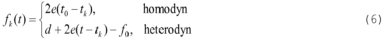
zum Signal d(t) bei. Somit können in diesem Fall aus einer - im heterodynen Fall zeitaufgelösten - Frequenzanalyse des Signals d(t) grundsätzlich die Laufzeiten tk direkt bestimmt werden, wobei die Auflösung allerdings noch grob ist. Genauere Resultate können durch die Berücksichtigung der Phaseninformation erhalten werden.In the case of a linear chirp according to equation (1), the kth echo carries the instantaneous frequency
to signal d ( t ) at. Thus, in this case, from a frequency analysis of the signal d (t) , which is time-resolved in the heterodyne case, basically the propagation times t k can be determined directly, although the resolution is still coarse. More accurate results can be obtained by considering the phase information.
Ein frequenzmoduliertes Verfahren mit kontinuierlicher Emission (FMCW-Verfahren) zur Abstandsmessung mit elektromagnetischer Strahlung im Radarbereich ist aus der
In
Ein FMCW-Modul 170 ist gemeinsam mit dem ADM 13 in der Strahllenkeinheit des Lasertrackers verbaut und verwendet dieselbe Laseraussendeoptik 51a wie der ADM 13. Das FMCW-Modul 170 weist eine Strahlquelle 171 mit Ansteuermitteln zur Erzeugung eines frequenzmodulierten Laserstrahls 176 mit kontinuierlich veränderlicher Frequenz auf. Der frequenzmodulierte Laserstrahl 176 wird zunächst auf einen ersten Strahlteiler 174 geleitet, wodurch ein Referenzstrahl 177 abgespalten wird, der auf ein Mischerelement 178 geleitet wird.An
Der andere Teil des frequenzmodulierten Laserstrahls 176 wird über einen zweiten Strahlteiler 175 in den gemeinsamen Strahlgang mit der Messstrahlung des ADM 13 eingekoppelt und durch die Laseraussendeoptik 51a auf das zu vermessende entfernte Messobjekt 90 gelenkt. Von der diffus streuenden Oberfläche des Messobjekts 90 remittierte Strahlung 181 des frequenzmodulierten Laserstrahls 176 gelangt teilweise durch die (hier rein beispielhaft separat von der Laseraussendeoptik 51a ausgeführte) Laserempfangsoptik 51b wieder in die Strahllenkeinheit. In dieser wird die remittierte Strahlung 181 auf das Mischerelement 178 geleitet, in welchem die remittierte Strahlung 181 mit dem Referenzstrahl 177 homodyn oder heterodyn gemischt wird. Optional kann die remittierte Strahlung 181 zuvor mittels eines HF-Vorverstärkers verstärkt worden sein.The other part of the frequency-modulated
Das entstandene Mischsignal 182 wird dann zum Detektor 172 des FMCW-Moduls 170 geführt, insbesondere kann das Mischsignal dabei auch über einen Tiefpassfilter und einen Basisbandverstärker zum Detektor 172 geführt werden, der insbesondere als Analog/Digitalwandler ausgestaltet sein kann. Durch eine Recheneinheit 173 kann dann auf bekannte Art und Weise ein Frequenzunterschied, d. h. insbesondere ein Abstand zwischen den Frequenzen des Referenzstrahls 177 und der remittierten Strahlung 181, ermittelt werden und daraus die Entfernung zum Messobjekt 90 berechnet werden.The resulting
Bei den in den
In einer weiteren, in
Es versteht sich, dass diese dargestellten Figuren nur mögliche Ausführungsbeispiele schematisch darstellen. Die verschiedenen Ansätze können erfindungsgemäss ebenso miteinander sowie mit Systemen und Verfahren zum Vermessen von Oberflächen bzw. Objekten und mit Vermessungsgeräten des Stands der Technik kombiniert werden.It is understood that these illustrated figures represent only possible embodiments schematically. According to the invention, the various approaches can also be combined with one another and with systems and methods for measuring surfaces or objects and with surveying devices of the prior art.
Claims (16)
wobei die Strahllenkeinheit (10) aufweist
dadurch gekennzeichnet, dass
wherein the beam steering unit (10)
characterized in that
dadurch gekennzeichnet, dass
ein Teil der zweiten Messstrahlung (76) als Referenzstrahl (77) dem Detektor (72) zuleitbar ist, insbesondere mittels eines im Strahlgang der zweiten Messstrahlung (76) in der Strahllenkeinheit (10) bereitgestellten ersten Strahlteilers (74).Laser tracker (1) according to claim 1,
characterized in that
a part of the second measuring radiation (76) as a reference beam (77) can be fed to the detector (72), in particular by means of a first beam splitter (74) provided in the beam path of the second measuring radiation (76) in the beam steering unit (10).
gekennzeichnet durch
eine Strahlempfangseinheit (80), die ausgestaltet ist, durch die Laseraussende- und -empfangsoptik (51) in die Strahllenkeinheit (10) eingetretene remittierte Strahlung (81, 181) zur zweiten optischen Distanzmesseinheit (170) zu leiten,
wobei die Strahlempfangseinheit (80) einen Paraboloid-Spiegel (85) mit einer parabolisch ausgestalteten Spiegeloberfläche aufweist, wobei der Paraboloid-Spiegel (85) dazu ausgestaltet ist, auf der Spiegeloberfläche auftreffende remittierte Strahlung (81, 181) in einem Brennpunkt zu bündeln, und insbesondere dazu ausgestaltet ist, in einem Zentrum der Spiegeloberfläche auftreffende remittierte Strahlung (81, 181) in einem Winkel von 65° bis 75°, insbesondere 70°, zu reflektieren,
insbesondere wobei
marked by
a beam receiving unit (80) configured to direct remitted radiation (81, 181) entered into the beam steering unit (10) through the laser emitting and receiving optics (51) to the second optical distance measuring unit (170),
wherein the beam receiving unit (80) comprises a paraboloidal mirror (85) having a parabolically configured mirror surface, the paraboloidal mirror (85) being configured to reflect remitted on the mirror surface To focus radiation (81, 181) in a focal point and in particular to reflect reflected radiation (81, 181) incident in a center of the mirror surface at an angle of 65 ° to 75 °, in particular 70 °,
in particular
wobei die Strahllenkeinheit (10) aufweist
dadurch gekennzeichnet, dass
wherein the beam steering unit (10)
characterized in that
dadurch gekennzeichnet, dass
die zweite optische Distanzmesseinheit (170)
characterized in that
the second optical distance measuring unit (170)
wobei die Strahllenkeinheit (10) aufweist
dadurch gekennzeichnet, dass
die erste optische Distanzmesseinheit und/oder die zweite optische Distanzmesseinheit (70, 170) für eine frequenzkammbasierte oder frequenzkammunterstützte Distanzmessung ausgestaltet sind.
wherein the beam steering unit (10)
characterized in that
the first optical distance measuring unit and / or the second optical distance measuring unit (70, 170) for a frequency-comb-based or frequency-comb-supported distance measurement are designed.
gekennzeichnet durch
eine Abtastfunktionalität, im Rahmen derer der Lasertracker (1) dazu ausgestaltet ist, mittels der zweiten Messstrahlung (76, 176) eine Vielzahl von Entfernungsmessungen zu einer Vielzahl von Messpunkten auf der Oberfläche (92) des Messobjektes (90) durchzuführen, wobei die Steuerungs- und Verarbeitungseinheit (73, 173) derart ausgebildet ist, dass
marked by
a scanning functionality in which the laser tracker (1) is configured to perform a plurality of distance measurements at a plurality of measurement points on the surface (92) of the measurement object (90) by means of the second measurement radiation (76, 176). and processing unit (73, 173) is designed such that
gekennzeichnet durch
eine Kalibrierungsfunktionalität zum Kalibrieren der ersten optischen Distanzmesseinheit und/oder der zweiten optischen Distanzmesseinheit (70, 170), wobei die Steuerungs- und Verarbeitungseinheit (73, 173) derart ausgebildet ist, dass
marked by
a calibration functionality for calibrating the first optical distance measuring unit and / or the second optical distance measuring unit (70, 170), wherein the control and processing unit (73, 173) is designed such that
dadurch gekennzeichnet, dass
characterized in that
gekennzeichnet durch
marked by
wobei das Verfahren umfasst
the method comprises
dadurch gekennzeichnet, dass
das zu vermessende Ziel eine diffus streuende Oberfläche (92) eines Messobjektes (90) ist, wobei
characterized in that
the target to be measured is a diffusely scattering surface (92) of a measurement object (90), wherein
dadurch gekennzeichnet, dass
das zu vermessende Ziel ein Retroreflektor (61) ist, insbesondere als Teil eines Messhilfsmittels (60), wobei
insbesondere wobei die erste Messstrahlung (36) und die zweite Messstrahlung (76, 176) auf den
Retroreflektor (61) emittiert werden, wobei eine mittels der ersten Messstrahlung gemessene Entfernung (36) und eine mittels der zweiten Messstrahlung (76, 176) gemessene Entfernung zum Kalibrieren des ersten optischen Distanzmessers (12, 13) und/oder des WFD-Moduls (70) bzw. des FMCW-Moduls (170) verwendet werden, insbesondere wobei die erste Messstrahlung (36) und die zweite Messstrahlung (76, 176) gleichzeitig emittiert werden.
characterized in that
the target to be measured is a retroreflector (61), in particular as part of a measuring aid (60), wherein
in particular wherein the first measuring radiation (36) and the second measuring radiation (76, 176) are applied to the
Retroreflector (61) are emitted, wherein a measured by the first measuring radiation distance (36) and a measured by the second measuring radiation (76, 176) distance for calibrating the first optical distance meter (12, 13) and / or the WFD module ( 70) or the FMCW module (170) are used, in particular wherein the first measuring radiation (36) and the second measuring radiation (76, 176) are emitted simultaneously.
dadurch gekennzeichnet, dass
die Distanzmesseinheit zur frequenzkammbasierten oder frequenzkammunterstützten Distanzmessung ausgestaltet ist.
characterized in that
the distance measuring unit is designed for frequency-comb-based or frequency-comb-supported distance measurement.
Priority Applications (4)
| Application Number | Priority Date | Filing Date | Title |
|---|---|---|---|
| EP14197717.3A EP3032277B1 (en) | 2014-12-12 | 2014-12-12 | Laser tracker |
| CN201510848470.8A CN105699983B (en) | 2014-12-12 | 2015-11-27 | Laser tracker provides the method and computer readable storage medium of additional measurement function |
| US14/962,877 US10725179B2 (en) | 2014-12-12 | 2015-12-08 | Laser tracker |
| US15/974,181 US20180252814A1 (en) | 2014-12-12 | 2018-05-08 | Laser tracker |
Applications Claiming Priority (1)
| Application Number | Priority Date | Filing Date | Title |
|---|---|---|---|
| EP14197717.3A EP3032277B1 (en) | 2014-12-12 | 2014-12-12 | Laser tracker |
Publications (2)
| Publication Number | Publication Date |
|---|---|
| EP3032277A1 true EP3032277A1 (en) | 2016-06-15 |
| EP3032277B1 EP3032277B1 (en) | 2021-04-07 |
Family
ID=52102550
Family Applications (1)
| Application Number | Title | Priority Date | Filing Date |
|---|---|---|---|
| EP14197717.3A Active EP3032277B1 (en) | 2014-12-12 | 2014-12-12 | Laser tracker |
Country Status (3)
| Country | Link |
|---|---|
| US (2) | US10725179B2 (en) |
| EP (1) | EP3032277B1 (en) |
| CN (1) | CN105699983B (en) |
Cited By (3)
| Publication number | Priority date | Publication date | Assignee | Title |
|---|---|---|---|---|
| CN109239726A (en) * | 2018-08-30 | 2019-01-18 | 天津大学 | A kind of noncooperative target range-measurement system based on the double comb femto-second lasers of separate unit |
| CN110268280A (en) * | 2017-01-24 | 2019-09-20 | Hrl实验室有限责任公司 | Double frequency fmcw radar and method |
| EP3715911A1 (en) * | 2019-03-27 | 2020-09-30 | Baumer Electric AG | Sensor arrangement |
Families Citing this family (19)
| Publication number | Priority date | Publication date | Assignee | Title |
|---|---|---|---|---|
| US9746560B2 (en) | 2013-02-12 | 2017-08-29 | Faro Technologies, Inc. | Combination scanner and tracker device having a focusing mechanism |
| CN109891261B (en) * | 2016-07-28 | 2023-11-24 | 通用汽车环球科技运作有限责任公司 | Distributed vehicle laser radar system |
| CN106886027B (en) * | 2017-02-24 | 2020-04-10 | 上海诺司纬光电仪器有限公司 | Laser positioning device and laser positioning method |
| CN107064950A (en) * | 2017-02-24 | 2017-08-18 | 上海诺司纬光电仪器有限公司 | Laser locating apparatus and laser positioning method |
| EP3404361B1 (en) | 2017-05-18 | 2019-07-17 | Leica Geosystems AG | Light receiver |
| CN107186714B (en) * | 2017-05-25 | 2019-11-26 | 英华达(上海)科技有限公司 | A kind of accurate positioning method, positioning system and robot device |
| KR20200088319A (en) * | 2017-11-17 | 2020-07-22 | 트리나미엑스 게엠베하 | A detector that determines the position of at least one object |
| CN112292613A (en) * | 2018-05-10 | 2021-01-29 | 我们科技股份有限公司 | LIDAR system based on multi-channel laser modules for simultaneous beam scanning of a target environment |
| CN108732553B (en) * | 2018-06-01 | 2022-02-01 | 北京航空航天大学 | Laser radar waveform time identification method and online ranging system |
| EP3627100B1 (en) * | 2018-09-20 | 2021-12-01 | Hexagon Technology Center GmbH | Retro reflector with fisheye lens |
| EP3693698A1 (en) * | 2019-02-05 | 2020-08-12 | Leica Geosystems AG | Measuring device with event-based camera |
| JP7015802B2 (en) * | 2019-03-18 | 2022-02-03 | 株式会社東芝 | Electronic devices and methods |
| CN109991585A (en) * | 2019-03-25 | 2019-07-09 | 深圳市速腾聚创科技有限公司 | The Method of Adjustment of laser radar and laser radar |
| CN114026407A (en) * | 2019-07-04 | 2022-02-08 | 柯尼卡美能达株式会社 | Spectroscopic measuring instrument |
| CN112771403B (en) | 2019-09-04 | 2024-02-27 | 深圳市速腾聚创科技有限公司 | Laser radar |
| CN111948178B (en) * | 2020-08-18 | 2023-09-29 | 中电科思仪科技股份有限公司 | Portable radar scattering characteristic testing device and method |
| CN112595231A (en) * | 2020-12-10 | 2021-04-02 | 上海镭隆科技发展有限公司 | Two-dimensional follow-up system dynamic monitoring device and method based on intelligent image recognition |
| CN112556579A (en) * | 2020-12-25 | 2021-03-26 | 深圳市中图仪器股份有限公司 | Six-degree-of-freedom space coordinate position and attitude measuring device |
| CN113890608B (en) * | 2021-08-27 | 2022-07-12 | 上海遥目科技有限公司 | Device and method for measuring laser communication receiving-transmitting registration precision |
Citations (20)
| Publication number | Priority date | Publication date | Assignee | Title |
|---|---|---|---|---|
| EP0553266A1 (en) | 1990-10-15 | 1993-08-04 | Waldean A Schulz | Method and apparatus for three-dimensional non-contact shape sensing. |
| DE19610970A1 (en) | 1996-03-20 | 1997-09-25 | Reinhard Dipl Ing Stolle | Radar information evaluation process on distance and speed |
| WO1997040342A2 (en) | 1996-04-24 | 1997-10-30 | Cyra Technologies, Inc. | Integrated system for imaging and modeling three-dimensional objects |
| US5973788A (en) | 1995-10-12 | 1999-10-26 | Metronor Asa | System for point-by-point measuring of spatial coordinates |
| WO2003062744A1 (en) | 2002-01-16 | 2003-07-31 | Faro Technologies, Inc. | Laser-based coordinate measuring device and laser-based method for measuring coordinates |
| WO2004036145A1 (en) | 2002-10-12 | 2004-04-29 | Leica Geosystems Ag | Electronic display and control device for a measuring device |
| US20060066836A1 (en) * | 2004-09-30 | 2006-03-30 | Bridges Robert E | Absolute distance meter that measures a moving retroreflector |
| EP1645890A1 (en) * | 2004-10-09 | 2006-04-12 | Leica Geosystems AG | Method for measuring distances including the determination of the non-ideal characteristics of the chirp |
| WO2007079600A1 (en) | 2006-01-13 | 2007-07-19 | Leica Geosystems Ag | Coordinate measurment instrument |
| EP1882959A1 (en) * | 2006-07-17 | 2008-01-30 | Leica Geosystems AG | Optical distance measuring method and corresponding optical range finder |
| WO2009103172A1 (en) | 2008-02-19 | 2009-08-27 | Leica Geosystems Ag | Electro-optical distance-measuring unit |
| WO2011076907A1 (en) * | 2009-12-22 | 2011-06-30 | Leica Geosystems Ag | Highly accurate distance measurement device |
| EP2523017A1 (en) * | 2011-05-13 | 2012-11-14 | Hexagon Technology Center GmbH | Calibration method for a device with scan functionality |
| EP2557391A1 (en) | 2011-08-12 | 2013-02-13 | Leica Geosystems AG | Measuring device for determining the spatial location of a measuring aid |
| EP2589982A1 (en) * | 2011-11-03 | 2013-05-08 | Leica Geosystems AG | Laser diode as interferometer laserbeam source in a laser tracker |
| EP1869397B1 (en) | 2005-03-17 | 2013-05-22 | Nikon Metrology NV | Precision length standard for coherent laser radar |
| EP2620745A1 (en) | 2012-01-30 | 2013-07-31 | Hexagon Technology Center GmbH | Measuring system with a measuring device and a scan module |
| DE102012001754A1 (en) * | 2012-01-30 | 2013-08-01 | Karlsruher Institut für Technologie | Multi-scale distance measurement with frequency combs |
| EP2634594A1 (en) | 2012-03-01 | 2013-09-04 | Leica Geosystems AG | Method for determining a change in distance by means of interferometry |
| CH706633A2 (en) | 2012-06-25 | 2013-12-31 | Leica Geosystems Ag | Laser tracker for determination of coordinates of spatial points, has control circuit for generating wavelength stabilization control signals depending on detected intensities of laser beam in two longitudinal modes, respectively |
Family Cites Families (6)
| Publication number | Priority date | Publication date | Assignee | Title |
|---|---|---|---|---|
| US6324455B1 (en) | 1998-11-05 | 2001-11-27 | Trimble Navigation Ltd | Laser level selection |
| US7800758B1 (en) | 1999-07-23 | 2010-09-21 | Faro Laser Trackers, Llc | Laser-based coordinate measuring device and laser-based method for measuring coordinates |
| US8125629B2 (en) | 2006-01-13 | 2012-02-28 | Leica Geosystems Ag | Tracking method and measuring system comprising a laser tracker |
| US7454265B2 (en) | 2006-05-10 | 2008-11-18 | The Boeing Company | Laser and Photogrammetry merged process |
| US8619265B2 (en) * | 2011-03-14 | 2013-12-31 | Faro Technologies, Inc. | Automatic measurement of dimensional data with a laser tracker |
| US9036134B2 (en) * | 2013-02-12 | 2015-05-19 | Faro Technologies, Inc. | Multi-mode optical measurement device and method of operation |
-
2014
- 2014-12-12 EP EP14197717.3A patent/EP3032277B1/en active Active
-
2015
- 2015-11-27 CN CN201510848470.8A patent/CN105699983B/en active Active
- 2015-12-08 US US14/962,877 patent/US10725179B2/en active Active
-
2018
- 2018-05-08 US US15/974,181 patent/US20180252814A1/en not_active Abandoned
Patent Citations (21)
| Publication number | Priority date | Publication date | Assignee | Title |
|---|---|---|---|---|
| EP0553266A1 (en) | 1990-10-15 | 1993-08-04 | Waldean A Schulz | Method and apparatus for three-dimensional non-contact shape sensing. |
| US5973788A (en) | 1995-10-12 | 1999-10-26 | Metronor Asa | System for point-by-point measuring of spatial coordinates |
| DE19610970A1 (en) | 1996-03-20 | 1997-09-25 | Reinhard Dipl Ing Stolle | Radar information evaluation process on distance and speed |
| WO1997040342A2 (en) | 1996-04-24 | 1997-10-30 | Cyra Technologies, Inc. | Integrated system for imaging and modeling three-dimensional objects |
| WO2003062744A1 (en) | 2002-01-16 | 2003-07-31 | Faro Technologies, Inc. | Laser-based coordinate measuring device and laser-based method for measuring coordinates |
| WO2004036145A1 (en) | 2002-10-12 | 2004-04-29 | Leica Geosystems Ag | Electronic display and control device for a measuring device |
| US20060066836A1 (en) * | 2004-09-30 | 2006-03-30 | Bridges Robert E | Absolute distance meter that measures a moving retroreflector |
| EP1645890A1 (en) * | 2004-10-09 | 2006-04-12 | Leica Geosystems AG | Method for measuring distances including the determination of the non-ideal characteristics of the chirp |
| WO2006040263A1 (en) | 2004-10-09 | 2006-04-20 | Leica Geosystems Ag | Electro-optical method for measuring distance and detecting a non-ideal chirp profile |
| EP1869397B1 (en) | 2005-03-17 | 2013-05-22 | Nikon Metrology NV | Precision length standard for coherent laser radar |
| WO2007079600A1 (en) | 2006-01-13 | 2007-07-19 | Leica Geosystems Ag | Coordinate measurment instrument |
| EP1882959A1 (en) * | 2006-07-17 | 2008-01-30 | Leica Geosystems AG | Optical distance measuring method and corresponding optical range finder |
| WO2009103172A1 (en) | 2008-02-19 | 2009-08-27 | Leica Geosystems Ag | Electro-optical distance-measuring unit |
| WO2011076907A1 (en) * | 2009-12-22 | 2011-06-30 | Leica Geosystems Ag | Highly accurate distance measurement device |
| EP2523017A1 (en) * | 2011-05-13 | 2012-11-14 | Hexagon Technology Center GmbH | Calibration method for a device with scan functionality |
| EP2557391A1 (en) | 2011-08-12 | 2013-02-13 | Leica Geosystems AG | Measuring device for determining the spatial location of a measuring aid |
| EP2589982A1 (en) * | 2011-11-03 | 2013-05-08 | Leica Geosystems AG | Laser diode as interferometer laserbeam source in a laser tracker |
| EP2620745A1 (en) | 2012-01-30 | 2013-07-31 | Hexagon Technology Center GmbH | Measuring system with a measuring device and a scan module |
| DE102012001754A1 (en) * | 2012-01-30 | 2013-08-01 | Karlsruher Institut für Technologie | Multi-scale distance measurement with frequency combs |
| EP2634594A1 (en) | 2012-03-01 | 2013-09-04 | Leica Geosystems AG | Method for determining a change in distance by means of interferometry |
| CH706633A2 (en) | 2012-06-25 | 2013-12-31 | Leica Geosystems Ag | Laser tracker for determination of coordinates of spatial points, has control circuit for generating wavelength stabilization control signals depending on detected intensities of laser beam in two longitudinal modes, respectively |
Non-Patent Citations (1)
| Title |
|---|
| N. R. NEWBURY; T.-A. LIU; I. CODDINGTON; F. GIORGETTA; E. BAUMANN; W. C. SWANN: "Frequency-Comb Based Approaches to Precision Ranging Laser Radar", NATIONAL INSTITUTE OF STANDARDS AND TECHNOLOGY |
Cited By (6)
| Publication number | Priority date | Publication date | Assignee | Title |
|---|---|---|---|---|
| CN110268280A (en) * | 2017-01-24 | 2019-09-20 | Hrl实验室有限责任公司 | Double frequency fmcw radar and method |
| CN110268280B (en) * | 2017-01-24 | 2023-08-08 | Hrl实验室有限责任公司 | Dual-frequency FMCW radar and method |
| CN109239726A (en) * | 2018-08-30 | 2019-01-18 | 天津大学 | A kind of noncooperative target range-measurement system based on the double comb femto-second lasers of separate unit |
| CN109239726B (en) * | 2018-08-30 | 2022-12-06 | 天津大学 | Non-cooperative target ranging system based on single double-comb femtosecond laser |
| EP3715911A1 (en) * | 2019-03-27 | 2020-09-30 | Baumer Electric AG | Sensor arrangement |
| CN111751819A (en) * | 2019-03-27 | 2020-10-09 | 宝盟电气股份公司 | Sensor device |
Also Published As
| Publication number | Publication date |
|---|---|
| EP3032277B1 (en) | 2021-04-07 |
| CN105699983B (en) | 2019-07-09 |
| CN105699983A (en) | 2016-06-22 |
| US20160170024A1 (en) | 2016-06-16 |
| US20180252814A1 (en) | 2018-09-06 |
| US10725179B2 (en) | 2020-07-28 |
Similar Documents
| Publication | Publication Date | Title |
|---|---|---|
| EP3032277B1 (en) | Laser tracker | |
| EP3220163B1 (en) | Laser tracker with two measuring function alities | |
| EP2820444B1 (en) | Method for determining a change in distance by means of interferometry | |
| EP2810020B1 (en) | Surveying device with scan functionality and single-point measuring mode | |
| EP2746806B1 (en) | Self-calibrating laser tracker and auto calibration technique | |
| DE102004037137B4 (en) | Method and device for distance measurement | |
| EP2980526B1 (en) | Coordinate measuring device and method | |
| EP2810019B1 (en) | Measuring system with a measuring device and a scan module | |
| EP2801841B1 (en) | Laser tracker with a target detecting unit for a target tracking system and orientation detection | |
| EP3165876A2 (en) | Opto-electronic measuring device | |
| EP2201330B1 (en) | Distance-measuring method for a device projecting a reference line, and such a device | |
| EP0987564B1 (en) | Device for measuring distance | |
| EP2773980B1 (en) | Laser diode as interferometer laserbeam source in a laser tracker | |
| EP2805180B1 (en) | Laser tracker with graphical targeting functionality | |
| EP2875383B1 (en) | Laser tracker with calibration unit for self-calibration | |
| DE112012001713T5 (en) | Laser detector with six degrees of freedom, which cooperates with a remote sensor | |
| DE69005106T2 (en) | ARRANGEMENT FOR CREATING OR DETERMINING THE LOCATION OF A MEASURING POINT. | |
| EP1766435A1 (en) | Scanning device for measuring the contours of an object | |
| CN108226902A (en) | A kind of face battle array lidar measurement system | |
| Wang et al. | A compact in situ ranging LiDAR and performance evaluation | |
| EP4298459A1 (en) | Laser tracker having two measurement functionalities and fmcw distance measurement | |
| WO2011036033A1 (en) | Method and device for determining the orientation and position of an object | |
| WO2015003833A1 (en) | Determination of a distance and an angle in relation to a plane by means of a plurality of distance measurements |
Legal Events
| Date | Code | Title | Description |
|---|---|---|---|
| PUAI | Public reference made under article 153(3) epc to a published international application that has entered the european phase |
Free format text: ORIGINAL CODE: 0009012 |
|
| AK | Designated contracting states |
Kind code of ref document: A1 Designated state(s): AL AT BE BG CH CY CZ DE DK EE ES FI FR GB GR HR HU IE IS IT LI LT LU LV MC MK MT NL NO PL PT RO RS SE SI SK SM TR |
|
| AX | Request for extension of the european patent |
Extension state: BA ME |
|
| STAA | Information on the status of an ep patent application or granted ep patent |
Free format text: STATUS: REQUEST FOR EXAMINATION WAS MADE |
|
| 17P | Request for examination filed |
Effective date: 20161118 |
|
| RBV | Designated contracting states (corrected) |
Designated state(s): AL AT BE BG CH CY CZ DE DK EE ES FI FR GB GR HR HU IE IS IT LI LT LU LV MC MK MT NL NO PL PT RO RS SE SI SK SM TR |
|
| STAA | Information on the status of an ep patent application or granted ep patent |
Free format text: STATUS: EXAMINATION IS IN PROGRESS |
|
| 17Q | First examination report despatched |
Effective date: 20190712 |
|
| GRAP | Despatch of communication of intention to grant a patent |
Free format text: ORIGINAL CODE: EPIDOSNIGR1 |
|
| STAA | Information on the status of an ep patent application or granted ep patent |
Free format text: STATUS: GRANT OF PATENT IS INTENDED |
|
| RIN1 | Information on inventor provided before grant (corrected) |
Inventor name: LUETHI, THOMAS Inventor name: BOECKEM, BURKHARD Inventor name: FUCHS, SIMON |
|
| INTG | Intention to grant announced |
Effective date: 20201106 |
|
| GRAS | Grant fee paid |
Free format text: ORIGINAL CODE: EPIDOSNIGR3 |
|
| GRAA | (expected) grant |
Free format text: ORIGINAL CODE: 0009210 |
|
| STAA | Information on the status of an ep patent application or granted ep patent |
Free format text: STATUS: THE PATENT HAS BEEN GRANTED |
|
| AK | Designated contracting states |
Kind code of ref document: B1 Designated state(s): AL AT BE BG CH CY CZ DE DK EE ES FI FR GB GR HR HU IE IS IT LI LT LU LV MC MK MT NL NO PL PT RO RS SE SI SK SM TR |
|
| REG | Reference to a national code |
Ref country code: GB Ref legal event code: FG4D Free format text: NOT ENGLISH |
|
| REG | Reference to a national code |
Ref country code: AT Ref legal event code: REF Ref document number: 1380393 Country of ref document: AT Kind code of ref document: T Effective date: 20210415 Ref country code: CH Ref legal event code: EP |
|
| REG | Reference to a national code |
Ref country code: DE Ref legal event code: R096 Ref document number: 502014015456 Country of ref document: DE |
|
| REG | Reference to a national code |
Ref country code: IE Ref legal event code: FG4D Free format text: LANGUAGE OF EP DOCUMENT: GERMAN |
|
| REG | Reference to a national code |
Ref country code: LT Ref legal event code: MG9D |
|
| REG | Reference to a national code |
Ref country code: NL Ref legal event code: MP Effective date: 20210407 |
|
| PG25 | Lapsed in a contracting state [announced via postgrant information from national office to epo] |
Ref country code: FI Free format text: LAPSE BECAUSE OF FAILURE TO SUBMIT A TRANSLATION OF THE DESCRIPTION OR TO PAY THE FEE WITHIN THE PRESCRIBED TIME-LIMIT Effective date: 20210407 Ref country code: NL Free format text: LAPSE BECAUSE OF FAILURE TO SUBMIT A TRANSLATION OF THE DESCRIPTION OR TO PAY THE FEE WITHIN THE PRESCRIBED TIME-LIMIT Effective date: 20210407 Ref country code: LT Free format text: LAPSE BECAUSE OF FAILURE TO SUBMIT A TRANSLATION OF THE DESCRIPTION OR TO PAY THE FEE WITHIN THE PRESCRIBED TIME-LIMIT Effective date: 20210407 Ref country code: BG Free format text: LAPSE BECAUSE OF FAILURE TO SUBMIT A TRANSLATION OF THE DESCRIPTION OR TO PAY THE FEE WITHIN THE PRESCRIBED TIME-LIMIT Effective date: 20210707 Ref country code: HR Free format text: LAPSE BECAUSE OF FAILURE TO SUBMIT A TRANSLATION OF THE DESCRIPTION OR TO PAY THE FEE WITHIN THE PRESCRIBED TIME-LIMIT Effective date: 20210407 |
|
| PG25 | Lapsed in a contracting state [announced via postgrant information from national office to epo] |
Ref country code: ES Free format text: LAPSE BECAUSE OF FAILURE TO SUBMIT A TRANSLATION OF THE DESCRIPTION OR TO PAY THE FEE WITHIN THE PRESCRIBED TIME-LIMIT Effective date: 20210407 Ref country code: PL Free format text: LAPSE BECAUSE OF FAILURE TO SUBMIT A TRANSLATION OF THE DESCRIPTION OR TO PAY THE FEE WITHIN THE PRESCRIBED TIME-LIMIT Effective date: 20210407 Ref country code: PT Free format text: LAPSE BECAUSE OF FAILURE TO SUBMIT A TRANSLATION OF THE DESCRIPTION OR TO PAY THE FEE WITHIN THE PRESCRIBED TIME-LIMIT Effective date: 20210809 Ref country code: NO Free format text: LAPSE BECAUSE OF FAILURE TO SUBMIT A TRANSLATION OF THE DESCRIPTION OR TO PAY THE FEE WITHIN THE PRESCRIBED TIME-LIMIT Effective date: 20210707 Ref country code: RS Free format text: LAPSE BECAUSE OF FAILURE TO SUBMIT A TRANSLATION OF THE DESCRIPTION OR TO PAY THE FEE WITHIN THE PRESCRIBED TIME-LIMIT Effective date: 20210407 Ref country code: SE Free format text: LAPSE BECAUSE OF FAILURE TO SUBMIT A TRANSLATION OF THE DESCRIPTION OR TO PAY THE FEE WITHIN THE PRESCRIBED TIME-LIMIT Effective date: 20210407 Ref country code: GR Free format text: LAPSE BECAUSE OF FAILURE TO SUBMIT A TRANSLATION OF THE DESCRIPTION OR TO PAY THE FEE WITHIN THE PRESCRIBED TIME-LIMIT Effective date: 20210708 Ref country code: IS Free format text: LAPSE BECAUSE OF FAILURE TO SUBMIT A TRANSLATION OF THE DESCRIPTION OR TO PAY THE FEE WITHIN THE PRESCRIBED TIME-LIMIT Effective date: 20210807 Ref country code: LV Free format text: LAPSE BECAUSE OF FAILURE TO SUBMIT A TRANSLATION OF THE DESCRIPTION OR TO PAY THE FEE WITHIN THE PRESCRIBED TIME-LIMIT Effective date: 20210407 |
|
| REG | Reference to a national code |
Ref country code: DE Ref legal event code: R097 Ref document number: 502014015456 Country of ref document: DE |
|
| PG25 | Lapsed in a contracting state [announced via postgrant information from national office to epo] |
Ref country code: RO Free format text: LAPSE BECAUSE OF FAILURE TO SUBMIT A TRANSLATION OF THE DESCRIPTION OR TO PAY THE FEE WITHIN THE PRESCRIBED TIME-LIMIT Effective date: 20210407 Ref country code: SM Free format text: LAPSE BECAUSE OF FAILURE TO SUBMIT A TRANSLATION OF THE DESCRIPTION OR TO PAY THE FEE WITHIN THE PRESCRIBED TIME-LIMIT Effective date: 20210407 Ref country code: SK Free format text: LAPSE BECAUSE OF FAILURE TO SUBMIT A TRANSLATION OF THE DESCRIPTION OR TO PAY THE FEE WITHIN THE PRESCRIBED TIME-LIMIT Effective date: 20210407 Ref country code: EE Free format text: LAPSE BECAUSE OF FAILURE TO SUBMIT A TRANSLATION OF THE DESCRIPTION OR TO PAY THE FEE WITHIN THE PRESCRIBED TIME-LIMIT Effective date: 20210407 Ref country code: CZ Free format text: LAPSE BECAUSE OF FAILURE TO SUBMIT A TRANSLATION OF THE DESCRIPTION OR TO PAY THE FEE WITHIN THE PRESCRIBED TIME-LIMIT Effective date: 20210407 Ref country code: DK Free format text: LAPSE BECAUSE OF FAILURE TO SUBMIT A TRANSLATION OF THE DESCRIPTION OR TO PAY THE FEE WITHIN THE PRESCRIBED TIME-LIMIT Effective date: 20210407 |
|
| PLBE | No opposition filed within time limit |
Free format text: ORIGINAL CODE: 0009261 |
|
| STAA | Information on the status of an ep patent application or granted ep patent |
Free format text: STATUS: NO OPPOSITION FILED WITHIN TIME LIMIT |
|
| 26N | No opposition filed |
Effective date: 20220110 |
|
| PG25 | Lapsed in a contracting state [announced via postgrant information from national office to epo] |
Ref country code: IS Free format text: LAPSE BECAUSE OF FAILURE TO SUBMIT A TRANSLATION OF THE DESCRIPTION OR TO PAY THE FEE WITHIN THE PRESCRIBED TIME-LIMIT Effective date: 20210807 Ref country code: AL Free format text: LAPSE BECAUSE OF FAILURE TO SUBMIT A TRANSLATION OF THE DESCRIPTION OR TO PAY THE FEE WITHIN THE PRESCRIBED TIME-LIMIT Effective date: 20210407 |
|
| PG25 | Lapsed in a contracting state [announced via postgrant information from national office to epo] |
Ref country code: MC Free format text: LAPSE BECAUSE OF FAILURE TO SUBMIT A TRANSLATION OF THE DESCRIPTION OR TO PAY THE FEE WITHIN THE PRESCRIBED TIME-LIMIT Effective date: 20210407 Ref country code: IT Free format text: LAPSE BECAUSE OF FAILURE TO SUBMIT A TRANSLATION OF THE DESCRIPTION OR TO PAY THE FEE WITHIN THE PRESCRIBED TIME-LIMIT Effective date: 20210407 |
|
| REG | Reference to a national code |
Ref country code: CH Ref legal event code: PL |
|
| REG | Reference to a national code |
Ref country code: BE Ref legal event code: MM Effective date: 20211231 |
|
| PG25 | Lapsed in a contracting state [announced via postgrant information from national office to epo] |
Ref country code: LU Free format text: LAPSE BECAUSE OF NON-PAYMENT OF DUE FEES Effective date: 20211212 Ref country code: IE Free format text: LAPSE BECAUSE OF NON-PAYMENT OF DUE FEES Effective date: 20211212 |
|
| PG25 | Lapsed in a contracting state [announced via postgrant information from national office to epo] |
Ref country code: BE Free format text: LAPSE BECAUSE OF NON-PAYMENT OF DUE FEES Effective date: 20211231 |
|
| PG25 | Lapsed in a contracting state [announced via postgrant information from national office to epo] |
Ref country code: LI Free format text: LAPSE BECAUSE OF NON-PAYMENT OF DUE FEES Effective date: 20211231 Ref country code: CH Free format text: LAPSE BECAUSE OF NON-PAYMENT OF DUE FEES Effective date: 20211231 |
|
| REG | Reference to a national code |
Ref country code: AT Ref legal event code: MM01 Ref document number: 1380393 Country of ref document: AT Kind code of ref document: T Effective date: 20211212 |
|
| PG25 | Lapsed in a contracting state [announced via postgrant information from national office to epo] |
Ref country code: AT Free format text: LAPSE BECAUSE OF NON-PAYMENT OF DUE FEES Effective date: 20211212 |
|
| PG25 | Lapsed in a contracting state [announced via postgrant information from national office to epo] |
Ref country code: HU Free format text: LAPSE BECAUSE OF FAILURE TO SUBMIT A TRANSLATION OF THE DESCRIPTION OR TO PAY THE FEE WITHIN THE PRESCRIBED TIME-LIMIT; INVALID AB INITIO Effective date: 20141212 |
|
| PG25 | Lapsed in a contracting state [announced via postgrant information from national office to epo] |
Ref country code: CY Free format text: LAPSE BECAUSE OF FAILURE TO SUBMIT A TRANSLATION OF THE DESCRIPTION OR TO PAY THE FEE WITHIN THE PRESCRIBED TIME-LIMIT Effective date: 20210407 |
|
| PGFP | Annual fee paid to national office [announced via postgrant information from national office to epo] |
Ref country code: GB Payment date: 20231220 Year of fee payment: 10 |
|
| PGFP | Annual fee paid to national office [announced via postgrant information from national office to epo] |
Ref country code: FR Payment date: 20231221 Year of fee payment: 10 Ref country code: DE Payment date: 20231214 Year of fee payment: 10 |
|
| PG25 | Lapsed in a contracting state [announced via postgrant information from national office to epo] |
Ref country code: MK Free format text: LAPSE BECAUSE OF FAILURE TO SUBMIT A TRANSLATION OF THE DESCRIPTION OR TO PAY THE FEE WITHIN THE PRESCRIBED TIME-LIMIT Effective date: 20210407 |