EP3032041B1 - Rotor heat shield and method for securing the same into a rotor assembly - Google Patents
Rotor heat shield and method for securing the same into a rotor assembly Download PDFInfo
- Publication number
- EP3032041B1 EP3032041B1 EP14196806.5A EP14196806A EP3032041B1 EP 3032041 B1 EP3032041 B1 EP 3032041B1 EP 14196806 A EP14196806 A EP 14196806A EP 3032041 B1 EP3032041 B1 EP 3032041B1
- Authority
- EP
- European Patent Office
- Prior art keywords
- rotor
- heat shield
- groove
- opening
- assembly
- Prior art date
- Legal status (The legal status is an assumption and is not a legal conclusion. Google has not performed a legal analysis and makes no representation as to the accuracy of the status listed.)
- Active
Links
- 238000000034 method Methods 0.000 title claims description 13
- 230000000903 blocking effect Effects 0.000 claims description 18
- 238000005452 bending Methods 0.000 claims description 5
- 230000001419 dependent effect Effects 0.000 description 2
- 239000002184 metal Substances 0.000 description 2
- 238000005336 cracking Methods 0.000 description 1
- 238000003780 insertion Methods 0.000 description 1
- 230000037431 insertion Effects 0.000 description 1
- 230000002452 interceptive effect Effects 0.000 description 1
- 238000003754 machining Methods 0.000 description 1
- 239000000463 material Substances 0.000 description 1
- 238000012986 modification Methods 0.000 description 1
- 230000004048 modification Effects 0.000 description 1
- 239000007787 solid Substances 0.000 description 1
Images


Classifications
-
- F—MECHANICAL ENGINEERING; LIGHTING; HEATING; WEAPONS; BLASTING
- F01—MACHINES OR ENGINES IN GENERAL; ENGINE PLANTS IN GENERAL; STEAM ENGINES
- F01D—NON-POSITIVE DISPLACEMENT MACHINES OR ENGINES, e.g. STEAM TURBINES
- F01D5/00—Blades; Blade-carrying members; Heating, heat-insulating, cooling or antivibration means on the blades or the members
- F01D5/02—Blade-carrying members, e.g. rotors
- F01D5/08—Heating, heat-insulating or cooling means
-
- F—MECHANICAL ENGINEERING; LIGHTING; HEATING; WEAPONS; BLASTING
- F01—MACHINES OR ENGINES IN GENERAL; ENGINE PLANTS IN GENERAL; STEAM ENGINES
- F01D—NON-POSITIVE DISPLACEMENT MACHINES OR ENGINES, e.g. STEAM TURBINES
- F01D11/00—Preventing or minimising internal leakage of working-fluid, e.g. between stages
- F01D11/001—Preventing or minimising internal leakage of working-fluid, e.g. between stages for sealing space between stator blade and rotor
-
- F—MECHANICAL ENGINEERING; LIGHTING; HEATING; WEAPONS; BLASTING
- F01—MACHINES OR ENGINES IN GENERAL; ENGINE PLANTS IN GENERAL; STEAM ENGINES
- F01D—NON-POSITIVE DISPLACEMENT MACHINES OR ENGINES, e.g. STEAM TURBINES
- F01D11/00—Preventing or minimising internal leakage of working-fluid, e.g. between stages
- F01D11/005—Sealing means between non relatively rotating elements
- F01D11/006—Sealing the gap between rotor blades or blades and rotor
- F01D11/008—Sealing the gap between rotor blades or blades and rotor by spacer elements between the blades, e.g. independent interblade platforms
-
- F—MECHANICAL ENGINEERING; LIGHTING; HEATING; WEAPONS; BLASTING
- F02—COMBUSTION ENGINES; HOT-GAS OR COMBUSTION-PRODUCT ENGINE PLANTS
- F02C—GAS-TURBINE PLANTS; AIR INTAKES FOR JET-PROPULSION PLANTS; CONTROLLING FUEL SUPPLY IN AIR-BREATHING JET-PROPULSION PLANTS
- F02C7/00—Features, components parts, details or accessories, not provided for in, or of interest apart form groups F02C1/00 - F02C6/00; Air intakes for jet-propulsion plants
- F02C7/24—Heat or noise insulation
-
- F—MECHANICAL ENGINEERING; LIGHTING; HEATING; WEAPONS; BLASTING
- F05—INDEXING SCHEMES RELATING TO ENGINES OR PUMPS IN VARIOUS SUBCLASSES OF CLASSES F01-F04
- F05D—INDEXING SCHEME FOR ASPECTS RELATING TO NON-POSITIVE-DISPLACEMENT MACHINES OR ENGINES, GAS-TURBINES OR JET-PROPULSION PLANTS
- F05D2220/00—Application
- F05D2220/30—Application in turbines
- F05D2220/32—Application in turbines in gas turbines
-
- F—MECHANICAL ENGINEERING; LIGHTING; HEATING; WEAPONS; BLASTING
- F05—INDEXING SCHEMES RELATING TO ENGINES OR PUMPS IN VARIOUS SUBCLASSES OF CLASSES F01-F04
- F05D—INDEXING SCHEME FOR ASPECTS RELATING TO NON-POSITIVE-DISPLACEMENT MACHINES OR ENGINES, GAS-TURBINES OR JET-PROPULSION PLANTS
- F05D2230/00—Manufacture
- F05D2230/60—Assembly methods
-
- F—MECHANICAL ENGINEERING; LIGHTING; HEATING; WEAPONS; BLASTING
- F05—INDEXING SCHEMES RELATING TO ENGINES OR PUMPS IN VARIOUS SUBCLASSES OF CLASSES F01-F04
- F05D—INDEXING SCHEME FOR ASPECTS RELATING TO NON-POSITIVE-DISPLACEMENT MACHINES OR ENGINES, GAS-TURBINES OR JET-PROPULSION PLANTS
- F05D2240/00—Components
- F05D2240/20—Rotors
- F05D2240/24—Rotors for turbines
-
- F—MECHANICAL ENGINEERING; LIGHTING; HEATING; WEAPONS; BLASTING
- F05—INDEXING SCHEMES RELATING TO ENGINES OR PUMPS IN VARIOUS SUBCLASSES OF CLASSES F01-F04
- F05D—INDEXING SCHEME FOR ASPECTS RELATING TO NON-POSITIVE-DISPLACEMENT MACHINES OR ENGINES, GAS-TURBINES OR JET-PROPULSION PLANTS
- F05D2260/00—Function
- F05D2260/20—Heat transfer, e.g. cooling
- F05D2260/231—Preventing heat transfer
-
- F—MECHANICAL ENGINEERING; LIGHTING; HEATING; WEAPONS; BLASTING
- F05—INDEXING SCHEMES RELATING TO ENGINES OR PUMPS IN VARIOUS SUBCLASSES OF CLASSES F01-F04
- F05D—INDEXING SCHEME FOR ASPECTS RELATING TO NON-POSITIVE-DISPLACEMENT MACHINES OR ENGINES, GAS-TURBINES OR JET-PROPULSION PLANTS
- F05D2260/00—Function
- F05D2260/30—Retaining components in desired mutual position
Definitions
- the present invention generally relates to a rotor assembly, and in particular relates to an improved rotor heat shield element which provides an innovative configuration for securing the same into the rotor assembly.
- rotating machines typically have a rotor which has several rotor blade rows with a plurality of rotor blades, and generally also at least one rotor heat shield composed by a plurality of heat shield elements, wherein the rotor heat shield is arranged axially between two adjacent rotor blade rows.
- the heat shield elements are inserted sequentially into a correspondent groove engraved into the rotor assembly, such to form a circumferential heat shield.
- each heat shield element is circumferentially fixed by means of a lug disposed on a neighbouring blade, which is accommodated in a receiving slot formed on the heat shield element.
- US 2010/074731 discloses a rotor assembly for a gas turbine and a rotor heat shield element.
- the rotor heat shield element has a heat shield and base feet inserted into a circumferential groove in the rotor assembly and connected to the heat shield through a connection plate.
- the rotor heat shield element also comprises securing means for securing the rotor heat shield element to the rotor assembly.
- the securing means comprises a through-opening internally defined in the base feet and a fixing screw in the through-opening.
- the through-opening is internally shaped such to define a stepped region and the shape of the fixing screw matches the internal shape of the through-opening.
- the rotor heat shield element is secured to the rotor assembly in correspondence of the groove in which it is inserted.
- such connection is preferably achieved by means of a fixing plate, which does not interfere with the current assembly process of the rotor heat shield element.
- the present invention allows the removal of current fixation features on heat shields and blades, that is lugs and correspondent receiving slots respectively. Furthermore, since the heat shield is no longer connected to a blade but directly to the rotor assembly, there is more freedom in selecting the number of heat shield elements to be provided to form the circumferential heat shield.
- the through-opening may be T-shaped, L-shaped or alternatively U-shaped, It will be appreciated that other shapes may also be considered.
- the outlet may be located in the proximity the connection plate.
- the outlet is located in the proximity of a free end of the base feet.
- a rotor assembly for a gas turbine, the rotor assembly comprising a circumferential groove for receiving a plurality of base feet, wherein it further comprises rotor connection means configured to connect the base feet to the rotor assembly, the rotor connection means being located in correspondence of the groove.
- the rotor assembly further comprises a plurality of recesses equidistantly located on the lateral wall of the groove.
- a method for inserting and securing a rotor heat shield element into a rotor assembly including the steps of providing a rotor heat shield element comprising a base feet, wherein the base feet defines internally a through-opening having an inlet located on a bottom wall and an outlet on an opposed wall thereto of the base feet, the through-opening being internally shaped such to define at least one stepped region; inserting into the through-opening a fixing plate, the fixing plate having a shape adapted to substantially match the internal shape of said through-opening and comprising a blocking portion extending out from said outlet of the opposed wall when inserted into the base feet; introducing the rotor heat shield into a rotor assembly, the rotor assembly comprising a circumferential groove shaped such to receive said base feet, said groove further comprising at least a recess located on a lateral wall of the groove; positioning the rotor heat shield element in the groove such that the blocking portion of the fixing plate is substantially aligned with the
- the heat shield element 100 comprises connection means 101, in the form of receiving guides, which are adapted to host a lug provided on a correspondent blade, to which the heat shield element is secured.
- FIG. 2 This kind of connection, pertaining to the current practise, is schematically illustrated in next figure 2 .
- the rotor heat shield 100 is connected to a correspondent blade 200 by means of a lug 102 which is inserted into the receiving guide 101 of the shield element 100.
- the shield element is inserted into a circumferential groove 301 of the rotor assembly 300, and it is connected to the blade 200 which in turn is secured to the rotor assembly 300.
- FIG. 3 top and bottom views, it is shown a radial section of the heat shield element 1 according to the present invention, in a front view (left) and a lateral view (right).
- the heat shield element comprises a base feet 4, adapted to be inserted into a correspondent groove of a rotor assembly (not shown), and a connection plate 9 which links the base feet 4 to a heat shield (not depicted in the figure).
- the heat shield element 1 further comprises securing means adapted to secure the heat shield element to the rotor assembly.
- the securing means is advantageously configured to secure the heat shield element to the rotor assembly by cooperating with the groove in which the base feet 4 is inserted.
- the securing means comprises a through-opening 6 which is internally defined in the base feet 4.
- the through-opening 6 has an inlet 61 located on a bottom wall 41 of the base feet 4 and an outlet 62 located on a wall 42 which is opposed to the bottom wall 41.
- the through-opening 6 is internally shaped such to define a stepped region 7.
- the through-opening 6 shown here in this example is T-shaped, having two stepped regions, but it will be appreciated that other shapes can be chosen, as long as they provide a stepped region.
- a u-shape may be selected, still providing two stepped regions, or alternatively an L-shaped may be considered, the latter providing only one stepped region.
- the through-opening 6 may be obtained, starting from the rotor heat shield element 1 depicted on top view, with methodologies known to those who are skilled in the art, like for example through a machining process.
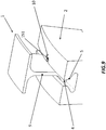
- FIG 4 there are shown the next steps necessary for securing the heat shield element 1 to a rotor assembly, now schematically depicted with numeral reference 2.
- a fixing plate 15 is then inserted into the through-opening 6.
- the fixing plate 15 has a shape which substantially matches the internal shape of the through-opening 6.
- the fixing plate 15 is subjected, during rotation of the rotor assembly, to an important centrifugal load.
- the stepped region 7 provided along the internal shape of the through-opening 6 is necessary to keep the fixing plate in position during operation of the machine.
- the fixing plate 15, in this non-limiting example, is T-shaped.
- the fixing plate 15 comprises a blocking portion 151 which extends out from the base feet 4, in particular from the outlet 62 of the wall 42.
- the through-opening 6 is disposed within the base feet 4 along a radial direction of the rotor assembly, when the heat shield element is inserted into the correspondent groove.
- the outlet 62 is located in the proximity of the connection plate 9, so that the fixing plate 15, and in particular the blocking element 151 lies adjacent to the connection plate 9.
- the outlet may be located anywhere along the opposed wall, and for example in the proximity of a free end of the base feet 4 (embodiment not shown).
- the blocking portion 151 is firstly bent along the wall 42 and then is straightened back following the vertical direction of the connection plate 9. Still making reference to figure 4 , bottom view, the heat shield element 1, including the fixing plate 15, is introduced into the rotor assembly 2.
- the rotor assembly 2 comprises a circumferential groove 5 adapted such to receive the base feet 4.
- the groove 5 of the rotor assembly 2 advantageously, comprises rotor connection means 10 which is configured to connect the base feet 4, and thus the rotor heat shield element 1, to the rotor assembly 2.
- the rotor connection means 10 is located in correspondence of the groove 5.
- the rotor connection means 10 comprises a recess 10, which is located on a lateral wall of the groove 5.
- the rotor heat shield element 1 is then positioned within the groove 5 such that the blocking portion 151 is substantially aligned with the recess 10. As a final step, the blocking portion 151 is bent towards the recess 10 to establish a solid connection between the rotor heat shield element 1 and the rotor assembly 2.
- the circumferential groove 5 of the rotor assembly 2 may comprise a plurality of recesses 10, equidistantly spaced along the lateral wall of the groove 5.
- the number of the recesses 10 engraved into the groove 5 may match the number of rotor heat shield elements 1 sequentially inserted into the groove 5, to finally form the complete circumferential heat shield. It will be appreciated that during such operation, each rotor heat shield element 1 is inserted into the groove 5 and positioned substantially in correspondence to the respective recess 10, in order to obtain the connection as above detailed.
- the complete rotor heat shield element 1 is pictured, now showing also a heat shield 8, which is connected to the base feet 4 through the connection plate 9.
- the base feet comprises securing means 6, that is the through-opening 6 which, in this example, is T-shaped and defines internally two stepped regions.
- the fixing plate 15 is then inserted into the through-opening 6, such that the blocking portion 151 extends out from the base feet 4 and it is disposed adjacent to the connection plate 9, as shown in figure 7 .
- the heat shield element 1 is introduced into the correspondent groove 5 of the rotor assembly 2, as shown in figure 8 .
- the element 1 is introduced such that the blocking element 151 is substantially aligned with the recess 10 engraved on the lateral wall of the groove 5.
- Figure 9 shows the final stage of the process when the blocking portion 151 is bent towards the recess 10. This way, circumferential movement of the rotor heat shield element 1 is prevented from the cooperation of the blocking portion 151 acting on the recess 10, whilst radial and axial movements of the element 1 are prevented by the cooperation of the base feet 4 inserted into the groove 5. This way stability of rotor heat shield element 1 is ensured.
- Last figure 10 shows in more detail the step of bending the blocking portion 151 into the recess 10.
- the fixing plate is made of metal. Indeed, such material is malleable and therefore can be deformed permanently without breaking or cracking. It will also be appreciated that the arrangement described above may be applied, mutatis mutandis, to any component which is installed radially by sliding components on a radial groove and that at the end of the assembly procedure further rotation of the components inside the groove needs to be completely avoided, so radially fixed, such as stator vanes or heat shields.
- through-opening 6 and rotor recess 10 may involve additional bending operations of the fixing plate against the base feet 4 and/or the connection plate 9. Such operations will occur after mounting the fixing plate 15 into the through-opening groove 6 and before mounting the rotor heat shield element 1 into the rotor assembly 2 in order to allow the rotor heat shield element 1 to slip along the circumferential groove 5 without the fixing plate 15 interfering.
- a second bending operation shall secure the fixing plate 15 into the rotor recess 10.
Landscapes
- Engineering & Computer Science (AREA)
- Mechanical Engineering (AREA)
- General Engineering & Computer Science (AREA)
- Chemical & Material Sciences (AREA)
- Combustion & Propulsion (AREA)
- Turbine Rotor Nozzle Sealing (AREA)
- Motor Or Generator Cooling System (AREA)
Description
- The present invention generally relates to a rotor assembly, and in particular relates to an improved rotor heat shield element which provides an innovative configuration for securing the same into the rotor assembly.
- As well known, in conventional gas turbines, rotating machines typically have a rotor which has several rotor blade rows with a plurality of rotor blades, and generally also at least one rotor heat shield composed by a plurality of heat shield elements, wherein the rotor heat shield is arranged axially between two adjacent rotor blade rows.
According to current practise, the heat shield elements are inserted sequentially into a correspondent groove engraved into the rotor assembly, such to form a circumferential heat shield. In particular, each heat shield element is circumferentially fixed by means of a lug disposed on a neighbouring blade, which is accommodated in a receiving slot formed on the heat shield element. This connection is established at outer diameters (where large circumferential forces are involved), close to hot gas path (typically hotter metal temperature). Therefore, in the consideration that each rotor shield element is connected to a correspondent blade, the number of shield elements has to be somehow dependent on the number of the blades, that is the shield elements are in the same number, or half, or a third and so on.
However, current design presents a number of drawbacks.
In fact, the presence of connecting lugs on the blades and corresponding receiving slots on heat shield elements determine a rather complex design to be carried out for both components. Furthermore, the lugs entail an undesirable weight increase of the blades.
Moreover, as the fixation is done at outer diameters of the machine, significant loads are transferred at the contact surfaces.
The present invention addresses these technical problems.
US 2010/074731 discloses a rotor assembly for a gas turbine and a rotor heat shield element. The rotor heat shield element has a heat shield and base feet inserted into a circumferential groove in the rotor assembly and connected to the heat shield through a connection plate. The rotor heat shield element also comprises securing means for securing the rotor heat shield element to the rotor assembly. The securing means comprises a through-opening internally defined in the base feet and a fixing screw in the through-opening. The through-opening is internally shaped such to define a stepped region and the shape of the fixing screw matches the internal shape of the through-opening. - It is an object of the present invention to solve the aforementioned technical problems with reference to the state of the art by providing an assembly comprising a rotor assembly for a gas turbine and a rotor heat shield element for the rotor assembly as substantially defined in
independent claim 1. - It is a further object of the present invention to provide a method for inserting and securing a rotor heat shield element into a rotor assembly as substantially defined in
independent claim 9.
Preferred embodiments are defined in correspondent dependent claims. - As it will appear clear from the detailed description of some exemplary, and not limiting, preferred embodiments of the invention, the rotor heat shield element is secured to the rotor assembly in correspondence of the groove in which it is inserted. In particular, as it will be detailed below, such connection is preferably achieved by means of a fixing plate, which does not interfere with the current assembly process of the rotor heat shield element.
Also, the present invention allows the removal of current fixation features on heat shields and blades, that is lugs and correspondent receiving slots respectively. Furthermore, since the heat shield is no longer connected to a blade but directly to the rotor assembly, there is more freedom in selecting the number of heat shield elements to be provided to form the circumferential heat shield.
Moreover, it will be appreciated that, as the fixation is established in correspondence to the groove of the rotor shaft, circumferential forces transmitted at the contact surfaces are significantly reduced with respect the prior art arrangement. In other words, anti-rotation stresses are transferred to a lower radius of the machine, and thus are reduced. - According to different preferred embodiments, the through-opening may be T-shaped, L-shaped or alternatively U-shaped, It will be appreciated that other shapes may also be considered.
- According to a further aspect of the invention the outlet may be located in the proximity the connection plate. Alternatively, the outlet is located in the proximity of a free end of the base feet.
- According to another aspect of the invention, it is provided a rotor assembly for a gas turbine, the rotor assembly comprising a circumferential groove for receiving a plurality of base feet, wherein it further comprises rotor connection means configured to connect the base feet to the rotor assembly, the rotor connection means being located in correspondence of the groove.
- According to a further preferred aspect of the invention, the rotor assembly further comprises a plurality of recesses equidistantly located on the lateral wall of the groove.
- It is also provided a method for inserting and securing a rotor heat shield element into a rotor assembly, the method including the steps of providing a rotor heat shield element comprising a base feet, wherein the base feet defines internally a through-opening having an inlet located on a bottom wall and an outlet on an opposed wall thereto of the base feet, the through-opening being internally shaped such to define at least one stepped region; inserting into the through-opening a fixing plate, the fixing plate having a shape adapted to substantially match the internal shape of said through-opening and comprising a blocking portion extending out from said outlet of the opposed wall when inserted into the base feet; introducing the rotor heat shield into a rotor assembly, the rotor assembly comprising a circumferential groove shaped such to receive said base feet, said groove further comprising at least a recess located on a lateral wall of the groove; positioning the rotor heat shield element in the groove such that the blocking portion of the fixing plate is substantially aligned with the recess; bending the blocking portion towards the recess such to prevent circumferential movement of the rotor heat shield element along the groove.
- The foregoing objects and many of the attendant advantages of this invention will become more readily appreciated as the same becomes better understood by reference to the following detailed description when taken in conjunction with the accompanying drawings, wherein:
-
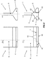
Figure 1 shows a perspective view of a rotor heat shield element according to the prior art; -
Figure 2 shows a radial section of an engagement between a rotor heat shield and a correspondent blade according to the prior art. -
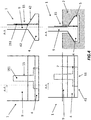
Figures 3-5 show a schematic radial section of a heat shield element and the steps of the method in sequence for securing the heat shield element to the rotor assembly; -
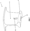
Figures 6-10 show the sequence of securing the heat shield element to the rotor assembly according to the present invention in perspective views. - With reference to
figure 1 , it is showed a rotorheat shield element 100 according to the prior art. In particular, theheat shield element 100 comprises connection means 101, in the form of receiving guides, which are adapted to host a lug provided on a correspondent blade, to which the heat shield element is secured. - This kind of connection, pertaining to the current practise, is schematically illustrated in next
figure 2 . As shown, therotor heat shield 100 is connected to acorrespondent blade 200 by means of alug 102 which is inserted into thereceiving guide 101 of theshield element 100. The shield element is inserted into acircumferential groove 301 of therotor assembly 300, and it is connected to theblade 200 which in turn is secured to therotor assembly 300. - With reference to
figure 3 , top and bottom views, it is shown a radial section of theheat shield element 1 according to the present invention, in a front view (left) and a lateral view (right). The heat shield element comprises abase feet 4, adapted to be inserted into a correspondent groove of a rotor assembly (not shown), and aconnection plate 9 which links thebase feet 4 to a heat shield (not depicted in the figure). With reference to thefigure 3 , bottom view, theheat shield element 1 further comprises securing means adapted to secure the heat shield element to the rotor assembly. In particular, as it will be explained below in detail, the securing means is advantageously configured to secure the heat shield element to the rotor assembly by cooperating with the groove in which thebase feet 4 is inserted.
In the preferred embodiment shown here as a non-limiting example, the securing means comprises a through-opening 6 which is internally defined in thebase feet 4. The through-opening 6 has aninlet 61 located on abottom wall 41 of thebase feet 4 and anoutlet 62 located on awall 42 which is opposed to thebottom wall 41. In particular, the through-opening 6 is internally shaped such to define astepped region 7. The through-opening 6 shown here in this example is T-shaped, having two stepped regions, but it will be appreciated that other shapes can be chosen, as long as they provide a stepped region. A u-shape may be selected, still providing two stepped regions, or alternatively an L-shaped may be considered, the latter providing only one stepped region.
The through-opening 6 may be obtained, starting from the rotorheat shield element 1 depicted on top view, with methodologies known to those who are skilled in the art, like for example through a machining process. - With reference to
figure 4 , there are shown the next steps necessary for securing theheat shield element 1 to a rotor assembly, now schematically depicted withnumeral reference 2. Afixing plate 15 is then inserted into the through-opening 6. As clearly visible in the figure, thefixing plate 15 has a shape which substantially matches the internal shape of the through-opening 6. As it will be appreciated, thefixing plate 15 is subjected, during rotation of the rotor assembly, to an important centrifugal load. Thus, thestepped region 7 provided along the internal shape of the through-opening 6 is necessary to keep the fixing plate in position during operation of the machine. Thefixing plate 15, in this non-limiting example, is T-shaped. Thefixing plate 15 comprises a blockingportion 151 which extends out from thebase feet 4, in particular from theoutlet 62 of thewall 42. Preferably, the through-opening 6 is disposed within thebase feet 4 along a radial direction of the rotor assembly, when the heat shield element is inserted into the correspondent groove. Such configuration is optimal for achieving an efficient and stable connection with the rotor assembly, as it will be clear in the following. According to a further preferred aspect, theoutlet 62 is located in the proximity of theconnection plate 9, so that the fixingplate 15, and in particular the blockingelement 151 lies adjacent to theconnection plate 9. Alternatively, the outlet may be located anywhere along the opposed wall, and for example in the proximity of a free end of the base feet 4 (embodiment not shown). In this case, the blockingportion 151 is firstly bent along thewall 42 and then is straightened back following the vertical direction of theconnection plate 9.
Still making reference tofigure 4 , bottom view, theheat shield element 1, including the fixingplate 15, is introduced into therotor assembly 2. Therotor assembly 2 comprises acircumferential groove 5 adapted such to receive thebase feet 4. - With now reference to next
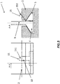
figure 5 , thegroove 5 of therotor assembly 2, advantageously, comprises rotor connection means 10 which is configured to connect thebase feet 4, and thus the rotorheat shield element 1, to therotor assembly 2. In particular, the rotor connection means 10 is located in correspondence of thegroove 5. In the preferred embodiment herewith described, the rotor connection means 10 comprises arecess 10, which is located on a lateral wall of thegroove 5. The rotorheat shield element 1 is then positioned within thegroove 5 such that the blockingportion 151 is substantially aligned with therecess 10. As a final step, the blockingportion 151 is bent towards therecess 10 to establish a solid connection between the rotorheat shield element 1 and therotor assembly 2.
It will be understood that thecircumferential groove 5 of therotor assembly 2 may comprise a plurality ofrecesses 10, equidistantly spaced along the lateral wall of thegroove 5. The number of therecesses 10 engraved into thegroove 5 may match the number of rotorheat shield elements 1 sequentially inserted into thegroove 5, to finally form the complete circumferential heat shield. It will be appreciated that during such operation, each rotorheat shield element 1 is inserted into thegroove 5 and positioned substantially in correspondence to therespective recess 10, in order to obtain the connection as above detailed.
The steps according to the method for inserting and securing the rotor heat shield element into the rotor assembly can be even better appreciated with reference to nextfigures 6-10 , where the components object to the present invention, that is the rotor heat shield and the rotor assembly, are shown in perspective views. - With reference to
figure 6 , the complete rotorheat shield element 1 is pictured, now showing also aheat shield 8, which is connected to thebase feet 4 through theconnection plate 9. The base feet comprises securing means 6, that is the through-opening 6 which, in this example, is T-shaped and defines internally two stepped regions. The fixingplate 15 is then inserted into the through-opening 6, such that the blockingportion 151 extends out from thebase feet 4 and it is disposed adjacent to theconnection plate 9, as shown infigure 7 . - After the insertion of the fixing
plate 15, theheat shield element 1 is introduced into thecorrespondent groove 5 of therotor assembly 2, as shown infigure 8 . In particular, theelement 1 is introduced such that the blockingelement 151 is substantially aligned with therecess 10 engraved on the lateral wall of thegroove 5. -
Figure 9 shows the final stage of the process when the blockingportion 151 is bent towards therecess 10. This way, circumferential movement of the rotorheat shield element 1 is prevented from the cooperation of the blockingportion 151 acting on therecess 10, whilst radial and axial movements of theelement 1 are prevented by the cooperation of thebase feet 4 inserted into thegroove 5. This way stability of rotorheat shield element 1 is ensured. - Last
figure 10 shows in more detail the step of bending the blockingportion 151 into therecess 10. Preferably, the fixing plate is made of metal. Indeed, such material is malleable and therefore can be deformed permanently without breaking or cracking.
It will also be appreciated that the arrangement described above may be applied, mutatis mutandis, to any component which is installed radially by sliding components on a radial groove and that at the end of the assembly procedure further rotation of the components inside the groove needs to be completely avoided, so radially fixed, such as stator vanes or heat shields.
Lastly, it will be appreciated that other variants including changes in positioning and geometry of the fixingplate 15, through-opening 6 androtor recess 10 may involve additional bending operations of the fixing plate against thebase feet 4 and/or theconnection plate 9. Such operations will occur after mounting the fixingplate 15 into the through-openinggroove 6 and before mounting the rotorheat shield element 1 into therotor assembly 2 in order to allow the rotorheat shield element 1 to slip along thecircumferential groove 5 without the fixingplate 15 interfering. A second bending operation shall secure the fixingplate 15 into therotor recess 10. - Although the present invention has been fully described in connection with preferred embodiments, it is evident that modifications may be introduced within the scope thereof, not considering the application to be limited by these embodiments, but by the content of the following claims.
Claims (10)
- Assembly comprising a rotor assembly (2) for a gas turbine (3) and a rotor heat shield element (1) for the rotor assembly (2), the rotor assembly (2) comprising a circumferential groove (5), the rotor heat shield element (1) comprising a heat shield (8) and base feet (4) inserted into the groove (5) of the rotor assembly (2), the base feet (4) being connected to the heat shield (8) through a connection plate (9), the rotor heat shield element (1) comprising securing means adapted to secure the rotor heat shield element (1) to the rotor assembly (2), wherein said securing means comprises a through-opening (6) internally defined in said base feet (4), the through-opening (6) having an inlet (61) located on a bottom wall (41) and an outlet (62) on an opposed wall (42) thereto of the base feet (4), wherein said through-opening (6) is internally shaped such to define at least one stepped region (7), the rotor assembly (2) comprising rotor connection means (10) configured to connect the base feet (4) to said rotor assembly (2), characterised in that
the securing means further comprise a fixing plate (15) inserted into the through opening (6), the fixing plate (15) having a shape which substantially matches the internal shape of the through-opening (6), and in that the fixing plate (15) comprises a blocking portion (151) which extends out from the outlet (62), said rotor connection means (10) comprises at least a recess located on a lateral wall of said groove (5) and the blocking portion (151) of the fixing plate (15) is substantially aligned with the recess and bent into the recess, thereby preventing movement of the rotor heat shield element (1) along said groove (5). - Assembly according to the preceding claim, wherein said through-opening (6) is disposed along a radial direction of the rotor (2) when the base feet (4) is inserted in the groove (5) of the rotor (2).
- Assembly according to claims 1 or 2, wherein said through-opening (6) is T-shaped.
- Assembly according to claims 1 or 2, wherein said through-opening (6) is L-shaped.
- Assembly according to claims 1 or 2, wherein said through-opening (6) is U-shaped.
- Assembly according to any of the claims 1 to 5, wherein said outlet (62) is located in the proximity of said connection plate (9).
- Assembly according to any of claims 1 to 5, wherein said outlet (62) is located centred or in the proximity of a free end of said base feet (4).
- Assembly according to the preceding claim, further comprising a plurality of recesses (10) equidistantly located on a lateral wall of said groove.
- Method for inserting and securing a rotor heat shield element (1) into a rotor assembly (2) comprising the following steps:- providing a rotor heat shield element (1) comprising a base feet (4), wherein said base feet (4) defines internally a through-opening (6) having an inlet (61) located on a bottom wall (41) and an outlet (62) on an opposed wall (42) thereto of the base feet (4), the through-opening (6) being internally shaped such to define at least one stepped region (7);- inserting into the through-opening (6) a fixing plate (15), the fixing plate (15) having a shape adapted to substantially match the internal shape of said through-opening (6) and comprising a blocking portion (151) extending out from said outlet (62) of the opposed wall (42) when inserted into the base feet (4);- introducing the rotor heat shield (1) into a rotor assembly (2), the rotor assembly (2) comprising a circumferential groove (5) shaped such to receive said base feet (4), said groove (5) further comprising at least a recess (10) located on a lateral wall of said groove (5);- positioning the rotor heat shield element (1) in the groove (5) such that the blocking portion (151) of the fixing plate (15) is substantially aligned with said recess (10);- bending the blocking portion (151) towards the recess (10) such to prevent movement of the rotor heat shield element (1) along said groove (5).
- The method according to the preceding claim, wherein said groove (5) comprises a plurality of recesses (10) equidistantly located on said lateral wall, the method comprising the step of introducing a plurality of rotor heat shields (1) into said groove (5), each rotor heat shield (1) being positioned substantially in correspondence to a respective recess (10).
Priority Applications (2)
| Application Number | Priority Date | Filing Date | Title |
|---|---|---|---|
| EP14196806.5A EP3032041B1 (en) | 2014-12-08 | 2014-12-08 | Rotor heat shield and method for securing the same into a rotor assembly |
| US14/960,183 US10156141B2 (en) | 2014-12-08 | 2015-12-04 | Rotor heat shield and method for securing the same into a rotor assembly |
Applications Claiming Priority (1)
| Application Number | Priority Date | Filing Date | Title |
|---|---|---|---|
| EP14196806.5A EP3032041B1 (en) | 2014-12-08 | 2014-12-08 | Rotor heat shield and method for securing the same into a rotor assembly |
Publications (2)
| Publication Number | Publication Date |
|---|---|
| EP3032041A1 EP3032041A1 (en) | 2016-06-15 |
| EP3032041B1 true EP3032041B1 (en) | 2019-02-06 |
Family
ID=52103212
Family Applications (1)
| Application Number | Title | Priority Date | Filing Date |
|---|---|---|---|
| EP14196806.5A Active EP3032041B1 (en) | 2014-12-08 | 2014-12-08 | Rotor heat shield and method for securing the same into a rotor assembly |
Country Status (2)
| Country | Link |
|---|---|
| US (1) | US10156141B2 (en) |
| EP (1) | EP3032041B1 (en) |
Families Citing this family (2)
| Publication number | Priority date | Publication date | Assignee | Title |
|---|---|---|---|---|
| WO2019008724A1 (en) * | 2017-07-06 | 2019-01-10 | 東芝エネルギーシステムズ株式会社 | Turbine |
| DE102017220336A1 (en) * | 2017-11-15 | 2019-05-16 | Siemens Aktiengesellschaft | Sealing segment of a rotor and rotor |
Family Cites Families (11)
| Publication number | Priority date | Publication date | Assignee | Title |
|---|---|---|---|---|
| GB2280478A (en) * | 1993-07-31 | 1995-02-01 | Rolls Royce Plc | Gas turbine sealing assemblies. |
| GB2293628B (en) * | 1994-09-27 | 1998-04-01 | Europ Gas Turbines Ltd | Turbines |
| DE69825959T2 (en) * | 1997-06-19 | 2005-09-08 | Mitsubishi Heavy Industries, Ltd. | DEVICE FOR SEALING GUIDING TUBE GUIDES |
| JP3564286B2 (en) * | 1997-12-08 | 2004-09-08 | 三菱重工業株式会社 | Active clearance control system for interstage seal of gas turbine vane |
| FR2825748B1 (en) | 2001-06-07 | 2003-11-07 | Snecma Moteurs | TURBOMACHINE ROTOR ARRANGEMENT WITH TWO BLADE DISCS SEPARATED BY A SPACER |
| CA2619730A1 (en) * | 2005-08-23 | 2007-03-01 | Alstom Technology Ltd | Locking and fixing device for a heat shield element for a rotor unit of a turbomachine |
| US7566201B2 (en) * | 2007-01-30 | 2009-07-28 | Siemens Energy, Inc. | Turbine seal plate locking system |
| US8376697B2 (en) * | 2008-09-25 | 2013-02-19 | Siemens Energy, Inc. | Gas turbine sealing apparatus |
| US8388309B2 (en) * | 2008-09-25 | 2013-03-05 | Siemens Energy, Inc. | Gas turbine sealing apparatus |
| US9376924B2 (en) * | 2011-12-14 | 2016-06-28 | United Technologies Corporation | Electrical grounding for fan blades |
| US9212559B2 (en) * | 2012-09-07 | 2015-12-15 | United Technologies Corporation | Electrical grounding for blades |
-
2014
- 2014-12-08 EP EP14196806.5A patent/EP3032041B1/en active Active
-
2015
- 2015-12-04 US US14/960,183 patent/US10156141B2/en active Active
Non-Patent Citations (1)
| Title |
|---|
| None * |
Also Published As
| Publication number | Publication date |
|---|---|
| US10156141B2 (en) | 2018-12-18 |
| US20160160649A1 (en) | 2016-06-09 |
| EP3032041A1 (en) | 2016-06-15 |
Similar Documents
| Publication | Publication Date | Title |
|---|---|---|
| EP2899849B1 (en) | Stator fixing structure | |
| EP2267868B1 (en) | Rotor for permanent magnet electric machine | |
| EP2660426B1 (en) | Turbine assembly | |
| US10890196B2 (en) | Dummy ring assembly for removing vane segments, and method of removing vane segments using same | |
| EP2439378B1 (en) | Turbine bucket lockwire rotation prevention | |
| JP6408888B2 (en) | Turbine bucket closing assembly and its assembling method | |
| US8591192B2 (en) | Turbomachine rotor assembly and method | |
| KR101689085B1 (en) | Assembly of the bucket with which the fixture and the bucket for a turbine blade | |
| JP2006112426A (en) | Turbine blade and turbine rotor assembly | |
| US7114927B2 (en) | Fixing method for the blading of a fluid-flow machine and fixing arrangement | |
| EP3032041B1 (en) | Rotor heat shield and method for securing the same into a rotor assembly | |
| US8907541B2 (en) | Slot liner for electro-dynamic machine | |
| US20070175221A1 (en) | Turbomachine and Method of Dismantling a Portion Thereof | |
| US3627448A (en) | Locking arrangement for side-entry blades | |
| EP2955328B1 (en) | Rotor assembly for gas turbine with a sealing wire | |
| CN106536862B (en) | For including the rotor of the turbogenerator with the blade for adding platform | |
| US20180023401A1 (en) | Wheel disk assembly having simplified sealing-plate mounting | |
| CN104364474A (en) | Stator blade diaphragm ring, turbo-machine and method | |
| EP2576998B1 (en) | Steam turbine assembly and method of assembling a steam turbine | |
| EP3034798B1 (en) | Gas turbine vane | |
| JP2011137454A (en) | Turbine engine rotor blade and rotor wheel | |
| EP2863017B1 (en) | Turbine with bucket fixing means | |
| CN112534119B (en) | Rotor with a rotor component arranged between two rotor disks | |
| JP2010185367A (en) | Fixing structure of turbine blade and turbine | |
| US11053799B2 (en) | Steam turbine rotor |
Legal Events
| Date | Code | Title | Description |
|---|---|---|---|
| PUAI | Public reference made under article 153(3) epc to a published international application that has entered the european phase |
Free format text: ORIGINAL CODE: 0009012 |
|
| AK | Designated contracting states |
Kind code of ref document: A1 Designated state(s): AL AT BE BG CH CY CZ DE DK EE ES FI FR GB GR HR HU IE IS IT LI LT LU LV MC MK MT NL NO PL PT RO RS SE SI SK SM TR |
|
| AX | Request for extension of the european patent |
Extension state: BA ME |
|
| RAP1 | Party data changed (applicant data changed or rights of an application transferred) |
Owner name: GENERAL ELECTRIC TECHNOLOGY GMBH |
|
| STAA | Information on the status of an ep patent application or granted ep patent |
Free format text: STATUS: REQUEST FOR EXAMINATION WAS MADE |
|
| 17P | Request for examination filed |
Effective date: 20161215 |
|
| RBV | Designated contracting states (corrected) |
Designated state(s): AL AT BE BG CH CY CZ DE DK EE ES FI FR GB GR HR HU IE IS IT LI LT LU LV MC MK MT NL NO PL PT RO RS SE SI SK SM TR |
|
| RAP1 | Party data changed (applicant data changed or rights of an application transferred) |
Owner name: ANSALDO ENERGIA SWITZERLAND AG |
|
| GRAP | Despatch of communication of intention to grant a patent |
Free format text: ORIGINAL CODE: EPIDOSNIGR1 |
|
| STAA | Information on the status of an ep patent application or granted ep patent |
Free format text: STATUS: GRANT OF PATENT IS INTENDED |
|
| INTG | Intention to grant announced |
Effective date: 20180824 |
|
| GRAS | Grant fee paid |
Free format text: ORIGINAL CODE: EPIDOSNIGR3 |
|
| GRAA | (expected) grant |
Free format text: ORIGINAL CODE: 0009210 |
|
| STAA | Information on the status of an ep patent application or granted ep patent |
Free format text: STATUS: THE PATENT HAS BEEN GRANTED |
|
| AK | Designated contracting states |
Kind code of ref document: B1 Designated state(s): AL AT BE BG CH CY CZ DE DK EE ES FI FR GB GR HR HU IE IS IT LI LT LU LV MC MK MT NL NO PL PT RO RS SE SI SK SM TR |
|
| REG | Reference to a national code |
Ref country code: GB Ref legal event code: FG4D |
|
| REG | Reference to a national code |
Ref country code: CH Ref legal event code: EP Ref country code: AT Ref legal event code: REF Ref document number: 1095052 Country of ref document: AT Kind code of ref document: T Effective date: 20190215 |
|
| REG | Reference to a national code |
Ref country code: DE Ref legal event code: R096 Ref document number: 602014040685 Country of ref document: DE |
|
| REG | Reference to a national code |
Ref country code: IE Ref legal event code: FG4D |
|
| REG | Reference to a national code |
Ref country code: NL Ref legal event code: MP Effective date: 20190206 |
|
| REG | Reference to a national code |
Ref country code: LT Ref legal event code: MG4D |
|
| PG25 | Lapsed in a contracting state [announced via postgrant information from national office to epo] |
Ref country code: PT Free format text: LAPSE BECAUSE OF FAILURE TO SUBMIT A TRANSLATION OF THE DESCRIPTION OR TO PAY THE FEE WITHIN THE PRESCRIBED TIME-LIMIT Effective date: 20190606 Ref country code: FI Free format text: LAPSE BECAUSE OF FAILURE TO SUBMIT A TRANSLATION OF THE DESCRIPTION OR TO PAY THE FEE WITHIN THE PRESCRIBED TIME-LIMIT Effective date: 20190206 Ref country code: LT Free format text: LAPSE BECAUSE OF FAILURE TO SUBMIT A TRANSLATION OF THE DESCRIPTION OR TO PAY THE FEE WITHIN THE PRESCRIBED TIME-LIMIT Effective date: 20190206 Ref country code: SE Free format text: LAPSE BECAUSE OF FAILURE TO SUBMIT A TRANSLATION OF THE DESCRIPTION OR TO PAY THE FEE WITHIN THE PRESCRIBED TIME-LIMIT Effective date: 20190206 Ref country code: NL Free format text: LAPSE BECAUSE OF FAILURE TO SUBMIT A TRANSLATION OF THE DESCRIPTION OR TO PAY THE FEE WITHIN THE PRESCRIBED TIME-LIMIT Effective date: 20190206 Ref country code: NO Free format text: LAPSE BECAUSE OF FAILURE TO SUBMIT A TRANSLATION OF THE DESCRIPTION OR TO PAY THE FEE WITHIN THE PRESCRIBED TIME-LIMIT Effective date: 20190506 |
|
| REG | Reference to a national code |
Ref country code: AT Ref legal event code: MK05 Ref document number: 1095052 Country of ref document: AT Kind code of ref document: T Effective date: 20190206 |
|
| PG25 | Lapsed in a contracting state [announced via postgrant information from national office to epo] |
Ref country code: LV Free format text: LAPSE BECAUSE OF FAILURE TO SUBMIT A TRANSLATION OF THE DESCRIPTION OR TO PAY THE FEE WITHIN THE PRESCRIBED TIME-LIMIT Effective date: 20190206 Ref country code: GR Free format text: LAPSE BECAUSE OF FAILURE TO SUBMIT A TRANSLATION OF THE DESCRIPTION OR TO PAY THE FEE WITHIN THE PRESCRIBED TIME-LIMIT Effective date: 20190507 Ref country code: HR Free format text: LAPSE BECAUSE OF FAILURE TO SUBMIT A TRANSLATION OF THE DESCRIPTION OR TO PAY THE FEE WITHIN THE PRESCRIBED TIME-LIMIT Effective date: 20190206 Ref country code: IS Free format text: LAPSE BECAUSE OF FAILURE TO SUBMIT A TRANSLATION OF THE DESCRIPTION OR TO PAY THE FEE WITHIN THE PRESCRIBED TIME-LIMIT Effective date: 20190606 Ref country code: RS Free format text: LAPSE BECAUSE OF FAILURE TO SUBMIT A TRANSLATION OF THE DESCRIPTION OR TO PAY THE FEE WITHIN THE PRESCRIBED TIME-LIMIT Effective date: 20190206 Ref country code: BG Free format text: LAPSE BECAUSE OF FAILURE TO SUBMIT A TRANSLATION OF THE DESCRIPTION OR TO PAY THE FEE WITHIN THE PRESCRIBED TIME-LIMIT Effective date: 20190506 |
|
| PG25 | Lapsed in a contracting state [announced via postgrant information from national office to epo] |
Ref country code: EE Free format text: LAPSE BECAUSE OF FAILURE TO SUBMIT A TRANSLATION OF THE DESCRIPTION OR TO PAY THE FEE WITHIN THE PRESCRIBED TIME-LIMIT Effective date: 20190206 Ref country code: IT Free format text: LAPSE BECAUSE OF FAILURE TO SUBMIT A TRANSLATION OF THE DESCRIPTION OR TO PAY THE FEE WITHIN THE PRESCRIBED TIME-LIMIT Effective date: 20190206 Ref country code: CZ Free format text: LAPSE BECAUSE OF FAILURE TO SUBMIT A TRANSLATION OF THE DESCRIPTION OR TO PAY THE FEE WITHIN THE PRESCRIBED TIME-LIMIT Effective date: 20190206 Ref country code: RO Free format text: LAPSE BECAUSE OF FAILURE TO SUBMIT A TRANSLATION OF THE DESCRIPTION OR TO PAY THE FEE WITHIN THE PRESCRIBED TIME-LIMIT Effective date: 20190206 Ref country code: AL Free format text: LAPSE BECAUSE OF FAILURE TO SUBMIT A TRANSLATION OF THE DESCRIPTION OR TO PAY THE FEE WITHIN THE PRESCRIBED TIME-LIMIT Effective date: 20190206 Ref country code: ES Free format text: LAPSE BECAUSE OF FAILURE TO SUBMIT A TRANSLATION OF THE DESCRIPTION OR TO PAY THE FEE WITHIN THE PRESCRIBED TIME-LIMIT Effective date: 20190206 Ref country code: DK Free format text: LAPSE BECAUSE OF FAILURE TO SUBMIT A TRANSLATION OF THE DESCRIPTION OR TO PAY THE FEE WITHIN THE PRESCRIBED TIME-LIMIT Effective date: 20190206 Ref country code: SK Free format text: LAPSE BECAUSE OF FAILURE TO SUBMIT A TRANSLATION OF THE DESCRIPTION OR TO PAY THE FEE WITHIN THE PRESCRIBED TIME-LIMIT Effective date: 20190206 |
|
| REG | Reference to a national code |
Ref country code: DE Ref legal event code: R097 Ref document number: 602014040685 Country of ref document: DE |
|
| PG25 | Lapsed in a contracting state [announced via postgrant information from national office to epo] |
Ref country code: PL Free format text: LAPSE BECAUSE OF FAILURE TO SUBMIT A TRANSLATION OF THE DESCRIPTION OR TO PAY THE FEE WITHIN THE PRESCRIBED TIME-LIMIT Effective date: 20190206 Ref country code: SM Free format text: LAPSE BECAUSE OF FAILURE TO SUBMIT A TRANSLATION OF THE DESCRIPTION OR TO PAY THE FEE WITHIN THE PRESCRIBED TIME-LIMIT Effective date: 20190206 |
|
| PLBE | No opposition filed within time limit |
Free format text: ORIGINAL CODE: 0009261 |
|
| STAA | Information on the status of an ep patent application or granted ep patent |
Free format text: STATUS: NO OPPOSITION FILED WITHIN TIME LIMIT |
|
| PG25 | Lapsed in a contracting state [announced via postgrant information from national office to epo] |
Ref country code: AT Free format text: LAPSE BECAUSE OF FAILURE TO SUBMIT A TRANSLATION OF THE DESCRIPTION OR TO PAY THE FEE WITHIN THE PRESCRIBED TIME-LIMIT Effective date: 20190206 |
|
| 26N | No opposition filed |
Effective date: 20191107 |
|
| PG25 | Lapsed in a contracting state [announced via postgrant information from national office to epo] |
Ref country code: SI Free format text: LAPSE BECAUSE OF FAILURE TO SUBMIT A TRANSLATION OF THE DESCRIPTION OR TO PAY THE FEE WITHIN THE PRESCRIBED TIME-LIMIT Effective date: 20190206 |
|
| PG25 | Lapsed in a contracting state [announced via postgrant information from national office to epo] |
Ref country code: TR Free format text: LAPSE BECAUSE OF FAILURE TO SUBMIT A TRANSLATION OF THE DESCRIPTION OR TO PAY THE FEE WITHIN THE PRESCRIBED TIME-LIMIT Effective date: 20190206 |
|
| REG | Reference to a national code |
Ref country code: CH Ref legal event code: PL |
|
| REG | Reference to a national code |
Ref country code: BE Ref legal event code: MM Effective date: 20191231 |
|
| PG25 | Lapsed in a contracting state [announced via postgrant information from national office to epo] |
Ref country code: MC Free format text: LAPSE BECAUSE OF FAILURE TO SUBMIT A TRANSLATION OF THE DESCRIPTION OR TO PAY THE FEE WITHIN THE PRESCRIBED TIME-LIMIT Effective date: 20190206 |
|
| GBPC | Gb: european patent ceased through non-payment of renewal fee |
Effective date: 20191208 |
|
| PG25 | Lapsed in a contracting state [announced via postgrant information from national office to epo] |
Ref country code: LU Free format text: LAPSE BECAUSE OF NON-PAYMENT OF DUE FEES Effective date: 20191208 Ref country code: FR Free format text: LAPSE BECAUSE OF NON-PAYMENT OF DUE FEES Effective date: 20191231 Ref country code: IE Free format text: LAPSE BECAUSE OF NON-PAYMENT OF DUE FEES Effective date: 20191208 Ref country code: GB Free format text: LAPSE BECAUSE OF NON-PAYMENT OF DUE FEES Effective date: 20191208 |
|
| PG25 | Lapsed in a contracting state [announced via postgrant information from national office to epo] |
Ref country code: BE Free format text: LAPSE BECAUSE OF NON-PAYMENT OF DUE FEES Effective date: 20191231 Ref country code: CH Free format text: LAPSE BECAUSE OF NON-PAYMENT OF DUE FEES Effective date: 20191231 Ref country code: LI Free format text: LAPSE BECAUSE OF NON-PAYMENT OF DUE FEES Effective date: 20191231 |
|
| PG25 | Lapsed in a contracting state [announced via postgrant information from national office to epo] |
Ref country code: CY Free format text: LAPSE BECAUSE OF FAILURE TO SUBMIT A TRANSLATION OF THE DESCRIPTION OR TO PAY THE FEE WITHIN THE PRESCRIBED TIME-LIMIT Effective date: 20190206 |
|
| PG25 | Lapsed in a contracting state [announced via postgrant information from national office to epo] |
Ref country code: MT Free format text: LAPSE BECAUSE OF FAILURE TO SUBMIT A TRANSLATION OF THE DESCRIPTION OR TO PAY THE FEE WITHIN THE PRESCRIBED TIME-LIMIT Effective date: 20190206 Ref country code: HU Free format text: LAPSE BECAUSE OF FAILURE TO SUBMIT A TRANSLATION OF THE DESCRIPTION OR TO PAY THE FEE WITHIN THE PRESCRIBED TIME-LIMIT; INVALID AB INITIO Effective date: 20141208 |
|
| PG25 | Lapsed in a contracting state [announced via postgrant information from national office to epo] |
Ref country code: MK Free format text: LAPSE BECAUSE OF FAILURE TO SUBMIT A TRANSLATION OF THE DESCRIPTION OR TO PAY THE FEE WITHIN THE PRESCRIBED TIME-LIMIT Effective date: 20190206 |
|
| PGFP | Annual fee paid to national office [announced via postgrant information from national office to epo] |
Ref country code: DE Payment date: 20240130 Year of fee payment: 10 |
|
| P01 | Opt-out of the competence of the unified patent court (upc) registered |
Effective date: 20240430 |