EP3031757A1 - Dock leveler safety supports - Google Patents
Dock leveler safety supports Download PDFInfo
- Publication number
- EP3031757A1 EP3031757A1 EP15003509.5A EP15003509A EP3031757A1 EP 3031757 A1 EP3031757 A1 EP 3031757A1 EP 15003509 A EP15003509 A EP 15003509A EP 3031757 A1 EP3031757 A1 EP 3031757A1
- Authority
- EP
- European Patent Office
- Prior art keywords
- deck
- obstruction
- dock leveler
- actuator
- platform
- Prior art date
- Legal status (The legal status is an assumption and is not a legal conclusion. Google has not performed a legal analysis and makes no representation as to the accuracy of the status listed.)
- Granted
Links
Images




Classifications
-
- B—PERFORMING OPERATIONS; TRANSPORTING
- B65—CONVEYING; PACKING; STORING; HANDLING THIN OR FILAMENTARY MATERIAL
- B65G—TRANSPORT OR STORAGE DEVICES, e.g. CONVEYORS FOR LOADING OR TIPPING, SHOP CONVEYOR SYSTEMS OR PNEUMATIC TUBE CONVEYORS
- B65G69/00—Auxiliary measures taken, or devices used, in connection with loading or unloading
- B65G69/28—Loading ramps; Loading docks
- B65G69/2805—Loading ramps; Loading docks permanently installed on the dock
- B65G69/2811—Loading ramps; Loading docks permanently installed on the dock pivoting ramps
-
- B—PERFORMING OPERATIONS; TRANSPORTING
- B65—CONVEYING; PACKING; STORING; HANDLING THIN OR FILAMENTARY MATERIAL
- B65G—TRANSPORT OR STORAGE DEVICES, e.g. CONVEYORS FOR LOADING OR TIPPING, SHOP CONVEYOR SYSTEMS OR PNEUMATIC TUBE CONVEYORS
- B65G69/00—Auxiliary measures taken, or devices used, in connection with loading or unloading
- B65G69/28—Loading ramps; Loading docks
- B65G69/2805—Loading ramps; Loading docks permanently installed on the dock
- B65G69/2811—Loading ramps; Loading docks permanently installed on the dock pivoting ramps
- B65G69/2817—Loading ramps; Loading docks permanently installed on the dock pivoting ramps with fluid-operated means
-
- B—PERFORMING OPERATIONS; TRANSPORTING
- B65—CONVEYING; PACKING; STORING; HANDLING THIN OR FILAMENTARY MATERIAL
- B65G—TRANSPORT OR STORAGE DEVICES, e.g. CONVEYORS FOR LOADING OR TIPPING, SHOP CONVEYOR SYSTEMS OR PNEUMATIC TUBE CONVEYORS
- B65G69/00—Auxiliary measures taken, or devices used, in connection with loading or unloading
- B65G69/28—Loading ramps; Loading docks
- B65G69/2805—Loading ramps; Loading docks permanently installed on the dock
- B65G69/2811—Loading ramps; Loading docks permanently installed on the dock pivoting ramps
- B65G69/2835—Loading ramps; Loading docks permanently installed on the dock pivoting ramps with spring-operated means
-
- B—PERFORMING OPERATIONS; TRANSPORTING
- B65—CONVEYING; PACKING; STORING; HANDLING THIN OR FILAMENTARY MATERIAL
- B65G—TRANSPORT OR STORAGE DEVICES, e.g. CONVEYORS FOR LOADING OR TIPPING, SHOP CONVEYOR SYSTEMS OR PNEUMATIC TUBE CONVEYORS
- B65G69/00—Auxiliary measures taken, or devices used, in connection with loading or unloading
- B65G69/28—Loading ramps; Loading docks
- B65G69/2805—Loading ramps; Loading docks permanently installed on the dock
- B65G69/2811—Loading ramps; Loading docks permanently installed on the dock pivoting ramps
- B65G69/2852—Loading ramps; Loading docks permanently installed on the dock pivoting ramps with electric motor-operated means
-
- B—PERFORMING OPERATIONS; TRANSPORTING
- B65—CONVEYING; PACKING; STORING; HANDLING THIN OR FILAMENTARY MATERIAL
- B65G—TRANSPORT OR STORAGE DEVICES, e.g. CONVEYORS FOR LOADING OR TIPPING, SHOP CONVEYOR SYSTEMS OR PNEUMATIC TUBE CONVEYORS
- B65G69/00—Auxiliary measures taken, or devices used, in connection with loading or unloading
- B65G69/28—Loading ramps; Loading docks
- B65G69/287—Constructional features of deck or surround
- B65G69/2876—Safety or protection means, e.g. skirts
Definitions
- This patent generally pertains to dock levelers and, more specifically, to apparatuses for dock leveler safety supports.
- a typical loading dock of a building includes an exterior doorway with an elevated platform for loading and unloading vehicles, such as trucks and trailers.
- a dock leveler To compensate for height differences between the loading dock platform and an adjacent bed of a truck or trailer, many loading docks have a dock leveler.
- a typical dock leveler includes a deck or ramp that is pivotally hinged along its back edge to vary the height of its front edge.
- a retractable extension plate or lip pivots or translates outward from the deck's front edge to span the gap between the rear of the truck bed and the front edge of the deck.
- the deck and lip provide a bridge between the dock's platform and the vehicle's bed so that personnel and material handling equipment can readily move on and off the vehicle during loading and unloading operations.
- the example dock leveler safety supports disclosed herein establish a safe working condition in which to maintain, clean and/or otherwise service dock levelers.
- some example dock levelers disclosed herein include deck obstructions and/or lip obstructions that can be deployed for securing the dock leveler's deck and/or lip in a raised or extended position for the purpose of providing safe access to the underside of the deck.
- the deck and/or lip obstructions disclosed herein may be actuated by manually lifting and/or rotating a handle via an upper surface of the deck.
- the handle may be recessed within the deck (e.g., below a cross-traffic surface of the deck) when the dock leveler is configured in its normal working configuration and protrudes prominently above the deck (e.g., extends above or past the cross-traffic surface of the deck) when the dock leveler is (e.g., locked-out) in a service configuration for maintenance.
- the deck obstructions extend visibly beyond the sides of the deck to provide, for example, further warning and/or a visible warning that the dock leveler is in the service configuration.
- FIGS. 1 - 36 show example dock levelers and their various components constructed in accordance with the teachings disclosed herein.
- Each of the example dock levelers can be configured selectively in a working configuration (e.g., FIGS. 1 - 3 , 8 , 9 , 11 , 12 , 15 , 17 , 20 , 22 , 24 and 34 ) or a service configuration (e.g., FIGS. 6, 7 , 10 , 13, 14 , 16, 18 , 21, 23 , 26 , 35 and 36 ).
- the working configuration provides normal operation in transferring cargo between a platform 10 of a loading dock 12 and a vehicle 14 (truck, trailer, etc.) parked at the loading dock 12.
- the service configuration prevents movement of a deck 16 of the dock leveler and provides workers with safe access to the underside of the dock leveler's deck 16.
- the deck 16 of the illustrated example has an outer perimeter 15 defined by a front edge 20, a rear edge 26, and two lateral edges 25 ( FIGS. 8 and 9 ).
- the front edge 20 and the rear edge 26 extend in a lateral direction 76 ( FIGS. 8 and 9 ), and the lateral edges 25 are generally parallel to each other and substantially perpendicular to the lateral direction 76.
- the lateral edges 25 of the example deck 16 define a width 35 of the deck 16.
- an example dock leveler 18 disclosed herein when in the working configuration for normal operation, follows the sequence shown in FIGS. 1 - 3.
- FIG. 1 shows the vehicle 14 backed up and parked at the loading dock 12 while the front edge 20 of the deck 16 of the dock leveler 18 is at a lowered cross-traffic position with an upward facing side 22 of the deck 16 and the lateral edges 25 being generally flush with the platform 10.
- FIG. 2 shows a deck actuator 34 raising the deck 16 by pivoting it upward about the deck's rear edge 26, and FIG. 2 further shows a lip actuator 28 extending a lip 30 out from the deck's front edge 20. This allows deck 16 and lip 30 to be subsequently lowered upon a cargo bed 32 of the vehicle 14, as shown in FIG. 3 . With lip 30 resting atop the cargo bed 32, the deck 16 and the lip 30 provide a bridge across which cargo can be transferred between vehicle 14 and platform 10 for loading/unloading operations.
- the deck actuator 34 is schematically illustrated as an arrow to represent all types of known deck actuators.
- deck actuator refers to any structure capable of forcing or moving a deck up and/or down (e.g., pivoting and/or translating up or down).
- Examples of a deck actuator include, but are not limited to, a hydraulic cylinder, a pneumatic cylinder, a helical spring, a pneumatic spring, a hydraulic motor, a pneumatic motor, an electric motor (e.g., a linear motor), an inflatable diaphragm, and/or various combinations thereof.
- lip actuator 28 is schematically illustrated as an arrow to represent all types of known lip actuators.
- the term, "lip actuator” refers to any structure capable of extending and/or retracting a lip relative to a deck. The lip's extension or retraction can be by way of pivoting and/or translating. Examples of a lip actuator include, but are not limited to, a hydraulic cylinder, a pneumatic cylinder, a helical spring, a pneumatic spring, a hydraulic motor, a pneumatic motor, an electric motor (e.g., a linear motor), an inflatable diaphragm, and/or various combinations thereof.
- FIG. 4 shows the deck actuator 34 raising the deck 16 and the lip actuator 28 extending the lip 30.
- the deck 16 alone, or in combination with the lip 30, is held in a generally elevated position by a backup support mechanism 36.
- the backup support mechanism 36 includes a deck obstruction 38 ( FIG. 7 ) for supporting the deck 16, a lip obstruction 40 for supporting the lip 30, and an obstruction actuator 24 for extending and retracting the obstructions 38 and 40.
- the backup support mechanism 36 can support both the deck 16 and the lip 30 in the raised or the extended positions without having to rely on the power of the actuators 28 and 34.
- the lip 30 can tilt down and find support against the lip obstruction 40, as shown in FIG. 5 , and the deck 16 can descend until the deck obstruction 38 engages platform 10 to support the weight of the deck 16, as shown in FIGS. 6 and 7 .
- the backup support mechanism 36 maintains the dock leveler 18 in a service configuration while the actuators 28 and 34 can be deactivated.
- the obstruction actuator 24 is in the form of a manually operated handle that is mechanically coupled to turn a driving member 46 about a first axis 48. Details of mechanically coupling the handle 24 to the driving member 46 will be disclosed below in connection with FIGS. 24 - 33 .
- two connectors 50 connect or couple the driving member 46 to the deck obstructions 38
- a third connector 52 connects the driving member 46 to the lip obstruction 40.
- the connectors 50 and 52 are rigid rods or bars, each having one end pivotally connected to the driving member 46 and an opposite end coupled to the respective obstruction 38 or 40.
- the deck obstructions 38 span a deck obstruction distance 56 that is greater when the dock leveler 18 is in the service configuration than when dock leveler 18 is in the working configuration.
- a sleeve 58 FIGS. 12 and 14 ) welded and/or otherwise rigidly attached or coupled to a side plate 60 or other structural member of the deck 16 helps guide the linear movement of the deck obstruction 38.
- a pin 62 pivotally connects the lip obstruction 40 to the deck 16 to help guide the rotational movement of the lip obstruction 40. Since the connectors 50 and 52 undergo some rotation as the driving member 46 rotates, the pins 64 and 66 pivotally connect the connectors 50 and 52 to their respective obstructions 38 and 40.
- FIGS. 15 - 23 show other example deck obstructions, lip obstructions and connectors constructed in accordance with the teachings disclosed herein.
- the example shown in FIGS. 15 and 16 is similar to that shown in FIGS. 1 -14 .
- the deck obstruction 38 instead of the deck obstruction 38 resting atop platform 10 when the deck obstruction 38 is in the secured position, the deck obstruction 38 extends into a cavity 68 (e.g., a hole, slot, etc.) to secure the deck 16, as shown in FIG. 16 .
- the cavity 68 is in a side wall 70 of a pit 72 defined by the platform 10.
- the pit 72 has a pit width 74 ( FIGS. 8 and 9 ) as measured in a lateral direction 76. Referring to FIGS. 15 and 16 , retracting the deck obstruction 38 out from within the cavity 68 moves the deck obstruction 38 to an unrestrained position and configures the dock leveler 18 in a working configuration, as shown in FIG. 16 .
- FIGS. 17 - 19 show an example connector 50a constructed in accordance with the teachings disclosed herein that is spring-loaded, which allows the connector 50a to compress in length when the driving member 46 urges the connector 50a to extend while the deck obstruction 38 and/or the lip obstruction is unable to do so because the deck obstruction 38 is neither above the platform 10 nor aligned with the cavity 68, as shown in FIG. 19 .
- the connector 50a is shown compressed in FIG. 19 , so upon subsequently raising deck 16 to the position shown in FIG. 18 , the connector 50a will automatically extend the deck obstruction 38 out over the platform 10.
- the spring-loaded feature can be particularly useful in certain methods of dock leveler operation.
- one example sequence of operation is as follows. First, a dock worker approaches the dock leveler 18 when the deck 16 is in the lowered cross-traffic position, as shown in FIGS. 1 , 8 and 9 . Second, the worker manually manipulates the obstruction actuator 24 (see arrows 42 and 44 of FIGS. 4 and 5 ) to extend the deck obstruction 38 to the intermediate position shown in FIG. 19. FIG. 19 shows the spring 82 urging the deck obstruction 38 laterally against the side wall 70 of the pit 72.
- the worker uses a suitable known dock leveler controller (e.g., a PLC, computer, electromechanical relays, push buttons, etc.) to activate the deck actuator 34 so that deck actuator 34 raises the deck 16 while the spring 82 continues urging the deck obstruction 38 laterally outward.
- a suitable known dock leveler controller e.g., a PLC, computer, electromechanical relays, push buttons, etc.
- the spring 82 moves the deck obstruction 38 laterally outward beyond the side wall 70 (see FIG. 18 ), as the deck obstruction 38 is no longer obstructed by the side wall 70.
- the worker uses the controller to activate the deck actuator 34 in a way that lowers the deck 16 until the deck obstruction 38 is resting upon the platform 10 and supporting at least some of the weight of the deck 16, as shown in FIGS. 7 , 10 and 18 .
- the dock leveler 18 is in the service configuration.
- the spring 82 is unable to retract the deck obstruction 38 due to substantial frictional forces developed by the weight of the deck 16 pressing the deck obstruction 38 down against the platform 10. Consequently, although the spring 82 urges the deck obstruction 38 to retract, the deck obstruction 38 does not retract until the worker uses the controller to activate the deck actuator 34 to raise the deck 16 slightly and thus lift the deck obstruction 38 off of the platform 10. Third, once the deck obstruction 38 lifts off of the platform 10, the spring 82 retracts the deck obstruction 38 laterally inward to the position shown in FIG. 17 .
- the worker uses the controller to activate the deck actuator 34 in a way that lowers the deck 16 and lowers the deck obstruction 38 below the platform 10, as shown in FIGS. 8 and 9 .
- the dock leveler 18 is back to the working configuration.
- the connector 50a comprises a rod 78 that fits telescopically within a sleeve and rod member 80.
- a compression spring 82 is held in compression between a collar 84 on the rod 78 and an axial end 86 of the member 80.
- a pin 88 extending radially from the rod 78 slides within a slot 90 in the member 80 to limit the axial travel of the rod 78 in the member 80.
- FIGS. 20 and 21 show an example spring-loaded deck obstruction 92 and a connector 50b in the form of a compliant elongate member.
- compliant elongate member refers to any element having a length that is at least five times greater than its height and width, where the element when alone and unrestrained is sufficiently flexible to be coiled in at least a single 360-degree loop and subsequently straightened without appreciable permanent deformation (e.g., without plastically deforming the elongate member).
- Examples of a compliant elongate member include, but are not limited to, a chain, a cable, a cord, a strap, a spring, a wire, a rope, and/or a belt.
- a compression spring 94 urges the deck obstruction 92 toward its secured position ( FIG. 21 ).
- tension in the connector 50b pulls the deck obstruction 92 within the deck 16 and away from the platform 10.
- the driving member 46 releases the tension in the connector 50b, thereby allowing the spring 94 to move, slide and/or push the deck obstruction 92 out over the platform 10, as shown in FIG. 21 .
- FIGS. 22 and 23 show an example deck obstruction 96 that uses gravity in moving from the unrestrained position ( FIG. 22 ) to the secured position ( FIG. 23 ).
- the deck obstruction 96 of the illustrated example passes through an opening 98 in the deck 16 by pivoting about a pin 100 attached to the deck 16.
- a connector 50c in the form of a compliant elongate member attached to the driving member 46 is used for moving, sliding and/or pulling the deck obstruction 96 from the secured position back to the unrestrained position.
- FIGS. 24 - 33 show one example of an actuating mechanism 102 constructed in accordance with the teachings disclosed herein.
- the actuating mechanism 102 not only provides means for rotating the driving member 46 to move the deck and lip actuators, but the actuating mechanism 102 also ensures that the obstruction actuator 24 (in the form of a manually operated handle) protrudes prominently above the deck's upwardly facing side 22 (e.g., a cross-traffic surface of the deck 16) when the dock leveler 18 is in the service configuration.
- the obstruction actuator 24 protruding above the deck 16 provides a visible signal to personnel in the area that the dock leveler 18 is in the service configuration.
- the obstruction actuator 24 being generally flush or recessed below the deck's upwardly facing side 22 (e.g., the cross-traffic surface of the deck 16) indicates that dock leveler 18 is in the working configuration with the deck obstruction 38 being in the unrestrained position and/or the lip obstruction 40 being in the release position.
- actuating mechanism 102 include the obstruction actuator 24 (e.g., a handle), the driving member 46, a compression spring 104, a first subassembly 106, a second subassembly 108, and a recessed cup 110 to receive the obstruction actuator 24.
- the first subassembly 106 of the illustrated example includes the obstruction actuator 24, a first slide plate 112, a lower plate 114, and a stop pin 116.
- the second subassembly 108 of the illustrated example includes an upper plate 118, a second slide plate 120 and driving member 46.
- screws 122 and/or other suitable fasteners are used in assembling the subassemblies 106 and 108.
- the screws 122 also enable the two subassemblies 106 and 108 to be interconnected with each other with the spring 104 installed between the upper and lower plates 118 and 114.
- the outer periphery of the cup 110 is welded to the deck 16 with the base of the cup 110 being interposed between the stop pin 116 and the upper plate 118.
- the obstruction actuator 24, the first slide plate 112, the lower plate 114, and the stop pin 116 of the illustrated example rotate about the axis 48 and slide axially as a unit relative to the second subassembly 108.
- the slots 124 and 126 in the respective slide plates 112 and 120 allow and guide the relative sliding motion of the subassemblies 106 and 108.
- the spring 104 acting between the upper and lower plates 118 and 114 urges the subassemblies 106 and 108 together in the axial direction, but their relative axial travel is limited regardless of a position the obstruction actuator 24. When the obstruction actuator 24 is in the position shown in FIG.
- the first slide plate 112 is free to slide through a slot 128 in the cup 110 and through a slot 130 in the upper plate 118.
- the stop pin 116 engaging an inside bottom surface 132 of the cup 110 limits the distance in which the spring 104 can move the obstruction actuator 24 down toward the second subassembly 108.
- the stop pin 116 settles within a detent on the cup's bottom surface 132.
- the notches 134 in the first slide plate 112 are at an elevation that provides clearance with the cup 110 and the upper plate 118 so that first slide plate 112 can be rotated 90 degrees from the position shown in FIG. 25 to the position of FIG. 26 .
- the upper edges of the notches 134 engage the cup's inside bottom surface 132, thereby limiting the distance in which the spring 104 can move the obstruction actuator 24 back down into the cup 110.
- the obstruction actuator 24 protrudes above the deck 16 (e.g., above a cross-traffic surface of the deck 16) when the dock leveler 18 is in the service configuration.
- the obstruction actuator 24 is first manually lifted (e.g., in the direction of arrow 42 in FIG. 4 ) from the position of FIG. 24 to that of FIG. 25 , and then the obstruction actuator 24 is manually rotated (arrow 44 in FIG. 5 ) between the position of FIG. 25 to that of FIG. 26 .
- the rotation of the obstruction actuator 24 from the position of FIG. 25 to that of FIG. 26 rotates the driving member 46, which moves the deck obstruction 38 from the unrestrained position to the secured position and/or moves the lip obstruction 40 from the release position to the support position, thereby reconfiguring the dock leveler 18 from the working configuration to the service configuration.
- the obstruction actuator 24 might be beneficial to have the obstruction actuator 24 closer to the deck's rear edge 26 and have a driving member 46 farther or spaced away from the driving member 46 adjacent the handle 24, as shown in FIGS. 34 and 35 .
- the obstruction actuator 24 might be more accessible to dock workers on the platform 10 if the obstruction actuator 24 is closer to the deck's rear edge 26. Having a driving member 46 and the associated the deck obstruction 38 farther or spaced away from the deck's rear edge 26 places the deck obstruction 38 at a more mechanically advanced position that reduces the vertical load and/or shear strain on the deck obstruction 38 when the deck obstruction 38 is in the service condition.
- the deck obstruction 38 being farther forward (e.g., away from the rear edge 26) provides the deck obstruction 38 with more mounting location options because the more forward the deck obstruction 38 is, the more of the deck 16 is exposed above the platform 10.
- the obstruction actuator 24 and the driving member 46 are installed to rotate about a first axis 48, and a second driving member 46 operatively coupled to the deck obstruction 38 (and/or lip obstruction 40) is installed to rotate about a second axis 136 that is radially and/or laterally offset to first axis 48.
- the second axis 136 is parallel relative to the first axis 48.
- the second axis 136 may be non-parallel relative to the first axis 48.
- a mechanical coupling 138 e.g., linkage system, drive chain, cogged belt, etc. couples the first driving member 46 and the second driving member 46 so that one driving member rotates the other (e.g., simultaneously).
- some example actuating mechanisms disclosed herein include one or more springs 140 that couple and provide spring-loaded rotational slip between the first and second driving members 46, as shown in FIG. 36 . If the pit's side wall 70 or something else blocks the extension of the deck obstruction 38 and/or the lip obstruction 40, the spring 140 allows the obstructions 38 and/or 40 to hold the lower driving member 46 stationary even though the upper driving member 46 rotates (e.g., about the axis 48).
- the spring 140 transmits the rotational torque from the first upper driving member 46 to the second lower driving member 46 so that the first driving member 46 rotates the second driving member 46.Thus the obstructions 38 and 40 freely extend.
- one or more tabs or studs extending axially between the first and second driving members 46 engage each other to limit the relative rotational slip between the first and second driving members 46.
- the dock leveler 18 includes a light that is controlled to illuminate the obstruction actuator 24 when the obstruction actuator 24 is protruding above the deck 16.
- the obstruction actuator 24 are illuminated more when the dock leveler 18 is in the service configuration than when the dock leveler 18 is in the working configuration.
- a light can be installed in various locations, examples of which include, but are not limited to, embedded within or attached to the obstruction actuator 24, installed within the cup 110, and/or installed underneath the deck 16 and projecting light upward toward the obstruction actuator 24. In some examples, the light flashes so it is more noticeable.
- proximate means within approximately six inches.
- obstruction refers to any member that physically blocks the movement of another member.
- the obstruction actuator being manually accessible from above the deck means that a person while standing on the deck's upwardly facing side 22 (e.g., a cross-traffic surface) can manually and fully operate the obstruction actuator by hand.
- upwardly facing side or “cross-traffic surface” refers to the surface upon which material handling equipment and other traffic normally travel.
- the lip actuator 28 FIG.
- the lip obstruction 40 is used for extending and retracting lip 30 when the dock leveler 18 is in the working configuration during normal operation.
- the mechanical coupling 138 includes a spring-loaded feature to provide the connection between the driving members 46 with resilient slip that accommodates the obstructions 38 and/or 40 becoming blocked in manners similar to those described with reference to FIGS. 17 - 19 and 36 .
- FIG. 37 shows a mechanical coupling 138' in the form of a tension spring.
- While some example dock levelers have just one deck obstruction 38, other example dock levelers disclosed herein have two or more deck obstructions 38 to provide the deck 16 with more balanced support.
- some example deck obstructions or lip obstructions are actuated manually by lifting and turning a handle, other example deck obstructions or lip obstructions disclosed herein are power operated via, for example, a actuator.
- powered actuators include, but are not limited to, a hydraulic cylinder, a pneumatic cylinder, a hydraulic motor, a pneumatic motor, an electric motor (e.g., a linear motor), an inflatable diaphragm, and/or various combinations thereof.
- Some example dock levelers include a padlock or other type of lock that prevents unauthorized individuals from moving the obstruction actuator 24 in a way that would shift and/or move the dock leveler 18 back to its working configuration.
- lockout means include, but are not limited to, a removable padlock on the deck obstruction 38, other types of locks on the deck obstruction 38, a locking device or mechanism (e.g., a padlock) that selectively permits or prevents the rotation of the driving member 46, a locking device or mechanism that selectively permits or prevents the movement of the connector 50, a locking device or mechanism that selectively permits or prevents the movement of the obstruction actuator 24, and a locking device or mechanism that selectively permits or prevents the movement of the actuating mechanism 102, etc.
- an example dock leveler disclosed herein is installable at a loading dock having a platform, the platform defining a pit having a pit width as measured in a lateral direction, the dock leveler having a deck having an outer perimeter defined by a front edge, a rear edge, a first lateral edge and a second lateral edge, the rear edge being proximate the platform and the front edge being movable relative to the platform between a raised position and a lowered cross-traffic position when the dock leveler is in a working configuration, the first lateral edge and the second lateral edge being proximate the platform when the deck is in the lowered cross-traffic position, the deck residing at least partially in the pit when the front edge of the deck is in the lowered cross-traffic position, the front edge being above at least one of the lowered cross-traffic position or the raised position and inhibited from descending toward the lowered cross-traffic position when the dock leveler is in a service configuration.
- the dock leveler in some examples having a first deck obstruction movable relative to the deck between a secured position and an unrestrained position, the first deck obstruction in the secured position configures the dock leveler in the service configuration and the first deck obstruction in the unrestrained position configures the dock leveler in the working configuration, where the first deck obstruction extends farther beyond the outer perimeter of the deck when the first deck obstruction is in the secured position than when the first deck obstruction is in the unrestrained position, and an obstruction actuator operatively coupled to the first deck obstruction to move the first deck obstruction between the secured position and the unrestrained position.
- a first deck obstruction protrudes above a surface of a platform when the first deck obstruction is in the secured position.
- a first deck obstruction includes an elongate bar that extends greater horizontally than vertically.
- a compliant elongate member coupled to the first deck obstruction.
- a spring is coupled to the first deck obstruction.
- a first deck obstruction and a second deck obstruction protrude away from each other to span an overall deck obstruction distance that varies depending on whether the dock leveler is in a working configuration or in a service configuration, where the overall deck obstruction distance is greater than the pit width when the dock leveler is in the service configuration, and the overall deck obstruction distance is less than the pit width when the dock leveler is in the working configuration.
- an obstruction actuator is accessible from above the deck.
- a dock leveler is installable at a loading dock having a platform, the dock leveler having a deck, a deck actuator, a first deck obstruction, and an obstruction actuator.
- the deck has a front edge, a rear edge proximate the platform, a first lateral edge extending between the front edge and the rear edge, and a second lateral edge extending between the front edge and the rear edge, where the front edge is movable relative to the platform selectively between a raised position and a lowered cross-traffic position when the dock leveler is in a working configuration, and where the first lateral edge and the second lateral edge are proximate the platform when the deck is in the lowered cross-traffic position and the front edge is positioned above the lowered cross-traffic position and inhibited from descending toward the lowered cross-traffic position when the dock leveler is in a service configuration.
- a deck actuator is configured to move the front edge of the deck between the raised position and the lowered cross-traffic position when the dock leveler is in the working configuration.
- a lip is proximate the front edge of the deck and is movable relative to the deck selectively between an extended position and a retracted position while the dock leveler is in the working configuration.
- a first deck obstruction is movable relative to the deck actuator and the first deck obstruction is movable relative to the deck between the secured position and the unrestrained position, where the first deck obstruction in the secured position configures the dock leveler in the service configuration and the first deck obstruction in the unrestrained position configures the dock leveler in the working configuration.
- the first deck obstruction in the secured position is to physically block downward movement of a deck toward a lowered cross-traffic position, where the first deck obstruction in the unrestrained position permits downward movement of the deck toward the lowered cross-traffic position.
- an obstruction actuator is operatively coupled to the first deck obstruction to move the first deck obstruction between the secured position and the unrestrained position, where the obstruction actuator is accessible from an upper surface of the deck.
- a lip obstruction is selectively movable relative to a first deck obstruction between a support position and a release position, where the lip obstruction in the support position prevents the lip from moving to the retracted position and the lip obstruction in the release position permits the lip to move to the retracted position.
- the obstruction actuator is operatively coupled to the lip obstruction to move the lip obstruction between the support position and the release position.
- the obstruction actuator is a manually operated handle assessable via the upper surface of the deck.
- a manually operated handle protrudes above the upper surface of the deck when the dock leveler is in the service configuration and the manually operated handle is retracted or recessed below the upper surface of the deck when the dock leveler is in the working configuration.
- an obstruction actuator is more illuminated when the dock leveler is in the service configuration than when the dock leveler is in the working configuration.
- a platform defines a pit in which the deck resides when the front edge of the deck is in the lowered cross-traffic position when the deck is in the working configuration, the first deck obstruction to protrude horizontally beyond a perimeter of the pit defined inner surfaces of walls defining the pit when the first deck obstruction is in the secured position, and the first deck obstruction is retracted within the inner perimeter defined by the walls of the pit when the first deck obstruction is in the unrestrained position.
- the first deck obstruction protrudes out over the platform when the dock leveler is in the service configuration.
- the first deck obstruction includes an elongate bar coupled to the obstruction actuator.
- a compliant elongate member is coupled between the obstruction actuator and the first deck obstruction.
- the pit has a pit width as measured in a direction generally parallel to the rear edge of the deck
- the dock leveler further comprises a second deck obstruction, the first deck obstruction and the second deck obstruction protruding away from each other to span an overall deck obstruction distance that varies depending on whether the dock leveler is in the working configuration or in the service configuration, the overall deck obstruction distance being greater than the pit width when the dock leveler is in the service configuration, and the overall deck obstruction distance being less than the pit width when the dock leveler is in the working configuration.
- a spring is coupled to the first deck obstruction, where the spring urges the first deck obstruction toward the secured position.
- the first deck obstruction is urged toward the secured position by gravitational force.
- an actuator mechanism includes the obstruction actuator, a first driving member, and a second driving member, where the obstruction actuator is configured to rotate the first driving member, the first driving member is configured to rotate the second driving member, and the second driving member is configured to move the first deck obstruction between the secured position and the unrestrained position.
- a first axis about which the obstruction actuator and the first driving member rotate and a second axis about which the second driving member rotates are offset.
- a dock leveler installable at a loading dock having a platform includes a deck movable relative to a platform between a raised position and a lowered cross-traffic position when the dock leveler is in a working configuration, where the deck is held above at least one of the lowered cross-traffic position or the raised position and inhibited from descending toward the lowered cross-traffic position when the dock leveler is in the service configuration.
- a first deck obstruction is movable relative to the deck between a secured position and an unrestrained position, where the first deck obstruction in the secured position configures the dock leveler in the service configuration and the first deck obstruction in the unrestrained position configures the dock leveler in the working configuration, and where the first deck obstruction in the secured position blocks movement of the deck toward the lowered cross-traffic position and the first deck obstruction in the unrestrained position permits movement of the deck toward the lowered cross-traffic position.
- a handle is operatively coupled to the first deck obstruction to move the first deck obstruction between the secured position and the unrestrained position, the handle is recessed relative to a cross-traffic surface of the deck when the dock leveler is in the working configuration, and the handle protrudes above the cross-traffic surface of the deck when the dock leveler is in the service configuration.
- a lip is proximate a front edge of the deck and is movable relative to the deck between an extended position and a retracted position when the dock leveler is in the working configuration.
- a lip obstruction is movable relative to the first deck obstruction between a support position and a release position, where the lip obstruction in the support position prevents the lip from moving to the retracted position and the lip obstruction in the release position permits movement of the lip toward the retracted position, and the handle is operatively coupled to the lip obstruction to move the lip obstruction between the support position and the release position.
- the handle is more illuminated when the dock leveler is in the service configuration than when the dock leveler is in the working configuration.
- the platform defines a pit in which the deck resides when the deck is in the lowered cross-traffic position, where the first deck obstruction protrudes horizontally beyond the pit when the first deck obstruction is in the secured position and the first deck obstruction retracts within the pit when the first deck obstruction is in the unrestrained position.
- the first deck obstruction protrudes out over the platform when the dock leveler is in the service configuration.
- the first deck obstruction engages a surface of the platform when the dock leveler is in the service configuration.
- a pit has a pit width as measured in a direction generally parallel to a rear edge of the deck opposite a front edge of the deck, where the dock leveler further includes a second deck obstruction, the first deck obstruction and the second deck obstruction to protrude away from each other to span an overall deck obstruction distance that varies depending on whether the dock leveler is in the working configuration or in the service configuration, the overall deck obstruction distance being greater than the pit width when the dock leveler is in the service configuration and the overall deck obstruction distance being less than the pit width when the dock leveler is in the working configuration.
- an actuator mechanism includes the handle, a first driving member and a second driving member, the handle is configured to rotate the first driving member, the first driving member is configured to rotate the second driving member, and the second driving member is configured to move the first deck obstruction between the secured position and the unrestrained position, where a first axis about which the handle and the first driving member rotate is offset relative to a second axis about which the second driving member rotates.
- a dock leveler method for operating a dock leveler having at least one of a deck installed within a pit and the pit being defined by a platform that faces upward and a side wall that faces in a lateral direction
- the dock leveler method including urging, via a spring, the deck obstruction laterally against the side wall of the pit; raising the deck while the spring urges the deck obstruction laterally against the side wall of the pit; moving the deck obstruction above the platform via the deck; in response to the deck obstruction rising above the platform, the moving, via the spring, the deck obstruction laterally outward beyond the side wall of the pit; after the deck obstruction protrudes laterally outward beyond the side wall of the pit, descending the deck and thereby lowering the deck obstruction onto the platform; and supporting at least a portion of the deck's weight via engagement between the deck obstruction and the platform.
- a method includes supporting the obstruction actuator via the deck; and manually manipulating the obstruction actuator, wherein the spring urging the deck obstruction laterally against the side wall of the pit is performed in response to manually manipulating the obstruction actuator.
- a method includes after the deck obstruction is supporting at least a portion of the deck's weight, raising the deck to lift the deck obstruction off the platform; in response to raising the deck to lift the deck obstruction off a surface of the platform, moving, via the spring, the deck obstruction laterally inward such that the deck obstruction no longer extends laterally outward beyond the side wall of the pit; and after the deck obstruction is no longer extending laterally outward beyond the side wall of the pit, descending the deck and thereby lowering the deck obstruction below the surface of the platform.
- a method includes supporting the obstruction actuator via the deck; and manually manipulating the obstruction actuator, wherein the spring moving the deck obstruction laterally inward is performed as a result of both manually manipulating the obstruction actuator and raising the deck to lift the deck obstruction off the surface of the platform.
- a dock leveler installable at a loading dock having a platform comprises a deck movable relative to a platform between a raised position and a lowered cross-traffic position when the dock leveler is in a working configuration, the deck being held above at least one of the lowered cross-traffic position or the raised position and inhibited from descending toward the lowered cross-traffic position when the dock leveler is in a service configuration; a first deck obstruction being movable relative to the deck between a secured position and an unrestrained position, the first deck obstruction in the secured position configures the dock leveler in the service configuration, the first deck obstruction in the unrestrained position configures the dock leveler in the working configuration, the first deck obstruction in the secured position to block movement of the deck toward the lowered cross-traffic position, the first deck obstruction in the unrestrained position to permit movement of the deck toward the lowered cross-traffic position; and a handle operatively coupled to the first deck obstruction to move the first deck obstruction between the secured position and the unrestrained position, the handle
- the dock leveler further comprises a lip proximate a front edge of the deck and being movable relative to the deck between an extended position and a retracted position when the dock leveler is in the working configuration; and a lip obstruction being movable relative to the first deck obstruction between a support position and a release position, the lip obstruction in the support position to prevent the lip from moving to the retracted position, the lip obstruction in the release position to permit movement of the lip toward the retracted position, the handle being operatively coupled to the lip obstruction to move the lip obstruction between the support position and the release position.
- the handle is more illuminated when the dock leveler is in the service configuration than when the dock leveler is in the working configuration.
- the platform defines a pit in which the deck resides when the deck is in the lowered cross-traffic position, the first deck obstruction to protrude horizontally beyond the pit when the first deck obstruction is in the secured position, and the first deck obstruction to be retracted within the pit when the first deck obstruction is in the unrestrained position.
- the first deck obstruction protrudes out over the platform when the dock leveler is in the service configuration.
- the platform defines a pit, the pit having a pit width as measured in a direction generally parallel to a rear edge of the deck opposite a front edge of the deck, the dock leveler further comprises a second deck obstruction, the first deck obstruction and the second deck obstruction to protrude away from each other to span an overall deck obstruction distance that varies depending on whether the dock leveler is in the working configuration or in the service configuration, the overall deck obstruction distance being greater than the pit width when the dock leveler is in the service configuration and the overall deck obstruction distance being less than the pit width when the dock leveler is in the working configuration.
- the dock leveler further comprises an actuator mechanism that includes the handle, a first driving member and a second driving member, the handle being configured to rotate the first driving member, the first driving member being configured to rotate the second driving member, and the second driving member being configured to move the first deck obstruction between the secured position and the unrestrained position; a first axis about which the handle and the first driving member rotate; and a second axis about which the second driving member rotates, the first axis being offset to the second axis.
- an actuator mechanism that includes the handle, a first driving member and a second driving member, the handle being configured to rotate the first driving member, the first driving member being configured to rotate the second driving member, and the second driving member being configured to move the first deck obstruction between the secured position and the unrestrained position; a first axis about which the handle and the first driving member rotate; and a second axis about which the second driving member rotates, the first axis being offset to the second axis.
- a dock leveler method for operating a dock leveler the dock leveler method involving use of at least one of a deck installed within a pit the pit being defined by a platform that faces upward and a side wall that faces in a lateral direction
- the dock leveler method comprises: urging, via a spring, a deck obstruction laterally against the side wall of the pit; raising the deck while the spring urges the deck obstruction laterally against the side wall of the pit; moving the deck obstruction above the platform via the deck; in response to the deck obstruction rising above the platform, the moving, via the spring, the deck obstruction laterally outward beyond the side wall of the pit; after the deck obstruction protrudes laterally outward beyond the side wall of the pit, descending the deck and thereby lowering the deck obstruction onto the platform; and supporting at least a portion of the deck's weight via engagement between the deck obstruction and the platform.
- the dock leveler method further comprises supporting an obstruction actuator via the deck; and manually manipulating the obstruction actuator, wherein the spring urging the deck obstruction laterally against the side wall of the pit is performed in response to manually manipulating the obstruction actuator.
- the dock leveler method further comprises: after the deck obstruction is supporting at least a portion of the deck's weight, raising the deck to lift the deck obstruction off the platform; in response to raising the deck to lift the deck obstruction off a surface of the platform, moving, via the spring, the deck obstruction laterally inward such that the deck obstruction no longer extends laterally outward beyond the side wall of the pit; and after the deck obstruction is no longer extending laterally outward beyond the side wall of the pit, descending the deck and thereby lowering the deck obstruction below the surface of the platform.
- the dock leveler method further comprises supporting the obstruction actuator via the deck; and manually manipulating the obstruction actuator, wherein the spring moving the deck obstruction laterally inward is performed as a result of both manually manipulating the obstruction actuator and raising the deck to lift the deck obstruction off the surface of the platform.
Landscapes
- Engineering & Computer Science (AREA)
- Mechanical Engineering (AREA)
- Bridges Or Land Bridges (AREA)
- Auxiliary Methods And Devices For Loading And Unloading (AREA)
- Refuge Islands, Traffic Blockers, Or Guard Fence (AREA)
Abstract
Description
- This patent generally pertains to dock levelers and, more specifically, to apparatuses for dock leveler safety supports.
- A typical loading dock of a building includes an exterior doorway with an elevated platform for loading and unloading vehicles, such as trucks and trailers. To compensate for height differences between the loading dock platform and an adjacent bed of a truck or trailer, many loading docks have a dock leveler. A typical dock leveler includes a deck or ramp that is pivotally hinged along its back edge to vary the height of its front edge. A retractable extension plate or lip pivots or translates outward from the deck's front edge to span the gap between the rear of the truck bed and the front edge of the deck. Thus, the deck and lip provide a bridge between the dock's platform and the vehicle's bed so that personnel and material handling equipment can readily move on and off the vehicle during loading and unloading operations.
- Many dock levelers have a pit in which the deck can descend to a cross-traffic position where the upper surface of the deck is generally flush with the platform. Some pits underneath the deck contain power actuators and other mechanisms for operating the dock leveler. To gain access to such mechanisms for maintenance, cleaning or other service operations, it might be necessary to fully raise the deck above the cross-traffic position. For safety, the raised deck should be securely braced before working underneath it. An example for bracing a deck in a raised position is disclosed in
US patent 5,546,623 , which is specifically incorporated herein by reference in its entirety. -
-
FIG. 1 is a cross-sectional side view an example dock leveler constructed in accordance with the teachings disclosed herein taken along line 1-1 ofFIG. 8 showing a deck of the example dock leveler in a lowered cross-traffic position. -
FIG. 2 is a cross-sectional side view similar toFIG. 1 but showing the example deck in a raised position. -
FIG. 3 is a cross-sectional side view similar toFIG. 2 but showing the example deck in a position lower than a position shown inFIG. 1 . -
FIG. 4 is a cross-sectional side view similar toFIG. 2 but showing the example dock leveler transitioning to a service configuration. -
FIG. 5 is a cross-sectional side view similar toFIG. 4 but showing t an obstruction actuator of the example dock leveler being rotated. -
FIG. 6 is a cross-sectional side view similar toFIGS. 1 - 5 but showing the example dock leveler in the service configuration. -
FIG. 7 is a side view showing the example dock leveler in the service configuration. -
FIG. 8 is a top view of the example dock leveler shown inFIG. 1 . -
FIG. 9 is a front view of the example dock leveler shown inFIG. 8 . -
FIG. 10 is a top view similar toFIG. 8 but showing the example dock leveler in the service configuration. -
FIG. 11 is a rear view ofFIG. 4 . -
FIG. 12 is a partial cross-sectional view taken along line 12-12 ofFIG. 8 . -
FIG. 13 is a rear view ofFIG. 7 . -
FIG. 14 is a partial cross-sectional view taken along line 14-14 ofFIG. 10 . -
FIG. 15 is a partial cross-sectional view similar toFIG. 12 but showing another example deck obstruction constructed in accordance with the teachings disclosed herein in an unrestrained position. -
FIG. 16 is a partial cross-sectional view similar toFIG. 15 but showing the example deck obstruction ofFIG. 15 in a secured position. -
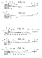
FIG. 17 is a partial cross-sectional view similar toFIG. 12 but showing another example deck obstruction constructed in accordance with the teachings disclosed herein in an unrestrained position. -
FIG. 18 is a partial cross-sectional view similar toFIG. 17 but showing the example deck obstruction ofFIG. 17 in a secured position. -
FIG. 19 is a partial cross-sectional view similar toFIG. 18 but showing the example deck obstruction ofFIG. 17 being blocked by a side wall of a pit. -
FIG. 20 is a partial cross-sectional view similar toFIG. 12 but showing another example deck obstruction constructed in accordance with the teachings disclosed herein in an unrestrained position. -
FIG. 21 is a partial cross-sectional view similar toFIG. 20 but showing the example deck obstruction ofFIG. 20 in a secured position. -
FIG. 22 is a partial cross-sectional view similar toFIG. 12 but showing another example deck obstruction constructed in accordance with the teachings disclosed herein in an unrestrained position. -
FIG. 23 is a partial cross-sectional view similar toFIG. 22 but showing the example deck obstruction ofFIG. 22 in a secured position. -
FIG. 24 is a side view of an example actuating mechanism constructed in accordance with the teachings disclosed herein. -
FIG. 25 is a side view similar toFIG. 24 but showing the example obstruction actuator ofFIG. 24 being pulled up prior to it being rotated. -
FIG. 26 is a side view similar toFIG. 25 but showing the example obstruction actuator ofFIGS. 24 and 25 rotated to place an example dock leveler in a service configuration. -
FIG. 27 is a top view of a cup portion of the example actuating mechanism shown inFIGS. 24 - 26 . -
FIG. 28 is a front view of a first subassembly of the example actuating mechanism shown inFIGS. 24 - 26 . -
FIG. 29 is a top view ofFIG. 28 . -
FIG. 30 is a right side view ofFIG. 28 . -
FIG. 31 is a front view of a second subassembly of the example actuating mechanism shown inFIGS. 24 - 26 . -
FIG. 32 is a top view ofFIG. 31 . -
FIG. 33 is a right side view ofFIG. 31 . -
FIG. 34 is a top view similar toFIG. 8 but showing another example dock leveler constructed in accordance with the teachings disclosed herein. -
FIG. 35 is a cross-sectional view taken along line 35-35 ofFIG. 34 but without showing the dock leveler's deck and lip. -
FIG. 36 is a cross-sectional view similar toFIG. 35 but showing another example actuating mechanism constructed in accordance with the teachings disclosed herein. -
FIG. 37 is a top view similar toFIG. 34 but showing another example mechanical coupling constructed in accordance with the teachings disclosed herein. - The example dock leveler safety supports disclosed herein establish a safe working condition in which to maintain, clean and/or otherwise service dock levelers. To maintain, clean and/or otherwise service a pit area underneath the deck of a dock leveler, some example dock levelers disclosed herein include deck obstructions and/or lip obstructions that can be deployed for securing the dock leveler's deck and/or lip in a raised or extended position for the purpose of providing safe access to the underside of the deck. In some examples, the deck and/or lip obstructions disclosed herein may be actuated by manually lifting and/or rotating a handle via an upper surface of the deck. In some examples, the handle may be recessed within the deck (e.g., below a cross-traffic surface of the deck) when the dock leveler is configured in its normal working configuration and protrudes prominently above the deck (e.g., extends above or past the cross-traffic surface of the deck) when the dock leveler is (e.g., locked-out) in a service configuration for maintenance. In some examples, the deck obstructions extend visibly beyond the sides of the deck to provide, for example, further warning and/or a visible warning that the dock leveler is in the service configuration.
-
FIGS. 1 - 36 show example dock levelers and their various components constructed in accordance with the teachings disclosed herein. Each of the example dock levelers can be configured selectively in a working configuration (e.g.,FIGS. 1 - 3 ,8 ,9 ,11 ,12 ,15 ,17 ,20 ,22 ,24 and34 ) or a service configuration (e.g.,FIGS. 6, 7 ,10 ,13, 14 ,16, 18 ,21, 23 ,26 ,35 and 36 ). The working configuration provides normal operation in transferring cargo between aplatform 10 of aloading dock 12 and a vehicle 14 (truck, trailer, etc.) parked at theloading dock 12. During inspection, cleaning, maintenance and/or other service operations, the service configuration prevents movement of adeck 16 of the dock leveler and provides workers with safe access to the underside of the dock leveler'sdeck 16. - The
deck 16 of the illustrated example has anouter perimeter 15 defined by afront edge 20, arear edge 26, and two lateral edges 25 (FIGS. 8 and 9 ). Thefront edge 20 and therear edge 26 extend in a lateral direction 76 (FIGS. 8 and 9 ), and thelateral edges 25 are generally parallel to each other and substantially perpendicular to thelateral direction 76. Thelateral edges 25 of theexample deck 16 define awidth 35 of thedeck 16. - In some examples, an example dock leveler 18 disclosed herein, when in the working configuration for normal operation, follows the sequence shown in
FIGS. 1 - 3. FIG. 1 shows thevehicle 14 backed up and parked at theloading dock 12 while thefront edge 20 of thedeck 16 of thedock leveler 18 is at a lowered cross-traffic position with an upward facingside 22 of thedeck 16 and the lateral edges 25 being generally flush with theplatform 10.FIG. 2 shows adeck actuator 34 raising thedeck 16 by pivoting it upward about the deck'srear edge 26, andFIG. 2 further shows alip actuator 28 extending alip 30 out from the deck'sfront edge 20. This allowsdeck 16 andlip 30 to be subsequently lowered upon acargo bed 32 of thevehicle 14, as shown inFIG. 3 . Withlip 30 resting atop thecargo bed 32, thedeck 16 and thelip 30 provide a bridge across which cargo can be transferred betweenvehicle 14 andplatform 10 for loading/unloading operations. - The
deck actuator 34 is schematically illustrated as an arrow to represent all types of known deck actuators. The term, "deck actuator" refers to any structure capable of forcing or moving a deck up and/or down (e.g., pivoting and/or translating up or down). Examples of a deck actuator include, but are not limited to, a hydraulic cylinder, a pneumatic cylinder, a helical spring, a pneumatic spring, a hydraulic motor, a pneumatic motor, an electric motor (e.g., a linear motor), an inflatable diaphragm, and/or various combinations thereof. - Likewise, the
lip actuator 28 is schematically illustrated as an arrow to represent all types of known lip actuators. The term, "lip actuator" refers to any structure capable of extending and/or retracting a lip relative to a deck. The lip's extension or retraction can be by way of pivoting and/or translating. Examples of a lip actuator include, but are not limited to, a hydraulic cylinder, a pneumatic cylinder, a helical spring, a pneumatic spring, a hydraulic motor, a pneumatic motor, an electric motor (e.g., a linear motor), an inflatable diaphragm, and/or various combinations thereof. - In the service configuration, the
dock leveler 18 of the illustrated example is operated in the examples shown inFIGS. 4 - 7 , whereFIGS. 6 and 7 are slightly different views of the.FIG. 4 shows thedeck actuator 34 raising thedeck 16 and thelip actuator 28 extending thelip 30. Next, thedeck 16 alone, or in combination with thelip 30, is held in a generally elevated position by abackup support mechanism 36. In the illustrated example, thebackup support mechanism 36 includes a deck obstruction 38 (FIG. 7 ) for supporting thedeck 16, alip obstruction 40 for supporting thelip 30, and anobstruction actuator 24 for extending and retracting theobstructions backup support mechanism 36 can support both thedeck 16 and thelip 30 in the raised or the extended positions without having to rely on the power of theactuators - After extending the
obstructions obstruction actuator 24 as indicated byarrows 42 and 44 (FIGS. 4 and 5 ), thelip 30 can tilt down and find support against thelip obstruction 40, as shown inFIG. 5 , and thedeck 16 can descend until thedeck obstruction 38 engagesplatform 10 to support the weight of thedeck 16, as shown inFIGS. 6 and 7 . Once thedeck obstruction 38 supports thedeck 16 and thelip obstruction 40 supports thelip 30, as shown inFIGS. 6 and 7 , thebackup support mechanism 36 maintains thedock leveler 18 in a service configuration while theactuators - Various mechanisms can be used for deploying the
obstructions FIGS. 1 - 14 , theobstruction actuator 24 is in the form of a manually operated handle that is mechanically coupled to turn a drivingmember 46 about afirst axis 48. Details of mechanically coupling thehandle 24 to the drivingmember 46 will be disclosed below in connection withFIGS. 24 - 33 . - Returning to
FIGS. 1 - 14 , in some examples, twoconnectors 50 connect or couple the drivingmember 46 to thedeck obstructions 38, and athird connector 52 connects the drivingmember 46 to thelip obstruction 40. In the example illustrated inFIGS. 1 - 14 , theconnectors member 46 and an opposite end coupled to therespective obstruction obstruction actuator 24, when rotating the drivingmember 46 in a first direction 54 (e.g., clockwise 54 in the orientation ofFIG. 10 ) from the position ofFIG. 8 to that ofFIG. 10 , forces theconnectors obstructions member 46. In examples that include the twodeck obstructions 38, as shown inFIGS. 8 and 10 , thedeck obstructions 38 span adeck obstruction distance 56 that is greater when thedock leveler 18 is in the service configuration than whendock leveler 18 is in the working configuration. A sleeve 58 (FIGS. 12 and 14 ) welded and/or otherwise rigidly attached or coupled to aside plate 60 or other structural member of thedeck 16 helps guide the linear movement of thedeck obstruction 38. Apin 62 pivotally connects thelip obstruction 40 to thedeck 16 to help guide the rotational movement of thelip obstruction 40. Since theconnectors member 46 rotates, thepins connectors respective obstructions -
FIGS. 15 - 23 show other example deck obstructions, lip obstructions and connectors constructed in accordance with the teachings disclosed herein. The example shown inFIGS. 15 and 16 is similar to that shown inFIGS. 1 -14 . However, instead of thedeck obstruction 38 resting atopplatform 10 when thedeck obstruction 38 is in the secured position, thedeck obstruction 38 extends into a cavity 68 (e.g., a hole, slot, etc.) to secure thedeck 16, as shown inFIG. 16 . In the illustrated example, thecavity 68 is in aside wall 70 of apit 72 defined by theplatform 10. Thepit 72 has a pit width 74 (FIGS. 8 and 9 ) as measured in alateral direction 76. Referring toFIGS. 15 and 16 , retracting thedeck obstruction 38 out from within thecavity 68 moves thedeck obstruction 38 to an unrestrained position and configures thedock leveler 18 in a working configuration, as shown inFIG. 16 . -
FIGS. 17 - 19 show anexample connector 50a constructed in accordance with the teachings disclosed herein that is spring-loaded, which allows theconnector 50a to compress in length when the drivingmember 46 urges theconnector 50a to extend while thedeck obstruction 38 and/or the lip obstruction is unable to do so because thedeck obstruction 38 is neither above theplatform 10 nor aligned with thecavity 68, as shown inFIG. 19 . Theconnector 50a is shown compressed inFIG. 19 , so upon subsequently raisingdeck 16 to the position shown inFIG. 18 , theconnector 50a will automatically extend thedeck obstruction 38 out over theplatform 10. - The spring-loaded feature can be particularly useful in certain methods of dock leveler operation. For instance, one example sequence of operation is as follows. First, a dock worker approaches the
dock leveler 18 when thedeck 16 is in the lowered cross-traffic position, as shown inFIGS. 1 ,8 and 9 . Second, the worker manually manipulates the obstruction actuator 24 (seearrows FIGS. 4 and 5 ) to extend thedeck obstruction 38 to the intermediate position shown inFIG. 19. FIG. 19 shows thespring 82 urging thedeck obstruction 38 laterally against theside wall 70 of thepit 72. Third, the worker uses a suitable known dock leveler controller (e.g., a PLC, computer, electromechanical relays, push buttons, etc.) to activate thedeck actuator 34 so thatdeck actuator 34 raises thedeck 16 while thespring 82 continues urging thedeck obstruction 38 laterally outward. Fourth, when thedeck obstruction 38 rises above theplatform 10, as shown inFIGS. 7 ,18 or higher; thespring 82 moves thedeck obstruction 38 laterally outward beyond the side wall 70 (seeFIG. 18 ), as thedeck obstruction 38 is no longer obstructed by theside wall 70. Fifth, with thedeck obstruction 38 now extending out over theplatform 10, the worker uses the controller to activate thedeck actuator 34 in a way that lowers thedeck 16 until thedeck obstruction 38 is resting upon theplatform 10 and supporting at least some of the weight of thedeck 16, as shown inFIGS. 7 ,10 and18 . At this point in the operation, thedock leveler 18 is in the service configuration. - With deck obstructions or actuating mechanisms that are spring loaded (e.g.,
FIGS. 17 - 21 ,36 and37 ), returning thedock leveler 18 back to the working configuring can be as follows. First, the dock worker approaches thedock leveler 18 while thedeck obstructions 38 are supporting at least some of the weight of thedeck 16, e.g.,FIGS. 7 ,10 and18 . Second, the worker manually manipulates the obstruction actuator 24 (e.g., in a direction opposite to that ofarrows FIGS. 4 and 5 ) so that thespring 82 urges thedeck obstruction 38 to retract. In some examples, however, thespring 82 is unable to retract thedeck obstruction 38 due to substantial frictional forces developed by the weight of thedeck 16 pressing thedeck obstruction 38 down against theplatform 10. Consequently, although thespring 82 urges thedeck obstruction 38 to retract, thedeck obstruction 38 does not retract until the worker uses the controller to activate thedeck actuator 34 to raise thedeck 16 slightly and thus lift thedeck obstruction 38 off of theplatform 10. Third, once thedeck obstruction 38 lifts off of theplatform 10, thespring 82 retracts thedeck obstruction 38 laterally inward to the position shown inFIG. 17 . Fourth, after thedeck obstruction 38 is no longer extending laterally outward beyond theside wall 70 of thepit 72, the worker uses the controller to activate thedeck actuator 34 in a way that lowers thedeck 16 and lowers thedeck obstruction 38 below theplatform 10, as shown inFIGS. 8 and 9 . At this point, thedock leveler 18 is back to the working configuration. - The actual construction of the
example connector 50a may vary. In the example illustrated inFIGS. 17 - 19 , theconnector 50a comprises arod 78 that fits telescopically within a sleeve androd member 80. Acompression spring 82 is held in compression between acollar 84 on therod 78 and anaxial end 86 of themember 80. Apin 88 extending radially from therod 78 slides within aslot 90 in themember 80 to limit the axial travel of therod 78 in themember 80. -
FIGS. 20 and 21 show an example spring-loadeddeck obstruction 92 and aconnector 50b in the form of a compliant elongate member. The term, "compliant elongate member" refers to any element having a length that is at least five times greater than its height and width, where the element when alone and unrestrained is sufficiently flexible to be coiled in at least a single 360-degree loop and subsequently straightened without appreciable permanent deformation (e.g., without plastically deforming the elongate member). Examples of a compliant elongate member include, but are not limited to, a chain, a cable, a cord, a strap, a spring, a wire, a rope, and/or a belt. In this example, acompression spring 94 urges thedeck obstruction 92 toward its secured position (FIG. 21 ). In the unrestrained position (FIG. 20 ), tension in theconnector 50b pulls thedeck obstruction 92 within thedeck 16 and away from theplatform 10. In the secured position (FIG. 21 ), the drivingmember 46 releases the tension in theconnector 50b, thereby allowing thespring 94 to move, slide and/or push thedeck obstruction 92 out over theplatform 10, as shown inFIG. 21 . -
FIGS. 22 and 23 show anexample deck obstruction 96 that uses gravity in moving from the unrestrained position (FIG. 22 ) to the secured position (FIG. 23 ). Thedeck obstruction 96 of the illustrated example passes through anopening 98 in thedeck 16 by pivoting about apin 100 attached to thedeck 16. Aconnector 50c in the form of a compliant elongate member attached to the drivingmember 46 is used for moving, sliding and/or pulling thedeck obstruction 96 from the secured position back to the unrestrained position. - Although various mechanisms can be used for moving the deck and lip actuators disclosed herein,
FIGS. 24 - 33 show one example of anactuating mechanism 102 constructed in accordance with the teachings disclosed herein. Theactuating mechanism 102 not only provides means for rotating the drivingmember 46 to move the deck and lip actuators, but theactuating mechanism 102 also ensures that the obstruction actuator 24 (in the form of a manually operated handle) protrudes prominently above the deck's upwardly facing side 22 (e.g., a cross-traffic surface of the deck 16) when thedock leveler 18 is in the service configuration. Theobstruction actuator 24 protruding above thedeck 16 provides a visible signal to personnel in the area that thedock leveler 18 is in the service configuration. Theobstruction actuator 24 being generally flush or recessed below the deck's upwardly facing side 22 (e.g., the cross-traffic surface of the deck 16) indicates thatdock leveler 18 is in the working configuration with thedeck obstruction 38 being in the unrestrained position and/or thelip obstruction 40 being in the release position. - To deploy the
obstructions dock leveler 18 is in the service configuration, some examples ofactuating mechanism 102 include the obstruction actuator 24 (e.g., a handle), the drivingmember 46, acompression spring 104, afirst subassembly 106, asecond subassembly 108, and a recessedcup 110 to receive theobstruction actuator 24. Thefirst subassembly 106 of the illustrated example includes theobstruction actuator 24, afirst slide plate 112, alower plate 114, and astop pin 116. Thesecond subassembly 108 of the illustrated example includes anupper plate 118, asecond slide plate 120 and drivingmember 46. In some examples, screws 122 and/or other suitable fasteners are used in assembling thesubassemblies screws 122 also enable the twosubassemblies spring 104 installed between the upper andlower plates cup 110 is welded to thedeck 16 with the base of thecup 110 being interposed between thestop pin 116 and theupper plate 118. - The
obstruction actuator 24, thefirst slide plate 112, thelower plate 114, and thestop pin 116 of the illustrated example rotate about theaxis 48 and slide axially as a unit relative to thesecond subassembly 108. Theslots respective slide plates subassemblies spring 104 acting between the upper andlower plates subassemblies obstruction actuator 24. When theobstruction actuator 24 is in the position shown inFIG. 24 (e.g., the working configuration), thefirst slide plate 112 is free to slide through aslot 128 in thecup 110 and through aslot 130 in the upper plate 118.However, thestop pin 116 engaging aninside bottom surface 132 of thecup 110 limits the distance in which thespring 104 can move theobstruction actuator 24 down toward thesecond subassembly 108. In some examples, thestop pin 116 settles within a detent on the cup'sbottom surface 132. - When the
obstruction actuator 24 is in the position shown inFIG. 26 (e.g., the service configuration), thenotches 134 in thefirst slide plate 112 are at an elevation that provides clearance with thecup 110 and theupper plate 118 so thatfirst slide plate 112 can be rotated 90 degrees from the position shown inFIG. 25 to the position ofFIG. 26 . Once rotated, as shown inFIG. 26 , the upper edges of thenotches 134 engage the cup's insidebottom surface 132, thereby limiting the distance in which thespring 104 can move theobstruction actuator 24 back down into the cup 110.Thus theobstruction actuator 24 protrudes above the deck 16 (e.g., above a cross-traffic surface of the deck 16) when thedock leveler 18 is in the service configuration. - In some examples, to change the
dock leveler 18 from the working configuration to the service configuration, theobstruction actuator 24 is first manually lifted (e.g., in the direction ofarrow 42 inFIG. 4 ) from the position ofFIG. 24 to that ofFIG. 25 , and then theobstruction actuator 24 is manually rotated (arrow 44 inFIG. 5 ) between the position ofFIG. 25 to that ofFIG. 26 . The rotation of theobstruction actuator 24 from the position ofFIG. 25 to that ofFIG. 26 rotates the drivingmember 46, which moves thedeck obstruction 38 from the unrestrained position to the secured position and/or moves thelip obstruction 40 from the release position to the support position, thereby reconfiguring thedock leveler 18 from the working configuration to the service configuration. - In some examples it might be beneficial to have the
obstruction actuator 24 closer to the deck'srear edge 26 and have a drivingmember 46 farther or spaced away from the drivingmember 46 adjacent thehandle 24, as shown inFIGS. 34 and 35 . Theobstruction actuator 24 might be more accessible to dock workers on theplatform 10 if theobstruction actuator 24 is closer to the deck'srear edge 26. Having a drivingmember 46 and the associated thedeck obstruction 38 farther or spaced away from the deck'srear edge 26 places thedeck obstruction 38 at a more mechanically advanced position that reduces the vertical load and/or shear strain on thedeck obstruction 38 when thedeck obstruction 38 is in the service condition. Also, thedeck obstruction 38 being farther forward (e.g., away from the rear edge 26) provides thedeck obstruction 38 with more mounting location options because the more forward thedeck obstruction 38 is, the more of thedeck 16 is exposed above theplatform 10. - Therefore, in some examples, the
obstruction actuator 24 and the drivingmember 46 are installed to rotate about afirst axis 48, and asecond driving member 46 operatively coupled to the deck obstruction 38 (and/or lip obstruction 40) is installed to rotate about asecond axis 136 that is radially and/or laterally offset tofirst axis 48. In the illustrated example, thesecond axis 136 is parallel relative to thefirst axis 48. However, in other examples, thesecond axis 136 may be non-parallel relative to thefirst axis 48. A mechanical coupling 138 (e.g., linkage system, drive chain, cogged belt, etc.) couples the first drivingmember 46 and the second drivingmember 46 so that one driving member rotates the other (e.g., simultaneously). - In addition or as an alternative to the spring-loaded features shown in
FIGS. 17 - 21 , some example actuating mechanisms disclosed herein include one ormore springs 140 that couple and provide spring-loaded rotational slip between the first andsecond driving members 46, as shown inFIG. 36 . If the pit'sside wall 70 or something else blocks the extension of thedeck obstruction 38 and/or thelip obstruction 40, thespring 140 allows theobstructions 38 and/or 40 to hold thelower driving member 46 stationary even though the upper drivingmember 46 rotates (e.g., about the axis 48). If thedeck obstruction 38 and thelip obstruction 40 are free to extend, thespring 140 transmits the rotational torque from the first upper drivingmember 46 to the second lower drivingmember 46 so that the first drivingmember 46 rotates the second driving member 46.Thus theobstructions second driving members 46 engage each other to limit the relative rotational slip between the first andsecond driving members 46. - In some examples, to more clearly indicate when the
dock leveler 18 is in the service configuration, thedock leveler 18 includes a light that is controlled to illuminate theobstruction actuator 24 when theobstruction actuator 24 is protruding above thedeck 16. Thus, some examples of theobstruction actuator 24 are illuminated more when thedock leveler 18 is in the service configuration than when thedock leveler 18 is in the working configuration. Such a light can be installed in various locations, examples of which include, but are not limited to, embedded within or attached to theobstruction actuator 24, installed within thecup 110, and/or installed underneath thedeck 16 and projecting light upward toward theobstruction actuator 24. In some examples, the light flashes so it is more noticeable. - For clarity, it should be noted that the term, "proximate" means within approximately six inches. The term, "obstruction" refers to any member that physically blocks the movement of another member. The obstruction actuator being manually accessible from above the deck means that a person while standing on the deck's upwardly facing side 22 (e.g., a cross-traffic surface) can manually and fully operate the obstruction actuator by hand. The term, "upwardly facing side" or "cross-traffic surface" refers to the surface upon which material handling equipment and other traffic normally travel. Also, of the various example dock leveler component parts and features, such parts and features are interchangeable such that parts and features of one disclosed example can be added or substituted for parts and features of another example dock leveler. In some examples, the lip actuator 28 (
FIG. 4 ) and thelip obstruction 40 share one or more of the same components. For instance, in some examples, thelip obstruction 40 is used for extending and retractinglip 30 when thedock leveler 18 is in the working configuration during normal operation. In some examples, themechanical coupling 138, ofFIG. 35 , includes a spring-loaded feature to provide the connection between the drivingmembers 46 with resilient slip that accommodates theobstructions 38 and/or 40 becoming blocked in manners similar to those described with reference toFIGS. 17 - 19 and36 .FIG. 37 , for example, shows a mechanical coupling 138' in the form of a tension spring. - While some example dock levelers have just one
deck obstruction 38, other example dock levelers disclosed herein have two ormore deck obstructions 38 to provide thedeck 16 with more balanced support. Although some example deck obstructions or lip obstructions are actuated manually by lifting and turning a handle, other example deck obstructions or lip obstructions disclosed herein are power operated via, for example, a actuator. Examples of powered actuators include, but are not limited to, a hydraulic cylinder, a pneumatic cylinder, a hydraulic motor, a pneumatic motor, an electric motor (e.g., a linear motor), an inflatable diaphragm, and/or various combinations thereof. - Some example dock levelers include a padlock or other type of lock that prevents unauthorized individuals from moving the
obstruction actuator 24 in a way that would shift and/or move thedock leveler 18 back to its working configuration. There are various examples of such lockout means, and some examples of them include, but are not limited to, a removable padlock on thedeck obstruction 38, other types of locks on thedeck obstruction 38, a locking device or mechanism (e.g., a padlock) that selectively permits or prevents the rotation of the drivingmember 46, a locking device or mechanism that selectively permits or prevents the movement of theconnector 50, a locking device or mechanism that selectively permits or prevents the movement of theobstruction actuator 24, and a locking device or mechanism that selectively permits or prevents the movement of theactuating mechanism 102, etc. - At least some of the aforementioned examples include one or more features and/or benefits including, but not limited to, the following:
- In some examples, an example dock leveler disclosed herein is installable at a loading dock having a platform, the platform defining a pit having a pit width as measured in a lateral direction, the dock leveler having a deck having an outer perimeter defined by a front edge, a rear edge, a first lateral edge and a second lateral edge, the rear edge being proximate the platform and the front edge being movable relative to the platform between a raised position and a lowered cross-traffic position when the dock leveler is in a working configuration, the first lateral edge and the second lateral edge being proximate the platform when the deck is in the lowered cross-traffic position, the deck residing at least partially in the pit when the front edge of the deck is in the lowered cross-traffic position, the front edge being above at least one of the lowered cross-traffic position or the raised position and inhibited from descending toward the lowered cross-traffic position when the dock leveler is in a service configuration. The dock leveler, in some examples having a first deck obstruction movable relative to the deck between a secured position and an unrestrained position, the first deck obstruction in the secured position configures the dock leveler in the service configuration and the first deck obstruction in the unrestrained position configures the dock leveler in the working configuration, where the first deck obstruction extends farther beyond the outer perimeter of the deck when the first deck obstruction is in the secured position than when the first deck obstruction is in the unrestrained position, and an obstruction actuator operatively coupled to the first deck obstruction to move the first deck obstruction between the secured position and the unrestrained position.
- In some examples, a first deck obstruction protrudes above a surface of a platform when the first deck obstruction is in the secured position.
- In some examples, a first deck obstruction includes an elongate bar that extends greater horizontally than vertically.
- In some examples, a compliant elongate member coupled to the first deck obstruction.
- In some examples, a spring is coupled to the first deck obstruction.
- In some examples, a first deck obstruction and a second deck obstruction protrude away from each other to span an overall deck obstruction distance that varies depending on whether the dock leveler is in a working configuration or in a service configuration, where the overall deck obstruction distance is greater than the pit width when the dock leveler is in the service configuration, and the overall deck obstruction distance is less than the pit width when the dock leveler is in the working configuration.
- In some examples, an obstruction actuator is accessible from above the deck.
- In some examples, a dock leveler is installable at a loading dock having a platform, the dock leveler having a deck, a deck actuator, a first deck obstruction, and an obstruction actuator.
- In some examples, the deck has a front edge, a rear edge proximate the platform, a first lateral edge extending between the front edge and the rear edge, and a second lateral edge extending between the front edge and the rear edge, where the front edge is movable relative to the platform selectively between a raised position and a lowered cross-traffic position when the dock leveler is in a working configuration, and where the first lateral edge and the second lateral edge are proximate the platform when the deck is in the lowered cross-traffic position and the front edge is positioned above the lowered cross-traffic position and inhibited from descending toward the lowered cross-traffic position when the dock leveler is in a service configuration. In some such examples, a deck actuator is configured to move the front edge of the deck between the raised position and the lowered cross-traffic position when the dock leveler is in the working configuration. In some such examples, a lip is proximate the front edge of the deck and is movable relative to the deck selectively between an extended position and a retracted position while the dock leveler is in the working configuration. In some such examples, a first deck obstruction is movable relative to the deck actuator and the first deck obstruction is movable relative to the deck between the secured position and the unrestrained position, where the first deck obstruction in the secured position configures the dock leveler in the service configuration and the first deck obstruction in the unrestrained position configures the dock leveler in the working configuration. In some such examples, the first deck obstruction in the secured position is to physically block downward movement of a deck toward a lowered cross-traffic position, where the first deck obstruction in the unrestrained position permits downward movement of the deck toward the lowered cross-traffic position. In some examples, an obstruction actuator is operatively coupled to the first deck obstruction to move the first deck obstruction between the secured position and the unrestrained position, where the obstruction actuator is accessible from an upper surface of the deck.
- In some examples, a lip obstruction is selectively movable relative to a first deck obstruction between a support position and a release position, where the lip obstruction in the support position prevents the lip from moving to the retracted position and the lip obstruction in the release position permits the lip to move to the retracted position. In some such examples, the obstruction actuator is operatively coupled to the lip obstruction to move the lip obstruction between the support position and the release position.
- In some examples, the obstruction actuator is a manually operated handle assessable via the upper surface of the deck.
- In some examples, a manually operated handle protrudes above the upper surface of the deck when the dock leveler is in the service configuration and the manually operated handle is retracted or recessed below the upper surface of the deck when the dock leveler is in the working configuration.
- In some examples, an obstruction actuator is more illuminated when the dock leveler is in the service configuration than when the dock leveler is in the working configuration.
- In some examples, a platform defines a pit in which the deck resides when the front edge of the deck is in the lowered cross-traffic position when the deck is in the working configuration, the first deck obstruction to protrude horizontally beyond a perimeter of the pit defined inner surfaces of walls defining the pit when the first deck obstruction is in the secured position, and the first deck obstruction is retracted within the inner perimeter defined by the walls of the pit when the first deck obstruction is in the unrestrained position.
- In some examples, the first deck obstruction protrudes out over the platform when the dock leveler is in the service configuration.
- In some examples, the first deck obstruction includes an elongate bar coupled to the obstruction actuator.
- In some examples, a compliant elongate member is coupled between the obstruction actuator and the first deck obstruction.
- In some examples, the pit has a pit width as measured in a direction generally parallel to the rear edge of the deck, and the dock leveler further comprises a second deck obstruction, the first deck obstruction and the second deck obstruction protruding away from each other to span an overall deck obstruction distance that varies depending on whether the dock leveler is in the working configuration or in the service configuration, the overall deck obstruction distance being greater than the pit width when the dock leveler is in the service configuration, and the overall deck obstruction distance being less than the pit width when the dock leveler is in the working configuration.
- In some examples, a spring is coupled to the first deck obstruction, where the spring urges the first deck obstruction toward the secured position.
- In some examples, the first deck obstruction is urged toward the secured position by gravitational force.
- In some examples, an actuator mechanism includes the obstruction actuator, a first driving member, and a second driving member, where the obstruction actuator is configured to rotate the first driving member, the first driving member is configured to rotate the second driving member, and the second driving member is configured to move the first deck obstruction between the secured position and the unrestrained position. In some such examples, a first axis about which the obstruction actuator and the first driving member rotate and a second axis about which the second driving member rotates are offset.
- In some examples, a dock leveler installable at a loading dock having a platform includes a deck movable relative to a platform between a raised position and a lowered cross-traffic position when the dock leveler is in a working configuration, where the deck is held above at least one of the lowered cross-traffic position or the raised position and inhibited from descending toward the lowered cross-traffic position when the dock leveler is in the service configuration. In some such examples, a first deck obstruction is movable relative to the deck between a secured position and an unrestrained position, where the first deck obstruction in the secured position configures the dock leveler in the service configuration and the first deck obstruction in the unrestrained position configures the dock leveler in the working configuration, and where the first deck obstruction in the secured position blocks movement of the deck toward the lowered cross-traffic position and the first deck obstruction in the unrestrained position permits movement of the deck toward the lowered cross-traffic position. In some such examples, a handle is operatively coupled to the first deck obstruction to move the first deck obstruction between the secured position and the unrestrained position, the handle is recessed relative to a cross-traffic surface of the deck when the dock leveler is in the working configuration, and the handle protrudes above the cross-traffic surface of the deck when the dock leveler is in the service configuration.
- In some examples, a lip is proximate a front edge of the deck and is movable relative to the deck between an extended position and a retracted position when the dock leveler is in the working configuration. In some such examples, a lip obstruction is movable relative to the first deck obstruction between a support position and a release position, where the lip obstruction in the support position prevents the lip from moving to the retracted position and the lip obstruction in the release position permits movement of the lip toward the retracted position, and the handle is operatively coupled to the lip obstruction to move the lip obstruction between the support position and the release position.
- In some examples, the handle is more illuminated when the dock leveler is in the service configuration than when the dock leveler is in the working configuration.
- In some examples, the platform defines a pit in which the deck resides when the deck is in the lowered cross-traffic position, where the first deck obstruction protrudes horizontally beyond the pit when the first deck obstruction is in the secured position and the first deck obstruction retracts within the pit when the first deck obstruction is in the unrestrained position.
- In some examples, the first deck obstruction protrudes out over the platform when the dock leveler is in the service configuration.
- In some examples, the first deck obstruction engages a surface of the platform when the dock leveler is in the service configuration.
- In some examples, a pit has a pit width as measured in a direction generally parallel to a rear edge of the deck opposite a front edge of the deck, where the dock leveler further includes a second deck obstruction, the first deck obstruction and the second deck obstruction to protrude away from each other to span an overall deck obstruction distance that varies depending on whether the dock leveler is in the working configuration or in the service configuration, the overall deck obstruction distance being greater than the pit width when the dock leveler is in the service configuration and the overall deck obstruction distance being less than the pit width when the dock leveler is in the working configuration.
- In some examples, an actuator mechanism includes the handle, a first driving member and a second driving member, the handle is configured to rotate the first driving member, the first driving member is configured to rotate the second driving member, and the second driving member is configured to move the first deck obstruction between the secured position and the unrestrained position, where a first axis about which the handle and the first driving member rotate is offset relative to a second axis about which the second driving member rotates.
- In some examples, a dock leveler method for operating a dock leveler having at least one of a deck installed within a pit and the pit being defined by a platform that faces upward and a side wall that faces in a lateral direction, the dock leveler method including urging, via a spring, the deck obstruction laterally against the side wall of the pit; raising the deck while the spring urges the deck obstruction laterally against the side wall of the pit; moving the deck obstruction above the platform via the deck; in response to the deck obstruction rising above the platform, the moving, via the spring, the deck obstruction laterally outward beyond the side wall of the pit; after the deck obstruction protrudes laterally outward beyond the side wall of the pit, descending the deck and thereby lowering the deck obstruction onto the platform; and supporting at least a portion of the deck's weight via engagement between the deck obstruction and the platform.
- In some examples, a method includes supporting the obstruction actuator via the deck; and manually manipulating the obstruction actuator, wherein the spring urging the deck obstruction laterally against the side wall of the pit is performed in response to manually manipulating the obstruction actuator.
- In some examples, a method includes after the deck obstruction is supporting at least a portion of the deck's weight, raising the deck to lift the deck obstruction off the platform; in response to raising the deck to lift the deck obstruction off a surface of the platform, moving, via the spring, the deck obstruction laterally inward such that the deck obstruction no longer extends laterally outward beyond the side wall of the pit; and after the deck obstruction is no longer extending laterally outward beyond the side wall of the pit, descending the deck and thereby lowering the deck obstruction below the surface of the platform.
- In some examples, a method includes supporting the obstruction actuator via the deck; and manually manipulating the obstruction actuator, wherein the spring moving the deck obstruction laterally inward is performed as a result of both manually manipulating the obstruction actuator and raising the deck to lift the deck obstruction off the surface of the platform.
- In some examples, a dock leveler installable at a loading dock having a platform comprises a deck movable relative to a platform between a raised position and a lowered cross-traffic position when the dock leveler is in a working configuration, the deck being held above at least one of the lowered cross-traffic position or the raised position and inhibited from descending toward the lowered cross-traffic position when the dock leveler is in a service configuration; a first deck obstruction being movable relative to the deck between a secured position and an unrestrained position, the first deck obstruction in the secured position configures the dock leveler in the service configuration, the first deck obstruction in the unrestrained position configures the dock leveler in the working configuration, the first deck obstruction in the secured position to block movement of the deck toward the lowered cross-traffic position, the first deck obstruction in the unrestrained position to permit movement of the deck toward the lowered cross-traffic position; and a handle operatively coupled to the first deck obstruction to move the first deck obstruction between the secured position and the unrestrained position, the handle being recessed relative to a cross-traffic surface of the deck when the dock leveler is in the working configuration, and the handle to protrude above the cross-traffic surface of the deck when the dock leveler is in the service configuration.
- In some examples, the dock leveler further comprises a lip proximate a front edge of the deck and being movable relative to the deck between an extended position and a retracted position when the dock leveler is in the working configuration; and a lip obstruction being movable relative to the first deck obstruction between a support position and a release position, the lip obstruction in the support position to prevent the lip from moving to the retracted position, the lip obstruction in the release position to permit movement of the lip toward the retracted position, the handle being operatively coupled to the lip obstruction to move the lip obstruction between the support position and the release position.
- In some examples of the dock leveler, the handle is more illuminated when the dock leveler is in the service configuration than when the dock leveler is in the working configuration.
- In some examples of the dock leveler, the platform defines a pit in which the deck resides when the deck is in the lowered cross-traffic position, the first deck obstruction to protrude horizontally beyond the pit when the first deck obstruction is in the secured position, and the first deck obstruction to be retracted within the pit when the first deck obstruction is in the unrestrained position.
- In some examples of the dock leveler, the first deck obstruction protrudes out over the platform when the dock leveler is in the service configuration.
- In some examples of the dock leveler, the platform defines a pit, the pit having a pit width as measured in a direction generally parallel to a rear edge of the deck opposite a front edge of the deck, the dock leveler further comprises a second deck obstruction, the first deck obstruction and the second deck obstruction to protrude away from each other to span an overall deck obstruction distance that varies depending on whether the dock leveler is in the working configuration or in the service configuration, the overall deck obstruction distance being greater than the pit width when the dock leveler is in the service configuration and the overall deck obstruction distance being less than the pit width when the dock leveler is in the working configuration.
- In some examples the dock leveler further comprises an actuator mechanism that includes the handle, a first driving member and a second driving member, the handle being configured to rotate the first driving member, the first driving member being configured to rotate the second driving member, and the second driving member being configured to move the first deck obstruction between the secured position and the unrestrained position; a first axis about which the handle and the first driving member rotate; and a second axis about which the second driving member rotates, the first axis being offset to the second axis.
- In some examples, a dock leveler method for operating a dock leveler, the dock leveler method involving use of at least one of a deck installed within a pit the pit being defined by a platform that faces upward and a side wall that faces in a lateral direction, the dock leveler method comprises: urging, via a spring, a deck obstruction laterally against the side wall of the pit; raising the deck while the spring urges the deck obstruction laterally against the side wall of the pit; moving the deck obstruction above the platform via the deck; in response to the deck obstruction rising above the platform, the moving, via the spring, the deck obstruction laterally outward beyond the side wall of the pit; after the deck obstruction protrudes laterally outward beyond the side wall of the pit, descending the deck and thereby lowering the deck obstruction onto the platform; and supporting at least a portion of the deck's weight via engagement between the deck obstruction and the platform.
- In some examples, the dock leveler method further comprises supporting an obstruction actuator via the deck; and manually manipulating the obstruction actuator, wherein the spring urging the deck obstruction laterally against the side wall of the pit is performed in response to manually manipulating the obstruction actuator.
- In some examples, the dock leveler method further comprises: after the deck obstruction is supporting at least a portion of the deck's weight, raising the deck to lift the deck obstruction off the platform; in response to raising the deck to lift the deck obstruction off a surface of the platform, moving, via the spring, the deck obstruction laterally inward such that the deck obstruction no longer extends laterally outward beyond the side wall of the pit; and after the deck obstruction is no longer extending laterally outward beyond the side wall of the pit, descending the deck and thereby lowering the deck obstruction below the surface of the platform.
- In some examples, the dock leveler method further comprises supporting the obstruction actuator via the deck; and manually manipulating the obstruction actuator, wherein the spring moving the deck obstruction laterally inward is performed as a result of both manually manipulating the obstruction actuator and raising the deck to lift the deck obstruction off the surface of the platform.
- Although certain example methods, apparatus and articles of manufacture have been described herein, the scope of the coverage of this patent is not limited thereto. On the contrary, this patent covers all methods, apparatus and articles of manufacture fairly falling within the scope of the appended claims either literally or under the doctrine of equivalents.
Claims (20)
- A dock leveler installable at a loading dock having a platform, the platform defining a pit having a pit width as measured in a lateral direction, the dock leveler comprising:a deck having an outer perimeter defined by a front edge, a rear edge, a first lateral edge and a second lateral edge, the rear edge being proximate the platform and the front edge being movable relative to the platform between a raised position and a lowered cross-traffic position when the dock leveler is in a working configuration, the first lateral edge and the second lateral edge being proximate the platform when the deck is in the lowered cross-traffic position, the deck residing at least partially in the pit when the front edge of the deck is in the lowered cross-traffic position, the front edge being above at least one of the lowered cross-traffic position or the raised position and inhibited from descending toward the lowered cross-traffic position when the dock leveler is in a service configuration;a first deck obstruction being movable relative to the deck between a secured position and an unrestrained position, the first deck obstruction in the secured position configures the dock leveler in the service configuration, the first deck obstruction in the unrestrained position configures the dock leveler in the working configuration, the first deck obstruction to extend farther beyond the outer perimeter of the deck when the first deck obstruction is in the secured position than when the first deck obstruction is in the unrestrained position; andan obstruction actuator operatively coupled to the first deck obstruction to move the first deck obstruction between the secured position and the unrestrained position.
- The dock leveler of claim 1, wherein the first deck obstruction protrudes above a surface of the platform when the first deck obstruction is in the secured position.
- The dock leveler of claim 1, wherein the first deck obstruction includes an elongate bar that extends greater horizontally than vertically.
- The dock leveler of claim 1, further comprising a compliant elongate member coupled to the first deck obstruction.
- The dock leveler of claim 1, further comprising a spring coupled to the first deck obstruction.
- The dock leveler of claim 1 further comprising a second deck obstruction, the first deck obstruction and the second deck obstruction protruding away from each other to span an overall deck obstruction distance that varies depending on whether the dock leveler is in the working configuration or in the service configuration, the overall deck obstruction distance being greater than the pit width when the dock leveler is in the service configuration, and the overall deck obstruction distance being less than the pit width when the dock leveler is in the working configuration.
- The dock leveler of claim 1, wherein the obstruction actuator is accessible from a cross-traffic surface of the deck.
- A dock leveler installable at a loading dock having a platform, the dock leveler comprising:a deck having a front edge, a rear edge proximate the platform, a first lateral edge extending between the front edge and the rear edge, and a second lateral edge extending between the front edge and the rear edge, the front edge being movable relative to the platform selectively between a raised position and a lowered cross-traffic position when the dock leveler is in a working configuration, the first lateral edge and the second lateral edge being proximate the platform when the deck is in the lowered cross-traffic position, the front edge being positioned above the lowered cross-traffic position and inhibited from descending toward the lowered cross-traffic position when the dock leveler is in a service configuration;a deck actuator configured to move the front edge of the deck between the raised position and the lowered cross-traffic position when the dock leveler is in the working configuration;a lip proximate the front edge of the deck and being movable relative to the deck between an extended position and a retracted position when the dock leveler is in the working configuration;a first deck obstruction movable relative to deck actuator, the first deck obstruction being further movable relative to the deck between a secured position and an unrestrained position, the first deck obstruction in the secured position configures the dock leveler in the service configuration, the first deck obstruction in the unrestrained position configures the dock leveler in the working configuration, the first deck obstruction in the secured position to block downward movement of the deck toward the lowered cross-traffic position, the first deck obstruction in the unrestrained position to permit downward movement of the deck toward the lowered cross-traffic position; andan obstruction actuator operatively coupled to the first deck obstruction to move the first deck obstruction between the secured position and the unrestrained position, the obstruction actuator being accessible from an upper surface of the deck.
- The dock leveler of claim 8, further comprising a lip obstruction selectively movable relative to the first deck obstruction between a support position and a release position, the lip obstruction in the support position to prevent the lip from moving to the retracted position, the lip obstruction in the release position to permit the lip to move to the retracted position, the obstruction actuator being operatively coupled to the lip obstruction to move the lip obstruction between the support position and the release position.
- The dock leveler of claim 8, wherein the obstruction actuator comprises a manually operated handle accessible via the upper surface of the deck.
- The dock leveler of claim 8, wherein the manually operated handle protrudes above the upper surface of the deck when the dock leveler is in the service configuration, the manually operated handle being recessed below the upper surface of the deck when the dock leveler is in the working configuration.
- The dock leveler of claim 8, wherein the obstruction actuator is more illuminated when the dock leveler is in the service configuration than when the dock leveler is in the working configuration.
- The dock leveler of claim 8, wherein the platform defines a pit in which the deck resides when the front edge of the deck is in the lowered cross-traffic position when the deck is in the working configuration, the first deck obstruction protrudes horizontally beyond an inner perimeter defined by walls of the pit when the first deck obstruction is in the secured position, and the first deck obstruction is retracted within the inner perimeter defined by the walls of the pit when the first deck obstruction is in the unrestrained position.
- The dock leveler of claim 13, wherein the first deck obstruction protrudes over the platform when the dock leveler is in the service configuration.
- The dock leveler of claim 13, wherein the first deck obstruction includes an elongate bar coupled to the obstruction actuator.
- The dock leveler of claim 13, further comprising a compliant elongate member coupled between the obstruction actuator and the first deck obstruction.
- The dock leveler of claim 13, wherein the pit has a pit width as measured in a direction generally parallel to the rear edge of the deck, and the dock leveler further comprises a second deck obstruction, the first deck obstruction and the second deck obstruction protruding away from each other to span an overall deck obstruction distance that varies depending on whether the dock leveler is in the working configuration or in the service configuration, the overall deck obstruction distance being greater than the pit width when the dock leveler is in the service configuration, and the overall deck obstruction distance being less than the pit width when the dock leveler is in the working configuration.
- The dock leveler of claim 8, further comprising a spring coupled to the first deck obstruction, the spring to urge the first deck obstruction toward the secured position.
- The dock leveler of claim 8, wherein the first deck obstruction is urged toward the secured position by gravitational force.
- The dock leveler of claim 8 further comprising:an actuator mechanism that includes the obstruction actuator, a first driving member, and a second driving member, the obstruction actuator being configured to rotate the first driving member, the first driving member being configured to rotate the second driving member, and the second driving member being configured to move the first deck obstruction between the secured position and the unrestrained position;a first axis about which the obstruction actuator and the first driving member rotate; anda second axis about which the second driving member rotates, the first axis being offset relative to the second axis.
Applications Claiming Priority (1)
| Application Number | Priority Date | Filing Date | Title |
|---|---|---|---|
| US14/565,064 US20160159587A1 (en) | 2014-12-09 | 2014-12-09 | Dock leveler safety supports |
Publications (2)
| Publication Number | Publication Date |
|---|---|
| EP3031757A1 true EP3031757A1 (en) | 2016-06-15 |
| EP3031757B1 EP3031757B1 (en) | 2017-09-20 |
Family
ID=54849079
Family Applications (1)
| Application Number | Title | Priority Date | Filing Date |
|---|---|---|---|
| EP15003509.5A Active EP3031757B1 (en) | 2014-12-09 | 2015-12-09 | Dock leveler safety supports |
Country Status (4)
| Country | Link |
|---|---|
| US (2) | US20160159587A1 (en) |
| EP (1) | EP3031757B1 (en) |
| AU (1) | AU2015261625B2 (en) |
| CA (1) | CA2913345C (en) |
Families Citing this family (8)
| Publication number | Priority date | Publication date | Assignee | Title |
|---|---|---|---|---|
| US20160159587A1 (en) | 2014-12-09 | 2016-06-09 | Bradley J. Stone | Dock leveler safety supports |
| US9694996B2 (en) | 2015-04-06 | 2017-07-04 | Rite-Hite Holding Corporation | Dock leveler safety supports and related methods |
| WO2018081786A1 (en) * | 2016-10-31 | 2018-05-03 | Horizon Global Americas Inc. | Telescoping ramp |
| US12297062B1 (en) | 2020-09-21 | 2025-05-13 | The Chamberlain Group Llc. | System and method for restraining a vehicle proximate a loading dock |
| US12522455B2 (en) | 2022-05-12 | 2026-01-13 | Overhead Door Corporation | Dock leveler with deck hinge |
| US12319523B2 (en) | 2022-05-12 | 2025-06-03 | Overhead Door Corporatior | Dock leveler with lip hinge |
| US12583695B2 (en) | 2022-05-12 | 2026-03-24 | Overhead Door Corporation | Dock leveler |
| US12589956B2 (en) | 2023-06-09 | 2026-03-31 | Overhead Door Corporation | Dock leveler with shimless pivot boss |
Citations (3)
| Publication number | Priority date | Publication date | Assignee | Title |
|---|---|---|---|---|
| US5546623A (en) | 1995-02-28 | 1996-08-20 | Rite-Hite Corporation | Maintenance strut for dock leveler |
| US5996156A (en) * | 1995-01-31 | 1999-12-07 | Kelley Company, Inc. | Dock leveler raised by deflating an inflatable member |
| US20050251933A1 (en) * | 2004-05-11 | 2005-11-17 | Michael Mitchell | Dock leveler with combination safety leg and lip deflector |
Family Cites Families (9)
| Publication number | Priority date | Publication date | Assignee | Title |
|---|---|---|---|---|
| GB948657A (en) | 1961-07-05 | 1964-02-05 | Hunter London Ltd G | Improvements in or relating to dock levellers |
| US4376319A (en) | 1981-04-23 | 1983-03-15 | Kelley Company Inc. | Maintenance lip lock |
| US5600859A (en) * | 1995-01-31 | 1997-02-11 | Kelley Company, Inc. | Dock leveler in which the ramp is raised and lowered using an inflatable member and method of use |
| US5481774A (en) * | 1993-10-04 | 1996-01-09 | Kelley Company, Inc. | Support mechanism for a dockleveler lift bag |
| US6035475A (en) * | 1998-03-05 | 2000-03-14 | United Dominion Ind., Inc. | Maintenance prop for a dock leveler |
| US6216303B1 (en) * | 1998-03-27 | 2001-04-17 | Kelley Company, Inc. | Dock leveler having an improved support leg mechanism |
| US6205606B1 (en) * | 1999-06-29 | 2001-03-27 | Overhead Door Corporation | Vertically stored dock leveler |
| US20150040329A1 (en) * | 2011-12-14 | 2015-02-12 | Systems, Inc. | Centralized Air Supply Loading Dock Leveling System |
| US20160159587A1 (en) | 2014-12-09 | 2016-06-09 | Bradley J. Stone | Dock leveler safety supports |
-
2014
- 2014-12-09 US US14/565,064 patent/US20160159587A1/en active Granted
-
2015
- 2015-11-24 CA CA2913345A patent/CA2913345C/en active Active
- 2015-11-26 AU AU2015261625A patent/AU2015261625B2/en active Active
- 2015-12-09 EP EP15003509.5A patent/EP3031757B1/en active Active
-
2016
- 2016-06-22 US US15/189,933 patent/US9546056B2/en active Active
Patent Citations (3)
| Publication number | Priority date | Publication date | Assignee | Title |
|---|---|---|---|---|
| US5996156A (en) * | 1995-01-31 | 1999-12-07 | Kelley Company, Inc. | Dock leveler raised by deflating an inflatable member |
| US5546623A (en) | 1995-02-28 | 1996-08-20 | Rite-Hite Corporation | Maintenance strut for dock leveler |
| US20050251933A1 (en) * | 2004-05-11 | 2005-11-17 | Michael Mitchell | Dock leveler with combination safety leg and lip deflector |
Also Published As
| Publication number | Publication date |
|---|---|
| CA2913345A1 (en) | 2016-06-09 |
| EP3031757B1 (en) | 2017-09-20 |
| US20160304301A1 (en) | 2016-10-20 |
| AU2015261625A1 (en) | 2016-06-23 |
| US9546056B2 (en) | 2017-01-17 |
| CA2913345C (en) | 2018-10-30 |
| AU2015261625B2 (en) | 2016-11-03 |
| US20160159587A1 (en) | 2016-06-09 |
Similar Documents
| Publication | Publication Date | Title |
|---|---|---|
| EP3031757B1 (en) | Dock leveler safety supports | |
| US5120181A (en) | Vehicle restraint | |
| US6106212A (en) | Power-up vehicle restraint | |
| US9272854B2 (en) | Vehicle restraints with activated catches | |
| CA2840237C (en) | Vehicle restraints with stop mechanisms | |
| US20130037356A1 (en) | Wheel chock system | |
| US5505575A (en) | Pit mounted retractable vehicle restraint | |
| CA3011904C (en) | Bumpers for use at loading docks | |
| US10569978B2 (en) | Trailer restraint with auxiliary securing/locking mechanism | |
| US6520472B1 (en) | Container restraint for a parked swap body | |
| US5259718A (en) | Vehicle restraint | |
| WO2000043302A9 (en) | Container restraint for a parked swap body | |
| US20240042971A1 (en) | Surface-mountable retractable trailer stand assembly | |
| US9694996B2 (en) | Dock leveler safety supports and related methods | |
| CA2140743C (en) | Vehicle restraint | |
| JP3216009B2 (en) | Automatic raising / lowering of a handrail rod and automatic deployment / standing lock of a platform in a vehicle elevating device. | |
| AU2006100339A4 (en) | Stock Loading/Unloading Ramp Assembly | |
| AU2019201762A1 (en) | Adjustable rack | |
| GB2357074A (en) | Vehicle lift with upper barrier |
Legal Events
| Date | Code | Title | Description |
|---|---|---|---|
| PUAI | Public reference made under article 153(3) epc to a published international application that has entered the european phase |
Free format text: ORIGINAL CODE: 0009012 |
|
| AK | Designated contracting states |
Kind code of ref document: A1 Designated state(s): AL AT BE BG CH CY CZ DE DK EE ES FI FR GB GR HR HU IE IS IT LI LT LU LV MC MK MT NL NO PL PT RO RS SE SI SK SM TR |
|
| AX | Request for extension of the european patent |
Extension state: BA ME |
|
| 17P | Request for examination filed |
Effective date: 20161021 |
|
| RBV | Designated contracting states (corrected) |
Designated state(s): AL AT BE BG CH CY CZ DE DK EE ES FI FR GB GR HR HU IE IS IT LI LT LU LV MC MK MT NL NO PL PT RO RS SE SI SK SM TR |
|
| GRAP | Despatch of communication of intention to grant a patent |
Free format text: ORIGINAL CODE: EPIDOSNIGR1 |
|
| INTG | Intention to grant announced |
Effective date: 20170330 |
|
| GRAS | Grant fee paid |
Free format text: ORIGINAL CODE: EPIDOSNIGR3 |
|
| GRAA | (expected) grant |
Free format text: ORIGINAL CODE: 0009210 |
|
| AK | Designated contracting states |
Kind code of ref document: B1 Designated state(s): AL AT BE BG CH CY CZ DE DK EE ES FI FR GB GR HR HU IE IS IT LI LT LU LV MC MK MT NL NO PL PT RO RS SE SI SK SM TR |
|
| REG | Reference to a national code |
Ref country code: GB Ref legal event code: FG4D |
|
| REG | Reference to a national code |
Ref country code: CH Ref legal event code: EP |
|
| REG | Reference to a national code |
Ref country code: AT Ref legal event code: REF Ref document number: 929948 Country of ref document: AT Kind code of ref document: T Effective date: 20171015 |
|
| REG | Reference to a national code |
Ref country code: IE Ref legal event code: FG4D |
|
| REG | Reference to a national code |
Ref country code: DE Ref legal event code: R096 Ref document number: 602015004816 Country of ref document: DE |
|
| REG | Reference to a national code |
Ref country code: FR Ref legal event code: PLFP Year of fee payment: 3 |
|
| REG | Reference to a national code |
Ref country code: NL Ref legal event code: MP Effective date: 20170920 |
|
| PG25 | Lapsed in a contracting state [announced via postgrant information from national office to epo] |
Ref country code: NO Free format text: LAPSE BECAUSE OF FAILURE TO SUBMIT A TRANSLATION OF THE DESCRIPTION OR TO PAY THE FEE WITHIN THE PRESCRIBED TIME-LIMIT Effective date: 20171220 Ref country code: HR Free format text: LAPSE BECAUSE OF FAILURE TO SUBMIT A TRANSLATION OF THE DESCRIPTION OR TO PAY THE FEE WITHIN THE PRESCRIBED TIME-LIMIT Effective date: 20170920 Ref country code: LT Free format text: LAPSE BECAUSE OF FAILURE TO SUBMIT A TRANSLATION OF THE DESCRIPTION OR TO PAY THE FEE WITHIN THE PRESCRIBED TIME-LIMIT Effective date: 20170920 Ref country code: FI Free format text: LAPSE BECAUSE OF FAILURE TO SUBMIT A TRANSLATION OF THE DESCRIPTION OR TO PAY THE FEE WITHIN THE PRESCRIBED TIME-LIMIT Effective date: 20170920 Ref country code: SE Free format text: LAPSE BECAUSE OF FAILURE TO SUBMIT A TRANSLATION OF THE DESCRIPTION OR TO PAY THE FEE WITHIN THE PRESCRIBED TIME-LIMIT Effective date: 20170920 |
|
| REG | Reference to a national code |
Ref country code: LT Ref legal event code: MG4D |
|
| REG | Reference to a national code |
Ref country code: AT Ref legal event code: MK05 Ref document number: 929948 Country of ref document: AT Kind code of ref document: T Effective date: 20170920 |
|
| PG25 | Lapsed in a contracting state [announced via postgrant information from national office to epo] |
Ref country code: LV Free format text: LAPSE BECAUSE OF FAILURE TO SUBMIT A TRANSLATION OF THE DESCRIPTION OR TO PAY THE FEE WITHIN THE PRESCRIBED TIME-LIMIT Effective date: 20170920 Ref country code: RS Free format text: LAPSE BECAUSE OF FAILURE TO SUBMIT A TRANSLATION OF THE DESCRIPTION OR TO PAY THE FEE WITHIN THE PRESCRIBED TIME-LIMIT Effective date: 20170920 Ref country code: GR Free format text: LAPSE BECAUSE OF FAILURE TO SUBMIT A TRANSLATION OF THE DESCRIPTION OR TO PAY THE FEE WITHIN THE PRESCRIBED TIME-LIMIT Effective date: 20171221 Ref country code: BG Free format text: LAPSE BECAUSE OF FAILURE TO SUBMIT A TRANSLATION OF THE DESCRIPTION OR TO PAY THE FEE WITHIN THE PRESCRIBED TIME-LIMIT Effective date: 20171220 |
|
| PG25 | Lapsed in a contracting state [announced via postgrant information from national office to epo] |
Ref country code: NL Free format text: LAPSE BECAUSE OF FAILURE TO SUBMIT A TRANSLATION OF THE DESCRIPTION OR TO PAY THE FEE WITHIN THE PRESCRIBED TIME-LIMIT Effective date: 20170920 |
|
| PG25 | Lapsed in a contracting state [announced via postgrant information from national office to epo] |
Ref country code: ES Free format text: LAPSE BECAUSE OF FAILURE TO SUBMIT A TRANSLATION OF THE DESCRIPTION OR TO PAY THE FEE WITHIN THE PRESCRIBED TIME-LIMIT Effective date: 20170920 Ref country code: PL Free format text: LAPSE BECAUSE OF FAILURE TO SUBMIT A TRANSLATION OF THE DESCRIPTION OR TO PAY THE FEE WITHIN THE PRESCRIBED TIME-LIMIT Effective date: 20170920 Ref country code: CZ Free format text: LAPSE BECAUSE OF FAILURE TO SUBMIT A TRANSLATION OF THE DESCRIPTION OR TO PAY THE FEE WITHIN THE PRESCRIBED TIME-LIMIT Effective date: 20170920 Ref country code: RO Free format text: LAPSE BECAUSE OF FAILURE TO SUBMIT A TRANSLATION OF THE DESCRIPTION OR TO PAY THE FEE WITHIN THE PRESCRIBED TIME-LIMIT Effective date: 20170920 |
|
| PG25 | Lapsed in a contracting state [announced via postgrant information from national office to epo] |
Ref country code: SM Free format text: LAPSE BECAUSE OF FAILURE TO SUBMIT A TRANSLATION OF THE DESCRIPTION OR TO PAY THE FEE WITHIN THE PRESCRIBED TIME-LIMIT Effective date: 20170920 Ref country code: IS Free format text: LAPSE BECAUSE OF FAILURE TO SUBMIT A TRANSLATION OF THE DESCRIPTION OR TO PAY THE FEE WITHIN THE PRESCRIBED TIME-LIMIT Effective date: 20180120 Ref country code: IT Free format text: LAPSE BECAUSE OF FAILURE TO SUBMIT A TRANSLATION OF THE DESCRIPTION OR TO PAY THE FEE WITHIN THE PRESCRIBED TIME-LIMIT Effective date: 20170920 Ref country code: EE Free format text: LAPSE BECAUSE OF FAILURE TO SUBMIT A TRANSLATION OF THE DESCRIPTION OR TO PAY THE FEE WITHIN THE PRESCRIBED TIME-LIMIT Effective date: 20170920 Ref country code: SK Free format text: LAPSE BECAUSE OF FAILURE TO SUBMIT A TRANSLATION OF THE DESCRIPTION OR TO PAY THE FEE WITHIN THE PRESCRIBED TIME-LIMIT Effective date: 20170920 Ref country code: AT Free format text: LAPSE BECAUSE OF FAILURE TO SUBMIT A TRANSLATION OF THE DESCRIPTION OR TO PAY THE FEE WITHIN THE PRESCRIBED TIME-LIMIT Effective date: 20170920 |
|
| REG | Reference to a national code |
Ref country code: DE Ref legal event code: R097 Ref document number: 602015004816 Country of ref document: DE |
|
| PLBE | No opposition filed within time limit |
Free format text: ORIGINAL CODE: 0009261 |
|
| STAA | Information on the status of an ep patent application or granted ep patent |
Free format text: STATUS: NO OPPOSITION FILED WITHIN TIME LIMIT |
|
| PG25 | Lapsed in a contracting state [announced via postgrant information from national office to epo] |
Ref country code: DK Free format text: LAPSE BECAUSE OF FAILURE TO SUBMIT A TRANSLATION OF THE DESCRIPTION OR TO PAY THE FEE WITHIN THE PRESCRIBED TIME-LIMIT Effective date: 20170920 |
|
| 26N | No opposition filed |
Effective date: 20180621 |
|
| REG | Reference to a national code |
Ref country code: IE Ref legal event code: MM4A |
|
| PG25 | Lapsed in a contracting state [announced via postgrant information from national office to epo] |
Ref country code: LU Free format text: LAPSE BECAUSE OF NON-PAYMENT OF DUE FEES Effective date: 20171209 Ref country code: MT Free format text: LAPSE BECAUSE OF NON-PAYMENT OF DUE FEES Effective date: 20171209 |
|
| REG | Reference to a national code |
Ref country code: BE Ref legal event code: MM Effective date: 20171231 |
|
| PG25 | Lapsed in a contracting state [announced via postgrant information from national office to epo] |
Ref country code: IE Free format text: LAPSE BECAUSE OF NON-PAYMENT OF DUE FEES Effective date: 20171209 |
|
| PG25 | Lapsed in a contracting state [announced via postgrant information from national office to epo] |
Ref country code: BE Free format text: LAPSE BECAUSE OF NON-PAYMENT OF DUE FEES Effective date: 20171231 Ref country code: SI Free format text: LAPSE BECAUSE OF FAILURE TO SUBMIT A TRANSLATION OF THE DESCRIPTION OR TO PAY THE FEE WITHIN THE PRESCRIBED TIME-LIMIT Effective date: 20170920 |
|
| PG25 | Lapsed in a contracting state [announced via postgrant information from national office to epo] |
Ref country code: HU Free format text: LAPSE BECAUSE OF FAILURE TO SUBMIT A TRANSLATION OF THE DESCRIPTION OR TO PAY THE FEE WITHIN THE PRESCRIBED TIME-LIMIT; INVALID AB INITIO Effective date: 20151209 Ref country code: MC Free format text: LAPSE BECAUSE OF FAILURE TO SUBMIT A TRANSLATION OF THE DESCRIPTION OR TO PAY THE FEE WITHIN THE PRESCRIBED TIME-LIMIT Effective date: 20170920 |
|
| REG | Reference to a national code |
Ref country code: CH Ref legal event code: PL |
|
| PG25 | Lapsed in a contracting state [announced via postgrant information from national office to epo] |
Ref country code: CY Free format text: LAPSE BECAUSE OF FAILURE TO SUBMIT A TRANSLATION OF THE DESCRIPTION OR TO PAY THE FEE WITHIN THE PRESCRIBED TIME-LIMIT Effective date: 20170920 |
|
| PG25 | Lapsed in a contracting state [announced via postgrant information from national office to epo] |
Ref country code: MK Free format text: LAPSE BECAUSE OF FAILURE TO SUBMIT A TRANSLATION OF THE DESCRIPTION OR TO PAY THE FEE WITHIN THE PRESCRIBED TIME-LIMIT Effective date: 20170920 |
|
| PG25 | Lapsed in a contracting state [announced via postgrant information from national office to epo] |
Ref country code: LI Free format text: LAPSE BECAUSE OF NON-PAYMENT OF DUE FEES Effective date: 20181231 Ref country code: CH Free format text: LAPSE BECAUSE OF NON-PAYMENT OF DUE FEES Effective date: 20181231 |
|
| PG25 | Lapsed in a contracting state [announced via postgrant information from national office to epo] |
Ref country code: TR Free format text: LAPSE BECAUSE OF FAILURE TO SUBMIT A TRANSLATION OF THE DESCRIPTION OR TO PAY THE FEE WITHIN THE PRESCRIBED TIME-LIMIT Effective date: 20170920 |
|
| PG25 | Lapsed in a contracting state [announced via postgrant information from national office to epo] |
Ref country code: PT Free format text: LAPSE BECAUSE OF FAILURE TO SUBMIT A TRANSLATION OF THE DESCRIPTION OR TO PAY THE FEE WITHIN THE PRESCRIBED TIME-LIMIT Effective date: 20170920 |
|
| PG25 | Lapsed in a contracting state [announced via postgrant information from national office to epo] |
Ref country code: AL Free format text: LAPSE BECAUSE OF FAILURE TO SUBMIT A TRANSLATION OF THE DESCRIPTION OR TO PAY THE FEE WITHIN THE PRESCRIBED TIME-LIMIT Effective date: 20170920 |
|
| GBPC | Gb: european patent ceased through non-payment of renewal fee |
Effective date: 20191209 |
|
| PG25 | Lapsed in a contracting state [announced via postgrant information from national office to epo] |
Ref country code: GB Free format text: LAPSE BECAUSE OF NON-PAYMENT OF DUE FEES Effective date: 20191209 |
|
| PGFP | Annual fee paid to national office [announced via postgrant information from national office to epo] |
Ref country code: FR Payment date: 20230929 Year of fee payment: 9 |
|
| PG25 | Lapsed in a contracting state [announced via postgrant information from national office to epo] |
Ref country code: FR Free format text: LAPSE BECAUSE OF NON-PAYMENT OF DUE FEES Effective date: 20241231 |
|
| PGFP | Annual fee paid to national office [announced via postgrant information from national office to epo] |
Ref country code: DE Payment date: 20250930 Year of fee payment: 11 |