EP3031647A1 - Structure for mounting battery on vehicle - Google Patents
Structure for mounting battery on vehicle Download PDFInfo
- Publication number
- EP3031647A1 EP3031647A1 EP14833730.6A EP14833730A EP3031647A1 EP 3031647 A1 EP3031647 A1 EP 3031647A1 EP 14833730 A EP14833730 A EP 14833730A EP 3031647 A1 EP3031647 A1 EP 3031647A1
- Authority
- EP
- European Patent Office
- Prior art keywords
- hose
- battery
- vehicle
- sling
- opening
- Prior art date
- Legal status (The legal status is an assumption and is not a legal conclusion. Google has not performed a legal analysis and makes no representation as to the accuracy of the status listed.)
- Granted
Links
Images

Classifications
-
- B—PERFORMING OPERATIONS; TRANSPORTING
- B60—VEHICLES IN GENERAL
- B60K—ARRANGEMENT OR MOUNTING OF PROPULSION UNITS OR OF TRANSMISSIONS IN VEHICLES; ARRANGEMENT OR MOUNTING OF PLURAL DIVERSE PRIME-MOVERS IN VEHICLES; AUXILIARY DRIVES FOR VEHICLES; INSTRUMENTATION OR DASHBOARDS FOR VEHICLES; ARRANGEMENTS IN CONNECTION WITH COOLING, AIR INTAKE, GAS EXHAUST OR FUEL SUPPLY OF PROPULSION UNITS IN VEHICLES
- B60K1/00—Arrangement or mounting of electrical propulsion units
- B60K1/04—Arrangement or mounting of electrical propulsion units of the electric storage means for propulsion
-
- B—PERFORMING OPERATIONS; TRANSPORTING
- B60—VEHICLES IN GENERAL
- B60L—PROPULSION OF ELECTRICALLY-PROPELLED VEHICLES; SUPPLYING ELECTRIC POWER FOR AUXILIARY EQUIPMENT OF ELECTRICALLY-PROPELLED VEHICLES; ELECTRODYNAMIC BRAKE SYSTEMS FOR VEHICLES IN GENERAL; MAGNETIC SUSPENSION OR LEVITATION FOR VEHICLES; MONITORING OPERATING VARIABLES OF ELECTRICALLY-PROPELLED VEHICLES; ELECTRIC SAFETY DEVICES FOR ELECTRICALLY-PROPELLED VEHICLES
- B60L50/00—Electric propulsion with power supplied within the vehicle
- B60L50/50—Electric propulsion with power supplied within the vehicle using propulsion power supplied by batteries or fuel cells
- B60L50/60—Electric propulsion with power supplied within the vehicle using propulsion power supplied by batteries or fuel cells using power supplied by batteries
- B60L50/64—Constructional details of batteries specially adapted for electric vehicles
-
- B—PERFORMING OPERATIONS; TRANSPORTING
- B60—VEHICLES IN GENERAL
- B60R—VEHICLES, VEHICLE FITTINGS, OR VEHICLE PARTS, NOT OTHERWISE PROVIDED FOR
- B60R16/00—Electric or fluid circuits specially adapted for vehicles and not otherwise provided for; Arrangement of elements of electric or fluid circuits specially adapted for vehicles and not otherwise provided for
- B60R16/02—Electric or fluid circuits specially adapted for vehicles and not otherwise provided for; Arrangement of elements of electric or fluid circuits specially adapted for vehicles and not otherwise provided for electric constitutive elements
- B60R16/04—Arrangement of batteries
-
- H—ELECTRICITY
- H01—ELECTRIC ELEMENTS
- H01M—PROCESSES OR MEANS, e.g. BATTERIES, FOR THE DIRECT CONVERSION OF CHEMICAL ENERGY INTO ELECTRICAL ENERGY
- H01M50/00—Constructional details or processes of manufacture of the non-active parts of electrochemical cells other than fuel cells, e.g. hybrid cells
- H01M50/20—Mountings; Secondary casings or frames; Racks, modules or packs; Suspension devices; Shock absorbers; Transport or carrying devices; Holders
- H01M50/249—Mountings; Secondary casings or frames; Racks, modules or packs; Suspension devices; Shock absorbers; Transport or carrying devices; Holders specially adapted for aircraft or vehicles, e.g. cars or trains
-
- H—ELECTRICITY
- H01—ELECTRIC ELEMENTS
- H01M—PROCESSES OR MEANS, e.g. BATTERIES, FOR THE DIRECT CONVERSION OF CHEMICAL ENERGY INTO ELECTRICAL ENERGY
- H01M50/00—Constructional details or processes of manufacture of the non-active parts of electrochemical cells other than fuel cells, e.g. hybrid cells
- H01M50/30—Arrangements for facilitating escape of gases
-
- B—PERFORMING OPERATIONS; TRANSPORTING
- B60—VEHICLES IN GENERAL
- B60K—ARRANGEMENT OR MOUNTING OF PROPULSION UNITS OR OF TRANSMISSIONS IN VEHICLES; ARRANGEMENT OR MOUNTING OF PLURAL DIVERSE PRIME-MOVERS IN VEHICLES; AUXILIARY DRIVES FOR VEHICLES; INSTRUMENTATION OR DASHBOARDS FOR VEHICLES; ARRANGEMENTS IN CONNECTION WITH COOLING, AIR INTAKE, GAS EXHAUST OR FUEL SUPPLY OF PROPULSION UNITS IN VEHICLES
- B60K1/00—Arrangement or mounting of electrical propulsion units
- B60K1/04—Arrangement or mounting of electrical propulsion units of the electric storage means for propulsion
- B60K2001/0405—Arrangement or mounting of electrical propulsion units of the electric storage means for propulsion characterised by their position
- B60K2001/0416—Arrangement in the rear part of the vehicle
-
- B—PERFORMING OPERATIONS; TRANSPORTING
- B60—VEHICLES IN GENERAL
- B60K—ARRANGEMENT OR MOUNTING OF PROPULSION UNITS OR OF TRANSMISSIONS IN VEHICLES; ARRANGEMENT OR MOUNTING OF PLURAL DIVERSE PRIME-MOVERS IN VEHICLES; AUXILIARY DRIVES FOR VEHICLES; INSTRUMENTATION OR DASHBOARDS FOR VEHICLES; ARRANGEMENTS IN CONNECTION WITH COOLING, AIR INTAKE, GAS EXHAUST OR FUEL SUPPLY OF PROPULSION UNITS IN VEHICLES
- B60K1/00—Arrangement or mounting of electrical propulsion units
- B60K1/04—Arrangement or mounting of electrical propulsion units of the electric storage means for propulsion
- B60K2001/0455—Removal or replacement of the energy storages
- B60K2001/0466—Removal or replacement of the energy storages from above
-
- H—ELECTRICITY
- H01—ELECTRIC ELEMENTS
- H01M—PROCESSES OR MEANS, e.g. BATTERIES, FOR THE DIRECT CONVERSION OF CHEMICAL ENERGY INTO ELECTRICAL ENERGY
- H01M2220/00—Batteries for particular applications
- H01M2220/20—Batteries in motive systems, e.g. vehicle, ship, plane
-
- H—ELECTRICITY
- H01—ELECTRIC ELEMENTS
- H01M—PROCESSES OR MEANS, e.g. BATTERIES, FOR THE DIRECT CONVERSION OF CHEMICAL ENERGY INTO ELECTRICAL ENERGY
- H01M50/00—Constructional details or processes of manufacture of the non-active parts of electrochemical cells other than fuel cells, e.g. hybrid cells
- H01M50/20—Mountings; Secondary casings or frames; Racks, modules or packs; Suspension devices; Shock absorbers; Transport or carrying devices; Holders
- H01M50/204—Racks, modules or packs for multiple batteries or multiple cells
-
- Y—GENERAL TAGGING OF NEW TECHNOLOGICAL DEVELOPMENTS; GENERAL TAGGING OF CROSS-SECTIONAL TECHNOLOGIES SPANNING OVER SEVERAL SECTIONS OF THE IPC; TECHNICAL SUBJECTS COVERED BY FORMER USPC CROSS-REFERENCE ART COLLECTIONS [XRACs] AND DIGESTS
- Y02—TECHNOLOGIES OR APPLICATIONS FOR MITIGATION OR ADAPTATION AGAINST CLIMATE CHANGE
- Y02E—REDUCTION OF GREENHOUSE GAS [GHG] EMISSIONS, RELATED TO ENERGY GENERATION, TRANSMISSION OR DISTRIBUTION
- Y02E60/00—Enabling technologies; Technologies with a potential or indirect contribution to GHG emissions mitigation
- Y02E60/10—Energy storage using batteries
-
- Y—GENERAL TAGGING OF NEW TECHNOLOGICAL DEVELOPMENTS; GENERAL TAGGING OF CROSS-SECTIONAL TECHNOLOGIES SPANNING OVER SEVERAL SECTIONS OF THE IPC; TECHNICAL SUBJECTS COVERED BY FORMER USPC CROSS-REFERENCE ART COLLECTIONS [XRACs] AND DIGESTS
- Y02—TECHNOLOGIES OR APPLICATIONS FOR MITIGATION OR ADAPTATION AGAINST CLIMATE CHANGE
- Y02T—CLIMATE CHANGE MITIGATION TECHNOLOGIES RELATED TO TRANSPORTATION
- Y02T90/00—Enabling technologies or technologies with a potential or indirect contribution to GHG emissions mitigation
- Y02T90/10—Technologies relating to charging of electric vehicles
- Y02T90/12—Electric charging stations
Definitions
- the present invention relates to a structure for mounting a battery on a vehicle that uses a sling which is mounted to move a battery and which is removed after the battery is moved to a position for assembly onto the vehicle body.
- a structure for mounting a battery on a vehicle which uses a sling is known.
- a sling is fixed to the upper two ends of a battery module by the bolts.
- the sling is hooked to a crane, and the battery module is moved by the crane.
- the sling is removed from the battery module, then a frame member, a control device, and the like are attached to the battery module (for example, refer to Patent Document 1, paragraphs 0066-0069 ).
- Patent Document 1 WO2010/123091 (International Publication Number)
- an object of the present invention is to provide a structure for mounting a battery on a vehicle that is capable of preventing a failure to assemble a hose member to a vehicle body during an operation for mounting a battery on a vehicle, while increasing the ease of assembly of the hose member, which is an attached component of the battery.
- the structure for mounting a battery on a vehicle of the present invention uses a sling which is mounted to move a battery and which is removed after the battery is moved to a position for assembly onto the vehicle body.
- the battery comprises a hose member as an attached component which is attached to the vehicle body after the battery is mounted.
- the sling is provided with a hose holding portion for holding the hose member.
- the hose holding portion provides a hose opening on the worker side for removing the hose member being held.
- the sling is provided with a hose holding portion for holding a hose member, which is an attached component of the battery.
- the hose holding portion sets a hose opening on the worker side for removing the hose member being held.
- the sling is a part that is removed after mounting the battery on the vehicle; therefore, by providing a hose holding portion to the sling, in the case that the hose member is failed to be assembled to the vehicle body, the hose member is caught when removing the sling, and the worker is able to notice the failure to assemble the hose member.
- the overall configuration of the structure for mounting a battery on a vehicle and the detailed configuration of the structure for mounting a battery on a vehicle will be separately described regarding the configuration of the structure for mounting a battery on a vehicle according to the first embodiment.
- FIG. 1 illustrates the structure for mounting a battery on a vehicle of the first embodiment when applied to a hybrid vehicle equipped with a battery at the rear of the vehicle.
- the overall structure of the structure for mounting a battery on a vehicle is described below, based on FIG. 1 .
- the structure for mounting a battery on a vehicle comprises a rear room 1, a rear floor panel 2, a pair of rear wheel housings 3 and 3, a battery 4, and a pair of slings 5 and 5', and a gas discharge hose 6 (hose member) as illustrated in FIG. 1 .
- the rear room 1 is a space at the rear of the vehicle, surrounded by the rear floor panel 2, the left and right rear wheel housings 3 and 3, an unillustrated back door, etc., in which a battery 4 is mounted as well as being used as a luggage room.
- the battery 4 is a secondary battery which is mounted as a power source for an unillustrated motor/generator for traveling, and, for example, a lithium ion battery in which a cell module obtained by laminating a large number of cells is set inside a battery pack case is used.
- This battery 4 is arranged in a flat state in a back left side position when viewing the rear room 1 from the rearward side of the vehicle, and is bolted to the rear floor panel 2, as illustrated in FIG. 1 .
- This bolt fixing structure has four brackets 4a, 4b, 4c, and 4d, which extend from the battery pack lower case to the rearward side of the vehicle and fixed by the bolts 7, and two brackets 4e and 4f, which respectively extend from the battery pack lower case to the left and right directions of the vehicle and fixed by the bolts 7. Then, in the two long side positions in the longitudinal direction of the battery 4 are arranged a pair of battery cooling air ducts 8 and 9 which extend along the respective long sides in the vehicle width direction.
- a control unit 10 is arranged in an upright state in the vehicle width direction, in a vehicle front side position of the battery 4.
- the slings 5 and 5' are temporary fastening members which are temporary mounted to move the battery 4 with a crane or the like, and then removed after the battery 4 is moved to a position for assembly onto a hybrid vehicle.
- the slings 5 and 5' are fixed to the two short sides of the battery 4 with respect to a vehicle width direction by two bolts 11 and 11 and two bolts 12 and 12 respectively.
- the gas discharge hose 6 is a hose for discharging gas inside the battery 4, and one of the hose opening ends is attached beforehand in a state of being inserted into an internal chamber of the battery 4.
- the other hose opening end is assembled by being inserted into a gas discharge opening 21, which is opened to the rear floor panel 2 (floor panel) located between the battery 4 and the left rear wheel housing 7, and opened to the outside air.
- FIG. 2 to FIG. 5 illustrate the main components of the structure for mounting a battery on a vehicle of the first embodiment. Detailed configuration of the structure for mounting a battery on a vehicle will be described below, based on FIG. 2 to FIG. 5 .
- the sling 5 is a plate member that is fixed to a sling bracket 41 of the battery 4 by the bolts 11, 11 as illustrated in FIG. 4 , and has a pair of hook holes 53, 54 to be used when slinging up by a crane as illustrated in FIG. 2 .
- the hose holding opening 51 is an opening in the hose holding plate 5a that is integrally bent and formed from the main body portion of the sling 5 having the hook holes 53, 54, and the hose opening 52 is a slit opening that is formed so as to communicate with the hose holding opening 51, as illustrated in FIG. 3 .
- the slit opening surface of the hose opening 52 is configured to be a smooth curved surface so as to not damage the hose surface when inserting and withdrawing the gas discharge hose 6.
- the gas discharge hose 6 is an attached component to be assembled to a hybrid vehicle after mounting the battery 4 on the vehicle.
- a grooved packing 61 is attached to the end peripheral position of the gas discharge hose 6. The circumferential groove portion of the grooved packing 61 secures the hose holding ability of the sling 5 with respect to the hose holding opening 51, and secures the hose holding ability with respect to the gas discharge opening 21 in a state of being assembled to the rear floor panel 2 by insertion.
- the battery assembly work procedure and the hose assembly failure prevention action will be separately described regarding the actions of the structure for mounting a battery on a vehicle of the first embodiment.
- the assembly work procedure of the battery 4 is carried out by progressing through (a) a sling fixing procedure, (b) a battery moving procedure, (c) a battery fixing procedure, (d) gas discharge hose assembly procedure, and (e) a sling removing procedure.
- a sling fixing procedure a battery moving procedure
- a battery fixing procedure a battery fixing procedure
- gas discharge hose assembly procedure a gas discharge hose assembly procedure
- a sling removing procedure a sling removing procedure.
- the two slings 5 and 5' and the four bolts 11 and 11, 12 and 12 are prepared per one battery 4.
- the sling 5 is fixed to the short side position of the battery 4 on the left side in a vehicle mounted state by the two bolts 11 and 11.
- the sling 5' is fixed to the short side position of the battery 4 on the right side in a vehicle mounted state by the two bolts 12 and 12.
- the battery 4 is moved from a battery placing site, where the battery 4, to which the slings 5 and 5' are bolted and the gas discharge hose 6 is held, is placed, to the rear of the vehicle, which is the battery mounting position of the hybrid vehicle. At this time, the hooks on the wire ends are anchored to the hook holes 53 and 54 of the sling 5 and the unillustrated hook holes of the sling 5'. Then, the battery 4 is slung up by the crane while being kept horizontal and moved from the battery placing site to the rear of the vehicle; then the slung battery 4 is lowered to a battery fixing position of the rear floor panel 2, and the anchored hooks are removed.
- the battery 4 that has been moved to the battery fixing position of the rear floor panel 2 by the crane is bolted to the rear floor panel 2.
- This bolt fixing is carried out by fixing the four brackets 4a, 4b, 4c, and 4d, which extend from the battery pack lower case to the rearward side of the vehicle, by the four bolts 7.
- the brackets 4e and 4f which respectively extend from the battery pack lower case to the left and right directions of the vehicle, are each fixed by two of the bolts 7.
- the gas discharge hose 6 being held to the hose holding opening 51 is withdrawn from the hose opening 52, before removing the slings 5 and 5'. Then, the gas discharge hose 6 is assembled by being inserted in a gas discharge opening 21, which is opened to a rear floor panel 2 between the battery 4 and the rear wheel housing 7, as illustrated in FIG. 4 and FIG. 5 .
- one sling 5 is removed from the battery 4 by loosening and pulling out the two bolts 11 and 11.
- the other sling 5' is removed from the battery 4 by loosening and pulling out the two bolts 12 and 12.
- the one sling 5 can be easily removed as is, as long as there is no assembly failure of the gas discharge hose 6.
- one in which a hose holding portion is not provided to the sling shall be a Comparative Example.
- the gas discharge hose must be inserted into the vehicle body after mounting the battery on the vehicle; however, an insertion failure is often overlooked. Therefore, there is a problem that a checking step by another worker must be set as a subsequent step after the battery 4 assembly step in order to prevent an insertion failure of the hose.
- the sling 5 interferes with other parts unless removed, preventing the vehicle assembly, and thus is a part that cannot be forgotten to be removed; therefore, the inventors paid attention to the fact that the sling is a part that is necessarily removed after mounting the battery on the vehicle.
- a configuration was employed in which a hose holding opening 51 for holding the gas discharge hose 6 is provided to the sling 5, and in which a hose opening 52 is set on the worker side for removing the gas discharge hose 6 being held.
- the sling 5 is a part that is removed after mounting the battery on the vehicle, and by providing a hose holding opening 51 having a hose holding shape to the sling 5, in the case that the gas discharge hose 6 is failed to be inserted, the gas discharge hose 6 is caught when removing the sling 5, and the worker is able to notice the insertion failure of the hose.
- a configuration was employed in which the hose holding opening 51 is provided to an end position on the worker side of the sling 5.
- the battery and the hose member may be, for example, mounted from the rear seat side, mounted by a worker from the side door side in the vehicle width direction, or mounted by a worker from the frontward side of the vehicle.
- the hose holding opening 51 provided integrally with the sling 5 is used as the hose holding portion.
- various structures other than a hose holding opening may be used as the hose holding portion, as long as the configuration makes holding the hose member possible.
- the hose holding portion may be configured separately from the sling, and be integrally coupled to the sling by retrofitting.
- the gas discharge hose 6 is used as the hose member.
- the hose member may be a hose-like member that is attached to the battery, such as a condensed water discharge hose or a harness member.
- the structure for mounting a battery on a vehicle of the present invention is applied to the battery 4 that is mounted on the rear of the vehicle that is a hybrid vehicle.
- the structure for mounting a battery on a vehicle of the present invention may be applied to a battery that is mounted to various positions, such as the front of the vehicle.
- the invention may also be applied to a battery that is mounted on an electric vehicle or an engine vehicle.
Landscapes
- Engineering & Computer Science (AREA)
- Chemical & Material Sciences (AREA)
- Mechanical Engineering (AREA)
- Transportation (AREA)
- Chemical Kinetics & Catalysis (AREA)
- General Chemical & Material Sciences (AREA)
- Electrochemistry (AREA)
- Combustion & Propulsion (AREA)
- Sustainable Development (AREA)
- Aviation & Aerospace Engineering (AREA)
- Power Engineering (AREA)
- Sustainable Energy (AREA)
- Life Sciences & Earth Sciences (AREA)
- Arrangement Or Mounting Of Propulsion Units For Vehicles (AREA)
- Battery Mounting, Suspending (AREA)
Abstract
Description
- The present invention relates to a structure for mounting a battery on a vehicle that uses a sling which is mounted to move a battery and which is removed after the battery is moved to a position for assembly onto the vehicle body.
- Conventionally, a structure for mounting a battery on a vehicle which uses a sling is known. Upon mounting a battery on a vehicle, in order to move the battery, a sling is fixed to the upper two ends of a battery module by the bolts. Then, the sling is hooked to a crane, and the battery module is moved by the crane. In addition, the sling is removed from the battery module, then a frame member, a control device, and the like are attached to the battery module (for example, refer to
Patent Document 1, paragraphs0066-0069 - Patent Document 1:
WO2010/123091 (International Publication Number) - However, in a conventional structure for mounting a battery on a vehicle, there are cases in which the work efficiency declines, when attached components that form the battery module are attached to the battery module after being mounted on the vehicle. On the other hand, when a battery module to which these attached components are attached is moved to the vehicle, and the attached components are then attached to the vehicle body, there is the problem that a failure to attach the attached components could occur.
- In view of the problems described above, an object of the present invention is to provide a structure for mounting a battery on a vehicle that is capable of preventing a failure to assemble a hose member to a vehicle body during an operation for mounting a battery on a vehicle, while increasing the ease of assembly of the hose member, which is an attached component of the battery.
- In order to achieve the object above, the structure for mounting a battery on a vehicle of the present invention uses a sling which is mounted to move a battery and which is removed after the battery is moved to a position for assembly onto the vehicle body.
- In this structure for mounting a battery on a vehicle, the battery comprises a hose member as an attached component which is attached to the vehicle body after the battery is mounted. The sling is provided with a hose holding portion for holding the hose member. The hose holding portion provides a hose opening on the worker side for removing the hose member being held.
- Therefore, the sling is provided with a hose holding portion for holding a hose member, which is an attached component of the battery. The hose holding portion sets a hose opening on the worker side for removing the hose member being held.
- That is, since a hose opening of the hose holding portion is set on the worker side, pulling out the hose member being held is easy, and the ease of assembly of the hose member to the vehicle body is improved. Additionally, the sling is a part that is removed after mounting the battery on the vehicle; therefore, by providing a hose holding portion to the sling, in the case that the hose member is failed to be assembled to the vehicle body, the hose member is caught when removing the sling, and the worker is able to notice the failure to assemble the hose member.
- As a result, it is possible to prevent failure to assemble a hose member to a vehicle body during an operation for mounting a battery on a vehicle, while increasing the ease of assembly of the hose member, which is an attached component of the battery.
-
- [
FIG. 1 ] is a plan view illustrating the structure for mounting a battery on a vehicle of the first embodiment when applied to a hybrid vehicle equipped with a battery at the rear of the vehicle. - [
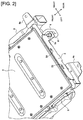
FIG. 2 ] is a perspective view illustrating a battery before mounting on a vehicle, in which a gas discharge hose is held by the sling of the first embodiment. - [
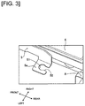
FIG. 3 ] is an enlarged perspective view illustrating the hose holding portion of the sling, which is bolted to the battery, of the first embodiment. - [
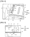
FIG. 4 ] is a perspective view illustrating a battery after mounting on a vehicle, in which the gas discharge hose of the battery is removed from the sling and assembled to a rear floor panel by insertion. - [
FIG. 5 ] is a cross-sectional view illustrating the insertion assembly state of the gas discharge hose to the rear floor panel of the first embodiment. - [
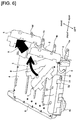
FIG. 6 ] is an operation explanatory view illustrating a state in which the sling is removed while failing to assemble the gas discharge hose in the structure for mounting a battery on a vehicle of the first embodiment. - Preferred embodiments for realizing the structure for mounting a battery on a vehicle of the present invention is explained below based on the first embodiment illustrated in the drawings.
- The configuration is described first.
- The overall configuration of the structure for mounting a battery on a vehicle and the detailed configuration of the structure for mounting a battery on a vehicle will be separately described regarding the configuration of the structure for mounting a battery on a vehicle according to the first embodiment.
-
FIG. 1 illustrates the structure for mounting a battery on a vehicle of the first embodiment when applied to a hybrid vehicle equipped with a battery at the rear of the vehicle. The overall structure of the structure for mounting a battery on a vehicle is described below, based onFIG. 1 . - The structure for mounting a battery on a vehicle comprises a
rear room 1, arear floor panel 2, a pair ofrear wheel housings battery 4, and a pair ofslings 5 and 5', and a gas discharge hose 6 (hose member) as illustrated inFIG. 1 . - The
rear room 1 is a space at the rear of the vehicle, surrounded by therear floor panel 2, the left and rightrear wheel housings battery 4 is mounted as well as being used as a luggage room. - The
battery 4 is a secondary battery which is mounted as a power source for an unillustrated motor/generator for traveling, and, for example, a lithium ion battery in which a cell module obtained by laminating a large number of cells is set inside a battery pack case is used. Thisbattery 4 is arranged in a flat state in a back left side position when viewing therear room 1 from the rearward side of the vehicle, and is bolted to therear floor panel 2, as illustrated inFIG. 1 . This bolt fixing structure has fourbrackets bolts 7, and twobrackets bolts 7. Then, in the two long side positions in the longitudinal direction of thebattery 4 are arranged a pair of batterycooling air ducts control unit 10 is arranged in an upright state in the vehicle width direction, in a vehicle front side position of thebattery 4. - The
slings 5 and 5' are temporary fastening members which are temporary mounted to move thebattery 4 with a crane or the like, and then removed after thebattery 4 is moved to a position for assembly onto a hybrid vehicle. Theslings 5 and 5' are fixed to the two short sides of thebattery 4 with respect to a vehicle width direction by twobolts bolts - The
gas discharge hose 6 is a hose for discharging gas inside thebattery 4, and one of the hose opening ends is attached beforehand in a state of being inserted into an internal chamber of thebattery 4. The other hose opening end is assembled by being inserted into a gas discharge opening 21, which is opened to the rear floor panel 2 (floor panel) located between thebattery 4 and the leftrear wheel housing 7, and opened to the outside air. -
FIG. 2 to FIG. 5 illustrate the main components of the structure for mounting a battery on a vehicle of the first embodiment. Detailed configuration of the structure for mounting a battery on a vehicle will be described below, based onFIG. 2 to FIG. 5 . - The
sling 5 is provided with a hose holding opening 51 (the hose holding portion) for holding thegas discharge hose 6 to an end position on the worker side (= the vehicle rear end position of the sling 5) until the hose is assembled to the vehicle body, as illustrated inFIG. 2 . This hose holding opening 51 sets a hose opening 52 on the worker side (= the rearward side of the vehicle) for removing thegas discharge hose 6 being held, as illustrated inFIG. 3 (refer to the worker position inFIG. 1 ). - The
sling 5 is a plate member that is fixed to asling bracket 41 of thebattery 4 by thebolts FIG. 4 , and has a pair ofhook holes FIG. 2 . Thehose holding opening 51 is an opening in thehose holding plate 5a that is integrally bent and formed from the main body portion of thesling 5 having thehook holes FIG. 3 . The slit opening surface of thehose opening 52 is configured to be a smooth curved surface so as to not damage the hose surface when inserting and withdrawing thegas discharge hose 6. - The
gas discharge hose 6 is an attached component to be assembled to a hybrid vehicle after mounting thebattery 4 on the vehicle. Agrooved packing 61 is attached to the end peripheral position of thegas discharge hose 6. The circumferential groove portion of thegrooved packing 61 secures the hose holding ability of thesling 5 with respect to the hose holding opening 51, and secures the hose holding ability with respect to the gas discharge opening 21 in a state of being assembled to therear floor panel 2 by insertion. - Next, the actions are described.
- The battery assembly work procedure and the hose assembly failure prevention action will be separately described regarding the actions of the structure for mounting a battery on a vehicle of the first embodiment.
- The assembly work procedure of the
battery 4 is carried out by progressing through (a) a sling fixing procedure, (b) a battery moving procedure, (c) a battery fixing procedure, (d) gas discharge hose assembly procedure, and (e) a sling removing procedure. Each procedure is described below. Regarding the battery fixing procedure and the gas discharge hose assembly procedure, the battery fixing procedure may be carried out after the gas discharge hose assembly procedure. - The two
slings 5 and 5' and the fourbolts battery 4. Thesling 5 is fixed to the short side position of thebattery 4 on the left side in a vehicle mounted state by the twobolts battery 4 on the right side in a vehicle mounted state by the twobolts slings 5 and 5', thegas discharge hose 6 is inserted from thehose opening 52 of thesling 5, and thegas discharge hose 6 is held against thehose holding opening 51, as illustrated inFIG. 2 . - The
battery 4 is moved from a battery placing site, where thebattery 4, to which theslings 5 and 5' are bolted and thegas discharge hose 6 is held, is placed, to the rear of the vehicle, which is the battery mounting position of the hybrid vehicle. At this time, the hooks on the wire ends are anchored to the hook holes 53 and 54 of thesling 5 and the unillustrated hook holes of the sling 5'. Then, thebattery 4 is slung up by the crane while being kept horizontal and moved from the battery placing site to the rear of the vehicle; then the slungbattery 4 is lowered to a battery fixing position of therear floor panel 2, and the anchored hooks are removed. - The
battery 4 that has been moved to the battery fixing position of therear floor panel 2 by the crane is bolted to therear floor panel 2. This bolt fixing is carried out by fixing the fourbrackets bolts 7. Then, thebrackets bolts 7. - When the
battery 4 is fixed, thegas discharge hose 6 being held to thehose holding opening 51 is withdrawn from thehose opening 52, before removing theslings 5 and 5'. Then, thegas discharge hose 6 is assembled by being inserted in a gas discharge opening 21, which is opened to arear floor panel 2 between thebattery 4 and therear wheel housing 7, as illustrated inFIG. 4 and FIG. 5 . - After assembling the
gas discharge hose 6, onesling 5 is removed from thebattery 4 by loosening and pulling out the twobolts battery 4 by loosening and pulling out the twobolts sling 5 can be easily removed as is, as long as there is no assembly failure of thegas discharge hose 6. - Of the assembly work procedure of the
battery 4 described above, there are cases in which there is an assembly failure of thegas discharge hose 6, which is present in a position that is difficult for the worker to see. The hose assembly failure prevention action is described below. - For example, one in which a hose holding portion is not provided to the sling shall be a Comparative Example. In the case of this Comparative Example, the gas discharge hose must be inserted into the vehicle body after mounting the battery on the vehicle; however, an insertion failure is often overlooked. Therefore, there is a problem that a checking step by another worker must be set as a subsequent step after the
battery 4 assembly step in order to prevent an insertion failure of the hose. - In contrast, the
sling 5 interferes with other parts unless removed, preventing the vehicle assembly, and thus is a part that cannot be forgotten to be removed; therefore, the inventors paid attention to the fact that the sling is a part that is necessarily removed after mounting the battery on the vehicle. Thus, a configuration was employed in which ahose holding opening 51 for holding thegas discharge hose 6 is provided to thesling 5, and in which ahose opening 52 is set on the worker side for removing thegas discharge hose 6 being held. - Therefore, as the
sling 5 is a part that is removed after mounting the battery on the vehicle, and by providing ahose holding opening 51 having a hose holding shape to thesling 5, in the case that thegas discharge hose 6 is failed to be inserted, thegas discharge hose 6 is caught when removing thesling 5, and the worker is able to notice the insertion failure of the hose. - In addition, since the
hose opening 52 of thehose holding opening 51 is opened on the worker side, removing thegas discharge hose 6 is easy, and the ease of assembly of thegas discharge hose 6 to the vehicle is improved. Then, in a state in which the worker lifts up and pulls thesling 5 and thegas discharge hose 6 is tensioned, if thesling 5 is pulled with a greater force, thesling 5 is easily pulled off of the gas discharge hose 6 (the pulling direction of the worker is indicated by the arrow A direction inFIG. 6 ). Accordingly, thegas discharge hose 6 can be prevented from detaching from thebattery 4 and coming out with the sling 5 (= same result as an assembly failure of the hose). Additionally, any damage to thegas discharge hose 6 can also be reduced. - Furthermore, in the case of a vehicle in which other parts cannot be assembled unless the
sling 5 is removed after mounting the battery on the vehicle, thesling 5 itself will not be forgotten to be removed, and thus the effectiveness is further enhanced. - In the first embodiment, a configuration was employed in which the
hose holding opening 51 is provided to an end position on the worker side of thesling 5. - In other words, by providing a
hose holding opening 51 at the end position on the worker side, the sling is rotated around thehose holding opening 51 as the supporting point (the rotation direction of thesling 5 is indicated by the arrow B direction inFIG. 6 ). Accordingly, since thegas discharge hose 6 is more easily detached from thesling 5, thegas discharge hose 6 can be prevented from detaching from thebattery 4 and following the sling 5 (= same result as an assembly failure of the hose). - Next, the effects are described.
- The effects listed below can be obtained with the structure for mounting a battery on a vehicle according to the first embodiment.
- (1) In a structure for mounting a battery on a vehicle that uses a
sling 5 which is mounted to move abattery 4 and which is removed after thebattery 4 is moved to a position for assembly onto a vehicle body,
thebattery 4 comprises a hose member (the gas discharge hose 6) as an attached component which is assembled onto the vehicle body after thebattery 4 is mounted on the vehicle,
thesling 5 is provided with a hose holding portion (the hose holding opening 51) for holding the hose member (the gas discharge hose 6), and
the hose holding portion (the hose holding opening 51) sets ahose opening 52 on the worker side for removing the hose member (the gas discharge hose 6) being held (FIG. 1 ).
Accordingly, it is possible to prevent the failure to assemble a hose member (the gas discharge hose 6) to a vehicle body during an operation for mounting a battery on a vehicle, while increasing the ease of assembly of the hose member (the gas discharge hose 6), which is an attached component of thebattery 4. - (2) The hose holding portion (the hose holding opening 51) is provided to an end position on the worker side of the sling 5 (
FIG. 2 ).
Accordingly, in addition to the effect of (1), the hose member (the gas discharge hose 6) is more easily detached from thesling 5, and the hose member (the gas discharge hose 6) can be prevented from detaching from thebattery 4 and following thesling 5. - (3) The
sling 5 is a plate member that is bolted to asling bracket 41 of thebattery 4,
the hose holding portion is ahose holding opening 51 which is opened to ahose holding plate 5a that is integrally bent and formed from thesling 5, and
thehose opening 52 is a slit opening formed on thehose holding plate 5a communicating with the hose holding opening 51 (FIG. 3 ).
Accordingly, in addition to the effects of (1) or (2), thehose holding opening 51 and thehose opening 52 can be easily provided to asling 5 made of a plate member that is bent machined or punched by press molding, without increasing the number of parts. - (4) The hose member is a
gas discharge hose 6 that is assembled by being pulled out from thehose opening 52 and inserted into a gas discharge opening 21, which is opened to a floor panel (the rear floor panel 2) between thebattery 4 and the wheel housing (the rear wheel housing 3) (FIG. 4 ). - Accordingly, in addition to the effects of (1) to (3), an assembly failure of the
gas discharge hose 6, which is present in a position that is difficult to see by the worker, can be prevented. - The structure for mounting a battery on a vehicle of the present invention was described above based on the first embodiment, but specific configurations thereof are not limited to the first embodiment, and various modifications and additions to the design can be made without departing from the scope of the invention according to each claim in the Claims.
- In the first embodiment, an example was shown in which a worker mounts the
battery 4 and thegas discharge hose 6 from the back door side on the rearward side of the vehicle. However, the battery and the hose member may be, for example, mounted from the rear seat side, mounted by a worker from the side door side in the vehicle width direction, or mounted by a worker from the frontward side of the vehicle. - In the first embodiment, an example was shown in which the
hose holding opening 51 provided integrally with thesling 5 is used as the hose holding portion. However, various structures other than a hose holding opening may be used as the hose holding portion, as long as the configuration makes holding the hose member possible. Additionally, the hose holding portion may be configured separately from the sling, and be integrally coupled to the sling by retrofitting. - In the first embodiment, an example was shown in which the
gas discharge hose 6 is used as the hose member. However, other than a gas discharge hose, the hose member may be a hose-like member that is attached to the battery, such as a condensed water discharge hose or a harness member. - In the first embodiment, an example was shown in which the structure for mounting a battery on a vehicle of the present invention is applied to the
battery 4 that is mounted on the rear of the vehicle that is a hybrid vehicle. However, the structure for mounting a battery on a vehicle of the present invention may be applied to a battery that is mounted to various positions, such as the front of the vehicle. Furthermore, the invention may also be applied to a battery that is mounted on an electric vehicle or an engine vehicle. - This application claims the right of priority based on Japanese Patent Application No.
2013-164329
Claims (4)
- A structure for mounting a battery on a vehicle that uses a sling which is mounted to move the battery and which is removed after the battery is moved to a position for assembly onto a vehicle body, wherein
the battery comprises a hose member as an attached component which is assembled onto the vehicle body after the battery is mounted on the vehicle,
the sling is provided with a hose holding portion for holding the hose member, and
the hose holding portion sets a hose opening on the worker side for removing the hose member being held. - The structure for mounting a battery on a vehicle according to claim 1, wherein
the hose holding portion is provided to an end position on the worker side of the sling. - The structure for mounting a battery on a vehicle according to claim 1 or 2, wherein
the sling is a plate member that is bolted to a sling bracket of the battery,
the hose holding portion is a hose holding opening which is opened to a hose holding plate that is integrally bent and formed from the sling, and
the hose opening is a slit opening formed in the hose holding plate communicating with the hose holding opening. - The structure for mounting a battery on a vehicle according to any one of claims 1 to 3, wherein
the hose member is a gas discharge hose that is assembled by being pulled out from the hose opening and inserted to a gas discharge opening, which is opened to a floor panel between the battery and a wheel housing.
Applications Claiming Priority (2)
| Application Number | Priority Date | Filing Date | Title |
|---|---|---|---|
| JP2013164329 | 2013-08-07 | ||
| PCT/JP2014/067102 WO2015019741A1 (en) | 2013-08-07 | 2014-06-27 | Structure for mounting battery on vehicle |
Publications (3)
| Publication Number | Publication Date |
|---|---|
| EP3031647A1 true EP3031647A1 (en) | 2016-06-15 |
| EP3031647A4 EP3031647A4 (en) | 2016-07-20 |
| EP3031647B1 EP3031647B1 (en) | 2018-09-05 |
Family
ID=52461080
Family Applications (1)
| Application Number | Title | Priority Date | Filing Date |
|---|---|---|---|
| EP14833730.6A Active EP3031647B1 (en) | 2013-08-07 | 2014-06-27 | Structure for mounting battery on vehicle |
Country Status (8)
| Country | Link |
|---|---|
| US (1) | US9590217B2 (en) |
| EP (1) | EP3031647B1 (en) |
| JP (1) | JP6056977B2 (en) |
| CN (1) | CN105408150B (en) |
| MX (1) | MX349872B (en) |
| MY (1) | MY161715A (en) |
| RU (1) | RU2641020C2 (en) |
| WO (1) | WO2015019741A1 (en) |
Families Citing this family (9)
| Publication number | Priority date | Publication date | Assignee | Title |
|---|---|---|---|---|
| JP2022523625A (en) | 2019-01-07 | 2022-04-26 | カヌー テクノロジーズ インク | Battery pack heat management methods and systems |
| CA3141572C (en) | 2019-05-20 | 2024-02-27 | Canoo Technologies Inc. | Electric vehicle platform |
| US12420869B2 (en) | 2019-07-02 | 2025-09-23 | Canoo Technologies Inc. | Method to reduced lateral deflection of longitudinal members in side impact |
| CA3145383C (en) | 2019-07-02 | 2025-05-27 | Canoo Technologies Inc. | Impact features |
| US11618292B2 (en) | 2019-09-09 | 2023-04-04 | Canoo Technologies Inc. | Suspension system |
| WO2021055980A1 (en) * | 2019-09-20 | 2021-03-25 | Canoo Inc. | Electric vehicle battery enclosure |
| CN114728603B (en) | 2019-09-20 | 2024-08-27 | 卡诺技术股份有限公司 | Vehicle seating system |
| US20240391348A1 (en) * | 2023-05-26 | 2024-11-28 | Caterpillar Underground Mining Pty. Ltd. | Alignment system for swappable vehicle battery |
| JP2025156971A (en) * | 2024-04-02 | 2025-10-15 | トヨタ自動車株式会社 | vehicle |
Family Cites Families (11)
| Publication number | Priority date | Publication date | Assignee | Title |
|---|---|---|---|---|
| US3093515A (en) * | 1960-05-31 | 1963-06-11 | Stauffer Chemical Co | Battery case |
| JPS59110960U (en) * | 1983-01-18 | 1984-07-26 | 本田技研工業株式会社 | Vehicle wet storage battery fixing device |
| FI86926C (en) * | 1988-04-14 | 1992-10-26 | Neste Oy | FAUNTEKANISM FOER ACKUMULATOR |
| US6153331A (en) * | 1999-05-14 | 2000-11-28 | Delphi Technologies, Inc. | Battery handle holddown |
| ES1046536Y (en) * | 2000-06-13 | 2001-06-01 | Tudor Acumulador | HANDLE FOR BATTERY OF ELECTRIC ACCUMULATORS. |
| JP2002063884A (en) * | 2000-08-17 | 2002-02-28 | Nippon Yusoki Co Ltd | Battery replacement device for battery car |
| US8632902B2 (en) * | 2007-12-06 | 2014-01-21 | GM Global Technology Operations LLC | Device for retaining a battery |
| JP2010272520A (en) * | 2009-04-24 | 2010-12-02 | Nissan Motor Co Ltd | Assembled battery |
| US8592068B2 (en) | 2009-04-24 | 2013-11-26 | Nissan Motor Co., Ltd. | Battery pack |
| US8679662B2 (en) * | 2011-01-04 | 2014-03-25 | Ford Global Technologies, Llc | Battery assembly with gas discharge mechanism |
| JP6004774B2 (en) * | 2011-12-16 | 2016-10-12 | モテックス プロダクツ カンパニー リミテッド | Battery removal device for electric vehicles |
-
2014
- 2014-06-27 US US14/903,643 patent/US9590217B2/en active Active
- 2014-06-27 CN CN201480042312.7A patent/CN105408150B/en active Active
- 2014-06-27 MX MX2016001620A patent/MX349872B/en active IP Right Grant
- 2014-06-27 RU RU2016107734A patent/RU2641020C2/en active
- 2014-06-27 WO PCT/JP2014/067102 patent/WO2015019741A1/en not_active Ceased
- 2014-06-27 EP EP14833730.6A patent/EP3031647B1/en active Active
- 2014-06-27 MY MYPI2016700240A patent/MY161715A/en unknown
- 2014-06-27 JP JP2015530749A patent/JP6056977B2/en active Active
Also Published As
| Publication number | Publication date |
|---|---|
| US9590217B2 (en) | 2017-03-07 |
| MX349872B (en) | 2017-08-17 |
| RU2641020C2 (en) | 2018-01-15 |
| EP3031647B1 (en) | 2018-09-05 |
| WO2015019741A1 (en) | 2015-02-12 |
| CN105408150B (en) | 2017-08-11 |
| RU2016107734A (en) | 2017-09-14 |
| MX2016001620A (en) | 2016-05-02 |
| CN105408150A (en) | 2016-03-16 |
| US20160164055A1 (en) | 2016-06-09 |
| JP6056977B2 (en) | 2017-01-11 |
| EP3031647A4 (en) | 2016-07-20 |
| MY161715A (en) | 2017-05-15 |
| JPWO2015019741A1 (en) | 2017-03-02 |
Similar Documents
| Publication | Publication Date | Title |
|---|---|---|
| EP3031647B1 (en) | Structure for mounting battery on vehicle | |
| EP2905160B1 (en) | Vehicle apparatus attaching structure | |
| CN104999896B (en) | Electrical equipment is fixed to the fixed structure of vehicle | |
| US9511657B2 (en) | Replaceable battery module for an electric vehicle | |
| JP5849720B2 (en) | Battery pack water injection structure | |
| CN103380251B (en) | Electric work vehicle and pedestal thereof | |
| CN101264735B (en) | Cable connection structure in electric vehicle | |
| US9837690B2 (en) | Battery cooling fan mounting | |
| JPWO2015019742A1 (en) | Battery body mounting structure | |
| EP3385103B1 (en) | High-voltage device | |
| DE102011118412A1 (en) | Cooling channel structure for a battery unit | |
| DE102012102938A1 (en) | battery | |
| CN217022207U (en) | Installing support and car of charging seat fill soon or slowly | |
| JP6378881B2 (en) | Vehicle charging device | |
| US9610850B2 (en) | Vehicle charging unit | |
| EP4470841A1 (en) | Attachment structure for wire harness | |
| US9029697B2 (en) | Onboard device | |
| JP2019160590A (en) | Vehicle battery pack | |
| JP5970389B2 (en) | Terminal protection cover and terminal protection method | |
| CN111169407A (en) | Temporary locking structure for ends of wire harnesses | |
| CN210082922U (en) | A longitudinal beam middle section assembly structure for installing a power battery and a vehicle | |
| CN115084616B (en) | Fuel cell stack casing and method for assembling fuel cell stack casing | |
| US20260005497A1 (en) | Impact releaseable cable bundler router | |
| JP2013091400A (en) | Positioning structure of on-vehicle electronic equipment | |
| JP2010209520A (en) | Construction machinery |
Legal Events
| Date | Code | Title | Description |
|---|---|---|---|
| PUAI | Public reference made under article 153(3) epc to a published international application that has entered the european phase |
Free format text: ORIGINAL CODE: 0009012 |
|
| 17P | Request for examination filed |
Effective date: 20160302 |
|
| AK | Designated contracting states |
Kind code of ref document: A1 Designated state(s): AL AT BE BG CH CY CZ DE DK EE ES FI FR GB GR HR HU IE IS IT LI LT LU LV MC MK MT NL NO PL PT RO RS SE SI SK SM TR |
|
| AX | Request for extension of the european patent |
Extension state: BA ME |
|
| A4 | Supplementary search report drawn up and despatched |
Effective date: 20160622 |
|
| RIC1 | Information provided on ipc code assigned before grant |
Ipc: H01M 2/10 20060101ALI20160616BHEP Ipc: B60K 1/04 20060101AFI20160616BHEP Ipc: H01M 2/12 20060101ALI20160616BHEP |
|
| DAX | Request for extension of the european patent (deleted) | ||
| STAA | Information on the status of an ep patent application or granted ep patent |
Free format text: STATUS: EXAMINATION IS IN PROGRESS |
|
| 17Q | First examination report despatched |
Effective date: 20170413 |
|
| GRAP | Despatch of communication of intention to grant a patent |
Free format text: ORIGINAL CODE: EPIDOSNIGR1 |
|
| STAA | Information on the status of an ep patent application or granted ep patent |
Free format text: STATUS: GRANT OF PATENT IS INTENDED |
|
| INTG | Intention to grant announced |
Effective date: 20180614 |
|
| GRAS | Grant fee paid |
Free format text: ORIGINAL CODE: EPIDOSNIGR3 |
|
| GRAA | (expected) grant |
Free format text: ORIGINAL CODE: 0009210 |
|
| STAA | Information on the status of an ep patent application or granted ep patent |
Free format text: STATUS: THE PATENT HAS BEEN GRANTED |
|
| AK | Designated contracting states |
Kind code of ref document: B1 Designated state(s): AL AT BE BG CH CY CZ DE DK EE ES FI FR GB GR HR HU IE IS IT LI LT LU LV MC MK MT NL NO PL PT RO RS SE SI SK SM TR |
|
| REG | Reference to a national code |
Ref country code: GB Ref legal event code: FG4D |
|
| REG | Reference to a national code |
Ref country code: CH Ref legal event code: EP |
|
| REG | Reference to a national code |
Ref country code: AT Ref legal event code: REF Ref document number: 1037386 Country of ref document: AT Kind code of ref document: T Effective date: 20180915 |
|
| REG | Reference to a national code |
Ref country code: IE Ref legal event code: FG4D |
|
| REG | Reference to a national code |
Ref country code: DE Ref legal event code: R096 Ref document number: 602014032010 Country of ref document: DE |
|
| REG | Reference to a national code |
Ref country code: NL Ref legal event code: MP Effective date: 20180905 |
|
| REG | Reference to a national code |
Ref country code: LT Ref legal event code: MG4D |
|
| PG25 | Lapsed in a contracting state [announced via postgrant information from national office to epo] |
Ref country code: GR Free format text: LAPSE BECAUSE OF FAILURE TO SUBMIT A TRANSLATION OF THE DESCRIPTION OR TO PAY THE FEE WITHIN THE PRESCRIBED TIME-LIMIT Effective date: 20181206 Ref country code: NO Free format text: LAPSE BECAUSE OF FAILURE TO SUBMIT A TRANSLATION OF THE DESCRIPTION OR TO PAY THE FEE WITHIN THE PRESCRIBED TIME-LIMIT Effective date: 20181205 Ref country code: BG Free format text: LAPSE BECAUSE OF FAILURE TO SUBMIT A TRANSLATION OF THE DESCRIPTION OR TO PAY THE FEE WITHIN THE PRESCRIBED TIME-LIMIT Effective date: 20181205 Ref country code: SE Free format text: LAPSE BECAUSE OF FAILURE TO SUBMIT A TRANSLATION OF THE DESCRIPTION OR TO PAY THE FEE WITHIN THE PRESCRIBED TIME-LIMIT Effective date: 20180905 Ref country code: LT Free format text: LAPSE BECAUSE OF FAILURE TO SUBMIT A TRANSLATION OF THE DESCRIPTION OR TO PAY THE FEE WITHIN THE PRESCRIBED TIME-LIMIT Effective date: 20180905 Ref country code: FI Free format text: LAPSE BECAUSE OF FAILURE TO SUBMIT A TRANSLATION OF THE DESCRIPTION OR TO PAY THE FEE WITHIN THE PRESCRIBED TIME-LIMIT Effective date: 20180905 Ref country code: RS Free format text: LAPSE BECAUSE OF FAILURE TO SUBMIT A TRANSLATION OF THE DESCRIPTION OR TO PAY THE FEE WITHIN THE PRESCRIBED TIME-LIMIT Effective date: 20180905 |
|
| REG | Reference to a national code |
Ref country code: AT Ref legal event code: MK05 Ref document number: 1037386 Country of ref document: AT Kind code of ref document: T Effective date: 20180905 |
|
| PG25 | Lapsed in a contracting state [announced via postgrant information from national office to epo] |
Ref country code: AL Free format text: LAPSE BECAUSE OF FAILURE TO SUBMIT A TRANSLATION OF THE DESCRIPTION OR TO PAY THE FEE WITHIN THE PRESCRIBED TIME-LIMIT Effective date: 20180905 Ref country code: LV Free format text: LAPSE BECAUSE OF FAILURE TO SUBMIT A TRANSLATION OF THE DESCRIPTION OR TO PAY THE FEE WITHIN THE PRESCRIBED TIME-LIMIT Effective date: 20180905 Ref country code: HR Free format text: LAPSE BECAUSE OF FAILURE TO SUBMIT A TRANSLATION OF THE DESCRIPTION OR TO PAY THE FEE WITHIN THE PRESCRIBED TIME-LIMIT Effective date: 20180905 |
|
| PG25 | Lapsed in a contracting state [announced via postgrant information from national office to epo] |
Ref country code: EE Free format text: LAPSE BECAUSE OF FAILURE TO SUBMIT A TRANSLATION OF THE DESCRIPTION OR TO PAY THE FEE WITHIN THE PRESCRIBED TIME-LIMIT Effective date: 20180905 Ref country code: PL Free format text: LAPSE BECAUSE OF FAILURE TO SUBMIT A TRANSLATION OF THE DESCRIPTION OR TO PAY THE FEE WITHIN THE PRESCRIBED TIME-LIMIT Effective date: 20180905 Ref country code: AT Free format text: LAPSE BECAUSE OF FAILURE TO SUBMIT A TRANSLATION OF THE DESCRIPTION OR TO PAY THE FEE WITHIN THE PRESCRIBED TIME-LIMIT Effective date: 20180905 Ref country code: IT Free format text: LAPSE BECAUSE OF FAILURE TO SUBMIT A TRANSLATION OF THE DESCRIPTION OR TO PAY THE FEE WITHIN THE PRESCRIBED TIME-LIMIT Effective date: 20180905 Ref country code: RO Free format text: LAPSE BECAUSE OF FAILURE TO SUBMIT A TRANSLATION OF THE DESCRIPTION OR TO PAY THE FEE WITHIN THE PRESCRIBED TIME-LIMIT Effective date: 20180905 Ref country code: NL Free format text: LAPSE BECAUSE OF FAILURE TO SUBMIT A TRANSLATION OF THE DESCRIPTION OR TO PAY THE FEE WITHIN THE PRESCRIBED TIME-LIMIT Effective date: 20180905 Ref country code: ES Free format text: LAPSE BECAUSE OF FAILURE TO SUBMIT A TRANSLATION OF THE DESCRIPTION OR TO PAY THE FEE WITHIN THE PRESCRIBED TIME-LIMIT Effective date: 20180905 Ref country code: CZ Free format text: LAPSE BECAUSE OF FAILURE TO SUBMIT A TRANSLATION OF THE DESCRIPTION OR TO PAY THE FEE WITHIN THE PRESCRIBED TIME-LIMIT Effective date: 20180905 Ref country code: IS Free format text: LAPSE BECAUSE OF FAILURE TO SUBMIT A TRANSLATION OF THE DESCRIPTION OR TO PAY THE FEE WITHIN THE PRESCRIBED TIME-LIMIT Effective date: 20190105 |
|
| PG25 | Lapsed in a contracting state [announced via postgrant information from national office to epo] |
Ref country code: SK Free format text: LAPSE BECAUSE OF FAILURE TO SUBMIT A TRANSLATION OF THE DESCRIPTION OR TO PAY THE FEE WITHIN THE PRESCRIBED TIME-LIMIT Effective date: 20180905 Ref country code: PT Free format text: LAPSE BECAUSE OF FAILURE TO SUBMIT A TRANSLATION OF THE DESCRIPTION OR TO PAY THE FEE WITHIN THE PRESCRIBED TIME-LIMIT Effective date: 20190105 Ref country code: SM Free format text: LAPSE BECAUSE OF FAILURE TO SUBMIT A TRANSLATION OF THE DESCRIPTION OR TO PAY THE FEE WITHIN THE PRESCRIBED TIME-LIMIT Effective date: 20180905 |
|
| REG | Reference to a national code |
Ref country code: DE Ref legal event code: R097 Ref document number: 602014032010 Country of ref document: DE |
|
| PLBE | No opposition filed within time limit |
Free format text: ORIGINAL CODE: 0009261 |
|
| STAA | Information on the status of an ep patent application or granted ep patent |
Free format text: STATUS: NO OPPOSITION FILED WITHIN TIME LIMIT |
|
| PG25 | Lapsed in a contracting state [announced via postgrant information from national office to epo] |
Ref country code: DK Free format text: LAPSE BECAUSE OF FAILURE TO SUBMIT A TRANSLATION OF THE DESCRIPTION OR TO PAY THE FEE WITHIN THE PRESCRIBED TIME-LIMIT Effective date: 20180905 |
|
| 26N | No opposition filed |
Effective date: 20190606 |
|
| PG25 | Lapsed in a contracting state [announced via postgrant information from national office to epo] |
Ref country code: SI Free format text: LAPSE BECAUSE OF FAILURE TO SUBMIT A TRANSLATION OF THE DESCRIPTION OR TO PAY THE FEE WITHIN THE PRESCRIBED TIME-LIMIT Effective date: 20180905 |
|
| PG25 | Lapsed in a contracting state [announced via postgrant information from national office to epo] |
Ref country code: MC Free format text: LAPSE BECAUSE OF FAILURE TO SUBMIT A TRANSLATION OF THE DESCRIPTION OR TO PAY THE FEE WITHIN THE PRESCRIBED TIME-LIMIT Effective date: 20180905 |
|
| REG | Reference to a national code |
Ref country code: CH Ref legal event code: PL |
|
| REG | Reference to a national code |
Ref country code: BE Ref legal event code: MM Effective date: 20190630 |
|
| PG25 | Lapsed in a contracting state [announced via postgrant information from national office to epo] |
Ref country code: TR Free format text: LAPSE BECAUSE OF FAILURE TO SUBMIT A TRANSLATION OF THE DESCRIPTION OR TO PAY THE FEE WITHIN THE PRESCRIBED TIME-LIMIT Effective date: 20180905 |
|
| PG25 | Lapsed in a contracting state [announced via postgrant information from national office to epo] |
Ref country code: IE Free format text: LAPSE BECAUSE OF NON-PAYMENT OF DUE FEES Effective date: 20190627 |
|
| PG25 | Lapsed in a contracting state [announced via postgrant information from national office to epo] |
Ref country code: BE Free format text: LAPSE BECAUSE OF NON-PAYMENT OF DUE FEES Effective date: 20190630 Ref country code: LU Free format text: LAPSE BECAUSE OF NON-PAYMENT OF DUE FEES Effective date: 20190627 Ref country code: LI Free format text: LAPSE BECAUSE OF NON-PAYMENT OF DUE FEES Effective date: 20190630 Ref country code: CH Free format text: LAPSE BECAUSE OF NON-PAYMENT OF DUE FEES Effective date: 20190630 |
|
| PG25 | Lapsed in a contracting state [announced via postgrant information from national office to epo] |
Ref country code: CY Free format text: LAPSE BECAUSE OF FAILURE TO SUBMIT A TRANSLATION OF THE DESCRIPTION OR TO PAY THE FEE WITHIN THE PRESCRIBED TIME-LIMIT Effective date: 20180905 |
|
| PG25 | Lapsed in a contracting state [announced via postgrant information from national office to epo] |
Ref country code: MT Free format text: LAPSE BECAUSE OF FAILURE TO SUBMIT A TRANSLATION OF THE DESCRIPTION OR TO PAY THE FEE WITHIN THE PRESCRIBED TIME-LIMIT Effective date: 20180905 Ref country code: HU Free format text: LAPSE BECAUSE OF FAILURE TO SUBMIT A TRANSLATION OF THE DESCRIPTION OR TO PAY THE FEE WITHIN THE PRESCRIBED TIME-LIMIT; INVALID AB INITIO Effective date: 20140627 |
|
| PG25 | Lapsed in a contracting state [announced via postgrant information from national office to epo] |
Ref country code: MK Free format text: LAPSE BECAUSE OF FAILURE TO SUBMIT A TRANSLATION OF THE DESCRIPTION OR TO PAY THE FEE WITHIN THE PRESCRIBED TIME-LIMIT Effective date: 20180905 |
|
| PGFP | Annual fee paid to national office [announced via postgrant information from national office to epo] |
Ref country code: DE Payment date: 20250520 Year of fee payment: 12 |
|
| PGFP | Annual fee paid to national office [announced via postgrant information from national office to epo] |
Ref country code: GB Payment date: 20250520 Year of fee payment: 12 |
|
| PGFP | Annual fee paid to national office [announced via postgrant information from national office to epo] |
Ref country code: FR Payment date: 20250520 Year of fee payment: 12 |