EP3031633A1 - Air maintenance tire and valve assembly - Google Patents
Air maintenance tire and valve assembly Download PDFInfo
- Publication number
- EP3031633A1 EP3031633A1 EP15197289.0A EP15197289A EP3031633A1 EP 3031633 A1 EP3031633 A1 EP 3031633A1 EP 15197289 A EP15197289 A EP 15197289A EP 3031633 A1 EP3031633 A1 EP 3031633A1
- Authority
- EP
- European Patent Office
- Prior art keywords
- tire
- groove
- tube
- passageway
- previous
- Prior art date
- Legal status (The legal status is an assumption and is not a legal conclusion. Google has not performed a legal analysis and makes no representation as to the accuracy of the status listed.)
- Granted
Links
- 238000012423 maintenance Methods 0.000 title description 3
- 239000011324 bead Substances 0.000 claims abstract description 4
- 230000002572 peristaltic effect Effects 0.000 claims description 8
- 238000005096 rolling process Methods 0.000 claims description 4
- 239000000853 adhesive Substances 0.000 claims description 2
- 230000001070 adhesive effect Effects 0.000 claims description 2
- 239000012530 fluid Substances 0.000 claims 1
- 238000005452 bending Methods 0.000 description 7
- 230000006835 compression Effects 0.000 description 5
- 238000007906 compression Methods 0.000 description 5
- 238000005086 pumping Methods 0.000 description 2
- 230000004888 barrier function Effects 0.000 description 1
- 150000001875 compounds Chemical class 0.000 description 1
- 238000010276 construction Methods 0.000 description 1
- 230000008602 contraction Effects 0.000 description 1
- 230000001419 dependent effect Effects 0.000 description 1
- 238000009792 diffusion process Methods 0.000 description 1
- 239000000446 fuel Substances 0.000 description 1
- 239000000463 material Substances 0.000 description 1
- 230000007246 mechanism Effects 0.000 description 1
- 238000012544 monitoring process Methods 0.000 description 1
- 230000037361 pathway Effects 0.000 description 1
- 230000009467 reduction Effects 0.000 description 1
- 230000000246 remedial effect Effects 0.000 description 1
Images




Classifications
-
- B—PERFORMING OPERATIONS; TRANSPORTING
- B60—VEHICLES IN GENERAL
- B60C—VEHICLE TYRES; TYRE INFLATION; TYRE CHANGING; CONNECTING VALVES TO INFLATABLE ELASTIC BODIES IN GENERAL; DEVICES OR ARRANGEMENTS RELATED TO TYRES
- B60C23/00—Devices for measuring, signalling, controlling, or distributing tyre pressure or temperature, specially adapted for mounting on vehicles; Arrangement of tyre inflating devices on vehicles, e.g. of pumps or of tanks; Tyre cooling arrangements
- B60C23/10—Arrangement of tyre-inflating pumps mounted on vehicles
- B60C23/12—Arrangement of tyre-inflating pumps mounted on vehicles operated by a running wheel
- B60C23/121—Arrangement of tyre-inflating pumps mounted on vehicles operated by a running wheel the pumps being mounted on the tyres
- B60C23/123—Elongate peristaltic pumps
-
- B—PERFORMING OPERATIONS; TRANSPORTING
- B60—VEHICLES IN GENERAL
- B60C—VEHICLE TYRES; TYRE INFLATION; TYRE CHANGING; CONNECTING VALVES TO INFLATABLE ELASTIC BODIES IN GENERAL; DEVICES OR ARRANGEMENTS RELATED TO TYRES
- B60C23/00—Devices for measuring, signalling, controlling, or distributing tyre pressure or temperature, specially adapted for mounting on vehicles; Arrangement of tyre inflating devices on vehicles, e.g. of pumps or of tanks; Tyre cooling arrangements
- B60C23/001—Devices for manually or automatically controlling or distributing tyre pressure whilst the vehicle is moving
-
- B—PERFORMING OPERATIONS; TRANSPORTING
- B60—VEHICLES IN GENERAL
- B60C—VEHICLE TYRES; TYRE INFLATION; TYRE CHANGING; CONNECTING VALVES TO INFLATABLE ELASTIC BODIES IN GENERAL; DEVICES OR ARRANGEMENTS RELATED TO TYRES
- B60C23/00—Devices for measuring, signalling, controlling, or distributing tyre pressure or temperature, specially adapted for mounting on vehicles; Arrangement of tyre inflating devices on vehicles, e.g. of pumps or of tanks; Tyre cooling arrangements
- B60C23/10—Arrangement of tyre-inflating pumps mounted on vehicles
-
- B—PERFORMING OPERATIONS; TRANSPORTING
- B60—VEHICLES IN GENERAL
- B60C—VEHICLE TYRES; TYRE INFLATION; TYRE CHANGING; CONNECTING VALVES TO INFLATABLE ELASTIC BODIES IN GENERAL; DEVICES OR ARRANGEMENTS RELATED TO TYRES
- B60C23/00—Devices for measuring, signalling, controlling, or distributing tyre pressure or temperature, specially adapted for mounting on vehicles; Arrangement of tyre inflating devices on vehicles, e.g. of pumps or of tanks; Tyre cooling arrangements
- B60C23/10—Arrangement of tyre-inflating pumps mounted on vehicles
- B60C23/12—Arrangement of tyre-inflating pumps mounted on vehicles operated by a running wheel
- B60C23/135—Arrangement of tyre-inflating pumps mounted on vehicles operated by a running wheel activated due to tyre deformation
Definitions
- the invention relates generally to air maintenance tires and, more specifically, to a tire assembly incorporating an air pumping mechanism for maintaining tire air pressure.
- the invention relates to a tire in accordance with claim 1.
- a self-inflating tire assembly may also includes a rim having a tire mounting surface extending between first and second rim flanges and comprises a tire for mounting to the rim tire mounting surface, the tire having a tire cavity, and first and second sidewalls extending respectively from first and second tire bead regions to a tire tread region.
- a sidewall groove is positioned within a compression zone of the tire, and an air tube is positioned within the sidewall groove in contacting engagement with opposite groove surfaces at least partially surrounding the air tube.
- the sidewall groove operatively bends within the compression side of the bending region responsive to a bending strain within the rolling tire footprint to compress the air tube from an expanded diameter to a flat diameter adjacent the rolling tire footprint, whereby forcing evacuated air from a flattened air tube segment along the air passageway.
- Axial and “axially” means lines or directions that are parallel to the axis of rotation of the tire.
- “Circumferential” means lines or directions extending along the perimeter of the surface of the annular tread perpendicular to the axial direction.
- Equatorial Centerplane means the plane perpendicular to the tire's axis of rotation and passing through the center of the tread.
- “Footprint” means the contact patch or area of contact of the tire tread with a flat surface at zero speed and under normal load and pressure.
- “Lateral” means an axial direction.
- Outboard side means the side of the tire farthest away from the vehicle when the tire is mounted on a wheel and the wheel is mounted on the vehicle.
- Periodaltic means operating by means of wave-like contractions that propel contained matter, such as air, along tubular pathways.
- Ring and radially means directions radially toward or away from the axis of rotation of the tire.
- a tire assembly 10 including a tire 12.
- the tire comprises a peristaltic pump assembly 14.
- a tire wheel 16 is shown.
- the tire mounts in conventional fashion to the wheel 16.
- the wheel 16 has a rim 28 with rim mounting flanges 26.
- the tire is preferably of conventional construction, having a pair of sidewalls 32 extending from opposite bead areas 34 to a crown or tire read region 38.
- the tire 12 has a tire cavity 40 which is enclosed by the tire 12 and the rim 28.
- the pump assembly 14 includes an air tube 50 mounted in a passageway or groove 60.
- the tube 50 is formed of a resilient, flexible material such as plastic or rubber compounds that are capable of withstanding repeated deformation cycles. So constructed, the tube may deform within a tire into a flattened condition subject to external force and, upon removal of such force, return to an original sectional configuration.
- the cross-section of the tube 50 in an unstressed state is generally circular with an inner round hole 52 formed by the tube wall 54.
- the tube 50 is of a diameter sufficient to operatively pass a requisite volume of air sufficient for the purpose of pumping air into the tire cavity 40 to maintain the tire 12 at a preferred inflation pressure.
- air tube 50 shown in this embodiment is annular for a 360 degree pump
- the air tube need not be annular and may have any sufficient length for example, a 180 degree pump.
- the peristaltic pump assembly 14 may further include a regulator device 70 and an air intake and filter assembly 75.
- the regulator device 70 functions to prevent air from entering the peristaltic pump through the air intake and filter assembly 75 if the tire air pressure in cavity 40 of the tire is greater than a selectable set point pressure. If the tire cavity pressure is below the set point pressure, the regulator 70 opens an air passage connected to the pump inlet of the peristaltic pump to allow outside air to flow into the peristaltic pump.
- the regulator may be as described in WO-A-2015/105848 , which is hereby incorporated by reference.
- a compressive force 104 is directed into the tire from the footprint 100 and acts to flatten a portion of the air tube passageway as shown in Fig. 4B .
- the pump tube will be sequentially flattened or squeezed opposite the tire footprint in a segment by segment manner in a direction opposite to the direction of tire rotation.
- the sequential flattening of the tube passageway 50 segment by segment causes evacuated air from the flattened segments to be pumped to the outlet, into the regulator device and then into the tire cavity 40.
- the flattened tube segments are refilled with air from the air intake filter assembly 75 until the regulator shuts off flow to the pump when the set pressure is reached.
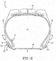
- a preferred location for the air tube assembly 14 is as shown in Fig. 2 .
- the air tube assembly 14 is preferably mounted in an area of the tire that undergoes bending strain. Utilizing the bending strain within a bending region of a sidewall avoids the need to compress the air tube by pinching the air tube against a relatively hard barrier such as the tire assembly rim. Potential damage to the air tube from contact with the rim is thus avoided and the structural integrity of the air tube is preserved throughout the life cycle of the tire.
- the tube 50 is located within a groove 60.
- the groove 60 is preferably located in the lower sidewall 32 of the tire 12, and more preferably, in the lower sidewall area radially outward of the upper rim flange when mounted on a wheel, as shown in Fig. 2 , where bending deformation of the tire helps to achieve tube pinching.
- the tube 50 is closed by compression strain bending the groove 60 within a rolling tire footprint.
- the location of the tube 50 in the sidewall 30 affords the user freedom of placement and avoids contact between the tube 50 and the rim flange 26.
- the higher placement of the tube 50 in the groove 60 uses the deformation of the sidewall as it passes through the tire footprint to close the tube.
- the groove 60 is shown in an unloaded state in Fig. 3A.
- Fig. 3A illustrates the tube in phantom positioned within the groove 60.
- the tube 50 has a diameter D greater than the width of the groove 60, such that there is an interference fit of the tube 50 in the width direction, when the tube 50 is mounted in the groove 60.
- the groove 60 has a length L that is in the range of from 2 to 4 times the width W, and more preferably in the range of from 3 to 4 times the width W.
- the outside diameter D of the tube 50 is preferably greater than the width W of the groove, and more preferably in the range of from 1.5 to 2 times the width W of the groove.
- the length of the groove L is greater than the outside diameter D of the tube 50, so that when the tube is inserted in the groove 60, the tube 50 does not fill the entire groove 60 leaving a gap 110.
- the gap 110 allows room for filing the entire groove 60 with an adhesive to secure the tube within the groove.
- the tube does not have an interference fit with respect to the groove length.
- the groove 60 further includes a neck portion 65 with a reduced width N located at the groove inlet.
- the reduced width N is in the range of 40-60% of the width W.
- the groove 60 is defined by a first and second sidewalls 62, 63, a portion of which are in parallel relation to each other. The first and second sidewalls 62, 63 join together at the terminal end 64 of the groove 60.
- a coverstrip 130 may be inserted into the groove inlet to secure the tube inside the tire.
- the coverstrip 130 preferably has a circular recessed face 132 that is positioned against the curved outer surface 51 of the tube 50.
- the coverstrip 130 preferably has two opposed neck portions 134, 136 that are received against the groove neck 65.
- the coverstrip 130 preferably has outer end portions 138, 140 that are mounted in the beveled portion 69 of the groove 60.
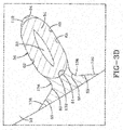
- Fig 3D illustrates the tube and groove in the assembled position when the tire is in an unloaded state. When the tube is mounted into the groove, the tube cross-sectional shape is generally elliptical.
- FIG. 4A illustrates the groove and tube assembly when the tire is rotating under load, showing the tube in the open position.
- Fig. 4B illustrates when the groove and tube assembly has rotated into the footprint area, so that the tire sidewall 32 is under compression, and the tube 52 is in the closed position.
Landscapes
- Engineering & Computer Science (AREA)
- Mechanical Engineering (AREA)
- Tires In General (AREA)
Abstract
Description
- The invention relates generally to air maintenance tires and, more specifically, to a tire assembly incorporating an air pumping mechanism for maintaining tire air pressure.
- The invention was made with government support under DE-
EE0005447 - Normal air diffusion reduces tire pressure over time. The natural state of tires is under inflated. Accordingly, drivers must repeatedly act to maintain tire pressures or they will see reduced fuel economy, tire life and reduced vehicle braking and handling performance. Tire Pressure Monitoring Systems have been proposed to warn drivers when tire pressure is significantly low. Such systems, however, remain dependant upon the driver taking remedial action when warned to re-inflate a tire to recommended pressure. It is a desirable, therefore, to incorporate an air maintenance feature within a tire that will self-maintain the tire air pressure in order to compensate for any reduction in tire pressure over time without a need for driver intervention. A self-inflating tire is shown in
EP-A-2 338 703 . - The invention relates to a tire in accordance with claim 1.
- Dependent claims refer to preferred embodiments of the invention.
- According to a preferred aspect of the invention, a self-inflating tire assembly may also includes a rim having a tire mounting surface extending between first and second rim flanges and comprises a tire for mounting to the rim tire mounting surface, the tire having a tire cavity, and first and second sidewalls extending respectively from first and second tire bead regions to a tire tread region. A sidewall groove is positioned within a compression zone of the tire, and an air tube is positioned within the sidewall groove in contacting engagement with opposite groove surfaces at least partially surrounding the air tube. The sidewall groove operatively bends within the compression side of the bending region responsive to a bending strain within the rolling tire footprint to compress the air tube from an expanded diameter to a flat diameter adjacent the rolling tire footprint, whereby forcing evacuated air from a flattened air tube segment along the air passageway.
- "Axial" and "axially" means lines or directions that are parallel to the axis of rotation of the tire.
- "Circumferential" means lines or directions extending along the perimeter of the surface of the annular tread perpendicular to the axial direction.
- "Equatorial Centerplane (CP)" means the plane perpendicular to the tire's axis of rotation and passing through the center of the tread.
- "Footprint" means the contact patch or area of contact of the tire tread with a flat surface at zero speed and under normal load and pressure.
- "Lateral" means an axial direction.
- "Outboard side" means the side of the tire farthest away from the vehicle when the tire is mounted on a wheel and the wheel is mounted on the vehicle.
- "Peristaltic" means operating by means of wave-like contractions that propel contained matter, such as air, along tubular pathways.
- "Radial" and "radially" means directions radially toward or away from the axis of rotation of the tire.
- The invention will be described by way of example and with reference to the accompanying drawings in which:
-
FIG. 1 is a front view of tire, rim and pump assembly. -
FIG. 2 is a cross-sectional view of the tire ofFig. 1 ; -
FIG. 3A is an enlarged fragmentary view of the sidewall passageway shown inFig. 2 ; -
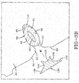
FIG. 3B illustrates a round pump tube that has been inserted in the tire ofFig. 2 . -
FIG. 3C illustrates a close up cross-sectional view of the end cap inserted over the opening of the round pump tube. -
FIG. 3D illustrates a close up cross-sectional view of the pump tube after assembly into the pump sidewall passageway. -
FIG. 4A illustrates a close up cross-sectional view of the pump tube in the pump sidewall passageway under load and in the open position. -
FIG. 4B illustrates a close up cross-sectional view of the pump tube in the pump sidewall passageway under load and in the closed position. - Referring to
FIGS. 1 and2 , atire assembly 10 is shown including atire 12. The tire comprises aperistaltic pump assembly 14. Also atire wheel 16 is shown. The tire mounts in conventional fashion to thewheel 16. Thewheel 16 has arim 28 withrim mounting flanges 26. The tire is preferably of conventional construction, having a pair ofsidewalls 32 extending fromopposite bead areas 34 to a crown or tire readregion 38. Thetire 12 has atire cavity 40 which is enclosed by thetire 12 and therim 28. - As shown in
Figs. 1 ,2 and3 , thepump assembly 14 includes anair tube 50 mounted in a passageway orgroove 60. Thetube 50 is formed of a resilient, flexible material such as plastic or rubber compounds that are capable of withstanding repeated deformation cycles. So constructed, the tube may deform within a tire into a flattened condition subject to external force and, upon removal of such force, return to an original sectional configuration. In the embodiment shown, the cross-section of thetube 50 in an unstressed state is generally circular with an innerround hole 52 formed by thetube wall 54. - The
tube 50 is of a diameter sufficient to operatively pass a requisite volume of air sufficient for the purpose of pumping air into thetire cavity 40 to maintain thetire 12 at a preferred inflation pressure. - While the
air tube 50 shown in this embodiment is annular for a 360 degree pump, the air tube need not be annular and may have any sufficient length for example, a 180 degree pump. - As shown in
Figs. 1 and2 , theperistaltic pump assembly 14 may further include aregulator device 70 and an air intake andfilter assembly 75. Theregulator device 70 functions to prevent air from entering the peristaltic pump through the air intake andfilter assembly 75 if the tire air pressure incavity 40 of the tire is greater than a selectable set point pressure. If the tire cavity pressure is below the set point pressure, theregulator 70 opens an air passage connected to the pump inlet of the peristaltic pump to allow outside air to flow into the peristaltic pump. The regulator may be as described inWO-A-2015/105848 , which is hereby incorporated by reference. - As the tire rotates, the sidewall of the tire undergoes compression as it enters the tire footprint. A compressive force 104 is directed into the tire from the footprint 100 and acts to flatten a portion of the air tube passageway as shown in
Fig. 4B . As the tire continues to rotate, the pump tube will be sequentially flattened or squeezed opposite the tire footprint in a segment by segment manner in a direction opposite to the direction of tire rotation. The sequential flattening of thetube passageway 50 segment by segment causes evacuated air from the flattened segments to be pumped to the outlet, into the regulator device and then into thetire cavity 40. In addition, as the tire rotates, the flattened tube segments are refilled with air from the airintake filter assembly 75 until the regulator shuts off flow to the pump when the set pressure is reached. - A preferred location for the
air tube assembly 14 is as shown inFig. 2 . Theair tube assembly 14 is preferably mounted in an area of the tire that undergoes bending strain. Utilizing the bending strain within a bending region of a sidewall avoids the need to compress the air tube by pinching the air tube against a relatively hard barrier such as the tire assembly rim. Potential damage to the air tube from contact with the rim is thus avoided and the structural integrity of the air tube is preserved throughout the life cycle of the tire. Thetube 50 is located within agroove 60. Thegroove 60 is preferably located in thelower sidewall 32 of thetire 12, and more preferably, in the lower sidewall area radially outward of the upper rim flange when mounted on a wheel, as shown inFig. 2 , where bending deformation of the tire helps to achieve tube pinching. - The
tube 50 is closed by compression strain bending thegroove 60 within a rolling tire footprint. The location of thetube 50 in the sidewall 30 affords the user freedom of placement and avoids contact between thetube 50 and therim flange 26. The higher placement of thetube 50 in thegroove 60 uses the deformation of the sidewall as it passes through the tire footprint to close the tube. - The
groove 60 is shown in an unloaded state inFig. 3A. Fig. 3A illustrates the tube in phantom positioned within thegroove 60. Thetube 50 has a diameter D greater than the width of thegroove 60, such that there is an interference fit of thetube 50 in the width direction, when thetube 50 is mounted in thegroove 60. Thegroove 60 has a length L that is in the range of from 2 to 4 times the width W, and more preferably in the range of from 3 to 4 times the width W. The outside diameter D of thetube 50 is preferably greater than the width W of the groove, and more preferably in the range of from 1.5 to 2 times the width W of the groove. The length of the groove L is greater than the outside diameter D of thetube 50, so that when the tube is inserted in thegroove 60, thetube 50 does not fill theentire groove 60 leaving agap 110. Thegap 110 allows room for filing theentire groove 60 with an adhesive to secure the tube within the groove. Thus, with respect to the groove length, the tube does not have an interference fit with respect to the groove length. Thegroove 60 further includes aneck portion 65 with a reduced width N located at the groove inlet. The reduced width N is in the range of 40-60% of the width W. Thegroove 60 is defined by a first andsecond sidewalls second sidewalls terminal end 64 of thegroove 60. - After the
tube 50 is inserted into thegroove 60, acoverstrip 130 may be inserted into the groove inlet to secure the tube inside the tire. Thecoverstrip 130 preferably has a circular recessedface 132 that is positioned against the curvedouter surface 51 of thetube 50. Thecoverstrip 130 preferably has two opposedneck portions groove neck 65. Thecoverstrip 130 preferably hasouter end portions beveled portion 69 of thegroove 60.Fig 3D illustrates the tube and groove in the assembled position when the tire is in an unloaded state. When the tube is mounted into the groove, the tube cross-sectional shape is generally elliptical.Fig. 4A illustrates the groove and tube assembly when the tire is rotating under load, showing the tube in the open position.Fig. 4B illustrates when the groove and tube assembly has rotated into the footprint area, so that thetire sidewall 32 is under compression, and thetube 52 is in the closed position.
Claims (15)
- A self-inflating tire having a tire cavity (40), first and second sidewalls (32) extending respectively from first and second tire bead regions (34) to a tire tread region, a groove or passageway (60) positioned within the tire (12), and a tube (50) positioned within the groove or passageway (60), wherein the tube (50) has a circular cross-sectional shape and has an outside diameter D, wherein the groove or passageway (60) does not have a circular cross-sectional shape and has a width W and a length L, and wherein D is greater than W.
- The tire of claim 1, wherein D is less than L.
- The tire of claim 1 or 2, wherein the groove or passageway (60) is positioned in the tire sidewall (32) or in the lower end of the tire sidewall (32).
- The tire of at least one of the previous claims wherein the tube (50) is annular.
- The tire of at least one of the previous claims wherein the groove or passageway (50) is located proximally above the upper boundary of a rim (28) when the tire (12) is mounted to a rim.
- The tire of at least one of the previous claims wherein the tube cross-sectional shape is generally elliptical when mounted in the groove or passageway in the tire unloaded state.
- The tire of at least one of the previous claims wherein the groove or passageway narrows toward its opening or axially outer end.
- The tire of at least one of the previous claims wherein the groove or passageway (60) narrows toward its terminal end or axially inner end.
- The tire of at least one of the previous claims wherein the groove or passageway (60) has a length L that is in the range of 2 to 4 times or 3 to 4 times its width W.
- The tire of at least one of the previous claims wherein the outside diameter D of the tube or passageway is in the range of 1.5 to 2 time its width W.
- The tire of at least one of the previous claims wherein tube (50) is part of a peristaltic pump assembly (14) and is in fluid communication with the tire cavity (40) for self-inflation of the tire when the tire is rolling under load.
- The tire of at least one of the previous claims wherein the peristaltic pump assembly (14) comprises a regulator device (70) and an air intake assembly (75), the air intake assembly optionally further comprising a filter.
- The tire of at least one of the previous claims wherein the tube (50) does not fill the entire groove or passageway (60) leaving a gap (110).
- The tire of claim 13 wherein the gap (110) comprises or is filled with an adhesive.
- The tire of at least one of the previous claims wherein a coverstrip (130) is inserted into the inlet of the groove or passageway (60) to secure the tube (50), the coverstrip preferably having a circular recessed face (132) positioned against a curved outer surface (51) of the tube (50).
Applications Claiming Priority (1)
| Application Number | Priority Date | Filing Date | Title |
|---|---|---|---|
| US14/567,446 US10239368B2 (en) | 2014-12-11 | 2014-12-11 | Air maintenance tire and valve assembly |
Publications (2)
| Publication Number | Publication Date |
|---|---|
| EP3031633A1 true EP3031633A1 (en) | 2016-06-15 |
| EP3031633B1 EP3031633B1 (en) | 2017-08-16 |
Family
ID=54770944
Family Applications (1)
| Application Number | Title | Priority Date | Filing Date |
|---|---|---|---|
| EP15197289.0A Not-in-force EP3031633B1 (en) | 2014-12-11 | 2015-12-01 | Air maintenance tire and valve assembly |
Country Status (4)
| Country | Link |
|---|---|
| US (1) | US10239368B2 (en) |
| EP (1) | EP3031633B1 (en) |
| CN (1) | CN105691123A (en) |
| BR (1) | BR102015030390A2 (en) |
Cited By (1)
| Publication number | Priority date | Publication date | Assignee | Title |
|---|---|---|---|---|
| EP3318429A1 (en) * | 2016-11-08 | 2018-05-09 | The Goodyear Tire & Rubber Company | Air maintenance tire |
Citations (4)
| Publication number | Priority date | Publication date | Assignee | Title |
|---|---|---|---|---|
| EP2338703A2 (en) | 2009-12-21 | 2011-06-29 | The Goodyear Tire & Rubber Company | Self-inflating tire assembly |
| EP2543524A1 (en) * | 2011-07-08 | 2013-01-09 | The Goodyear Tire & Rubber Company | Air maintenance pumping assembly and tire |
| EP2777959A1 (en) * | 2013-03-15 | 2014-09-17 | The Goodyear Tire & Rubber Company | Tire with groove containing bonded tube and mehood of manufacturing |
| WO2015105848A2 (en) | 2014-01-07 | 2015-07-16 | Eaton Corporation | Self-inflating tire air regulator |
Family Cites Families (6)
| Publication number | Priority date | Publication date | Assignee | Title |
|---|---|---|---|---|
| KR20130058658A (en) | 2010-04-16 | 2013-06-04 | 아사히 가라스 가부시키가이샤 | Fluorine-containing copolymer composition and production method for same |
| US20130061996A1 (en) * | 2011-09-08 | 2013-03-14 | Andres Ignacio Delgado | Air maintenance pumping assembly and tire |
| US8944126B2 (en) * | 2012-07-30 | 2015-02-03 | The Goodyear Tire & Rubber Company | Filter for a pneumatic tire |
| US8960249B2 (en) * | 2012-10-15 | 2015-02-24 | The Goodyear Tire & Rubber Company | Self-inflating tire |
| US9199518B2 (en) * | 2012-10-24 | 2015-12-01 | The Goodyear Tire & Rubber Company | Method of assemblying a segmented vein air pump in a tire |
| US9533533B2 (en) * | 2014-04-24 | 2017-01-03 | The Goodyear Tire & Rubber Company | Vein-style air pumping tube and tire system and method of assembly |
-
2014
- 2014-12-11 US US14/567,446 patent/US10239368B2/en active Active
-
2015
- 2015-12-01 EP EP15197289.0A patent/EP3031633B1/en not_active Not-in-force
- 2015-12-03 BR BR102015030390A patent/BR102015030390A2/en not_active Application Discontinuation
- 2015-12-11 CN CN201510912596.7A patent/CN105691123A/en active Pending
Patent Citations (4)
| Publication number | Priority date | Publication date | Assignee | Title |
|---|---|---|---|---|
| EP2338703A2 (en) | 2009-12-21 | 2011-06-29 | The Goodyear Tire & Rubber Company | Self-inflating tire assembly |
| EP2543524A1 (en) * | 2011-07-08 | 2013-01-09 | The Goodyear Tire & Rubber Company | Air maintenance pumping assembly and tire |
| EP2777959A1 (en) * | 2013-03-15 | 2014-09-17 | The Goodyear Tire & Rubber Company | Tire with groove containing bonded tube and mehood of manufacturing |
| WO2015105848A2 (en) | 2014-01-07 | 2015-07-16 | Eaton Corporation | Self-inflating tire air regulator |
Cited By (3)
| Publication number | Priority date | Publication date | Assignee | Title |
|---|---|---|---|---|
| EP3318429A1 (en) * | 2016-11-08 | 2018-05-09 | The Goodyear Tire & Rubber Company | Air maintenance tire |
| US20180126799A1 (en) * | 2016-11-08 | 2018-05-10 | The Goodyear Tire & Rubber Company | Air maintenance tire |
| US10773559B2 (en) | 2016-11-08 | 2020-09-15 | The Goodyear Tire & Rubber Company | Air maintenance tire |
Also Published As
| Publication number | Publication date |
|---|---|
| CN105691123A (en) | 2016-06-22 |
| EP3031633B1 (en) | 2017-08-16 |
| US10239368B2 (en) | 2019-03-26 |
| US20160167457A1 (en) | 2016-06-16 |
| BR102015030390A2 (en) | 2016-08-23 |
Similar Documents
| Publication | Publication Date | Title |
|---|---|---|
| EP2565061B1 (en) | Self-inflating tire and pressure regulator device | |
| EP2565060B1 (en) | Self-inflating tire | |
| EP2433822B1 (en) | Distributed pump self-inflating tire assembly | |
| EP2565059B1 (en) | Pneumatic tire | |
| EP2338703B1 (en) | Self-inflating tire assembly | |
| EP2746073B1 (en) | Compact valve system for a self-inflating tire | |
| EP2746072B1 (en) | Compact valve system for self-inflating tire | |
| EP2719553A2 (en) | Self-inflating tire assembly | |
| EP2384912A1 (en) | Self-inflating tire assembly | |
| US9796224B2 (en) | Valve stem-based air maintenance tire and method | |
| EP2578420B1 (en) | Tire comprising a tube assembly and method of assembling an elongate air tube within a tire | |
| EP2343200A2 (en) | Self-inflating tire | |
| EP2746075A2 (en) | Compact valve system for self-inflating tire | |
| EP2886374B1 (en) | Self-inflatng tire with pressure regulator | |
| US9796223B2 (en) | Valve stem-based air maintenance tire and method | |
| EP2740616A1 (en) | Air maintenance pumping assembly and tire | |
| EP3130487A1 (en) | Valve stem-based air maintenance tire and method | |
| EP3199386B1 (en) | Valve stem-based air maintenance tire and method | |
| EP2810798B1 (en) | Distributed cavity air pumping assembly and method for a tire | |
| EP2883718B1 (en) | Self-inflating tire with hybrid pump | |
| EP2886375A2 (en) | Self inflating tire with pressure regulator | |
| EP3031633B1 (en) | Air maintenance tire and valve assembly | |
| EP3332994A1 (en) | Air maintenance tire and valve assembly and method | |
| EP3170684B1 (en) | Valve stem-based air maintenance tire and method | |
| EP2746071B1 (en) | Pneumatic tire |
Legal Events
| Date | Code | Title | Description |
|---|---|---|---|
| PUAI | Public reference made under article 153(3) epc to a published international application that has entered the european phase |
Free format text: ORIGINAL CODE: 0009012 |
|
| AK | Designated contracting states |
Kind code of ref document: A1 Designated state(s): AL AT BE BG CH CY CZ DE DK EE ES FI FR GB GR HR HU IE IS IT LI LT LU LV MC MK MT NL NO PL PT RO RS SE SI SK SM TR |
|
| AX | Request for extension of the european patent |
Extension state: BA ME |
|
| 17P | Request for examination filed |
Effective date: 20161215 |
|
| RBV | Designated contracting states (corrected) |
Designated state(s): AL AT BE BG CH CY CZ DE DK EE ES FI FR GB GR HR HU IE IS IT LI LT LU LV MC MK MT NL NO PL PT RO RS SE SI SK SM TR |
|
| GRAP | Despatch of communication of intention to grant a patent |
Free format text: ORIGINAL CODE: EPIDOSNIGR1 |
|
| INTG | Intention to grant announced |
Effective date: 20170314 |
|
| GRAS | Grant fee paid |
Free format text: ORIGINAL CODE: EPIDOSNIGR3 |
|
| GRAA | (expected) grant |
Free format text: ORIGINAL CODE: 0009210 |
|
| AK | Designated contracting states |
Kind code of ref document: B1 Designated state(s): AL AT BE BG CH CY CZ DE DK EE ES FI FR GB GR HR HU IE IS IT LI LT LU LV MC MK MT NL NO PL PT RO RS SE SI SK SM TR |
|
| REG | Reference to a national code |
Ref country code: GB Ref legal event code: FG4D |
|
| REG | Reference to a national code |
Ref country code: CH Ref legal event code: EP |
|
| REG | Reference to a national code |
Ref country code: IE Ref legal event code: FG4D |
|
| REG | Reference to a national code |
Ref country code: AT Ref legal event code: REF Ref document number: 918681 Country of ref document: AT Kind code of ref document: T Effective date: 20170915 |
|
| REG | Reference to a national code |
Ref country code: DE Ref legal event code: R096 Ref document number: 602015004154 Country of ref document: DE |
|
| REG | Reference to a national code |
Ref country code: NL Ref legal event code: MP Effective date: 20170816 Ref country code: FR Ref legal event code: PLFP Year of fee payment: 3 |
|
| REG | Reference to a national code |
Ref country code: LT Ref legal event code: MG4D |
|
| REG | Reference to a national code |
Ref country code: AT Ref legal event code: MK05 Ref document number: 918681 Country of ref document: AT Kind code of ref document: T Effective date: 20170816 |
|
| PG25 | Lapsed in a contracting state [announced via postgrant information from national office to epo] |
Ref country code: NL Free format text: LAPSE BECAUSE OF FAILURE TO SUBMIT A TRANSLATION OF THE DESCRIPTION OR TO PAY THE FEE WITHIN THE PRESCRIBED TIME-LIMIT Effective date: 20170816 Ref country code: LT Free format text: LAPSE BECAUSE OF FAILURE TO SUBMIT A TRANSLATION OF THE DESCRIPTION OR TO PAY THE FEE WITHIN THE PRESCRIBED TIME-LIMIT Effective date: 20170816 Ref country code: AT Free format text: LAPSE BECAUSE OF FAILURE TO SUBMIT A TRANSLATION OF THE DESCRIPTION OR TO PAY THE FEE WITHIN THE PRESCRIBED TIME-LIMIT Effective date: 20170816 Ref country code: NO Free format text: LAPSE BECAUSE OF FAILURE TO SUBMIT A TRANSLATION OF THE DESCRIPTION OR TO PAY THE FEE WITHIN THE PRESCRIBED TIME-LIMIT Effective date: 20171116 Ref country code: SE Free format text: LAPSE BECAUSE OF FAILURE TO SUBMIT A TRANSLATION OF THE DESCRIPTION OR TO PAY THE FEE WITHIN THE PRESCRIBED TIME-LIMIT Effective date: 20170816 Ref country code: FI Free format text: LAPSE BECAUSE OF FAILURE TO SUBMIT A TRANSLATION OF THE DESCRIPTION OR TO PAY THE FEE WITHIN THE PRESCRIBED TIME-LIMIT Effective date: 20170816 |
|
| PGFP | Annual fee paid to national office [announced via postgrant information from national office to epo] |
Ref country code: FR Payment date: 20171220 Year of fee payment: 3 |
|
| PG25 | Lapsed in a contracting state [announced via postgrant information from national office to epo] |
Ref country code: IS Free format text: LAPSE BECAUSE OF FAILURE TO SUBMIT A TRANSLATION OF THE DESCRIPTION OR TO PAY THE FEE WITHIN THE PRESCRIBED TIME-LIMIT Effective date: 20171216 Ref country code: PL Free format text: LAPSE BECAUSE OF FAILURE TO SUBMIT A TRANSLATION OF THE DESCRIPTION OR TO PAY THE FEE WITHIN THE PRESCRIBED TIME-LIMIT Effective date: 20170816 Ref country code: RS Free format text: LAPSE BECAUSE OF FAILURE TO SUBMIT A TRANSLATION OF THE DESCRIPTION OR TO PAY THE FEE WITHIN THE PRESCRIBED TIME-LIMIT Effective date: 20170816 Ref country code: BG Free format text: LAPSE BECAUSE OF FAILURE TO SUBMIT A TRANSLATION OF THE DESCRIPTION OR TO PAY THE FEE WITHIN THE PRESCRIBED TIME-LIMIT Effective date: 20171116 Ref country code: ES Free format text: LAPSE BECAUSE OF FAILURE TO SUBMIT A TRANSLATION OF THE DESCRIPTION OR TO PAY THE FEE WITHIN THE PRESCRIBED TIME-LIMIT Effective date: 20170816 Ref country code: GR Free format text: LAPSE BECAUSE OF FAILURE TO SUBMIT A TRANSLATION OF THE DESCRIPTION OR TO PAY THE FEE WITHIN THE PRESCRIBED TIME-LIMIT Effective date: 20171117 Ref country code: LV Free format text: LAPSE BECAUSE OF FAILURE TO SUBMIT A TRANSLATION OF THE DESCRIPTION OR TO PAY THE FEE WITHIN THE PRESCRIBED TIME-LIMIT Effective date: 20170816 |
|
| PG25 | Lapsed in a contracting state [announced via postgrant information from national office to epo] |
Ref country code: CZ Free format text: LAPSE BECAUSE OF FAILURE TO SUBMIT A TRANSLATION OF THE DESCRIPTION OR TO PAY THE FEE WITHIN THE PRESCRIBED TIME-LIMIT Effective date: 20170816 Ref country code: DK Free format text: LAPSE BECAUSE OF FAILURE TO SUBMIT A TRANSLATION OF THE DESCRIPTION OR TO PAY THE FEE WITHIN THE PRESCRIBED TIME-LIMIT Effective date: 20170816 Ref country code: RO Free format text: LAPSE BECAUSE OF FAILURE TO SUBMIT A TRANSLATION OF THE DESCRIPTION OR TO PAY THE FEE WITHIN THE PRESCRIBED TIME-LIMIT Effective date: 20170816 |
|
| PGFP | Annual fee paid to national office [announced via postgrant information from national office to epo] |
Ref country code: DE Payment date: 20171229 Year of fee payment: 3 |
|
| REG | Reference to a national code |
Ref country code: DE Ref legal event code: R097 Ref document number: 602015004154 Country of ref document: DE |
|
| PG25 | Lapsed in a contracting state [announced via postgrant information from national office to epo] |
Ref country code: SM Free format text: LAPSE BECAUSE OF FAILURE TO SUBMIT A TRANSLATION OF THE DESCRIPTION OR TO PAY THE FEE WITHIN THE PRESCRIBED TIME-LIMIT Effective date: 20170816 Ref country code: SK Free format text: LAPSE BECAUSE OF FAILURE TO SUBMIT A TRANSLATION OF THE DESCRIPTION OR TO PAY THE FEE WITHIN THE PRESCRIBED TIME-LIMIT Effective date: 20170816 Ref country code: EE Free format text: LAPSE BECAUSE OF FAILURE TO SUBMIT A TRANSLATION OF THE DESCRIPTION OR TO PAY THE FEE WITHIN THE PRESCRIBED TIME-LIMIT Effective date: 20170816 |
|
| PLBE | No opposition filed within time limit |
Free format text: ORIGINAL CODE: 0009261 |
|
| STAA | Information on the status of an ep patent application or granted ep patent |
Free format text: STATUS: NO OPPOSITION FILED WITHIN TIME LIMIT |
|
| 26N | No opposition filed |
Effective date: 20180517 |
|
| PG25 | Lapsed in a contracting state [announced via postgrant information from national office to epo] |
Ref country code: SI Free format text: LAPSE BECAUSE OF FAILURE TO SUBMIT A TRANSLATION OF THE DESCRIPTION OR TO PAY THE FEE WITHIN THE PRESCRIBED TIME-LIMIT Effective date: 20170816 |
|
| REG | Reference to a national code |
Ref country code: IE Ref legal event code: MM4A |
|
| PG25 | Lapsed in a contracting state [announced via postgrant information from national office to epo] |
Ref country code: LU Free format text: LAPSE BECAUSE OF NON-PAYMENT OF DUE FEES Effective date: 20171201 Ref country code: MT Free format text: LAPSE BECAUSE OF NON-PAYMENT OF DUE FEES Effective date: 20171201 |
|
| REG | Reference to a national code |
Ref country code: BE Ref legal event code: MM Effective date: 20171231 |
|
| PG25 | Lapsed in a contracting state [announced via postgrant information from national office to epo] |
Ref country code: IE Free format text: LAPSE BECAUSE OF NON-PAYMENT OF DUE FEES Effective date: 20171201 |
|
| PG25 | Lapsed in a contracting state [announced via postgrant information from national office to epo] |
Ref country code: BE Free format text: LAPSE BECAUSE OF NON-PAYMENT OF DUE FEES Effective date: 20171231 |
|
| PGFP | Annual fee paid to national office [announced via postgrant information from national office to epo] |
Ref country code: IT Payment date: 20181231 Year of fee payment: 4 |
|
| PG25 | Lapsed in a contracting state [announced via postgrant information from national office to epo] |
Ref country code: MC Free format text: LAPSE BECAUSE OF FAILURE TO SUBMIT A TRANSLATION OF THE DESCRIPTION OR TO PAY THE FEE WITHIN THE PRESCRIBED TIME-LIMIT Effective date: 20170816 Ref country code: HU Free format text: LAPSE BECAUSE OF FAILURE TO SUBMIT A TRANSLATION OF THE DESCRIPTION OR TO PAY THE FEE WITHIN THE PRESCRIBED TIME-LIMIT; INVALID AB INITIO Effective date: 20151201 |
|
| REG | Reference to a national code |
Ref country code: DE Ref legal event code: R119 Ref document number: 602015004154 Country of ref document: DE |
|
| REG | Reference to a national code |
Ref country code: CH Ref legal event code: PL |
|
| PG25 | Lapsed in a contracting state [announced via postgrant information from national office to epo] |
Ref country code: CY Free format text: LAPSE BECAUSE OF FAILURE TO SUBMIT A TRANSLATION OF THE DESCRIPTION OR TO PAY THE FEE WITHIN THE PRESCRIBED TIME-LIMIT Effective date: 20170816 Ref country code: DE Free format text: LAPSE BECAUSE OF NON-PAYMENT OF DUE FEES Effective date: 20190702 Ref country code: FR Free format text: LAPSE BECAUSE OF NON-PAYMENT OF DUE FEES Effective date: 20181231 |
|
| PG25 | Lapsed in a contracting state [announced via postgrant information from national office to epo] |
Ref country code: MK Free format text: LAPSE BECAUSE OF FAILURE TO SUBMIT A TRANSLATION OF THE DESCRIPTION OR TO PAY THE FEE WITHIN THE PRESCRIBED TIME-LIMIT Effective date: 20170816 |
|
| PG25 | Lapsed in a contracting state [announced via postgrant information from national office to epo] |
Ref country code: LI Free format text: LAPSE BECAUSE OF NON-PAYMENT OF DUE FEES Effective date: 20181231 Ref country code: CH Free format text: LAPSE BECAUSE OF NON-PAYMENT OF DUE FEES Effective date: 20181231 |
|
| PG25 | Lapsed in a contracting state [announced via postgrant information from national office to epo] |
Ref country code: TR Free format text: LAPSE BECAUSE OF FAILURE TO SUBMIT A TRANSLATION OF THE DESCRIPTION OR TO PAY THE FEE WITHIN THE PRESCRIBED TIME-LIMIT Effective date: 20170816 |
|
| PG25 | Lapsed in a contracting state [announced via postgrant information from national office to epo] |
Ref country code: PT Free format text: LAPSE BECAUSE OF FAILURE TO SUBMIT A TRANSLATION OF THE DESCRIPTION OR TO PAY THE FEE WITHIN THE PRESCRIBED TIME-LIMIT Effective date: 20170816 |
|
| PG25 | Lapsed in a contracting state [announced via postgrant information from national office to epo] |
Ref country code: HR Free format text: LAPSE BECAUSE OF FAILURE TO SUBMIT A TRANSLATION OF THE DESCRIPTION OR TO PAY THE FEE WITHIN THE PRESCRIBED TIME-LIMIT Effective date: 20170816 |
|
| PG25 | Lapsed in a contracting state [announced via postgrant information from national office to epo] |
Ref country code: AL Free format text: LAPSE BECAUSE OF FAILURE TO SUBMIT A TRANSLATION OF THE DESCRIPTION OR TO PAY THE FEE WITHIN THE PRESCRIBED TIME-LIMIT Effective date: 20170816 |
|
| GBPC | Gb: european patent ceased through non-payment of renewal fee |
Effective date: 20191201 |
|
| PG25 | Lapsed in a contracting state [announced via postgrant information from national office to epo] |
Ref country code: GB Free format text: LAPSE BECAUSE OF NON-PAYMENT OF DUE FEES Effective date: 20191201 Ref country code: IT Free format text: LAPSE BECAUSE OF NON-PAYMENT OF DUE FEES Effective date: 20191201 |