EP3031628A1 - Fahrzeugluftreifen - Google Patents
Fahrzeugluftreifen Download PDFInfo
- Publication number
- EP3031628A1 EP3031628A1 EP15186362.8A EP15186362A EP3031628A1 EP 3031628 A1 EP3031628 A1 EP 3031628A1 EP 15186362 A EP15186362 A EP 15186362A EP 3031628 A1 EP3031628 A1 EP 3031628A1
- Authority
- EP
- European Patent Office
- Prior art keywords
- spike
- pneumatic vehicle
- vehicle tire
- tire according
- depth
- Prior art date
- Legal status (The legal status is an assumption and is not a legal conclusion. Google has not performed a legal analysis and makes no representation as to the accuracy of the status listed.)
- Granted
Links
Images


Classifications
-
- B—PERFORMING OPERATIONS; TRANSPORTING
- B60—VEHICLES IN GENERAL
- B60C—VEHICLE TYRES; TYRE INFLATION; TYRE CHANGING; CONNECTING VALVES TO INFLATABLE ELASTIC BODIES IN GENERAL; DEVICES OR ARRANGEMENTS RELATED TO TYRES
- B60C11/00—Tyre tread bands; Tread patterns; Anti-skid inserts
- B60C11/14—Anti-skid inserts, e.g. vulcanised into the tread band
- B60C11/16—Anti-skid inserts, e.g. vulcanised into the tread band of plug form, e.g. made from metal, textile
-
- B—PERFORMING OPERATIONS; TRANSPORTING
- B60—VEHICLES IN GENERAL
- B60C—VEHICLE TYRES; TYRE INFLATION; TYRE CHANGING; CONNECTING VALVES TO INFLATABLE ELASTIC BODIES IN GENERAL; DEVICES OR ARRANGEMENTS RELATED TO TYRES
- B60C11/00—Tyre tread bands; Tread patterns; Anti-skid inserts
- B60C11/03—Tread patterns
- B60C11/032—Patterns comprising isolated recesses
-
- B—PERFORMING OPERATIONS; TRANSPORTING
- B60—VEHICLES IN GENERAL
- B60C—VEHICLE TYRES; TYRE INFLATION; TYRE CHANGING; CONNECTING VALVES TO INFLATABLE ELASTIC BODIES IN GENERAL; DEVICES OR ARRANGEMENTS RELATED TO TYRES
- B60C11/00—Tyre tread bands; Tread patterns; Anti-skid inserts
- B60C11/03—Tread patterns
- B60C11/11—Tread patterns in which the raised area of the pattern consists only of isolated elements, e.g. blocks
-
- B—PERFORMING OPERATIONS; TRANSPORTING
- B60—VEHICLES IN GENERAL
- B60C—VEHICLE TYRES; TYRE INFLATION; TYRE CHANGING; CONNECTING VALVES TO INFLATABLE ELASTIC BODIES IN GENERAL; DEVICES OR ARRANGEMENTS RELATED TO TYRES
- B60C11/00—Tyre tread bands; Tread patterns; Anti-skid inserts
- B60C11/14—Anti-skid inserts, e.g. vulcanised into the tread band
- B60C11/16—Anti-skid inserts, e.g. vulcanised into the tread band of plug form, e.g. made from metal, textile
- B60C11/1625—Arrangements thereof in the tread patterns, e.g. irregular
Definitions
- the invention relates to a pneumatic vehicle tire with a tread with by grooves, such as circumferential grooves, oblique grooves, transverse grooves, separate profile positive, such as tread blocks, each having a surface coming into contact with the surface, wherein profile positive are provided in which at least one spike with his Spike body is anchored in the rubber material of the profile positive, wherein the spike has a spike pin which protrudes in the radial direction of the spike body and projects beyond the surface of the profile positive, the spike at least one trained in profile positive as a drain channel for receiving the scratching of the spike on ice associated with the resulting ice chips.
- profile positive are provided in which at least one spike with his Spike body is anchored in the rubber material of the profile positive, wherein the spike has a spike pin which protrudes in the radial direction of the spike body and projects beyond the surface of the profile positive, the spike at least one trained in profile positive as a drain channel for receiving the scratching of the spike on ice associated with the resulting ice chips.
- a pneumatic vehicle tire of the aforementioned type which has a recess for receiving the scrap of ice scraped off the icy ground by the spikes, wherein the recess surrounds the spike in a substantially annular manner is known from US Pat EP 2 501 562 B1 known.
- the recession surrounding the spike does not allow the targeted dissipation of the ice chips formed by the scratching of the spike, but even promotes the emergence of flow movements of the splinters in the depression, so that a discharge is disturbed and hindered.
- the annular circumferential recess would also have to be made at a depth that ensures a good absorption of the ice chips, which, however, without jeopardizing the embedding of the spike is not possible.
- a pneumatic vehicle tire is known in which drainage channels are provided, which are formed as pronounced grooves on the surface of the profile positive and open into a respective profile positive limiting groove. From this groove can therefore snow and ice shards through the gutter be directed towards spike and therefore hinder the removal of scraped by the spike from the ground ice fragments, in the worst case, even the gutter can be blocked.
- the spike straight or curved recesses in the surface of the profile positive which are also not suitable from their orientation and execution, to ensure a good dissipation of scraped by the spike from the ground ice chips.
- the depressions largely run with a width and depth that could jeopardize the anchoring of the spikes in the profile positive.
- the invention is based on the object to provide in a tire of the type mentioned Ableitkanäle for scraped by the spike from the ground ice chips available that ensure optimal routing of the ice chips from the spike and do not jeopardize the anchoring of the spike body in the rubber material of the profile positive ,
- the object is achieved according to the invention in that is provided at the circumferentially opposite sides of the spike body immediately at this starting ever a discharge channel, which ends within the respective profile positive, each discharge a running over most of its longitudinal main section, in which the Width and increase the depth of the discharge channel with increasing distance from the spike body, and then has an end portion in which the depth and the width of the discharge channel decrease with increasing distance from the spike body.
- two Ableitkanäle are provided, which, viewed in the braking and traction direction (when driving forward), are arranged immediately in front of and behind the spike.
- the ice chips formed by the spike can therefore be removed without resistance and without having to change their direction.
- the depth and the width of the discharge channel increase again, stabilizes the profile positive in this area, which is especially important if there runs a transversely extending profile positive edge.
- the stabilization prevents unwanted "folding” or “curling” of this edge when rolling the tire.
- the invention therefore ensures that a sufficiently wide and deep reservoir is available for the ice chips removal, whereby the rubber material required for spike embedding, which supports the spike and prevents tilting, is retained.
- the extension lengths of the drainage channels are 4 mm to 14 mm.
- the actual length of the drainage channels is matched to the position of the spikes in the profile positive and the available area in the profile positive.
- the one discharge channel have a length which differs from the length of the other discharge channel.
- the discharge channel arranged in front of the spike during forward travel is made longer than the other discharge channel. The greater the length of the drainage channels, the less resistance the resulting ice chips can be dissipated.
- the extension lengths of the main sections are in a further preferred embodiment of the invention substantially longer than the extension lengths of the end sections and in particular between 3 mm and 12 mm.
- the main sections immediately at the spike body, therefore at the spike edge have a width which corresponds to 0.5 to 1.5 times the axial width of the spike pin.
- the main sections are delimited on the surface of the profile positive by rectilinear boundary edges which extend under increasing their mutual distance in each case at an angle of 2 ° to 10 ° to the circumferential direction.
- an increasing volume in the direction away from the spike is provided for the ice chips with an optimized course.
- the depth of the main sections in the spike body 0.5 mm to 1.2 mm and increases continuously towards the end portions to a depth which is 1.05 times to 3.6 times the former depth.
- the end portions are carried out according to the invention such that they are bounded on the surface of the profile positive of boundary edges, which converge pointedly and together at an angle of 95 ° to 150 °, in particular from 110 ° to 130 °. Further preferably, the depth of the end portions at the intersection of their boundary edges is 0.4 to 2.4 times the depth of the main portions at the spike edge and is less than the largest depth of the main portions.
- This special design of the end sections stabilizes the profile positive in the region of the profile positive edge adjacent to the end section and the function of the profile positive or block edges as gripping edges can be fully maintained. It is advantageous if the minimum distance of the discharge channels of adjacent profile positive edges is 0.5 mm.
- the distance between the discharge channels and the secondary channels is 1 mm to 1.5 mm and, furthermore, if the secondary channels have a width of 1.5 mm to 2 over most of their extension, 2 mm, wherein this width can be continuously reduced over the extent of the secondary channels in the direction away from the spike.
- the secondary channels may also have a particular constant depth of 0.5 mm to 0.7 mm.
- the minimum distance of the secondary channels of adjacent profile positive edges is 0.4 mm.
- the secondary channels have extension lengths which are adapted to the extension lengths of the main channels, but the secondary channels can also be made shorter or longer than the discharge channels, their length being between 3 mm and 14 mm.
- FIGS. 1 to 5 each show schematically a plan view of a tread block 1 of a tread of a pneumatic vehicle tire, in particular a winter tire in radial design for passenger cars.
- the profile block 1 can on both sides of a circumferential groove in the circumferential direction of the tread, which is characterized by a double arrow, extending circumferential groove and each one of the profile block 1 upstream and downstream, in the axial direction ( Fig. 1 to Fig. 4 ) or at an acute angle to the axial direction ( Fig. 5 ) running transverse groove be limited.
- the actual outer shape of the tread blocks 1 may differ from the simplified illustrated, so that the intended grooves with respect to the circumferential and transverse directions can be arbitrarily oriented.
- Each profile block 1 can also be provided with a number of not shown, performed in a conventional manner incisions.
- the surface 1a of each profile block 1 forms the surface of the profile block 1 which comes into contact with the substrate when the tire rolls off.
- a spike 2 which is designed in particular in a manner known per se, is inserted and anchored with a spike body 3 and a spike pin 4 in a spike hole created during the vulcanization of the tire.
- the spike body 3 has a substantially cylindrical base part with a foot part 5 and a circular, planar surface 6.
- the Spikeloch is created such that the surface 6 is either flush with the surface 1a of the profile block 1 or slightly radially located within the surface 1a.
- the distance between the surface 6 and the surface 1a is only a few tenths of a millimeter, in particular about 0.3 mm.
- the spike pin 4 anchored in the spike body 3 extends in the radial direction into the spike body 3 and projects in a known manner over the surface 6 of the spike body 3, so that the surface 1a of the profile block 1 from the spike pin 4 by 0.4 mm to 2.0 mm, in particular by 1.0 mm, surmounted.
- the spike pin 4 is elongate or oval in plan view, wherein the spike 2 is preferably anchored in the tread or tread block 1 such that the greater extension of the spike pin 4 is present in the axial direction.
- the invention is based on the FIGS. 1 . 1a and 1b explained in detail below.
- the spike 2 is anchored.
- two Ableitkanäle 7, 8 is formed, wherein extending a discharge channel 7 in the one circumferential direction and the other discharge 8 in the other circumferential direction.
- Each discharge channel 7, 8 is symmetrical with respect to a symmetry plane S spanned by the circumferential direction and the radial direction and has a main section 9, 10 and an end section 11, 12.
- the main section 9, 10 has lateral boundary edges 9a, 10a on the surface 1a of the profile block 1, which extend at an acute angle ⁇ to the circumferential direction, which is 2 ° to 10 °, in particular 5 °, straight, wherein the mutual distance b of the boundary edges 9a, 10a increases with increasing distance from the spike 2.
- the mutual distance b of the boundary edges 9a, 10a corresponds to the width of the main sections 9, 10 and amounts to the spike edge 0.5 to 1.5 times the axial width b 'of the spike pin 4.
- the discharge channel 7 in the main portion 9 a bottom 9b and lateral flanks 9c, which extend between the bottom 9b and the lateral boundary edges 9a in the radial direction.
- the discharge channel 8 is designed in an analogous manner, its bottom 10 b in the main portion 10 is in Fig. 1a shown.
- the main sections 9, 10 of the Ableitkanäle 7, 8 have the spike 2 has a depth t 1 of 0.5 mm to 1.2 mm, in particular 0.8 mm to 1.0 mm.
- the embodiment can also be such that the main sections 9, 10 have a flat V-shaped bottom 9b, 10b in cross section, so that the greatest depth t 2 is present in the center of the bottom 9b, 10b, at the lateral flanks 9c, the depth t 2 slightly, by a maximum of 0.5 mm, in particular by a maximum of 0.3 mm, be less.
- t 2 is in particular 1.6 times the depth t 1
- t 2 is in particular 1.5 times the depth t 1 .
- the respective determined in the circumferential direction along the plane of symmetry S maximum lengths L 7 , L 8 of Ableitkanäle 7, 8 are adapted to the respective position of the spike 2 in the profile block 1 and the circumferential dimension of the profile block 1 and are 4 mm to 14 mm.
- the minimum distance a of the discharge channels 7, 8 from the transversely extending profile block edges 1b is 0.4 mm.
- the distance a is determined at a right angle to the extension of the relevant profile block edge 1 b between this and the location of the respective discharge channel 7, 8 closest thereto. In a preferred embodiment of the invention, the distance a is up to 1 mm, but may, depending on the configuration of the profile block 1, in which the spike 2 is positioned, also be substantially larger.
- the extension length L 9 , L 10 of the main sections 9, 10 along the plane of symmetry S is depending on the design and arrangement of the spikes 2 in the tread blocks 1 and depending on the design of the tread blocks 13 mm to 12 mm.
- the end portions 11, 12 of the Ableitkanäle 7, 8 are bounded on the surface 1 a of the profile block 1 each of two boundary edges 11 a, 12 a, the pointed converge and each other at an angle ⁇ of 95 ° to 150 °, in particular 110 ° to 130 °, preferably about 120 °, extend.
- the end sections 11, 12 each have a bottom 11b, 12b and flanks not visible in the figures, which run from the respective bottom 11b, 12b to the edges 11a, 12a in the radial direction.
- the discharge channels 7, 8 may differ in their extension lengths, it is advantageous if the shorter of the two drainage channels 7, 8 has a slightly greater depth than the longer one.
- a side channel 13, 14 runs on each side of the discharge channel 7, on each side of the discharge channel 8 a secondary channel 15, 16, each substantially parallel to the adjacent lateral boundary edge 9a, 10a of the main section 9, 10, at a distance c of 1 mm to 1.5 mm.
- a narrow, preferably in plan view designed as a circular ring portion rubber bridge 17 whose width d is 0.1 mm to 0.2 mm the secondary channels 13, 14, 15, 16 can also extend directly to the spike body 3.
- the second ends of the secondary channels 13, 14, 15, 16 are also located within the profile block 1, wherein the distance f of these ends of the secondary channels 13, 14, 15, 16 from the adjacent profile block edge 1b is at least 0.4 mm.
- the side channels 13, 14, 16, 16 have a U-shaped cross-section, their width e is, apart from their width immediately at their end portions in their course from the spike 2 away slightly larger and is 1.5 mm to 2.2 mm.
- the depth of the secondary channels 13, 14, 15, 16 is substantially constant over their extent and is 0.5 mm to 0.7 mm, in particular 0.6 mm.
- the circumferentially existing extension lengths L n of the secondary channels 13, 14, 15, 16 vary depending on the arrangement of the spike 2 in the profile block 1 and the embodiment or outer shape of the profile block 1 between 3 mm and 14 mm.
- Fig. 1 shows an embodiment in which the extension length L 7 of the discharge channel 7 is greater than the extension length L 8 of the discharge channel 8.
- the two next to the discharge channel 7 extending side channels 13, 14 have matching extension lengths L n and extend beyond the discharge channel 7 in the circumferential direction, here for example by about 0.5 mm.
- the two side channels 15, 16 extending next to the discharge channel 8 extend in the circumferential direction essentially as far as the discharge channel 8.
- FIGS. 2 to 6 Embodiments shown are variants of in Fig. 1 shown embodiment of the invention. There are therefore provided in these figures, mainly the Ableitkanäle 7, 8, the secondary channels 13, 14, 15, 16, the profile block 1 shown in each case and the spike 2 with reference numerals.
- Fig. 2 shows an embodiment in which the spike 2 is positioned slightly eccentrically in the profile block 1, so that the discharge channel 7 may have a greater extension length L 7 than the discharge channel 8 located opposite thereto.
- the two adjacent channels 13 extending next to the discharge channel 7 , 14 a slightly smaller extension length than the discharge channel 7, the two adjacent to the discharge channel 8 extending side channels 15, 16 are slightly longer than the discharge channel. 8
- Fig. 3 shows a variant in which the spike 2 is offset relatively far to the lower profile block edge 1b in this figure and therefore is positioned clearly off-center in the profile block 1.
- the discharge channel 7 has a more than twice the extension length L 7 as the discharge channel 8.
- the adjacent to the discharge channel 7 extending secondary channels 13, 14 are designed significantly shorter than the discharge channel 7, the side adjacent the discharge channel 8 arranged side channels 15, 16 have a slightly greater extension length than the discharge channel. 8
- Fig. 4 shows an embodiment of the invention in a tread block 1, the circumferential length is greater than its axial width.
- the discharge channels 7, 8 have a large Extension length L 7 , L 8, for example, 12 mm and are the same length here.
- the secondary channels 13, 14 and 15, 16 are shorter than the discharge channels 7, 8 and in this example the same length.
- the two drainage channels 7, 8, which have substantially equal extension lengths L 7 , L 8 , extend from the spike 2 positioned approximately centrally in the profile block 1.
- the two adjacent to the discharge channel 7 arranged side channels 13, 14 have different extension lengths, the in Fig. 5 left side of the discharge channel 7 extending side channel 13 is made shorter than the in Fig. 5 Right side of the discharge channel 7 extending side channel 14, which has 1 space due to the design of the profile block for a greater extension length available.
- This also applies to the adjacent to the discharge channel 8 adjacent channel 15, which in addition to this discharge 8 right-running auxiliary channel 16 is in turn made shorter.
- the extension length of the sub-channels 14, 16 can be adjusted accordingly.
- the spikes can also be positioned clearly outside the middle region of a profile positive.
Landscapes
- Engineering & Computer Science (AREA)
- Mechanical Engineering (AREA)
- Tires In General (AREA)
Abstract
Description
- Die Erfindung betrifft einen Fahrzeugluftreifen mit einem Laufstreifen mit durch Rillen, wie Umfangsrillen, Schrägrillen, Querrillen, voneinander getrennten Profilpositiven, wie Profilblöcken, die jeweils eine mit dem Untergrund in Kontakt kommende Oberfläche aufweisen, wobei Profilpositive vorgesehen sind, in welchen zumindest ein Spike mit seinem Spikekörper im Gummimaterial des Profilpositivs verankert ist, wobei der Spike einen Spikepin aufweist, der in radialer Richtung aus dem Spikekörper herausragt und die Oberfläche des Profilpositivs überragt, wobei dem Spike zumindest ein im Profilpositiv als Vertiefung ausgebildeter Ableitkanal zur Aufnahme der beim Kratzen des Spikes auf Eis entstehenden Eissplitter zugeordnet ist.
- Es ist bekannt, dass sich die Performance von Spikereifen auf eisigem Untergrund durch in der Nähe der Spikes im Profilpositiv ausgebildete Ableitkanäle bzw. Vertiefungen verbessern lässt. Ein Fahrzeugluftreifen der eingangs genannten Art, welcher eine Vertiefung zur Aufnahme der durch die Spikes vom eisigen Untergrund abgekratzten Eissplitter aufweist, wobei die Vertiefung den Spike im Wesentlichen ringförmig umschließt, ist aus der
EP 2 501 562 B1 bekannt. Die den Spike umlaufende Vertiefung erlaubt jedoch kein gezieltes Ableiten der durch das Kratzen des Spikes gebildeten Eissplitter, sondern fördert sogar das Entstehen von Fließbewegungen der Splitter in der Vertiefung, sodass ein Ableiten gestört und behindert wird. Die ringförmig umlaufende Vertiefung müsste ferner in einer Tiefe ausgeführt werden, die eine gute Aufnahme der Eissplitter sicherstellt, was jedoch, ohne die Einbettung des Spikes zu gefährden, nicht möglich ist. Aus derEP 2 285 599 B1 ist ein Fahrzeugluftreifen bekannt, bei dem Ableitkanäle vorgesehen sind, die als ausgeprägte Rinnen an der Oberfläche der Profilpositive ausgebildet sind und in eine das jeweilige Profilpositiv begrenzende Rille einmünden. Von dieser Rille aus können daher Schnee und auch Eissplitter durch die Rinne hindurch in Richtung Spike geleitet werden und daher den Abtransport der durch den Spike vom Untergrund abgekratzten Eissplitter behindern, wobei im schlimmsten Fall sogar die Rinne verstopft werden kann. Bei der aus derEP 2 285 600 B1 bekannten Ausführung sind beim Spike gerade oder gekrümmt verlaufende Vertiefungen in der Oberfläche des Profilpositivs ausgebildet, die von ihrer Ausrichtung und Ausführung her ebenfalls nicht dafür geeignet sind, für eine gute Ableitung der durch den Spike vom Untergrund abgekratzten Eissplitter zu sorgen. Insbesondere verlaufen die Vertiefungen großteils mit einer Breite und Tiefe, die die Verankerung der Spikes im Profilpositiv gefährden könnte. - Der Erfindung liegt die Aufgabe zu Grunde, bei einem Reifen der eingangs genannten Art Ableitkanäle für die durch den Spike vom Untergrund abgekratzten Eissplitter zur Verfügung zu stellen, die ein optimales Wegleiten der Eissplitter vom Spike gewährleisten und die Verankerung des Spikekörpers im Gummimaterial des Profilpositivs nicht gefährden.
- Gelöst wird die gestellte Aufgabe erfindungsgemäß dadurch, dass an den in Umfangsrichtung gegenüber befindlichen Seiten des Spikekörpers unmittelbar bei diesem beginnend je ein Ableitkanal vorgesehen ist, welcher innerhalb des jeweiligen Profilpositivs endet, wobei jeder Ableitkanal einen über den Großteil seiner Längserstreckung verlaufenden Hauptabschnitt, in welchem die Breite und die Tiefe des Ableitkanals mit zunehmender Entfernung vom Spikekörper zunehmen, und an diesen anschließend einen Endabschnitt aufweist, in welchem die Tiefe und die Breite des Ableitkanals mit zunehmender Entfernung vom Spikekörper abnehmen.
- Bei der Erfindung sind daher zwei Ableitkanäle vorgesehen, die, in Brems- und Traktionsrichtung (bei Vorwärtsfahrt) betrachtet, unmittelbar vor und hinter dem Spike angeordnet sind. Die vom Spike gebildeten Eissplitter können daher widerstandsfrei und ohne ihre Richtung ändern zu müssen sofort abgeführt werden. Um die Reibung der Eissplitter an den Begrenzungsflächen dieser Ableitkanäle möglichst gering zu halten, ist es wesentlich, dass sich diese vom Spike weg verbreitern und tiefer werden, sodass für die Splitter ein größer werdendes Volumen zur Verfügung steht. Dadurch wird erreicht, dass die Eissplitter sich nicht verklemmen und den gegenseitigen Fluss nicht stören. Der Endabschnitt, in welchem die Tiefe und die Breite des Ableitkanals wieder zunehmen, stabilisiert das Profilpositiv in diesem Bereich, was vor allem dann wichtig ist, wenn dort eine in Querrichtung verlaufende Profilpositivkante verläuft. Die Stabilisierung verhindert ein unerwünschtes "Umklappen" oder "Einrollen" dieser Kante beim Abrollen des Reifens. Die Erfindung stellt daher sicher, dass für die Eissplitterabführung ein ausreichend breites und tiefes Reservoir zur Verfügung steht, wobei das zur Spikeeinbettung erforderliche Gummimaterial, welches den Spike stützt und ein Verkippen verhindert, erhalten bleibt.
- Bei einer bevorzugten Ausführungsform der Erfindung betragen die Erstreckungslängen der Ableitkanäle 4 mm bis 14 mm. Die tatsächliche Länge der Ableitkanäle wird an die Position der Spikes im Profilpositiv und die zur Verfügung stehende Fläche im Profilpositiv angeglichen. Dabei kann der eine Ableitkanal eine Länge aufweisen, die sich von der Länge des anderen Ableitkanals unterscheidet. Insbesondere ist es vorteilhaft, wenn der bei Vorwärtsfahrt vor dem Spike angeordnete Ableitkanal länger ausgeführt ist als der andere Ableitkanal. Je größer die Länge der Ableitkanäle ist, umso widerstandsärmer können die entstehenden Eissplitter abgeleitet werden.
- Die Erstreckungslängen der Hauptabschnitte sind bei einer weiteren bevorzugten Ausführung der Erfindung wesentlich länger als die Erstreckungslängen der Endabschnitte und betragen insbesondere zwischen 3 mm und 12 mm.
- Zur Reduzierung der Reibung am Boden der Ableitkanäle ist es ferner vorteilhaft, wenn die Hauptabschnitte unmittelbar beim Spikekörper, daher an der Spikekante, eine Breite aufweisen, die dem 0,5- bis 1,5-Fachen der axialen Breite des Spikepins entspricht.
- Besonders bevorzugt ist ferner eine Ausführungsform, bei der die Hauptabschnitte an der Oberfläche des Profilpositivs von geradlinig verlaufenden Begrenzungskanten begrenzt sind, welche unter Vergrößerung ihres gegenseitigen Abstandes jeweils unter einem Winkel von 2° bis 10° zur Umfangsrichtung verlaufen. Dadurch wird für die Eissplitter ein in Richtung vom Spike weg größer werdendes Volumen mit optimiertem Verlauf zur Verfügung gestellt. In diesem Zusammenhang ist es auch besonders günstig, wenn erfindungsgemäß die Tiefe der Hauptabschnitte beim Spikekörper 0,5 mm bis 1,2 mm beträgt und in Richtung der Endabschnitte kontinuierlich auf eine Tiefe zunimmt, die das 1,05-Fache bis 3,6-Fache der erstgenannten Tiefe beträgt.
- Die Endabschnitte werden gemäß der Erfindung derart ausgeführt, dass sie an der Oberfläche des Profilpositivs von Begrenzungskanten begrenzt sind, die spitz zusammenlaufen und miteinander einen Winkel von 95° bis 150°, insbesondere von 110° bis 130°, einschließen. Bevorzugter Weise beträgt ferner die Tiefe der Endabschnitte am Schnittpunkt ihrer Begrenzungskanten das 0,4- bis 2,4-Fache der Tiefe der Hauptabschnitte an der Spikekante und ist geringer als die größte Tiefe der Hauptabschnitte. Durch diese besondere Ausführung der Endabschnitte wird das Profilpositiv im Bereich der dem Endabschnitt benachbarten Profilpositivkante stabilisiert und die Funktion der Profilpositiv- bzw. Blockkanten als Griffkanten kann voll erhalten bleiben. Dabei ist es vorteilhaft, wenn der Mindestabstand der Ableitkanäle von benachbarten Profilpositivkanten 0,5 mm beträgt.
- Besonders vorteilhaft ist eine erfindungsgemäße Ausgestaltung, bei der neben den Ableitkanälen innerhalb der Profilpositivs im Wesentlichen parallel zu den Ableitkanälen verlaufend Nebenkanäle vorgesehen sind. Diese können als "Overflow"-Kanäle fungieren, welche aus den Ableitkanälen seitlich austretende Eissplitter bei besonders langen Rutschvorgängen aufnehmen können. Zusätzlich weisen solche Nebenkanäle den Vorteil auf, dass sie unter starkem Schräglauf eine geradlinige Abführung der Eissplitter unterstützen.
- Um diese Effekte besonders gut zu erreichen, ist es von Vorteil, wenn der Abstand zwischen den Ableitkanälen und den Nebenkanälen 1 mm bis 1,5 mm beträgt und wenn ferner die Nebenkanäle über den Großteil ihrer Erstreckung eine Breite von 1,5 mm bis 2,2 mm aufweisen, wobei diese Breite über die Erstreckung der Nebenkanäle in Richtung vom Spike weg kontinuierlich geringer werden kann. Die Nebenkanäle können ferner eine insbesondere konstante Tiefe von 0,5 mm bis 0,7 mm aufweisen.
- Zur Stabilisierung der Profilpositivkanten ist es ferner vorteilhaft, wenn der Mindestabstand der Nebenkanäle von benachbarten Profilpositivkanten 0,4 mm beträgt.
- Bevorzugter Weise besitzen die Nebenkanäle Erstreckungslängen, die an die Erstreckungslängen der Hauptkanäle angepasst sind, die Nebenkanäle können jedoch auch kürzer oder länger als die Ableitkanäle ausgeführt sein, wobei ihre Länge zwischen 3 mm und 14 mm beträgt.
- Weitere Merkmale, Vorteile und Einzelheiten der Erfindung werden nun anhand der Zeichnung, die teilweise schematisch Ausführungsbeispiele darstellt, näher erläutert. Dabei zeigen
-
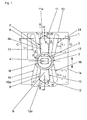
Fig. 1 eine Draufsicht auf einen Profilblock eines Laufstreifens eines Fahrzeugluftreifens mit eingesetztem Spike mit einer Ausführungsvariante der Erfindung, -
Fig. 1a einen Schnitt entlang der Linie 1a-1a derFig. 1 , -
Fig. 1b einen Schnitt entlang der Linie Ib-Ib derFig. 1 und -
Fig. 2 bis Fig. 5 Draufsichten auf Profilblöcke mit eingesetztem Spike mit weiteren Ausführungsvarianten der Erfindung. - Die
Figuren 1 bis 5 zeigen jeweils schematisch eine Draufsicht auf einen Profilblock 1 eines Laufstreifens eines Fahrzeugluftreifens, insbesondere eines Winterreifens in Radialbauart für Personenkraftwagen. Der Profilblock 1 kann beidseitig von einer sich in Umfangsrichtung des Laufstreifens, welche durch einen Doppelpfeil gekennzeichnet ist, verlaufenden Umfangsrille und durch je eine dem Profilblock 1 vor- und nachgeordneten, in axialer Richtung (Fig. 1 bis Fig. 4 ) oder unter einem spitzen Winkel zur axialen Richtung (Fig. 5 ) verlaufenden Querrille begrenzt sein. Die tatsächliche äußere Gestalt der Profilblöcke 1 kann von der vereinfacht dargestellten abweichen, sodass auch die vorgesehenen Rillen bezüglich der Umfangs- und Querrichtung beliebig orientiert sein können. Jeder Profilblock 1 kann ferner mit einer Anzahl nicht gezeigter, in an sich bekannter Weise ausgeführter Einschnitte versehen sein. Die Oberfläche 1a jedes Profilblockes 1 bildet die mit dem Untergrund beim Abrollen des Reifens in Kontakt kommende Fläche des Profilblockes 1. - Im Profilblock 1 ist in einem bei der Vulkanisation des Reifens erstellten Spikeloch ein insbesondere in an sich bekannter Weise ausgeführter Spike 2 mit einem Spikekörper 3 und einem Spikepin 4 eingesetzt und verankert. Der Spikekörper 3 weist bei der dargestellten Ausführungsform einen im Wesentlichen zylindrischen Basisteil mit einem Fußteil 5 und eine kreisrunde, ebene Oberfläche 6 auf. Das Spikeloch ist derart erstellt, dass die Oberfläche 6 entweder bündig mit der Oberfläche 1a des Profilblockes 1 abschließt oder sich geringfügig radial innerhalb der Oberfläche 1a befindet. Bei neuem Reifen beträgt der Abstand zwischen den Oberfläche 6 und der Oberfläche 1a nur wenige Zehntelmillimeter, insbesondere etwa 0,3 mm. Der im Spikekörper 3 verankerte Spikepin 4 erstreckt sich in radialer Richtung in den Spikekörper 3 hinein und überragt in bekannter Weise die Oberfläche 6 des Spikekörpers 3, sodass die Oberfläche 1a des Profilblockes 1 vom Spikepin 4 um 0,4 mm bis 2,0 mm, insbesondere um 1,0 mm, überragt wird. Bei den dargestellten Ausführungsvarianten ist der Spikepin 4 in Draufsicht länglich bzw. oval ausgeführt, wobei der Spike 2 vorzugsweise derart im Laufstreifen bzw. Profilblock 1 verankert wird, dass die größere Erstreckung des Spikepins 4 in axialer Richtung vorliegt.
- Die Erfindung wird anhand der
Figuren 1 ,1a und 1b nachfolgend im Detail erläutert. Im mittleren Bereich des beispielhaft als Rechteck dargestellten Profilblockes 1 ist der Spike 2 verankert. Unmittelbar beim eingesetzten Spike 2 beginnend sind im Profilblock 1 zentrisch zum Mittelpunkt M der Oberfläche 6 des Spikekörpers 3 oberflächlich zwei Ableitkanäle 7, 8 ausgebildet, wobei sich der eine Ableitkanal 7 in die eine Umfangsrichtung und der andere Ableitkanal 8 in die andere Umfangsrichtung erstreckt. - Jeder Ableitkanal 7, 8 ist bezüglich einer von der Umfangsrichtung und der radialen Richtung aufgespannten Symmetrieebene S symmetrisch gestaltet und weist einen Hauptabschnitt 9, 10 und einen Endabschnitt 11, 12 auf. Der Hauptabschnitt 9, 10 weist seitliche Begrenzungskanten 9a, 10a an der Oberfläche 1a des Profilblockes 1 auf, die sich unter einem spitzen Winkel α zur Umfangsrichtung, welcher 2° bis 10°, insbesondere 5°, beträgt, geradlinig erstrecken, wobei der gegenseitige Abstand b der Begrenzungskanten 9a, 10a mit zunehmender Entfernung vom Spike 2 größer wird. Der gegenseitige Abstand b der Begrenzungskanten 9a, 10a entspricht der Breite der Hauptabschnitte 9, 10 und beträgt an der Spikekante das 0,5- bis 1,5-Fache der axialen Breite b' des Spikepins 4. Im Hauptabschnitt 9, 10 des jeweiligen Ableitkanals 7, 8, nimmt die Tiefe des Ableitkanals 7, 8, beim Spike 2 beginnend, in Richtung zu den Endabschnitten 11, 12 der Ableitkanäle 7, 8 kontinuierlich zu. Wie
Fig. 1a und Fig. 1b zeigen, weist der Ableitkanal 7 im Hauptabschnitt 9 einen Boden 9b und seitliche Flanken 9c auf, die sich zwischen dem Boden 9b und den seitlichen Begrenzungskanten 9a in radialer Richtung erstrecken. Der Ableitkanal 8 ist auf analoge Weise ausgeführt, sein Boden 10b im Hauptabschnitt 10 ist inFig. 1a gezeigt. Die Hauptabschnitte 9, 10 der Ableitkanäle 7, 8 weisen beim Spike 2 eine Tiefe t1 von 0,5 mm bis 1,2 mm, insbesondere 0,8 mm bis 1,0 mm, auf. Am zweiten Ende der Hauptabschnitte 9, 10 beträgt ihre Tiefe t2 das 1,05- bis 3,6-Fache der Tiefe t1. Dabei kann die Ausführung ferner derart sein, dass die Hauptabschnitte 9, 10 im Querschnitt einen flach V-förmigen Boden 9b, 10b aufweisen, sodass die größte Tiefe t2 im Zentrum des Bodens 9b, 10b vorliegt, an den seitlichen Flanken 9c kann die Tiefe t2 geringfügig, um maximal 0,5 mm, insbesondere um maximal 0,3 mm, geringer sein. Bei lang ausgeführten Ableitkanälen 7, 8 beträgt t2 insbesondere das 1,6-Fache der Tiefe t1, bei kurz ausgeführten Ableitkanälen 7, 8 beträgt t2 insbesondere das 1,5-Fache der Tiefe t1. - Die jeweils in Umfangsrichtung entlang der Symmetrieebene S ermittelten maximalen Längen L7, L8 der Ableitkanäle 7, 8 sind an die jeweilige Position des Spikes 2 im Profilblock 1 und die Umfangsdimension des Profilblockes 1 angepasst und betragen 4 mm bis 14 mm. Der minimale Abstand a der Ableitkanäle 7, 8 von den in Querrichtung verlaufenden Profilblockkanten 1b beträgt 0,4 mm. Der Abstand a wird im rechten Winkel zur Erstreckung der betreffenden Profilblockkante 1b zwischen dieser und der dieser am nächsten liegenden Stelle des jeweiligen Ableitkanals 7, 8 ermittelt. Bei einer bevorzugten Ausführungsform der Erfindung beträgt der Abstand a bis zu 1 mm, kann jedoch, je nach Ausgestaltung des Profilblockes 1, in welchem der Spike 2 positioniert ist, auch wesentlich größer sein. Die Erstreckungslänge L9, L10 der Hauptabschnitte 9, 10 entlang der Symmetrieebene S beträgt je nach Ausführung und Anordnung der Spikes 2 in den Profilblöcken 1 und je nach der Ausführung der Profilblöcke 13 mm bis 12 mm.
- Die Endabschnitte 11, 12 der Ableitkanäle 7, 8 sind an der Oberfläche 1a des Profilblockes 1 jeweils von zwei Begrenzungskanten 11a, 12a begrenzt, die spitz zusammenlaufen und zueinander unter einem Winkel β von 95° bis 150°, insbesondere 110° bis 130°, vorzugsweise etwa 120°, verlaufen. Die Endabschnitte 11, 12 weisen jeweils einen Boden 11b, 12b sowie in den Figuren nicht zu sehende Flanken auf, die vom jeweiligen Boden 11b, 12b bis zu den Kanten 11a, 12a in radialer Richtung verlaufen. Innerhalb der Endabschnitte 11, 12 verringert sich die Tiefe kontinuierlich von der oben erwähnten Tiefe t2 auf eine Tiefe t3, die am Ende der Endabschnitte 11, 12 das 0,4- bis 2,4-Fache der Tiefe t1 beträgt, wobei vorzugsweise t3 = t1. Die Ableitkanäle 7, 8 können sich in ihren Erstreckungslängen unterscheiden, wobei es günstig ist, wenn der kürzere der beiden Ableitkanäle 7, 8 eine etwas grössere Tiefe aufweist als der längere.
- Optional verlaufen neben den Ableitkanälen 7, 8 Nebenkanäle 13, 14 und 15, 16. Bei den dargestellten Ausführungsformen verläuft auf jeder Seite des Ableitkanals 7 ein Nebenkanal 13, 14, auf jeder Seite des Ableitkanals 8 ein Nebenkanal 15, 16, jeweils im Wesentlichen parallel zur benachbarten seitlichen Begrenzungskante 9a, 10a des Hauptabschnittes 9, 10, in einem Abstand c von 1 mm bis 1,5 mm. Dabei kann der Abstand c über die Erstreckung der Nebenkanäle 13, 14, 15, 16 vom Spike 2 weg geringfügig, insbesondere um 0,1 mm bis 0,4 mm, größer werden. Zwischen den Nebenkanälen 13, 14, 15, 16 und dem Spike 2 bzw. dessen Spikekörper 3 befindet sich bei den dargestellten Ausführungen eine schmale, in Draufsicht vorzugsweise als Kreisringabschnitt ausgebildete Gummibrücke 17, deren Breite d 0,1 mm bis 0,2 mm beträgt. Die Nebenkanäle 13, 14, 15, 16 können jedoch auch unmittelbar bis zum Spikekörper 3 reichen. Die zweiten Enden der Nebenkanäle 13, 14, 15, 16 befinden sich ebenfalls innerhalb des Profilblockes 1, wobei der Abstand f dieser Enden der Nebenkanäle 13, 14, 15, 16 von der benachbarten Profilblockkante 1b mindestens 0,4 mm beträgt. Die Nebenkanäle 13, 14, 16, 16 weisen einen U-förmigen Querschnitt auf, ihre Breite e wird, abgesehen von ihrer Breite unmittelbar an ihren Endabschnitten, in ihrem Verlauf vom Spike 2 weg geringfügig größer und beträgt 1,5 mm bis 2,2 mm. Die Tiefe der Nebenkanäle 13, 14, 15, 16 ist über ihre Erstreckung im Wesentlichen konstant und beträgt 0,5 mm bis 0,7 mm, insbesondere 0,6 mm. Die in Umfangsrichtung vorliegenden Erstreckungslängen Ln der Nebenkanäle 13, 14, 15, 16 variieren je nach der Anordnung des Spikes 2 im Profilblock 1 und der Ausgestaltung bzw. äußeren Form des Profilblockes 1 zwischen 3 mm und 14 mm.
-
Fig. 1 zeigt eine Ausführungsform, bei der die Erstreckungslänge L7 des Ableitkanals 7 größer ist als die Erstreckungslänge L8 des Ableitkanals 8. Die beiden neben dem Ableitkanal 7 verlaufenden Nebenkanäle 13, 14 weisen übereinstimmende Erstreckungslängen Ln auf und überragen den Ableitkanal 7 in Umfangsrichtung, hier beispielhaft um etwa 0,5 mm. Die beiden neben dem Ableitkanal 8 verlaufenden Nebenkanäle 15, 16 erstrecken sich in Umfangsrichtung im Wesentlichen genauso weit wie der Ableitkanal 8. - Die in den
Figuren 2 bis 6 gezeigten Ausführungsformen sind Varianten der inFig. 1 gezeigten Ausführung der Erfindung. Es sind daher in diesen Figuren hauptsächlich die Ableitkanäle 7, 8, die Nebenkanäle 13, 14, 15, 16, der jeweils dargestellte Profilblock 1 und der Spike 2 mit Bezugsziffern versehen. -
Fig. 2 zeigt eine Ausführungsform, bei welcher der Spike 2 etwas außermittig im Profilblock 1 positioniert ist, sodass der Ableitkanal 7 eine größere Erstreckungslänge L7 aufweisen kann als der diesem gegenüber befindliche Ableitkanal 8. Bei dieser Ausführung weisen ferner die beiden neben dem Ableitkanal 7 verlaufenden Nebenkanäle 13, 14 eine etwas geringere Erstreckungslänge auf als der Ableitkanal 7, die beiden neben dem Ableitkanal 8 verlaufenden Nebenkanäle 15, 16 sind geringfügig länger ausgeführt als der Ableitkanal 8. -
Fig. 3 zeigt eine Ausführungsvariante, bei welcher der Spike 2 relativ weit zu der in dieser Figur unteren Profilblockkante 1b versetzt ist und demnach deutlich außermittig im Profilblock 1 positioniert ist. Bei dieser Ausführungsvariante weist der Ableitkanal 7 eine mehr als doppelt so große Erstreckungslänge L7 auf als der Ableitkanal 8. Die neben dem Ableitkanal 7 verlaufenden Nebenkanäle 13, 14 sind deutlich kürzer ausgeführt als der Ableitkanal 7, die neben dem Ableitkanal 8 angeordneten Nebenkanäle 15, 16 besitzen eine geringfügig größere Erstreckungslänge als der Ableitkanal 8. -
Fig. 4 zeigt eine Ausführungsform der Erfindung in einem Profilblock 1, dessen Umfangslänge größer ist als seine axiale Breite. Die Ableitkanäle 7, 8 weisen eine große Erstreckungslänge L7, L8 von beispielsweise 12 mm auf und sind hier gleich lang. Die Nebenkanäle 13, 14 und 15, 16 sind kürzer als die Ableitkanäle 7, 8 und in diesem Beispiel gleich lang. - Bei der in
Fig. 5 gezeigten Ausführungsform gehen vom etwa mittig im Profilblock 1 positionierten Spike 2 die beiden Ableitkanäle 7, 8 aus, die im Wesentlichen gleich große Erstreckungslängen L7, L8 aufweisen. Infolge der parallelogrammförmigen Ausführung des Profilblockes 1 mit stumpfen und spitzen Winkeln in den Blockecken können die beiden neben dem Ableitkanal 7 angeordneten Nebenkanäle 13, 14 unterschiedliche Erstreckungslängen aufweisen, der inFig. 5 links vom Ableitkanal 7 verlaufende Nebenkanal 13 ist kürzer ausgeführt als der inFig. 5 rechts vom Ableitkanal 7 verlaufende Nebenkanal 14, welcher infolge der Ausgestaltung des Profilblockes 1 Platz für eine größere Erstreckungslänge zur Verfügung hat. Dies trifft auch auf den links neben dem Ableitkanal 8 verlaufenden Nebenkanal 15 zu, der neben diesem Ableitkanal 8 rechts verlaufende Nebenkanal 16 ist wiederum kürzer ausgeführt. Wenn der Profilblock 1, wie dargestellt, gezackte Kanten 1b aufweist, kann die Erstreckungslänge der Nebenkanäle 14, 16 entsprechend angepasst werden. - Selbstverständlich sind weitere Ausführungsvarianten, die nicht dargestellt sind, möglich, insbesondere beliebige Kombinationen von Ableitkanälen 7, 8 mit Nebenkanälen unterschiedlicher Längen. Die Spikes können ferner auch deutlich ausserhalb des mittleren Bereiches eines Profilpositivs positioniert sein.
-
- 1....................... Profilblock
- 1a ..................... Oberfläche
- 1b ..................... Profilblockkante
- 2 ....................... Spike
- 3 ....................... Spikekörper
- 4 ....................... Spikepin
- 5 ....................... Fußteil
- 6 ....................... Oberfläche
- 7, 8 ................... Ableitkanal
- 9, 10 ................. Hauptabschnitt
- 9a, 10a ............. Begrenzungskante
- 9b,10b..............Boden
- 9c ..................... Flanke
- 11, 12............... Endabschnitt
- 11a, 12a ........... Begrenzungskante
- 11b, 12b ........... Boden
- 13, 14 ............... Nebenkanal
- 15, 16 ............... Nebenkanal
- 17 ..................... Gummibrücke
- a, b, c, f ............ Abstand
- b'...................... axiale Breite des Pins
- d, e ................... Breite
- L7, L8 ............... Erstreckungslänge
- L9, L10 .............. Erstreckungslänge
- Ln ..................... Erstreckungslänge
- l7, l8..................Längsachse
- M ..................... Mittelpunkt
- S ....................... Symmetrieebene
- t1, t2, t3.............. Tiefe
- α, β..................Winkel
Claims (15)
- Fahrzeugluftreifen mit einem Laufstreifen mit durch Rillen, wie Umfangsrillen, Schrägrillen, Querrillen, voneinander getrennten Profilpositiven (1), wie Profilblöcken, die jeweils eine mit dem Untergrund in Kontakt kommende Oberfläche (1a) aufweisen, wobei Profilpositive (1) vorgesehen sind, in welchen zumindest ein Spike (2) mit seinem Spikekörper (3) im Gummimaterial des Profilpositivs (1) verankert ist, wobei der Spike (2) einen Spikepin (4) aufweist, der in radialer Richtung aus dem Spikekörper (3) herausragt und die Oberfläche (1a) des Profilpositivs (1) überragt, wobei dem Spike (2) zumindest ein im Profilpositiv (1) als Vertiefung ausgebildeter Ableitkanal (7, 8) zur Aufnahme der beim Kratzen des Spikes auf Eis entstehenden Eissplitter zugeordnet ist,
dadurch gekennzeichnet,
dass an den in Umfangsrichtung gegenüber befindlichen Seiten des Spikekörpers (3) unmittelbar bei diesem beginnend je ein Ableitkanal (7, 8) vorgesehen ist, welcher innerhalb des jeweiligen Profilpositivs (1) endet, wobei jeder Ableitkanal (7, 8) einen über den Großteil seiner Längserstreckung verlaufenden Hauptabschnitt (9, 10), in welchem die Breite und die Tiefe (t1 t2) des Ableitkanals (7, 8) mit zunehmender Entfernung vom Spikekörper (3) zunehmen, und an diesen anschließend einen Endabschnitt (11, 12) aufweist, in welchem die Tiefe (t3) und die Breite des Ableitkanals (7, 8) mit zunehmender Entfernung vom Spikekörper (3) abnehmen. - Fahrzeugluftreifen nach Anspruch 1, dadurch gekennzeichnet, dass die Erstreckungslängen (L7, L8) der Ableitkanäle (7, 8) 4 mm bis 14 mm betragen.
- Fahrzeugluftreifen nach Anspruch 1 oder 2, dadurch gekennzeichnet, dass die Erstreckungslängen (L9, L10) der Hauptabschnitte (9, 10) 3 mm bis 12 mm betragen.
- Fahrzeugluftreifen nach einem der Ansprüche 1 bis 3, dadurch gekennzeichnet, dass die Hauptabschnitte (9, 10) beim Spikekörper (3) an der Spikekante eine Breite (b) aufweisen, die das 0,5- bis 1,5-Fache der axialen Breite (b') des Spikepins (4) entspricht.
- Fahrzeugluftreifen nach einem der Ansprüche 1 bis 4, dadurch gekennzeichnet, dass die Hauptabschnitte (9, 10) an der Oberfläche (1a) des Profilpositivs (1) von geradlinig verlaufenden Begrenzungskanten (9a, 10a) begrenzt sind, welche unter Vergrößerung ihres gegenseitigen Abstandes jeweils unter einem Winkel (α) von 2° bis 10° zur Umfangsrichtung verlaufen.
- Fahrzeugluftreifen nach einem der Ansprüche 1 bis 5, dadurch gekennzeichnet, dass die Tiefe (t1) der Hauptabschnitte (9, 10) beim Spikekörper (3) 0,5 mm bis 1,2 mm beträgt und in Richtung der Endabschnitte (11, 12) kontinuierlich auf eine Tiefe (t2) zunimmt, die das 1,05- bis 3,6-Fache der erstgenannten Tiefe (t1) entspricht.
- Fahrzeugluftreifen nach einem der Ansprüche 1 bis 6, dadurch gekennzeichnet, dass die Endabschnitte (11, 12) an der Oberfläche (1a) des Profilpositivs (1) von Begrenzungskanten (11a, 12a) begrenzt sind, die spitz zusammenlaufen und miteinander einen Winkel (β) von 95° bis 150°, insbesondere von 110° bis 130°, einschließen.
- Fahrzeugluftreifen nach einem der Ansprüche 1 bis 7, dadurch gekennzeichnet, dass die Tiefe der Endabschnitte (11, 12) am Schnittpunkt ihrer Begrenzungskanten (11a, 12a) geringer ist als die größte Tiefe der Hauptabschnitte (9, 10) und das 0,4- bis 2,4-Fache der Tiefe (t1) der Hauptabschnitte (9, 10) an der Spikekante beträgt.
- Fahrzeugluftreifen nach einem der Ansprüche 1 bis 8, dadurch gekennzeichnet, dass der Mindestabstand (a) der Ableitkanäle (7, 8) von benachbarten Profilpositivkanten (1b) 0,5 mm beträgt.
- Fahrzeugluftreifen nach einem der Ansprüche 1 bis 9, dadurch gekennzeichnet, dass neben den Ableitkanälen (7, 8) innerhalb des Profilpositivs (1) im Wesentlichen parallel zu den Ableitkanälen (7, 8) Nebenkanäle (13, 14, 15, 16) verlaufen.
- Fahrzeugluftreifen nach einem der Ansprüche 1 bis 10, dadurch gekennzeichnet, dass der Abstand (c) zwischen den Ableitkanälen (7, 8) und den Nebenkanälen (13, 14, 15, 16) 1 mm bis 1,5 mm beträgt.
- Fahrzeugluftreifen nach einem der Ansprüche 1 bis 11, dadurch gekennzeichnet, dass die Nebenkanäle (13, 14, 15, 16) über den Großteil ihrer Erstreckung eine Breite (e) von 1,5 mm bis 2,2 mm aufweisen, wobei vorzugsweise diese Breite (e) über die Erstreckung der Nebenkanäle (13, 14, 15, 16) in Richtung vom Spike (2) weg kontinuierlich geringer wird.
- Fahrzeugluftreifen nach einem der Ansprüche 1 bis 12, dadurch gekennzeichnet, dass die Nebenkanäle (13, 14, 15, 16) eine insbesondere konstante Tiefe von 0,5 mm bis 0,7 mm aufweisen.
- Fahrzeugluftreifen nach einem der Ansprüche 1 bis 13, dadurch gekennzeichnet, dass der Mindestabstand (f) der Nebenkanäle (13, 14, 15, 16) von benachbarten Profilpositivkanten (1b) 0,4 mm beträgt.
- Fahrzeugluftreifen nach einem der Ansprüche 1 bis 14, dadurch gekennzeichnet, dass die Nebenkanäle (13, 14, 15, 16) Erstreckungslängen (Ln) aufweisen, die 3 mm bis 14 mm betragen.
Applications Claiming Priority (1)
| Application Number | Priority Date | Filing Date | Title |
|---|---|---|---|
| DE102014225047.1A DE102014225047A1 (de) | 2014-12-05 | 2014-12-05 | Fahrzeugluftreifen |
Publications (2)
| Publication Number | Publication Date |
|---|---|
| EP3031628A1 true EP3031628A1 (de) | 2016-06-15 |
| EP3031628B1 EP3031628B1 (de) | 2017-05-31 |
Family
ID=54196865
Family Applications (1)
| Application Number | Title | Priority Date | Filing Date |
|---|---|---|---|
| EP15186362.8A Active EP3031628B1 (de) | 2014-12-05 | 2015-09-23 | Fahrzeugluftreifen |
Country Status (2)
| Country | Link |
|---|---|
| EP (1) | EP3031628B1 (de) |
| DE (1) | DE102014225047A1 (de) |
Cited By (5)
| Publication number | Priority date | Publication date | Assignee | Title |
|---|---|---|---|---|
| WO2017071842A1 (de) * | 2015-10-29 | 2017-05-04 | Continental Reifen Deutschland Gmbh | Fahrzeugluftreifen |
| WO2020012281A1 (en) * | 2018-07-13 | 2020-01-16 | Pirelli Tyre S.P.A. | Studded tyre for vehicle wheels |
| WO2020156741A1 (de) * | 2019-02-01 | 2020-08-06 | Continental Reifen Deutschland Gmbh | Fahrzeugluftreifen |
| CN111572287A (zh) * | 2019-02-19 | 2020-08-25 | 住友橡胶工业株式会社 | 轮胎 |
| RU2800025C2 (ru) * | 2019-02-19 | 2023-07-14 | Сумитомо Раббер Индастриз, Лтд. | Шина |
Families Citing this family (2)
| Publication number | Priority date | Publication date | Assignee | Title |
|---|---|---|---|---|
| DE102017207316A1 (de) | 2017-05-02 | 2018-11-08 | Continental Reifen Deutschland Gmbh | Fahrzeugluftreifen |
| DE102023205212A1 (de) | 2023-06-05 | 2024-12-05 | Continental Reifen Deutschland Gmbh | Kombination aus einem Fahrzeugluftreifen und Spikes und Fahrzeugluftreifen |
Citations (4)
| Publication number | Priority date | Publication date | Assignee | Title |
|---|---|---|---|---|
| EP2285600B1 (de) | 2008-06-03 | 2012-01-04 | Société de Technologie MICHELIN | Reifen zum fahren auf eis |
| EP2285599B1 (de) | 2008-06-03 | 2012-09-05 | Compagnie Generale Des Etablissements Michelin | Reifen zum fahren auf eis |
| EP2501562B1 (de) | 2009-11-16 | 2013-07-24 | Continental Reifen Deutschland GmbH | Laufstreifenprofil eines fahrzeugluftreifens |
| WO2014123181A1 (ja) * | 2013-02-07 | 2014-08-14 | 株式会社ブリヂストン | スタッダブルタイヤ |
-
2014
- 2014-12-05 DE DE102014225047.1A patent/DE102014225047A1/de not_active Withdrawn
-
2015
- 2015-09-23 EP EP15186362.8A patent/EP3031628B1/de active Active
Patent Citations (4)
| Publication number | Priority date | Publication date | Assignee | Title |
|---|---|---|---|---|
| EP2285600B1 (de) | 2008-06-03 | 2012-01-04 | Société de Technologie MICHELIN | Reifen zum fahren auf eis |
| EP2285599B1 (de) | 2008-06-03 | 2012-09-05 | Compagnie Generale Des Etablissements Michelin | Reifen zum fahren auf eis |
| EP2501562B1 (de) | 2009-11-16 | 2013-07-24 | Continental Reifen Deutschland GmbH | Laufstreifenprofil eines fahrzeugluftreifens |
| WO2014123181A1 (ja) * | 2013-02-07 | 2014-08-14 | 株式会社ブリヂストン | スタッダブルタイヤ |
Cited By (8)
| Publication number | Priority date | Publication date | Assignee | Title |
|---|---|---|---|---|
| WO2017071842A1 (de) * | 2015-10-29 | 2017-05-04 | Continental Reifen Deutschland Gmbh | Fahrzeugluftreifen |
| WO2020012281A1 (en) * | 2018-07-13 | 2020-01-16 | Pirelli Tyre S.P.A. | Studded tyre for vehicle wheels |
| EP4070971A1 (de) * | 2018-07-13 | 2022-10-12 | Pirelli Tyre S.p.A. | Spikereifen für fahrzeugräder |
| EP4074523A1 (de) * | 2018-07-13 | 2022-10-19 | Pirelli Tyre S.p.A. | Spikereifen für fahrzeugräder |
| WO2020156741A1 (de) * | 2019-02-01 | 2020-08-06 | Continental Reifen Deutschland Gmbh | Fahrzeugluftreifen |
| CN111572287A (zh) * | 2019-02-19 | 2020-08-25 | 住友橡胶工业株式会社 | 轮胎 |
| EP3698985A1 (de) * | 2019-02-19 | 2020-08-26 | Sumitomo Rubber Industries, Ltd. | Reifen |
| RU2800025C2 (ru) * | 2019-02-19 | 2023-07-14 | Сумитомо Раббер Индастриз, Лтд. | Шина |
Also Published As
| Publication number | Publication date |
|---|---|
| EP3031628B1 (de) | 2017-05-31 |
| DE102014225047A1 (de) | 2016-06-09 |
Similar Documents
| Publication | Publication Date | Title |
|---|---|---|
| EP3031628B1 (de) | Fahrzeugluftreifen | |
| EP2892736B1 (de) | Fahrzeugluftreifen | |
| EP3256333B1 (de) | Fahrzeugluftreifen | |
| EP3256334B1 (de) | Fahrzeugluftreifen | |
| EP3181378B1 (de) | Fahrzeugluftreifen | |
| EP3390110B1 (de) | Fahrzeugluftreifen | |
| DE102010060946A1 (de) | Fahrzeugluftreifen | |
| EP3300926B1 (de) | Fahrzeugluftreifen | |
| EP3368345B1 (de) | Fahrzeugluftreifen | |
| EP3421264B1 (de) | Fahrzeugluftreifen | |
| EP3009275B1 (de) | Fahrzeugluftreifen | |
| WO2019001790A1 (de) | Fahrzeugluftreifen | |
| EP3475103B1 (de) | Fahrzeugluftreifen | |
| EP3724008B1 (de) | Spike und fahrzeugluftreifen mit im laufstreifen verankerten spikes | |
| EP3277523B1 (de) | Fahrzeugluftreifen | |
| EP3383675B1 (de) | Fahrzeugluftreifen | |
| EP3619057B1 (de) | Fahrzeugluftreifen | |
| EP3256335B1 (de) | Fahrzeugluftreifen | |
| EP3538382B1 (de) | Fahrzeugluftreifen | |
| EP3390108B1 (de) | Fahrzeugluftreifen | |
| EP3750723B1 (de) | Fahrzeugluftreifen | |
| DE102008055496A1 (de) | Fahrzeugluftreifen | |
| EP3450213A1 (de) | Fahrzeugluftreifen | |
| EP3230086B1 (de) | Fahrzeugluftreifen | |
| EP2138328B1 (de) | Fahrzeugluftreifen |
Legal Events
| Date | Code | Title | Description |
|---|---|---|---|
| PUAI | Public reference made under article 153(3) epc to a published international application that has entered the european phase |
Free format text: ORIGINAL CODE: 0009012 |
|
| AK | Designated contracting states |
Kind code of ref document: A1 Designated state(s): AL AT BE BG CH CY CZ DE DK EE ES FI FR GB GR HR HU IE IS IT LI LT LU LV MC MK MT NL NO PL PT RO RS SE SI SK SM TR |
|
| AX | Request for extension of the european patent |
Extension state: BA ME |
|
| 17P | Request for examination filed |
Effective date: 20161215 |
|
| RBV | Designated contracting states (corrected) |
Designated state(s): AL AT BE BG CH CY CZ DE DK EE ES FI FR GB GR HR HU IE IS IT LI LT LU LV MC MK MT NL NO PL PT RO RS SE SI SK SM TR |
|
| REG | Reference to a national code |
Ref country code: DE Ref legal event code: R079 Ref document number: 502015001143 Country of ref document: DE Free format text: PREVIOUS MAIN CLASS: B60C0011160000 Ipc: B60C0011030000 |
|
| GRAP | Despatch of communication of intention to grant a patent |
Free format text: ORIGINAL CODE: EPIDOSNIGR1 |
|
| RIC1 | Information provided on ipc code assigned before grant |
Ipc: B60C 11/16 20060101ALI20170206BHEP Ipc: B60C 11/03 20060101AFI20170206BHEP Ipc: B60C 11/11 20060101ALI20170206BHEP |
|
| INTG | Intention to grant announced |
Effective date: 20170221 |
|
| GRAS | Grant fee paid |
Free format text: ORIGINAL CODE: EPIDOSNIGR3 |
|
| GRAA | (expected) grant |
Free format text: ORIGINAL CODE: 0009210 |
|
| AK | Designated contracting states |
Kind code of ref document: B1 Designated state(s): AL AT BE BG CH CY CZ DE DK EE ES FI FR GB GR HR HU IE IS IT LI LT LU LV MC MK MT NL NO PL PT RO RS SE SI SK SM TR |
|
| REG | Reference to a national code |
Ref country code: CH Ref legal event code: EP Ref country code: GB Ref legal event code: FG4D Free format text: NOT ENGLISH |
|
| REG | Reference to a national code |
Ref country code: AT Ref legal event code: REF Ref document number: 897077 Country of ref document: AT Kind code of ref document: T Effective date: 20170615 |
|
| REG | Reference to a national code |
Ref country code: IE Ref legal event code: FG4D Free format text: LANGUAGE OF EP DOCUMENT: GERMAN |
|
| REG | Reference to a national code |
Ref country code: DE Ref legal event code: R096 Ref document number: 502015001143 Country of ref document: DE |
|
| REG | Reference to a national code |
Ref country code: SE Ref legal event code: TRGR |
|
| REG | Reference to a national code |
Ref country code: NL Ref legal event code: MP Effective date: 20170531 |
|
| REG | Reference to a national code |
Ref country code: LT Ref legal event code: MG4D |
|
| REG | Reference to a national code |
Ref country code: NO Ref legal event code: T2 Effective date: 20170531 |
|
| PG25 | Lapsed in a contracting state [announced via postgrant information from national office to epo] |
Ref country code: LT Free format text: LAPSE BECAUSE OF FAILURE TO SUBMIT A TRANSLATION OF THE DESCRIPTION OR TO PAY THE FEE WITHIN THE PRESCRIBED TIME-LIMIT Effective date: 20170531 Ref country code: ES Free format text: LAPSE BECAUSE OF FAILURE TO SUBMIT A TRANSLATION OF THE DESCRIPTION OR TO PAY THE FEE WITHIN THE PRESCRIBED TIME-LIMIT Effective date: 20170531 Ref country code: HR Free format text: LAPSE BECAUSE OF FAILURE TO SUBMIT A TRANSLATION OF THE DESCRIPTION OR TO PAY THE FEE WITHIN THE PRESCRIBED TIME-LIMIT Effective date: 20170531 Ref country code: GR Free format text: LAPSE BECAUSE OF FAILURE TO SUBMIT A TRANSLATION OF THE DESCRIPTION OR TO PAY THE FEE WITHIN THE PRESCRIBED TIME-LIMIT Effective date: 20170901 |
|
| PG25 | Lapsed in a contracting state [announced via postgrant information from national office to epo] |
Ref country code: IS Free format text: LAPSE BECAUSE OF FAILURE TO SUBMIT A TRANSLATION OF THE DESCRIPTION OR TO PAY THE FEE WITHIN THE PRESCRIBED TIME-LIMIT Effective date: 20170930 Ref country code: RS Free format text: LAPSE BECAUSE OF FAILURE TO SUBMIT A TRANSLATION OF THE DESCRIPTION OR TO PAY THE FEE WITHIN THE PRESCRIBED TIME-LIMIT Effective date: 20170531 Ref country code: NL Free format text: LAPSE BECAUSE OF FAILURE TO SUBMIT A TRANSLATION OF THE DESCRIPTION OR TO PAY THE FEE WITHIN THE PRESCRIBED TIME-LIMIT Effective date: 20170531 Ref country code: BG Free format text: LAPSE BECAUSE OF FAILURE TO SUBMIT A TRANSLATION OF THE DESCRIPTION OR TO PAY THE FEE WITHIN THE PRESCRIBED TIME-LIMIT Effective date: 20170831 Ref country code: LV Free format text: LAPSE BECAUSE OF FAILURE TO SUBMIT A TRANSLATION OF THE DESCRIPTION OR TO PAY THE FEE WITHIN THE PRESCRIBED TIME-LIMIT Effective date: 20170531 |
|
| PG25 | Lapsed in a contracting state [announced via postgrant information from national office to epo] |
Ref country code: DK Free format text: LAPSE BECAUSE OF FAILURE TO SUBMIT A TRANSLATION OF THE DESCRIPTION OR TO PAY THE FEE WITHIN THE PRESCRIBED TIME-LIMIT Effective date: 20170531 Ref country code: EE Free format text: LAPSE BECAUSE OF FAILURE TO SUBMIT A TRANSLATION OF THE DESCRIPTION OR TO PAY THE FEE WITHIN THE PRESCRIBED TIME-LIMIT Effective date: 20170531 Ref country code: CZ Free format text: LAPSE BECAUSE OF FAILURE TO SUBMIT A TRANSLATION OF THE DESCRIPTION OR TO PAY THE FEE WITHIN THE PRESCRIBED TIME-LIMIT Effective date: 20170531 Ref country code: RO Free format text: LAPSE BECAUSE OF FAILURE TO SUBMIT A TRANSLATION OF THE DESCRIPTION OR TO PAY THE FEE WITHIN THE PRESCRIBED TIME-LIMIT Effective date: 20170531 Ref country code: SK Free format text: LAPSE BECAUSE OF FAILURE TO SUBMIT A TRANSLATION OF THE DESCRIPTION OR TO PAY THE FEE WITHIN THE PRESCRIBED TIME-LIMIT Effective date: 20170531 |
|
| PG25 | Lapsed in a contracting state [announced via postgrant information from national office to epo] |
Ref country code: IT Free format text: LAPSE BECAUSE OF FAILURE TO SUBMIT A TRANSLATION OF THE DESCRIPTION OR TO PAY THE FEE WITHIN THE PRESCRIBED TIME-LIMIT Effective date: 20170531 Ref country code: PL Free format text: LAPSE BECAUSE OF FAILURE TO SUBMIT A TRANSLATION OF THE DESCRIPTION OR TO PAY THE FEE WITHIN THE PRESCRIBED TIME-LIMIT Effective date: 20170531 Ref country code: SM Free format text: LAPSE BECAUSE OF FAILURE TO SUBMIT A TRANSLATION OF THE DESCRIPTION OR TO PAY THE FEE WITHIN THE PRESCRIBED TIME-LIMIT Effective date: 20170531 |
|
| REG | Reference to a national code |
Ref country code: DE Ref legal event code: R097 Ref document number: 502015001143 Country of ref document: DE |
|
| PLBE | No opposition filed within time limit |
Free format text: ORIGINAL CODE: 0009261 |
|
| STAA | Information on the status of an ep patent application or granted ep patent |
Free format text: STATUS: NO OPPOSITION FILED WITHIN TIME LIMIT |
|
| 26N | No opposition filed |
Effective date: 20180301 |
|
| PG25 | Lapsed in a contracting state [announced via postgrant information from national office to epo] |
Ref country code: MC Free format text: LAPSE BECAUSE OF FAILURE TO SUBMIT A TRANSLATION OF THE DESCRIPTION OR TO PAY THE FEE WITHIN THE PRESCRIBED TIME-LIMIT Effective date: 20170531 Ref country code: SI Free format text: LAPSE BECAUSE OF FAILURE TO SUBMIT A TRANSLATION OF THE DESCRIPTION OR TO PAY THE FEE WITHIN THE PRESCRIBED TIME-LIMIT Effective date: 20170531 |
|
| REG | Reference to a national code |
Ref country code: IE Ref legal event code: MM4A |
|
| REG | Reference to a national code |
Ref country code: BE Ref legal event code: MM Effective date: 20170930 |
|
| PG25 | Lapsed in a contracting state [announced via postgrant information from national office to epo] |
Ref country code: LU Free format text: LAPSE BECAUSE OF NON-PAYMENT OF DUE FEES Effective date: 20170923 |
|
| REG | Reference to a national code |
Ref country code: FR Ref legal event code: ST Effective date: 20180531 |
|
| PG25 | Lapsed in a contracting state [announced via postgrant information from national office to epo] |
Ref country code: IE Free format text: LAPSE BECAUSE OF NON-PAYMENT OF DUE FEES Effective date: 20170923 |
|
| PG25 | Lapsed in a contracting state [announced via postgrant information from national office to epo] |
Ref country code: FR Free format text: LAPSE BECAUSE OF NON-PAYMENT OF DUE FEES Effective date: 20171002 Ref country code: BE Free format text: LAPSE BECAUSE OF NON-PAYMENT OF DUE FEES Effective date: 20170930 |
|
| PG25 | Lapsed in a contracting state [announced via postgrant information from national office to epo] |
Ref country code: MT Free format text: LAPSE BECAUSE OF FAILURE TO SUBMIT A TRANSLATION OF THE DESCRIPTION OR TO PAY THE FEE WITHIN THE PRESCRIBED TIME-LIMIT Effective date: 20170531 |
|
| PGFP | Annual fee paid to national office [announced via postgrant information from national office to epo] |
Ref country code: NO Payment date: 20180925 Year of fee payment: 4 |
|
| REG | Reference to a national code |
Ref country code: CH Ref legal event code: PL |
|
| PG25 | Lapsed in a contracting state [announced via postgrant information from national office to epo] |
Ref country code: HU Free format text: LAPSE BECAUSE OF FAILURE TO SUBMIT A TRANSLATION OF THE DESCRIPTION OR TO PAY THE FEE WITHIN THE PRESCRIBED TIME-LIMIT; INVALID AB INITIO Effective date: 20150923 |
|
| PG25 | Lapsed in a contracting state [announced via postgrant information from national office to epo] |
Ref country code: CH Free format text: LAPSE BECAUSE OF NON-PAYMENT OF DUE FEES Effective date: 20180930 Ref country code: LI Free format text: LAPSE BECAUSE OF NON-PAYMENT OF DUE FEES Effective date: 20180930 |
|
| PG25 | Lapsed in a contracting state [announced via postgrant information from national office to epo] |
Ref country code: CY Free format text: LAPSE BECAUSE OF FAILURE TO SUBMIT A TRANSLATION OF THE DESCRIPTION OR TO PAY THE FEE WITHIN THE PRESCRIBED TIME-LIMIT Effective date: 20170531 |
|
| PG25 | Lapsed in a contracting state [announced via postgrant information from national office to epo] |
Ref country code: MK Free format text: LAPSE BECAUSE OF FAILURE TO SUBMIT A TRANSLATION OF THE DESCRIPTION OR TO PAY THE FEE WITHIN THE PRESCRIBED TIME-LIMIT Effective date: 20170531 |
|
| PG25 | Lapsed in a contracting state [announced via postgrant information from national office to epo] |
Ref country code: TR Free format text: LAPSE BECAUSE OF FAILURE TO SUBMIT A TRANSLATION OF THE DESCRIPTION OR TO PAY THE FEE WITHIN THE PRESCRIBED TIME-LIMIT Effective date: 20170531 |
|
| REG | Reference to a national code |
Ref country code: NO Ref legal event code: MMEP |
|
| PG25 | Lapsed in a contracting state [announced via postgrant information from national office to epo] |
Ref country code: PT Free format text: LAPSE BECAUSE OF FAILURE TO SUBMIT A TRANSLATION OF THE DESCRIPTION OR TO PAY THE FEE WITHIN THE PRESCRIBED TIME-LIMIT Effective date: 20170531 |
|
| PG25 | Lapsed in a contracting state [announced via postgrant information from national office to epo] |
Ref country code: NO Free format text: LAPSE BECAUSE OF NON-PAYMENT OF DUE FEES Effective date: 20190930 Ref country code: AL Free format text: LAPSE BECAUSE OF FAILURE TO SUBMIT A TRANSLATION OF THE DESCRIPTION OR TO PAY THE FEE WITHIN THE PRESCRIBED TIME-LIMIT Effective date: 20170531 |
|
| GBPC | Gb: european patent ceased through non-payment of renewal fee |
Effective date: 20190923 |
|
| PG25 | Lapsed in a contracting state [announced via postgrant information from national office to epo] |
Ref country code: GB Free format text: LAPSE BECAUSE OF NON-PAYMENT OF DUE FEES Effective date: 20190923 |
|
| REG | Reference to a national code |
Ref country code: AT Ref legal event code: MM01 Ref document number: 897077 Country of ref document: AT Kind code of ref document: T Effective date: 20200923 |
|
| PG25 | Lapsed in a contracting state [announced via postgrant information from national office to epo] |
Ref country code: AT Free format text: LAPSE BECAUSE OF NON-PAYMENT OF DUE FEES Effective date: 20200923 |
|
| REG | Reference to a national code |
Ref country code: DE Ref legal event code: R081 Ref document number: 502015001143 Country of ref document: DE Owner name: CONTINENTAL REIFEN DEUTSCHLAND GMBH, DE Free format text: FORMER OWNER: CONTINENTAL REIFEN DEUTSCHLAND GMBH, 30165 HANNOVER, DE |
|
| PGFP | Annual fee paid to national office [announced via postgrant information from national office to epo] |
Ref country code: FI Payment date: 20240918 Year of fee payment: 10 |
|
| PGFP | Annual fee paid to national office [announced via postgrant information from national office to epo] |
Ref country code: SE Payment date: 20240919 Year of fee payment: 10 |
|
| PGFP | Annual fee paid to national office [announced via postgrant information from national office to epo] |
Ref country code: DE Payment date: 20250930 Year of fee payment: 11 |
|
| PG25 | Lapsed in a contracting state [announced via postgrant information from national office to epo] |
Ref country code: FI Free format text: LAPSE BECAUSE OF NON-PAYMENT OF DUE FEES Effective date: 20250923 |