EP3030511B1 - Roundslings with radio frequency identification pre-failure warning indicators - Google Patents
Roundslings with radio frequency identification pre-failure warning indicators Download PDFInfo
- Publication number
- EP3030511B1 EP3030511B1 EP14704940.7A EP14704940A EP3030511B1 EP 3030511 B1 EP3030511 B1 EP 3030511B1 EP 14704940 A EP14704940 A EP 14704940A EP 3030511 B1 EP3030511 B1 EP 3030511B1
- Authority
- EP
- European Patent Office
- Prior art keywords
- rfid
- roundsling
- core
- failure
- warning system
- Prior art date
- Legal status (The legal status is an assumption and is not a legal conclusion. Google has not performed a legal analysis and makes no representation as to the accuracy of the status listed.)
- Active
Links
Images







Classifications
-
- B—PERFORMING OPERATIONS; TRANSPORTING
- B66—HOISTING; LIFTING; HAULING
- B66C—CRANES; LOAD-ENGAGING ELEMENTS OR DEVICES FOR CRANES, CAPSTANS, WINCHES, OR TACKLES
- B66C1/00—Load-engaging elements or devices attached to lifting or lowering gear of cranes or adapted for connection therewith for transmitting lifting forces to articles or groups of articles
- B66C1/10—Load-engaging elements or devices attached to lifting or lowering gear of cranes or adapted for connection therewith for transmitting lifting forces to articles or groups of articles by mechanical means
- B66C1/12—Slings comprising chains, wires, ropes, or bands; Nets
-
- B—PERFORMING OPERATIONS; TRANSPORTING
- B66—HOISTING; LIFTING; HAULING
- B66C—CRANES; LOAD-ENGAGING ELEMENTS OR DEVICES FOR CRANES, CAPSTANS, WINCHES, OR TACKLES
- B66C15/00—Safety gear
-
- D—TEXTILES; PAPER
- D07—ROPES; CABLES OTHER THAN ELECTRIC
- D07B—ROPES OR CABLES IN GENERAL
- D07B1/00—Constructional features of ropes or cables
- D07B1/14—Ropes or cables with incorporated auxiliary elements, e.g. for marking, extending throughout the length of the rope or cable
- D07B1/145—Ropes or cables with incorporated auxiliary elements, e.g. for marking, extending throughout the length of the rope or cable comprising elements for indicating or detecting the rope or cable status
Definitions
- the invention relates generally to industrial slings used to lift, move and transport heavy loads and, more particularly, relates to RFID-based warning indicators that notify an operator of the sling of a condition that if not mitigated may lead to failure of the sling.
- Industrial slings are typically prepared from metals or synthetic materials.
- Wire rope slings are commonly made of a plurality of metal strands twisted together and secured by large metal sleeves or collars.
- Synthetic slings are usually comprised of a lifting core made of twisted strands of synthetic fiber and an outer cover that protects the core.
- One popular design of synthetic slings is a roundsling in which the lifting core forms a continuous loop and the sling has a circular or oval-shaped appearance.
- Modern industrial slings may experience failure and loss of a load caused by the sling breaking or failing, for example, because it was fatigued or because it was over-stretched or over-loaded during a current or previous use.
- a roundsling When subjected to an overload condition in excess of its rated capacity, a roundsling may be permanently damaged/deformed if the load stretches the fibers of the load bearing core material beyond their yield point.
- a synthetic fiber sling is overloaded beyond its tensile strength or weight-lifting capacity at maximum stretch, it is considered to be fatigued and may never return to its normal strength and load bearing capacity.
- Slings are generally provided with their load capacity (rated capacity) specified, particular sling. This allows users to know the lifting or load capacity of the sling. Nevertheless, this capacity is sometimes exceeded, either accidentally or by users engaging unsafe shortcuts during rigging and use of the sling. Often, over-load, fatigue, or damage to the sling materials may not be readily apparent, particularly given the large size or length of the sling, or because the load-bearing core is hidden inside the outer cover. If a roundsling has been fatigued or structurally changed, the sling may no longer be able to lift a load according to its maximum rated load capacity. Such a condition may potentially become a serious threat to the operators and riggers using the damaged sling.
- load capacity rated capacity
- the systems comprise a roundsling comprising a load-bearing core, an indicator yarn comprising at least one radio frequency identification (RFID) tag affixed to the indicator yarn, and one or more RFID sensors comprising a transmitter for sending a wireless signal to a RFID signal receiver, and also comprise a RFID signal receiver.
- RFID radio frequency identification
- the systems may further comprise a pre-failure indicator assembly comprising a dedicated strand having an eye-loop on each end joined together via one or more rings that fail at a load capacity that is less than the maximum load capacity of the load-bearing core.
- the dedicated strand is preferably positioned proximate to the core.
- the indicator yarn is preferably connected to the dedicated strand.
- the indicator yarn is preferably brightly colored in order to be readily visible to operators or the roundsling.
- the RFID signal receiver may comprise hand-held wireless device such as a cellular telephone, tablet computer, or other form of wireless computer, and informs a user of a pre-failure condition with the roundsling by one or more of emitting an audible alarm, displaying a visible warning, and/or producing a tactile alarm.
- the roundsling may be a one-path or two-path roundsling.
- each path comprises a load-bearing core, an indicator yarn comprising one or more RFID tags affixed to the indicator yarn, and one or more RFID sensors comprising a transmitter for sending a wireless signal to a RFID signal receiver.
- Each path may further comprise a pre-failure indicator assembly comprising a dedicated strand having an eye-loop on each end joined together via one or more rings that fail at a load capacity that is less than the maximum load capacity of the load-bearing core.
- the dedicated strand is preferably positioned proximate to the core.
- the indicator yarn is preferably connected to the dedicated strand.
- the indicator yarn is preferably brightly colored in order to be readily visible to operators or the roundsling.
- the systems comprise a roundsling comprising a load-bearing core, a pre-failure indicator assembly comprising a dedicated strand positioned proximate to the core and having an eye-loop on each end joined together via one or more rings that fail at a load capacity that is less than the maximum load capacity of the load-bearing core, and having one or more RFID tags affixed to the dedicated strand, and one or more RFID sensors comprising a transmitter for sending a wireless signal to a RFID signal receiver, and a RFID signal receiver.
- the RFID signal receiver may comprise hand-held wireless device such as a cellular telephone, tablet computer, or other form of wireless computer, and informs a user of a pre-failure condition with the roundsling by one or more of emitting an audible alarm, displaying a visible warning, and/or producing a tactile alarm.
- hand-held wireless device such as a cellular telephone, tablet computer, or other form of wireless computer
- the systems comprise a roundsling comprising a load-bearing core, a pre-failure indicator assembly comprising a dedicated strand having an eye-loop on each end joined together via one or more rings that fail at a load capacity that is less than the maximum load capacity of the load-bearing core.
- the ring preferably comprises one or more active RFID tags.
- the one or more RFID tags may optionally comprise a shield that blocks the signal transmitted from the RFID tag. If the shield is compromised, the signal may escape through the compromised area and the freed signal may be detected.
- the systems may comprise an indicator yarn connected to the dedicated strand.
- the systems also comprise a RFID signal receiver.
- the dedicated strand may comprise a plurality of RFID tags, or may comprise at least two, at least three, or at least four, or more than four RFID tags.
- the roundsling may comprise two or more RFID sensors.
- An indicator yarn may be attached to the dedicated strand, with an end portion of the indicator yarn exposed to the exterior of the cover.
- the roundsling may be a one-path or two-path roundsling.
- each path comprises a load-bearing core, a pre-failure indicator assembly comprising a dedicated strand positioned proximate to the core and having an eye-loop on each end joined together via one or more rings that fail at a load capacity that is less than the maximum load capacity of the load-bearing core, and having one or more RFID tags affixed to the dedicated strand, and one or more RFID sensors comprising a transmitter for sending a wireless signal to a RFID signal receiver.
- the disclosure relates to systems and methods for determining whether an industrial roundsling may fail during use, for example, because load-bearing aspects of the roundsling have been overstretched or overloaded.
- a foundational feature includes radio frequency identification tags and sensors that convey information about the condition of the load-bearing aspects of the roundsling to a user.
- the roundslings may comprise the roundslings and the sacrificial ring-based pre-failure indicator systems of U.S. Pat. No. 7,661,737 .
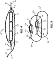
- FIG. 1A illustrates one non-limiting example of a single-path roundsling 10.
- the single-path roundsling 10 comprises a load-bearing core 12.
- the core 12 may be comprised of a plurality of strands 13 ( FIG. 2 ), that may be fabricated from any suitable material, including metal or synthetic polymers or composite materials.
- the core 12 may comprise one or more natural or synthetic materials, such as polyester, polyethylene, nylon, K-Spec ® (SlingMax, Inc., comprising a proprietary blend of fibers), high-modulus polyethylene (HMPE), liquid crystal polymer (LCP), aramid, para-aramid, or other suitable synthetic material.
- HMPE high-modulus polyethylene
- LCP liquid crystal polymer
- aramid para-aramid
- the material of the core 12 may relate to the maximum weight the sling 10 is designed to lift, and the environment in which the sling 10 will be used.
- synthetic strands 13 have a high lifting and break strength, lighter weight, high temperature resistance and high durability, compared to wire rope or metal chain slings.
- the core 12 is housed within a protective cover 14.
- the core 12 generally bears substantially the entire weight of the load to be lifted.
- the cover 14 generally prevents physical damage to the core 12, for example from abrasion, and sharp edges on the load, as well as protects the core 12 from exposure to harsh environmental conditions such as heat, humidity, ultraviolet light, corrosive chemicals, gaseous materials, or other environmental conditions that may damage or weaken the core 12 materials.
- the single-path roundsling 10 may also comprise an indicator yarn 18, as well as a label 16.
- the cover 14 may comprise an opening through which the indicator yarn 18 may pass through, with a length of the yarn 18 and one terminal end thus located inside of the cover 14, and a length of the yarn 18 and the other terminal end thus located outside of the cover 14.
- the opening may be located underneath the label 16, but may be located at any suitable position in the cover 14.
- the yarn 18 may extend out from the label 16, with a length of one end portion extending freely beyond the surface of the cover 14.
- the yarn 18 preferably is of a bright color, including yellow, orange, red, or a combination thereof, or other suitable visible or contrasting color so that a user may monitor the visible end portion of the yarn 18.
- FIG. 1B illustrates one non-limiting example of a two-path roundsling 10a.
- the basic features of a single-path roundsling 10 and a two-path roundsling 10a are generally the same, as shown in FIG. 1A and FIG. 1B .
- a two-path roundsling 10a comprises two separate load-bearing cores 12 and 12a, two separate covers 14 and 14a, two separate labels 16 and 16a, and two separate indicator yarns 18 and 18a.
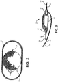
- FIG. 2 shows a cross-sectional view of the roundsling 10 shown in FIG. 1A , taken along line 2-2.
- the cross-section shows the core 12 housed within the cover 14.
- the cross-section also shows the core 12 comprised of a plurality of strands 13.
- the strands 13 may be configured in a plurality of endless parallel loops of strands 13 to form a single core 12 or multiple cores (not shown), all of which are contained inside the cover 14.
- the roundsling 10 comprises a dedicated strand 24 that is associated with the core 12, as described in more detail below.
- the dedicated strand 24 is preferably different from the strands 13 that make up the core 12, and the dedicated strand 24 may be part of a pre-failure indicator assembly 20.
- FIG. 3 A non-limiting example of the pre-failure indicator assembly 20 is shown in FIG. 3 , illustrated as a side view and without the core 12 (shown without the core 12 for illustration purposes).
- the single-path roundsling 10 or the two-path roundsling 10a may comprise a pre-failure indicator assembly 20.
- Each path of a two path roundsling 10a may comprise its own pre-failure indicator assembly 20 and its respective components.
- the pre-failure indicator assembly 20 comprises at least one dedicated strand 24, which comprises a first end 26 and a second end 28.
- the first end 26 comprises a first eye-loop 27, and the second end comprises a second eye-loop 29.
- the first eye-loop 27 and second eye loop 29 are preferably indirectly connected together with a ring 22.
- the ring 22 is between each of the first and second eye-loops 27 and 29, with each eye loop 27 and 29 and the ring 22 forming a chain-like connection.
- the indicator yarn 18 is connected to the pre-failure indicator assembly 20, for example, by connecting the yarn 18 to either the first eye-loop 27 or the second eye loop 29.
- the dedicated strand 24 is preferably made of the same material as the core strands 13, but may be made of a different material in some aspects.
- the pre-failure indicator assembly 20 may be located underneath the cover 14, and may be located underneath the label 16.
- the dedicated strand 24 is preferably placed proximate the core 12, for example, the dedicated strand 24 may be twisted around one or more of the core strands 13, or the dedicated strand 24 may lay next to the core 12, as illustrated in FIG. 2 .
- the dedicated strand 24 is affixed to the inside of the cover 14.
- the cover 14 may develop wear points at specific locations, for example, where the roundsling 10 hangs from a crane's hook. Accordingly, it may be desirable to rotate the cover 14 with respect to the load-bearing core 12.
- movement of the cover 14 (either intentionally or non-intentionally) will not affect the operation of the pre-failure indicator assembly 20.
- the dedicated strand 24 plus the ring 22 form an endless loop.
- the shape of the separate dedicated strand 24 generally matches the shape of the endless parallel loops formed by the core strands 13 (e.g., generally circular or oval).
- the ring 22 may comprise any suitable shape.
- the ring 22 comprises a lower tensile strength than the core 12.
- the ring 22 may be comprise of a different material than the core strands 13, or the ring 22 may comprise a plurality of frangible zones such as cuts or notches in the ring 22 that physically weaken it, or the ring 22 may comprise a smaller diameter than the core strands 13.
- the pre-failure indicator assembly 20 is designed to trigger and thereby notify the rigger or other users of the roundsling 10 that the roundsling 10 has been over-stretched or overloaded (e.g., the roundsling 10 was subjected to a force that compromised its integrity), which may be about four times greater than the rated capacity of the roundsling 10.
- the ring 22 will fail before damage can occur to either the core strands 13 (and therefore, the core 12) or the dedicated strand 24.
- the ring 22 When ring 22 fails, the first eye-loop 27 and the second eye-loop 29 begin moving in opposite directions, away from each other, and the physical distance between these eye-loops 27 and 29, as well as the first and second ends 26 and 28 of the dedicated strand 24 increases.
- the ring 22 will fail at about 70% to about 90% of the tensile strength (e.g., the maximum load-bearing capacity) of the core 12. In some preferred aspects, the ring 22 will fail at about 70%, about 75%, or about 80% of the tensile strength of the core 12.
- the ring 22 is designed to fail before damage occurs to the core 12, thereby warning a user that they must either stop using the roundsling 10 in the manner in which they are using it or, if they continue, the roundsling 10 will be permanently damaged.
- Ring 22 failure includes, but is not limited to, breaking, pulverizing, stretching, or otherwise being compromised such that the ring 22 can no longer bridge the ends of the dedicated strand 24 together, or such that the ends of the dedicated strand 24 can no longer be maintained a certain distance apart.
- the pre-failure indicator assembly 20 includes an indicator yarn 18, as the eye-loops 27 and 29 move apart, the portion of the yarn 18 that extends beyond the label 16 and is visible to the user is drawn back inside the cover label 16 or the cover 14 until its end is no longer visible. If the terminal end of the yarn 18 is not visible, or if the visible end portion is otherwise noticeably shorter, an inspector or rigger will immediately be able to determine that the roundsling 10 may have overextended or overloaded.
- a pre-failure indicator assembly 20 includes a plurality of rings 22.
- the assembly 20 may include three rings, 22a, 22b, and 22c connected together between the first and second eye-loops 27 and 29.
- a two-path roundsling 10a may comprise two pre-failure indicator assemblies 20a and 20b, as shown in FIG. 5 , with one assembly 20 for each sling path.
- the components of each pre-failure indicator assembly 20a and 20b are the same, as described above.
- the roundsling 10 preferably comprises a RFID pre-failure warning system 40.
- the RFID pre-failure warning system 40 generally comprises one or more RFID tags 42, at least one RFID sensor 44, and at least one RFID signal receiver 46.
- the RFID sensor 44 generally functions to detect the RFID tag 42, for example, when the RFID tag 42 is brought into proximity of the RFID sensor 44 or otherwise passes by the RFID sensor 44, and once the RFID tag 42 is detected, the RFID sensor 44 transmits a signal that is to be received by the RFID signal receiver 46.
- the one or more RFID tags 42 may be a passive RFID tag 42, for example, an RFID tag 42 that does not include its own power source, but may include components that generate a current to power the RFID tag 42 when such components are brought into proximity of emissions from the RFID sensor 44.
- the one or more RFID tags 42 may be an active RFID tag 42 or a semi-passive RFID tag 42, which each may include a power source, preferably a battery, to power the RFID tag 42.
- An active RFID tag 42 may utilize its power source to transmit a signal, and a semi-passive RFID tag 42 may use emissions from the RFID sensor 44 to transmit a signal.
- An RFID tag 42 may comprise a shield 43 that blocks the signal, which may be helpful, for example, in an embodiment in which the RFID tag 42 is active, and it is desired to detect the signal only when the shield 43 is compromised as an indicator that one or more components of the roundsling 10 (e.g., core strand 13, core 12, pre-failure indicator assembly 20, ring 22, etc.) have been damaged such that the roundsling 10 is in danger of failure.
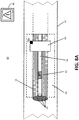
- FIG. 6A through FIG. 6C One non-limiting example of a RFID pre-failure warning system 40 is shown in FIG. 6A through FIG. 6C .
- the RFID pre-failure warning system 40 may be situated at the label 16 area of the roundsling 10 or 10a, although the pre-failure warning system 40 may be positioned anywhere around the circumference of the roundsling 10 or 10a.
- the indicator yarn 18 forms a part of the RFID pre-failure warning system 40, and the RFID tag 42 is affixed to the indicator yarn 18.
- the indicator yarn 18 may, but need not be, connected to a pre-failure indicator assembly 20 (not shown), as described above.
- the RFID sensor 44 comprises a transmitter 43 or transceiver 43 that is capable of emitting a wireless signal, which signal sends information concerning the condition of the roundsling 10.
- the RFID sensor 44 is affixed to the label 16, although the RFID sensor 44 may be affixed to the cover 14, in which case the RFID sensor 44 may be on the interior or exterior of the cover 14, so long as the RFID sensor 44 may detect the RFID tag 42.
- the RFID tag 42 may be affixed at any location in the yarn 18 downstream of the RFID sensor 44 suitable to indicate that the sling 10 is being stressed (downstream in this case refers to a portion of the yarn 18 between the external terminal end and the RFID sensor 44). As shown, the RFID tag 42 is located on a section of the yarn 18 below the label 16.
- the indicator yarn 18 is pulled upstream, with the length of the end portion of the yarn 18 visible from the outside of the roundsling 10 shortening and eventually disappearing from view as the yarn 18 is retracted into the label 16.
- the RFID tag 42 As the yarn 18 is pulled upstream (direction of the arrow), the RFID tag 42 is also pulled upstream, and if the RFID tag 42 is pulled far enough upstream, the RFID tag 42 passes by the RFID sensor 44. When the RFID tag 42 passes by the RFID sensor 44, the RFID sensor 44 sends a warning signal to the RFID signal receiver 46.
- the RFID sensor 44 may send the signal through the transmitter 43 or transceiver 43.
- the signal preferably is a wireless signal.
- the RFID signal receiver 46 may comprise a hand-held device.
- the RFID signal receiver 46 indicates to a user that a warning signal has been triggered, meaning that the roundsling 10 has been overloaded or overstretched and that if the situation is not mitigated or remedied, the roundsling may fail 10.
- the RFID signal receiver 46 may, for example, warn a user through an audible alarm, a visible warning, and/or a tactile alarm such as vibration. Having received the warning signal from the RFID signal receiver 46, the user may take corrective action.
- the RFID pre-failure warning system 40 may comprise a plurality of RFID tags 42.
- a non-limiting example of four RFID tags 42a, 42b, 42c, and 42d is shown in FIG. 6B .
- Any suitable number of RFID tags 42 may be used, including two, three, four, five, six, seven, eight, nine, ten, or more RFID tags 42.
- the end portion of the indicator yarn 18 extends out from the label 16 and is visible outside of the roundsling 10.
- the plurality of RFID tags 42 may be affixed at any locations in the yarn 18 suitable to indicate that the sling 10 is being stressed.
- Each of the plurality of RFID tags 42 may be evenly spaced apart, or may be spaced apart at desired distances that are not necessarily equal among the tags 42.
- the indicator yarn 18 is pulled upstream, with the length of the yarn 18 visible from the outside of the roundsling 10 shortening and eventually disappearing from view as the yarn 18 is retracted into the label 16.
- the plurality of RFID tags 42 is also pulled upstream.
- this RFID tag 42 passes by the RFID sensor 44, and this is repeated for each successive RFID tag 42 until the downstream-most RFID tag 42 passes by the RFID sensor 44.
- Successive downstream RFID tags 42 may indicate progressively higher degrees of overloading or overstretching of the roundsling 10. For example, as the degree of overloading or overstretching increases, the indicator yarn 18 will be pulled further upstream, thereby allowing more and more downstream RFID tags 42 to pass by the RFID sensor 44. In this case, the RFID sensor 44 may send different warning signals to the RFID signal receiver 46. The RFID signal receiver may then indicate to a user the different levels of warning signals that reflect the degree of stress on the roundsling 10. For example, warning signals may range from passing the maximum load capacity or rating for the roundsling 10 up to imminent failure. The RFID signal receiver 46 may, for example, warn a user through an audible alarm, a visible warning, and/or a tactile alarm such as vibration. Having received the warning signal from the RFID signal receiver 46, the user may take corrective action, which may be based on the degree of stress to the roundsling 10.
- the RFID pre-failure warning system 40 may also be used with a two-path roundsling 10a, for example, as shown in FIG. 6C .
- the components of each pre-failure warning system 40 for each sling path are identical, and are shown with an "a" or "b" designation in FIG. 6C .
- FIG. 6C only a single RFID signal receiver 46 is shown, with this receiver 46 capable of receiving a warning signal from either or both of the RFID sensors 44a and 44b.
- the RFID pre-failure warning system 40 used in a two-path roundsling 10a may utilize a plurality of RFID tags 42, as shown in FIG. 6B .
- the RFID pre-failure warning system 40 affixes the RFID tag(s) 42 to the indicator yarn 18. It is not necessary, however, that the RFID tag(s) 42 be affixed to the indicator yarn 18. In some aspects, the RFID tag(s) 42 may be affixed to one or more of the strands 13 of the core 12, as shown in FIG. 7A through FIG. 7C . The RFID tag(s) 42 may be affixed to the core strands 13 in addition to the indicator yarn 18 (if present), or instead of the indicator yarn 18.
- the RFID pre-failure warning system 40 embodiments shown in FIG. 7A through FIG. 7C operate based on the same principles under which the embodiments shown in FIG. 6A through FIG. 6C operate.
- the RFID pre-failure warning system 40 shown in FIG. 7A through FIG. 7C may also be used with a two-path roundsling 10a (not shown).
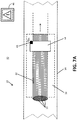
- FIG. 7A a partial cut-away view of a roundsling 10 is shown, with the core 12 exposed (and for purposes of illustrating the core strands 13, a cross-section of the core 12 is also shown) beneath the label 16.
- the RFID tag 42 is affixed to one of the core strands 13 just downstream of the RFID sensor 44 (downstream in this case refers to the left side of the image of the RFID sensor 44).
- downstream in this case refers to the left side of the image of the RFID sensor 44.
- the RFID tag 42 passes by the RFID sensor 44.
- the RFID sensor 44 sends a warning signal to the RFID signal receiver 46.
- the RFID sensor 44 may send the signal through the transmitter 43 or transceiver 43.
- FIG. 7A shows the relative position of the RFID tag 42 to the left side of the RFID sensor 44
- the RFID tag 42 may in the alternative be positioned to the right side of the RFID sensor 44 (not shown), in which case, when the core 12 of the roundsling 10 is overloaded or overstretched, the portion of the strand 13 to which the RFID tag is affixed moves downstream, and if the core 12 moves far enough, the RFID tag 42 passes by the RFID sensor 44, thereby triggering the warning signal.
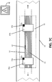
- two RFID sensors 44a and 44b may be used, with one RFID sensor 44a positioned to the left side of the RFID tag 42, and one RFID sensor 44b positioned to the right side of the RFID tag ( Fig. 7C ). This configuration provides for movement of an overstretched or overloaded core 12 in either direction, thereby triggering the warning signal.
- Each RFID sensor 44a and 44b comprises a transmitter 43a and 43b or transceiver 43a and 43b.
- a plurality of RFID tags 42 may be affixed to a core strand 13, as shown in FIG. 7B.
- FIG. 7B shows a non-limiting example of two RFID tags 42, although three, four, five, six, seven, eight, nine, ten, or more RFID tags 42 may be used.
- the plurality of RFID tags 42 may be affixed at any locations in the core strand 13 suitable to indicate that the sling 10 is being stressed.
- Each of the plurality of RFID tags 42 may be evenly spaced apart, or may be spaced apart at desired distances that are not necessarily equal among the tags 42. As the core strands 13 are moved, the plurality of RFID tags 42 is also moved.
- Successive downstream RFID tags 42 may indicate progressively higher degrees of overloading or overstretching of the roundsling 10. For example, as the degree of overloading or overstretching increases, the core strands 13 move further, thereby allowing more and more downstream RFID tags 42 to pass by the RFID sensor 44. In this case, the RFID sensor 44 may send different warning signals to the RFID signal receiver 46. The RFID signal receiver may then indicate to a user the different levels of warning signals that reflect the degree of stress on the roundsling 10. For example, warning signals may range from passing the maximum load capacity or rating for the roundsling 10 up to imminent failure. The RFID signal receiver 46 may, for example, warn a user through an audible alarm, a visible warning, and/or a tactile alarm such as vibration. Having received the warning signal from the RFID signal receiver 46, the user may take corrective action, which may be based on the degree of stress.
- the RFID pre-failure warning system 40 shown in FIG. 7A through FIG. 7C may be used in addition to the RFID pre-failure warning system 40 shown in FIG. 6A through FIG. 6C and shown in FIG. 8A through FIG. 8C , for example, as a form of a redundancy, or may be used independently of such systems, as a stand-alone system.
- the RFID pre-failure warning system 40 shown in FIG. 7A through FIG. 7C may be used with a two-path roundsling 10a, with each path having a set of components of the RFID pre-failure warning system 40.
- the RFID tag(s) 42 are not affixed to the indicator yarn 18 or to the core strands 13, and instead, are affixed to the dedicated strand 24, as shown in FIG. 8A through FIG. 8C .
- the RFID pre-failure warning system 40 embodiments shown in FIG. 8A through FIG. 8C operate based on the same principles under which the embodiments shown in FIG. 6A through FIG. 7C operate.
- FIG. 8A a partial cut-away view of a roundsling 10 is shown, with the core 12 exposed (and for purpose of illustrating the core strands 13 and the dedicated strand 24, a cross-section of the core 12 and the dedicated strand 24 is also shown) beneath the label.
- the RFID tag 42 is affixed to the dedicated strand 24 just downstream of the RFID sensor 44 (downstream in this case refers to the left side of the image of the RFID sensor 44).
- the RFID tag 42 passes by the RFID sensor 44.
- the RFID sensor 44 sends a warning signal to the RFID signal receiver 46.
- the RFID sensor 44 may send the signal through the transmitter 43 or transceiver 43.
- FIG. 8A shows the relative position of the RFID tag 42 to the left side of the RFID sensor 44
- the RFID tag 42 may in the alternative be positioned to the right side of the RFID sensor 44 (not shown), in which case, when the core 12 of the roundsling 10 is overloaded or overstretched, the portion of the dedicated strand 24 to which the RFID tag is affixed moves downstream, and if the dedicated strand 24 moves far enough, the RFID tag 42 passes by the RFID sensor 44, thereby triggering the warning signal.
- two RFID sensors 44a and 44b may be used, with one RFID sensor 44a positioned to the left side of the RFID tag 42, and one RFID sensor 44b positioned to the right side of the RFID tag ( Fig. 8C ). This configuration provides for movement of the dedicated strand 24 in either direction, thereby triggering the warning signal.
- Each RFID sensor 44a and 44b comprises a transmitter 43a and 43b or transceiver 43a and 43b.
- Successive downstream RFID tags 42 may indicate progressively higher degrees of overloading or overstretching of the roundsling 10. For example, as the degree of overloading or overstretching increases, the dedicated strand 24 moves further, thereby allowing more and more RFID tags 42 to pass by the RFID sensor 44. In this case, the RFID sensor 44 may send different warning signals to the RFID signal receiver 46. The RFID signal receiver may then indicate to a user the different levels of warning signals that reflect the degree of stress on the roundsling 10. For example, warning signals may range from passing the maximum load capacity or rating for the roundsling 10 up to imminent failure. The RFID signal receiver 46 may, for example, warn a user through an audible alarm, a visible warning, and/or a tactile alarm such as vibration. Having received the warning signal from the RFID signal receiver 46, the user may take corrective action, which may be based on the degree of stress.
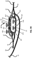
- the pre-failure indicator assembly 20 includes one or more RFID tags 42 ( FIG. 9A and FIG. 9B ).
- the ring 22 comprises the one or more RFID tags 42, for example, as integral with the ring 22 or as affixed to the ring.
- the ring 22 comprises a lower tensile strength than the core 12, or the ring 22 may comprise a plurality of frangible zones such as cuts or notches in the ring 22 that physically weaken it, or the ring 22 may comprise a smaller diameter than the core strands 13.
- the roundsling 10 is placed under a load that exceeds its recommended rating, the ring 22 will fail before the core strands 13, the core 12, or the dedicated strand 24 fails.
- the one or more RFID tags 42 fail such that the RFID sensor 44 sends a warning signal to the RFID signal receiver 46.
- the one or more RFID tags 42 are active RFID tags 42 and, therefore, include their own power source (not shown) that drives the RFID signal.
- the RFID tag 42 continuously transmits a signal, which is detected by the RFID signal receiver 46.
- the RFID signal receiver 46 indicates to a user that the RFID signal is active, and as long as the signal is active, the ring 22 has not failed. But when the ring 22 fails, the RFID tag 42 is compromised such that it can no longer transmit a signal. The cessation of the signal is detected by the RFID signal receiver 46, thereby indicating that the ring 22 has failed.
- the RFID signal receiver 46 may then warn a user through an audible alarm, a visible warning, and/or a tactile alarm such as vibration. Having received the warning signal from the RFID signal receiver 46, the user may take corrective action.
- the one or more RFID tags 42 are active RFID tags 42, but are encased in a shield, for example, an aluminum shield 43 or shield of other suitable material (which are known in the art), that blocks its signal.
- a shield for example, an aluminum shield 43 or shield of other suitable material (which are known in the art), that blocks its signal.
- Each ring 22 may comprise the shield 43.
- the RFID tag 42 continuously transmits a signal, but this signal is blocked such that it is not detected by the RFID signal receiver 46.
- the RFID signal receiver 46 indicates to a user that there is no RFID signal, and as long as the signal is not detected, the ring 22 has not failed. But when the ring 22 fails, the shield 43 of the RFID tag 42 is compromised such that the signal is no longer blocked.
- At least one of the one or more RFID tags 42 is not compromised along with the ring 22 such that the RFID tag 42 may still transmit the signal, which may freely pass through the compromised shield 43.
- the freed signal is detected by the RFID signal receiver 46, thereby indicating that the ring 22 has failed.
- the RFID signal receiver 46 may then warn a user through an audible alarm, a visible warning, and/or a tactile alarm such as vibration. Having received the warning signal from the RFID signal receiver 46, the user may take corrective action.
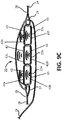
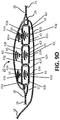
- a pre-failure indicator assembly 20 includes a plurality of rings 22.
- the assembly 20 may include three rings, 22a, 22b, and 22c connected together between the first and second eye-loops 27 and 29.
- Each ring 22 among the plurality of rings 22 may comprise one or more RFID tags 42, which preferably are active RFID tags 42.
- the operation of the warning signal is the same as described above for the single ring 22 embodiment.
- the failure of one or more rings 22 in the plurality may compromise the RFID tag 42, thereby ceasing the RFID signal, indicating that one or more rings 22 have failed.
- the failure of one or more rings 22 in the plurality may compromise the RFID tag shield 43, allowing the RFID signal to pass through the compromised shield 43, thereby allowing the signal to be detected, indicating that one or more rings 22 have failed.
- a two-path roundsling 10a may comprise two pre-failure indicator assemblies 20a and 20b, as shown in FIG. 9E , with one assembly 20 for each sling path.
- the components of each pre-failure indicator assembly 20a and 20b are the same, as described above.
- the operation of the warning signal is the same as described above for the one path roundsling 10.
- the RFID pre-failure warning systems 40 described above are preferably used as a monitoring system during operation of a single-path roundsling 10 or two-path roundsling 10a.
- the RFID pre-failure warning systems 40 may be used, for example, in accordance with a method for detecting a pre-failure condition in a roundsling 10 or 10a.
- the methods comprise detecting a signal transmitted from the RFID sensor 44, for example, using the RFID signal receiver 46.
- the methods may further comprise taking corrective action to avoid, prevent, or mitigate against failure of the roundsling 10 or 10a.
- the corrective action may include, for example, cessation of lifting and returning the material(s) being lifted to a base.
- the corrective action may also include replacing the roundsling 10 or 10a.
Landscapes
- Engineering & Computer Science (AREA)
- Mechanical Engineering (AREA)
- Apparatus For Radiation Diagnosis (AREA)
- Emergency Alarm Devices (AREA)
Description
- The invention relates generally to industrial slings used to lift, move and transport heavy loads and, more particularly, relates to RFID-based warning indicators that notify an operator of the sling of a condition that if not mitigated may lead to failure of the sling.
- Various publications, including patents, published applications, technical articles, and scholarly articles are cited throughout the specification. Each of these materials is incorporated by reference herein, in its entirety and for all purposes.
- Industrial slings are typically prepared from metals or synthetic materials. Wire rope slings are commonly made of a plurality of metal strands twisted together and secured by large metal sleeves or collars. Synthetic slings are usually comprised of a lifting core made of twisted strands of synthetic fiber and an outer cover that protects the core. One popular design of synthetic slings is a roundsling in which the lifting core forms a continuous loop and the sling has a circular or oval-shaped appearance.
- Modern industrial slings may experience failure and loss of a load caused by the sling breaking or failing, for example, because it was fatigued or because it was over-stretched or over-loaded during a current or previous use. When subjected to an overload condition in excess of its rated capacity, a roundsling may be permanently damaged/deformed if the load stretches the fibers of the load bearing core material beyond their yield point. When a synthetic fiber sling is overloaded beyond its tensile strength or weight-lifting capacity at maximum stretch, it is considered to be fatigued and may never return to its normal strength and load bearing capacity.
- Slings are generally provided with their load capacity (rated capacity) specified, particular sling. This allows users to know the lifting or load capacity of the sling. Nevertheless, this capacity is sometimes exceeded, either accidentally or by users engaging unsafe shortcuts during rigging and use of the sling. Often, over-load, fatigue, or damage to the sling materials may not be readily apparent, particularly given the large size or length of the sling, or because the load-bearing core is hidden inside the outer cover. If a roundsling has been fatigued or structurally changed, the sling may no longer be able to lift a load according to its maximum rated load capacity. Such a condition may potentially become a serious threat to the operators and riggers using the damaged sling.
- Many commercially produced roundslings include a pre-failure indicator.
U.S. Pat. No. 7,661,737 discloses a pre-failure indicator or a system according to the preamble of theindependent claims 1, 9 and 15. Such failure indicators in practice have shown to be inconsistent, even among the same types of slings from the same manufacturer. Accordingly, there is a need in the art for more consistent and more reliable sling pre-failure indicators. This is achieved by the roundsling pre-failure warning systems according to theindependent claims 1, 9 and 15, as well as by the method according to the independent claim 17. - The disclosure features roundsling pre-failure warning systems. In some aspects, the systems comprise a roundsling comprising a load-bearing core, an indicator yarn comprising at least one radio frequency identification (RFID) tag affixed to the indicator yarn, and one or more RFID sensors comprising a transmitter for sending a wireless signal to a RFID signal receiver, and also comprise a RFID signal receiver. The systems may further comprise a pre-failure indicator assembly comprising a dedicated strand having an eye-loop on each end joined together via one or more rings that fail at a load capacity that is less than the maximum load capacity of the load-bearing core. The dedicated strand is preferably positioned proximate to the core. The indicator yarn is preferably connected to the dedicated strand. The indicator yarn is preferably brightly colored in order to be readily visible to operators or the roundsling. The RFID signal receiver may comprise hand-held wireless device such as a cellular telephone, tablet computer, or other form of wireless computer, and informs a user of a pre-failure condition with the roundsling by one or more of emitting an audible alarm, displaying a visible warning, and/or producing a tactile alarm.
- In some aspects, the core is housed within a cover having an opening through which an end portion of the indicator yarn passes, thereby exposing the end portion of the indicator yarn to the exterior of the cover. The RFID tag may be affixed to a location about the visible/exterior end portion of the indicator yarn. The RFID sensor may be proximate to the opening. The indicator yarn may comprise a plurality of RFID tags, or may comprise at least two, at least three, or at least four, or more than four RFID tags.
- The roundsling may be a one-path or two-path roundsling. In certain two-path roundslings, each path comprises a load-bearing core, an indicator yarn comprising one or more RFID tags affixed to the indicator yarn, and one or more RFID sensors comprising a transmitter for sending a wireless signal to a RFID signal receiver. Each path may further comprise a pre-failure indicator assembly comprising a dedicated strand having an eye-loop on each end joined together via one or more rings that fail at a load capacity that is less than the maximum load capacity of the load-bearing core. The dedicated strand is preferably positioned proximate to the core. The indicator yarn is preferably connected to the dedicated strand. The indicator yarn is preferably brightly colored in order to be readily visible to operators or the roundsling.
- In some aspects, the systems comprise a roundsling comprising a load-bearing core, a pre-failure indicator assembly comprising a dedicated strand positioned proximate to the core and having an eye-loop on each end joined together via one or more rings that fail at a load capacity that is less than the maximum load capacity of the load-bearing core, and having one or more RFID tags affixed to the dedicated strand, and one or more RFID sensors comprising a transmitter for sending a wireless signal to a RFID signal receiver, and a RFID signal receiver. The RFID signal receiver may comprise hand-held wireless device such as a cellular telephone, tablet computer, or other form of wireless computer, and informs a user of a pre-failure condition with the roundsling by one or more of emitting an audible alarm, displaying a visible warning, and/or producing a tactile alarm.
- In some aspects, the systems comprise a roundsling comprising a load-bearing core, a pre-failure indicator assembly comprising a dedicated strand having an eye-loop on each end joined together via one or more rings that fail at a load capacity that is less than the maximum load capacity of the load-bearing core. The ring preferably comprises one or more active RFID tags. The one or more RFID tags may optionally comprise a shield that blocks the signal transmitted from the RFID tag. If the shield is compromised, the signal may escape through the compromised area and the freed signal may be detected. Optionally, the systems may comprise an indicator yarn connected to the dedicated strand. The systems also comprise a RFID signal receiver.
- The dedicated strand may comprise a plurality of RFID tags, or may comprise at least two, at least three, or at least four, or more than four RFID tags. The roundsling may comprise two or more RFID sensors. An indicator yarn may be attached to the dedicated strand, with an end portion of the indicator yarn exposed to the exterior of the cover.
- The roundsling may be a one-path or two-path roundsling. In certain two-path roundslings, each path comprises a load-bearing core, a pre-failure indicator assembly comprising a dedicated strand positioned proximate to the core and having an eye-loop on each end joined together via one or more rings that fail at a load capacity that is less than the maximum load capacity of the load-bearing core, and having one or more RFID tags affixed to the dedicated strand, and one or more RFID sensors comprising a transmitter for sending a wireless signal to a RFID signal receiver.
- The invention is best understood from the following detailed description when read in connection with the accompanying drawings. It is emphasized that, according to common practice, the various features of the drawings are not to scale. On the contrary, the dimensions of the various features are arbitrarily expanded or reduced for clarity. Included in the drawings are the following figures:
-
FIG. 1A shows a single-path roundsling having a pre-failure warning indicator;FIG. 1B shows a two-path roundsling having a pre-failure warning indicator; -
FIG. 2 shows a cross-sectional view of a protective cover and load-bearing core of a roundsling; -
FIG. 3 shows a pre-failure indicator assembly; -
FIG. 4 shows a pre-failure indicator assembly utilizing multiple deforming rings linked together; -
FIG. 5 shows a pre-failure indicator assembly for a two-path sling; -
FIG. 6A shows a pre-failure RFID warning indicator system for a single-path roundsling;FIG. 6B shows a pre-failure RFID warning indicator system for a single-path roundsling, having a plurality of RFID tags;FIG. 6C shows a pre-failure RFID warning indicator system for a two-path roundsling; -
FIG. 7A shows a RFID tag affixed to a strand of the roundsling core;FIG. 7B shows a plurality of RFID tags affixed to a strand of the roundsling core;FIG. 7C shows two RFID sensors flanking an RFID tag affixed to a core strand; -
FIG. 8A shows a RFID tag affixed to the dedicated strand;FIG. 8B shows a plurality of RFID tags affixed to the dedicated strand;FIG. 8C shows two RFID sensors flanking an RFID tag affixed to the dedicated strand; -
FIG. 9A shows a pre-failure indicator assembly using a single deforming ring comprising one or more large RFID tags;FIG. 9B shows a pre-failure indicator assembly using a single deforming ring comprising a plurality of small RFID tags around the perimeter of the ring, and shows an optional RFID tag shield;FIG. 9C shows a pre-failure indicator assembly as shown inFIG. 9A , but which employs multiple deforming rings comprising an RFID tag;FIG. 9D shows a pre-failure indicator assembly as shown inFIG. 9B , but which employs multiple deforming rings comprising an RFID tag; and,FIG. 9E shows a pre-failure indicator assembly as shown inFig. 9A for a two-path sling. - Various terms relating to aspects of disclosure are used throughout the specification and claims. Such terms are to be given their ordinary meaning in the art, unless otherwise indicated. Other specifically defined terms are to be construed in a manner consistent with the definition provided herein.
- The disclosure relates to systems and methods for determining whether an industrial roundsling may fail during use, for example, because load-bearing aspects of the roundsling have been overstretched or overloaded. A foundational feature includes radio frequency identification tags and sensors that convey information about the condition of the load-bearing aspects of the roundsling to a user. The roundslings may comprise the roundslings and the sacrificial ring-based pre-failure indicator systems of
U.S. Pat. No. 7,661,737 . -
FIG. 1A illustrates one non-limiting example of a single-path roundsling 10. The single-path roundsling 10 comprises a load-bearing core 12. The core 12 may be comprised of a plurality of strands 13 (FIG. 2 ), that may be fabricated from any suitable material, including metal or synthetic polymers or composite materials. The core 12 may comprise one or more natural or synthetic materials, such as polyester, polyethylene, nylon, K-Spec® (SlingMax, Inc., comprising a proprietary blend of fibers), high-modulus polyethylene (HMPE), liquid crystal polymer (LCP), aramid, para-aramid, or other suitable synthetic material. The material of the core 12 may relate to the maximum weight thesling 10 is designed to lift, and the environment in which thesling 10 will be used. In general,synthetic strands 13 have a high lifting and break strength, lighter weight, high temperature resistance and high durability, compared to wire rope or metal chain slings. - The
core 12 is housed within aprotective cover 14. The core 12 generally bears substantially the entire weight of the load to be lifted. Thecover 14 generally prevents physical damage to thecore 12, for example from abrasion, and sharp edges on the load, as well as protects the core 12 from exposure to harsh environmental conditions such as heat, humidity, ultraviolet light, corrosive chemicals, gaseous materials, or other environmental conditions that may damage or weaken the core 12 materials. - The single-
path roundsling 10 may also comprise anindicator yarn 18, as well as alabel 16. Thecover 14 may comprise an opening through which theindicator yarn 18 may pass through, with a length of theyarn 18 and one terminal end thus located inside of thecover 14, and a length of theyarn 18 and the other terminal end thus located outside of thecover 14. The opening may be located underneath thelabel 16, but may be located at any suitable position in thecover 14. In aspects where the opening is positioned beneath thelabel 16, theyarn 18 may extend out from thelabel 16, with a length of one end portion extending freely beyond the surface of thecover 14. Theyarn 18 preferably is of a bright color, including yellow, orange, red, or a combination thereof, or other suitable visible or contrasting color so that a user may monitor the visible end portion of theyarn 18. For example, in the event that theroundsling 10 is overstretched or overloaded, the visible portion of theyarn 18 may become shorter as theyarn 18 is pulled into thelabel 16, with the shortening of the visible section of theyarn 18 signaling the user that theroundsling 10 is overstretched or overloaded. In this sense, theindicator yarn 18 may serve as a redundancy for some embodiments of the RFIDpre-failure warning systems 40 described below. As well, theindicator yarn 18 may comprise a component ofsuch systems 40. -
FIG. 1B illustrates one non-limiting example of a two-path roundsling 10a. The basic features of a single-path roundsling 10 and a two-path roundsling 10a are generally the same, as shown inFIG. 1A and FIG. 1B . Thus, for example, a two-path roundsling 10a comprises two separate load-bearing cores 12 and 12a, twoseparate covers separate labels separate indicator yarns -
FIG. 2 shows a cross-sectional view of theroundsling 10 shown inFIG. 1A , taken along line 2-2. The cross-section shows the core 12 housed within thecover 14. The cross-section also shows the core 12 comprised of a plurality ofstrands 13. Thestrands 13 may be configured in a plurality of endless parallel loops ofstrands 13 to form asingle core 12 or multiple cores (not shown), all of which are contained inside thecover 14. In some preferred aspects, theroundsling 10 comprises adedicated strand 24 that is associated with thecore 12, as described in more detail below. Thededicated strand 24 is preferably different from thestrands 13 that make up thecore 12, and thededicated strand 24 may be part of apre-failure indicator assembly 20. - A non-limiting example of the
pre-failure indicator assembly 20 is shown inFIG. 3 , illustrated as a side view and without the core 12 (shown without thecore 12 for illustration purposes). The single-path roundsling 10 or the two-path roundsling 10a may comprise apre-failure indicator assembly 20. Each path of a twopath roundsling 10a may comprise its ownpre-failure indicator assembly 20 and its respective components. - The
pre-failure indicator assembly 20 comprises at least onededicated strand 24, which comprises afirst end 26 and asecond end 28. Thefirst end 26 comprises a first eye-loop 27, and the second end comprises a second eye-loop 29. The first eye-loop 27 andsecond eye loop 29 are preferably indirectly connected together with aring 22. Thering 22 is between each of the first and second eye-loops eye loop ring 22 forming a chain-like connection. In some aspects, theindicator yarn 18 is connected to thepre-failure indicator assembly 20, for example, by connecting theyarn 18 to either the first eye-loop 27 or thesecond eye loop 29. Thededicated strand 24 is preferably made of the same material as thecore strands 13, but may be made of a different material in some aspects. - The
pre-failure indicator assembly 20 may be located underneath thecover 14, and may be located underneath thelabel 16. Thededicated strand 24 is preferably placed proximate thecore 12, for example, thededicated strand 24 may be twisted around one or more of thecore strands 13, or thededicated strand 24 may lay next to thecore 12, as illustrated inFIG. 2 . In some aspects, thededicated strand 24 is affixed to the inside of thecover 14. When aroundsling 10 is used over a period of time, thecover 14 may develop wear points at specific locations, for example, where theroundsling 10 hangs from a crane's hook. Accordingly, it may be desirable to rotate thecover 14 with respect to the load-bearing core 12. By securing thededicated strand 24 to thecover 14 interior, movement of the cover 14 (either intentionally or non-intentionally) will not affect the operation of thepre-failure indicator assembly 20. - When the first eye-
loop 27 and second eye-loop 29 are connected together via thering 22, thededicated strand 24 plus thering 22 form an endless loop. The shape of the separatededicated strand 24 generally matches the shape of the endless parallel loops formed by the core strands 13 (e.g., generally circular or oval). Thering 22 may comprise any suitable shape. - Preferably, the
ring 22 comprises a lower tensile strength than thecore 12. For example, thering 22 may be comprise of a different material than thecore strands 13, or thering 22 may comprise a plurality of frangible zones such as cuts or notches in thering 22 that physically weaken it, or thering 22 may comprise a smaller diameter than thecore strands 13. - The
pre-failure indicator assembly 20 is designed to trigger and thereby notify the rigger or other users of theroundsling 10 that theroundsling 10 has been over-stretched or overloaded (e.g., theroundsling 10 was subjected to a force that compromised its integrity), which may be about four times greater than the rated capacity of theroundsling 10. When theroundsling 10 is placed under a load that exceeds its recommended rating, thering 22 will fail before damage can occur to either the core strands 13 (and therefore, the core 12) or thededicated strand 24. Whenring 22 fails, the first eye-loop 27 and the second eye-loop 29 begin moving in opposite directions, away from each other, and the physical distance between these eye-loops dedicated strand 24 increases. In some aspects, thering 22 will fail at about 70% to about 90% of the tensile strength (e.g., the maximum load-bearing capacity) of thecore 12. In some preferred aspects, thering 22 will fail at about 70%, about 75%, or about 80% of the tensile strength of thecore 12. In general, thering 22 is designed to fail before damage occurs to thecore 12, thereby warning a user that they must either stop using theroundsling 10 in the manner in which they are using it or, if they continue, theroundsling 10 will be permanently damaged.Ring 22 failure includes, but is not limited to, breaking, pulverizing, stretching, or otherwise being compromised such that thering 22 can no longer bridge the ends of thededicated strand 24 together, or such that the ends of thededicated strand 24 can no longer be maintained a certain distance apart. - In aspects where the
pre-failure indicator assembly 20 includes anindicator yarn 18, as the eye-loops yarn 18 that extends beyond thelabel 16 and is visible to the user is drawn back inside thecover label 16 or thecover 14 until its end is no longer visible. If the terminal end of theyarn 18 is not visible, or if the visible end portion is otherwise noticeably shorter, an inspector or rigger will immediately be able to determine that theroundsling 10 may have overextended or overloaded. - In some aspects, a
pre-failure indicator assembly 20 includes a plurality ofrings 22. For example, as shown inFIG. 4 , theassembly 20 may include three rings, 22a, 22b, and 22c connected together between the first and second eye-loops path roundsling 10a may comprise twopre-failure indicator assemblies FIG. 5 , with oneassembly 20 for each sling path. The components of eachpre-failure indicator assembly - The
roundsling 10 preferably comprises a RFIDpre-failure warning system 40. The RFIDpre-failure warning system 40 generally comprises one or more RFID tags 42, at least oneRFID sensor 44, and at least oneRFID signal receiver 46. TheRFID sensor 44 generally functions to detect theRFID tag 42, for example, when theRFID tag 42 is brought into proximity of theRFID sensor 44 or otherwise passes by theRFID sensor 44, and once theRFID tag 42 is detected, theRFID sensor 44 transmits a signal that is to be received by theRFID signal receiver 46. The one or more RFID tags 42 may be apassive RFID tag 42, for example, anRFID tag 42 that does not include its own power source, but may include components that generate a current to power theRFID tag 42 when such components are brought into proximity of emissions from theRFID sensor 44. The one or more RFID tags 42 may be anactive RFID tag 42 or asemi-passive RFID tag 42, which each may include a power source, preferably a battery, to power theRFID tag 42. Anactive RFID tag 42 may utilize its power source to transmit a signal, and asemi-passive RFID tag 42 may use emissions from theRFID sensor 44 to transmit a signal. AnRFID tag 42 may comprise ashield 43 that blocks the signal, which may be helpful, for example, in an embodiment in which theRFID tag 42 is active, and it is desired to detect the signal only when theshield 43 is compromised as an indicator that one or more components of the roundsling 10 (e.g.,core strand 13,core 12,pre-failure indicator assembly 20,ring 22, etc.) have been damaged such that theroundsling 10 is in danger of failure. - One non-limiting example of a RFID
pre-failure warning system 40 is shown inFIG. 6A through FIG. 6C . As shown inFIG. 6A , the RFIDpre-failure warning system 40 may be situated at thelabel 16 area of theroundsling pre-failure warning system 40 may be positioned anywhere around the circumference of theroundsling indicator yarn 18 forms a part of the RFIDpre-failure warning system 40, and theRFID tag 42 is affixed to theindicator yarn 18. Theindicator yarn 18 may, but need not be, connected to a pre-failure indicator assembly 20 (not shown), as described above. TheRFID sensor 44 comprises atransmitter 43 ortransceiver 43 that is capable of emitting a wireless signal, which signal sends information concerning the condition of theroundsling 10. Preferably, theRFID sensor 44 is affixed to thelabel 16, although theRFID sensor 44 may be affixed to thecover 14, in which case theRFID sensor 44 may be on the interior or exterior of thecover 14, so long as theRFID sensor 44 may detect theRFID tag 42. - When the
roundsling 10 is not overloaded or overstretched, an end portion of theindicator yarn 18 extends out from thelabel 16 and is visible outside of theroundsling 10. TheRFID tag 42 may be affixed at any location in theyarn 18 downstream of theRFID sensor 44 suitable to indicate that thesling 10 is being stressed (downstream in this case refers to a portion of theyarn 18 between the external terminal end and the RFID sensor 44). As shown, theRFID tag 42 is located on a section of theyarn 18 below thelabel 16. When theroundsling 10 is overloaded or overstretched, theindicator yarn 18 is pulled upstream, with the length of the end portion of theyarn 18 visible from the outside of theroundsling 10 shortening and eventually disappearing from view as theyarn 18 is retracted into thelabel 16. As theyarn 18 is pulled upstream (direction of the arrow), theRFID tag 42 is also pulled upstream, and if theRFID tag 42 is pulled far enough upstream, theRFID tag 42 passes by theRFID sensor 44. When theRFID tag 42 passes by theRFID sensor 44, theRFID sensor 44 sends a warning signal to theRFID signal receiver 46. TheRFID sensor 44 may send the signal through thetransmitter 43 ortransceiver 43. The signal preferably is a wireless signal. - The
RFID signal receiver 46 may comprise a hand-held device. TheRFID signal receiver 46 indicates to a user that a warning signal has been triggered, meaning that theroundsling 10 has been overloaded or overstretched and that if the situation is not mitigated or remedied, the roundsling may fail 10. TheRFID signal receiver 46 may, for example, warn a user through an audible alarm, a visible warning, and/or a tactile alarm such as vibration. Having received the warning signal from theRFID signal receiver 46, the user may take corrective action. - In some aspects, the RFID
pre-failure warning system 40 may comprise a plurality of RFID tags 42. A non-limiting example of fourRFID tags FIG. 6B . Any suitable number of RFID tags 42 may be used, including two, three, four, five, six, seven, eight, nine, ten, or more RFID tags 42. - As for an embodiment in which one
RFID tag 42 is used (e.g.,FIG. 6A ), in embodiments in which a plurality of RFID tags 42 is used, when theroundsling 10 is not overloaded or overstretched, the end portion of theindicator yarn 18 extends out from thelabel 16 and is visible outside of theroundsling 10. The plurality of RFID tags 42 may be affixed at any locations in theyarn 18 suitable to indicate that thesling 10 is being stressed. Each of the plurality of RFID tags 42 may be evenly spaced apart, or may be spaced apart at desired distances that are not necessarily equal among thetags 42. When theroundsling 10 is overloaded or overstretched, theindicator yarn 18 is pulled upstream, with the length of theyarn 18 visible from the outside of theroundsling 10 shortening and eventually disappearing from view as theyarn 18 is retracted into thelabel 16. As theyarn 18 is pulled upstream (direction of the arrow), the plurality of RFID tags 42 is also pulled upstream. When theRFID tag 42 most proximal to theRFID sensor 44 is pulled far enough upstream, thisRFID tag 42 passes by theRFID sensor 44, and this is repeated for eachsuccessive RFID tag 42 until thedownstream-most RFID tag 42 passes by theRFID sensor 44. - Successive downstream RFID tags 42 may indicate progressively higher degrees of overloading or overstretching of the
roundsling 10. For example, as the degree of overloading or overstretching increases, theindicator yarn 18 will be pulled further upstream, thereby allowing more and more downstream RFID tags 42 to pass by theRFID sensor 44. In this case, theRFID sensor 44 may send different warning signals to theRFID signal receiver 46. The RFID signal receiver may then indicate to a user the different levels of warning signals that reflect the degree of stress on theroundsling 10. For example, warning signals may range from passing the maximum load capacity or rating for theroundsling 10 up to imminent failure. TheRFID signal receiver 46 may, for example, warn a user through an audible alarm, a visible warning, and/or a tactile alarm such as vibration. Having received the warning signal from theRFID signal receiver 46, the user may take corrective action, which may be based on the degree of stress to theroundsling 10. - The RFID
pre-failure warning system 40 may also be used with a two-path roundsling 10a, for example, as shown inFIG. 6C . The components of eachpre-failure warning system 40 for each sling path are identical, and are shown with an "a" or "b" designation inFIG. 6C . In thesystem 40 shown inFIG. 6C , only a singleRFID signal receiver 46 is shown, with thisreceiver 46 capable of receiving a warning signal from either or both of theRFID sensors pre-failure warning system 40 used in a two-path roundsling 10a may utilize a plurality of RFID tags 42, as shown inFIG. 6B . - In
FIG. 6A through FIG. 6C , the RFIDpre-failure warning system 40 affixes the RFID tag(s) 42 to theindicator yarn 18. It is not necessary, however, that the RFID tag(s) 42 be affixed to theindicator yarn 18. In some aspects, the RFID tag(s) 42 may be affixed to one or more of thestrands 13 of the core 12, as shown inFIG. 7A through FIG. 7C . The RFID tag(s) 42 may be affixed to thecore strands 13 in addition to the indicator yarn 18 (if present), or instead of theindicator yarn 18. The RFIDpre-failure warning system 40 embodiments shown inFIG. 7A through FIG. 7C operate based on the same principles under which the embodiments shown inFIG. 6A through FIG. 6C operate. The RFIDpre-failure warning system 40 shown inFIG. 7A through FIG. 7C may also be used with a two-path roundsling 10a (not shown). - In
FIG. 7A , a partial cut-away view of aroundsling 10 is shown, with the core 12 exposed (and for purposes of illustrating thecore strands 13, a cross-section of thecore 12 is also shown) beneath thelabel 16. As shown, theRFID tag 42 is affixed to one of thecore strands 13 just downstream of the RFID sensor 44 (downstream in this case refers to the left side of the image of the RFID sensor 44). When thecore 12 of theroundsling 10 is overloaded or overstretched, the portion of thestrand 13 to which the RFID tag is affixed moves upstream, and if the core 12 moves far enough, theRFID tag 42 passes by theRFID sensor 44. When theRFID tag 42 passes by theRFID sensor 44, theRFID sensor 44 sends a warning signal to theRFID signal receiver 46. TheRFID sensor 44 may send the signal through thetransmitter 43 ortransceiver 43. - Although
FIG. 7A shows the relative position of theRFID tag 42 to the left side of theRFID sensor 44, theRFID tag 42 may in the alternative be positioned to the right side of the RFID sensor 44 (not shown), in which case, when thecore 12 of theroundsling 10 is overloaded or overstretched, the portion of thestrand 13 to which the RFID tag is affixed moves downstream, and if the core 12 moves far enough, theRFID tag 42 passes by theRFID sensor 44, thereby triggering the warning signal. Similarly, twoRFID sensors RFID sensor 44a positioned to the left side of theRFID tag 42, and oneRFID sensor 44b positioned to the right side of the RFID tag (Fig. 7C ). This configuration provides for movement of an overstretched oroverloaded core 12 in either direction, thereby triggering the warning signal. EachRFID sensor transmitter transceiver - In some aspects, a plurality of RFID tags 42 may be affixed to a
core strand 13, as shown inFIG. 7B. FIG. 7B shows a non-limiting example of twoRFID tags 42, although three, four, five, six, seven, eight, nine, ten, or more RFID tags 42 may be used. The plurality of RFID tags 42 may be affixed at any locations in thecore strand 13 suitable to indicate that thesling 10 is being stressed. Each of the plurality of RFID tags 42 may be evenly spaced apart, or may be spaced apart at desired distances that are not necessarily equal among thetags 42. As thecore strands 13 are moved, the plurality of RFID tags 42 is also moved. When theRFID tag 42 most proximal to theRFID sensor 44 is moved far enough, thisRFID tag 42 passes by theRFID sensor 44, and this is repeated for eachsuccessive RFID tag 42 until theRFID tag 42 originally located most distally from theRFID sensor 44 passes by theRFID sensor 44. - Successive downstream RFID tags 42 may indicate progressively higher degrees of overloading or overstretching of the
roundsling 10. For example, as the degree of overloading or overstretching increases, thecore strands 13 move further, thereby allowing more and more downstream RFID tags 42 to pass by theRFID sensor 44. In this case, theRFID sensor 44 may send different warning signals to theRFID signal receiver 46. The RFID signal receiver may then indicate to a user the different levels of warning signals that reflect the degree of stress on theroundsling 10. For example, warning signals may range from passing the maximum load capacity or rating for theroundsling 10 up to imminent failure. TheRFID signal receiver 46 may, for example, warn a user through an audible alarm, a visible warning, and/or a tactile alarm such as vibration. Having received the warning signal from theRFID signal receiver 46, the user may take corrective action, which may be based on the degree of stress. - The RFID
pre-failure warning system 40 shown inFIG. 7A through FIG. 7C may be used in addition to the RFIDpre-failure warning system 40 shown inFIG. 6A through FIG. 6C and shown inFIG. 8A through FIG. 8C , for example, as a form of a redundancy, or may be used independently of such systems, as a stand-alone system. The RFIDpre-failure warning system 40 shown inFIG. 7A through FIG. 7C may be used with a two-path roundsling 10a, with each path having a set of components of the RFIDpre-failure warning system 40. - In some aspects, the RFID tag(s) 42 are not affixed to the
indicator yarn 18 or to thecore strands 13, and instead, are affixed to thededicated strand 24, as shown inFIG. 8A through FIG. 8C . The RFIDpre-failure warning system 40 embodiments shown inFIG. 8A through FIG. 8C operate based on the same principles under which the embodiments shown inFIG. 6A through FIG. 7C operate. - In
FIG. 8A , a partial cut-away view of aroundsling 10 is shown, with the core 12 exposed (and for purpose of illustrating thecore strands 13 and thededicated strand 24, a cross-section of thecore 12 and thededicated strand 24 is also shown) beneath the label. As shown, theRFID tag 42 is affixed to thededicated strand 24 just downstream of the RFID sensor 44 (downstream in this case refers to the left side of the image of the RFID sensor 44). When thecore 12 of theroundsling 10 is overloaded or overstretched, the ring 22 (not shown) to which thededicated strand 24 is attached becomes compromised, thereby allowing thededicated strand 24 to move upstream, and if thededicated strand 24 moves far enough, theRFID tag 42 passes by theRFID sensor 44. When theRFID tag 42 passes by theRFID sensor 44, theRFID sensor 44 sends a warning signal to theRFID signal receiver 46. TheRFID sensor 44 may send the signal through thetransmitter 43 ortransceiver 43. - Although
FIG. 8A shows the relative position of theRFID tag 42 to the left side of theRFID sensor 44, theRFID tag 42 may in the alternative be positioned to the right side of the RFID sensor 44 (not shown), in which case, when thecore 12 of theroundsling 10 is overloaded or overstretched, the portion of thededicated strand 24 to which the RFID tag is affixed moves downstream, and if thededicated strand 24 moves far enough, theRFID tag 42 passes by theRFID sensor 44, thereby triggering the warning signal. Similarly, twoRFID sensors RFID sensor 44a positioned to the left side of theRFID tag 42, and oneRFID sensor 44b positioned to the right side of the RFID tag (Fig. 8C ). This configuration provides for movement of thededicated strand 24 in either direction, thereby triggering the warning signal. EachRFID sensor transmitter transceiver - In some aspects, a plurality of RFID tags 42 may be affixed to the
dedicated strand 24, as shown inFIG. 8B. FIG. 8B shows a non-limiting example of twoRFID tags 42, although three, four, five, six, seven, eight, nine, ten, or more RFID tags 42 may be used. The plurality of RFID tags 42 may be affixed at any locations in thededicated strand 24 suitable to indicate that theroundsling 10 is being stressed. Each of the plurality of RFID tags 42 may be evenly spaced apart, or may be spaced apart at desired distances that are not necessarily equal among thetags 42. As thededicated strand 24 moves, the plurality of RFID tags 42 affixed to thededicated strand 24 also moves. When theRFID tag 42 most proximal to theRFID sensor 44 is moved far enough, thisRFID tag 42 passes by theRFID sensor 44, and this is repeated for eachsuccessive RFID tag 42 until theRFID tag 42 originally located most distally from theRFID sensor 44 passes by theRFID sensor 44. - Successive downstream RFID tags 42 may indicate progressively higher degrees of overloading or overstretching of the
roundsling 10. For example, as the degree of overloading or overstretching increases, thededicated strand 24 moves further, thereby allowing more and more RFID tags 42 to pass by theRFID sensor 44. In this case, theRFID sensor 44 may send different warning signals to theRFID signal receiver 46. The RFID signal receiver may then indicate to a user the different levels of warning signals that reflect the degree of stress on theroundsling 10. For example, warning signals may range from passing the maximum load capacity or rating for theroundsling 10 up to imminent failure. TheRFID signal receiver 46 may, for example, warn a user through an audible alarm, a visible warning, and/or a tactile alarm such as vibration. Having received the warning signal from theRFID signal receiver 46, the user may take corrective action, which may be based on the degree of stress. - In some aspects, the
pre-failure indicator assembly 20 includes one or more RFID tags 42 (FIG. 9A andFIG. 9B ). Preferably, thering 22 comprises the one or more RFID tags 42, for example, as integral with thering 22 or as affixed to the ring. As described above, thering 22 comprises a lower tensile strength than the core 12, or thering 22 may comprise a plurality of frangible zones such as cuts or notches in thering 22 that physically weaken it, or thering 22 may comprise a smaller diameter than thecore strands 13. When theroundsling 10 is placed under a load that exceeds its recommended rating, thering 22 will fail before thecore strands 13, thecore 12, or thededicated strand 24 fails. When thering 22 fails, the one or more RFID tags 42 fail such that theRFID sensor 44 sends a warning signal to theRFID signal receiver 46. - In such aspects, it is preferable that the one or more RFID tags 42 are active RFID tags 42 and, therefore, include their own power source (not shown) that drives the RFID signal. In one embodiment, the
RFID tag 42 continuously transmits a signal, which is detected by theRFID signal receiver 46. In this case, theRFID signal receiver 46 indicates to a user that the RFID signal is active, and as long as the signal is active, thering 22 has not failed. But when thering 22 fails, theRFID tag 42 is compromised such that it can no longer transmit a signal. The cessation of the signal is detected by theRFID signal receiver 46, thereby indicating that thering 22 has failed. TheRFID signal receiver 46 may then warn a user through an audible alarm, a visible warning, and/or a tactile alarm such as vibration. Having received the warning signal from theRFID signal receiver 46, the user may take corrective action. - In one embodiment, the one or more RFID tags 42 are active RFID tags 42, but are encased in a shield, for example, an
aluminum shield 43 or shield of other suitable material (which are known in the art), that blocks its signal. Eachring 22 may comprise theshield 43. Thus, theRFID tag 42 continuously transmits a signal, but this signal is blocked such that it is not detected by theRFID signal receiver 46. In this case, theRFID signal receiver 46 indicates to a user that there is no RFID signal, and as long as the signal is not detected, thering 22 has not failed. But when thering 22 fails, theshield 43 of theRFID tag 42 is compromised such that the signal is no longer blocked. In this embodiment, at least one of the one or more RFID tags 42 is not compromised along with thering 22 such that theRFID tag 42 may still transmit the signal, which may freely pass through the compromisedshield 43. The freed signal is detected by theRFID signal receiver 46, thereby indicating that thering 22 has failed. TheRFID signal receiver 46 may then warn a user through an audible alarm, a visible warning, and/or a tactile alarm such as vibration. Having received the warning signal from theRFID signal receiver 46, the user may take corrective action. - In some aspects, a
pre-failure indicator assembly 20 includes a plurality ofrings 22. For example, as shown inFIG. 9C andFIG. 9D , theassembly 20 may include three rings, 22a, 22b, and 22c connected together between the first and second eye-loops ring 22 among the plurality ofrings 22 may comprise one or more RFID tags 42, which preferably are active RFID tags 42. When a plurality ofrings 22 is employed, the operation of the warning signal is the same as described above for thesingle ring 22 embodiment. For example, the failure of one ormore rings 22 in the plurality may compromise theRFID tag 42, thereby ceasing the RFID signal, indicating that one ormore rings 22 have failed. Alternatively, the failure of one ormore rings 22 in the plurality may compromise theRFID tag shield 43, allowing the RFID signal to pass through the compromisedshield 43, thereby allowing the signal to be detected, indicating that one ormore rings 22 have failed. - A two-
path roundsling 10a may comprise twopre-failure indicator assemblies FIG. 9E , with oneassembly 20 for each sling path. The components of eachpre-failure indicator assembly path roundsling 10. - The RFID
pre-failure warning systems 40 described above are preferably used as a monitoring system during operation of a single-path roundsling 10 or two-path roundsling 10a. The RFIDpre-failure warning systems 40 may be used, for example, in accordance with a method for detecting a pre-failure condition in aroundsling RFID sensor 44, for example, using theRFID signal receiver 46. The methods may further comprise taking corrective action to avoid, prevent, or mitigate against failure of theroundsling roundsling - The disclosure is not limited to the embodiments described and exemplified above, but is capable of variation and modification within the scope of the appended claims.
Claims (19)
- A roundsling pre-failure warning system, comprising;
a roundsling (10) comprising a loadbearing core (12), characterized by:an indicator yarn (18) having at least one radio frequency identification (RFID) tag (42) affixed to the indicator yarn (18),at least one RFID sensor (44) including a transmitter (43), anda RFID signal receiver (46), the transmitter (43) for sending a wireless signal to the RFID receiver (46), the system configured such that the RFID sensor (44) transmits a signal to the RFID signal receiver (46) when the RFID tag (42) passes by the RFID sensor (44). - The roundsling pre-failure warning system of claim 1, further comprising:a pre-failure indicator assembly (20) comprising a dedicated strand (24) having an eye-loop (27), (29) on each end joined together via at least one ring (22) that fails at a load capacity that is less than the maximum load capacity of the load-bearing core (12), wherein the dedicated strand (24) is positioned proximate to the core (12), and wherein the indicator yarn (18) is connected to the dedicated strand (24).
- The roundsling pre-failure warning system of claim 1, wherein the core (12) is housed within a cover (14) having an opening through which an end portion of the indicator yarn (18) passes, thereby exposing the end portion of the indicator yarn (18) to the exterior of the cover (14).
- The roundsling pre-failure warning system of claim 3, wherein the RFID tag (42) is affixed to the end portion of the indicator yarn (18) and the RFID sensor (44) is proximate to the opening.
- The roundsling pre-failure warning system of claim 4, wherein the cover (14) comprises a label (16) attached to the exterior of the cover (14), and the RFID sensor (44) is positioned underneath the label (16).
- The roundslings pre-failure warning system of claim 1, wherein the RFID signal receiver (46) is positioned within a hand-held wireless device, and informs a user of a pre-failure condition with the roundsling (10) by one or more of emitting an audible alarm, displaying a warning, or producing a tactile alarm.
- The roundsling pre-failure warning system of claim 1, wherein the roundsling (10) is a two-path roundsling (10a), the loadbearing core (12) comprising a first loadbearing core (12) and a second loadbearing core (12a), the indicator yarn (18) comprising a first indicator yarn (18a) and a second indicator yarn (18b), the RFID tag (42) comprising a first RFID tag and a second RFID tag, the at least one RFID sensor (44) comprising a first RFID sensor and a second RFID sensor and the transmitter comprising a first transmitter and a second transmitter, the two-path roundsling including a first path associated with the first loadbearing core (12), the first indicator yarn (18a), the first RFID tag, the first RFID sensor and the first transmitter and a second path associated with the seconde loadbearing core (12a), the second indicator yarn (18b), the second RFID tag, the second RFID sensor and the second transmitter.
- The roundsling pre-failure warning system of claim 7, wherein the first path further comprises a first pre-failure indicator assembly comprising a first dedicated strand (24a) having a first eye-loop (27a), (29a) on each end joined together via a first ring (22a) that fails at a load capacity that is less than the maximum load capacity of the first load-bearing core, wherein the first dedicated strand (24a) is positioned proximate to the first loadbearing core, and wherein the first indicator yarn (18a) is connected to the first dedicated strand (24a).
- A roundsling pre-failure warning system, comprising:a roundslings (10) having a loadbearing core (12),a pre-failure indicator assembly (20) including a dedicated strand (24) positioned proximate to the core (12) and having an eye-loop (27), (29) on each end joined together via a ring (22) that fails at a load capacity that is less than the maximum load capacity of the loadbearing core (12), characterized by the pre-failure indicator having at least one radio frequency identification (RFID) tag (42) affixed to the dedicated strand (24),at least one RFID sensor (44) including a transmitter (43) for sending a wireless signal, anda RFID signal receiver (46) configured to receive the wireless signal from the transmitter (43), the system configured such that when the roundsling (10 is overloaded, the ring (22) becomes compromised, thereby allowing the dedicated strand (24) to move upstream and, if the dedicated strand (24) moves far enough, the RFID tag (42) passes by the RFID sensor (44) which sends a warning signal to RFID signal receiver (46).
- The roundsling pre-failure warning system of claim 9, wherein the at least one RFID tag (42) comprises a plurality of RFID tags (42a), (42b), (42c), (42d), the plurality of RFID tags (42a), (42b), (42c), (42d) affixed to the dedicated strand (24).
- The roundsling pre-failure warning system of claim 9, wherein the at least one RFID sensor (44) comprises at least two RFID sensors (44a), (44b).
- The roundsling pre-failure warning system of claim 9, further comprising:an indicator yarn (18) attached to the dedicated strand (24), wherein the core (12) is housed within a cover (14) having an opening through which an end portion of the indicator yarn (18) passes, thereby exposing the end portion of the indicator yarn (18) to the exterior of the cover (12).
- The roundsling pre-failure warning system of claim 9, wherein the RFID signal receiver (46) is positioned within a hand-held wireless device, and informs a user of a pre-failure condition with the roundsling (10) by one nr more of emitting an audible alarm, displaying a warning, or producing a tactile alarm.
- The roundsling pre-failure warning system of claim 9, wherein the roundsling (10) is a two-path roundsling including a first path and a second path, the loadbearing core (12) including a first core (12) and a second core (12a), the dedicated strand including a first dedicated strand (24a) positioned proximate to the first core (12) and a second dedicated strand (24b) positioned proximate to the second core (12a), the first and second dedicated strands (24a), (24b) including eye-loops (27a), (29a), (27b), (29b) on their ends, respectively, the eye-loops (27a), (29a) of the first dedicated strand (24a) joined together via a first ring (22a) and the eye-loops of the second dedicated strand (24b) joined together via a second ring (22b), the first and second rings (22a), (22b) failing at a load capacity that is less than a maximum load capacity of the first load bearing core (12) and the second load bearing core (12a), respectively, the at least one RFID tag (42) including a first RFID tag affixed to the first dedicated strand (24a) and a second RFID tag affixed to the second dedicated strand (24b), the at least one RFID sensor (44) including a first RFID sensor and a second RFID sensor, the transmitter (43) including a first transmitter associated with the first RFID sensor and a second transmitter associated with the second RFID sensor.
- A roundsling pre-failure warning system, comprising:a roundsling (10) having a loadbearing core (12),a pre-failure indicator assembly (10) including a dedicated strand (24) having an eye-loop (27), (29) on each end, the eye-loops (27), (29) on each end of the dedicated strand (24) joined together via at least one ring (22) that fails at a load capacity that is less than the maximum load capacity of the load-bearing cure (12), characterized by said at least one ring (22) comprising at least one active radio frequency identification (RFID) tag (42), the at least one active RFID tag (42) including a shield (43) that blocks a signal from the at least one RFID tag (42) until the shield (43) is compromised,an indicator yarn (18) connected to the dedicated strand (24), anda RFID signal receiver (46).
- The roundsling pre-failure warning system of claim 15, wherein the at least one ring (22) comprises a plurality of rings (22a), (22b), (22c), each of the plurality of rings (22a), (22b), (22c) fails at a load capacity that is less than the maximum load capacity of the load-bearing core (12), each of the plurality of rings (22a), (22b), (22c) associated with one of the at least one active RFID tag (42).
- A method for detecting a pre-failure condition in the roundsling (10), comprising detecting the wireless signal from the roundsling pre-failure warning system of claim 1 with the RFID signal receiver (46), and taking remedial action to avoid failure of the roundsling (10).
- A method for detecting a pre-failure condition in the roundsling (10), comprising detecting the wireless signal from the roundsling pre-failure warning system of claim 9 with the RFID signal receiver (46), and taking remedial action to avoid failure of the roundsling (10).
- A method for detecting a pre-failure condition in the roundsling (10) comprising detecting the wireless signal from the roundsling pre-failure warning system of claim 15 with the RFID signal receiver (46), and taking remedial action to avoid failure of the roundsling (10).
Applications Claiming Priority (1)
| Application Number | Priority Date | Filing Date | Title |
|---|---|---|---|
| PCT/US2014/011257 WO2015105509A1 (en) | 2014-01-13 | 2014-01-13 | Roundslings with radio frequency identification pre-failure warning indicators |
Publications (2)
| Publication Number | Publication Date |
|---|---|
| EP3030511A1 EP3030511A1 (en) | 2016-06-15 |
| EP3030511B1 true EP3030511B1 (en) | 2017-03-15 |
Family
ID=50114528
Family Applications (1)
| Application Number | Title | Priority Date | Filing Date |
|---|---|---|---|
| EP14704940.7A Active EP3030511B1 (en) | 2014-01-13 | 2014-01-13 | Roundslings with radio frequency identification pre-failure warning indicators |
Country Status (1)
| Country | Link |
|---|---|
| EP (1) | EP3030511B1 (en) |
Families Citing this family (1)
| Publication number | Priority date | Publication date | Assignee | Title |
|---|---|---|---|---|
| DE102017012029A1 (en) | 2017-12-22 | 2019-06-27 | Spanset Gmbh & Co. Kg | slings |
-
2014
- 2014-01-13 EP EP14704940.7A patent/EP3030511B1/en active Active
Non-Patent Citations (1)
| Title |
|---|
| None * |
Also Published As
| Publication number | Publication date |
|---|---|
| EP3030511A1 (en) | 2016-06-15 |
Similar Documents
| Publication | Publication Date | Title |
|---|---|---|
| CA2920514C (en) | Roundslings with radio frequency identification pre-failure warning indicators | |
| EP1899255B1 (en) | Sling with predictable pre-failure warning indicator | |
| JP2929431B2 (en) | Annular sling | |
| US20150197408A1 (en) | Rope pre-failure warning indicator system and method | |
| WO2007103155A2 (en) | Lifting sling with excessive elongation warning indicator | |
| US8256810B2 (en) | Lifting sling with excessive elongation warning indictor | |
| AU2018348699B2 (en) | Smart hoisting rope | |
| US7938468B2 (en) | Lifting sling with excessive elongation warning indicator | |
| CA2937796A1 (en) | Lifeline for a fall protection system | |
| EP3030511A1 (en) | Roundslings with radio frequency identification pre-failure warning indicators | |
| US8955301B2 (en) | D-ring apparatus | |
| NL2012441B1 (en) | Protective cloth. | |
| HK1109385B (en) | Sling with predictable pre-failure warning indicator | |
| CN111033202A (en) | safety overload cable |
Legal Events
| Date | Code | Title | Description |
|---|---|---|---|
| PUAI | Public reference made under article 153(3) epc to a published international application that has entered the european phase |
Free format text: ORIGINAL CODE: 0009012 |
|
| 17P | Request for examination filed |
Effective date: 20160307 |
|
| AK | Designated contracting states |
Kind code of ref document: A1 Designated state(s): AL AT BE BG CH CY CZ DE DK EE ES FI FR GB GR HR HU IE IS IT LI LT LU LV MC MK MT NL NO PL PT RO RS SE SI SK SM TR |
|
| AX | Request for extension of the european patent |
Extension state: BA ME |
|
| GRAP | Despatch of communication of intention to grant a patent |
Free format text: ORIGINAL CODE: EPIDOSNIGR1 |
|
| INTG | Intention to grant announced |
Effective date: 20160915 |
|
| GRAS | Grant fee paid |
Free format text: ORIGINAL CODE: EPIDOSNIGR3 |
|
| GRAA | (expected) grant |
Free format text: ORIGINAL CODE: 0009210 |
|
| AK | Designated contracting states |
Kind code of ref document: B1 Designated state(s): AL AT BE BG CH CY CZ DE DK EE ES FI FR GB GR HR HU IE IS IT LI LT LU LV MC MK MT NL NO PL PT RO RS SE SI SK SM TR |
|
| DAX | Request for extension of the european patent (deleted) | ||
| REG | Reference to a national code |
Ref country code: CH Ref legal event code: EP Ref country code: GB Ref legal event code: FG4D |
|
| REG | Reference to a national code |
Ref country code: IE Ref legal event code: FG4D |
|
| REG | Reference to a national code |
Ref country code: AT Ref legal event code: REF Ref document number: 875318 Country of ref document: AT Kind code of ref document: T Effective date: 20170415 |
|
| REG | Reference to a national code |
Ref country code: DE Ref legal event code: R096 Ref document number: 602014007598 Country of ref document: DE |
|
| REG | Reference to a national code |
Ref country code: NL Ref legal event code: FP |
|
| REG | Reference to a national code |
Ref country code: LT Ref legal event code: MG4D |
|
| PG25 | Lapsed in a contracting state [announced via postgrant information from national office to epo] |
Ref country code: LT Free format text: LAPSE BECAUSE OF FAILURE TO SUBMIT A TRANSLATION OF THE DESCRIPTION OR TO PAY THE FEE WITHIN THE PRESCRIBED TIME-LIMIT Effective date: 20170315 Ref country code: NO Free format text: LAPSE BECAUSE OF FAILURE TO SUBMIT A TRANSLATION OF THE DESCRIPTION OR TO PAY THE FEE WITHIN THE PRESCRIBED TIME-LIMIT Effective date: 20170615 Ref country code: HR Free format text: LAPSE BECAUSE OF FAILURE TO SUBMIT A TRANSLATION OF THE DESCRIPTION OR TO PAY THE FEE WITHIN THE PRESCRIBED TIME-LIMIT Effective date: 20170315 Ref country code: FI Free format text: LAPSE BECAUSE OF FAILURE TO SUBMIT A TRANSLATION OF THE DESCRIPTION OR TO PAY THE FEE WITHIN THE PRESCRIBED TIME-LIMIT Effective date: 20170315 Ref country code: GR Free format text: LAPSE BECAUSE OF FAILURE TO SUBMIT A TRANSLATION OF THE DESCRIPTION OR TO PAY THE FEE WITHIN THE PRESCRIBED TIME-LIMIT Effective date: 20170616 |
|
| REG | Reference to a national code |
Ref country code: AT Ref legal event code: MK05 Ref document number: 875318 Country of ref document: AT Kind code of ref document: T Effective date: 20170315 |
|
| PG25 | Lapsed in a contracting state [announced via postgrant information from national office to epo] |
Ref country code: SE Free format text: LAPSE BECAUSE OF FAILURE TO SUBMIT A TRANSLATION OF THE DESCRIPTION OR TO PAY THE FEE WITHIN THE PRESCRIBED TIME-LIMIT Effective date: 20170315 Ref country code: LV Free format text: LAPSE BECAUSE OF FAILURE TO SUBMIT A TRANSLATION OF THE DESCRIPTION OR TO PAY THE FEE WITHIN THE PRESCRIBED TIME-LIMIT Effective date: 20170315 Ref country code: BG Free format text: LAPSE BECAUSE OF FAILURE TO SUBMIT A TRANSLATION OF THE DESCRIPTION OR TO PAY THE FEE WITHIN THE PRESCRIBED TIME-LIMIT Effective date: 20170615 Ref country code: RS Free format text: LAPSE BECAUSE OF FAILURE TO SUBMIT A TRANSLATION OF THE DESCRIPTION OR TO PAY THE FEE WITHIN THE PRESCRIBED TIME-LIMIT Effective date: 20170315 |
|
| PG25 | Lapsed in a contracting state [announced via postgrant information from national office to epo] |
Ref country code: CZ Free format text: LAPSE BECAUSE OF FAILURE TO SUBMIT A TRANSLATION OF THE DESCRIPTION OR TO PAY THE FEE WITHIN THE PRESCRIBED TIME-LIMIT Effective date: 20170315 Ref country code: ES Free format text: LAPSE BECAUSE OF FAILURE TO SUBMIT A TRANSLATION OF THE DESCRIPTION OR TO PAY THE FEE WITHIN THE PRESCRIBED TIME-LIMIT Effective date: 20170315 Ref country code: EE Free format text: LAPSE BECAUSE OF FAILURE TO SUBMIT A TRANSLATION OF THE DESCRIPTION OR TO PAY THE FEE WITHIN THE PRESCRIBED TIME-LIMIT Effective date: 20170315 Ref country code: SK Free format text: LAPSE BECAUSE OF FAILURE TO SUBMIT A TRANSLATION OF THE DESCRIPTION OR TO PAY THE FEE WITHIN THE PRESCRIBED TIME-LIMIT Effective date: 20170315 Ref country code: RO Free format text: LAPSE BECAUSE OF FAILURE TO SUBMIT A TRANSLATION OF THE DESCRIPTION OR TO PAY THE FEE WITHIN THE PRESCRIBED TIME-LIMIT Effective date: 20170315 Ref country code: AT Free format text: LAPSE BECAUSE OF FAILURE TO SUBMIT A TRANSLATION OF THE DESCRIPTION OR TO PAY THE FEE WITHIN THE PRESCRIBED TIME-LIMIT Effective date: 20170315 |
|
| PG25 | Lapsed in a contracting state [announced via postgrant information from national office to epo] |
Ref country code: IS Free format text: LAPSE BECAUSE OF FAILURE TO SUBMIT A TRANSLATION OF THE DESCRIPTION OR TO PAY THE FEE WITHIN THE PRESCRIBED TIME-LIMIT Effective date: 20170715 Ref country code: SM Free format text: LAPSE BECAUSE OF FAILURE TO SUBMIT A TRANSLATION OF THE DESCRIPTION OR TO PAY THE FEE WITHIN THE PRESCRIBED TIME-LIMIT Effective date: 20170315 Ref country code: PT Free format text: LAPSE BECAUSE OF FAILURE TO SUBMIT A TRANSLATION OF THE DESCRIPTION OR TO PAY THE FEE WITHIN THE PRESCRIBED TIME-LIMIT Effective date: 20170717 Ref country code: PL Free format text: LAPSE BECAUSE OF FAILURE TO SUBMIT A TRANSLATION OF THE DESCRIPTION OR TO PAY THE FEE WITHIN THE PRESCRIBED TIME-LIMIT Effective date: 20170315 |
|
| REG | Reference to a national code |
Ref country code: DE Ref legal event code: R097 Ref document number: 602014007598 Country of ref document: DE |
|
| PLBE | No opposition filed within time limit |
Free format text: ORIGINAL CODE: 0009261 |
|
| STAA | Information on the status of an ep patent application or granted ep patent |
Free format text: STATUS: NO OPPOSITION FILED WITHIN TIME LIMIT |
|
| REG | Reference to a national code |
Ref country code: FR Ref legal event code: PLFP Year of fee payment: 5 |
|
| PG25 | Lapsed in a contracting state [announced via postgrant information from national office to epo] |
Ref country code: DK Free format text: LAPSE BECAUSE OF FAILURE TO SUBMIT A TRANSLATION OF THE DESCRIPTION OR TO PAY THE FEE WITHIN THE PRESCRIBED TIME-LIMIT Effective date: 20170315 |
|
| 26N | No opposition filed |
Effective date: 20171218 |
|
| PG25 | Lapsed in a contracting state [announced via postgrant information from national office to epo] |
Ref country code: IT Free format text: LAPSE BECAUSE OF FAILURE TO SUBMIT A TRANSLATION OF THE DESCRIPTION OR TO PAY THE FEE WITHIN THE PRESCRIBED TIME-LIMIT Effective date: 20170315 Ref country code: SI Free format text: LAPSE BECAUSE OF FAILURE TO SUBMIT A TRANSLATION OF THE DESCRIPTION OR TO PAY THE FEE WITHIN THE PRESCRIBED TIME-LIMIT Effective date: 20170315 |
|
| REG | Reference to a national code |
Ref country code: CH Ref legal event code: PL |
|
| PG25 | Lapsed in a contracting state [announced via postgrant information from national office to epo] |
Ref country code: LU Free format text: LAPSE BECAUSE OF NON-PAYMENT OF DUE FEES Effective date: 20180113 |
|
| REG | Reference to a national code |
Ref country code: IE Ref legal event code: MM4A |
|
| REG | Reference to a national code |
Ref country code: BE Ref legal event code: MM Effective date: 20180131 |
|
| PG25 | Lapsed in a contracting state [announced via postgrant information from national office to epo] |
Ref country code: LI Free format text: LAPSE BECAUSE OF NON-PAYMENT OF DUE FEES Effective date: 20180131 Ref country code: CH Free format text: LAPSE BECAUSE OF NON-PAYMENT OF DUE FEES Effective date: 20180131 Ref country code: BE Free format text: LAPSE BECAUSE OF NON-PAYMENT OF DUE FEES Effective date: 20180131 |
|
| PG25 | Lapsed in a contracting state [announced via postgrant information from national office to epo] |
Ref country code: IE Free format text: LAPSE BECAUSE OF NON-PAYMENT OF DUE FEES Effective date: 20180113 |
|
| PG25 | Lapsed in a contracting state [announced via postgrant information from national office to epo] |
Ref country code: MC Free format text: LAPSE BECAUSE OF FAILURE TO SUBMIT A TRANSLATION OF THE DESCRIPTION OR TO PAY THE FEE WITHIN THE PRESCRIBED TIME-LIMIT Effective date: 20170315 |
|
| PG25 | Lapsed in a contracting state [announced via postgrant information from national office to epo] |
Ref country code: MT Free format text: LAPSE BECAUSE OF NON-PAYMENT OF DUE FEES Effective date: 20180113 |
|
| PG25 | Lapsed in a contracting state [announced via postgrant information from national office to epo] |
Ref country code: MK Free format text: LAPSE BECAUSE OF NON-PAYMENT OF DUE FEES Effective date: 20170315 Ref country code: CY Free format text: LAPSE BECAUSE OF FAILURE TO SUBMIT A TRANSLATION OF THE DESCRIPTION OR TO PAY THE FEE WITHIN THE PRESCRIBED TIME-LIMIT Effective date: 20170315 Ref country code: HU Free format text: LAPSE BECAUSE OF FAILURE TO SUBMIT A TRANSLATION OF THE DESCRIPTION OR TO PAY THE FEE WITHIN THE PRESCRIBED TIME-LIMIT; INVALID AB INITIO Effective date: 20140113 |
|
| PGFP | Annual fee paid to national office [announced via postgrant information from national office to epo] |
Ref country code: TR Payment date: 20200107 Year of fee payment: 7 |
|
| PG25 | Lapsed in a contracting state [announced via postgrant information from national office to epo] |
Ref country code: AL Free format text: LAPSE BECAUSE OF FAILURE TO SUBMIT A TRANSLATION OF THE DESCRIPTION OR TO PAY THE FEE WITHIN THE PRESCRIBED TIME-LIMIT Effective date: 20170315 |
|
| PG25 | Lapsed in a contracting state [announced via postgrant information from national office to epo] |
Ref country code: TR Free format text: LAPSE BECAUSE OF NON-PAYMENT OF DUE FEES Effective date: 20210113 |
|
| PGFP | Annual fee paid to national office [announced via postgrant information from national office to epo] |
Ref country code: NL Payment date: 20260126 Year of fee payment: 13 |
|
| PGFP | Annual fee paid to national office [announced via postgrant information from national office to epo] |
Ref country code: GB Payment date: 20260127 Year of fee payment: 13 |
|
| PGFP | Annual fee paid to national office [announced via postgrant information from national office to epo] |
Ref country code: DE Payment date: 20260128 Year of fee payment: 13 |
|
| PGFP | Annual fee paid to national office [announced via postgrant information from national office to epo] |
Ref country code: FR Payment date: 20260126 Year of fee payment: 13 |