EP3030484B1 - Dynamic positioning vessel - Google Patents
Dynamic positioning vessel Download PDFInfo
- Publication number
- EP3030484B1 EP3030484B1 EP14834157.1A EP14834157A EP3030484B1 EP 3030484 B1 EP3030484 B1 EP 3030484B1 EP 14834157 A EP14834157 A EP 14834157A EP 3030484 B1 EP3030484 B1 EP 3030484B1
- Authority
- EP
- European Patent Office
- Prior art keywords
- energy storage
- switchboard
- dynamic positioning
- redundancy
- thruster
- Prior art date
- Legal status (The legal status is an assumption and is not a legal conclusion. Google has not performed a legal analysis and makes no representation as to the accuracy of the status listed.)
- Active
Links
Images


Classifications
-
- B—PERFORMING OPERATIONS; TRANSPORTING
- B63—SHIPS OR OTHER WATERBORNE VESSELS; RELATED EQUIPMENT
- B63H—MARINE PROPULSION OR STEERING
- B63H21/00—Use of propulsion power plant or units on vessels
- B63H21/12—Use of propulsion power plant or units on vessels the vessels being motor-driven
- B63H21/17—Use of propulsion power plant or units on vessels the vessels being motor-driven by electric motor
-
- B—PERFORMING OPERATIONS; TRANSPORTING
- B63—SHIPS OR OTHER WATERBORNE VESSELS; RELATED EQUIPMENT
- B63B—SHIPS OR OTHER WATERBORNE VESSELS; EQUIPMENT FOR SHIPPING
- B63B35/00—Vessels or similar floating structures specially adapted for specific purposes and not otherwise provided for
- B63B35/44—Floating buildings, stores, drilling platforms, or workshops, e.g. carrying water-oil separating devices
-
- B—PERFORMING OPERATIONS; TRANSPORTING
- B63—SHIPS OR OTHER WATERBORNE VESSELS; RELATED EQUIPMENT
- B63H—MARINE PROPULSION OR STEERING
- B63H23/00—Transmitting power from propulsion power plant to propulsive elements
- B63H23/22—Transmitting power from propulsion power plant to propulsive elements with non-mechanical gearing
- B63H23/24—Transmitting power from propulsion power plant to propulsive elements with non-mechanical gearing electric
-
- B—PERFORMING OPERATIONS; TRANSPORTING
- B63—SHIPS OR OTHER WATERBORNE VESSELS; RELATED EQUIPMENT
- B63H—MARINE PROPULSION OR STEERING
- B63H25/00—Steering; Slowing-down otherwise than by use of propulsive elements; Dynamic anchoring, i.e. positioning vessels by means of main or auxiliary propulsive elements
- B63H25/42—Steering or dynamic anchoring by propulsive elements; Steering or dynamic anchoring by propellers used therefor only; Steering or dynamic anchoring by rudders carrying propellers
-
- B—PERFORMING OPERATIONS; TRANSPORTING
- B63—SHIPS OR OTHER WATERBORNE VESSELS; RELATED EQUIPMENT
- B63J—AUXILIARIES ON VESSELS
- B63J3/00—Driving of auxiliaries
-
- H—ELECTRICITY
- H02—GENERATION; CONVERSION OR DISTRIBUTION OF ELECTRIC POWER
- H02B—BOARDS, SUBSTATIONS OR SWITCHING ARRANGEMENTS FOR THE SUPPLY OR DISTRIBUTION OF ELECTRIC POWER
- H02B1/00—Frameworks, boards, panels, desks, casings; Details of substations or switching arrangements
- H02B1/015—Boards, panels, desks; Parts thereof or accessories therefor
-
- B—PERFORMING OPERATIONS; TRANSPORTING
- B63—SHIPS OR OTHER WATERBORNE VESSELS; RELATED EQUIPMENT
- B63B—SHIPS OR OTHER WATERBORNE VESSELS; EQUIPMENT FOR SHIPPING
- B63B35/00—Vessels or similar floating structures specially adapted for specific purposes and not otherwise provided for
- B63B35/44—Floating buildings, stores, drilling platforms, or workshops, e.g. carrying water-oil separating devices
- B63B2035/4433—Floating structures carrying electric power plants
-
- B—PERFORMING OPERATIONS; TRANSPORTING
- B63—SHIPS OR OTHER WATERBORNE VESSELS; RELATED EQUIPMENT
- B63B—SHIPS OR OTHER WATERBORNE VESSELS; EQUIPMENT FOR SHIPPING
- B63B2241/00—Design characteristics
- B63B2241/20—Designs or arrangements for particular purposes not otherwise provided for in this class
- B63B2241/22—Designs or arrangements for particular purposes not otherwise provided for in this class for providing redundancy to equipment or functionality of a vessel, e.g. for steering
-
- B—PERFORMING OPERATIONS; TRANSPORTING
- B63—SHIPS OR OTHER WATERBORNE VESSELS; RELATED EQUIPMENT
- B63H—MARINE PROPULSION OR STEERING
- B63H25/00—Steering; Slowing-down otherwise than by use of propulsive elements; Dynamic anchoring, i.e. positioning vessels by means of main or auxiliary propulsive elements
- B63H25/42—Steering or dynamic anchoring by propulsive elements; Steering or dynamic anchoring by propellers used therefor only; Steering or dynamic anchoring by rudders carrying propellers
- B63H2025/425—Propulsive elements, other than jets, substantially used for steering or dynamic anchoring only, with means for retracting, or otherwise moving to a rest position outside the water flow around the hull
Definitions
- the invention relates to high reliability vessels in general and more specifically a system for a dynamic positioning vessel using redundancy zones.
- WO 00/76840 A1 "Method for DP-conversion of an Existing Semi-Submersible Rig" presents a method for converting a semi-submersible drilling and accommodation rig into a dynamically positioned vessel where the method includes prefabricating and connecting rig extensions to the rig.
- EP2709229 A1 Power Distribution Systems presents a power distribution system such as a marine power distribution and propulsion system.
- the system includes an AC busbar and a plurality of active front end (AFE) power converters.
- Each AFE power converter includes a first active rectifier/inverter connected to the busbar and a second active rectifier/inverter connected to an electrical load such as an electric propulsion motor. Power sources are connected to the DC link of the AFE power converters.
- WO2012175624 A1 «Improvement in Ship Propulsion Engine Fuel Efficiency” presents a propulsion system for a vessel which comprises generator sets, each including a prime mover and a generator, an electric propulsion unit, an energy storage, and a main switchboard. Excess electrical power is stored in the energy storage when the generator produces electric power in excess for the instantaneous needs of the vessel.
- a main objective of the present invention is to provide an improved system for a high reliability vessel that overcomes the above problems.
- an improved system for a high reliability vessel comprising a plurality of redundancy zones, a thruster system comprising at least two thrusters to create transversal thrust, and a main power supply system comprising a generator system, and a main electrical distribution system comprising a switchboard system, characterized in the vessel further comprises an energy storage system comprising a plurality of energy storage sub systems, wherein at least one of the thrusters with an operatively connected energy storage subsystem is located in a first redundancy zone, and another of the thrusters and the generator system is located outside said first redundancy zone.
- the generator system is centralised in a single compartment, in a single redundancy zone.
- the energy storage system In an unclaimed solution the energy storage system is centralised. In another unclaimed solution the energy storage system is centralised in a redundancy zone.
- the energy storage system comprises a plurality of energy storage subsystems and is decentralised.
- the energy storage subsystem is located local to at least one thruster.
- an energy storage subsystem is located local to all thrusters.
- the switchboard system is centralised. In a preferred embodiment the switchboard system is centralised in a redundancy zone.
- the switchboard system comprises a plurality of switchboard subsystems and is decentralised. In a more preferred embodiment the switchboard system is located local to at least one thruster. In another preferred embodiment the switchboard system is located local to at least one energy storage system.
- the technical effects of the invention are that redundancy is achieved without the use of a longitudinal bulkhead in a vessel and that one can instead use redundancy zones around various parts.
- Redundancy zones are indicated by enclosure in dashed lines.
- An underlying principle of a high reliability vessel is that functions are divided into redundancy zones, wherein total loss of one zone should not prevent the vessel from operating, at least within a defined performance envelope that also comprises operational time in degraded mode.
- IMO class 3 there is a requirement that loss of position is not to occur in the event of a single fault in any component or system including fire and flooding.
- FIG. 1 shows a vessel according to prior art, wherein the vessel is divided into two redundancy zones by a longitudinal bulkhead. Loss of one side will allow the other side to maintain operations.
- Single failure criteria comprise:
- switchboard is split into two switchboard subsystems connected with a bus tie.
- bus tie When operating in redundancy mode the bus tie is kept open to achieve electrical isolation between the two zones.
- a generator system typically comprises at least one engine driving a generator.
- the generator system comprises a plurality of engines, each driving a generator.
- Each generator is in turn connected to the switchboard system.
- redundancy zone means an enclosed area unless otherwise stated, nevertheless the implied redundancy zone should always be kept in mind for failure mode analysis.
- Fig. 2 shows a vessel wherein a generator system is enclosed in a redundancy zone. It should be noted that placing an energy storage system in a redundancy zone is also within the ambit of this basic embodiment, as is having both parts, i.e. generator system and energy storage system, enclosed in separate redundancy zones as shown in Fig. 3 . Should one or the other of said parts be lost the vessel can draw energy from the part not lost and operate with all thrusters. This embodiment has some limitations such that a loss of the implied redundancy zone will lead to the vessel no longer being operational.
- the energy storage system represents electrical power at standby, ready to use should the generator system fail. It can be embodied by a single accumulator or battery system or by a plurality of accumulators or batteries that are separately fused for improved reliability.
- the present invention allows for many embodiments for the energy storage system. It is possible to use centralised as well as decentralised energy storage systems. It is found that placing energy storage system local to all thrusters, wherein the local energy storage system and the respective thruster is compartmentalised in a redundancy zone provides particularly high reliability. In such a system the worst case single failure is loss of a single thruster which is a significant improvement over the loss of half of the power system and half of the thrusters in prior art configurations.
- Fig. 2 shows such a system wherein each thruster redundancy zone receives power through a switchboard.
- the thruster In normal mode the thruster is powered by the generator system providing power through the switchboard. Also the energy storage system can be recharged or trickle charged and maintained by the same provided power. In case of failure wherein provided power fails, due to failure in the generator system, the switchboard or other reasons, emergency power is fed from the energy storage system into the thruster.
- Local power makes it also possible to combine provided power from the generator system e.g. with boost energy from the energy storage system for emergency situation, requiring extra large amounts of power. Having local energy storage makes it simpler to draw extra thick power cables for such peak power.
- the switchboard system routes power from the generator system to the thrusters and the energy storage system.
- the switchboard system is divided into 2 subsystems connected with a bus tie.
- the divided switchboard system with bus tie represents added complexity that is no longer required according to the present invention for all embodiments.
- the present invention allows for many embodiments of the switchboard system. It is possible to use centralised as well as decentralised switchboard system.
- the switchboard system connects to the generator system and also the energy storage system.
- the switchboard system has to be able to route power from the generator system to the thrusters and preferably also be able to route power when charging and receiving power from the energy storage system.
- the switchboard delivers power for charge and discharge of the energy storage system taking place in the thruster zones.
- the switchboard is distributed between 2 of the thruster zones. This allows a compact solution for the distribution panel in the thruster zones but also adds some complexity in that the switchboard subsystems also have to feed another thruster zone. Also having the switchboard subsystems in redundancy zones can improve availability.
- the bus tie provides means for connecting and disconnecting switchboard subsystems in a switchboard system. Under certain operations such as IMO class 3 it is mandated to be in a disconnected state.
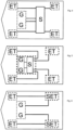
- the embodiment of the apparatus according to the invention shown in Fig. 4 and 5 comprises a single engine room in a redundancy zone and an energy storage subsystem local to each thruster wherein each thruster is in separate redundancy zones together with respective energy storage subsystem.
- any single redundancy zone can fail without loss of operational capability.
- a single failure will leave maximum one thruster unavailable, a clear improvement over prior art where one half of the ship can fail.
- This embodiment can take on further variations.
- Fig. 4 shows a system comprising a switchboard similar to that of prior art.
- a bus tie inside the switchboard is kept open and each switchboard subsystem is powered separately from the generator system.
- This has the advantage of operating flexibility between IMO class 3 mode and a non-IMO class 3 mode with lower running costs by operating fewer engines to drive the generators.
- the system also negates the requirement to have generators capable of double the power required for dynamic positioning operating associated with the baseline design in order to have sufficient power available following a single failure. Operating fewer engines at higher load has both fuel consumption and emissions benefits.
- Generators can be in a redundancy zone as shown in Fig. 4 or not in a separate redundancy zone as shown in Fig. 7
- Fig. 5 shows an embodiment with a switchboard co-located with the generators, where separate power cables from the single engine room feed each thruster redundancy zone. This has the advantage of simplicity.
- fire-proof sub-divisions are implemented according to the A60 standard.
- switchboard system is split into switchboard subsystems that are local to at least two thruster redundancy zones.
- Fig. 6 shows such an embodiment wherein the switchboard subsystems route power from the generator system to the redundancy zone local to the switchboard subsystem as well as to other thruster redundancy zones.
- Fig. 2 and 3 show a single cable from the single engine room and from the energy storage unit. Nevertheless one can also envisage a system where there instead are two cables from these, where a first cable from a first group of engines and a first cable from a first part of the energy storage system are connected to a first switchboard subsystem and a second cable from a second group of engines and a second cable from a second part of the energy storage system are connected to a second switchboard subsystem.
- a bus tie can be provided to selectively connect the first and second switchboard subsystems.
- redundancy zone having an energy storage unit and a thruster further comprising a sub division between the energy storage system and the thruster.
- Said sub division can be provided to avoid fumes mixing, or to provide extra barrier against fire or flooding.
- Such divided compartments still provide the same effect as a normal redundancy zone and thus still fall within the ambit of the invention.
- the invention according to the application finds use in high reliability vessel with improved capability in case of single and multiple point of failure.
Landscapes
- Engineering & Computer Science (AREA)
- Chemical & Material Sciences (AREA)
- Combustion & Propulsion (AREA)
- Mechanical Engineering (AREA)
- Ocean & Marine Engineering (AREA)
- Power Engineering (AREA)
- Architecture (AREA)
- Civil Engineering (AREA)
- Structural Engineering (AREA)
- Stand-By Power Supply Arrangements (AREA)
- Measurement Of Radiation (AREA)
- Analysing Materials By The Use Of Radiation (AREA)
Priority Applications (1)
| Application Number | Priority Date | Filing Date | Title |
|---|---|---|---|
| HRP20230619TT HRP20230619T1 (hr) | 2013-08-06 | 2014-08-05 | Plovilo za dinamičko pozicioniranje |
Applications Claiming Priority (3)
| Application Number | Priority Date | Filing Date | Title |
|---|---|---|---|
| NO20131066 | 2013-08-06 | ||
| GB1314173.4A GB2516940B (en) | 2013-08-07 | 2013-08-07 | A dynamic positioning vessel with a plurality of redundancy zones |
| PCT/NO2014/050137 WO2015020531A1 (en) | 2013-08-06 | 2014-08-05 | Dynamic positioning vessel |
Publications (3)
| Publication Number | Publication Date |
|---|---|
| EP3030484A1 EP3030484A1 (en) | 2016-06-15 |
| EP3030484A4 EP3030484A4 (en) | 2017-03-08 |
| EP3030484B1 true EP3030484B1 (en) | 2023-05-24 |
Family
ID=52461726
Family Applications (1)
| Application Number | Title | Priority Date | Filing Date |
|---|---|---|---|
| EP14834157.1A Active EP3030484B1 (en) | 2013-08-06 | 2014-08-05 | Dynamic positioning vessel |
Country Status (10)
| Country | Link |
|---|---|
| US (2) | US20160185434A1 (pl) |
| EP (1) | EP3030484B1 (pl) |
| KR (1) | KR102267468B1 (pl) |
| DK (1) | DK3030484T3 (pl) |
| ES (1) | ES2952407T3 (pl) |
| FI (1) | FI3030484T3 (pl) |
| HR (1) | HRP20230619T1 (pl) |
| PL (1) | PL3030484T3 (pl) |
| PT (1) | PT3030484T (pl) |
| WO (1) | WO2015020531A1 (pl) |
Families Citing this family (7)
| Publication number | Priority date | Publication date | Assignee | Title |
|---|---|---|---|---|
| US10322787B2 (en) | 2016-03-01 | 2019-06-18 | Brunswick Corporation | Marine vessel station keeping systems and methods |
| US10640190B1 (en) | 2016-03-01 | 2020-05-05 | Brunswick Corporation | System and method for controlling course of a marine vessel |
| US10671073B2 (en) * | 2017-02-15 | 2020-06-02 | Brunswick Corporation | Station keeping system and method |
| US11482753B2 (en) * | 2017-09-01 | 2022-10-25 | Maersk Drilling A/S | Fire-resistant energy storage devices and associated systems and methods |
| KR102016033B1 (ko) * | 2018-05-03 | 2019-08-29 | 한국조선해양 주식회사 | 동적 위치 제어 시스템 및 이를 구비하는 선박 |
| MY205131A (en) * | 2018-05-17 | 2024-10-03 | Ukalal Devjibhai Parmar | Submersible water lifting assembly and automatic fire fighting system for unmanned platforms having said system |
| CN114194347B (zh) * | 2022-01-05 | 2022-12-27 | 广东海洋大学 | 半潜式海洋平台的动力定位方法、装置、设备及介质 |
Citations (4)
| Publication number | Priority date | Publication date | Assignee | Title |
|---|---|---|---|---|
| EP2442417A1 (en) * | 2010-10-18 | 2012-04-18 | Siemens Aktiengesellschaft | A protection system for electrical power distribution system using directional current detection and logic within protective relays |
| WO2012175624A1 (en) * | 2011-06-22 | 2012-12-27 | Wärtsilä Finland Oy | Improvement in ship propulsion engine fuel efficiency |
| EP2709229A1 (en) * | 2012-09-17 | 2014-03-19 | GE Energy Power Conversion Technology Ltd | Power distribution systems |
| EP2916419A1 (en) * | 2014-03-04 | 2015-09-09 | Siemens Aktiengesellschaft | Power system of a floating vessel |
Family Cites Families (17)
| Publication number | Priority date | Publication date | Assignee | Title |
|---|---|---|---|---|
| US4281615A (en) * | 1977-10-31 | 1981-08-04 | Sedco, Inc. | Self-propelled semi-submersible service vessel |
| US6188139B1 (en) * | 1999-01-20 | 2001-02-13 | Electric Boat Corporation | Integrated marine power distribution arrangement |
| US6247421B1 (en) * | 1999-06-16 | 2001-06-19 | Gva Consultants Ab | Method for DP-conversion of an existing semi-submersible rig |
| DE20214297U1 (de) * | 2002-09-14 | 2004-02-12 | Siemens Ag | Marine-/Navy-Schiffstypen übergreifendes System |
| US6848382B1 (en) * | 2002-12-23 | 2005-02-01 | Joannes Raymond Mari Bekker | Portable dynamic positioning system with self-contained electric thrusters |
| DE10353967A1 (de) * | 2003-11-19 | 2005-07-07 | Siemens Ag | Energieerzeugungs-, Verteilungs- und Bordstromversorgungssystem für emissionsarme Überwasser-Marine(Navy)-Schiffe unterschiedlicher Klassen und Größen |
| NO330440B1 (no) | 2006-08-21 | 2011-04-11 | Frigstad Engineering Ltd | Anordning ved kabelrom i et borefartoy |
| GB2442770A (en) | 2006-10-13 | 2008-04-16 | Rolls Royce Plc | Mixed ship propulsion system |
| US7710081B2 (en) * | 2006-10-27 | 2010-05-04 | Direct Drive Systems, Inc. | Electromechanical energy conversion systems |
| WO2009052843A1 (en) | 2007-10-22 | 2009-04-30 | Siemens Aktiengesellschaft | Electrical switchgear, particularly for connecting generators and thrusters in dynamically positioned vessels |
| US8159082B2 (en) * | 2008-09-05 | 2012-04-17 | General Electric Company | Systems and methods for providing an uninterruptible power supply to a ship-service bus of a marine vessel |
| US7806065B1 (en) * | 2008-10-01 | 2010-10-05 | Thrustmaster of Texas, Inc. | Modular system for fast and easy conversion of anchor moored semi-submersibles to dynamically positioned semis without the need for dry docking, using a diesel electric thruster system |
| FR2966799B1 (fr) * | 2010-10-27 | 2012-12-21 | Converteam Technology Ltd | Navire avec un systeme redondant d'alimentation electrique commun au propulseur babord et au propulseur tribord |
| EP2451041A1 (en) * | 2010-11-03 | 2012-05-09 | Converteam Technology Ltd | Methods of operating dual fed systems |
| EP2482425A1 (en) | 2011-02-01 | 2012-08-01 | Siemens Aktiengesellschaft | Blackout ride-through system |
| ES2547154T3 (es) * | 2011-07-18 | 2015-10-01 | Abb As | Sistema de suministro de energía para buques |
| DK2654157T3 (da) | 2012-04-17 | 2022-09-12 | Siemens Energy AS | Fejlbeskyttelsessystem for et elektrisk system til et dynamisk positioneret fartøj |
-
2014
- 2014-08-05 HR HRP20230619TT patent/HRP20230619T1/hr unknown
- 2014-08-05 FI FIEP14834157.1T patent/FI3030484T3/fi active
- 2014-08-05 DK DK14834157.1T patent/DK3030484T3/da active
- 2014-08-05 WO PCT/NO2014/050137 patent/WO2015020531A1/en not_active Ceased
- 2014-08-05 US US14/910,677 patent/US20160185434A1/en not_active Abandoned
- 2014-08-05 ES ES14834157T patent/ES2952407T3/es active Active
- 2014-08-05 EP EP14834157.1A patent/EP3030484B1/en active Active
- 2014-08-05 KR KR1020167006058A patent/KR102267468B1/ko active Active
- 2014-08-05 PL PL14834157.1T patent/PL3030484T3/pl unknown
- 2014-08-05 PT PT148341571T patent/PT3030484T/pt unknown
-
2019
- 2019-06-12 US US16/439,697 patent/US10870474B2/en active Active
Patent Citations (4)
| Publication number | Priority date | Publication date | Assignee | Title |
|---|---|---|---|---|
| EP2442417A1 (en) * | 2010-10-18 | 2012-04-18 | Siemens Aktiengesellschaft | A protection system for electrical power distribution system using directional current detection and logic within protective relays |
| WO2012175624A1 (en) * | 2011-06-22 | 2012-12-27 | Wärtsilä Finland Oy | Improvement in ship propulsion engine fuel efficiency |
| EP2709229A1 (en) * | 2012-09-17 | 2014-03-19 | GE Energy Power Conversion Technology Ltd | Power distribution systems |
| EP2916419A1 (en) * | 2014-03-04 | 2015-09-09 | Siemens Aktiengesellschaft | Power system of a floating vessel |
Also Published As
| Publication number | Publication date |
|---|---|
| US20190291839A1 (en) | 2019-09-26 |
| US20160185434A1 (en) | 2016-06-30 |
| WO2015020531A1 (en) | 2015-02-12 |
| PL3030484T3 (pl) | 2023-09-18 |
| FI3030484T3 (fi) | 2023-07-27 |
| KR20160093590A (ko) | 2016-08-08 |
| DK3030484T3 (da) | 2023-07-31 |
| HRP20230619T1 (hr) | 2023-09-29 |
| US10870474B2 (en) | 2020-12-22 |
| KR102267468B1 (ko) | 2021-06-23 |
| EP3030484A4 (en) | 2017-03-08 |
| ES2952407T3 (es) | 2023-10-31 |
| EP3030484A1 (en) | 2016-06-15 |
| PT3030484T (pt) | 2023-08-17 |
Similar Documents
| Publication | Publication Date | Title |
|---|---|---|
| EP3030484B1 (en) | Dynamic positioning vessel | |
| US7544108B2 (en) | Power generation, distribution, and on-board power supply system for low-emissive surface marine (navy) ships of different classes and sizes | |
| US8159082B2 (en) | Systems and methods for providing an uninterruptible power supply to a ship-service bus of a marine vessel | |
| EP3209556B1 (en) | Power system of a floating vessel | |
| JP6676276B2 (ja) | 蓄電池推進システム及び蓄電池推進船 | |
| US10014707B2 (en) | Method for managing the electric power network of an aircraft | |
| CN111903028B (zh) | 冗余供电系统 | |
| US20230187930A1 (en) | Dc grid | |
| EP2916419A1 (en) | Power system of a floating vessel | |
| ES2426776T3 (es) | Sistema de propulsor redundante | |
| ES3032761T3 (en) | Power supply system for a water-bound device | |
| US20240113523A1 (en) | Energy storage system and power supply system for marine vessels | |
| EP3552948B1 (en) | Navigation method for ship, and ship | |
| CN217036824U (zh) | 一种推进器电源切换系统和动力定位船舶 | |
| GB2516940A (en) | Dynamic positioning vessel | |
| CN106019018B (zh) | 一种电压骤降穿越实船短路试验方法 | |
| CN113991829B (zh) | 一种推进器电源切换系统 | |
| Селезньов et al. | Application of modern innovation technologies of electrical engineering or ship power systems development | |
| KR20200049248A (ko) | 하이브리드 선박 | |
| Stavnesli | Adapting Alternate Energy Sources and Future Loads in DC Power Systems | |
| JP2024011134A (ja) | 船舶用電力システム、船舶、および、船舶用電力システムの使用方法 | |
| Doerry | Shipboard Distribution Systems: Present and Future | |
| WO2021175695A1 (en) | Vessel energy management system | |
| JP2020029204A (ja) | 船舶 |
Legal Events
| Date | Code | Title | Description |
|---|---|---|---|
| REG | Reference to a national code |
Ref country code: HR Ref legal event code: TUEP Ref document number: P20230619T Country of ref document: HR |
|
| PUAI | Public reference made under article 153(3) epc to a published international application that has entered the european phase |
Free format text: ORIGINAL CODE: 0009012 |
|
| 17P | Request for examination filed |
Effective date: 20160307 |
|
| AK | Designated contracting states |
Kind code of ref document: A1 Designated state(s): AL AT BE BG CH CY CZ DE DK EE ES FI FR GB GR HR HU IE IS IT LI LT LU LV MC MK MT NL NO PL PT RO RS SE SI SK SM TR |
|
| AX | Request for extension of the european patent |
Extension state: BA ME |
|
| RIN1 | Information on inventor provided before grant (corrected) |
Inventor name: HIRST, MIKE |
|
| DAX | Request for extension of the european patent (deleted) | ||
| A4 | Supplementary search report drawn up and despatched |
Effective date: 20170208 |
|
| RIC1 | Information provided on ipc code assigned before grant |
Ipc: H02B 1/015 20060101ALI20170202BHEP Ipc: B63H 25/42 20060101ALI20170202BHEP Ipc: B63H 21/17 20060101AFI20170202BHEP Ipc: B63H 23/24 20060101ALI20170202BHEP |
|
| STAA | Information on the status of an ep patent application or granted ep patent |
Free format text: STATUS: EXAMINATION IS IN PROGRESS |
|
| 17Q | First examination report despatched |
Effective date: 20180227 |
|
| RAP1 | Party data changed (applicant data changed or rights of an application transferred) |
Owner name: KONGSBERG MARITIME CM AS |
|
| RAP1 | Party data changed (applicant data changed or rights of an application transferred) |
Owner name: KONGSBERG MARITIME AS |
|
| GRAP | Despatch of communication of intention to grant a patent |
Free format text: ORIGINAL CODE: EPIDOSNIGR1 |
|
| STAA | Information on the status of an ep patent application or granted ep patent |
Free format text: STATUS: GRANT OF PATENT IS INTENDED |
|
| INTG | Intention to grant announced |
Effective date: 20221207 |
|
| GRAS | Grant fee paid |
Free format text: ORIGINAL CODE: EPIDOSNIGR3 |
|
| GRAA | (expected) grant |
Free format text: ORIGINAL CODE: 0009210 |
|
| STAA | Information on the status of an ep patent application or granted ep patent |
Free format text: STATUS: THE PATENT HAS BEEN GRANTED |
|
| AK | Designated contracting states |
Kind code of ref document: B1 Designated state(s): AL AT BE BG CH CY CZ DE DK EE ES FI FR GB GR HR HU IE IS IT LI LT LU LV MC MK MT NL NO PL PT RO RS SE SI SK SM TR |
|
| REG | Reference to a national code |
Ref country code: GB Ref legal event code: FG4D |
|
| REG | Reference to a national code |
Ref country code: CH Ref legal event code: EP |
|
| REG | Reference to a national code |
Ref country code: DE Ref legal event code: R096 Ref document number: 602014087032 Country of ref document: DE |
|
| P01 | Opt-out of the competence of the unified patent court (upc) registered |
Effective date: 20230307 |
|
| REG | Reference to a national code |
Ref country code: AT Ref legal event code: REF Ref document number: 1569360 Country of ref document: AT Kind code of ref document: T Effective date: 20230615 |
|
| REG | Reference to a national code |
Ref country code: IE Ref legal event code: FG4D |
|
| REG | Reference to a national code |
Ref country code: FI Ref legal event code: FGE |
|
| REG | Reference to a national code |
Ref country code: DK Ref legal event code: T3 Effective date: 20230724 |
|
| REG | Reference to a national code |
Ref country code: RO Ref legal event code: EPE |
|
| REG | Reference to a national code |
Ref country code: SE Ref legal event code: TRGR |
|
| REG | Reference to a national code |
Ref country code: NL Ref legal event code: FP |
|
| REG | Reference to a national code |
Ref country code: PT Ref legal event code: SC4A Ref document number: 3030484 Country of ref document: PT Date of ref document: 20230817 Kind code of ref document: T Free format text: AVAILABILITY OF NATIONAL TRANSLATION Effective date: 20230802 |
|
| REG | Reference to a national code |
Ref country code: LT Ref legal event code: MG9D |
|
| REG | Reference to a national code |
Ref country code: HR Ref legal event code: ODRP Ref document number: P20230619T Country of ref document: HR Payment date: 20230628 Year of fee payment: 10 |
|
| REG | Reference to a national code |
Ref country code: HR Ref legal event code: T1PR Ref document number: P20230619 Country of ref document: HR |
|
| REG | Reference to a national code |
Ref country code: NO Ref legal event code: T2 Effective date: 20230524 |
|
| REG | Reference to a national code |
Ref country code: AT Ref legal event code: MK05 Ref document number: 1569360 Country of ref document: AT Kind code of ref document: T Effective date: 20230524 |
|
| PG25 | Lapsed in a contracting state [announced via postgrant information from national office to epo] |
Ref country code: AT Free format text: LAPSE BECAUSE OF FAILURE TO SUBMIT A TRANSLATION OF THE DESCRIPTION OR TO PAY THE FEE WITHIN THE PRESCRIBED TIME-LIMIT Effective date: 20230524 |
|
| REG | Reference to a national code |
Ref country code: ES Ref legal event code: FG2A Ref document number: 2952407 Country of ref document: ES Kind code of ref document: T3 Effective date: 20231031 |
|
| REG | Reference to a national code |
Ref country code: GR Ref legal event code: EP Ref document number: 20230401187 Country of ref document: GR Effective date: 20231010 |
|
| PG25 | Lapsed in a contracting state [announced via postgrant information from national office to epo] |
Ref country code: RS Free format text: LAPSE BECAUSE OF FAILURE TO SUBMIT A TRANSLATION OF THE DESCRIPTION OR TO PAY THE FEE WITHIN THE PRESCRIBED TIME-LIMIT Effective date: 20230524 Ref country code: LV Free format text: LAPSE BECAUSE OF FAILURE TO SUBMIT A TRANSLATION OF THE DESCRIPTION OR TO PAY THE FEE WITHIN THE PRESCRIBED TIME-LIMIT Effective date: 20230524 Ref country code: LT Free format text: LAPSE BECAUSE OF FAILURE TO SUBMIT A TRANSLATION OF THE DESCRIPTION OR TO PAY THE FEE WITHIN THE PRESCRIBED TIME-LIMIT Effective date: 20230524 Ref country code: IS Free format text: LAPSE BECAUSE OF FAILURE TO SUBMIT A TRANSLATION OF THE DESCRIPTION OR TO PAY THE FEE WITHIN THE PRESCRIBED TIME-LIMIT Effective date: 20230924 |
|
| PG25 | Lapsed in a contracting state [announced via postgrant information from national office to epo] |
Ref country code: SK Free format text: LAPSE BECAUSE OF FAILURE TO SUBMIT A TRANSLATION OF THE DESCRIPTION OR TO PAY THE FEE WITHIN THE PRESCRIBED TIME-LIMIT Effective date: 20230524 |
|
| PG25 | Lapsed in a contracting state [announced via postgrant information from national office to epo] |
Ref country code: SM Free format text: LAPSE BECAUSE OF FAILURE TO SUBMIT A TRANSLATION OF THE DESCRIPTION OR TO PAY THE FEE WITHIN THE PRESCRIBED TIME-LIMIT Effective date: 20230524 Ref country code: SK Free format text: LAPSE BECAUSE OF FAILURE TO SUBMIT A TRANSLATION OF THE DESCRIPTION OR TO PAY THE FEE WITHIN THE PRESCRIBED TIME-LIMIT Effective date: 20230524 Ref country code: EE Free format text: LAPSE BECAUSE OF FAILURE TO SUBMIT A TRANSLATION OF THE DESCRIPTION OR TO PAY THE FEE WITHIN THE PRESCRIBED TIME-LIMIT Effective date: 20230524 Ref country code: CZ Free format text: LAPSE BECAUSE OF FAILURE TO SUBMIT A TRANSLATION OF THE DESCRIPTION OR TO PAY THE FEE WITHIN THE PRESCRIBED TIME-LIMIT Effective date: 20230524 |
|
| REG | Reference to a national code |
Ref country code: DE Ref legal event code: R097 Ref document number: 602014087032 Country of ref document: DE |
|
| PG25 | Lapsed in a contracting state [announced via postgrant information from national office to epo] |
Ref country code: MC Free format text: LAPSE BECAUSE OF FAILURE TO SUBMIT A TRANSLATION OF THE DESCRIPTION OR TO PAY THE FEE WITHIN THE PRESCRIBED TIME-LIMIT Effective date: 20230524 |
|
| PG25 | Lapsed in a contracting state [announced via postgrant information from national office to epo] |
Ref country code: MC Free format text: LAPSE BECAUSE OF FAILURE TO SUBMIT A TRANSLATION OF THE DESCRIPTION OR TO PAY THE FEE WITHIN THE PRESCRIBED TIME-LIMIT Effective date: 20230524 |
|
| PLBE | No opposition filed within time limit |
Free format text: ORIGINAL CODE: 0009261 |
|
| STAA | Information on the status of an ep patent application or granted ep patent |
Free format text: STATUS: NO OPPOSITION FILED WITHIN TIME LIMIT |
|
| PG25 | Lapsed in a contracting state [announced via postgrant information from national office to epo] |
Ref country code: LU Free format text: LAPSE BECAUSE OF NON-PAYMENT OF DUE FEES Effective date: 20230805 |
|
| PG25 | Lapsed in a contracting state [announced via postgrant information from national office to epo] |
Ref country code: LU Free format text: LAPSE BECAUSE OF NON-PAYMENT OF DUE FEES Effective date: 20230805 |
|
| 26N | No opposition filed |
Effective date: 20240227 |
|
| PG25 | Lapsed in a contracting state [announced via postgrant information from national office to epo] |
Ref country code: SI Free format text: LAPSE BECAUSE OF FAILURE TO SUBMIT A TRANSLATION OF THE DESCRIPTION OR TO PAY THE FEE WITHIN THE PRESCRIBED TIME-LIMIT Effective date: 20230524 |
|
| REG | Reference to a national code |
Ref country code: BE Ref legal event code: MM Effective date: 20230831 |
|
| REG | Reference to a national code |
Ref country code: IE Ref legal event code: MM4A |
|
| PG25 | Lapsed in a contracting state [announced via postgrant information from national office to epo] |
Ref country code: SI Free format text: LAPSE BECAUSE OF FAILURE TO SUBMIT A TRANSLATION OF THE DESCRIPTION OR TO PAY THE FEE WITHIN THE PRESCRIBED TIME-LIMIT Effective date: 20230524 |
|
| PG25 | Lapsed in a contracting state [announced via postgrant information from national office to epo] |
Ref country code: IE Free format text: LAPSE BECAUSE OF NON-PAYMENT OF DUE FEES Effective date: 20230805 |
|
| PG25 | Lapsed in a contracting state [announced via postgrant information from national office to epo] |
Ref country code: IE Free format text: LAPSE BECAUSE OF NON-PAYMENT OF DUE FEES Effective date: 20230805 |
|
| REG | Reference to a national code |
Ref country code: HR Ref legal event code: ODRP Ref document number: P20230619 Country of ref document: HR Payment date: 20240718 Year of fee payment: 11 |
|
| PG25 | Lapsed in a contracting state [announced via postgrant information from national office to epo] |
Ref country code: BE Free format text: LAPSE BECAUSE OF NON-PAYMENT OF DUE FEES Effective date: 20230831 |
|
| PG25 | Lapsed in a contracting state [announced via postgrant information from national office to epo] |
Ref country code: BG Free format text: LAPSE BECAUSE OF FAILURE TO SUBMIT A TRANSLATION OF THE DESCRIPTION OR TO PAY THE FEE WITHIN THE PRESCRIBED TIME-LIMIT Effective date: 20230524 |
|
| PG25 | Lapsed in a contracting state [announced via postgrant information from national office to epo] |
Ref country code: BG Free format text: LAPSE BECAUSE OF FAILURE TO SUBMIT A TRANSLATION OF THE DESCRIPTION OR TO PAY THE FEE WITHIN THE PRESCRIBED TIME-LIMIT Effective date: 20230524 |
|
| PG25 | Lapsed in a contracting state [announced via postgrant information from national office to epo] |
Ref country code: CY Free format text: LAPSE BECAUSE OF FAILURE TO SUBMIT A TRANSLATION OF THE DESCRIPTION OR TO PAY THE FEE WITHIN THE PRESCRIBED TIME-LIMIT; INVALID AB INITIO Effective date: 20140805 |
|
| PG25 | Lapsed in a contracting state [announced via postgrant information from national office to epo] |
Ref country code: HU Free format text: LAPSE BECAUSE OF FAILURE TO SUBMIT A TRANSLATION OF THE DESCRIPTION OR TO PAY THE FEE WITHIN THE PRESCRIBED TIME-LIMIT; INVALID AB INITIO Effective date: 20140805 |
|
| REG | Reference to a national code |
Ref country code: HR Ref legal event code: ODRP Ref document number: P20230619 Country of ref document: HR Payment date: 20250731 Year of fee payment: 12 |
|
| PGFP | Annual fee paid to national office [announced via postgrant information from national office to epo] |
Ref country code: NL Payment date: 20250826 Year of fee payment: 12 |
|
| PGFP | Annual fee paid to national office [announced via postgrant information from national office to epo] |
Ref country code: ES Payment date: 20250901 Year of fee payment: 12 Ref country code: PT Payment date: 20250722 Year of fee payment: 12 Ref country code: FI Payment date: 20250825 Year of fee payment: 12 |
|
| PGFP | Annual fee paid to national office [announced via postgrant information from national office to epo] |
Ref country code: DK Payment date: 20250825 Year of fee payment: 12 Ref country code: DE Payment date: 20250827 Year of fee payment: 12 |
|
| PGFP | Annual fee paid to national office [announced via postgrant information from national office to epo] |
Ref country code: GR Payment date: 20250826 Year of fee payment: 12 Ref country code: NO Payment date: 20250827 Year of fee payment: 12 |
|
| PGFP | Annual fee paid to national office [announced via postgrant information from national office to epo] |
Ref country code: TR Payment date: 20250721 Year of fee payment: 12 Ref country code: PL Payment date: 20250724 Year of fee payment: 12 Ref country code: IT Payment date: 20250820 Year of fee payment: 12 |
|
| PGFP | Annual fee paid to national office [announced via postgrant information from national office to epo] |
Ref country code: GB Payment date: 20250827 Year of fee payment: 12 |
|
| PGFP | Annual fee paid to national office [announced via postgrant information from national office to epo] |
Ref country code: HR Payment date: 20250731 Year of fee payment: 12 |
|
| PGFP | Annual fee paid to national office [announced via postgrant information from national office to epo] |
Ref country code: FR Payment date: 20250825 Year of fee payment: 12 |
|
| PGFP | Annual fee paid to national office [announced via postgrant information from national office to epo] |
Ref country code: SE Payment date: 20250827 Year of fee payment: 12 Ref country code: CH Payment date: 20250901 Year of fee payment: 12 |
|
| PGFP | Annual fee paid to national office [announced via postgrant information from national office to epo] |
Ref country code: RO Payment date: 20250725 Year of fee payment: 12 |