EP3030352B1 - Cartridge for dispensing a fluid, automatic analyser and method of analysing a biological sample - Google Patents
Cartridge for dispensing a fluid, automatic analyser and method of analysing a biological sample Download PDFInfo
- Publication number
- EP3030352B1 EP3030352B1 EP14742198.6A EP14742198A EP3030352B1 EP 3030352 B1 EP3030352 B1 EP 3030352B1 EP 14742198 A EP14742198 A EP 14742198A EP 3030352 B1 EP3030352 B1 EP 3030352B1
- Authority
- EP
- European Patent Office
- Prior art keywords
- cartridge
- fluid
- reservoir chamber
- dispensing
- pumping element
- Prior art date
- Legal status (The legal status is an assumption and is not a legal conclusion. Google has not performed a legal analysis and makes no representation as to the accuracy of the status listed.)
- Active
Links
Images


Classifications
-
- G—PHYSICS
- G01—MEASURING; TESTING
- G01N—INVESTIGATING OR ANALYSING MATERIALS BY DETERMINING THEIR CHEMICAL OR PHYSICAL PROPERTIES
- G01N35/00—Automatic analysis not limited to methods or materials provided for in any single one of groups G01N1/00 - G01N33/00; Handling materials therefor
- G01N35/10—Devices for transferring samples or any liquids to, in, or from, the analysis apparatus, e.g. suction devices, injection devices
- G01N35/1002—Reagent dispensers
-
- B—PERFORMING OPERATIONS; TRANSPORTING
- B01—PHYSICAL OR CHEMICAL PROCESSES OR APPARATUS IN GENERAL
- B01L—CHEMICAL OR PHYSICAL LABORATORY APPARATUS FOR GENERAL USE
- B01L3/00—Containers or dishes for laboratory use, e.g. laboratory glassware; Droppers
- B01L3/02—Burettes; Pipettes
- B01L3/0241—Drop counters; Drop formers
- B01L3/0268—Drop counters; Drop formers using pulse dispensing or spraying, eg. inkjet type, piezo actuated ejection of droplets from capillaries
-
- B—PERFORMING OPERATIONS; TRANSPORTING
- B01—PHYSICAL OR CHEMICAL PROCESSES OR APPARATUS IN GENERAL
- B01L—CHEMICAL OR PHYSICAL LABORATORY APPARATUS FOR GENERAL USE
- B01L3/00—Containers or dishes for laboratory use, e.g. laboratory glassware; Droppers
- B01L3/02—Burettes; Pipettes
- B01L3/0286—Ergonomic aspects, e.g. form or arrangement of controls
-
- G—PHYSICS
- G01—MEASURING; TESTING
- G01N—INVESTIGATING OR ANALYSING MATERIALS BY DETERMINING THEIR CHEMICAL OR PHYSICAL PROPERTIES
- G01N35/00—Automatic analysis not limited to methods or materials provided for in any single one of groups G01N1/00 - G01N33/00; Handling materials therefor
- G01N35/10—Devices for transferring samples or any liquids to, in, or from, the analysis apparatus, e.g. suction devices, injection devices
- G01N35/1009—Characterised by arrangements for controlling the aspiration or dispense of liquids
-
- B—PERFORMING OPERATIONS; TRANSPORTING
- B01—PHYSICAL OR CHEMICAL PROCESSES OR APPARATUS IN GENERAL
- B01L—CHEMICAL OR PHYSICAL LABORATORY APPARATUS FOR GENERAL USE
- B01L2200/00—Solutions for specific problems relating to chemical or physical laboratory apparatus
- B01L2200/04—Exchange or ejection of cartridges, containers or reservoirs
-
- B—PERFORMING OPERATIONS; TRANSPORTING
- B01—PHYSICAL OR CHEMICAL PROCESSES OR APPARATUS IN GENERAL
- B01L—CHEMICAL OR PHYSICAL LABORATORY APPARATUS FOR GENERAL USE
- B01L2200/00—Solutions for specific problems relating to chemical or physical laboratory apparatus
- B01L2200/06—Fluid handling related problems
- B01L2200/0684—Venting, avoiding backpressure, avoid gas bubbles
-
- B—PERFORMING OPERATIONS; TRANSPORTING
- B01—PHYSICAL OR CHEMICAL PROCESSES OR APPARATUS IN GENERAL
- B01L—CHEMICAL OR PHYSICAL LABORATORY APPARATUS FOR GENERAL USE
- B01L2300/00—Additional constructional details
- B01L2300/06—Auxiliary integrated devices, integrated components
- B01L2300/0609—Holders integrated in container to position an object
-
- B—PERFORMING OPERATIONS; TRANSPORTING
- B01—PHYSICAL OR CHEMICAL PROCESSES OR APPARATUS IN GENERAL
- B01L—CHEMICAL OR PHYSICAL LABORATORY APPARATUS FOR GENERAL USE
- B01L2300/00—Additional constructional details
- B01L2300/08—Geometry, shape and general structure
- B01L2300/0832—Geometry, shape and general structure cylindrical, tube shaped
-
- B—PERFORMING OPERATIONS; TRANSPORTING
- B01—PHYSICAL OR CHEMICAL PROCESSES OR APPARATUS IN GENERAL
- B01L—CHEMICAL OR PHYSICAL LABORATORY APPARATUS FOR GENERAL USE
- B01L2300/00—Additional constructional details
- B01L2300/12—Specific details about materials
- B01L2300/123—Flexible; Elastomeric
-
- B—PERFORMING OPERATIONS; TRANSPORTING
- B01—PHYSICAL OR CHEMICAL PROCESSES OR APPARATUS IN GENERAL
- B01L—CHEMICAL OR PHYSICAL LABORATORY APPARATUS FOR GENERAL USE
- B01L2400/00—Moving or stopping fluids
- B01L2400/04—Moving fluids with specific forces or mechanical means
- B01L2400/0475—Moving fluids with specific forces or mechanical means specific mechanical means and fluid pressure
- B01L2400/0481—Moving fluids with specific forces or mechanical means specific mechanical means and fluid pressure squeezing of channels or chambers
-
- B—PERFORMING OPERATIONS; TRANSPORTING
- B01—PHYSICAL OR CHEMICAL PROCESSES OR APPARATUS IN GENERAL
- B01L—CHEMICAL OR PHYSICAL LABORATORY APPARATUS FOR GENERAL USE
- B01L2400/00—Moving or stopping fluids
- B01L2400/08—Regulating or influencing the flow resistance
- B01L2400/082—Active control of flow resistance, e.g. flow controllers
Definitions
- the present invention relates to the field of fluidics, in particular cartridges for dispensing microfluidic portions of fluids for the purpose of performing an analysis of a biological sample.
- EP 1 959 257 A2 discloses an automatic analyzer including a reagent cassette holding mechanism for holding a plurality of reagent cassettes.
- EP 1 959 257 A2 discloses that the analyzer has a reagent pipettor. The reagent pipettor is used for dispensing a reagent into a vessel containing a sample to initiate a chemical reaction.
- WO 2007/122387 discloses a cartridge for dispensing a reagent contained in a reagent reservoir.
- the cartridge comprises a reservoir which defines an enclosed gas space above the reagent.
- the cartridge further includes a gas vent that admits, in use, gas to the gas space.
- US 8318109 shows a microfluidic device for fluid manipulation and analyzing fluid samples.
- a bellows pump is fluidly connected to a microfluidic channel with a liquid barrier interposed between the bellows pump and an end of the microfluidic channel wherein the liquid barrier is gas permeable and liquid impermeable.
- US Patent 5,947,167 discloses a dispensing assembly with interchangeable cartridge pumps. Other fluid dispensers are disclosed in WO 2005/016534 A1 and WO 2007/122387 A2 .
- W. Streule et al., "PipeJet: A simple disposable dispenser for the nano- and microliter range", JALA, October 2004, pages 300-306 discloses a polymer tube clamped between two jaws. The backend of the tube is connected to a reservoir and serves as a supply channel.
- the invention provides for a cartridge for dispensing a fluid, an automatic analyzer for analyzing a biological sample and a method of analyzing a biological sample for detecting an analyte as claimed in the independent claims.
- Embodiments of the invention are given in the dependent claims.
- Embodiments of the invention are particularly advantageous for storing and dispensing a fluid being a suspension containing particles that sediment on a bottom portion of the cartridge.
- a fluid flow Prior to dispensing a portion of the fluid for the purpose of performing an analysis the sedimented particles or at least a portion of the sedimented particles are suspended by a fluid flow that is directed towards the sedimented particles and mixes the particles with the fluid so that the particles are put back into suspensed state.
- the sedimented particles are resuspended by the fluid flow that is caused by discharging a mixing volume from the end of the conduit when the compressible fluid pump is compressed.
- Embodiments of the invention are particularly advantageous as no rotating parts are required for mixing the sedimented particles with the fluid for re-suspending the sedimented particles within the fluid.
- This is accomplished by providing a single compressible fluid pump with a single elastic pumping element and an attached conduit extending from the fluid pump towards the fluid outlet which is particularly beneficial for microfluidic applications.
- the elastic pumping element Upon applying pressure onto the elastic pumping element the elastic pumping element is compressed, thereby compressing a pumping volume within the pumping element.
- the pressure on the pumping volume causes the pumping volume to move towards the conduit which ultimately leads to a flow of fluid from the conduit.
- the pumping element does not necessarily have to be made of elastic (that is reversibly deformable) material to be “elastic” as a whole.
- the pumping element may also be elastic because of its shape, for example if it is formed by bellows.
- An example for a pumping element being elastic because of its material would be an elastic membrane.
- the reservoir chamber of the cartridge has a bottom portion forming a sink, the sink comprising the fluid outlet of the reservoir chamber and the conduit extending into the sink until a predetermined distance from the fluid outlet.
- the cartridge has a baffle means forming a ventilation channel.
- the ventilation channel has a ventilation volume equal to or larger than the mixing volume that is dispensed by the fluid pump when the fluid pump is maximally compressed and therefore a maximum pumping volume is displaced by this compression. This has the advantage of minimizing the influx of ambient gases like oxygen or carbon dioxide from the surrounding atmosphere into the cartridge in order to limit degradation (e.g. by oxygenation) of the fluid contained in the reservoir chamber.
- a “cartridge” as understood herein comprises a receptacle for storing and dispensing a fluid.
- the cartridge has a mechanical interface that matches the mechanical interface of a holder of an automatic analyzer.
- the mechanical interfaces of the cartridge and the automatic analyzer enable mounting and release of the cartridge to and from the holder such that the cartridge can be conveniently replaced by a new cartridge when the cartridge is empty.
- the cartridge comprises a reservoir chamber for receiving and holding the fluid and the reservoir chamber is also operable for receiving a ventilation gas.
- the reservoir chamber comprises an inlet for receiving the ventilation gas. At least a portion of the reservoir chamber is operable for being filled with the ventilation gas when the cartridge is placed in an operating position.
- the inlet is located in the portion operable for being filled with the ventilation gas.
- the fluid comprises a reagent.
- the cartridge further comprises a baffle means for restricting gas diffusion through the inlet.
- the reservoir chamber receives the ventilation gas via the baffle means. Since the ventilation gas is provided directly to the gas within the reservoir, there is no formation of bubbles within the fluid fraction comprised within the reservoir chamber which otherwise could cause variations of the pressure within the reservoir chamber.
- the baffle means provides the ventilation gas directly to the portion of the reservoir chamber operable for being filled with the ventilation gas.
- Embodiments of the invention may therefore have the advantage that there is always an equilibrium in pressure between outside of the cartridge and in the gas within the reservoir chamber.
- Embodiments of the invention may also have the advantage that the baffle means reduce the diffusion of gases into the reservoir chamber which may damage or degrade the fluid (e.g. if the reservoir chamber contains oxygen-sensitive reagents which may degrade by contact with the ambient air).
- the baffle means may also reduce evaporation of the fluid within the reservoir chamber because the diffusion of gas or vapor out of the reservoir chamber is also reduced.
- a "controller” as used herein encompasses a device, machine, or apparatus for controlling the operation and/or function of one or more other devices. Examples of a controller may include, but are not limited to: a computer, a processor, an imbedded system or controller, a programmable logic controller, and a microcontroller.
- a 'computing device' or 'computer' as used herein encompasses to any device comprising a processor.
- a 'processor' as used herein encompasses an electronic component which is able to execute a program or machine executable instruction.
- a 'hardware interface' as used herein encompasses a interface which enables a processor or other controller to interact with and/or control an external computing device and/or apparatus.
- a hardware interface may allow a processor to send control signals or instructions to an external computing device and/or apparatus.
- the invention provides for a cartridge for dispensing a fluid.
- the cartridge comprises a reservoir chamber operable for receiving a fluid and for receiving a ventilation gas.
- a ventilation gas as used herein encompasses a gas which is used to equalize the pressure outside of the reservoir chamber and inside the reservoir chamber when fluid is removed from the reservoir chamber.
- the reservoir chamber comprises an inlet for receiving the ventilation gas and an outlet for dispensing the fluid. At least a portion of the reservoir chamber is operable for being filled with the ventilation gas when in an operating position.
- the inlet is located in the portion operable for being filled with the ventilation gas.
- ventilation gas is added to the reservoir chamber at a location where there is already ventilation gas or which is immediately filled with the ventilation gas.
- the fluid comprises a reagent.
- a reagent as used herein is a substance or compound that is added to a (bio-)chemical system in order to initiate or facilitate a chemical or biochemical reaction or to identify or monitor if such a reaction occurs.
- the cartridge further comprises a baffle means for restricting gas diffusion through the inlet.
- the reservoir chamber is operable for receiving the ventilation gas via the baffle means.
- a baffle means as used herein encompasses a structure which causes gas to follow a particular path in order to reach the inlet.
- the baffle means provides a means of restricting the diffusion of gas in and/or out of the inlet.
- the gas diffusion as used herein may refer to the diffusion of ventilation gas into the cartridge and/or gas already present in the reservoir chamber from diffusing out. This embodiment may be advantageous because it may preserve the lifetime of the reagent within the cartridge.
- the ventilation gas may cause the reagent to lose effectiveness or to lose its chemical reactivity; also gas inside the reservoir chamber may contain vapors from the fluid.
- the baffle means restricts the diffusion of the fluid vapor out of the inlet also. This may help to prevent the concentration of a particular reagent from changing.
- the cartridge comprises a closing element like a cap.
- the closing element may be operable for being moved into an open position for opening the inlet and/or for enabling access to the pump.
- the closing element may seal the inlet directly, that is the sealing effect of the closing element is at the inlet.
- the closing element seals the baffle or a portion of the baffle. This indirectly seals the inlet.
- a closing element as used herein may in some embodiments be a mechanical part operable to open or close the inlet.
- closing elements may include, a removable piece of plastic, a piece of tape, and a mechanical part which is operable to interlock with the cartridge such as a screw cap. Also clamping elements which can close flexible parts of the baffle can be used as closing elements.
- the inlet is operable for maintaining a constant pressure within the portion of the reservoir chamber that is operable for being filled with the ventilation gas. This embodiment may be beneficial, because maintaining the pressure at a constant value enables more accurate dispensing of the fluid. In some embodiments the inlet is operable for maintaining a constant pressure within the portion of the reservoir chamber that is operable for being filled with the ventilation gas when dispensing fluid.
- the ventilation gas may be normal atmospheric air.
- the baffle means is open to the atmosphere.
- the closing element is operable for being moved to an open position to open the inlet.
- the closing element may be removable or may be movable but fixed to the cartridge.
- the cartridge further comprises the fluid. i.e. is in a filled state.
- the fluid comprises a dispersion or suspension.
- a dispersion or suspension as used herein encompasses particles or particulates suspended within the fluid.
- the fluid may comprise latex particles.
- the fluid may comprise nanoparticles.
- the fluid may comprise magnetic particles.
- the cartridge further comprises a dispenser for dispensing the fluid.
- the dispenser is operable for receiving the fluid from the outlet of the reservoir chamber.
- the dispenser may be a microfluidic dispenser for dispensing a microfluidic portion of the fluid.
- the dispenser may comprise a nozzle.
- the dispenser may comprise a straight tube or may comprise a nozzle with one or more valves contained within it.
- the dispenser is operable to dispense fluid at a rate independent of the baffle means. In other words the dispensing of the fluid is not regulated or controlled by the baffle means.
- a regulator element restricts the flow of gas into the apparatus and effectively controls the release rate of a fluid.
- fluid can be dispensed at a rate that is effectively independent of the baffle means.
- the baffle means according to some embodiments of the invention may have such a small effect on the rate of dispensing that the effect is much smaller than the actual volume dispensed. This may enable more accurate dispensing of the fluid.
- the dispenser is a micro-fluidic dispensing assembly.
- the dispenser is operable for dispensing any one of the following: volumes less than 10 ⁇ L, less than 500 nL, less than 200 nL, less than 100 nL, and less than 20 nL.
- the invention provides for an automatic analyzer comprising the cartridge and comprising a holder for holding or receiving a cartridge according to an embodiment of the invention.
- the automatic analyzer comprises an actuator assembly operable for actuating the dispenser.
- the automatic analyzer also comprises an actuator assembly operable for actuating the fluid pump.
- the automatic analyzer further comprises a controller for controlling the operation of the actuator assembly and the fluid pump.
- the dispenser and the fluid pump may be mechanically, pneumatically, magnetically, and/or electrically actuated. This is dependent upon the implementation and how the dispenser is constructed.
- the cartridge is in an operating position when installed into the automatic analyzer.
- Fig. 1 illustrates a cartridge 100 according to an embodiment of the invention.
- the cartridge 100 comprises a reservoir chamber 102 for holding a fluid 104.
- the reservoir chamber 102 is only partially filled with the fluid 104.
- baffle means 108 Adjacent to the reservoir chamber 102 is a baffle means 108.
- the baffle means 108 in this example has a vent-to-atmosphere 110. Traveling through the baffle means there is an optional gas filter 112 which covers an inlet 114 to the reservoir chamber 102.
- the inlet 114 provides ventilation gas to the gas filled portion 106 of the reservoir chamber 102.
- the inlet 114 is attached to the baffle means 108.
- the fluid 104 exits the reservoir chamber 102 via an outlet 116.
- a dispenser 118 may comprise a nozzle or tube for dispensing the fluid when it is actuated by an external device, such as by an actuator assembly of an analyzer (cf. the embodiment of Fig. 5 ).
- the dispenser 118 serves for dispensing a dispensing volume 101 into a receptacle 103.
- the dispensing volume 101 of a reagent fluid contained within the reservoir chamber is mixed with a biological sample 105 contained in the receptacle 103 for performing an analysis for detecting an analyte.
- the dispenser 118 is connected to the fluid outlet 116 of the reservoir chamber 102.
- the cartridge 100 has a fluid pump 107 that comprises bellows 109 forming an elastic pumping element outside the housing of the cartridge 100.
- the bellows 109 are connected to a conduit 111 that extends from the bellows towards the fluid outlet 116.
- the fluid 104 is a suspension containing particles.
- the bellows 109 are compressed such as by an actuator of an analyzer that holds the cartridge 100 (cf. the embodiment of Fig. 5 ) (or in an alternative element also manually), such that a mixing volume 124 of fluid is discharged from the end portion 115 of the conduit 111 that causes a fluid flow mixing the sedimented particles 113 with the fluid 104, thus re-suspending the particles 113.
- the conduit 111 is tube- or pipette-shaped as shown in Fig. 1 .
- the conduit 111 may have a curved form.
- the bellows 109 may be arranged on a side of the housing of the cartridge 100 rather than on the top. In this instance the geometry of the cartridge 100 may require the conduit 111 to have a curved form.
- the reservoir chamber 102 has a bottom portion that forms the sink 117 which comprises the fluid outlet 116.
- the conduit 111 extends into the sink 117 until a predetermined distance d from the fluid outlet 116.
- the distance d may be in the range of 1 mm to 10 mm, preferably 3 mm.
- This has the advantage that the fluid flow that is caused by discharging the mixing volume from the end portion 115 of the conduit 111 is concentrated within the sink 117 for re-suspending the sedimented particles 113 that have sedimented on the bottom of the sink 117. This causes an intense mixing and re-suspending of the particles in this portion of the reservoir chamber.
- a portion of the fluid 104 that is in the sink 117 is dispensed as dispensing volume 101 by the dispenser 118.
- the reservoir chamber 102 and the pump that is constituted by the bellows 109 and the conduit 111 is a single form piece, such as an injection molded piece, that is produced such as by two component injection molding.
- the reservoir chamber 102 may consist of polypropylene and the pump, i.e. the bellows and the conduit 111, may consist of polyethylene.
- the bellows may be a single form piece with the cover of the cartridge.
- the particles 113 contained in the fluid 104 may comprise magnetic beads such as streptavidine-coated magnetic beads that are required for performing an electrochemiluminescence analysis. In alternative embodiments (e.g. for clinical chemistry tests), also coated latex particles can be used as particles 113.
- the fluid 104 may be any particle enhanced immunoassay reagent comprising suspended particles that may sediment after some storage time.
- the volume of air contained in the baffle means 108 is equal or larger than the maximum mixing volume 124 that is discharged when the bellows 109 are maximally compressed. This is to avoid or reduce the influx of air from the surrounding atmosphere into the reservoir chamber 102 when a pumping cycle is executed.
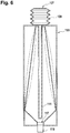
- the walls of the reservoir chamber can be flexible. These walls expand when the fluid pump is compressed (and the additional mixing volume is pressed into the reservoir chamber) and shrink when the fluid pump is decompressed and when fluid 104 is dispensed so that no baffle means is required.
- Such an embodiment without a baffle means is shown in Fig. 6 .
- the dashed lines show the variation of the volume of the reservoir chamber 102 during a pumping cycle.
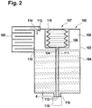
- Fig. 2 shows an alternative embodiment where the bellows 109 are integrated within the housing of the cartridge 100.
- the housing of the cartridge 100 may have a top portion with an opening 119 through which the bellows 109 is accessible for compression.
- an actuator of an automatic analyzer can be inserted into the opening 119 for compressing the bellows 109.
- a cap as a closing element may be placed into or onto the opening 119 for transportation of the cartridge 100. The cap is removed from the opening 119 when the cartridge 100 is put into a holder of the automatic analyzer. Removal of the cap may also open the vent to atmosphere 110.
- the embodiment of Fig 2 has the advantage that the pumping element defined by the bellows is integrated within the housing of the cartridge for easier packaging, transportation, mounting and releasing from the holder of the analyzer.
- Fig. 3 shows a further embodiment of the cartridge 100 where the elastic pumping element is an elastic membrane 120.
- the membrane 120 can be deformed to extend into the inside of the conduit 111 for compressing the pumping volume as shown by the dotted lines in Fig. 3 .
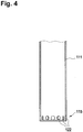
- Fig. 4 shows an end portion 115 of the conduit 111.
- the end portion 115 has openings 122 that are spread around the perimeter of the end portion 115 of the conduit 111.
- the end of the conduit 111 that faces the fluid outlet 116 may be closed such that the mixing volume is discharged through the openings 122 for causing a maximum swirl and mixing effect.
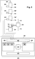
- Fig. 5 illustrates an automatic analyzer 200 according to an embodiment of the invention.
- This automatic analyzer is shown as having three cartridges 100, 100' and 100". At least one of the cartridges, such as cartridge 100, contains the fluid 104 with suspended and partly sedimented particles 113 in accordance with the embodiments of the Fig. 1 to 4 .
- the other cartridges 100' and 100" may be of identical or similar design and may contain fluids without sedimenting particles thus not requiring the compressible fluid pump of the Fig. 1 to 4 embodiments.
- actuator assembly 204 connected to cartridge 100.
- actuator assembly 204' attached to cartridge 100'.
- actuator assembly 204" attached to cartridge 100".
- the actuators 204, 204', 204" are for actuating the dispenser 118 of the cartridges 100, 100', 100".
- the automatic analyzer 200 is shown as having a relative movement means 210 which provides relative movement 212 between a receptacle 103 and the cartridges 100, 100' and 100".
- the receptacle 103 is shown as containing a biological sample 105.
- the cartridges 100, 100', 100" may be used to add one or more fluids to the biological sample 105.
- the automatic analyzer 200 may optionally comprise a measurement system 214.
- the measurement system may comprise one or more sensors for measuring a physical quantity or physical property of the biological sample 105.
- the measurement system 214 may comprise an NMR system, an optical transmission or reflectance measurement system, an electrochemical or optical sensor, a pH meter, a camera system or a chromatography system.
- the relative movement means 210 is also operable for moving the receptacle 103 to the measurement system 214.
- the arrangement of the cartridges 100, 100', 100" and the measurement system 214 is representative.
- the measurement system 214 may be alternatively also a part of the receptacle 103. In some embodiments the receptacle 103 may remain in a fixed position and the cartridges 100, 100', 100" may move.
- the actuation systems 204, 204', 204" and the measurement system 214 are shown as being connected to a hardware interface 222 of a computer system 220.
- the computer system 220 functions as a controller for the automatic analyzer 200.
- the computer 220 is further shown as containing a processor 224 which is able to control the operation and function of the automatic analyzer 200 using the hardware interface 222.
- the processor 224 is shown as further being connected to a user interface 226, computer storage 228 and computer memory 230.
- the computer storage 228 is shown as containing an analysis request 232.
- the analysis request 232 contains a request to analyze the biological sample 105.
- the computer storage 228 is shown as further containing sensor data 234 received from the measurement system 214.
- the computer storage 228 is shown as further containing an analysis result 236 which was determined using the sensor data 234.
- the computer memory 230 contains a control module 240.
- the control module 240 contains computer executable code which enables the processor 224 to control the operation and function of the automatic analyzer 200. For instance the control module 240 may use the analysis request 232 to generate commands to generate and send to the actuation systems 204, 204', 204", the measurement system 214 and the relative movement system 210. The control module 240 may also generate the analysis result 236 using the sensor data 234.
- the automatic analyzer 200 has an additional actuator assembly 205 that is coupled to the cartridge 100.
- the actuator assembly 205 acts upon the compressible fluid pump of the cartridge 100, e.g. on the bellows 109 (cf. Fig. 1 and Fig. 2 embodiments) or on the elastic membrane 120 (cf. Fig. 3 embodiment) if it receives a respective control signal from the control module 240.
- cartridges 100, 100' and 100" are releasably held by the automatic analyzer 200 for convenient replacement if they are empty and for directly dispensing from the cartridges without pipetting.
- the automatic analyzer that holds the cartridges 100, 100' and 100" performs the following steps for analyzing the biological sample 105:
- the computer system 220 may control the relative movement means 210 to place the receptacle 103 under the dispensers 118 of the cartridges 100' and 100" for dispensing respective amounts of fluids from the cartridge 100' and 100" into the receptacle 103.
- incubation is performed before a measurement step that is executed by the measurement system 214 for determination of the presence of an analyte within the biological sample 105.
Landscapes
- Health & Medical Sciences (AREA)
- Chemical & Material Sciences (AREA)
- Clinical Laboratory Science (AREA)
- Chemical Kinetics & Catalysis (AREA)
- Analytical Chemistry (AREA)
- Life Sciences & Earth Sciences (AREA)
- Physics & Mathematics (AREA)
- Biochemistry (AREA)
- General Health & Medical Sciences (AREA)
- General Physics & Mathematics (AREA)
- Immunology (AREA)
- Pathology (AREA)
- Automatic Analysis And Handling Materials Therefor (AREA)
Description
- The present invention relates to the field of fluidics, in particular cartridges for dispensing microfluidic portions of fluids for the purpose of performing an analysis of a biological sample.
- In medical laboratories, in vitro diagnostics are commonly performed on biological samples. Such tests may be performed manually using pipettes or maybe performed using an automatic analyzer. Automatic analyzers may automatically add reagents to the biological sample and may measure one or more physical properties of the biological sample during analysis. Automatic analyzers are known in the prior art. For example, European patent
EP 1 959 257 A2 discloses an automatic analyzer including a reagent cassette holding mechanism for holding a plurality of reagent cassettes.EP 1 959 257 A2 discloses that the analyzer has a reagent pipettor. The reagent pipettor is used for dispensing a reagent into a vessel containing a sample to initiate a chemical reaction. - International patent application publication
WO 2007/122387 discloses a cartridge for dispensing a reagent contained in a reagent reservoir. The cartridge comprises a reservoir which defines an enclosed gas space above the reagent. The cartridge further includes a gas vent that admits, in use, gas to the gas space. -
US 8318109 shows a microfluidic device for fluid manipulation and analyzing fluid samples. A bellows pump is fluidly connected to a microfluidic channel with a liquid barrier interposed between the bellows pump and an end of the microfluidic channel wherein the liquid barrier is gas permeable and liquid impermeable. -
US Patent 5,947,167 discloses a dispensing assembly with interchangeable cartridge pumps. Other fluid dispensers are disclosed inWO 2005/016534 A1 andWO 2007/122387 A2 . W. Streule et al., "PipeJet: A simple disposable dispenser for the nano- and microliter range", JALA, October 2004, pages 300-306 discloses a polymer tube clamped between two jaws. The backend of the tube is connected to a reservoir and serves as a supply channel. - The invention provides for a cartridge for dispensing a fluid, an automatic analyzer for analyzing a biological sample and a method of analyzing a biological sample for detecting an analyte as claimed in the independent claims. Embodiments of the invention are given in the dependent claims.
- Embodiments of the invention are particularly advantageous for storing and dispensing a fluid being a suspension containing particles that sediment on a bottom portion of the cartridge. Prior to dispensing a portion of the fluid for the purpose of performing an analysis the sedimented particles or at least a portion of the sedimented particles are suspended by a fluid flow that is directed towards the sedimented particles and mixes the particles with the fluid so that the particles are put back into suspensed state. In other words, the sedimented particles are resuspended by the fluid flow that is caused by discharging a mixing volume from the end of the conduit when the compressible fluid pump is compressed. This has the advantage that the concentration and distribution of the particles in the fluid fraction of the suspension reaches a predefined level before the dispensing volume is dispensed from the cartridge for the purpose of performing an analysis. This ensures that the analysis can be performed with a reproducible degree of precision.
- Embodiments of the invention are particularly advantageous as no rotating parts are required for mixing the sedimented particles with the fluid for re-suspending the sedimented particles within the fluid. This is accomplished by providing a single compressible fluid pump with a single elastic pumping element and an attached conduit extending from the fluid pump towards the fluid outlet which is particularly beneficial for microfluidic applications. Upon applying pressure onto the elastic pumping element the elastic pumping element is compressed, thereby compressing a pumping volume within the pumping element. The pressure on the pumping volume causes the pumping volume to move towards the conduit which ultimately leads to a flow of fluid from the conduit.
- In this case "elastic" means, that application of force or pressure onto the pumping element causes the pumping element to change its shape. However once the force or pressure vanishes the pumping element will return to its original shape by itself. Thus there is no need for additional means for preparing the pumping element for a subsequent pumping step. Note that the pumping element does not necessarily have to be made of elastic (that is reversibly deformable) material to be "elastic" as a whole. The pumping element may also be elastic because of its shape, for example if it is formed by bellows. An example for a pumping element being elastic because of its material would be an elastic membrane.
- In accordance with embodiments of the invention the reservoir chamber of the cartridge has a bottom portion forming a sink, the sink comprising the fluid outlet of the reservoir chamber and the conduit extending into the sink until a predetermined distance from the fluid outlet. This has the advantage of causing a fluid flow locally in this sink area by discharging the mixing volume from the conduit that is in proximity to the fluid outlet such that the local concentration and distribution of the particles in the suspension reaches its predefined level. During a dispensing step this portion of the fluid that is in proximity to the fluid outlet is dispensed such that the dispensing volume comprises the fluid with the resuspended particles in a defined concentration range. Another advantage is that the dead volume is limited so that the cartridge remains fully operational even when almost empty due to the fact that any remaining portion of the fluid is collected in the sink and can thus be mixed by the fluid flow caused by the pumping motion applied to the compressible fluid pump.
- In accordance with embodiments of the invention the cartridge has a baffle means forming a ventilation channel. In accordance with embodiments of the invention, the ventilation channel has a ventilation volume equal to or larger than the mixing volume that is dispensed by the fluid pump when the fluid pump is maximally compressed and therefore a maximum pumping volume is displaced by this compression. This has the advantage of minimizing the influx of ambient gases like oxygen or carbon dioxide from the surrounding atmosphere into the cartridge in order to limit degradation (e.g. by oxygenation) of the fluid contained in the reservoir chamber.
- A "cartridge" as understood herein comprises a receptacle for storing and dispensing a fluid. The cartridge has a mechanical interface that matches the mechanical interface of a holder of an automatic analyzer. The mechanical interfaces of the cartridge and the automatic analyzer enable mounting and release of the cartridge to and from the holder such that the cartridge can be conveniently replaced by a new cartridge when the cartridge is empty.
- In accordance with embodiments of the invention, the cartridge comprises a reservoir chamber for receiving and holding the fluid and the reservoir chamber is also operable for receiving a ventilation gas. The reservoir chamber comprises an inlet for receiving the ventilation gas. At least a portion of the reservoir chamber is operable for being filled with the ventilation gas when the cartridge is placed in an operating position. The inlet is located in the portion operable for being filled with the ventilation gas. The fluid comprises a reagent. The cartridge further comprises a baffle means for restricting gas diffusion through the inlet. The reservoir chamber receives the ventilation gas via the baffle means. Since the ventilation gas is provided directly to the gas within the reservoir, there is no formation of bubbles within the fluid fraction comprised within the reservoir chamber which otherwise could cause variations of the pressure within the reservoir chamber. In accordance with embodiments of the invention the baffle means provides the ventilation gas directly to the portion of the reservoir chamber operable for being filled with the ventilation gas. Embodiments of the invention may therefore have the advantage that there is always an equilibrium in pressure between outside of the cartridge and in the gas within the reservoir chamber. Embodiments of the invention may also have the advantage that the baffle means reduce the diffusion of gases into the reservoir chamber which may damage or degrade the fluid (e.g. if the reservoir chamber contains oxygen-sensitive reagents which may degrade by contact with the ambient air). The baffle means may also reduce evaporation of the fluid within the reservoir chamber because the diffusion of gas or vapor out of the reservoir chamber is also reduced.
- A "controller" as used herein encompasses a device, machine, or apparatus for controlling the operation and/or function of one or more other devices. Examples of a controller may include, but are not limited to: a computer, a processor, an imbedded system or controller, a programmable logic controller, and a microcontroller. A 'computing device' or 'computer' as used herein encompasses to any device comprising a processor. A 'processor' as used herein encompasses an electronic component which is able to execute a program or machine executable instruction.
- A 'hardware interface' as used herein encompasses a interface which enables a processor or other controller to interact with and/or control an external computing device and/or apparatus. A hardware interface may allow a processor to send control signals or instructions to an external computing device and/or apparatus.
- In one aspect the invention provides for a cartridge for dispensing a fluid. The cartridge comprises a reservoir chamber operable for receiving a fluid and for receiving a ventilation gas. A ventilation gas as used herein encompasses a gas which is used to equalize the pressure outside of the reservoir chamber and inside the reservoir chamber when fluid is removed from the reservoir chamber. The reservoir chamber comprises an inlet for receiving the ventilation gas and an outlet for dispensing the fluid. At least a portion of the reservoir chamber is operable for being filled with the ventilation gas when in an operating position. The inlet is located in the portion operable for being filled with the ventilation gas. In other words: When the cartridge is in an operating position, ventilation gas is added to the reservoir chamber at a location where there is already ventilation gas or which is immediately filled with the ventilation gas. The fluid comprises a reagent. A reagent as used herein is a substance or compound that is added to a (bio-)chemical system in order to initiate or facilitate a chemical or biochemical reaction or to identify or monitor if such a reaction occurs.
- In accordance with embodiments of the invention, the cartridge further comprises a baffle means for restricting gas diffusion through the inlet. The reservoir chamber is operable for receiving the ventilation gas via the baffle means. A baffle means as used herein encompasses a structure which causes gas to follow a particular path in order to reach the inlet. The baffle means provides a means of restricting the diffusion of gas in and/or out of the inlet. As such the gas diffusion as used herein may refer to the diffusion of ventilation gas into the cartridge and/or gas already present in the reservoir chamber from diffusing out. This embodiment may be advantageous because it may preserve the lifetime of the reagent within the cartridge. For instance depending upon the reagent constituents the ventilation gas may cause the reagent to lose effectiveness or to lose its chemical reactivity; also gas inside the reservoir chamber may contain vapors from the fluid. The baffle means restricts the diffusion of the fluid vapor out of the inlet also. This may help to prevent the concentration of a particular reagent from changing.
- In another embodiment the cartridge comprises a closing element like a cap. The closing element may be operable for being moved into an open position for opening the inlet and/or for enabling access to the pump. In some embodiments the closing element may seal the inlet directly, that is the sealing effect of the closing element is at the inlet. In other embodiments the closing element seals the baffle or a portion of the baffle. This indirectly seals the inlet.
- A closing element as used herein may in some embodiments be a mechanical part operable to open or close the inlet. Examples of closing elements may include, a removable piece of plastic, a piece of tape, and a mechanical part which is operable to interlock with the cartridge such as a screw cap. Also clamping elements which can close flexible parts of the baffle can be used as closing elements.
- In another embodiment the inlet is operable for maintaining a constant pressure within the portion of the reservoir chamber that is operable for being filled with the ventilation gas. This embodiment may be beneficial, because maintaining the pressure at a constant value enables more accurate dispensing of the fluid. In some embodiments the inlet is operable for maintaining a constant pressure within the portion of the reservoir chamber that is operable for being filled with the ventilation gas when dispensing fluid.
- For example, in Unites States patent application publication
US 2010/0015009 A1 an inlet which is submerged within the fluid is disclosed. Gas enters into the cartridge reservoir by bubbling at the inlet. - In some embodiments the ventilation gas may be normal atmospheric air. In some embodiments the baffle means is open to the atmosphere.
- In another embodiment the closing element is operable for being moved to an open position to open the inlet. The closing element may be removable or may be movable but fixed to the cartridge.
- In another embodiment the cartridge further comprises the fluid. i.e. is in a filled state.
- In another embodiment the fluid comprises a dispersion or suspension. A dispersion or suspension as used herein encompasses particles or particulates suspended within the fluid.
- In another embodiment the fluid may comprise latex particles.
- In another embodiment the fluid may comprise nanoparticles.
- In another embodiment the fluid may comprise magnetic particles.
- In another embodiment the cartridge further comprises a dispenser for dispensing the fluid. The dispenser is operable for receiving the fluid from the outlet of the reservoir chamber. In some embodiments the dispenser may be a microfluidic dispenser for dispensing a microfluidic portion of the fluid. In other embodiments the dispenser may comprise a nozzle. For instance the dispenser may comprise a straight tube or may comprise a nozzle with one or more valves contained within it.
- In another embodiment the dispenser is operable to dispense fluid at a rate independent of the baffle means. In other words the dispensing of the fluid is not regulated or controlled by the baffle means.
- For example in United States patent application
US 2011/030760 A1 an apparatus for controllably releasing a substance is disclosed. A regulator element restricts the flow of gas into the apparatus and effectively controls the release rate of a fluid. In contrast to this, in some embodiments of the invention fluid can be dispensed at a rate that is effectively independent of the baffle means. The baffle means according to some embodiments of the invention may have such a small effect on the rate of dispensing that the effect is much smaller than the actual volume dispensed. This may enable more accurate dispensing of the fluid. - In another embodiment the dispenser is a micro-fluidic dispensing assembly.
- In another embodiment the dispenser is operable for dispensing any one of the following: volumes less than 10 µL, less than 500 nL, less than 200 nL, less than 100 nL, and less than 20 nL.
- The invention provides for an automatic analyzer comprising the cartridge and comprising a holder for holding or receiving a cartridge according to an embodiment of the invention. The automatic analyzer comprises an actuator assembly operable for actuating the dispenser. The automatic analyzer also comprises an actuator assembly operable for actuating the fluid pump. The automatic analyzer further comprises a controller for controlling the operation of the actuator assembly and the fluid pump.
- The dispenser and the fluid pump may be mechanically, pneumatically, magnetically, and/or electrically actuated. This is dependent upon the implementation and how the dispenser is constructed. In an embodiment the cartridge is in an operating position when installed into the automatic analyzer.
- In the following, embodiments of the invention will be described in greater detail, by way of example only, making reference to the drawings in which:
- Fig. 1
- shows a cross-sectional view of an embodiment of the cartridge according to the invention,
- Fig. 2
- shows an alternative embodiment of the cartridge where the bellows are integrated into the housing of the cartridge,
- Fig. 3
- shows an alternative embodiment of the cartridge having a membrane instead of bellows,
- Fig. 4
- schematically shows an end portion of a conduit in accordance with an embodiment of the invention,
- Fig. 5
- is a block diagram of an embodiment of an automatic analyzer in accordance with the invention,
- Fig. 6
- shows an alternative embodiment of the cartridge without a baffle means and flexible reservoir chamber walls.
- Throughout the following description of the various embodiments identical reference numbers are utilized for designating like or identical elements.
-
Fig. 1 illustrates acartridge 100 according to an embodiment of the invention. Thecartridge 100 comprises areservoir chamber 102 for holding afluid 104. Thereservoir chamber 102 is only partially filled with thefluid 104. There is a region filled withgas 106, such as air, at the top of thereservoir chamber 102. - Adjacent to the
reservoir chamber 102 is a baffle means 108. The baffle means 108 in this example has a vent-to-atmosphere 110. Traveling through the baffle means there is anoptional gas filter 112 which covers aninlet 114 to thereservoir chamber 102. Theinlet 114 provides ventilation gas to the gas filledportion 106 of thereservoir chamber 102. Theinlet 114 is attached to the baffle means 108. - The fluid 104 exits the
reservoir chamber 102 via anoutlet 116. In this example there is adispenser 118. Thedispenser 118 may comprise a nozzle or tube for dispensing the fluid when it is actuated by an external device, such as by an actuator assembly of an analyzer (cf. the embodiment ofFig. 5 ). - The
dispenser 118 serves for dispensing a dispensingvolume 101 into areceptacle 103. For example, the dispensingvolume 101 of a reagent fluid contained within the reservoir chamber is mixed with abiological sample 105 contained in thereceptacle 103 for performing an analysis for detecting an analyte. - The
dispenser 118 is connected to thefluid outlet 116 of thereservoir chamber 102. - The
cartridge 100 has afluid pump 107 that comprisesbellows 109 forming an elastic pumping element outside the housing of thecartridge 100. Thebellows 109 are connected to aconduit 111 that extends from the bellows towards thefluid outlet 116. - In the embodiment considered here the fluid 104 is a suspension containing particles. A portion of the particles, i.e.
particles 113, forms a sediment on a bottom portion of thereservoir chamber 102. In order to re-suspend the sedimentedparticles 113 thebellows 109 are compressed such as by an actuator of an analyzer that holds the cartridge 100 (cf. the embodiment ofFig. 5 ) (or in an alternative element also manually), such that a mixingvolume 124 of fluid is discharged from theend portion 115 of theconduit 111 that causes a fluid flow mixing the sedimentedparticles 113 with the fluid 104, thus re-suspending theparticles 113. - When the
bellows 109 are released they decompress and suck in the previously discharged mixingvolume 124 from the fluid 104 contained in thereservoir chamber 102 to prepare for the next mixing cycle. - In accordance with an embodiment of the invention the
conduit 111 is tube- or pipette-shaped as shown inFig. 1 . Alternatively theconduit 111 may have a curved form. For example, thebellows 109 may be arranged on a side of the housing of thecartridge 100 rather than on the top. In this instance the geometry of thecartridge 100 may require theconduit 111 to have a curved form. - In the embodiment considered here the
reservoir chamber 102 has a bottom portion that forms thesink 117 which comprises thefluid outlet 116. Theconduit 111 extends into thesink 117 until a predetermined distance d from thefluid outlet 116. For example the distance d may be in the range of 1 mm to 10 mm, preferably 3 mm. This has the advantage that the fluid flow that is caused by discharging the mixing volume from theend portion 115 of theconduit 111 is concentrated within thesink 117 for re-suspending the sedimentedparticles 113 that have sedimented on the bottom of thesink 117. This causes an intense mixing and re-suspending of the particles in this portion of the reservoir chamber. In a next step after finalization of the mixing process, a portion of the fluid 104 that is in thesink 117 is dispensed as dispensingvolume 101 by thedispenser 118. - In accordance with embodiments of the invention the
reservoir chamber 102 and the pump that is constituted by thebellows 109 and theconduit 111 is a single form piece, such as an injection molded piece, that is produced such as by two component injection molding. For example, thereservoir chamber 102 may consist of polypropylene and the pump, i.e. the bellows and theconduit 111, may consist of polyethylene. In still another embodiment the bellows may be a single form piece with the cover of the cartridge. - The
particles 113 contained in the fluid 104 may comprise magnetic beads such as streptavidine-coated magnetic beads that are required for performing an electrochemiluminescence analysis. In alternative embodiments (e.g. for clinical chemistry tests), also coated latex particles can be used asparticles 113. The fluid 104 may be any particle enhanced immunoassay reagent comprising suspended particles that may sediment after some storage time. - In accordance with an embodiment of the invention the volume of air contained in the baffle means 108 is equal or larger than the
maximum mixing volume 124 that is discharged when thebellows 109 are maximally compressed. This is to avoid or reduce the influx of air from the surrounding atmosphere into thereservoir chamber 102 when a pumping cycle is executed. - In accordance with other embodiments of the invention the walls of the reservoir chamber can be flexible. These walls expand when the fluid pump is compressed (and the additional mixing volume is pressed into the reservoir chamber) and shrink when the fluid pump is decompressed and when fluid 104 is dispensed so that no baffle means is required. Such an embodiment without a baffle means is shown in
Fig. 6 . The dashed lines show the variation of the volume of thereservoir chamber 102 during a pumping cycle. -
Fig. 2 shows an alternative embodiment where thebellows 109 are integrated within the housing of thecartridge 100. The housing of thecartridge 100 may have a top portion with anopening 119 through which thebellows 109 is accessible for compression. For example an actuator of an automatic analyzer can be inserted into theopening 119 for compressing thebellows 109. As a further alternative a cap as a closing element may be placed into or onto theopening 119 for transportation of thecartridge 100. The cap is removed from theopening 119 when thecartridge 100 is put into a holder of the automatic analyzer. Removal of the cap may also open the vent toatmosphere 110. The embodiment ofFig 2 has the advantage that the pumping element defined by the bellows is integrated within the housing of the cartridge for easier packaging, transportation, mounting and releasing from the holder of the analyzer. -
Fig. 3 shows a further embodiment of thecartridge 100 where the elastic pumping element is anelastic membrane 120. By means of an external actuator themembrane 120 can be deformed to extend into the inside of theconduit 111 for compressing the pumping volume as shown by the dotted lines inFig. 3 . -
Fig. 4 shows anend portion 115 of theconduit 111. Theend portion 115 hasopenings 122 that are spread around the perimeter of theend portion 115 of theconduit 111. The end of theconduit 111 that faces thefluid outlet 116 may be closed such that the mixing volume is discharged through theopenings 122 for causing a maximum swirl and mixing effect. -
Fig. 5 illustrates anautomatic analyzer 200 according to an embodiment of the invention. This automatic analyzer is shown as having threecartridges cartridge 100, contains the fluid 104 with suspended and partly sedimentedparticles 113 in accordance with the embodiments of theFig. 1 to 4 . Theother cartridges 100' and 100" may be of identical or similar design and may contain fluids without sedimenting particles thus not requiring the compressible fluid pump of theFig. 1 to 4 embodiments. - There is an
actuator assembly 204 connected tocartridge 100. There is an actuator assembly 204' attached to cartridge 100'. There is anactuator assembly 204" attached tocartridge 100". Theactuators dispenser 118 of thecartridges - The
automatic analyzer 200 is shown as having a relative movement means 210 which providesrelative movement 212 between areceptacle 103 and thecartridges receptacle 103 is shown as containing abiological sample 105. Thecartridges biological sample 105. Theautomatic analyzer 200 may optionally comprise ameasurement system 214. The measurement system may comprise one or more sensors for measuring a physical quantity or physical property of thebiological sample 105. For example themeasurement system 214 may comprise an NMR system, an optical transmission or reflectance measurement system, an electrochemical or optical sensor, a pH meter, a camera system or a chromatography system. The relative movement means 210 is also operable for moving thereceptacle 103 to themeasurement system 214. - The arrangement of the
cartridges measurement system 214 is representative. Themeasurement system 214 may be alternatively also a part of thereceptacle 103. In some embodiments thereceptacle 103 may remain in a fixed position and thecartridges actuation systems measurement system 214 are shown as being connected to ahardware interface 222 of acomputer system 220. Thecomputer system 220 functions as a controller for theautomatic analyzer 200. - The
computer 220 is further shown as containing aprocessor 224 which is able to control the operation and function of theautomatic analyzer 200 using thehardware interface 222. Theprocessor 224 is shown as further being connected to auser interface 226,computer storage 228 andcomputer memory 230. Thecomputer storage 228 is shown as containing ananalysis request 232. Theanalysis request 232 contains a request to analyze thebiological sample 105. - The
computer storage 228 is shown as further containingsensor data 234 received from themeasurement system 214. Thecomputer storage 228 is shown as further containing ananalysis result 236 which was determined using thesensor data 234. Thecomputer memory 230 contains acontrol module 240. Thecontrol module 240 contains computer executable code which enables theprocessor 224 to control the operation and function of theautomatic analyzer 200. For instance thecontrol module 240 may use theanalysis request 232 to generate commands to generate and send to theactuation systems measurement system 214 and therelative movement system 210. Thecontrol module 240 may also generate theanalysis result 236 using thesensor data 234. - The
automatic analyzer 200 has anadditional actuator assembly 205 that is coupled to thecartridge 100. Theactuator assembly 205 acts upon the compressible fluid pump of thecartridge 100, e.g. on the bellows 109 (cf.Fig. 1 andFig. 2 embodiments) or on the elastic membrane 120 (cf.Fig. 3 embodiment) if it receives a respective control signal from thecontrol module 240. - It is important to note that the
cartridges automatic analyzer 200 for convenient replacement if they are empty and for directly dispensing from the cartridges without pipetting. - In operation the automatic analyzer that holds the
cartridges - a. The
computer system 220 controls the relative movement means 210 to place thereceptacle 103 underneath thedispenser 118 of thecartridge 100. - b. The
computer system 220 controls theactuator assembly 205 that is coupled to thecartridge 100 to compress the elastic pumping element of the fluid pump of thecartridge 100 such that anyparticles 113 of the fluid 104 that may have sedimented are resuspended due to the mixing that is caused by discharging the mixing volume 124 (cf.Fig. 1 to 3 ) from theconduit 111. Such a compression/depression cycle of the elastic pumping element can be repeated multiple times to ensure a defined and reproducible mixing of the particles within the fluid. - c. The
actuator assembly 204 is controlled by thecomputer system 220 to act upon thedispenser 118 to dispense a required amount of the fluid 104 into thereceptacle 103 for mixing with thebiological sample 105. - In the following, the
computer system 220 may control the relative movement means 210 to place thereceptacle 103 under thedispensers 118 of thecartridges 100' and 100" for dispensing respective amounts of fluids from thecartridge 100' and 100" into thereceptacle 103. Depending on the kind of analysis that is performed, such as an electrochemiluminescence analysis, incubation is performed before a measurement step that is executed by themeasurement system 214 for determination of the presence of an analyte within thebiological sample 105. -
- 100
- cartridge
- 101
- dispensing volume
- 102
- reservoir chamber
- 103
- receptacle
- 104
- fluid
- 105
- biological sample
- 106
- gas
- 107
- fluid pump
- 108
- baffle means
- 109
- bellows
- 110
- vent to atmosphere
- 111
- conduit
- 112
- gas filter
- 113
- particles
- 114
- inlet
- 115
- end portion
- 116
- outlet
- 117
- sink
- 118
- dispenser
- 119
- opening
- 120
- membrane
- 122
- openings
- 200
- automatic analyzer
- 100
- cartridge
- 100'
- cartridge
- 100"
- cartridge
- 204
- actuator assembly
- 204'
- actuator assembly
- 204"
- actuator assembly
- 205
- actuator assembly
- 210
- relative movement means
- 212
- relative movement
- 214
- measurement system
- 220
- computer
- 222
- hardware interface
- 224
- processor
- 226
- user interface
- 228
- computer storage
- 230
- computer memory
- 232
- analysis request
- 234
- sensor data
- 236
- analysis result
- 240
- control module
Claims (15)
- A cartridge (100) for dispensing a fluid (104), wherein the cartridge comprises:- a reservoir chamber (102) operable for receiving the fluid, the reservoir chamber having a fluid outlet (116),- a controllable dispenser component (118) for dispensing a dispensing volume (101) of the fluid from the reservoir chamber, the dispenser component being connected to the fluid outlet of the reservoir,- a single compressible fluid pump (107) with a single elastic pumping element (109, 120),- a conduit (111) extending from the fluid pump towards the fluid outlet,the fluid pump (107) being operable to discharge a mixing volume (124) of the fluid (104) from the conduit (111) into the reservoir chamber (102) upon compression of the elastic pumping element, the mixing volume (124) depending on the degree of compression of the elastic pumping element, and the fluid pump (107) being operable to suck in the mixing volume (124) from the reservoir (102) into the conduit (111) upon decompression of the elastic pumping element.
- The cartridge of claim 1, the elastic pumping element being formed by bellows (109).
- The cartridge of claim 1, the elastic pumping element being an elastic membrane (120).
- The cartridge of claim 1, 2 or 3, the conduit being tube- or pipette-shaped.
- The cartridge of any one of the preceding claims, the reservoir chamber having a bottom portion forming a sink (117), the sink comprising the fluid outlet of the reservoir chamber, the conduit extending into the sink until a predetermined distance (d) from the fluid outlet.
- The cartridge of claim 5, wherein the distance d is in the range from 1 mm to 10 mm.
- The cartridge of claim 5 or 6, the conduit having an end portion (115) facing the outlet, the end portion having multiple openings (122) spread around the perimeter of the end portion for discharging the mixing volume.
- The cartridge of any one of the preceding claims, the reservoir chamber further comprising an inlet (114) for receiving a ventilation gas (106) wherein the inlet is operable for maintaining a constant gas pressure within the reservoir chamber when the fluid is dispensed.
- The cartridge of claim 8, the reservoir chamber further comprising baffle means (108) for restricting gas diffusion through the inlet, the baffle means forming a ventilation channel, the ventilation channel having a ventilation volume equal to or greater than the mixing volume that results from a maximum compression of the elastic pumping element.
- The cartridge of any of the claims 1-7, wherein the walls of the reservoir chamber are flexible and wherein the reservoir chamber is designed to expand upon compression of the elastic pumping element and to shrink upon decompression of the elastic pumping element.
- The cartridge of any one of the preceding claims, the reservoir chamber being at least partly filled with the fluid, the fluid being a dispersion or a suspension containing particles that sediment on a bottom portion of the reservoir.
- The cartridge of claim 11, the particles being magnetic beads, such as magnetized polystyrene beads, the particles preferably having a diameter between 1 and 4 µm, preferably between 2 and 3 µm and/or the particles being latex-beads, the particles having a diameter between 0,05 µm and 0,4 µm, the beads preferably being streptavidine-coated for binding a biotinylated antibody.
- An automatic analyzer (200) for analyzing a biological sample (105), the automatic analyzer comprising a cartridge (100) in accordance with any one of the preceding claims, a holder for holding said cartridge in an operating position, and further comprising a first actuator assembly (204) operable for actuating the dispenser component (118) of the cartridge for controlling the dispenser component to dispense the dispensing volume (101), the automatic analyzer being operable to perform an analysis of the biological sample for detecting an analyte using the dispensing volume, the automatic analyzer further comprising a second actuator assembly (205) for compressing the elastic pumping element of the cartridge, and a controller (220, 240) for controlling the second actuator assembly for compressing the elastic pumping element prior to controlling the first actuator assembly for dispensing the dispensing volume.
- A method of analyzing a biological sample (105) for detecting an analyte comprising:- providing an automatic analyzer (200) in accordance with claim 13 holding a cartridge (100) in accordance with any one of the preceding claims 10, 11 or 12,- controlling the second actuator assembly (205) by the controller for compressing the elastic pumping element such that the mixing volume (124) is discharged from the end portion (115) of the conduit for resuspending sedimented particles,- controlling the first actuator assembly (204) by the controller for dispensing the dispensing volume (101) of the fluid,- performing an analysis by the automatic analyzer for detecting the analyte using the dispensed volume of the fluid.
- The method of claim 14, wherein the second actuator assembly (205) may be controlled such that the elastic pumping element is repeatedly compressed and released until the sedimented particles are sufficiently resuspended for performing the analysis.
Priority Applications (1)
| Application Number | Priority Date | Filing Date | Title |
|---|---|---|---|
| EP14742198.6A EP3030352B1 (en) | 2013-08-07 | 2014-07-18 | Cartridge for dispensing a fluid, automatic analyser and method of analysing a biological sample |
Applications Claiming Priority (3)
| Application Number | Priority Date | Filing Date | Title |
|---|---|---|---|
| EP13179523 | 2013-08-07 | ||
| EP14742198.6A EP3030352B1 (en) | 2013-08-07 | 2014-07-18 | Cartridge for dispensing a fluid, automatic analyser and method of analysing a biological sample |
| PCT/EP2014/065482 WO2015018626A1 (en) | 2013-08-07 | 2014-07-18 | Cartridge for dispensing a fluid, automatic analyzer and method of analyzing a biological sample |
Publications (2)
| Publication Number | Publication Date |
|---|---|
| EP3030352A1 EP3030352A1 (en) | 2016-06-15 |
| EP3030352B1 true EP3030352B1 (en) | 2019-03-20 |
Family
ID=48917438
Family Applications (1)
| Application Number | Title | Priority Date | Filing Date |
|---|---|---|---|
| EP14742198.6A Active EP3030352B1 (en) | 2013-08-07 | 2014-07-18 | Cartridge for dispensing a fluid, automatic analyser and method of analysing a biological sample |
Country Status (5)
| Country | Link |
|---|---|
| US (1) | US10018644B2 (en) |
| EP (1) | EP3030352B1 (en) |
| JP (1) | JP6560671B2 (en) |
| CN (1) | CN105377434B (en) |
| WO (1) | WO2015018626A1 (en) |
Families Citing this family (9)
| Publication number | Priority date | Publication date | Assignee | Title |
|---|---|---|---|---|
| EP3514519B1 (en) | 2009-12-07 | 2022-02-09 | Meso Scale Technologies, LLC. | Assay cartridges |
| EP3098606A1 (en) * | 2015-05-29 | 2016-11-30 | Roche Diagniostics GmbH | Cartridge for dispensing particles and a reagent fluid |
| JP2017156249A (en) * | 2016-03-02 | 2017-09-07 | アークレイ株式会社 | Dispensing device, measuring system including the same, and dispensing method |
| JP6879359B2 (en) * | 2017-03-28 | 2021-06-02 | 日本電気株式会社 | Microtube |
| CN112638536B (en) * | 2018-09-03 | 2022-08-09 | 京瓷株式会社 | Pipette and liquid extraction method |
| CN114025880B (en) * | 2019-04-26 | 2023-10-10 | 斯蒂拉科技公司 | Polymerase chain reaction apparatus and method for pressure controlled release of fluid |
| US11458476B2 (en) * | 2019-10-17 | 2022-10-04 | Marvin Liu | In-situ fecal specimen sampling device |
| JP7174741B2 (en) * | 2020-08-31 | 2022-11-17 | ピコテクバイオ株式会社 | Micro-sampling chip and inspection device using the micro-sampling chip |
| CN119776116B (en) * | 2025-03-10 | 2025-05-09 | 湖南中瑞互信医疗科技有限公司 | Shaking table device is hatched to constant temperature |
Family Cites Families (16)
| Publication number | Priority date | Publication date | Assignee | Title |
|---|---|---|---|---|
| JPS5239261Y2 (en) * | 1974-03-07 | 1977-09-06 | ||
| US4392860A (en) * | 1979-01-11 | 1983-07-12 | Howmedica, Inc. | Disposable wound drainage device |
| JPH0120696Y2 (en) * | 1980-12-15 | 1989-06-21 | ||
| US4852620A (en) * | 1988-04-20 | 1989-08-01 | Eastman Kodak Company | Pipette with inverted bellows |
| US5947167A (en) | 1992-05-11 | 1999-09-07 | Cytologix Corporation | Dispensing assembly with interchangeable cartridge pumps |
| JP3276551B2 (en) * | 1995-12-19 | 2002-04-22 | シスメックス株式会社 | Sample stirring / suction device |
| KR20000031769A (en) * | 1998-11-10 | 2000-06-05 | 박경서 | Spring water pump |
| DE19943121A1 (en) * | 1999-09-09 | 2001-03-15 | Lre Technology Partner Gmbh | Dosing device for precise dispensing of small fluid quantities has an arrangement of two pumps connected to a controller so that the outlet of one pump and the suction of the other pump are connected to a dispensing pipette |
| US20020168297A1 (en) * | 2001-05-11 | 2002-11-14 | Igor Shvets | Method and device for dispensing of droplets |
| US7419638B2 (en) | 2003-01-14 | 2008-09-02 | Micronics, Inc. | Microfluidic devices for fluid manipulation and analysis |
| JP2004325117A (en) * | 2003-04-22 | 2004-11-18 | Olympus Corp | Liquid dispensing apparatus and method of washing dispensing head |
| DE10337484B4 (en) * | 2003-08-14 | 2005-05-25 | Zengerle, Roland, Prof. Dr. | Microdosing device and method for the metered dispensing of liquids |
| GB0607427D0 (en) | 2006-04-13 | 2006-05-24 | Imi Vision Ltd | Fluid dispenser |
| JP4901862B2 (en) * | 2006-05-09 | 2012-03-21 | 平田機工株式会社 | Microplate mounting table and specimen inspection / observation apparatus equipped with the mounting table |
| JP4500822B2 (en) | 2007-02-19 | 2010-07-14 | 株式会社日立ハイテクノロジーズ | Automatic analyzer |
| DE212009000047U1 (en) | 2008-04-18 | 2011-03-17 | Oerlikon Trading Ag, Trübbach | Photovoltaic device |
-
2014
- 2014-07-18 EP EP14742198.6A patent/EP3030352B1/en active Active
- 2014-07-18 CN CN201480025798.3A patent/CN105377434B/en active Active
- 2014-07-18 WO PCT/EP2014/065482 patent/WO2015018626A1/en not_active Ceased
- 2014-07-18 JP JP2016532296A patent/JP6560671B2/en not_active Expired - Fee Related
-
2016
- 2016-01-26 US US15/006,476 patent/US10018644B2/en active Active
Non-Patent Citations (1)
| Title |
|---|
| None * |
Also Published As
| Publication number | Publication date |
|---|---|
| CN105377434B (en) | 2017-07-28 |
| US10018644B2 (en) | 2018-07-10 |
| JP2016525698A (en) | 2016-08-25 |
| WO2015018626A1 (en) | 2015-02-12 |
| JP6560671B2 (en) | 2019-08-14 |
| US20160139164A1 (en) | 2016-05-19 |
| CN105377434A (en) | 2016-03-02 |
| EP3030352A1 (en) | 2016-06-15 |
Similar Documents
| Publication | Publication Date | Title |
|---|---|---|
| US10018644B2 (en) | Cartridge for dispensing a fluid, automatic analyzer and method of analyzing a biological sample | |
| EP2662671B1 (en) | Cartridge for dispensing a fluid | |
| US9808801B2 (en) | Rotatable cartridge for measuring a property of a biological sample | |
| EP2662138A1 (en) | Microfluidic dispenser, cartridge and analysis system for analyzing a biological sample | |
| US10241124B2 (en) | Method to perform a measurement of an analyte in a sample using an automatic analyzer | |
| US9573131B2 (en) | Cartridge for dispensing a fluid comprising a reagent | |
| EP3304094A1 (en) | Cartridge for dispensing particles and a reagent fluid | |
| US10345322B2 (en) | Cartridge for stirring and dispensing a fluid, automatic analyzer and method of analyzing a biological sample | |
| HK1205261B (en) | Cartridge for dispensing a fluid comprising a reagent | |
| HK1208261B (en) | Cartridge for dispensing a fluid |
Legal Events
| Date | Code | Title | Description |
|---|---|---|---|
| PUAI | Public reference made under article 153(3) epc to a published international application that has entered the european phase |
Free format text: ORIGINAL CODE: 0009012 |
|
| 17P | Request for examination filed |
Effective date: 20160307 |
|
| AK | Designated contracting states |
Kind code of ref document: A1 Designated state(s): AL AT BE BG CH CY CZ DE DK EE ES FI FR GB GR HR HU IE IS IT LI LT LU LV MC MK MT NL NO PL PT RO RS SE SI SK SM TR |
|
| AX | Request for extension of the european patent |
Extension state: BA ME |
|
| DAX | Request for extension of the european patent (deleted) | ||
| RIC1 | Information provided on ipc code assigned before grant |
Ipc: G01N 35/10 20060101ALI20180903BHEP Ipc: B01L 3/02 20060101AFI20180903BHEP |
|
| GRAP | Despatch of communication of intention to grant a patent |
Free format text: ORIGINAL CODE: EPIDOSNIGR1 |
|
| STAA | Information on the status of an ep patent application or granted ep patent |
Free format text: STATUS: GRANT OF PATENT IS INTENDED |
|
| INTG | Intention to grant announced |
Effective date: 20181015 |
|
| GRAS | Grant fee paid |
Free format text: ORIGINAL CODE: EPIDOSNIGR3 |
|
| GRAA | (expected) grant |
Free format text: ORIGINAL CODE: 0009210 |
|
| STAA | Information on the status of an ep patent application or granted ep patent |
Free format text: STATUS: THE PATENT HAS BEEN GRANTED |
|
| AK | Designated contracting states |
Kind code of ref document: B1 Designated state(s): AL AT BE BG CH CY CZ DE DK EE ES FI FR GB GR HR HU IE IS IT LI LT LU LV MC MK MT NL NO PL PT RO RS SE SI SK SM TR |
|
| REG | Reference to a national code |
Ref country code: GB Ref legal event code: FG4D |
|
| REG | Reference to a national code |
Ref country code: CH Ref legal event code: EP |
|
| REG | Reference to a national code |
Ref country code: DE Ref legal event code: R096 Ref document number: 602014043250 Country of ref document: DE |
|
| REG | Reference to a national code |
Ref country code: AT Ref legal event code: REF Ref document number: 1110001 Country of ref document: AT Kind code of ref document: T Effective date: 20190415 |
|
| REG | Reference to a national code |
Ref country code: IE Ref legal event code: FG4D |
|
| REG | Reference to a national code |
Ref country code: NL Ref legal event code: MP Effective date: 20190320 |
|
| PG25 | Lapsed in a contracting state [announced via postgrant information from national office to epo] |
Ref country code: SE Free format text: LAPSE BECAUSE OF FAILURE TO SUBMIT A TRANSLATION OF THE DESCRIPTION OR TO PAY THE FEE WITHIN THE PRESCRIBED TIME-LIMIT Effective date: 20190320 Ref country code: LT Free format text: LAPSE BECAUSE OF FAILURE TO SUBMIT A TRANSLATION OF THE DESCRIPTION OR TO PAY THE FEE WITHIN THE PRESCRIBED TIME-LIMIT Effective date: 20190320 Ref country code: NO Free format text: LAPSE BECAUSE OF FAILURE TO SUBMIT A TRANSLATION OF THE DESCRIPTION OR TO PAY THE FEE WITHIN THE PRESCRIBED TIME-LIMIT Effective date: 20190620 Ref country code: FI Free format text: LAPSE BECAUSE OF FAILURE TO SUBMIT A TRANSLATION OF THE DESCRIPTION OR TO PAY THE FEE WITHIN THE PRESCRIBED TIME-LIMIT Effective date: 20190320 |
|
| REG | Reference to a national code |
Ref country code: LT Ref legal event code: MG4D |
|
| PG25 | Lapsed in a contracting state [announced via postgrant information from national office to epo] |
Ref country code: BG Free format text: LAPSE BECAUSE OF FAILURE TO SUBMIT A TRANSLATION OF THE DESCRIPTION OR TO PAY THE FEE WITHIN THE PRESCRIBED TIME-LIMIT Effective date: 20190620 Ref country code: RS Free format text: LAPSE BECAUSE OF FAILURE TO SUBMIT A TRANSLATION OF THE DESCRIPTION OR TO PAY THE FEE WITHIN THE PRESCRIBED TIME-LIMIT Effective date: 20190320 Ref country code: LV Free format text: LAPSE BECAUSE OF FAILURE TO SUBMIT A TRANSLATION OF THE DESCRIPTION OR TO PAY THE FEE WITHIN THE PRESCRIBED TIME-LIMIT Effective date: 20190320 Ref country code: NL Free format text: LAPSE BECAUSE OF FAILURE TO SUBMIT A TRANSLATION OF THE DESCRIPTION OR TO PAY THE FEE WITHIN THE PRESCRIBED TIME-LIMIT Effective date: 20190320 Ref country code: GR Free format text: LAPSE BECAUSE OF FAILURE TO SUBMIT A TRANSLATION OF THE DESCRIPTION OR TO PAY THE FEE WITHIN THE PRESCRIBED TIME-LIMIT Effective date: 20190621 Ref country code: HR Free format text: LAPSE BECAUSE OF FAILURE TO SUBMIT A TRANSLATION OF THE DESCRIPTION OR TO PAY THE FEE WITHIN THE PRESCRIBED TIME-LIMIT Effective date: 20190320 |
|
| REG | Reference to a national code |
Ref country code: AT Ref legal event code: MK05 Ref document number: 1110001 Country of ref document: AT Kind code of ref document: T Effective date: 20190320 |
|
| PG25 | Lapsed in a contracting state [announced via postgrant information from national office to epo] |
Ref country code: IT Free format text: LAPSE BECAUSE OF FAILURE TO SUBMIT A TRANSLATION OF THE DESCRIPTION OR TO PAY THE FEE WITHIN THE PRESCRIBED TIME-LIMIT Effective date: 20190320 Ref country code: SK Free format text: LAPSE BECAUSE OF FAILURE TO SUBMIT A TRANSLATION OF THE DESCRIPTION OR TO PAY THE FEE WITHIN THE PRESCRIBED TIME-LIMIT Effective date: 20190320 Ref country code: PT Free format text: LAPSE BECAUSE OF FAILURE TO SUBMIT A TRANSLATION OF THE DESCRIPTION OR TO PAY THE FEE WITHIN THE PRESCRIBED TIME-LIMIT Effective date: 20190720 Ref country code: AL Free format text: LAPSE BECAUSE OF FAILURE TO SUBMIT A TRANSLATION OF THE DESCRIPTION OR TO PAY THE FEE WITHIN THE PRESCRIBED TIME-LIMIT Effective date: 20190320 Ref country code: EE Free format text: LAPSE BECAUSE OF FAILURE TO SUBMIT A TRANSLATION OF THE DESCRIPTION OR TO PAY THE FEE WITHIN THE PRESCRIBED TIME-LIMIT Effective date: 20190320 Ref country code: RO Free format text: LAPSE BECAUSE OF FAILURE TO SUBMIT A TRANSLATION OF THE DESCRIPTION OR TO PAY THE FEE WITHIN THE PRESCRIBED TIME-LIMIT Effective date: 20190320 Ref country code: CZ Free format text: LAPSE BECAUSE OF FAILURE TO SUBMIT A TRANSLATION OF THE DESCRIPTION OR TO PAY THE FEE WITHIN THE PRESCRIBED TIME-LIMIT Effective date: 20190320 Ref country code: ES Free format text: LAPSE BECAUSE OF FAILURE TO SUBMIT A TRANSLATION OF THE DESCRIPTION OR TO PAY THE FEE WITHIN THE PRESCRIBED TIME-LIMIT Effective date: 20190320 |
|
| PG25 | Lapsed in a contracting state [announced via postgrant information from national office to epo] |
Ref country code: SM Free format text: LAPSE BECAUSE OF FAILURE TO SUBMIT A TRANSLATION OF THE DESCRIPTION OR TO PAY THE FEE WITHIN THE PRESCRIBED TIME-LIMIT Effective date: 20190320 Ref country code: PL Free format text: LAPSE BECAUSE OF FAILURE TO SUBMIT A TRANSLATION OF THE DESCRIPTION OR TO PAY THE FEE WITHIN THE PRESCRIBED TIME-LIMIT Effective date: 20190320 |
|
| PG25 | Lapsed in a contracting state [announced via postgrant information from national office to epo] |
Ref country code: IS Free format text: LAPSE BECAUSE OF FAILURE TO SUBMIT A TRANSLATION OF THE DESCRIPTION OR TO PAY THE FEE WITHIN THE PRESCRIBED TIME-LIMIT Effective date: 20190720 Ref country code: AT Free format text: LAPSE BECAUSE OF FAILURE TO SUBMIT A TRANSLATION OF THE DESCRIPTION OR TO PAY THE FEE WITHIN THE PRESCRIBED TIME-LIMIT Effective date: 20190320 |
|
| REG | Reference to a national code |
Ref country code: DE Ref legal event code: R097 Ref document number: 602014043250 Country of ref document: DE |
|
| PLBE | No opposition filed within time limit |
Free format text: ORIGINAL CODE: 0009261 |
|
| STAA | Information on the status of an ep patent application or granted ep patent |
Free format text: STATUS: NO OPPOSITION FILED WITHIN TIME LIMIT |
|
| PG25 | Lapsed in a contracting state [announced via postgrant information from national office to epo] |
Ref country code: DK Free format text: LAPSE BECAUSE OF FAILURE TO SUBMIT A TRANSLATION OF THE DESCRIPTION OR TO PAY THE FEE WITHIN THE PRESCRIBED TIME-LIMIT Effective date: 20190320 |
|
| 26N | No opposition filed |
Effective date: 20200102 |
|
| PG25 | Lapsed in a contracting state [announced via postgrant information from national office to epo] |
Ref country code: MC Free format text: LAPSE BECAUSE OF FAILURE TO SUBMIT A TRANSLATION OF THE DESCRIPTION OR TO PAY THE FEE WITHIN THE PRESCRIBED TIME-LIMIT Effective date: 20190320 Ref country code: SI Free format text: LAPSE BECAUSE OF FAILURE TO SUBMIT A TRANSLATION OF THE DESCRIPTION OR TO PAY THE FEE WITHIN THE PRESCRIBED TIME-LIMIT Effective date: 20190320 |
|
| REG | Reference to a national code |
Ref country code: CH Ref legal event code: PL |
|
| GBPC | Gb: european patent ceased through non-payment of renewal fee |
Effective date: 20190718 |
|
| PG25 | Lapsed in a contracting state [announced via postgrant information from national office to epo] |
Ref country code: TR Free format text: LAPSE BECAUSE OF FAILURE TO SUBMIT A TRANSLATION OF THE DESCRIPTION OR TO PAY THE FEE WITHIN THE PRESCRIBED TIME-LIMIT Effective date: 20190320 |
|
| REG | Reference to a national code |
Ref country code: BE Ref legal event code: MM Effective date: 20190731 |
|
| PG25 | Lapsed in a contracting state [announced via postgrant information from national office to epo] |
Ref country code: GB Free format text: LAPSE BECAUSE OF NON-PAYMENT OF DUE FEES Effective date: 20190718 |
|
| PG25 | Lapsed in a contracting state [announced via postgrant information from national office to epo] |
Ref country code: BE Free format text: LAPSE BECAUSE OF NON-PAYMENT OF DUE FEES Effective date: 20190731 Ref country code: LU Free format text: LAPSE BECAUSE OF NON-PAYMENT OF DUE FEES Effective date: 20190718 Ref country code: CH Free format text: LAPSE BECAUSE OF NON-PAYMENT OF DUE FEES Effective date: 20190731 Ref country code: LI Free format text: LAPSE BECAUSE OF NON-PAYMENT OF DUE FEES Effective date: 20190731 |
|
| REG | Reference to a national code |
Ref country code: DE Ref legal event code: R082 Ref document number: 602014043250 Country of ref document: DE Representative=s name: RICHARDT PATENTANWAELTE PARTG MBB, DE Ref country code: DE Ref legal event code: R081 Ref document number: 602014043250 Country of ref document: DE Owner name: ROCHE DIAGNOSTICS GMBH, DE Free format text: FORMER OWNERS: HITACHI HIGH-TECHNOLOGIES CORPORATION, TOKYO, JP; ROCHE DIAGNOSTICS GMBH, 68305 MANNHEIM, DE Ref country code: DE Ref legal event code: R081 Ref document number: 602014043250 Country of ref document: DE Owner name: HITACHI HIGH-TECH CORPORATION, JP Free format text: FORMER OWNERS: HITACHI HIGH-TECHNOLOGIES CORPORATION, TOKYO, JP; ROCHE DIAGNOSTICS GMBH, 68305 MANNHEIM, DE |
|
| PG25 | Lapsed in a contracting state [announced via postgrant information from national office to epo] |
Ref country code: IE Free format text: LAPSE BECAUSE OF NON-PAYMENT OF DUE FEES Effective date: 20190718 |
|
| PG25 | Lapsed in a contracting state [announced via postgrant information from national office to epo] |
Ref country code: CY Free format text: LAPSE BECAUSE OF FAILURE TO SUBMIT A TRANSLATION OF THE DESCRIPTION OR TO PAY THE FEE WITHIN THE PRESCRIBED TIME-LIMIT Effective date: 20190320 |
|
| PG25 | Lapsed in a contracting state [announced via postgrant information from national office to epo] |
Ref country code: HU Free format text: LAPSE BECAUSE OF FAILURE TO SUBMIT A TRANSLATION OF THE DESCRIPTION OR TO PAY THE FEE WITHIN THE PRESCRIBED TIME-LIMIT; INVALID AB INITIO Effective date: 20140718 Ref country code: MT Free format text: LAPSE BECAUSE OF FAILURE TO SUBMIT A TRANSLATION OF THE DESCRIPTION OR TO PAY THE FEE WITHIN THE PRESCRIBED TIME-LIMIT Effective date: 20190320 |
|
| PG25 | Lapsed in a contracting state [announced via postgrant information from national office to epo] |
Ref country code: MK Free format text: LAPSE BECAUSE OF FAILURE TO SUBMIT A TRANSLATION OF THE DESCRIPTION OR TO PAY THE FEE WITHIN THE PRESCRIBED TIME-LIMIT Effective date: 20190320 |
|
| PGFP | Annual fee paid to national office [announced via postgrant information from national office to epo] |
Ref country code: DE Payment date: 20250722 Year of fee payment: 12 |
|
| PGFP | Annual fee paid to national office [announced via postgrant information from national office to epo] |
Ref country code: FR Payment date: 20250725 Year of fee payment: 12 |