EP3029874A1 - Uplink control information sending method, and user equipment and base station - Google Patents
Uplink control information sending method, and user equipment and base station Download PDFInfo
- Publication number
- EP3029874A1 EP3029874A1 EP14788348.2A EP14788348A EP3029874A1 EP 3029874 A1 EP3029874 A1 EP 3029874A1 EP 14788348 A EP14788348 A EP 14788348A EP 3029874 A1 EP3029874 A1 EP 3029874A1
- Authority
- EP
- European Patent Office
- Prior art keywords
- serving cell
- ack
- harq
- uplink
- tdd
- Prior art date
- Legal status (The legal status is an assumption and is not a legal conclusion. Google has not performed a legal analysis and makes no representation as to the accuracy of the status listed.)
- Pending
Links
- 238000000034 method Methods 0.000 title claims abstract description 37
- 238000013507 mapping Methods 0.000 claims description 96
- 230000005540 biological transmission Effects 0.000 claims description 40
- 230000011664 signaling Effects 0.000 claims description 22
- 230000008569 process Effects 0.000 claims description 8
- 101000741965 Homo sapiens Inactive tyrosine-protein kinase PRAG1 Proteins 0.000 claims 2
- 102100038659 Inactive tyrosine-protein kinase PRAG1 Human genes 0.000 claims 2
- 230000002776 aggregation Effects 0.000 description 28
- 238000004220 aggregation Methods 0.000 description 28
- 238000010586 diagram Methods 0.000 description 23
- 230000004044 response Effects 0.000 description 14
- 125000004122 cyclic group Chemical group 0.000 description 2
- 238000005516 engineering process Methods 0.000 description 2
- 230000004913 activation Effects 0.000 description 1
- 230000008901 benefit Effects 0.000 description 1
- 238000004891 communication Methods 0.000 description 1
- 239000000284 extract Substances 0.000 description 1
- 230000006872 improvement Effects 0.000 description 1
- 230000007774 longterm Effects 0.000 description 1
- 230000004048 modification Effects 0.000 description 1
- 238000012986 modification Methods 0.000 description 1
- 230000003287 optical effect Effects 0.000 description 1
- 238000012545 processing Methods 0.000 description 1
- 238000010187 selection method Methods 0.000 description 1
- 238000006467 substitution reaction Methods 0.000 description 1
Images


Classifications
-
- H—ELECTRICITY
- H04—ELECTRIC COMMUNICATION TECHNIQUE
- H04L—TRANSMISSION OF DIGITAL INFORMATION, e.g. TELEGRAPHIC COMMUNICATION
- H04L1/00—Arrangements for detecting or preventing errors in the information received
- H04L1/12—Arrangements for detecting or preventing errors in the information received by using return channel
- H04L1/16—Arrangements for detecting or preventing errors in the information received by using return channel in which the return channel carries supervisory signals, e.g. repetition request signals
- H04L1/1607—Details of the supervisory signal
- H04L1/1671—Details of the supervisory signal the supervisory signal being transmitted together with control information
-
- H—ELECTRICITY
- H04—ELECTRIC COMMUNICATION TECHNIQUE
- H04L—TRANSMISSION OF DIGITAL INFORMATION, e.g. TELEGRAPHIC COMMUNICATION
- H04L5/00—Arrangements affording multiple use of the transmission path
- H04L5/0001—Arrangements for dividing the transmission path
- H04L5/0003—Two-dimensional division
- H04L5/0005—Time-frequency
- H04L5/0007—Time-frequency the frequencies being orthogonal, e.g. OFDM(A), DMT
- H04L5/001—Time-frequency the frequencies being orthogonal, e.g. OFDM(A), DMT the frequencies being arranged in component carriers
-
- H—ELECTRICITY
- H04—ELECTRIC COMMUNICATION TECHNIQUE
- H04W—WIRELESS COMMUNICATION NETWORKS
- H04W72/00—Local resource management
- H04W72/20—Control channels or signalling for resource management
- H04W72/21—Control channels or signalling for resource management in the uplink direction of a wireless link, i.e. towards the network
-
- H—ELECTRICITY
- H04—ELECTRIC COMMUNICATION TECHNIQUE
- H04L—TRANSMISSION OF DIGITAL INFORMATION, e.g. TELEGRAPHIC COMMUNICATION
- H04L1/00—Arrangements for detecting or preventing errors in the information received
- H04L1/12—Arrangements for detecting or preventing errors in the information received by using return channel
- H04L1/16—Arrangements for detecting or preventing errors in the information received by using return channel in which the return channel carries supervisory signals, e.g. repetition request signals
- H04L1/18—Automatic repetition systems, e.g. Van Duuren systems
- H04L1/1829—Arrangements specially adapted for the receiver end
- H04L1/1854—Scheduling and prioritising arrangements
-
- H—ELECTRICITY
- H04—ELECTRIC COMMUNICATION TECHNIQUE
- H04L—TRANSMISSION OF DIGITAL INFORMATION, e.g. TELEGRAPHIC COMMUNICATION
- H04L1/00—Arrangements for detecting or preventing errors in the information received
- H04L1/12—Arrangements for detecting or preventing errors in the information received by using return channel
- H04L1/16—Arrangements for detecting or preventing errors in the information received by using return channel in which the return channel carries supervisory signals, e.g. repetition request signals
- H04L1/18—Automatic repetition systems, e.g. Van Duuren systems
- H04L1/1829—Arrangements specially adapted for the receiver end
- H04L1/1861—Physical mapping arrangements
-
- H—ELECTRICITY
- H04—ELECTRIC COMMUNICATION TECHNIQUE
- H04L—TRANSMISSION OF DIGITAL INFORMATION, e.g. TELEGRAPHIC COMMUNICATION
- H04L5/00—Arrangements affording multiple use of the transmission path
- H04L5/0001—Arrangements for dividing the transmission path
-
- H—ELECTRICITY
- H04—ELECTRIC COMMUNICATION TECHNIQUE
- H04L—TRANSMISSION OF DIGITAL INFORMATION, e.g. TELEGRAPHIC COMMUNICATION
- H04L5/00—Arrangements affording multiple use of the transmission path
- H04L5/003—Arrangements for allocating sub-channels of the transmission path
- H04L5/0053—Allocation of signaling, i.e. of overhead other than pilot signals
- H04L5/0055—Physical resource allocation for ACK/NACK
-
- H—ELECTRICITY
- H04—ELECTRIC COMMUNICATION TECHNIQUE
- H04L—TRANSMISSION OF DIGITAL INFORMATION, e.g. TELEGRAPHIC COMMUNICATION
- H04L5/00—Arrangements affording multiple use of the transmission path
- H04L5/003—Arrangements for allocating sub-channels of the transmission path
- H04L5/0053—Allocation of signaling, i.e. of overhead other than pilot signals
- H04L5/0057—Physical resource allocation for CQI
-
- H—ELECTRICITY
- H04—ELECTRIC COMMUNICATION TECHNIQUE
- H04L—TRANSMISSION OF DIGITAL INFORMATION, e.g. TELEGRAPHIC COMMUNICATION
- H04L5/00—Arrangements affording multiple use of the transmission path
- H04L5/14—Two-way operation using the same type of signal, i.e. duplex
- H04L5/1469—Two-way operation using the same type of signal, i.e. duplex using time-sharing
-
- H—ELECTRICITY
- H04—ELECTRIC COMMUNICATION TECHNIQUE
- H04L—TRANSMISSION OF DIGITAL INFORMATION, e.g. TELEGRAPHIC COMMUNICATION
- H04L5/00—Arrangements affording multiple use of the transmission path
- H04L5/14—Two-way operation using the same type of signal, i.e. duplex
- H04L5/143—Two-way operation using the same type of signal, i.e. duplex for modulated signals
Definitions
- the present invention relates to wireless communication technology, and more particularly, to a method for sending uplink control information, a user equipment and a base station.
- Radio frames in Long Term Evolution (LTE) systems and LTE-Advanced (LTE-A) systems include frame structures in a Frequency Division Duplex (FDD) mode and a Time Division Duplex (TDD) mode.
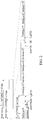
- FIG. 1 is a schematic diagram of a frame structure in related LTE/LTE-A FDD systems. As shown in FIG. 1 , a radio frame of 10ms consists of twenty slots numbered 0 ⁇ 19, each having a length of 0.5ms, slots 2i and 2 i +1 forming a subframe i with a length of 1ms.
- FIG. 2 is a schematic diagram of a frame structure in related LTE/LTE-A TDD systems. As shown in FIG.
- a radio frame of 10ms consists of two half frames each having a length of 5ms, a half frame includes 5 subframes each having a length of 1ms, and a subframe i is defined as 2 slots 2i and 2 i +1 each having a length of 0.5ms.
- one slot contains seven symbols each having a length of 66.7 ⁇ m, wherein the CP length of the first symbol is 5.21 ⁇ s, and the length of each of the remaining 6 symbols is 4.69 ⁇ s; for extended cyclic prefix, one slot contains six symbols, the CP length of each of which is 16.67 ⁇ s.
- Table 1 The supported uplink and downlink configuration is shown as in Table 1.
- Table 1 uplink and downlink configuration table Uplink - downlink configuration Downlink - uplink switching point period Subframe number 0 1 2 3 4 5 6 7 8 9 0 5 ms D S U U U D S U U U 1 5 ms D S U U D D S U U D 2 5 ms D S U D D D S U D D 3 10 ms D S U U U D D D D D D 4 10 ms D S U U D D D D D D D 5 10 ms D S U D D D D D D D D D 6 5 ms D S U U U U D S U U U D S U U D
- D represents a subframe dedicated to downlink transmission
- U represents a subframe dedicated to uplink transmission
- S represents a special subframe which contains three portions, Downlink Pilot Time Slot (DwPTS), Guard Period (GP) and Uplink Pilot Time Slot (UpPTS).
- DwPTS Downlink Pilot Time Slot
- GP Guard Period
- UpPTS Uplink Pilot Time Slot
- an HARQ process refers to that when a sending end needs to transmit data, a receiving end allocates information required in transmission, such as frequency domain resources, packet information, etc., to the sending end through downlink signaling.
- the sending end sends data according to the information while storing the data into its own buffer for retransmission.
- the receiving end detects the data after receiving the data, and sends an acknowledgement (ACK) to the sending end if the data are received correctly.
- ACK acknowledgement
- the sending end clears the buffer memory, which is used in this transmission, after receiving the ACK, and ends this transmission. If the data are not received correctly, then a non-acknowledgement (NACK) is sent to the sending end and packets which are not received correctly are stored into the buffer memory of the receiving end.
- NACK non-acknowledgement
- the sending end After the sending end has received the NACK information, it extracts the data from its own buffer memory and retransmits the data in a specific packet format in corresponding subframes and corresponding frequent domain positions. The retransmitted packets, after being received by the receiving end, are combined with the packets which are not received correctly and are detected once more. The above process is repeated until the data are received correctly or a retransmission times exceeds the maximum transmission times threshold.
- UE detects the PDCCH on subframe n and resolves the PDSCH of the current subframe according to information of the PDCCH.
- UE detects PDSCH transmission on subframe n or indicates the PDCCH of the downlink SPS release and transmits the corresponding HARQ-ACK response on subframe n+4.
- UE detects PDSCH transmission on subframe n-k or indicates the PDCCH of the downlink SPS release and transmits the corresponding HARQ-ACK response on uplink subframe n, wherein k belongs to K, values of which are as shown in table 2.
- Table 2 values of K in different uplink and downlink configurations
- Uplink - downlink configuration Subframe number n 0 1 2 3 4 5 6 7 8 9 0 - - 6 - 4 - - 6 - 4 1 - - 7, 6 4 - - - 7, 6 4 - 2 - - 8, 7, 4, 6 - - - - 8, 7, 4, 6 - - 3 - - 7, 6, 11 6, 5 5, 4 - - - - - 4 - 12, 8, 7, 11 6, 5, 4, 7 - - - - - - 5 - - 13, 12, 9, 8, 7, 5, 4, 11, 6 - - - - - - - - 6 - - 7 7 5 - - 7 7 -
- the UE will feed back the ACK/NACK response information of 1 bit when the PDSCH contains only one transmission block, and the UE will feed back the ACK/NACK response information of 2 bits when the PDSCH contains two transmission blocks, and the UE will send the ACK/NACK response information of 1/2 bit using a PUCCH format 1a/1b.
- FDD Frequency Division Duplex
- the ACK/NACK response information corresponding to a plurality of downlink subframes will be sent on the PUCCH of one uplink subframe, wherein a set of downlink subframes corresponding to the uplink subframe form a "bundling window".
- bundling method the key idea of which is to perform logical AND operation on the ACK/NACK response information, which is required to be fed back in the uplink subframe, of a transmission block corresponding to each of the downlink subframes.
- UE will feed back the ACK/NACK response information of 2 bits, and if there is only one transmission block in each of the subframes, UE will feed back the ACK/NACK response information of 1 bit, and the UE will send the ACK/NACK response information of 1/2 bit using the PUCCH format 1a/1b.
- the other method is multiplexing with channel selection method, the key idea of which is to use different PUCCHs and different modulation symbols on the channels to represent different feedback states of the downlink subframe, which is required to be fed back in the uplink subframe.
- logical AND operation spatial bundling
- channels selection will be performed, and the UE will send the ACK/NACK response information using the format 1b with channel selection.
- the most obvious advantage of the LTE-A system over the LTE system is that carrier aggregation is introduced in the LTE-A system, i.e., bandwidths of the LTE system are aggregated to obtain a greater bandwidth.
- the aggregated carrier is called as a component carrier (CC), or is called as a serving cell.
- CC component carrier
- PCC/PCell Primary Component Carrier/Cell
- SCC/SCell Secondary Component Carrier/Cell
- PUCCH format 1b with channel selection two sending methods are defined, PUCCH format 1b with channel selection and PUCCH format 3.
- the UE will send the HARQ-ACK using the PUCCH format 1b with channel selection when configuring the plurality of serving cells; if the UE can support aggregation of more than 2 serving cells, then when the UE configures the plurality of serving cells, a base station will further configure the UE through high layer signaling to determine whether the UE sends the HARQ-ACK response information using the PUCCH format 1b with channel selection or the PUCCH format 3.
- the related carrier aggregation technology is applied to only FDD serving cells or TDD serving cells.
- FDD serving cells and TDD serving cells when the FDD serving cells and TDD serving cells are aggregated, how to send uplink control information is one of problems required to be solved urgently. Otherwise, the aggregation of the FDD serving cells and TDD serving cells cannot be achieved.
- the technical problem to be solved by the present invention is to provide a method for sending uplink control information, a user equipment and a base station to solve the problem of sending the uplink control information when FDD serving cells and TDD serving cells are aggregated.
- the present invention provides a method for sending uplink control information, comprising:
- the process in which a UE sending uplink control information in uplink subframes of the FDD serving cell and/or uplink subframes of the TDD serving cell according to a predefined rule is as follows:
- a process of sending the uplink control information is as follows:
- the UE when the HARQ-ACK corresponds to the PDSCH of one serving cell, the UE sends the HARQ-ACK in the determined uplink subframes using a PUCCH format 1a/1b.
- a mapping table used by the PUCCH format 1b with channel selection is selected according to any one of the following rules:
- resources used when the UE sends with the PUCCH format 1a/1b are obtained by the following manners:
- the present invention further discloses a user equipment, comprising:
- the second unit is configured to transmit the uplink control information on Physical Uplink Control Channel (PUCCH) or Physical uplink Shared Channel (PUSCH) corresponding to the determined uplink subframes in which the uplink control information is transmitted; wherein the uplink control information includes one or more of channel state information (CSI), scheduling request (SR) and Hybrid automatic repeat request acknowledgement (HARQ-ACK).
- CSI channel state information
- SR scheduling request
- HARQ-ACK Hybrid automatic repeat request acknowledgement
- the second unit is configured to, when the uplink control information includes the HARQ-ACK, make the FDD serving cell determine the HARQ-ACK which needs to be sent on the PUCCH or PUSCH corresponding to the determined uplink subframes according to a Physical downlink Shared Channel (PDSCH) and HARQ-ACK timing relationship corresponding to the FDD serving cell, and make the TDD serving cell determine the HARQ-ACK which needs to be sent on the PUCCH or PUSCH corresponding to the determined uplink subframes according to a PDSCH and HARQ timing relationship corresponding to the TDD serving cell; or make the FDD serving cell determine the HARQ-ACK which needs to be sent on the PUCCH or PUSCH corresponding to the determined uplink subframes according to the PDSCH and HARQ-ACK timing relationship corresponding to the FDD serving cell, and make the TDD serving cell determine the HARQ-ACK which needs to be sent on the PUCCH or PUSCH corresponding to the determined uplink uplink subframes according to the
- the second unit is configured to send the HARQ-ACK in the determined uplink subframes using a PUCCH format 1a/1b when the HARQ-ACK corresponds to the PDSCH of one serving cell.
- the second unit is configured to select a mapping table used by the PUCCH format 1b with channel selection according to any one of the following rules when the HARQ-ACK is sent on the PUCCH corresponding to the determined uplink subframes and a configured sending manner is PUCCH format 1b with channel selection:
- the second unit is configured to, when the HARQ-ACK is sent on the PUCCH corresponding to the determined uplink subframes and the configured sending manner is PUCCH format 3, send the HARQ-ACK using the PUCCH format 1a/1b when the HARQ-ACK corresponds to the PDSCH of one serving cell; and send the HARQ-ACK using the PUCCH format 3 of the existing TDD system when the HARQ-ACK corresponds to the PDSCH of a plurality of serving cells.
- the second unit is configured to, when the HARQ-ACK corresponds to the PDSCH of one serving cell and the serving cell is not the primary serving cell, obtain resources used when sending with the PUCCH format 1a/1b by the following manners:
- the present invention further discloses a base station, comprising:
- the technical scheme of the present application can solve the problem of sending the uplink control information when FDD serving cells and TDD serving cells are aggregated.
- various predefined rules may be chosen according to the type of the UE.
- the rule when the UE has no ability of uplink carrier aggregation, the rule is that the uplink control information is transmitted in the uplink subframes of the primary serving cell. Or when the UE has the ability of uplink carrier aggregation, the rule is that signaling indicates that the uplink control information is sent in the uplink subframes of the FDD serving cell or the uplink subframes of the TDD serving cell.
- the signaling configures various predefined rules.
- the used rules configured by the signaling are: a primary serving cell is the TDD serving cell, subframes N have both the uplink subframes of the FDD serving cell and the uplink subframes of the TDD serving cell, and when there is uplink control information to be sent in the subframes N, the UE sends the uplink control information in the uplink subframes of the TDD serving cell; a primary serving cell is the TDD serving cell, subframes N have only the uplink subframes of the FDD serving cell, and when there is uplink control information to be sent in the subframes N, the UE sends the uplink control information in the uplink subframes of the FDD serving cell; a primary serving cell is the TDD serving cell, subframes N have only the uplink subframes of the TDD serving cell, and when there is uplink control information to be sent in the subframes N, the UE sends the uplink control information in the uplink subframes of the TDD serving cell; and when a primary serving cell is the
- the process in which the UE sends the uplink control information in the uplink subframes of the FDD serving cell and/or the uplink subframes of the TDD serving cell according to the predefined rule may refer to the following operations:
- the process in which the uplink control information is sent is as follows:
- the UE sends the HARQ-ACK in the determined uplink subframes using a PUCCH format 1a/1b.
- a mapping table used by the PUCCH format 1b with channel selection is selected according to any one of the following rules:
- the UE When the UE sends the HARQ-ACK on the PUCCH corresponding to the determined uplink subframes and the configured sending manner is PUCCH format 3, the UE selects different sending manners according to different situations:
- resources used when the UE sends with the PUCCH format 1a/1b are obtained by the following manners:
- the TDD serving cell is the primary serving cell, the TDD serving cell determines the HARQ-ACK which needs to be sent according to the PDSCH and HARQ timing relationship corresponding to the TDD serving cell, and the FDD serving cell determines the HARQ-ACK which needs to be sent according to the PDSCH and HARQ timing relationship corresponding to the FDD serving cell.
- the PUCCH corresponding to the HARQ-ACK is sent in the uplink subframes where the TDD serving cell is located; and when the subframes N have only uplink subframes of the FDD serving cell, the PUCCH corresponding to the HARQ-ACK is sent in the uplink subframes where the FDD serving cell is located.
- the TDD serving cell is the primary serving cell, the TDD serving cell determines the HARQ-ACK which needs to be sent according to the PDSCH and HARQ timing relationship corresponding to the FDD serving cell, and the FDD serving cell determines the HARQ-ACK which needs to be sent according to the PDSCH and HARQ timing relationship corresponding to the FDD serving cell.
- the PUCCH corresponding to the HARQ-ACK is sent in the uplink subframes where the TDD serving cell is located; and when the subframes N have only uplink subframes of the FDD serving cell, the PUCCH corresponding to the HARQ-ACK is sent in the uplink subframes where the FDD serving cell is located.
- the FDD serving cell is the primary serving cell, the TDD serving cell determines the HARQ-ACK which needs to be sent according to the PDSCH and HARQ timing relationship corresponding to the TDD serving cell, and the FDD serving cell determines the HARQ-ACK which needs to be sent according to the PDSCH and HARQ timing relationship corresponding to the FDD serving cell, and the PUCCH corresponding to the HARQ-ACK is sent in the uplink subframes where the FDD serving cell is located.
- the FDD serving cell is the primary serving cell, the TDD serving cell determines the HARQ-ACK which needs to be sent according to the PDSCH and HARQ timing relationship corresponding to the FDD serving cell, and the FDD serving cell determines the HARQ-ACK which needs to be sent according to the PDSCH and HARQ timing relationship corresponding to the FDD serving cell, and the PUCCH corresponding to the HARQ-ACK is sent in the uplink subframes where the FDD serving cell is located.
- the FDD serving cell is the primary serving cell, the FDD serving cell schedules the TDD serving cell by cross-carrier, the TDD serving cell determines the HARQ-ACK which needs to be sent according to the PDSCH and HARQ timing relationship corresponding to the FDD serving cell, and the FDD serving cell determines the HARQ-ACK which needs to be sent according to the PDSCH and HARQ timing relationship corresponding to the FDD serving cell, and the PUCCH corresponding to the HARQ-ACK is sent in the uplink subframes where the FDD serving cell is located.
- the FDD serving cell and TDD serving cell configuration 0 are aggregated. Assume that SR is required to be sent in subframe #2 and CSI is required to be sent in subframe #5.
- SR is sent on the PUCCH corresponding to uplink subframe #2 of the TDD serving cell and CSI is sent on the PUCCH or PISCH corresponding to uplink subframe #5 of the FDD serving cell.
- SR is sent on the PUCCH corresponding to uplink subframe #2 of the FDD serving cell and CSI is sent on the PUCCH or PISCH corresponding to uplink subframe #5 of the FDD serving cell.
- signaling configures SR to be sent in uplink subframes of the FDD serving cell and CSI also to be sent in the FDD serving cell
- the SR is sent on the PUCCH corresponding to uplink subframe #2 of the FDD serving cell
- the CSI is sent on the PUCCH or PISCH corresponding to uplink subframe #5 of the FDD serving cell.
- the TDD serving cell is the primary serving cell, according to the PDSCH and HARQ-ACK timing relationship determined in specific example 2 in the first embodiment and the uplink subframes sent on the PUCCH corresponding to the HARQ-ACK, when the sending manner is configured as format 1b with channel selection, when a mapping table is selected according to rule 1, i.e., the mapping table corresponding to the TDD system is used, in the existing TDD system, mapping tables in which the number of downlink subframes in a binding window is less than or equal to 2 are shown as table 3.
- the mapping tables corresponding to the existing TDD system are shown as table 3, table 4 and table 5; the mapping tables corresponding to the existing FDD system are shown as table 14, table 15 and table 16.
- the mapping tables corresponding to the existing TDD system are shown as table 1, table 2, table 3, table 4 and table 5; the mapping tables corresponding to the existing FDD system are shown as table 14, table 15 and table 16.
- the implementation way is the same as that in the specific example 1 and will not be repeated herein.
- the TDD serving cell is the primary serving cell, according to the PDSCH and HARQ-ACK timing relationship and the uplink subframes sent on the PUCCH corresponding to the HARQ-ACK determined in specific example 5 in the first embodiment, when the sending manner is configured as the format 1b with channel selection, a mapping table is selected according to rule 1, i.e., the mapping table corresponding to the TDD system is used.
- uplink subframes #4, #5, #6, #7, #8 and #9 of radio frame #n and uplink subframes #0 and #1 of radio frame #n+1 the implementation way is the same as that in the specific example 5 in the first embodiment and will not be repeated herein.
- the format 1b with channel selection is implemented according to table 7, and the correspondence relationship of HARQ(j) is as shown in table 17.
- the TDD serving cell is the primary serving cell, according to the PDSCH and HARQ-ACK timing relationship and the uplink subframes sent on the PUCCH corresponding to the HARQ-ACK determined in the specific example 5 in the first embodiment, when the sending manner is PUCCH format 3,
- the HARQ-ACK corresponds to the PDSCH of only one serving cell, and is sent using the PUCCH format 1a/1b, If downlink subframe #0 in the FDD serving cell in radio frame #0 is scheduled through cross-carrier by the TDD serving cell, then the resources corresponding to the format 1a/1b are obtained in an implicit mapping manner, otherwise, they are obtained by configuring through a high layer, or a set of resources is configured by a high layer, and TPC corresponding to CCI indicates the resources specifically used, or a set of resources is configured by a high layer, and ARO corresponding to the E-PDCCH indicates the resources specifically used; the processing manner for uplink subframes #5, #6, #7, and #9 of radio frame #n and uplink subframes #0 and #1 of radio frame #n+1 is the same as that for uplink subframe #4 of radio frame #n and will not be repeated herein; For uplink subframes #2 and #3 of radio frame #n+1, the HARQ
- the second embodiment provides a user equipment which, as shown in FIG. 10 , can implement transmission of uplink control information in the first embodiment described above and include at least two units, a first unit and a second unit.
- the first unit determines uplink subframes in which uplink control information is transmitted to be uplink subframes of the FDD serving cell and/or uplink subframes of the TDD serving cell according to a predefined rule when the FDD serving cell and the TDD serving cell are aggregated.
- the second unit sends the uplink control information in the determined uplink subframes in which the uplink control information is transmitted.
- the predefined rule includes one or more of the following rules:
- the second unit transmits the uplink control information on the PUCCH or PUSCH corresponding to the determined uplink subframes in which the uplink control information is transmitted.
- the uplink control information includes one or more of CSI, SR and HARQ-ACK.
- the second unit makes the FDD serving cell determine the HARQ-ACK which needs to be sent on the PUCCH or PUSCH corresponding to the determined uplink subframes according to the PDSCH and HARQ-ACK timing relationship corresponding to the FDD serving cell, and makes the TDD serving cell determine the HARQ-ACK which needs to be sent on the PUCCH or PUSCH corresponding to the determined uplink subframes according to the PDSCH and HARQ timing relationship corresponding to the TDD serving cell; or the second unit makes the FDD serving cell determine the HARQ-ACK which needs to be sent on the PUCCH or PUSCH corresponding to the determined uplink subframes according to the PDSCH and HARQ-ACK timing relationship corresponding to the FDD serving cell, and makes the TDD serving cell determine the HARQ-ACK which needs to be sent on the PUCCH or PUSCH corresponding to the determined uplink subframes according to the HARQ-ACK timing relationship corresponding to the FDD serving cell
- the second unit can send the HARQ-ACK in the determined uplink subframes using a PUCCH format 1a/1b when the HARQ-ACK corresponds to the PDSCH of one serving cell.
- the second unit selects a mapping table used by the PUCCH format 1b with channel selection according to any one of the following rules when the HARQ-ACK is sent on the PUCCH corresponding to the determined uplink subframes and a configured sending manner is PUCCH format 1b with channel selection:
- the second unit selects different sending manners according to different cases.
- the second unit sends the HARQ-ACK using the PUCCH format 1a/1b when the HARQ-ACK corresponds to the PDSCH of one serving cell.
- the second unit sends the HARQ-ACK using the PUCCH format 3 of the existing TDD system when the HARQ-ACK corresponds to the PDSCH of a plurality of serving cells.
- the second unit obtains resources used when sending with the PUCCH format 1a/1b by the following manners:
- the present embodiment provides a base station comprising two units, a first unit and a second unit.
- the first unit determines uplink subframes in which uplink control information is transmitted to be uplink subframes of the FDD serving cell and/or uplink subframes of the TDD serving cell according to a predefined rule when the FDD serving cell and the TDD serving cell are aggregated.
- the second unit receives the uplink control information in the determined uplink subframes in which uplink control information is transmitted.
- the predefined rule includes one or more of the following rules:
- the second unit receives the uplink control information on the PUCCH or PUSCH corresponding to the determined uplink subframes in which the uplink control information is transmitted.
- the uplink control information includes one or more of CSI, SR and HARQ-ACK.
- the second unit makes the FDD serving cell determine the HARQ-ACK which needs to be sent on the PUCCH or PUSCH corresponding to the determined uplink subframes according to the PDSCH and HARQ-ACK timing relationship corresponding to the FDD serving cell, and makes the TDD serving cell determine the HARQ-ACK which needs to be sent on the PUCCH or PUSCH corresponding to the determined uplink subframes according to the PDSCH and HARQ timing relationship corresponding to the TDD serving cell; or the second unit makes the FDD serving cell determine the HARQ-ACK which needs to be sent on the PUCCH or PUSCH corresponding to the determined uplink subframes according to the PDSCH and HARQ-ACK timing relationship corresponding to the FDD serving cell, and makes the TDD serving cell determine the HARQ-ACK which needs to be sent on the PUCCH or PUSCH corresponding to the determined uplink subframes according to the HARQ-ACK timing relationship corresponding to the FDD serving cell
- the second unit receives the HARQ-ACK in the determined uplink subframes using a PUCCH format 1a/1b when the HARQ-ACK corresponds to the PDSCH of one serving cell.
- the second unit selects a mapping table used by the PUCCH format 1b with channel selection according to any one of the following rules when the HARQ-ACK is received on the PUCCH corresponding to the determined uplink subframes and the configured transmitting manner is PUCCH format 1b with channel selection:
- the second unit obtains resources used when receiving with the PUCCH format 1a/1b by the following manners:
- the technical scheme of the present application can solve the problem of sending uplink control information when FDD serving cells and TDD serving cells are aggregated.
Abstract
Description
- The present invention relates to wireless communication technology, and more particularly, to a method for sending uplink control information, a user equipment and a base station.
- Radio frames in Long Term Evolution (LTE) systems and LTE-Advanced (LTE-A) systems include frame structures in a Frequency Division Duplex (FDD) mode and a Time Division Duplex (TDD) mode.
FIG. 1 is a schematic diagram of a frame structure in related LTE/LTE-A FDD systems. As shown inFIG. 1 , a radio frame of 10ms consists of twenty slots numbered 0∼19, each having a length of 0.5ms, slots 2i and 2i+1 forming a subframe i with a length of 1ms.FIG. 2 is a schematic diagram of a frame structure in related LTE/LTE-A TDD systems. As shown inFIG. 2 , a radio frame of 10ms consists of two half frames each having a length of 5ms, a half frame includes 5 subframes each having a length of 1ms, and a subframe i is defined as 2 slots 2i and 2i+1 each having a length of 0.5ms. - In the two frame structures described above, for normal cyclic prefix (CP), one slot contains seven symbols each having a length of 66.7 µm, wherein the CP length of the first symbol is 5.21 µs, and the length of each of the remaining 6 symbols is 4.69 µs; for extended cyclic prefix, one slot contains six symbols, the CP length of each of which is 16.67 µs. The supported uplink and downlink configuration is shown as in Table 1.
Table 1: uplink and downlink configuration table Uplink - downlink configuration Downlink - uplink switching point period Subframe number 0 1 2 3 4 5 6 7 8 9 0 5 ms D S U U U D S U U U 1 5 ms D S U U D D S U U D 2 5 ms D S U D D D S U D D 3 10 ms D S U U U D D D D D 4 10 ms D S U U D D D D D D 5 10 ms D S U D D D D D D D 6 5 ms D S U U U D S U U D - For each subframe in one radio frame, "D" represents a subframe dedicated to downlink transmission, "U" represents a subframe dedicated to uplink transmission, "S" represents a special subframe which contains three portions, Downlink Pilot Time Slot (DwPTS), Guard Period (GP) and Uplink Pilot Time Slot (UpPTS).
- In an LTE system, an HARQ process refers to that when a sending end needs to transmit data, a receiving end allocates information required in transmission, such as frequency domain resources, packet information, etc., to the sending end through downlink signaling. The sending end sends data according to the information while storing the data into its own buffer for retransmission. The receiving end detects the data after receiving the data, and sends an acknowledgement (ACK) to the sending end if the data are received correctly. The sending end clears the buffer memory, which is used in this transmission, after receiving the ACK, and ends this transmission. If the data are not received correctly, then a non-acknowledgement (NACK) is sent to the sending end and packets which are not received correctly are stored into the buffer memory of the receiving end. After the sending end has received the NACK information, it extracts the data from its own buffer memory and retransmits the data in a specific packet format in corresponding subframes and corresponding frequent domain positions. The retransmitted packets, after being received by the receiving end, are combined with the packets which are not received correctly and are detected once more. The above process is repeated until the data are received correctly or a retransmission times exceeds the maximum transmission times threshold.
- In an LTE/LTE-A system, there is following specification regarding to PDSCH scheduling in downlink HARQ, i.e., regarding to scheduling of downlink HARQ: UE detects the PDCCH on subframe n and resolves the PDSCH of the current subframe according to information of the PDCCH.
- In an LTE/LTE-A FDD system, there is the following timing rule regarding to the PUCCH corresponding to the HARQ-ACK of the PDSCH sent in the downlink HARQ, i.e., the following specification regarding to a timing relationship of the downlink HARQ: UE detects PDSCH transmission on subframe n or indicates the PDCCH of the downlink SPS release and transmits the corresponding HARQ-ACK response on subframe n+4. In an LTE/LTE-A TDD system, there is the following specification regarding to a timing relationship of the downlink HARQ: UE detects PDSCH transmission on subframe n-k or indicates the PDCCH of the downlink SPS release and transmits the corresponding HARQ-ACK response on uplink subframe n, wherein k belongs to K, values of which are as shown in table 2.
Table 2: values of K in different uplink and downlink configurations Uplink - downlink configuration Subframe number n 0 1 2 3 4 5 6 7 8 9 0 - - 6 - 4 - - 6 - 4 1 - - 7, 6 4 - - - 7, 6 4 - 2 - - 8, 7, 4, 6 - - - - 8, 7, 4, 6 - - 3 - - 7, 6, 11 6, 5 5, 4 - - - - - 4 - - 12, 8, 7, 11 6, 5, 4, 7 - - - - - - 5 - - 13, 12, 9, 8, 7, 5, 4, 11, 6 - - - - - - - 6 - - 7 7 5 - - 7 7 - - In an LTE system, for example a Frequency Division Duplex (FDD) system, because of a one-to-one correspondence between uplink and downlink subframes, the UE will feed back the ACK/NACK response information of 1 bit when the PDSCH contains only one transmission block, and the UE will feed back the ACK/NACK response information of 2 bits when the PDSCH contains two transmission blocks, and the UE will send the ACK/NACK response information of 1/2 bit using a PUCCH format 1a/1b. In a Time Division Duplex (FDD) system, because there is no one-to-one correspondence between uplink and downlink subframes, the ACK/NACK response information corresponding to a plurality of downlink subframes will be sent on the PUCCH of one uplink subframe, wherein a set of downlink subframes corresponding to the uplink subframe form a "bundling window". There are two methods for sending the ACK/NACK response information. One is bundling method, the key idea of which is to perform logical AND operation on the ACK/NACK response information, which is required to be fed back in the uplink subframe, of a transmission block corresponding to each of the downlink subframes. If there are 2 transmission blocks in one downlink subframe, UE will feed back the ACK/NACK response information of 2 bits, and if there is only one transmission block in each of the subframes, UE will feed back the ACK/NACK response information of 1 bit, and the UE will send the ACK/NACK response information of 1/2 bit using the PUCCH format 1a/1b. The other method is multiplexing with channel selection method, the key idea of which is to use different PUCCHs and different modulation symbols on the channels to represent different feedback states of the downlink subframe, which is required to be fed back in the uplink subframe. If there are a plurality of transmission blocks in the downlink subframes, logical AND operation (spatial bundling) will be performed on the ACK/NACK information fed back by the plurality of transmission blocks of the downlink subframes and then channels selection will be performed, and the UE will send the ACK/NACK response information using the format 1b with channel selection.
- The most obvious advantage of the LTE-A system over the LTE system is that carrier aggregation is introduced in the LTE-A system, i.e., bandwidths of the LTE system are aggregated to obtain a greater bandwidth. In the system where the carrier aggregation is introduced, the aggregated carrier is called as a component carrier (CC), or is called as a serving cell. Meanwhile, concepts of Primary Component Carrier/Cell (PCC/PCell) and Secondary Component Carrier/Cell (SCC/SCell) are proposed. A primary serving cell and secondary serving cell are at least included in a system where the carrier aggregation is performed, wherein the primary serving cell is always in an activation state and the PUCCH is defined to be transmitted only on the Pcell.
- In an LTE-A carrier aggregation system, when the HARQ-ACK response information is sent on the PUCCH, two sending methods are defined, PUCCH format 1b with channel selection and
PUCCH format 3. For a UE which configures a plurality of serving cells, if the UE can support aggregation of only 2 serving cells at most, then the UE will send the HARQ-ACK using the PUCCH format 1b with channel selection when configuring the plurality of serving cells; if the UE can support aggregation of more than 2 serving cells, then when the UE configures the plurality of serving cells, a base station will further configure the UE through high layer signaling to determine whether the UE sends the HARQ-ACK response information using the PUCCH format 1b with channel selection or thePUCCH format 3. - The related carrier aggregation technology is applied to only FDD serving cells or TDD serving cells. In subsequent versions, considering the FDD serving cells and TDD serving cells, when the FDD serving cells and TDD serving cells are aggregated, how to send uplink control information is one of problems required to be solved urgently. Otherwise, the aggregation of the FDD serving cells and TDD serving cells cannot be achieved.
- The technical problem to be solved by the present invention is to provide a method for sending uplink control information, a user equipment and a base station to solve the problem of sending the uplink control information when FDD serving cells and TDD serving cells are aggregated.
- In order to solve the above technical problem, the present invention provides a method for sending uplink control information, comprising:
- when a Frequency Division Duplex (FDD) serving cell and a Time Division Duplex (TDD) serving cell are aggregated, a user equipment (UE) sending uplink control information in uplink subframes of the FDD serving cell and/or uplink subframes of the TDD serving cell according to a predefined rule;
- wherein the predefined rule includes one or more of the following rules:
- a primary serving cell is the TDD serving cell, subframes N have both the uplink subframes of the FDD serving cell and the uplink subframes of the TDD serving cell, and when there is uplink control information to be sent in the subframes N, the UE sends the uplink control information in the uplink subframes of the TDD serving cell;
- a primary serving cell is the TDD serving cell, subframes N have only the uplink subframes of the FDD serving cell, and when there is uplink control information to be sent in the subframes N, the UE sends the uplink control information in the uplink subframes of the FDD serving cell;
- a primary serving cell is the TDD serving cell, subframes N have only the uplink subframes of the TDD serving cell, and when there is uplink control information to be sent in the subframes N, the UE sends the uplink control information in the uplink subframes of the TDD serving cell;
- when a primary serving cell is the FDD serving cell, the UE sends the uplink control information in the uplink subframes of the FDD serving cell;
- signaling indicates that the uplink control information is sent in the uplink subframes of the FDD serving cell or the uplink subframes of the TDD serving cell; and
- the uplink control information is transmitted in the uplink subframes of the primary serving cell.
- Alternatively, in the method described above, the process in which a UE sending uplink control information in uplink subframes of the FDD serving cell and/or uplink subframes of the TDD serving cell according to a predefined rule is as follows:
- the UE determines the uplink subframes in which the uplink control information is transmitted to be the uplink subframes of the FDD serving cell and/or the uplink subframes of the TDD serving cell according to the predefined rule, and transmits the uplink control information on Physical Uplink Control Channel (PUCCH) or Physical uplink Shared Channel (PUSCH) corresponding to the determined uplink subframes;
- Alternatively, in the method described above, when the UE sends the HARQ-ACK on the PUCCH or PUSCH corresponding to the determined uplink subframes, a process of sending the uplink control information is as follows:
- the UE makes the FDD serving cell determine the HARQ-ACK which needs to be sent on the PUCCH or PUSCH corresponding to the determined uplink subframes according to a Physical downlink Shared Channel (PDSCH) and HARQ-ACK timing relationship corresponding to the FDD serving cell, and the UE makes the TDD serving cell determine the HARQ-ACK which needs to be sent on the PUCCH or PUSCH corresponding to the determined uplink subframes according to a PDSCH and HARQ timing relationship corresponding to the TDD serving cell; or
- the UE makes the FDD serving cell determine the HARQ-ACK which needs to be sent on the PUCCH or PUSCH corresponding to the determined uplink subframes according to the PDSCH and HARQ-ACK timing relationship corresponding to the FDD serving cell, and the UE makes the TDD serving cell determine the HARQ-ACK which needs to be sent on the PUCCH or PUSCH corresponding to the determined uplink subframes according to the HARQ-ACK timing relationship corresponding to the FDD serving cell; or
- when the FDD serving cell is the primary serving cell, the UE makes both the FDD serving cell and the TDD serving cell determine the HARQ-ACK which needs to be sent on the PUCCH or PUSCH corresponding to the determined uplink subframes according to the PDSCH and HARQ-ACK timing relationship corresponding to the FDD serving cell, and when the TDD serving cell is the primary serving cell, the UE makes the FDD serving cell and the TDD serving cell respectively determine the HARQ-ACK which needs to be sent on the PUCCH or PUSCH corresponding to the determined uplink subframes according to the PDSCH and HARQ-ACK timing relationships corresponding to the respective serving cells.
- Alternatively, in the method described above, when the HARQ-ACK corresponds to the PDSCH of one serving cell, the UE sends the HARQ-ACK in the determined uplink subframes using a PUCCH format 1a/1b.
- Alternatively, in the method described above, when the UE sends the HARQ-ACK on the PUCCH corresponding to the determined uplink subframes and a configured sending manner is PUCCH format 1b with channel selection, a mapping table used by the PUCCH format 1b with channel selection is selected according to any one of the following rules:
- a mapping table corresponding to the TDD system is used;
- a corresponding mapping table is selected according to M, when M>=2, a mapping table corresponding to the existing TDD system is used, and when M=1, a mapping table corresponding to the existing FDD system is used;
- a corresponding mapping table is selected according to the value of M and the primary serving cell, when M>=2, the mapping table corresponding to the existing TDD system is used, and when M=1, in a case that the FDD serving cell is the primary cell, the mapping table corresponding to the existing FDD system is used, and in a case that the TDD serving cell is the primary cell, the mapping table corresponding to the existing TDD system is used.
- Alternatively, in the method described above, the M is max{MTDD, MFDD}, MFDD is a number of downlink subframes within a binding window determined by the FDD serving cell according to the timing relationship, and when MFDD=1, MTDD is a number of downlink subframes within a binding window determined by the TDD serving cell according to the timing relationship; when the HARQ-ACK corresponds only the PDSCH of the FDD serving cell, MTDD=0.
- Alternatively, in the method described above, when the UE sends the HARQ-ACK on the PUCCH corresponding to the determined uplink subframes and the configured sending manner is PUCCH format 3:
- when the HARQ-ACK corresponds to the PDSCH of one serving cell, the UE sends the HARQ-ACK using the PUCCH format 1a/1b; and
- when the HARQ-ACK corresponds to the PDSCH of a plurality of serving cells, the UE sends the HARQ-ACK using the
PUCCH format 3 of the existing TDD system. - Alternatively, in the method described above, when the HARQ-ACK corresponds to the PDSCH of one serving cell and the serving cell is not the primary serving cell, resources used when the UE sends with the PUCCH format 1a/1b are obtained by the following manners:
- when the PDSCH of the serving cell corresponding to the HARQ-ADK is scheduled through cross-carrier by the primary serving cell, the PUCCH resources used when sending with the PUCCH format 1a/1b are obtained in an implicit mapping manner; and
- when the PDSCH of the serving cell corresponding to the HARQ-ADK is not scheduled through cross-carrier by the primary serving cell, the PUCCH resources used when sending with the PUCCH format 1a/1b are obtained in any one of the following manners:
- configuring through high layer signaling; or
- a set of resources is configured by a high layer, and transmission power control (TPC) corresponding to downlink control information (CCI) indicates the resources specifically used; or
- a set of resources is configured by a high layer, and acknowledgement/non-acknowledgement (ACK/NACK) resource offset (ARO) corresponding to Enhanced Physical Downlink Control Channel (E-PDCCH) indicates the resources specifically used.
- The present invention further discloses a user equipment, comprising:
- a first unit, configured to determine uplink subframes in which uplink control information is transmitted to be uplink subframes of a Frequency Division Duplex (FDD) serving cell and/or uplink subframes of a Time Division Duplex (TDD) serving cell according to a predefined rule when the FDD serving cell and the TDD serving cell are aggregated; and
- a second unit, configured to send the uplink control information in the determined uplink subframes in which the uplink control information is transmitted;
- wherein the predefined rule includes one or more of the following rules:
- a primary serving cell is the TDD serving cell, subframes N have both the uplink subframes of the FDD serving cell and the uplink subframes of the TDD serving cell, and when there is uplink control information to be sent in the subframes N, the UE sends the uplink control information in the uplink subframes of the TDD serving cell;
- a primary serving cell is the TDD serving cell, subframes N have only the uplink subframes of the FDD serving cell, and when there is uplink control information to be sent in the subframes N, the UE sends the uplink control information in the uplink subframes of the FDD serving cell;
- a primary serving cell is the TDD serving cell, subframes N have only the uplink subframes of the TDD serving cell, and when there is uplink control information to be sent in the subframes N, the UE sends the uplink control information in the uplink subframes of the TDD serving cell;
- when a primary serving cell is the FDD serving cell, the UE sends the uplink control information in the uplink subframes of the FDD serving cell;
- signaling indicates that the uplink control information is sent in the uplink subframes of the FDD serving cell or the uplink subframes of the TDD serving cell; and
- the uplink control information is transmitted in the uplink subframes of the primary serving cell.
- Alternatively, in the user equipment described above, the second unit is configured to transmit the uplink control information on Physical Uplink Control Channel (PUCCH) or Physical uplink Shared Channel (PUSCH) corresponding to the determined uplink subframes in which the uplink control information is transmitted;
wherein the uplink control information includes one or more of channel state information (CSI), scheduling request (SR) and Hybrid automatic repeat request acknowledgement (HARQ-ACK). - Alternatively, in the user equipment described above, the second unit is configured to, when the uplink control information includes the HARQ-ACK,
make the FDD serving cell determine the HARQ-ACK which needs to be sent on the PUCCH or PUSCH corresponding to the determined uplink subframes according to a Physical downlink Shared Channel (PDSCH) and HARQ-ACK timing relationship corresponding to the FDD serving cell, and make the TDD serving cell determine the HARQ-ACK which needs to be sent on the PUCCH or PUSCH corresponding to the determined uplink subframes according to a PDSCH and HARQ timing relationship corresponding to the TDD serving cell; or
make the FDD serving cell determine the HARQ-ACK which needs to be sent on the PUCCH or PUSCH corresponding to the determined uplink subframes according to the PDSCH and HARQ-ACK timing relationship corresponding to the FDD serving cell, and make the TDD serving cell determine the HARQ-ACK which needs to be sent on the PUCCH or PUSCH corresponding to the determined uplink subframes according to the HARQ-ACK timing relationship corresponding to the FDD serving cell; or
make both the FDD serving cell and the TDD serving cell determine the HARQ-ACK which needs to be sent on the PUCCH or PUSCH corresponding to the determined uplink subframes according to the PDSCH and HARQ-ACK timing relationship corresponding to the FDD serving cell when the FDD serving cell is the primary serving cell; and make the FDD serving cell and the TDD serving cell respectively determine the HARQ-ACK which needs to be sent on the PUCCH or PUSCH corresponding to the determined uplink subframes according to the PDSCH and HARQ-ACK timing relationship corresponding to the respective serving cell when the TDD serving cell is the primary serving cell. - Alternatively, in the user equipment described above, the second unit is configured to send the HARQ-ACK in the determined uplink subframes using a PUCCH format 1a/1b when the HARQ-ACK corresponds to the PDSCH of one serving cell.
- Alternatively, in the user equipment described above, the second unit is configured to select a mapping table used by the PUCCH format 1b with channel selection according to any one of the following rules when the HARQ-ACK is sent on the PUCCH corresponding to the determined uplink subframes and a configured sending manner is PUCCH format 1b with channel selection:
- a mapping table corresponding to the TDD system is used;
- a corresponding mapping table is selected according to M, when M>=2, a mapping table corresponding to the existing TDD system is used, and when M=1, a mapping table corresponding to the existing FDD system is used; and
- a corresponding mapping table is selected according to the value of M and the primary serving cell, when M>=2, the mapping table corresponding to the existing TDD system is used, and when M=1, in a case that the FDD serving cell is the primary cell, the mapping table corresponding to the existing FDD system is used, and in a case that the TDD serving cell is the primary cell, the mapping table corresponding to the existing TDD system is used.
- Alternatively, in the user equipment described above, the M is max{MTDD, MFDD}, MFDD is a number of downlink subframes within a binding window determined by the FDD serving cell according to the timing relationship, and when MFDD=1, MTDD is a number of downlink subframes within a binding window determined by the TDD serving cell according to the timing relationship; when the HARQ-ACK corresponds only the PDSCH of the FDD serving cell, MTDD=0.
- Alternatively, in the user equipment described above, the second unit is configured to, when the HARQ-ACK is sent on the PUCCH corresponding to the determined uplink subframes and the configured sending manner is
PUCCH format 3,
send the HARQ-ACK using the PUCCH format 1a/1b when the HARQ-ACK corresponds to the PDSCH of one serving cell; and
send the HARQ-ACK using thePUCCH format 3 of the existing TDD system when the HARQ-ACK corresponds to the PDSCH of a plurality of serving cells. - Alternatively, in the user equipment described above, the second unit is configured to, when the HARQ-ACK corresponds to the PDSCH of one serving cell and the serving cell is not the primary serving cell, obtain resources used when sending with the PUCCH format 1a/1b by the following manners:
- when the PDSCH of the serving cell corresponding to the HARQ-ADK is scheduled through cross-carrier by the primary serving cell, the PUCCH resources used when sending with the PUCCH format 1a/1b are obtained in an implicit mapping manner; and
- when the PDSCH of the serving cell corresponding to the HARQ-ADK is not scheduled through cross-carrier by the primary serving cell, the PUCCH resources used when sending with the PUCCH format 1a/1b are obtained in any one of the following manners:
- configuring through high layer signaling; or
- a set of resources is configured by a high layer, and transmission power control (TPC) corresponding to downlink control information (CCI) indicates the resources specifically used; or
- a set of resources is configured by a high layer, and acknowledgement/non-acknowledgement (ACK/NACK) resource offset (ARO) corresponding to Enhanced Physical Downlink Control Channel (E-PDCCH) indicates the resources specifically used.
- The present invention further discloses a base station, comprising:
- a first unit, configured to determine uplink subframes in which uplink control information is transmitted to be uplink subframes of a Frequency Division Duplex (FDD) serving cell and/or uplink subframes of a Time Division Duplex (TDD) serving cell according to a predefined rule when the FDD serving cell and the TDD serving cell are aggregated; and
- a second unit, configured to receive the uplink control information in the determined uplink subframes in which uplink control information is transmitted;
- a primary serving cell is the TDD serving cell, subframes N have both the uplink subframes of the FDD serving cell and the uplink subframes of the TDD serving cell, and when there is uplink control information to be sent in the subframes N, the uplink control information is received in the uplink subframes of the TDD serving cell;
- a primary serving cell is the TDD serving cell, subframes N have only the uplink subframes of the FDD serving cell, and when there is uplink control information to be sent in the subframes N, the uplink control information is received in the uplink subframes of the FDD serving cell;
- a primary serving cell is the TDD serving cell, subframes N have only the uplink subframes of the TDD serving cell, and when there is uplink control information to be sent in the subframes N, the uplink control information is received in the uplink subframes of the TDD serving cell;
- when a primary serving cell is the FDD serving cell, the uplink control information is received in the uplink subframes of the FDD serving cell;
- signaling indicates that the uplink control information is transmitted in the uplink subframes of the FDD serving cell or the uplink subframes of the TDD serving cell; and
- the uplink control information is transmitted in the uplink subframes of the primary serving cell.
- The technical scheme of the present application can solve the problem of sending the uplink control information when FDD serving cells and TDD serving cells are aggregated.
-
-
FIG. 1 is a schematic diagram of a frame structure in a FDD system in accordance with the related art. -
FIG. 2 is a schematic diagram of a frame structure in a TDD system in accordance with the related art. -
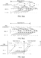
FIG. 3(a) is a schematic diagram of aggregation of a FDD serving cell and a TDD servingcell configuration 0 in accordance with the first example; -
FIG. 3(b) is a schematic diagram of aggregation of a FDD serving cell and a TDD servingcell configuration 0 in accordance with the second example; -
FIG. 3(c) is a schematic diagram of aggregation of a FDD serving cell and a TDD servingcell configuration 0 in accordance with the third example; -
FIG. 4(a) is a schematic diagram of aggregation of a FDD serving cell and a TDD servingcell configuration 1 in accordance with the first example; -
FIG. 4(b) is a schematic diagram of aggregation of a FDD serving cell and a TDD servingcell configuration 1 in accordance with the second example; -
FIG. 4(c) is a schematic diagram of aggregation of a FDD serving cell and a TDD servingcell configuration 1 in accordance with the third example; -
FIG. 5(a) is a schematic diagram of aggregation of a FDD serving cell and a TDD servingcell configuration 2 in accordance with the first example; -
FIG. 5(b) is a schematic diagram of aggregation of a FDD serving cell and a TDD servingcell configuration 2 in accordance with the second example; -
FIG. 5(c) is a schematic diagram of aggregation of a FDD serving cell and a TDD servingcell configuration 2 in accordance with the fourth example; -
FIG. 6(a) is a schematic diagram of aggregation of a FDD serving cell and a TDD servingcell configuration 3 in accordance with the first example; -
FIG. 6(b) is a schematic diagram of aggregation of a FDD serving cell and a TDD servingcell configuration 3 in accordance with the second example; -
FIG. 6(c) is a schematic diagram of aggregation of a FDD serving cell and a TDD servingcell configuration 3 in accordance with the fourth example; -
FIG. 7(a) is a schematic diagram of aggregation of a FDD serving cell and a TDD servingcell configuration 4 in accordance with the first example; -
FIG. 7(b) is a schematic diagram of aggregation of a FDD serving cell and a TDD servingcell configuration 4 in accordance with the second example; -
FIG. 8(a) is a schematic diagram of aggregation of a FDD serving cell and a TDD servingcell configuration 5 in accordance with the first example; -
FIG. 8(b) is a schematic diagram of aggregation of a FDD serving cell and a TDD servingcell configuration 5 in accordance with the second example; -
FIG. 9(a) is a schematic diagram of aggregation of a FDD serving cell and a TDD servingcell configuration 6 in accordance with the first example; -
FIG. 9(b) is a schematic diagram of aggregation of a FDD serving cell and a TDD servingcell configuration 6 in accordance with the second example; and -
FIG. 10 is a block diagram of a user equipment. - The technical scheme of the present invention will be described in further detail in conjunction with the accompanying drawings. It is should be noted that embodiments in the present application and various features in the embodiments can be combined with each other arbitrarily without conflict.
- The present embodiment provides a method for sending uplink control information comprising:
- when a Frequency Division Duplex (FDD) serving cell and a Time Division Duplex (TDD) serving cell are aggregated, a user equipment (UE) sending uplink control information in uplink subframes of the FDD serving cell and/or uplink subframes of the TDD serving cell according to a predefined rule;
- a primary serving cell is the TDD serving cell, subframes N have both the uplink subframes of the FDD serving cell and the uplink subframes of the TDD serving cell, and when there is uplink control information to be sent in the subframes N, the UE sends the uplink control information in the uplink subframes of the TDD serving cell;
- a primary serving cell is the TDD serving cell, subframes N have only the uplink subframes of the FDD serving cell, and when there is uplink control information to be sent in the subframes N, the UE sends the uplink control information in the uplink subframes of the FDD serving cell;
- a primary serving cell is the TDD serving cell, subframes N have only the uplink subframes of the TDD serving cell, and when there is uplink control information to be sent in the subframes N, the UE sends the uplink control information in the uplink subframes of the TDD serving cell;
- when a primary serving cell is the FDD serving cell, the UE sends the uplink control information in the uplink subframes of the FDD serving cell;
- signaling indicates that the uplink control information is sent in the uplink subframes of the FDD serving cell or the uplink subframes of the TDD serving cell; and
- the uplink control information is transmitted in the uplink subframes of the primary serving cell.
- In the method described above, various predefined rules may be chosen according to the type of the UE.
- Preferably, when the UE has no ability of uplink carrier aggregation, the rule is that the uplink control information is transmitted in the uplink subframes of the primary serving cell. Or when the UE has the ability of uplink carrier aggregation, the rule is that signaling indicates that the uplink control information is sent in the uplink subframes of the FDD serving cell or the uplink subframes of the TDD serving cell.
- In the method described above, the signaling configures various predefined rules.
- Preferably, the used rules configured by the signaling are: a primary serving cell is the TDD serving cell, subframes N have both the uplink subframes of the FDD serving cell and the uplink subframes of the TDD serving cell, and when there is uplink control information to be sent in the subframes N, the UE sends the uplink control information in the uplink subframes of the TDD serving cell;
a primary serving cell is the TDD serving cell, subframes N have only the uplink subframes of the FDD serving cell, and when there is uplink control information to be sent in the subframes N, the UE sends the uplink control information in the uplink subframes of the FDD serving cell;
a primary serving cell is the TDD serving cell, subframes N have only the uplink subframes of the TDD serving cell, and when there is uplink control information to be sent in the subframes N, the UE sends the uplink control information in the uplink subframes of the TDD serving cell; and
when a primary serving cell is the FDD serving cell, the UE sends the uplink control information in the uplink subframes of the FDD serving cell. - In the method described above, the process in which the UE sends the uplink control information in the uplink subframes of the FDD serving cell and/or the uplink subframes of the TDD serving cell according to the predefined rule may refer to the following operations:
- the UE determines the uplink subframes in which the uplink control information is transmitted to be the uplink subframes of the FDD serving cell and/or the uplink subframes of the TDD serving cell according to the predefined rule, and transmits the uplink control information on the Physical Uplink Control Channel (PUCCH) or Physical uplink Shared Channel (PUSCH) corresponding to the determined uplink subframes;
- When the UE sends the HARQ-ACK on the PUCCH or PUSCH corresponding to the determined uplink subframes, the process in which the uplink control information is sent is as follows:
- the UE makes the FDD serving cell determine the HARQ-ACK which needs to be sent on the PUCCH or PUSCH corresponding to the determined uplink subframes according to the PDSCH and HARQ-ACK timing relationship corresponding to the FDD serving cell, and the UE makes the TDD serving cell determine the HARQ-ACK which needs to be sent on the PUCCH or PUSCH corresponding to the determined uplink subframes according to the PDSCH and HARQ timing relationship corresponding to the TDD serving cell; or
- the UE makes the FDD serving cell determine the HARQ-ACK which needs to be sent on the PUCCH or PUSCH corresponding to the determined uplink subframes according to the PDSCH and HARQ-ACK timing relationship corresponding to the FDD serving cell, and the UE makes the TDD serving cell determine the HARQ-ACK which needs to be sent on the PUCCH or PUSCH corresponding to the determined uplink subframes according to the HARQ-ACK timing relationship corresponding to the FDD serving cell; or
- when the FDD serving cell is the primary serving cell, the UE makes both the FDD serving cell and the TDD serving cell determine the HARQ-ACK which needs to be sent on the PUCCH or PUSCH corresponding to the determined uplink subframes according to the PDSCH and HARQ-ACK timing relationship corresponding to the FDD serving cell, and when the TDD serving cell is the primary serving cell, the UE makes the FDD serving cell and the TDD serving cell respectively determine the HARQ-ACK which needs to be sent on the PUCCH or PUSCH corresponding to the determined uplink subframes according to the PDSCH and HARQ-ACK timing relationships corresponding to the respective serving cells.
- Specifically, when the HARQ-ACK corresponds to the PDSCH of one serving cell, the UE sends the HARQ-ACK in the determined uplink subframes using a PUCCH format 1a/1b.
- When the UE sends the HARQ-ACK on the PUCCH corresponding to the determined uplink subframes and a configured sending manner is PUCCH format 1b with channel selection, a mapping table used by the PUCCH format 1b with channel selection is selected according to any one of the following rules:
- rule 1: a mapping table corresponding to the TDD system is used;
- rule 2: the corresponding mapping table is selected according to M, when M>=2, a mapping table corresponding to the existing TDD system is used, and when M=1, a mapping table corresponding to the existing FDD system is used; and
- rule 3: the corresponding mapping table is selected according to the value of M and the primary serving cell, when M>=2, the mapping table corresponding to the existing TDD system is used, and when M=1, in the case that the FDD serving cell is the primary cell, the mapping table corresponding to the existing FDD system is used, and in the case that the TDD serving cell is the primary cell, the mapping table corresponding to the existing TDD system is used.
- M is max{ MTDD, MFDD} , MFDD is the number of downlink subframes within a binding window determined by the FDD serving cell according to the timing relationship, and when MFDD=1, MTDD is the number of downlink subframes within a binding window determined by the TDD serving cell according to the timing relationship; when the HARQ-ACK corresponds only the PDSCH of the FDD serving cell, MTDD=0.
- When the UE sends the HARQ-ACK on the PUCCH corresponding to the determined uplink subframes and the configured sending manner is
PUCCH format 3, the UE selects different sending manners according to different situations: - for example, when the HARQ-ACK corresponds to the PDSCH of one serving cell, the UE sends the HARQ-ACK using the PUCCH format 1a/1b; and
- when the HARQ-ACK corresponds to the PDSCH of a plurality of serving cells, the UE sends the HARQ-ACK using the
PUCCH format 3 of the existing TDD system. - When the HARQ-ACK corresponds to the PDSCH of one serving cell and the serving cell is not the primary serving cell, resources used when the UE sends with the PUCCH format 1a/1b are obtained by the following manners:
- when the PDSCH of the serving cell corresponding to the HARQ-ADK is scheduled through cross-carrier by the primary serving cell, the PUCCH resources used when sending with the PUCCH format 1a/1b are obtained in an implicit mapping manner; and
- when the PDSCH of the serving cell corresponding to the HARQ-ADK is not scheduled through cross-carrier by the primary serving cell, the PUCCH resources used when sending with the PUCCH format 1a/1b are obtained in any one of the following manners:
- configuring through high layer signaling; or
- a set of resources is configured by a high layer, and TPC corresponding to CCI indicates the resources specifically used; or
- a set of resources is configured by a high layer, and ARO corresponding to the E-PDCCH indicates the resources specifically used.
- The present invention will be further described in conjunction with specific application examples.
- The TDD serving cell is the primary serving cell, the TDD serving cell determines the HARQ-ACK which needs to be sent according to the PDSCH and HARQ timing relationship corresponding to the TDD serving cell, and the FDD serving cell determines the HARQ-ACK which needs to be sent according to the PDSCH and HARQ timing relationship corresponding to the FDD serving cell. When subframes N have both uplink subframes of the FDD serving cell and uplink subframes of the TDD serving cell, the PUCCH corresponding to the HARQ-ACK is sent in the uplink subframes where the TDD serving cell is located; and when the subframes N have only uplink subframes of the FDD serving cell, the PUCCH corresponding to the HARQ-ACK is sent in the uplink subframes where the FDD serving cell is located.
- Assume that the FDD serving cell and TDD serving
cell configuration 0 are aggregated, as shown inFIG. 3(a) : - For the TDD serving cell, the HARQ corresponding to the PDSCH of downlink sub frame {0} of radio frame #n is transmitted in uplink subframe {4} of the TDD serving cell in radio frame #n, the HARQ corresponding to the PDSCH of downlink subframe {1} of radio frame #n is transmitted in uplink subframe {7} of the TDD serving cell in radio frame #n, downlink subframe {5} of radio frame #n is transmitted in uplink subframe {9} of the TDD serving cell in radio frame #n, and downlink subframe {6] of radio frame #n is transmitted in uplink subframe {2} of the TDD serving cell in radio frame #n+1.
- For the FDD serving cell, the HARQ corresponding to the PDSCH of downlink subframe {0} of radio frame #n is transmitted in uplink subframe {4} of the TDD serving cell in radio frame #n, the HARQ corresponding to the PDSCH of downlink subframe {1} of radio frame #n is transmitted in uplink subframe {5} of the FDD serving cell in radio frame #n, downlink subframe {2} of radio frame #n is transmitted in uplink subframe {6} of the FDD serving cell in radio frame #n, the HARQ corresponding to the PDSCH of downlink subframe {3} of radio frame #n is transmitted in uplink subframe {7} of the TDD serving cell in radio frame #n, the HARQ corresponding to the PDSCH of downlink subframe {4} of radio frame #n is transmitted in uplink subframe {8} of the FDD serving cell in radio frame #n, downlink subframe {5} of radio frame #n is transmitted in uplink subframe {9} of the TDD serving cell in radio frame #n, the HARQ corresponding to the PDSCH of downlink subframe {6} of radio frame #n is transmitted in uplink subframe {0} of the FDD serving cell in radio frame #n+1, the HARQ corresponding to the PDSCH of downlink subframe {7} of radio frame #n is transmitted in uplink subframe {1} of the FDD serving cell in radio frame #n+1, downlink subframe {8} of radio frame #n is transmitted in uplink subframe {2} of the TDD serving cell in radio frame #n+1, and downlink subframe {9} of radio frame #n is transmitted in uplink subframe {3} of the TDD serving cell in radio frame #n+1.
- Assume that the FDD serving cell and TDD serving
cell configuration 1 are aggregated, as shown inFIG. 4(a) : - For the TDD serving cell, the HARQ corresponding to the PDSCH of downlink subframes {0, 1} of radio frame #n is transmitted in uplink subframe {7} of the TDD serving cell in radio frame #n, the HARQ corresponding to the PDSCH of downlink subframe {4} of radio frame #n is transmitted in uplink subframe {8} of the TDD serving cell in radio frame #n, downlink subframes {5, 6} of radio frame #n is transmitted in uplink subframe {2} of the TDD serving cell in radio frame #n+1, and downlink subframe {9} of radio frame #n is transmitted in uplink subframe {3} of the TDD serving cell in radio frame #n+1.
- For the FDD serving cell, the HARQ corresponding to the PDSCH of downlink subframe {0} of radio frame #n is transmitted in uplink subframe {4} of the FDD serving cell in radio frame #n, the HARQ corresponding to the PDSCH of downlink subframe {1} of radio frame #n is transmitted in uplink subframe {5} of the FDD serving cell in radio frame #n, downlink subframe {2} of radio frame #n is transmitted in uplink subframe {6} of the FDD serving cell in radio frame #n, the HARQ corresponding to the PDSCH of downlink subframe {3} of radio frame #n is transmitted in uplink subframe {7} of the TDD serving cell in radio frame #n, the HARQ corresponding to the PDSCH of downlink subframe {4} of radio frame #n is transmitted in uplink subframe {8} of the TDD serving cell in radio frame #n, downlink subframe {5} of radio frame #n is transmitted in uplink subframe {9} of the FDD serving cell in radio frame #n, the HARQ corresponding to the PDSCH of downlink subframe {6} of radio frame #n is transmitted in uplink subframe {0} of the FDD serving cell in radio frame #n+1, the HARQ corresponding to the PDSCH of downlink subframe {7} of radio frame #n is transmitted in uplink subframe {1} of the FDD serving cell in radio frame #n+1, downlink subframe {8} of radio frame #n is transmitted in uplink subframe {2} of the TDD serving cell in radio frame #n+1, and downlink subframe {9} of radio frame #n is transmitted in uplink subframe {3} of the TDD serving cell in radio frame #n+1.
- Assume that the FDD serving cell and TDD serving
cell configuration 2 are aggregated, as shown inFIG. 5(a) : - For the TDD serving cell, the HARQ corresponding to the PDSCH of downlink subframes {0, 1, 3} of radio frame #n is transmitted in uplink subframe {7} of the TDD serving cell in radio frame #n, and the HARQ corresponding to the PDSCH of downlink subframes {4, 5, 6, 8} of radio frame #n is transmitted in uplink subframe {2} of the TDD serving cell in radio frame #n+1.
- For the FDD serving cell, the HARQ corresponding to the PDSCH of downlink subframe {0} of radio frame #n is transmitted in uplink subframe {4} of the FDD serving cell in radio frame #n, the HARQ corresponding to the PDSCH of downlink subframe {1 of radio frame #n is transmitted in uplink subframe {5} of the FDD serving cell in radio frame #n, downlink subframe {2} of radio frame #n is transmitted in uplink subframe {6} of the FDD serving cell in radio frame #n, the HARQ corresponding to the PDSCH of downlink subframe {3}of radio frame #n is transmitted in uplink subframe {7} of the TDD serving cell in radio frame #n, the HARQ corresponding to the PDSCH of downlink subframe {4} of radio frame #n is transmitted in uplink subframe {8} of the FDD serving cell in radio frame #n, downlink subframe {5} of radio frame #n is transmitted in uplink sub frame {9} of the FDD serving cell in radio frame #n, the HARQ corresponding to the PDSCH of downlink sub frame {6} of radio frame #n is transmitted in uplink subframe {0} of the FDD serving cell in radio frame #n+1, the HARQ corresponding to the PDSCH of downlink subframe {7} of radio frame #n is transmitted in uplink subframe {1} of the FDD serving cell in radio frame #n+1, downlink subframe {8} of radio frame #n is transmitted in uplink subframe {2} of the TDD serving cell in radio frame #n+1, and downlink subframe {9} of radio frame #n is transmitted in uplink subframe {3} of the FDD serving cell in radio frame #n+1.
- Assume that the FDD serving cell and TDD serving
cell configuration 3 are aggregated, as shown inFIG. 6(a) : - For the TDD serving cell, the HARQ corresponding to the PDSCH of downlink subframe {0} of radio frame #n is transmitted in uplink subframe {4} of the TDD serving cell in radio frame #n, the HARQ corresponding to the PDSCH of downlink subframes {1, 5, 6} of radio frame #n is transmitted in uplink subframe {2} of the TDD serving cell in radio frame #n+1, and the HARQ corresponding to downlink subframes {7, 8} of radio frame #n is transmitted in uplink subframe {3} of the TDD serving cell in radio frame #n+1.
- For the FDD serving cell, the HARQ corresponding to the PDSCH of downlink subframe {0} of radio frame #n is transmitted in uplink subframe {4} of the TDD serving cell in radio frame #n, the HARQ corresponding to the PDSCH of downlink subframe {1} of radio frame #n is transmitted in uplink subframe {5} of the FDD serving cell in radio frame #n, downlink subframe {2} of radio frame #n is transmitted in uplink subframe {6} of the FDD serving cell in radio frame #n, the HARQ corresponding to the PDSCH of downlink subframe {3} of radio frame #n is transmitted in uplink subframe {7} of the FDD serving cell in radio frame #n, the HARQ corresponding to the PDSCH of downlink subframe {4} of radio frame #n is transmitted in uplink subframe {8} of the FDD serving cell in radio frame #n, downlink subframe {5} of radio frame #n is transmitted in uplink subframe {9} of the FDD serving cell in radio frame #n, the HARQ corresponding to the PDSCH of downlink subframe {6} of radio frame #n is transmitted in uplink subframe {0} of the FDD serving cell in radio frame #n+1, the HARQ corresponding to the PDSCH of downlink subframe {7} of radio frame #n is transmitted in uplink sub frame {1} of the FDD serving cell in radio frame #n+1, downlink sub frame {8} of radio frame #n is transmitted in uplink subframe {2} of the TDD serving cell in radio frame #n+1, and downlink subframe {9} of radio frame #n is transmitted in uplink subframe {3} of the TDD serving cell in radio frame #n+1.
- Assume that the FDD serving cell and TDD serving
cell configuration 4 are aggregated, as shown inFIG. 7(a) : - For the TDD serving cell, the HARQ corresponding to the PDSCH of downlink subframes {0, 1, 4, 5} of radio frame #n is transmitted in uplink subframe {2} of the TDD serving cell in radio frame #n+1, and the HARQ corresponding to the PDSCH of downlink subframes {6, 7, 8, 9} of radio frame #n is transmitted in uplink subframe {3} of the TDD serving cell in radio frame #n+1.
- For the FDD serving cell, the HARQ corresponding to the PDSCH of downlink subframe {0} of radio frame #n is transmitted in uplink subframe {4} of the FDD serving cell in radio frame #n, the HARQ corresponding to the PDSCH of downlink subframe {1} of radio frame #n is transmitted in uplink subframe {5} of the FDD serving cell in radio frame #n, downlink subframe {2} of radio frame #n is transmitted in uplink subframe {6} of the FDD serving cell in radio frame #n, the HARQ corresponding to the PDSCH of downlink subframe {3} of radio frame #n is transmitted in uplink subframe {7} of the FDD serving cell in radio frame #n, the HARQ corresponding to the PDSCH of downlink subframe {4} of radio frame #n is transmitted in uplink subframe {8} of the FDD serving cell in radio frame #n, downlink subframe {5} of radio frame #n is transmitted in uplink subframe {9} of the FDD serving cell in radio frame #n, the HARQ corresponding to the PDSCH of downlink subframe {6} of radio frame #n is transmitted in uplink subframe {0} of the FDD serving cell in radio frame #n+1, the HARQ corresponding to the PDSCH of downlink subframe {7} of radio frame #n is transmitted in uplink subframe {1} of the FDD serving cell in radio frame #n+1, downlink subframe {8} of radio frame #n is transmitted in uplink subframe {2} of the TDD serving cell in radio frame #n+1, and downlink subframe {9} of radio frame #n is transmitted in uplink subframe {3} of the TDD serving cell in radio frame #n+1.
- Assume that the FDD serving cell and TDD serving
cell configuration 5 are aggregated, as shown inFIG. 8(a) : - For the TDD serving cell, the HARQ corresponding to the PDSCH of downlink sub frame {9} of radio frame #n-1 and downlink subframes {0, 1, 3, 4, 5, 6, 7, 8} of radio frame #n is transmitted in uplink subframe {2} of the TDD serving cell in radio frame #n+1.
- For the FDD serving cell, the HARQ corresponding to the PDSCH of downlink subframe {0} of radio frame #n is transmitted in uplink subframe {4} of the FDD serving cell in radio frame #n, the HARQ corresponding to the PDSCH of downlink subframe {1} of radio frame #n is transmitted in uplink subframe {5} of the FDD serving cell in radio frame #n, downlink subframe {2} of radio frame #n is transmitted in uplink subframe {6} of the FDD serving cell in radio frame #n, the HARQ corresponding to the PDSCH of downlink subframe {3} of radio frame #n is transmitted in uplink subframe {7} of the FDD serving cell in radio frame #n, the HARQ corresponding to the PDSCH of downlink subframe {4} of radio frame #n is transmitted in uplink subframe {8} of the FDD serving cell in radio frame #n, downlink subframe {5} of radio frame #n is transmitted in uplink subframe {9} of the FDD serving cell in radio frame #n, the HARQ corresponding to the PDSCH of downlink subframe {6} of radio frame #n is transmitted in uplink subframe {0} of the FDD serving cell in radio frame #n+1, the HARQ corresponding to the PDSCH of downlink subframe {7} of radio frame #n is transmitted in uplink subframe {1} of the FDD serving cell in radio frame #n+1, downlink subframe {8} of radio frame #n is transmitted in uplink subframe {2} of the TDD serving cell in radio frame #n+1, and downlink subframe {9} of radio frame #n is transmitted in uplink subframe {3} of the FDD serving cell in radio frame #n+1.
- Assume that the FDD serving cell and TDD serving
cell configuration 6 are aggregated, as shown inFIG. 9(a) : - For the TDD serving cell, the HARQ corresponding to the PDSCH of downlink subframe {0} of radio frame #n is transmitted in uplink subframe {7} of the TDD serving cell in radio frame #n, the HARQ corresponding to the PDSCH of downlink subframe {1} of radio frame #n is transmitted in uplink subframe {8} of the TDD serving cell in radio frame #n, the HARQ corresponding to the PDSCH of downlink subframe {5} of radio frame #n is transmitted in uplink subframe {2} of the TDD serving cell in radio frame #n+1, the HARQ corresponding to the PDSCH of downlink subframe {6} of radio frame #n is transmitted in uplink subframe {3} of the TDD serving cell in radio frame #n+1, and the HARQ corresponding to the PDSCH of downlink subframe {9} of radio frame #n is transmitted in uplink subframe {4} of the TDD serving cell in radio frame #n+1.
- For the FDD serving cell, the HARQ corresponding to the PDSCH of downlink subframe {0} of radio frame #n is transmitted in uplink subframe {4} of the FDD serving cell in radio frame #n, the HARQ corresponding to the PDSCH of downlink subframe {1} of radio frame #n is transmitted in uplink subframe {5} of the FDD serving cell in radio frame #n, downlink subframe {2} of radio frame #n is transmitted in uplink subframe {6} of the FDD serving cell in radio frame #n, the HARQ corresponding to the PDSCH of downlink subframe {3} of radio frame #n is transmitted in uplink subframe {7} of the TDD serving cell in radio frame #n, the HARQ corresponding to the PDSCH of downlink subframe {4} of radio frame #n is transmitted in uplink subframe {8} of the TDD serving cell in radio frame #n, downlink subframe {5} of radio frame #n is transmitted in uplink subframe {9} of the FDD serving cell in radio frame #n, the HARQ corresponding to the PDSCH of downlink subframe {6} of radio frame #n is transmitted in uplink subframe {0} of the FDD serving cell in radio frame #n+1, the HARQ corresponding to the PDSCH of downlink subframe {7} of radio frame #n is transmitted in uplink subframe {1} of the FDD serving cell in radio frame #n+1, downlink subframe {8} of radio frame #n is transmitted in uplink subframe {2} of the TDD serving cell in radio frame #n+1, and downlink subframe {9} of radio frame #n is transmitted in uplink subframe {3} of the TDD serving cell in radio frame #n+1.
- The TDD serving cell is the primary serving cell, the TDD serving cell determines the HARQ-ACK which needs to be sent according to the PDSCH and HARQ timing relationship corresponding to the FDD serving cell, and the FDD serving cell determines the HARQ-ACK which needs to be sent according to the PDSCH and HARQ timing relationship corresponding to the FDD serving cell. When subframes N have both uplink subframes of the FDD serving cell and uplink subframes of the TDD serving cell, the PUCCH corresponding to the HARQ-ACK is sent in the uplink subframes where the TDD serving cell is located; and when the subframes N have only uplink subframes of the FDD serving cell, the PUCCH corresponding to the HARQ-ACK is sent in the uplink subframes where the FDD serving cell is located.
- Assume that the FDD serving cell and TDD serving
cell configuration 0 are aggregated, as shown inFIG. 3(b) : - For the TDD serving cell, the HARQ corresponding to the PDSCH of downlink sub frame {0} of radio frame #n is transmitted in uplink subframe {4} of the TDD serving cell in radio frame #n, the HARQ corresponding to the PDSCH of downlink subframe {1} of radio frame #n is transmitted in uplink subframe {5} of the FDD serving cell in radio frame #n, downlink subframe {5} of radio frame #n is transmitted in uplink subframe {9} of the TDD serving cell in radio frame #n, and downlink subframe {6} of radio frame #n is transmitted in uplink subframe {0} of the FDD serving cell in radio frame #n.
- For the FDD serving cell, the HARQ corresponding to the PDSCH of downlink subframe {0} of radio frame #n is transmitted in uplink subframe {4} of the TDD serving cell in radio frame #n, the HARQ corresponding to the PDSCH of downlink subframe {1} of radio frame #n is transmitted in uplink subframe {5} of the FDD serving cell in radio frame #n, downlink subframe {2} of radio frame #n is transmitted in uplink subframe {6} of the FDD serving cell in radio frame #n, the HARQ corresponding to the PDSCH of downlink subframe {3} of radio frame #n is transmitted in uplink subframe {7} of the TDD serving cell in radio frame #n, the HARQ corresponding to the PDSCH of downlink subframe {4} of radio frame #n is transmitted in uplink subframe {8} of the FDD serving cell in radio frame #n, downlink subframe {5} of radio frame #n is transmitted in uplink subframe {9} of the TDD serving cell in radio frame #n, the HARQ corresponding to the PDSCH of downlink subframe {6} of radio frame #n is transmitted in uplink subframe {0} of the FDD serving cell in radio frame #n+1, the HARQ corresponding to the PDSCH of downlink subframe {7} of radio frame #n is transmitted in uplink subframe {1} of the FDD serving cell in radio frame #n+1, downlink subframe {8} of radio frame #n is transmitted in uplink subframe {2} of the TDD serving cell in radio frame #n+1, and downlink subframe {9} of radio frame #n is transmitted in uplink subframe {3} of the TDD serving cell in radio frame #n+1.
- Assume that the FDD serving cell and TDD serving
cell configuration 1 are aggregated, as shown inFIG. 4(b) : - For the TDD serving cell, the HARQ corresponding to the PDSCH of downlink sub frame {0} of radio frame #n is transmitted in uplink subframe {4} of the FDD serving cell in radio frame #n, the HARQ corresponding to the PDSCH of downlink subframe {1} of radio frame #n is transmitted in uplink subframe {5} of the FDD serving cell in radio frame #n, downlink subframe {4} of radio frame #n is transmitted in uplink subframe {8} of the TDD serving cell in radio frame #n, the HARQ corresponding to the PDSCH of downlink subframe {5} of radio frame #n is transmitted in uplink subframe {9} of the FDD serving cell in radio frame #n, the HARQ corresponding to the PDSCH of downlink subframe {6} of radio frame #n is transmitted in uplink subframe {0} of the FDD serving cell in radio frame #n+1, and downlink subframe {9} of radio frame #n is transmitted in uplink subframe {3} of the TDD serving cell in radio frame #n+1.
- For the FDD serving cell, the HARQ corresponding to the PDSCH of downlink subframe {0} of radio frame #n is transmitted in uplink subframe {4} of the TDD serving cell in radio frame #n, the HARQ corresponding to the PDSCH of downlink subframe {1} of radio frame #n is transmitted in uplink subframe {5} of the FDD serving cell in radio frame #n, downlink subframe {2} of radio frame #n is transmitted in uplink subframe {6} of the FDD serving cell in radio frame #n, the HARQ corresponding to the PDSCH of downlink subframe {3} of radio frame #n is transmitted in uplink subframe {7} of the TDD serving cell in radio frame #n, the HARQ corresponding to the PDSCH of downlink subframe {4} of radio frame #n is transmitted in uplink subframe {8} of the TDD serving cell in radio frame #n, downlink subframe {5} of radio frame #n is transmitted in uplink subframe {9} of the FDD serving cell in radio frame #n, the HARQ corresponding to the PDSCH of downlink subframe {6} of radio frame #n is transmitted in uplink subframe {0} of the FDD serving cell in radio frame #n+1, the HARQ corresponding to the PDSCH of downlink subframe {7} of radio frame #n is transmitted in uplink subframe {1} of the FDD serving cell in radio frame #n+1, downlink subframe {8} of radio frame #n is transmitted in uplink subframe {2} of the TDD serving cell in radio frame #n+1, and downlink subframe {9} of radio frame #n is transmitted in uplink subframe {3} of the TDD serving cell in radio frame #n+1.
- Assume that the FDD serving cell and TDD serving
cell configuration 2 are aggregated, as shown inFIG. 5(b) : - For the TDD serving cell, the HARQ corresponding to the PDSCH of downlink sub frame {0} of radio frame #n is transmitted in uplink subframe {4} of the FDD serving cell in radio frame #n, the HARQ corresponding to the PDSCH of downlink subframe {1} of radio frame #n is transmitted in uplink subframe {5} of the FDD serving cell in radio frame #n, the HARQ corresponding to the PDSCH of downlink subframe {3} of radio frame #n is transmitted in uplink subframe {7} of the TDD serving cell in radio frame #n, the HARQ corresponding to the PDSCH of downlink subframe {4} of radio frame #n is transmitted in uplink subframe {8} of the FDD serving cell in radio frame #n, the HARQ corresponding to the PDSCH of downlink subframe {5} of radio frame #n is transmitted in uplink subframe {9} of the FDD serving cell in radio frame #n, the HARQ corresponding to the PDSCH of downlink subframe {6} of radio frame #n is transmitted in uplink subframe {0} of the FDD serving cell in radio frame #n+1, the HARQ corresponding to the PDSCH of downlink subframe {8} of radio frame #n is transmitted in uplink subframe {2} of the TDD serving cell in radio frame #n, and the HARQ corresponding to the PDSCH of downlink subframe {9} of radio frame #n is transmitted in uplink subframe {3} of the FDD serving cell in radio frame #n+1.
- For the FDD serving cell, the HARQ corresponding to the PDSCH of downlink subframe {0} of radio frame #n is transmitted in uplink subframe {4} of the FDD serving cell in radio frame #n, the HARQ corresponding to the PDSCH of downlink subframe {1} of radio frame #n is transmitted in uplink subframe {5} of the FDD serving cell in radio frame #n, downlink subframe {2} of radio frame #n is transmitted in uplink subframe {6} of the FDD serving cell in radio frame #n, the HARQ corresponding to the PDSCH of downlink subframe {3} of radio frame #n is transmitted in uplink subframe {7} of the TDD serving cell in radio frame #n, the HARQ corresponding to the PDSCH of downlink subframe {4} of radio frame #n is transmitted in uplink subframe {8} of the FDD serving cell in radio frame #n, downlink subframe {5} of radio frame #n is transmitted in uplink subframe {9} of the FDD serving cell in radio frame #n, the HARQ corresponding to the PDSCH of downlink subframe {6} of radio frame #n is transmitted in uplink subframe {0} of the FDD serving cell in radio frame #n+1, the HARQ corresponding to the PDSCH of downlink subframe {7} of radio frame #n is transmitted in uplink subframe {1} of the FDD serving cell in radio frame #n+1, downlink subframe {8} of radio frame #n is transmitted in uplink subframe {2} of the TDD serving cell in radio frame #n+1, and downlink subframe {9} of radio frame #n is transmitted in uplink subframe {3} of the FDD serving cell in radio frame #n+1.
- Assume that the FDD serving cell and TDD serving
cell configuration 3 are aggregated, as shown inFIG. 6(b) : - For the TDD serving cell, the HARQ corresponding to the PDSCH of downlink subframe {0} of radio frame #n is transmitted in uplink subframe {4} of the TDD serving cell in radio frame #n, the HARQ corresponding to the PDSCH of downlink subframe {1} of radio frame #n is transmitted in uplink subframe {5} of the FDD serving cell in radio frame #n, the HARQ corresponding to the PDSCH of downlink subframe {5} of radio frame #n is transmitted in uplink subframe {9} of the FDD serving cell in radio frame #n, the HARQ corresponding to the PDSCH of downlink subframe {6} of radio frame #n is transmitted in uplink subframe {0} of the FDD serving cell in radio frame #n+1, the HARQ corresponding to the PDSCH of downlink subframe {7} of radio frame #n is transmitted in uplink subframe {1} of the TDD serving cell in radio frame #n+1, the HARQ corresponding to the PDSCH of downlink subframe {8} of radio frame #n is transmitted in uplink subframe {2} of the TDD serving cell in radio frame #n+1, and the HARQ corresponding to the PDSCH of downlink subframe {9} of radio frame #n is transmitted in uplink subframe {3} of the FDD serving cell in radio frame #n+1.
- For the FDD serving cell, the HARQ corresponding to the PDSCH of downlink subframe {0} of radio frame #n is transmitted in uplink subframe {4} of the TDD serving cell in radio frame #n, the HARQ corresponding to the PDSCH of downlink subframe {1} of radio frame #n is transmitted in uplink subframe {5} of the FDD serving cell in radio frame #n, downlink subframe {2} of radio frame #n is transmitted in uplink subframe {6} of the FDD serving cell in radio frame #n, the HARQ corresponding to the PDSCH of downlink subframe {3} of radio frame #n is transmitted in uplink subframe {7} of the FDD serving cell in radio frame #n, the HARQ corresponding to the PDSCH of downlink subframe {4} of radio frame #n is transmitted in uplink subframe {8} of the FDD serving cell in radio frame #n, downlink sub frame {5} of radio frame #n is transmitted in uplink subframe {9} of the FDD serving cell in radio frame #n, the HARQ corresponding to the PDSCH of downlink subframe {6} of radio frame #n is transmitted in uplink subframe {0} of the FDD serving cell in radio frame #n+1, the HARQ corresponding to the PDSCH of downlink subframe {7} of radio frame #n is transmitted in uplink subframe {1} of the FDD serving cell in radio frame #n+1, downlink subframe {8} of radio frame #n is transmitted in uplink subframe {2} of the TDD serving cell in radio frame #n+1, and downlink subframe {9} of radio frame #n is transmitted in uplink subframe {3} of the TDD serving cell in radio frame #n+1.
- Assume that the FDD serving cell and TDD serving
cell configuration 4 are aggregated, as shown inFIG. 7(b) : - For the TDD serving cell, the HARQ corresponding to the PDSCH of downlink subframe {0} of radio frame #n is transmitted in uplink subframe {4} of the FDD serving cell in radio frame #n, for the TDD serving cell, the HARQ corresponding to the PDSCH of downlink subframe {1} of radio frame #n is transmitted in uplink subframe {5} of the FDD serving cell in radio frame #n, for the TDD serving cell, the HARQ corresponding to the PDSCH of downlink subframe {4} of radio frame #n is transmitted in uplink subframe {8} of the FDD serving cell in radio frame #n, for the TDD serving cell, the HARQ corresponding to the PDSCH of downlink subframe {5} of radio frame #n is transmitted in uplink subframe {9} of the FDD serving cell in radio frame #n, for the TDD serving cell, the HARQ corresponding to the PDSCH of downlink subframe {6} of radio frame #n is transmitted in uplink subframe {0} of the FDD serving cell in radio frame #n+1, for the TDD serving cell, the HARQ corresponding to the PDSCH of downlink subframe {7} of radio frame #n is transmitted in uplink subframe {1} of the FDD serving cell in radio frame #n+1, for the TDD serving cell, the HARQ corresponding to the PDSCH of downlink subframe {8} of radio frame #n is transmitted in uplink subframe {2} of the TDD serving cell in radio frame #n+1, for the TDD serving cell, the HARQ corresponding to the PDSCH of downlink subframe {9} of radio frame #n is transmitted in uplink subframe {3} of the TDD serving cell in radio frame #n+1.
- For the FDD serving cell, the HARQ corresponding to the PDSCH of downlink subframe {0} of radio frame #n is transmitted in uplink subframe {4} of the FDD serving cell in radio frame #n, the HARQ corresponding to the PDSCH of downlink subframe {1} of radio frame #n is transmitted in uplink subframe {5} of the FDD serving cell in radio frame #n, downlink subframe {2} of radio frame #n is transmitted in uplink subframe {6} of the FDD serving cell in radio frame #n, the HARQ corresponding to the PDSCH of downlink subframe {3} of radio frame #n is transmitted in uplink subframe {7} of the FDD serving cell in radio frame #n, the HARQ corresponding to the PDSCH of downlink subframe {4} of radio frame #n is transmitted in uplink subframe {8} of the FDD serving cell in radio frame #n, downlink subframe {5} of radio frame #n is transmitted in uplink subframe {9} of the FDD serving cell in radio frame #n, the HARQ corresponding to the PDSCH of downlink subframe {6} of radio frame #n is transmitted in uplink subframe {0} of the FDD serving cell in radio frame #n+1, the HARQ corresponding to the PDSCH of downlink subframe {7} of radio frame #n is transmitted in uplink subframe {1} of the FDD serving cell in radio frame #n+1, downlink subframe {8} of radio frame #n is transmitted in uplink subframe {2} of the TDD serving cell in radio frame #n+1, and downlink subframe {9} of radio frame #n is transmitted in uplink subframe {3} of the TDD serving cell in radio frame #n+1.
- Assume that the FDD serving cell and TDD serving
cell configuration 5 are aggregated, as shown inFIG. 8(b) : - For the TDD serving cell, the HARQ corresponding to the PDSCH of downlink subframe {8} of radio frame #n is transmitted in uplink subframe {2} of the TDD serving cell in radio frame #n, the HARQ corresponding to the PDSCH of downlink subframe {9} of radio frame #n-1 is transmitted in uplink subframe {3} of the FDD serving cell in radio frame #n, the HARQ corresponding to the PDSCH of downlink subframe {0} of radio frame #n is transmitted in uplink subframe {4} of the FDD serving cell in radio frame #n, the HARQ corresponding to the PDSCH of downlink subframe {1} of radio frame #n is transmitted in uplink subframe {5} of the FDD serving cell in radio frame #n, the HARQ corresponding to the PDSCH of downlink subframe {3} of radio frame #n is transmitted in uplink subframe {7} of the FDD serving cell in radio frame #n, the HARQ corresponding to the PDSCH of downlink subframe {4} of radio frame #n is transmitted in uplink subframe {8} of the FDD serving cell in radio frame #n, the HARQ corresponding to the PDSCH of downlink subframe {5} of radio frame #n is transmitted in uplink subframe {9} of the FDD serving cell in radio frame #n, the HARQ corresponding to the PDSCH of downlink subframe {6} of radio frame #n is transmitted in uplink subframe {0} of the FDD serving cell in radio frame #n+1, and the HARQ corresponding to the PDSCH of downlink subframe {7} of radio frame #n is transmitted in uplink subframe {1} of the FDD serving cell in radio frame #n+1.
- For the FDD serving cell, the HARQ corresponding to the PDSCH of downlink subframe {0} of radio frame #n is transmitted in uplink subframe {4} of the FDD serving cell in radio frame #n, the HARQ corresponding to the PDSCH of downlink subframe {1} of radio frame #n is transmitted in uplink subframe {5} of the FDD serving cell in radio frame #n, downlink subframe {2} of radio frame #n is transmitted in uplink subframe {6} of the FDD serving cell in radio frame #n, the HARQ corresponding to the PDSCH of downlink subframe {3} of radio frame #n is transmitted in uplink subframe {7} of the FDD serving cell in radio frame #n, the HARQ corresponding to the PDSCH of downlink subframe {4} of radio frame #n is transmitted in uplink subframe {8} of the FDD serving cell in radio frame #n, downlink subframe {5} of radio frame #n is transmitted in uplink subframe {9} of the FDD serving cell in radio frame #n, the HARQ corresponding to the PDSCH of downlink subframe {6} of radio frame #n is transmitted in uplink subframe {0} of the FDD serving cell in radio frame #n+1, the HARQ corresponding to the PDSCH of downlink subframe {7} of radio frame #n is transmitted in uplink subframe {1} of the FDD serving cell in radio frame #n+1, downlink subframe {8} of radio frame #n is transmitted in uplink subframe {2} of the TDD serving cell in radio frame #n+1, and downlink subframe {9} of radio frame #n is transmitted in uplink subframe {3} of the FDD serving cell in radio frame #n+1.
- Assume that the FDD serving cell and TDD serving
cell configuration 6 are aggregated, as shown inFIG. 9(b) : - For the TDD serving cell, the HARQ corresponding to the PDSCH of downlink subframe {0} of radio frame #n is transmitted in uplink subframe {4} of the TDD serving cell in radio frame #n, the HARQ corresponding to the PDSCH of downlink subframe {1} of radio frame #n is transmitted in uplink subframe {5} of the FDD serving cell in radio frame #n, the HARQ corresponding to the PDSCH of downlink subframe {5} of radio frame #n is transmitted in uplink subframe {9} of the FDD serving cell in radio frame #n, the HARQ corresponding to the PDSCH of downlink subframe {6} of radio frame #n is transmitted in uplink subframe {0} of the FDD serving cell in radio frame #n+1, and the HARQ corresponding to the PDSCH of downlink subframe {9} of radio frame #n is transmitted in uplink subframe {4} of the TDD serving cell in radio frame #n+1.
- For the FDD serving cell, the HARQ corresponding to the PDSCH of downlink subframe {0} of radio frame #n is transmitted in uplink subframe {4} of the TDD serving cell in radio frame #n, the HARQ corresponding to the PDSCH of downlink subframe {1} of radio frame #n is transmitted in uplink subframe {5} of the FDD serving cell in radio frame #n, downlink subframe {2} of radio frame #n is transmitted in uplink subframe 161 of the FDD serving cell in radio frame #n, the HARQ corresponding to the PDSCH of downlink subframe {3} of radio frame #n is transmitted in uplink subframe {7} of the TDD serving cell in radio frame #n, the HARQ corresponding to the PDSCH of downlink subframe {4} of radio frame #n is transmitted in uplink subframe {8} of the TDD serving cell in radio frame #n, downlink subframe {5} of radio frame #n is transmitted in uplink subframe {9} of the FDD serving cell in radio frame #n, the HARQ corresponding to the PDSCH of downlink subframe {6} of radio frame #n is transmitted in uplink subframe {0} of the FDD serving cell in radio frame #n+1, the HARQ corresponding to the PDSCH of downlink subframe {7} of radio frame #n is transmitted in uplink subframe {1} of the FDD serving cell in radio frame #n+1, downlink subframe {8} of radio frame #n is transmitted in uplink subframe {2} of the TDD serving cell in radio frame #n+1, and downlink subframe {9} of radio frame #n is transmitted in uplink subframe {3} of the TDD serving cell in radio frame #n+1.
- The FDD serving cell is the primary serving cell, the TDD serving cell determines the HARQ-ACK which needs to be sent according to the PDSCH and HARQ timing relationship corresponding to the TDD serving cell, and the FDD serving cell determines the HARQ-ACK which needs to be sent according to the PDSCH and HARQ timing relationship corresponding to the FDD serving cell, and the PUCCH corresponding to the HARQ-ACK is sent in the uplink subframes where the FDD serving cell is located.
- Assume that the FDD serving cell and TDD serving
cell configuration 0 are aggregated, as shown inFIG. 3(c) : - For the TDD serving cell, the HARQ corresponding to the PDSCH of downlink sub frame {0} of radio frame #n is transmitted in uplink subframe {4} of the FDD serving cell in radio frame #n, the HARQ corresponding to the PDSCH of downlink subframe {1} of radio frame #n is transmitted in uplink subframe {7} of the FDD serving cell in radio frame #n, downlink subframe {5} of radio frame #n is transmitted in uplink subframe {9} of the FDD serving cell in radio frame #n, and downlink subframe {6} of radio frame #n is transmitted in uplink subframe {2} of the FDD serving cell in radio frame #n+1.
- For the FDD serving cell, the HARQ corresponding to the PDSCH of downlink subframe {0} of radio frame #n is transmitted in uplink subframe {4} of the FDD serving cell in radio frame #n, the HARQ corresponding to the PDSCH of downlink subframe {1} of radio frame #n is transmitted in uplink subframe {5} of the FDD serving cell in radio frame #n, downlink subframe {2} of radio frame #n is transmitted in uplink subframe {6} of the FDD serving cell in radio frame #n, the HARQ corresponding to the PDSCH of downlink subframe {3} of radio frame #n is transmitted in uplink subframe {7} of the TDD serving cell in radio frame #n, the HARQ corresponding to the PDSCH of downlink subframe {4} of radio frame #n is transmitted in uplink subframe {8} of the FDD serving cell in radio frame #n, downlink subframe {5} of radio frame #n is transmitted in uplink subframe {9} of the FDD serving cell in radio frame #n, the HARQ corresponding to the PDSCH of downlink subframe {6} of radio frame #n is transmitted in uplink subframe {0} of the FDD serving cell in radio frame #n+1, the HARQ corresponding to the PDSCH of downlink subframe {7} of radio frame #n is transmitted in uplink subframe {1} of the FDD serving cell in radio frame #n+1, downlink subframe {8} of radio frame #n is transmitted in uplink subframe {2} of the FDD serving cell in radio frame #n+1, and downlink subframe {9} of radio frame #n is transmitted in uplink subframe {3} of the TDD serving cell in radio frame #n.
- Assume that the FDD serving cell and TDD serving
cell configuration 1 are aggregated, as shown inFIG. 4(c) : - For the TDD serving cell, the HARQ corresponding to the PDSCH of downlink subframes {0, 1} of radio frame #n is transmitted in uplink subframe {7} of the FDD serving cell in radio frame #n, the HARQ corresponding to the PDSCH of downlink subframe {4} of radio frame #n is transmitted in uplink sub frame {8} of the FDD serving cell in radio frame #n, downlink subframes {5, 6} of radio frame #n is transmitted in uplink subframe {2} of the FDD serving cell in radio frame #n+1, and downlink subframe {9} of radio frame #n is transmitted in uplink subframe {3} of the FDD serving cell in radio frame #n+1.
- For the FDD serving cell, the HARQ corresponding to the PDSCH of downlink subframe {0} of radio frame #n is transmitted in uplink subframe {4} of the FDD serving cell in radio frame #n, the HARQ corresponding to the PDSCH of downlink subframe {1} of radio frame #n is transmitted in uplink subframe {5} of the FDD serving cell in radio frame #n, downlink subframe {2} of radio frame #n is transmitted in uplink subframe {6} of the FDD serving cell in radio frame #n, the HARQ corresponding to the PDSCH of downlink subframe {3} of radio frame #n is transmitted in uplink subframe {7} of the FDD serving cell in radio frame #n, the HARQ corresponding to the PDSCH of downlink subframe {4} of radio frame #n is transmitted in uplink subframe {8} of the FDD serving cell in radio frame #n, downlink subframe {5} of radio frame #n is transmitted in uplink subframe {9} of the FDD serving cell in radio frame #n, the HARQ corresponding to the PDSCH of downlink subframe {6} of radio frame #n is transmitted in uplink subframe {0} of the FDD serving cell in radio frame #n+1, the HARQ corresponding to the PDSCH of downlink subframe {7} of radio frame #n is transmitted in uplink subframe {1} of the FDD serving cell in radio frame #n+1, downlink subframe {8} of radio frame #n is transmitted in uplink subframe {2} of the FDD serving cell in radio frame #n+1, and downlink subframe {9} of radio frame #n is transmitted in uplink subframe {3} of the FDD serving cell in radio frame #n+1.
- The FDD serving cell is the primary serving cell, the TDD serving cell determines the HARQ-ACK which needs to be sent according to the PDSCH and HARQ timing relationship corresponding to the FDD serving cell, and the FDD serving cell determines the HARQ-ACK which needs to be sent according to the PDSCH and HARQ timing relationship corresponding to the FDD serving cell, and the PUCCH corresponding to the HARQ-ACK is sent in the uplink subframes where the FDD serving cell is located.
- Assume that the FDD serving cell and TDD serving
cell configuration 2 are aggregated, as shown inFIG. 5(c) : - For the TDD serving cell, the HARQ corresponding to the PDSCH of downlink sub frame {0} of radio frame #n is transmitted in uplink subframe {4} of the FDD serving cell in radio frame #n, the HARQ corresponding to the PDSCH of downlink subframe {1} of radio frame #n is transmitted in uplink subframe {5} of the FDD serving cell in radio frame #n, the HARQ corresponding to the PDSCH of downlink subframe {3} of radio frame #n is transmitted in uplink subframe {7} of the FDD serving cell in radio frame #n, the HARQ corresponding to the PDSCH of downlink subframe {4} of radio frame #n is transmitted in uplink subframe {8} of the FDD serving cell in radio frame #n, the HARQ corresponding to the PDSCH of downlink subframe {5} of radio frame #n is transmitted in uplink subframe {9} of the FDD serving cell in radio frame #n, the HARQ corresponding to the PDSCH of downlink subframe {6} of radio frame #n is transmitted in uplink subframe {0} of the FDD serving cell in radio frame #n+1, the HARQ corresponding to the PDSCH of downlink subframe {8} of radio frame #n is transmitted in uplink subframe {2} of the FDD serving cell in radio frame #n, and the HARQ corresponding to the PDSCH of downlink subframe {9} of radio frame #n is transmitted in uplink subframe {3} of the FDD serving cell in radio frame #n+1.
- For the FDD serving cell, the HARQ corresponding to the PDSCH of downlink subframe {0} of radio frame #n is transmitted in uplink subframe {4} of the FDD serving cell in radio frame #n, the HARQ corresponding to the PDSCH of downlink subframe {1} of radio frame #n is transmitted in uplink subframe {5} of the FDD serving cell in radio frame #n, downlink subframe {2} of radio frame #n is transmitted in uplink subframe {6} of the FDD serving cell in radio frame #n, the HARQ corresponding to the PDSCH of downlink subframe {3} of radio frame #n is transmitted in uplink subframe {7} of the FDD serving cell in radio frame #n, the HARQ corresponding to the PDSCH of downlink subframe {4} of radio frame #n is transmitted in uplink subframe {8} of the FDD serving cell in radio frame #n, downlink subframe {5} of radio frame #n is transmitted in uplink subframe {9} of the FDD serving cell in radio frame #n, the HARQ corresponding to the PDSCH of downlink sub frame {6} of radio frame #n is transmitted in uplink subframe {0} of the FDD serving cell in radio frame #n+1, the HARQ corresponding to the PDSCH of downlink subframe {7} of radio frame #n is transmitted in uplink subframe {1} of the FDD serving cell in radio frame #n+1, downlink subframe {8} of radio frame #n is transmitted in uplink subframe {2} of the FDD serving cell in radio frame #n+1, and downlink subframe {9} of radio frame #n is transmitted in uplink subframe {3} of the FDD serving cell in radio frame #n+1.
- Assume that the FDD serving cell and TDD serving
cell configuration 3 are aggregated, as shown inFIG. 6(c) : - For the TDD serving cell, the HARQ corresponding to the PDSCH of downlink subframe {0} of radio frame #n is transmitted in uplink subframe {4} of the FDD serving cell in radio frame #n, the HARQ corresponding to the PDSCH of downlink subframe {1} of radio frame #n is transmitted in uplink subframe {5} of the FDD serving cell in radio frame #n, downlink subframe {5} of radio frame #n is transmitted in uplink subframe {9} of the FDD serving cell in radio frame #n, the HARQ corresponding to the PDSCH of downlink subframe {6} of radio frame #n is transmitted in uplink subframe {0} of the FDD serving cell in radio frame #n+1, the HARQ corresponding to the PDSCH of downlink subframe {7} of radio frame #n is transmitted in uplink subframe {1} of the FDD serving cell in radio frame #n+1, the HARQ corresponding to the PDSCH of downlink subframe {8} of radio frame #n is transmitted in uplink subframe {2} of the FDD serving cell in radio frame #n+1, and the HARQ corresponding to the PDSCH of downlink subframe {9} of radio frame #n is transmitted in uplink subframe {3} of the FDD serving cell in radio frame #n+1.
- For the FDD serving cell, the HARQ corresponding to the PDSCH of downlink subframe {0} of radio frame #n is transmitted in uplink subframe {4} of the FDD serving cell in radio frame #n, the HARQ corresponding to the PDSCH of downlink subframe {1} of radio frame #n is transmitted in uplink subframe {5} of the FDD serving cell in radio frame #n, downlink subframe {2} of radio frame #n is transmitted in uplink subframe {6} of the FDD serving cell in radio frame #n, the HARQ corresponding to the PDSCH of downlink subframe {3} of radio frame #n is transmitted in uplink subframe {7} of the FDD serving cell in radio frame #n, the HARQ corresponding to the PDSCH of downlink sub frame {4} of radio frame #n is transmitted in uplink subframe {8} of the FDD serving cell in radio frame #n, downlink sub frame {5} of radio frame #n is transmitted in uplink subframe {9} of the FDD serving cell in radio frame #n, the HARQ corresponding to the PDSCH of downlink subframe {6} of radio frame #n is transmitted in uplink subframe {0} of the FDD serving cell in radio frame #n+1, the HARQ corresponding to the PDSCH of downlink subframe {7} of radio frame #n is transmitted in uplink subframe {1} of the FDD serving cell in radio frame #n+1, downlink subframe {8} of radio frame #n is transmitted in uplink subframe {2} of the FDD serving cell in radio frame #n+1, and downlink subframe {9} of radio frame #n is transmitted in uplink subframe {3} of the FDD serving cell in radio frame #n+1.
- The FDD serving cell is the primary serving cell, the FDD serving cell schedules the TDD serving cell by cross-carrier, the TDD serving cell determines the HARQ-ACK which needs to be sent according to the PDSCH and HARQ timing relationship corresponding to the FDD serving cell, and the FDD serving cell determines the HARQ-ACK which needs to be sent according to the PDSCH and HARQ timing relationship corresponding to the FDD serving cell, and the PUCCH corresponding to the HARQ-ACK is sent in the uplink subframes where the FDD serving cell is located.
- The FDD serving cell and TDD serving
cell configuration 0 are aggregated. Assume that SR is required to be sent insubframe # 2 and CSI is required to be sent insubframe # 5. - Assume that the TDD serving cell is the primary serving cell, then SR is sent on the PUCCH corresponding to uplink
subframe # 2 of the TDD serving cell and CSI is sent on the PUCCH or PISCH corresponding to uplinksubframe # 5 of the FDD serving cell. - Assume that the FDD serving cell is the primary serving cell, then SR is sent on the PUCCH corresponding to uplink
subframe # 2 of the FDD serving cell and CSI is sent on the PUCCH or PISCH corresponding to uplinksubframe # 5 of the FDD serving cell. - Assume that signaling configures SR to be sent in uplink subframes of the FDD serving cell and CSI also to be sent in the FDD serving cell, then the SR is sent on the PUCCH corresponding to uplink
subframe # 2 of the FDD serving cell and the CSI is sent on the PUCCH or PISCH corresponding to uplinksubframe # 5 of the FDD serving cell. - As shown in
FIG. 4(a) , the TDD serving cell is the primary serving cell, according to the PDSCH and HARQ-ACK timing relationship determined in specific example 2 in the first embodiment and the uplink subframes sent on the PUCCH corresponding to the HARQ-ACK, when the sending manner is configured as format 1b with channel selection, when a mapping table is selected according torule 1, i.e., the mapping table corresponding to the TDD system is used, in the existing TDD system, mapping tables in which the number of downlink subframes in a binding window is less than or equal to 2 are shown as table 3. table 4, table 5, a mapping table in which the number of downlink subframes in a binding window is 3 is shown as table 6, and a mapping table in which the number of downlink subframes in a binding window is 4 is shown as table 7.Table 3: a mapping table in which A=2 HARQ-ACK(0), HARQ-ACK(1) 
b(0)b(1) ACK, ACK 
1, 0 ACK, NACK/DTX 
1, 1 NACK/DTX, ACK 
0, 1 NACK, NACK/DTX 
0, 0 DTX, NACK/DTX No Transmission Table 4: a mapping table in which A=3 HARQ-ACK(0), HARQ-ACK(1), HARQ-ACK(2) 
b(0)b(1) ACK, ACK, ACK 
1, 1 ACK, ACK, NACK/DTX 
1, 0 ACK, NACK/DTX, ACK 
1, 0 ACK, NACK/DTX, NACK/DTX 
1, 1 NACK/DTX, ACK, ACK 
0, 1 NACK/DTX, ACK, NACK/DTX 
0, 1 NACK/DTX, NACK/DTX, ACK 
0, 0 NACK, NACK/DTX, NACK/DTX 
0, 0 DTX, NACK/DTX, NACK/DTX No Transmission Table 5: a mapping table in which A=4 HARQ-ACK(0), HARQ-ACK(1), HARQ-ACK(2), HARQ-ACK(3) 
b(0)b(1) ACK, ACK, ACK, ACK 
1, 1 ACK, ACK, ACK, NACK/DTX 
1, 1 ACK, ACK, NACK/DTX, ACK 
1, 0 ACK, ACK, NACK/DTX, NACK/DTX 
1, 0 ACK, NACK/DTX, ACK, ACK 
1, 1 ACK, NACK/DTX, ACK, NACK/DTX 
1, 0 ACK, NACK/DTX, NACK/DTX, ACK 
0, 1 ACK, NACK/DTX, NACK/DTX, NACK/DTX 
1, 1 NACK/DTX, ACK, ACK, ACK 
0, 0 NACK/DTX, ACK, ACK, NACK/DTX 
0, 1 NACK/DTX, ACK, NACK/DTX, ACK 
1, 0 NACK/DTX, ACK, NACK/DTX, NACK/DTX 
0, 1 NACK/DTX, NACK/DTX, ACK, ACK 
0, 1 NACK/DTX, NACK/DTX, ACK, NACK/DTX 
0, 0 NACK/DTX, NACK/DTX, NACK/DTX, ACK 
0, 0 NACK, NACK/DTX, NACK/DTX, NACK/DTX 
0, 0 DTX, NACK/DTX, NACK/DTX, NACK/DTX No Transmission Table 6: a mapping table in which the number of downlink subframes in a binding window is 3 Primary serving cell Secondary serving cell resources Constellation point Encoding incoming bit HARQ-ACK(0), HARQ-ACK(1), HARQ-ACK(2) HARQ-ACK(0), HARQ-ACK(1), HARQ-ACK(2) 
b(0),b(1) o(0), o(1), o(2), o(3) ACK, ACK, ACK ACK, ACK, ACK 
1, 1 1,1,1,1 ACK, ACK, NACK/DTX ACK, ACK, ACK 
0, 0 1,0,1,1 ACK, NACK/DTX, any ACK, ACK, ACK 
1, 1 0,1,1,1 NACK/DTX, any, any ACK, ACK, ACK 
0, 1 0,0,1,1 ACK, ACK, ACK ACK, ACK, NACK/DTX 
1, 0 1,1,1,0 ACK, ACK, NACK/DTX ACK, ACK, NACK/DTX 
1, 0 1,0,1,0 ACK,NACK/DTX, any ACK, ACK, NACK/DTX 
0, 1 0,1,1,0 NACK/DTX, any, any ACK, ACK, NACK/DTX 
0, 0 0,0,1,0 ACK, ACK, ACK ACK,NACK/DTX, any 
1, 1 1, 1, 0, 1 ACK, ACK, NACK/DTX ACK,NACK/DTX, any 
0, 1 1, 0, 0, 1 ACK,NACK/DTX, any ACK,NACK/DTX, any 
1, 0 0, 1, 0, 1 NACK/DTX, any, any ACK, NACK/DTX, any 
0, 0 0, 0, 0, 1 ACK, ACK, ACK NACK/DTX, any, any 
1, 0 1, 1, 0, 0 ACK, ACK, NACK/DTX NACK/DTX, any, any 
0, 1 1, 0, 0, 0 ACK, NACK/DTX, any NACK/DTX, any, any 
1, 1 0, 1, 0, 0 NACK, any, any NACK/DTX, any, any 
0, 0 0, 0, 0, 0 DTX, any, any NACK/DTX, any, any No transmission 0, 0, 0, 0 Table 7: a mapping table in which the number of downlink subframes in a binding window is 4 Primary serving cell Secondary serving cell resources Constellation point Encoding incoming bit HARQ-ACK(0), HARQ-ACK(1), HARQ-ACK(2), HARQ-ACK(3) HARQ-ACK(0), HARQ-ACK(1), HARQ-ACK(2), HARQ-ACK(3) 
b(0),b(1) o(0),o(1),o(2),o(3) ACK, ACK, ACK, NACK/DTX ACK, ACK, ACK, NACK/DTX 
1, 1 1, 1, 1, 1 ACK, ACK, NACK/DTX, any ACK, ACK, ACK, NACK/DTX 
0, 0 1, 0, 1, 1 ACK, DTX, DTX, DTX ACK, ACK, ACK, NACK/DTX 
1, 1 0, 1, 1, 1 ACK, ACK, ACK, ACK ACK, ACK, ACK, NACK/DTX 
1, 1 0, 1, 1, 1 NACK/DTX, any, any, any ACK, ACK, ACK, NACK/DTX 
0, 1 0, 0, 1, 1 (ACK, NACK/DTX, any, any), except for (ACK, DTX, DTX, DTX) ACK, ACK, ACK, NACK/DTX 
0, 1 0, 0, 1, 1 ACK, ACK, ACK, NACK/DTX ACK, ACK, NACK/DTX, any 
1, 0 1, 1, 1, 0 ACK, ACK, NACK/DTX, any ACK, ACK, NACK/DTX, any 
1, 0 1, 0, 1, 0 ACK, DTX, DTX, DTX ACK, ACK, NACK/DTX, any 
0, 1 0, 1, 1, 0 ACK, ACK, ACK, ACK ACK, ACK, NACK/DTX, any 
0, 1 0, 1, 1, 0 NACK/DTX, any, any, any ACK, ACK, NACK/DTX, any 
0, 0 0, 0, 1, 0 (ACK, NACK/DTX, any, any), except for (ACK, DTX, DTX, DTX) ACK, ACK, NACK/DTX, any 
0, 0 0, 0, 1, 0 ACK, ACK, ACK, NACK/DTX ACK, DTX, DTX, DTX 
1, 1 1, 1, 0, 1 ACK, ACK, ACK, NACK/DTX ACK, ACK, ACK, ACK 
1, 1 1, 1, 0, 1 ACK, ACK, NACK/DTX, any ACK, DTX, DTX, DTX 
0, 1 1, 0, 0, 1 ACK, ACK, NACK/DTX, any ACK, ACK, ACK, ACK 
0, 1 1, 0, 0, 1 ACK, DTX, DTX, DTX ACK, DTX, DTX, DTX 
1, 0 0, 1, 0, 1 ACK, DTX, DTX, DTX ACK, ACK, ACK, ACK 
1, 0 0, 1, 0, 1 ACK, ACK, ACK, ACK ACK, DTX, DTX, DTX 
1, 0 0, 1, 0, 1 ACK, ACK, ACK, ACK ACK, ACK, ACK, ACK 
1, 0 0, 1, 0, 1 NACK/DTX, any, any, any ACK, DTX, DTX, DTX 
0, 0 0, 0, 0, 1 NACK/DTX, any, any, any ACK, ACK, ACK, ACK 
0, 0 0, 0, 0, 1 (ACK, NACK/DTX, any, any), except for (ACK, DTX, DTX, DTX) ACK, DTX, DTX, DTX 
0, 0 0, 0, 0, 1 (ACK, NACK/DTX, any, any), except for (ACK, DTX,DTX, DTX) ACK, ACK, ACK, ACK 
0, 0 0, 0, 0, 1 ACK, ACK, ACK, NACK/DTX NACK/DTX, any, any, any 
1, 0 1, 1, 0, 0 ACK, ACK, ACK, NACK/DTX (ACK, NACK/DTX, any, any), except for (ACK, DTX, DTX, DTX) 
1, 0 1, 1, 0, 0 ACK, ACK, NACK/DTX, any NACK/DTX, any, any, any 
0, 1 1, 0, 0, 0 ACK, ACK, NACK/DTX, any (ACK, NACK/DTX, any, any), except for (ACK, DTX, DTX, DTX) 
0, 1 1, 0, 0, 0 ACK, DTX, DTX, DTX NACK/DTX, any, any, any 
1, 1 0, 1, 0, 0 ACK, DTX, DTX, DTX (ACK, NACK/DTX, any, any), except for (ACK, DTX, DTX, DTX) 
1, 1 0, 1, 0, 0 ACK, ACK, ACK, ACK NACK/DTX, any, any, any 
1, 1 0, 1, 0, 0 ACK, ACK, ACK, ACK (ACK, NACK/DTX, any, any), except for (ACK, DTX, DTX, DTX) 
1, 1 0, 1, 0, 0 NACK, any, any, any NACK/DTX, any, any, any 
0, 0 0, 0, 0, 0 NACK, any, any, any (ACK, NACK/DTX, any, any), except for (ACK, DTX, DTX, DTX) 
0, 0 0, 0, 0, 0 (ACK, NACK/DTX, any, any), except for (ACK, DTX, DTX, DTX) NACK/DTX, any, any, any 
0, 0 0, 0, 0, 0 (ACK, NACK/DTX, any, any), except for (ACK, DTX, DTX, DTX) (ACK, NACK/DTX, any, any), except for (ACK, DTX, DTX, DTX) 
0, 0 0, 0, 0, 0 DTX, any, any, any NACK/DTX, any, any, any No transmission 0, 0, 0, 0 DTX, any, any, any (ACK, NACK/DTX, any, any), except for (ACK, DTX, DTX, DTX) No transmission 0, 0, 0, 0 - For
uplink subframe # 4, the FDD serving cell determines the number MFDD=1 of downlink subframes in a binding window according to the timing relationship described above. Because only the HARQ-ACK of the FDD serving cell needs to be sent on the PUCCH ofsubframe # 4, i.e., the HARQ-ACK corresponds to only the PDSCH of the FDD serving cell, MTDD=0, at that point, M=1. - When the PDSCH of
downlink subframe # 0 of the FDD serving cell corresponds to 1 transmission block, the format 1b with channel selection is implemented according to the table in which A=2, and the correspondence relationship of HARQ(1) is as shown inFIG. 8 .Table 8: a correspondence relationship table of HARQ(j) when A=2 A=2 HARQ (0) HARQ ( 1 ) DTX HARQ-ACK corresponding to PDSCH on FDD downlink subframe # 0 - When the PDSCH of
downlink subframe # 0 of the FDD serving cell corresponds to 2 transmission blocks, the format 1b with channel selection is implemented according to the table in which A=3, and the correspondence relationship of HARQ(j) is as shown inFIG. 9 .Table 9: a correspondence relationship table of HARQ(j) when A=3 A=3 HARQ (0) HARQ (1) HARQ (2) DTX HARQ-ACK corresponding to PDSCH transmission block # 0 on FDDdownlink subframe # 0HARQ-ACK corresponding to PDSCH transmission block # 1 on FDDdownlink subframe # 0 - For
uplink subframes # 5, #6 and #9, the implementation way of the PUCCH format 1b with channel selection is similar to that foruplink subframe # 4 and will not be repeated herein. - For
uplink subframe # 7, the FDD serving cell determines the number MFDD=1 of downlink subframes in a binding window according to the timing relationship described above, and the TDD serving cell determines the number MTDD=2 of downlink subframes in a binding window according to the timing relationship described above, i.e., M=2. - The PUCCH formatlb with channel selection is implemented according to the table in which A=3, and the correspondence relationship of HARQ(j) is as shown in
FIG. 10 .Table 10: a correspondence relationship table of HARQ(j) when A=3 A=3 HARQ (0) HARQ (1) HARQ (2) HARQ-ACK corresponding to PDSCH on TDD downlink subframe # 0HARQ-ACK corresponding to PDSCH on TDD downlink subframe # 1HARQ-ACK corresponding to PDSCH on TDD downlink subframe # 4 - For
uplink subframe # 8, the FDD serving cell determines the number MFDD=1 of downlink subframes in a binding window according to the timing relationship described above, and the FDD serving cell determines the number MFDD=1 of downlink subframes in a binding window according to the timing relationship described above, i.e., M=1. - According to the number of transmission blocks corresponding to the PDSCH of
downlink subframe # 4 of the FDD serving cell anddownlink subframe # 4 of the TDD serving cell, the tables in which A=2, A=3 and A=4 are selected to implement the format 1b with channel selection, the correspondence relationship of HARQ(j) is shown in table 11, table 12 and table 13 respectively.Table 11: a correspondence relationship table of HARQ(j) when A=2 A=2 HARQ (0) HARQ (1) HARQ-ACK corresponding to PDSCH on TDD downlink subframe # 4HARQ-ACK corresponding to PDSCH on FDD downlink subframe # 4Table 12: a correspondence relationship table of HARQ(j) when A=3 A=3 HARQ (0) HARQ (1) HARQ (2) HARQ-ACK corresponding to PDSCH transmission blocks # 0 on TDDdownlink subframe # 4HARQ-ACK corresponding to PDSCH transmission blocks # 1 on TDDdownlink subframe # 4HARQ-ACK corresponding to PDSCH on FDD downlink subframe # 4Table 13: a correspondence relationship table of HARQ(j) when A=4 A=4 HARQ (0) HARQ (1) HARQ (2) HARQ (3) HARQ-ACK corresponding to PDSCH transmission blocks # 0 on TDDdownlink subframe # 4HARQ-ACK corresponding to PDSCH transmission blocks # 1 on TDDdownlink subframe # 4HARQ-ACK corresponding to PDSCH transmission blocks # 0 on FDDdownlink subframe # 4HARQ-ACK corresponding to PDSCH transmission blocks # 1 on FDDdownlink subframe # 4 - The mapping table is selected according to
rule 2, i.e., when M>=2, the mapping table corresponding to the existing TDD system is used, and when M=1, the mapping table corresponding to the existing FDD system is used. The mapping tables corresponding to the existing TDD system are shown as table 3, table 4 and table 5; the mapping tables corresponding to the existing FDD system are shown as table 14, table 15 and table 16.Table 14: a mapping table in which A=2 HARQ-ACK(0) HARQ-ACK(1) 
b(0)b(1) ACK ACK 
1,1 ACK NACK/DTX 
1,1 NACK/DTX ACK 
0,0 NACK NACK/DTX 
0,0 DTX NACK/DTX No Transmission Table 15: a mapping table in which A=3 HARQ-ACK(0) HARQ-ACK(1) HARQ-ACK(2) 
b(0)b(1) ACK ACK ACK 
1,1 ACK NACK/DTX ACK 
1,0 NACK/DTX ACK ACK 
0,1 NACK/DTX NACK/DTX ACK 
1,1 ACK ACK NACK/DTX 
1,1 ACK NACK/DTX NACK/DTX 
1,0 NACK/DTX ACK NACK/DTX 
0,1 NACK/DTX NACK/DTX NACK 
0, 0 NACK NACK/DTX DTX 
0,0 NACK/DTX NACK DTX 
0,0 DTX DTX DTX No Transmission Table 16: a mapping table in which A=4 HARQ-ACK(0) HARQ-ACK(1) HARQ-ACK(2) HARQ-ACK(3) 
b(0)b(1) ACK ACK ACK ACK 
1,1 ACK NACK/DTX ACK ACK 
0,1 NACK/DTX ACK ACK ACK 
0,1 NACK/DTX NACK/DTX ACK ACK 
1,1 ACK ACK ACK NACK/DTX 
1,0 ACK NACK/DTX ACK NACK/DTX 
0,0 NACK/DTX ACK ACK NACK/DTX 
0,0 NACK/DTX NACK/DTX ACK NACK/DTX 
1,0 ACK ACK NACK/DTX ACK 
1,1 ACK NACK/DTX NACK/DTX ACK 
1,0 NACK/DTX ACK NACK/DTX ACK 
0,1 NACK/DTX NACK/DTX NACK/DTX ACK 
0,0 ACK ACK NACK/DTX NACK/DTX 
1,1 ACK NACK/DTX NACK/DTX NACK/DTX 
1,0 NACK/DTX ACK NACK/DTX NACK/DTX 
0,1 NACK/DTX NACK NACK/DTX NACK/DTX 
0,0 NACK NACK/DTX NACK/DTX NACK/DTX 
0,0 DTX DTX NACK/DTX NACK/DTX No Transmission - Their implementation ways are the same as in the specific example 1 and will not be repeated herein.
- The mapping table is selected according to
rule 3, i.e., when M>=2, the mapping table corresponding to the existing TDD system is used, and when M=1, since the primary cell is the TDD serving cell, the mapping table corresponding to the existing FDD system is used. The mapping tables corresponding to the existing TDD system are shown as table 1, table 2, table 3, table 4 and table 5; the mapping tables corresponding to the existing FDD system are shown as table 14, table 15 and table 16. The implementation way is the same as that in the specific example 1 and will not be repeated herein. - As shown in
FIG. 7(a) , the TDD serving cell is the primary serving cell, according to the PDSCH and HARQ-ACK timing relationship and the uplink subframes sent on the PUCCH corresponding to the HARQ-ACK determined in specific example 5 in the first embodiment, when the sending manner is configured as the format 1b with channel selection, a mapping table is selected according torule 1, i.e., the mapping table corresponding to the TDD system is used. - For
uplink subframes # 4, #5, #6, #7, #8 and #9 of radio frame #n anduplink subframes # 0 and #1 of radio frame #n+1, the implementation way is the same as that in the specific example 5 in the first embodiment and will not be repeated herein. - For uplink
sub frame # 2 of radio frame #n+1, the FDD serving cell determines the number MFDD=1 of downlink subframes in a binding window according to the timing relationship described above and the TDD serving cell determines the number MTDD=4 of downlink subframes in a binding window according to the timing relationship described above, i.e., M=4. The format 1b with channel selection is implemented according to table 7, and the correspondence relationship of HARQ(j) is as shown in table 17.Table 17: a correspondence relationship table of HARO(j) Primary serving cell HARQ-ACK (0) HARQ-ACK corresponding to PDSCH on the subframe in which DL DAI=0 is located in downlink subframes {#0,#1,#4,#5} of TDD radio frame #n HARQ-ACK (1) HARQ-ACK corresponding to PDSCH on the subframe in which DL DAI=1is located in downlink subframes {#0,#1,#4,#5} of TDD radio frame #n HARQ-ACK (2) HARQ-ACK corresponding to PDSCH on the subframe in which DL DAI=2 is located in downlink subframes {#0,#1,#4,#5} of TDD radio frame #n HARQ-ACK (3) HARQ-ACK corresponding to PDSCH on the subframe in which DL DAI=3 is located in downlink subframes {#0,#1,#4,#5} of TDD radio frame #n Secondary serving cell HARQ-ACK (0) HARQ-ACK corresponding to PDSCH on downlink subframe # 8 of FDD radio frame #nHARQ-ACK ( 1 ) DTX/NACK HARQ-ACK ( 2 ) DTX/NACK HARQ-ACK ( 3 ) DTX/NACK - As shown in
FIG. 7(a) , the TDD serving cell is the primary serving cell, according to the PDSCH and HARQ-ACK timing relationship and the uplink subframes sent on the PUCCH corresponding to the HARQ-ACK determined in the specific example 5 in the first embodiment, when the sending manner isPUCCH format 3, - For
uplink subframe # 4 ofradio frame # 0, the HARQ-ACK corresponds to the PDSCH of only one serving cell, and is sent using the PUCCH format 1a/1b, Ifdownlink subframe # 0 in the FDD serving cell inradio frame # 0 is scheduled through cross-carrier by the TDD serving cell, then the resources corresponding to the format 1a/1b are obtained in an implicit mapping manner, otherwise, they are obtained by configuring through a high layer, or a set of resources is configured by a high layer, and TPC corresponding to CCI indicates the resources specifically used, or a set of resources is configured by a high layer, and ARO corresponding to the E-PDCCH indicates the resources specifically used;
the processing manner foruplink subframes # 5, #6, #7, and #9 of radio frame #n anduplink subframes # 0 and #1 of radio frame #n+1 is the same as that foruplink subframe # 4 of radio frame #n and will not be repeated herein;
Foruplink subframes # 2 and #3 of radio frame #n+1, the HARQ-ACK corresponds to the PDSCH of a plurality of serving cells, and thePUCCH format 3 of the existing TDD system, which belongs to the prior art and will not be repeated herein, is used. - The second embodiment provides a user equipment which, as shown in
FIG. 10 , can implement transmission of uplink control information in the first embodiment described above and include at least two units, a first unit and a second unit. - The first unit determines uplink subframes in which uplink control information is transmitted to be uplink subframes of the FDD serving cell and/or uplink subframes of the TDD serving cell according to a predefined rule when the FDD serving cell and the TDD serving cell are aggregated.
- The second unit sends the uplink control information in the determined uplink subframes in which the uplink control information is transmitted.
- The predefined rule includes one or more of the following rules:
- a primary serving cell is the TDD serving cell, subframes N have both the uplink subframes of the FDD serving cell and the uplink subframes of the TDD serving cell, and when there is uplink control information to be sent in the subframes N, the UE sends the uplink control information in the uplink subframes of the TDD serving cell;
- a primary serving cell is the TDD serving cell, subframes N have only the uplink subframes of the FDD serving cell, and when there is uplink control information to be sent in the subframes N, the UE sends the uplink control information in the uplink subframes of the FDD serving cell;
- a primary serving cell is the TDD serving cell, subframes N have only the uplink subframes of the TDD serving cell, and when there is uplink control information to be sent in the subframes N, the UE sends the uplink control information in the uplink subframes of the TDD serving cell;
- when a primary serving cell is the FDD serving cell, the UE sends the uplink control information in the uplink subframes of the FDD serving cell;
- signaling indicates that the uplink control information is sent in the uplink subframes of the FDD serving cell or the uplink subframes of the TDD serving cell; and
- the uplink control information is transmitted in the uplink subframes of the primary serving cell.
- Specifically, the second unit transmits the uplink control information on the PUCCH or PUSCH corresponding to the determined uplink subframes in which the uplink control information is transmitted.
- The uplink control information includes one or more of CSI, SR and HARQ-ACK.
- When the uplink control information includes the HARQ-ACK, the second unit makes the FDD serving cell determine the HARQ-ACK which needs to be sent on the PUCCH or PUSCH corresponding to the determined uplink subframes according to the PDSCH and HARQ-ACK timing relationship corresponding to the FDD serving cell, and makes the TDD serving cell determine the HARQ-ACK which needs to be sent on the PUCCH or PUSCH corresponding to the determined uplink subframes according to the PDSCH and HARQ timing relationship corresponding to the TDD serving cell; or
the second unit makes the FDD serving cell determine the HARQ-ACK which needs to be sent on the PUCCH or PUSCH corresponding to the determined uplink subframes according to the PDSCH and HARQ-ACK timing relationship corresponding to the FDD serving cell, and makes the TDD serving cell determine the HARQ-ACK which needs to be sent on the PUCCH or PUSCH corresponding to the determined uplink subframes according to the HARQ-ACK timing relationship corresponding to the FDD serving cell; or
the second unit makes both the FDD serving cell and the TDD serving cell determine the HARQ-ACK which needs to be sent on the PUCCH or PUSCH corresponding to the determined uplink subframes according to the PDSCH and HARQ-ACK timing relationship corresponding to the FDD serving cell when the FDD serving cell is the primary serving cell, and makes the FDD serving cell and the TDD serving cell respectively determine the HARQ-ACK which needs to be sent on the PUCCH or PUSCH corresponding to the determined uplink subframes according to the PDSCH and HARQ-ACK timing relationship corresponding to the respective serving cell when the TDD serving cell is the primary serving cell. - In practical application, the second unit can send the HARQ-ACK in the determined uplink subframes using a PUCCH format 1a/1b when the HARQ-ACK corresponds to the PDSCH of one serving cell.
- Specifically, the second unit selects a mapping table used by the PUCCH format 1b with channel selection according to any one of the following rules when the HARQ-ACK is sent on the PUCCH corresponding to the determined uplink subframes and a configured sending manner is PUCCH format 1b with channel selection:
- a mapping table corresponding to a TDD system is used;
- a corresponding mapping table is selected according to M, when M>=2, a mapping table corresponding to the existing TDD system is used, and when M=1, a mapping table corresponding to the existing FDD system is used; and
- a corresponding mapping table is selected according to the value of M and the primary serving cell, when M>=2, a mapping table corresponding to the existing TDD system is used, and when M=1, in the case that the FDD serving cell is the primary cell, a mapping table corresponding to the existing FDD system is used, and in the case that the TDD serving cell is the primary cell, a mapping table corresponding to the existing TDD system is used.
- Specifically, M is max{MTDD, MFDD}, MFDD is the number of downlink sub frames within a binding window determined by the FDD serving cell according to the timing relationship, and when MFDD=1, MTDD is the number of downlink subframes within a binding window determined by the TDD serving cell according to the timing relationship; when the HARQ-ACK corresponds only the PDSCH of the FDD serving cell, MTDD=0.
- In addition, when the HARQ-ACK is sent on the PUCCH corresponding to the determined uplink subframes and the configured sending manner is
PUCCH format 3, the second unit selects different sending manners according to different cases. - For example, the second unit sends the HARQ-ACK using the PUCCH format 1a/1b when the HARQ-ACK corresponds to the PDSCH of one serving cell.
- The second unit sends the HARQ-ACK using the
PUCCH format 3 of the existing TDD system when the HARQ-ACK corresponds to the PDSCH of a plurality of serving cells. - When the HARQ-ACK corresponds to the PDSCH of one serving cell and the serving cell is not the primary serving cell, the second unit obtains resources used when sending with the PUCCH format 1a/1b by the following manners:
- when the PDSCH of the serving cell corresponding to the HARQ-ADK is scheduled through cross-carrier by the primary serving cell, the PUCCH resources used when sending with the PUCCH format 1a/1b are obtained in an implicit mapping manner; and
- when the PDSCH of the serving cell corresponding to the HARQ-ADK is not scheduled through cross-carrier by the primary serving cell, the PUCCH resources used when sending with the PUCCH format 1a/1b are obtained in any one of the following manners:
- configuring through high layer signaling; or
- a set of resources is configured by a high layer, and TPC corresponding to CCI indicates the resources specifically used; or
- a set of resources is configured by a high layer, and ARO corresponding to the E-PDCCH indicates the resources specifically used.
- The present embodiment provides a base station comprising two units, a first unit and a second unit.
- The first unit determines uplink subframes in which uplink control information is transmitted to be uplink subframes of the FDD serving cell and/or uplink subframes of the TDD serving cell according to a predefined rule when the FDD serving cell and the TDD serving cell are aggregated.
- The second unit receives the uplink control information in the determined uplink subframes in which uplink control information is transmitted.
- The predefined rule includes one or more of the following rules:
- a primary serving cell is the TDD serving cell, subframes N have both the uplink subframes of the FDD serving cell and the uplink subframes of the TDD serving cell, and when there is uplink control information to be sent in the subframes N, the uplink control information is received in the uplink subframes of the TDD serving cell;
- a primary serving cell is the TDD serving cell, subframes N have only the uplink subframes of the FDD serving cell, and when there is uplink control information to be sent in the subframes N, the uplink control information is received in the uplink subframes of the FDD serving cell;
- a primary serving cell is the TDD serving cell, subframes N have only the uplink subframes of the TDD serving cell, and when there is uplink control information to be sent in the subframes N, the uplink control information is received in the uplink subframes of the TDD serving cell;
- when a primary serving cell is the FDD serving cell, the uplink control information is received in the uplink subframes of the FDD serving cell;
- signaling indicates that the uplink control information is transmitted in the uplink subframes of the FDD serving cell or the uplink subframes of the TDD serving cell; and
- the uplink control information is transmitted in the uplink subframes of the primary serving cell.
- Specifically, the second unit receives the uplink control information on the PUCCH or PUSCH corresponding to the determined uplink subframes in which the uplink control information is transmitted.
- The uplink control information includes one or more of CSI, SR and HARQ-ACK.
- When the uplink control information includes the HARQ-ACK, the second unit makes the FDD serving cell determine the HARQ-ACK which needs to be sent on the PUCCH or PUSCH corresponding to the determined uplink subframes according to the PDSCH and HARQ-ACK timing relationship corresponding to the FDD serving cell, and makes the TDD serving cell determine the HARQ-ACK which needs to be sent on the PUCCH or PUSCH corresponding to the determined uplink subframes according to the PDSCH and HARQ timing relationship corresponding to the TDD serving cell; or
the second unit makes the FDD serving cell determine the HARQ-ACK which needs to be sent on the PUCCH or PUSCH corresponding to the determined uplink subframes according to the PDSCH and HARQ-ACK timing relationship corresponding to the FDD serving cell, and makes the TDD serving cell determine the HARQ-ACK which needs to be sent on the PUCCH or PUSCH corresponding to the determined uplink subframes according to the HARQ-ACK timing relationship corresponding to the FDD serving cell; or
the second unit makes both the FDD serving cell and the TDD serving cell determine the HARQ-ACK which needs to be sent on the PUCCH or PUSCH corresponding to the determined uplink subframes according to the PDSCH and HARQ-ACK timing relationship corresponding to the FDD serving cell when the FDD serving cell is the primary serving cell, and makes the FDD serving cell and the TDD serving cell respectively determine the HARQ-ACK which needs to be sent on the PUCCH or PUSCH corresponding to the determined uplink subframes according to the PDSCH and HARQ-ACK timing relationship corresponding to the respective serving cell when the TDD serving cell is the primary serving cell. - The second unit receives the HARQ-ACK in the determined uplink subframes using a PUCCH format 1a/1b when the HARQ-ACK corresponds to the PDSCH of one serving cell.
- The second unit selects a mapping table used by the PUCCH format 1b with channel selection according to any one of the following rules when the HARQ-ACK is received on the PUCCH corresponding to the determined uplink subframes and the configured transmitting manner is PUCCH format 1b with channel selection:
- a mapping table corresponding to a TDD system is used;
- a corresponding mapping table is selected according to M, when M>=2, a mapping table corresponding to the existing TDD system is used, and when M=1, a mapping table corresponding to the existing FDD system is used; and
- a corresponding mapping table is selected according to the value of M and the primary serving cell, when M>=2, a mapping table corresponding to the existing TDD system is used, and when M=1, in the case that the FDD serving cell is the primary cell, a mapping table corresponding to the existing FDD system is used, and in the case that the TDD serving cell is the primary cell, a mapping table corresponding to the existing TDD system is used.
- Specifically, M is max{MTDD, MFDD}, MFDD is the number of downlink subframes within a binding window determined by the FDD serving cell according to the timing relationship, and when MFDD=1, MTDD is the number of downlink subframes within a binding window determined by the TDD serving cell according to the timing relationship; when the HARQ-ACK corresponds only the PDSCH of the FDD serving cell, MTDD=0.
- When the HARQ-ACK is received on the PUCCH corresponding to the determined uplink subframes and the configured transmitting manner is PUCCH format 3:
- the second unit receives the HARQ-ACK using the PUCCH format 1a/1b when the HARQ-ACK corresponds to the PDSCH of one serving cell; and
- the second unit receives the HARQ-ACK using the
PUCCH format 3 of the existing TDD system when the HARQ-ACK corresponds to the PDSCH of a plurality of serving cells. - When the HARQ-ACK corresponds to the PDSCH of one serving cell and the serving cell is not the primary serving cell, the second unit obtains resources used when receiving with the PUCCH format 1a/1b by the following manners:
- when the PDSCH of the serving cell corresponding to the HARQ-ADK is scheduled through cross-carrier by the primary serving cell, the PUCCH resources used when receiving with the PUCCH format 1a/1b are obtained in an implicit mapping manner; and
- when the PDSCH of the serving cell corresponding to the HARQ-ADK is not scheduled through cross-carrier by the primary serving cell, the PUCCH resources used when receiving with the PUCCH format 1a/1b are obtained in any one of the following manners:
- configuring through high layer signaling; or
- a set of resources is configured by a high layer, and TPC corresponding to CCI indicates the resources specifically used; or
- a set of resources is configured by a high layer, and ARO corresponding to the E-PDCCH indicates the resources specifically used.
- People having ordinary skill in the art may understand that all or part of steps in the method described above can be carried out by programs instructing the related hardware, the programs can be stored in computer readable storage medium, such as read-only memory, magnetic disk or optical disk. Optionally, all or part of steps in the embodiments described above can be carried out using one or more integrated circuits. Accordingly, each module/unit in the embodiments described above can be implemented in a form of hardware, or can be implemented using a form of software functional module. The present application is not limited to the combination of any specific form of hardware and software.
- All above is to describe the preferred embodiments of the present invention only and is not used to limit the protect scope of the present invention. Any modification, equivalent substitution and improvement made within the spirit and principle of the present invention should be included in the protection scope of the present invention.
- The technical scheme of the present application can solve the problem of sending uplink control information when FDD serving cells and TDD serving cells are aggregated.
Claims (17)
- A method for sending uplink control information, comprising:when a Frequency Division Duplex (FDD) serving cell and a Time Division Duplex (TDD) serving cell are aggregated, a user equipment (UE) sending uplink control information in uplink subframes of the FDD serving cell and/or uplink subframes of the TDD serving cell according to a predefined rule;wherein the predefined rule includes one or more of the following rules:a primary serving cell is the TDD serving cell, subframes N have both the uplink subframes of the FDD serving cell and the uplink subframes of the TDD serving cell, and when there is uplink control information to be sent in the subframes N, the UE sends the uplink control information in the uplink subframes of the TDD serving cell;a primary serving cell is the TDD serving cell, subframes N have only the uplink subframes of the FDD serving cell, and when there is uplink control information to be sent in the subframes N, the UE sends the uplink control information in the uplink subframes of the FDD serving cell;a primary serving cell is the TDD serving cell, subframes N have only the uplink subframes of the TDD serving cell, and when there is uplink control information to be sent in the subframes N, the UE sends the uplink control information in the uplink subframes of the TDD serving cell;when a primary serving cell is the FDD serving cell, the UE sends the uplink control information in the uplink subframes of the FDD serving cell;signaling indicates that the uplink control information is sent in the uplink subframes of the FDD serving cell or the uplink subframes of the TDD serving cell; andthe uplink control information is transmitted in the uplink subframes of the primary serving cell.
- The method according to claim 1, wherein the process of a UE sending uplink control information in uplink subframes of the FDD serving cell and/or uplink subframes of the TDD serving cell according to a predefined rule is as follows:the UE determines the uplink subframes in which the uplink control information is transmitted to be the uplink subframes of the FDD serving cell and/or the uplink subframes of the TDD serving cell according to the predefined rule, and transmits the uplink control information on Physical Uplink Control Channel (PUCCH) or Physical uplink Shared Channel (PUSCH) corresponding to the determined uplink subframes;wherein the uplink control information includes one or more of channel state information (CSI), scheduling request (SR) and Hybrid automatic repeat request acknowledgement (HARQ-ACK).
- The method according to claim 2, wherein when the UE sends the HARQ-ACK on the PUCCH or PUSCH corresponding to the determined uplink subframes, a process of sending the uplink control information is as follows:the UE makes the FDD serving cell determine the HARQ-ACK which needs to be sent on the PUCCH or PUSCH corresponding to the determined uplink subframes according to a Physical downlink Shared Channel (PDSCH) and HARQ-ACK timing relationship corresponding to the FDD serving cell, and the UE makes the TDD serving cell determine the HARQ-ACK which needs to be sent on the PUCCH or PUSCH corresponding to the determined uplink subframes according to a PDSCH and HARQ timing relationship corresponding to the TDD serving cell; orthe UE makes the FDD serving cell determine the HARQ-ACK which needs to be sent on the PUCCH or PUSCH corresponding to the determined uplink subframes according to the PDSCH and HARQ-ACK timing relationship corresponding to the FDD serving cell, and the UE makes the TDD serving cell determine the HARQ-ACK which needs to be sent on the PUCCH or PUSCH corresponding to the determined uplink subframes according to the HARQ-ACK timing relationship corresponding to the FDD serving cell; orwhen the FDD serving cell is the primary serving cell, the UE makes both the FDD serving cell and the TDD serving cell determine the HARQ-ACK which needs to be sent on the PUCCH or PUSCH corresponding to the determined uplink subframes according to the PDSCH and HARQ-ACK timing relationship corresponding to the FDD serving cell, and when the TDD serving cell is the primary serving cell, the UE makes the FDD serving cell and the TDD serving cell respectively determine the HARQ-ACK which needs to be sent on the PUCCH or PUSCH corresponding to the determined uplink subframes according to the PDSCH and HARQ-ACK timing relationships corresponding to the respective serving cells.
- The method according to claim 3, wherein
when the HARQ-ACK corresponds to the PDSCH of one serving cell, the UE sends the HARQ-ACK in the determined uplink subframes using a PUCCH format 1a/1b. - The method according to claim 3, wherein
when the UE sends the HARQ-ACK on the PUCCH corresponding to the determined uplink subframes and a configured sending manner is PUCCH format 1b with channel selection, a mapping table used by the PUCCH format 1b with channel selection is selected according to any one of the following rules:a mapping table corresponding to the TDD system is used;a corresponding mapping table is selected according to M, when M>=2, a mapping table corresponding to the existing TDD system is used, and when M=1, a mapping table corresponding to the existing FDD system is used; anda corresponding mapping table is selected according to the value of M and the primary serving cell, when M>=2, the mapping table corresponding to the existing TDD system is used, and when M=1, in a case that the FDD serving cell is the primary cell, the mapping table corresponding to the existing FDD system is used, and in a case that the TDD serving cell is the primary cell, the mapping table corresponding to the existing TDD system is used. - The method according to claim 5, wherein
The M is max{MTDD, MFDD}, MFDD is a number of downlink subframes within a binding window determined by the FDD serving cell according to the timing relationship, and when MFDD=1, MTDD is a number of downlink subframes within a binding window determined by the TDD serving cell according to the timing relationship; when the HARQ-ACK corresponds only the PDSCH of the FDD serving cell, MTDD=0. - The method according to claim 3, wherein when the UE sends the HARQ-ACK on the PUCCH corresponding to the determined uplink subframes and the configured sending manner is PUCCH format 3:when the HARQ-ACK corresponds to the PDSCH of one serving cell, the UE sends the HARQ-ACK using the PUCCH format 1a/1b; andwhen the HARQ-ACK corresponds to the PDSCH of a plurality of serving cells, the UE sends the HARQ-ACK using the PUCCH format 3 of the existing TDD system.
- The method according to claim 4 or 7, wherein when the HARQ-ACK corresponds to the PDSCH of one serving cell and the serving cell is not the primary serving cell, resources used when the UE sends with the PUCCH format 1a/1b are obtained by the following manners:when the PDSCH of the serving cell corresponding to the HARQ-ADK is scheduled through cross-carrier by the primary serving cell, the PUCCH resources used when sending with the PUCCH format 1a/1b are obtained in an implicit mapping manner; andwhen the PDSCH of the serving cell corresponding to the HARQ-ADK is not scheduled through cross-carrier by the primary serving cell, the PUCCH resources used when sending with the PUCCH format 1a/1b are obtained in any one of the following manners:configuring through high layer signaling; ora set of resources is configured by a high layer, and transmission power control (TPC) corresponding to downlink control information (CCI) indicates the resources specifically used; ora set of resources is configured by a high layer, and acknowledgement/non-acknowledgement (ACK/NACK) resource offset (ARO) corresponding to Enhanced Physical Downlink Control Channel (E-PDCCH) indicates the resources specifically used.
- A User equipment (UE), comprising:a first unit, configured to determine uplink subframes in which uplink control information is transmitted to be uplink subframes of a Frequency Division Duplex (FDD) serving cell and/or uplink subframes of a Time Division Duplex (TDD) serving cell according to a predefined rule when the FDD serving cell and the TDD serving cell are aggregated; anda second unit, configured to send the uplink control information in the determined uplink subframes in which the uplink control information is transmitted;wherein the predefined rule includes one or more of the following rules:a primary serving cell is the TDD serving cell, subframes N have both the uplink subframes of the FDD serving cell and the uplink subframes of the TDD serving cell, and when there is uplink control information to be sent in the subframes N, the UE sends the uplink control information in the uplink subframes of the TDD serving cell;a primary serving cell is the TDD serving cell, subframes N have only the uplink subframes of the FDD serving cell, and when there is uplink control information to be sent in the subframes N, the UE sends the uplink control information in the uplink subframes of the FDD serving cell;a primary serving cell is the TDD serving cell, subframes N have only the uplink subframes of the TDD serving cell, and when there is uplink control information to be sent in the subframes N, the UE sends the uplink control information in the uplink subframes of the TDD serving cell;when a primary serving cell is the FDD serving cell, the UE sends the uplink control information in the uplink subframes of the FDD serving cell;signaling indicates that the uplink control information is sent in the uplink subframes of the FDD serving cell or the uplink subframes of the TDD serving cell; andthe uplink control information is transmitted in the uplink subframes of the primary serving cell.
- The user equipment according to claim 9, wherein the second unit is configured to transmit the uplink control information on Physical Uplink Control Channel (PUCCH) or Physical uplink Shared Channel (PUSCH) corresponding to the determined uplink subframes in which the uplink control information is transmitted;
wherein the uplink control information includes one or more of channel state information (CSI), scheduling request (SR) and Hybrid automatic repeat request acknowledgement (HARQ-ACK). - The user equipment according to claim 10, wherein the second unit is configured to, when the uplink control information includes the HARQ-ACK,
make the FDD serving cell determine the HARQ-ACK which needs to be sent on the PUCCH or PUSCH corresponding to the determined uplink subframes according to a Physical downlink Shared Channel (PDSCH) and HARQ-ACK timing relationship corresponding to the FDD serving cell, and make the TDD serving cell determine the HARQ-ACK which needs to be sent on the PUCCH or PUSCH corresponding to the determined uplink subframes according to a PDSCH and HARQ timing relationship corresponding to the TDD serving cell; or
make the FDD serving cell determine the HARQ-ACK which needs to be sent on the PUCCH or PUSCH corresponding to the determined uplink subframes according to the PDSCH and HARQ-ACK timing relationship corresponding to the FDD serving cell, and make the TDD serving cell determine the HARQ-ACK which needs to be sent on the PUCCH or PUSCH corresponding to the determined uplink subframes according to the HARQ-ACK timing relationship corresponding to the FDD serving cell; or
make both the FDD serving cell and the TDD serving cell determine the HARQ-ACK which needs to be sent on the PUCCH or PUSCH corresponding to the determined uplink subframes according to the PDSCH and HARQ-ACK timing relationship corresponding to the FDD serving cell when the FDD serving cell is the primary serving cell; and make the FDD serving cell and the TDD serving cell respectively determine the HARQ-ACK which needs to be sent on the PUCCH or PUSCH corresponding to the determined uplink subframes according to the PDSCH and HARQ-ACK timing relationship corresponding to the respective serving cell when the TDD serving cell is the primary serving cell. - The user equipment according to claim 11, wherein the second unit is configured to send the HARQ-ACK in the determined uplink subframes using a PUCCH format 1a/1b when the HARQ-ACK corresponds to the PDSCH of one serving cell.
- The user equipment according to claim 11, wherein
the second unit is configured to select a mapping table used by the PUCCH format 1b with channel selection according to any one of the following rules when the HARQ-ACK is sent on the PUCCH corresponding to the determined uplink subframes and a configured sending manner is PUCCH format 1b with channel selection:a mapping table corresponding to the TDD system is used;a corresponding mapping table is selected according to M, when M>=2, a mapping table corresponding to the existing TDD system is used, and when M=1, a mapping table corresponding to the existing FDD system is used; anda corresponding mapping table is selected according to the value of M and the primary serving cell, when M>=2, the mapping table corresponding to the existing TDD system is used, and when M=1, in a case that the FDD serving cell is the primary cell, the mapping table corresponding to the existing FDD system is used, and in a case that the TDD serving cell is the primary cell, the mapping table corresponding to the existing TDD system is used. - The user equipment according to claim 13, wherein
The M is max{MTDD,MFDD}, MFDD is a number of downlink sub frames within a binding window determined by the FDD serving cell according to the timing relationship, and when MFDD=1, MTDD is a number of downlink sub frames within a binding window determined by the TDD serving cell according to the timing relationship; when the HARQ-ACK corresponds only the PDSCH of the FDD serving cell, MTDD=0. - The user equipment according to claim 11, wherein the second unit is configured to, when the HARQ-ACK is sent on the PUCCH corresponding to the determined uplink subframes and the configured sending manner is PUCCH format 3,
send the HARQ-ACK using the PUCCH format 1a/1b when the HARQ-ACK corresponds to the PDSCH of one serving cell; and
send the HARQ-ACK using the PUCCH format 3 of the existing TDD system when the HARQ-ACK corresponds to the PDSCH of a plurality of serving cells. - The user equipment according to claim 12 or 15, wherein the second unit is configured to, when the HARQ-ACK corresponds to the PDSCH of one serving cell and the serving cell is not the primary serving cell, obtain resources used when sending with the PUCCH format 1a/1b by the following manners:when the PDSCH of the serving cell corresponding to the HARQ-ADK is scheduled through cross-carrier by the primary serving cell, the PUCCH resources used when sending with the PUCCH format 1a/1b are obtained in an implicit mapping manner; andwhen the PDSCH of the serving cell corresponding to the HARQ-ADK is not scheduled through cross-carrier by the primary serving cell, the PUCCH resources used when sending with the PUCCH format 1a/1b are obtained in any one of the following manners:configuring through high layer signaling; ora set of resources is configured by a high layer, and transmission power control (TPC) corresponding to downlink control information (CCI) indicates the resources specifically used; ora set of resources is configured by a high layer, and acknowledgement/non-acknowledgement (ACK/NACK) resource offset (ARO) corresponding to Enhanced Physical Downlink Control Channel (E-PDCCH) indicates the resources specifically used.
- A base station, comprising:a first unit, configured to determine uplink subframes in which uplink control information is transmitted to be uplink subframes of a Frequency Division Duplex (FDD) serving cell and/or uplink subframes of a Time Division Duplex (TDD) serving cell according to a predefined rule when the FDD serving cell and the TDD serving cell are aggregated; anda second unit, configured to receive the uplink control information in the determined uplink subframes in which uplink control information is transmitted;wherein the predefined rule includes one or more of the following rules:a primary serving cell is the TDD serving cell, subframes N have both the uplink subframes of the FDD serving cell and the uplink subframes of the TDD serving cell, and when there is uplink control information to be sent in the subframes N, the uplink control information is received in the uplink subframes of the TDD serving cell;a primary serving cell is the TDD serving cell, subframes N have only the uplink subframes of the FDD serving cell, and when there is uplink control information to be sent in the subframes N, the uplink control information is received in the uplink subframes of the FDD serving cell;a primary serving cell is the TDD serving cell, subframes N have only the uplink subframes of the TDD serving cell, and when there is uplink control information to be sent in the subframes N, the uplink control information is received in the uplink subframes of the TDD serving cell;when a primary serving cell is the FDD serving cell, the uplink control information is received in the uplink subframes of the FDD serving cell;signaling indicates that the uplink control information is transmitted in the uplink subframes of the FDD serving cell or the uplink subframes of the TDD serving cell; andthe uplink control information is transmitted in the uplink subframes of the primary serving cell.
Applications Claiming Priority (2)
| Application Number | Priority Date | Filing Date | Title |
|---|---|---|---|
| CN201310332687.4A CN104348591B (en) | 2013-08-01 | 2013-08-01 | A kind of sending method and user equipment, base station of ascending control information |
| PCT/CN2014/078144 WO2014173351A1 (en) | 2013-08-01 | 2014-05-22 | Uplink control information sending method, and user equipment and base station |
Publications (2)
| Publication Number | Publication Date |
|---|---|
| EP3029874A1 true EP3029874A1 (en) | 2016-06-08 |
| EP3029874A4 EP3029874A4 (en) | 2016-08-10 |
Family
ID=51791081
Family Applications (1)
| Application Number | Title | Priority Date | Filing Date |
|---|---|---|---|
| EP14788348.2A Pending EP3029874A4 (en) | 2013-08-01 | 2014-05-22 | Uplink control information sending method, and user equipment and base station |
Country Status (12)
| Country | Link |
|---|---|
| US (1) | US9877311B2 (en) |
| EP (1) | EP3029874A4 (en) |
| JP (1) | JP6194422B2 (en) |
| KR (1) | KR101842809B1 (en) |
| CN (1) | CN104348591B (en) |
| AU (1) | AU2014256609B2 (en) |
| BR (1) | BR112016002278B1 (en) |
| CA (1) | CA2919899C (en) |
| MX (1) | MX356365B (en) |
| MY (1) | MY187482A (en) |
| RU (1) | RU2625319C9 (en) |
| WO (1) | WO2014173351A1 (en) |
Cited By (2)
| Publication number | Priority date | Publication date | Assignee | Title |
|---|---|---|---|---|
| EP3046283A4 (en) * | 2013-10-25 | 2016-10-26 | Huawei Device Co Ltd | Communication method, base station, and user equipment |
| EP3054614A4 (en) * | 2013-11-01 | 2016-11-16 | Huawei Tech Co Ltd | Transmission method for uplink control information, base station and user equipment |
Families Citing this family (11)
| Publication number | Priority date | Publication date | Assignee | Title |
|---|---|---|---|---|
| CN103581891B (en) * | 2012-08-06 | 2019-01-25 | 中兴通讯股份有限公司 | The processing method and processing device of information |
| KR102163635B1 (en) | 2014-03-21 | 2020-10-08 | 후아웨이 테크놀러지 컴퍼니 리미티드 | Method and apparatus of application timing control for tpc command considering tdd-fdd ca |
| CN106063176B (en) * | 2015-01-30 | 2019-10-22 | 华为技术有限公司 | A kind of transmission method of user equipment, the network equipment and confirmation message |
| CN107113809A (en) * | 2015-07-28 | 2017-08-29 | 华为技术有限公司 | A kind of terminal, the network equipment, and ascending control information transmission method |
| CN106470089B (en) * | 2015-08-14 | 2021-05-11 | 中兴通讯股份有限公司 | Method and device for sending uplink control information |
| CN108306720B (en) * | 2017-01-13 | 2022-06-21 | 北京三星通信技术研究有限公司 | Method and equipment for transmitting UCI information |
| CN109150457B (en) * | 2017-06-16 | 2022-03-08 | 华为技术有限公司 | Control information transmission method and terminal equipment |
| CN111278150B (en) | 2017-08-02 | 2021-10-22 | Oppo广东移动通信有限公司 | Uplink transmission method and terminal equipment |
| WO2019030869A1 (en) * | 2017-08-09 | 2019-02-14 | 株式会社Nttドコモ | User terminal, base station, and radio communication method |
| CN110557836B (en) * | 2018-06-04 | 2022-05-13 | 大唐移动通信设备有限公司 | Method, device and equipment for configuring transmission bandwidth |
| CN112753260B (en) * | 2018-07-27 | 2024-03-01 | 株式会社Ntt都科摩 | User terminal |
Family Cites Families (9)
| Publication number | Priority date | Publication date | Assignee | Title |
|---|---|---|---|---|
| US20070058595A1 (en) * | 2005-03-30 | 2007-03-15 | Motorola, Inc. | Method and apparatus for reducing round trip latency and overhead within a communication system |
| US8031583B2 (en) | 2005-03-30 | 2011-10-04 | Motorola Mobility, Inc. | Method and apparatus for reducing round trip latency and overhead within a communication system |
| CN101989898A (en) * | 2010-11-15 | 2011-03-23 | 中兴通讯股份有限公司 | Method and device for transmitting response message |
| US9363687B2 (en) * | 2011-02-10 | 2016-06-07 | Lg Electronics Inc. | Method and device for transmitting reception confirmation in wireless communication system |
| CN104883243B (en) * | 2011-02-24 | 2018-06-05 | 华为技术有限公司 | For the communication means and device of carrier aggregation system |
| CN103444118B (en) * | 2011-03-14 | 2016-05-18 | Lg电子株式会社 | In wireless communication system, launch the method and apparatus of ACK/NACK |
| US9160513B2 (en) * | 2011-07-28 | 2015-10-13 | Qualcomm Incorporated | Method and apparatus for signaling control data of aggregated carriers |
| WO2014017877A1 (en) * | 2012-07-26 | 2014-01-30 | Samsung Electronics Co., Ltd. | Method and apparatus for harq-ack transmission in traffic adaptive tdd system |
| EP3849120A1 (en) * | 2013-03-28 | 2021-07-14 | NEC Corporation | Method and apparatus for determining harq timing in communication systems |
-
2013
- 2013-08-01 CN CN201310332687.4A patent/CN104348591B/en active Active
-
2014
- 2014-05-22 AU AU2014256609A patent/AU2014256609B2/en active Active
- 2014-05-22 MX MX2016001341A patent/MX356365B/en active IP Right Grant
- 2014-05-22 BR BR112016002278-5A patent/BR112016002278B1/en active IP Right Grant
- 2014-05-22 WO PCT/CN2014/078144 patent/WO2014173351A1/en active Application Filing
- 2014-05-22 MY MYPI2016000199A patent/MY187482A/en unknown
- 2014-05-22 CA CA2919899A patent/CA2919899C/en active Active
- 2014-05-22 JP JP2016530314A patent/JP6194422B2/en active Active
- 2014-05-22 US US14/909,418 patent/US9877311B2/en active Active
- 2014-05-22 RU RU2016106199A patent/RU2625319C9/en active
- 2014-05-22 KR KR1020167005642A patent/KR101842809B1/en active IP Right Grant
- 2014-05-22 EP EP14788348.2A patent/EP3029874A4/en active Pending
Cited By (4)
| Publication number | Priority date | Publication date | Assignee | Title |
|---|---|---|---|---|
| EP3046283A4 (en) * | 2013-10-25 | 2016-10-26 | Huawei Device Co Ltd | Communication method, base station, and user equipment |
| US9999047B2 (en) | 2013-10-25 | 2018-06-12 | Huawei Device Co., Ltd. | Communication method, base station, and user equipment |
| EP3054614A4 (en) * | 2013-11-01 | 2016-11-16 | Huawei Tech Co Ltd | Transmission method for uplink control information, base station and user equipment |
| US10129856B2 (en) | 2013-11-01 | 2018-11-13 | Huawei Technologies Co., Ltd. | Uplink control information transmission method, base station, and user equipment |
Also Published As
| Publication number | Publication date |
|---|---|
| US9877311B2 (en) | 2018-01-23 |
| BR112016002278A2 (en) | 2017-08-01 |
| WO2014173351A1 (en) | 2014-10-30 |
| BR112016002278B1 (en) | 2022-12-06 |
| RU2625319C1 (en) | 2017-07-13 |
| MX2016001341A (en) | 2016-08-18 |
| EP3029874A4 (en) | 2016-08-10 |
| MX356365B (en) | 2018-05-25 |
| CA2919899A1 (en) | 2014-10-30 |
| JP6194422B2 (en) | 2017-09-06 |
| KR20160039676A (en) | 2016-04-11 |
| KR101842809B1 (en) | 2018-03-27 |
| JP2016531490A (en) | 2016-10-06 |
| CN104348591A (en) | 2015-02-11 |
| RU2625319C9 (en) | 2017-10-02 |
| MY187482A (en) | 2021-09-23 |
| CA2919899C (en) | 2018-02-20 |
| AU2014256609B2 (en) | 2017-09-21 |
| US20160174212A1 (en) | 2016-06-16 |
| CN104348591B (en) | 2019-03-12 |
| AU2014256609A1 (en) | 2016-02-25 |
Similar Documents
| Publication | Publication Date | Title |
|---|---|---|
| EP3029874A1 (en) | Uplink control information sending method, and user equipment and base station | |
| KR102015443B1 (en) | Method for adjusting contention window size on basis of harq-ack information in wireless access system supporting unlicensed band, and device for supporting same | |
| KR102059000B1 (en) | Method for adjusting contention window size in wireless access system supporting unlicensed band and device supporting same | |
| EP2690807B1 (en) | Method for transmitting/receiving signal and device therefor | |
| EP3910843B1 (en) | Method and apparatus for sending and receiving harq-ack feedback information | |
| EP2661006B1 (en) | Method and device for ack/nack transmission in tdd-based wireless communication system | |
| EP2518927B1 (en) | Method of handling soft buffer for carrier aggregation and related communication device | |
| EP2820789B1 (en) | Mobile communication system and channel transmission/reception method thereof | |
| US9419762B2 (en) | Method for transmitting and receiving a signal, and apparatus therefor | |
| EP3094030B1 (en) | Acknowledgement transmission method and apparatus in wireless communication system | |
| US9049704B2 (en) | Method and apparatus for transmitting control information in wireless communication system | |
| KR102331891B1 (en) | Harq operation when tdd cell and fdd cell are included in carrier aggregation | |
| EP3096485A1 (en) | Resource management method and device and computer storage medium | |
| US9736858B2 (en) | Method and apparatus for transmitting control information in wireless communication system | |
| EP2787675A1 (en) | Method and device for sending hybrid automatic retransmission request acknowledge information | |
| US10244553B2 (en) | Data sending method and device in spectrum aggregation | |
| US10536965B2 (en) | Method for transmitting/receiving signal and device therefor | |
| US10812226B2 (en) | Signal transmission and reception method and device for same | |
| EP2945311A1 (en) | Method and apparatus for performing harq in carrier aggregation system | |
| EP3091804A1 (en) | Method and device for information processing |
Legal Events
| Date | Code | Title | Description |
|---|---|---|---|
| PUAI | Public reference made under article 153(3) epc to a published international application that has entered the european phase |
Free format text: ORIGINAL CODE: 0009012 |
|
| 17P | Request for examination filed |
Effective date: 20160201 |
|
| AK | Designated contracting states |
Kind code of ref document: A1 Designated state(s): AL AT BE BG CH CY CZ DE DK EE ES FI FR GB GR HR HU IE IS IT LI LT LU LV MC MK MT NL NO PL PT RO RS SE SI SK SM TR |
|
| AX | Request for extension of the european patent |
Extension state: BA ME |
|
| A4 | Supplementary search report drawn up and despatched |
Effective date: 20160711 |
|
| RIC1 | Information provided on ipc code assigned before grant |
Ipc: H04L 5/00 20060101AFI20160705BHEP |
|
| DAX | Request for extension of the european patent (deleted) | ||
| REG | Reference to a national code |
Ref country code: HK Ref legal event code: DE Ref document number: 1224841 Country of ref document: HK |
|
| STAA | Information on the status of an ep patent application or granted ep patent |
Free format text: STATUS: EXAMINATION IS IN PROGRESS |
|
| 17Q | First examination report despatched |
Effective date: 20190205 |
|
| STAA | Information on the status of an ep patent application or granted ep patent |
Free format text: STATUS: EXAMINATION IS IN PROGRESS |
|
| STAA | Information on the status of an ep patent application or granted ep patent |
Free format text: STATUS: EXAMINATION IS IN PROGRESS |
|
| RAP1 | Party data changed (applicant data changed or rights of an application transferred) |
Owner name: ADVANCED STANDARD COMMUNICATION LLC |
|
| GRAJ | Information related to disapproval of communication of intention to grant by the applicant or resumption of examination proceedings by the epo deleted |
Free format text: ORIGINAL CODE: EPIDOSDIGR1 |
|
| GRAP | Despatch of communication of intention to grant a patent |
Free format text: ORIGINAL CODE: EPIDOSNIGR1 |
|
| GRAP | Despatch of communication of intention to grant a patent |
Free format text: ORIGINAL CODE: EPIDOSNIGR1 |
|
| STAA | Information on the status of an ep patent application or granted ep patent |
Free format text: STATUS: GRANT OF PATENT IS INTENDED |
|
| INTG | Intention to grant announced |
Effective date: 20231205 |