EP3029814A2 - Concentric ring generators - Google Patents
Concentric ring generators Download PDFInfo
- Publication number
- EP3029814A2 EP3029814A2 EP15196653.8A EP15196653A EP3029814A2 EP 3029814 A2 EP3029814 A2 EP 3029814A2 EP 15196653 A EP15196653 A EP 15196653A EP 3029814 A2 EP3029814 A2 EP 3029814A2
- Authority
- EP
- European Patent Office
- Prior art keywords
- rotor
- generator
- stator
- shaft
- turbine engine
- Prior art date
- Legal status (The legal status is an assumption and is not a legal conclusion. Google has not performed a legal analysis and makes no representation as to the accuracy of the status listed.)
- Granted
Links
Images

Classifications
-
- H—ELECTRICITY
- H02—GENERATION; CONVERSION OR DISTRIBUTION OF ELECTRIC POWER
- H02K—DYNAMO-ELECTRIC MACHINES
- H02K7/00—Arrangements for handling mechanical energy structurally associated with dynamo-electric machines, e.g. structural association with mechanical driving motors or auxiliary dynamo-electric machines
- H02K7/18—Structural association of electric generators with mechanical driving motors, e.g. with turbines
- H02K7/1807—Rotary generators
- H02K7/1823—Rotary generators structurally associated with turbines or similar engines
-
- F—MECHANICAL ENGINEERING; LIGHTING; HEATING; WEAPONS; BLASTING
- F01—MACHINES OR ENGINES IN GENERAL; ENGINE PLANTS IN GENERAL; STEAM ENGINES
- F01D—NON-POSITIVE DISPLACEMENT MACHINES OR ENGINES, e.g. STEAM TURBINES
- F01D15/00—Adaptations of machines or engines for special use; Combinations of engines with devices driven thereby
- F01D15/10—Adaptations for driving, or combinations with, electric generators
-
- H—ELECTRICITY
- H02—GENERATION; CONVERSION OR DISTRIBUTION OF ELECTRIC POWER
- H02K—DYNAMO-ELECTRIC MACHINES
- H02K1/00—Details of the magnetic circuit
- H02K1/06—Details of the magnetic circuit characterised by the shape, form or construction
- H02K1/12—Stationary parts of the magnetic circuit
- H02K1/18—Means for mounting or fastening magnetic stationary parts on to, or to, the stator structures
- H02K1/185—Means for mounting or fastening magnetic stationary parts on to, or to, the stator structures to outer stators
-
- H—ELECTRICITY
- H02—GENERATION; CONVERSION OR DISTRIBUTION OF ELECTRIC POWER
- H02K—DYNAMO-ELECTRIC MACHINES
- H02K15/00—Processes or apparatus specially adapted for manufacturing, assembling, maintaining or repairing of dynamo-electric machines
- H02K15/02—Processes or apparatus specially adapted for manufacturing, assembling, maintaining or repairing of dynamo-electric machines of stator or rotor bodies
- H02K15/03—Processes or apparatus specially adapted for manufacturing, assembling, maintaining or repairing of dynamo-electric machines of stator or rotor bodies having permanent magnets
-
- H—ELECTRICITY
- H02—GENERATION; CONVERSION OR DISTRIBUTION OF ELECTRIC POWER
- H02K—DYNAMO-ELECTRIC MACHINES
- H02K15/00—Processes or apparatus specially adapted for manufacturing, assembling, maintaining or repairing of dynamo-electric machines
- H02K15/50—Disassembling, repairing or modifying dynamo-electric machines
-
- H—ELECTRICITY
- H02—GENERATION; CONVERSION OR DISTRIBUTION OF ELECTRIC POWER
- H02K—DYNAMO-ELECTRIC MACHINES
- H02K2213/00—Specific aspects, not otherwise provided for and not covered by codes H02K2201/00 - H02K2211/00
- H02K2213/09—Machines characterised by the presence of elements which are subject to variation, e.g. adjustable bearings, reconfigurable windings, variable pitch ventilators
Definitions
- This disclosure relates to electric generators, and more particularly to concentric ring generators for advantageous use in aircraft having gas turbine engines.
- the disclosed systems and methods substantially address the above-noted drawbacks and disadvantages of existing systems.
- the disclosed generator incorporates a concentric ring design that may be incorporated internally within a turbine engine, such as an aircraft engine, or externally around the outer surface of the engine, or in combinations of internal and external mounting. In so configuring the generator, it affords a relatively larger surface area for the stator coils of the generator and, in some embodiments, allows for the radial positioning of independent stator coils with respect to the rotor, which may be used to regulate output power and voltage as disclosed herein.
- the disclosed systems and methods allow for an efficient step down (buck) of the relatively high voltage created by embodiments of the disclosed generator, as compared to the step up (boost) required by conventional aircraft generators.
- embodiments of the disclosed generator enable variable frequency output that may be advantageous in some applications.
- Embodiments of the disclosed generator also enable manufacturing of a generator with relatively less copper (in coils or windings) while allowing for higher voltages (with increased insulation). Furthermore, the concentric configuration enables a relatively simpler mechanical connection with the engine and may eliminate the need for PTO shafts or other transmissions. For embodiments that rely on planetary gearing, the loads and torques on the generator and engine can be distributed over numerous gears. Other advantages also exist.
- a generator comprising a turbine engine comprising a shaft, a compressor, and a turbine, a rotor in mechanical communication with the shaft and configured to be rotated by motion of the shaft, a stator comprising at least one coil wherein the stator is disposed radially outward of the rotor and wherein rotation of the rotor within the stator causes the generation of electric power.
- the rotor and the stator are concentric with the shaft of the turbine engine.
- the rotor further comprises a permanent magnet rotor.
- the generator includes a housing substantially enclosing the turbine engine and the stator is mounted substantially inside the housing. In some embodiments, the stator is mounted substantially outside the housing.
- the generator includes a transmission to transfer motion of the shaft to the rotor, and the rotor and stator are concentrically mounted substantially outside the housing.
- the transmission further comprises at least one gear in mechanical communication with the rotor and imparting rotational motion to the rotor in response to motion of the shaft.
- the at least one gear is a planetary gear.
- the generator further includes positioning means for moving the at least one coil.
- the positioning means enables the at least one coil to move radially with respect to the rotor.
- the positioning means may comprise an actuator and a reciprocal biasing member, both acting on the at least one coil in opposite directions.
- the positioning means may comprise a pneumatic, hydraulic or other pressure-based position changer.
- the positioning means may include a piezo-electric or other electrical transducer.
- the positioning means may be operable to move the at least one coil so as to establish and/or maintain a predetermined output voltage of the generator. In other embodiments the positioning means may be operable to move the at least one coil out of range of the at least one rotor in case of failure of the coil.
- the stator may include a plurality of independent stator coils which may be individually wired to power different loads.
- each stator coil may be connected to a switch matrix which enables selective switching of one or more stator coils to one or more loads.
- Also disclosed is a method of manufacturing a generator comprising connecting a rotor in mechanical communication with a shaft of a turbine engine so that the rotor is rotated by motion of the shaft, positioning a stator comprising at least one coil radially outward of the rotor, concentric with the rotor and the shaft of the turbine engine, and wherein rotation of the rotor within the stator causes the generation of electric power.
- the method further comprises mounting the stator substantially inside a housing of the turbine engine. In some embodiments, the method further comprises mounting the stator substantially outside a housing of the turbine engine.
- the method of manufacturing further comprises concentrically mounting the rotor and stator substantially outside a housing of the turbine engine, connecting a transmission to transfer motion of the shaft to the rotor, and providing positioning means for moving the at least one coil.
- a concentric generator comprising a turbine engine comprising a shaft, a compressor, and a turbine, a rotor, mounted concentrically with the shaft, and in mechanical communication with the shaft wherein the rotation of the shaft causes rotation of the rotor, a stator comprising at least one movable coil positioned concentrically and radially outward of the rotor and wherein rotation of the rotor within the stator causes the generation of electric power.
- the turbine engine further comprises a housing and the stator is mounted substantially outside the housing. In some embodiments, the stator is mounted substantially inside the housing.
- the generator is manufactured such that the rotor is formed integrally with at least one of the compressor and turbine.
- the rotor and compressor are both in mechanical communication with the shaft.
- the rotor and turbine are both in mechanical communication with the shaft.
- a concentric ring generator 100 is disclosed.
- the generator 100 is used in conjunction with a turbine engine 110, such as a gas turbine engine commonly used on jet aircraft.
- the generator 100 may be driven by the turbine 110 on-board an aircraft.
- the generator 100 includes two sets of rotors 160 and stators 170 generally arranged in a concentric fashion.
- each rotor 160 is ring shaped with an inner diameter that is sized to be located radially outward from the turbine engine 110.
- the generator 100 is configured to be placed around the turbine engine 110.
- the generator 100 may be integral with the turbine engine 110.
- appropriate gearing may be used (e.g., planetary gears 180 shown in FIG. 4 ) to enable the turbine engine 110 to drive the rotor(s) 160.
- generator 100 may include a stator 170 that is capable of moving with respect to the respective rotor 160 and thereby, among other things, being able to control the amount of generated output current.
- stator 170 may be movable radially outward with respect to the respective rotor 160 to control the amount of current generated by generator 100.
- Other embodiments may also move the coils out of the field in directions other than radially.
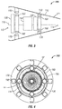
- FIG. 1 is a schematic side view of an internal concentric ring generator in accordance with some disclosed embodiments.
- generator 100 may be integrated into a turbine engine 110.
- turbine engine 110 will have an intake portion 112 and an exhaust portion 114.
- An engine shaft 120 will rotate a compressor 130 to draw in air from intake portion 112 and direct it into a combustion chamber 140 and out through turbine 150 and exhaust portion 114.
- embodiments of generator 100 may comprise one or more rotors 160 that are integrally formed in any of the compressor 130, turbine 150, or both.
- rotor 160 may comprise an outer portion of compressor 130, or rotor 160 may comprise a separate structure, such as a magnetized ring, or segments of permanent magnets that is mounted on an outer portion of compressor 130 and enabled to rotate therewith. Similar configurations may also be located at the turbine 150, or both compressor 130 and turbine 150 may include a rotor 160, as shown in FIG. 1 .
- embodiments of generator 100 may also comprise one or more stators 170.
- each stator 170 is mounted internally in engine 110 and encircles rotor 160.
- each stator 170 is mounted externally to engine 110 and encircles rotor 160 internal to engine 110.
- other combinations of internal and external mounting may be used.
- Rotor 160 and stator 170 may comprise any suitable components of an electrical machine and will further comprise coils, windings, magnets, ferrous materials, or the like to enable the generation of electrical current. As is also typical, rotor 160 will rotate under the influence of the forces generated by the engine 110 and stator 170 will remain generally stationary. Furthermore, either rotor 160 or stator 170 may comprise one or the other of the field producing component and the current producing component (i.e., armature).
- FIG. 3 is a schematic side view of an internal concentric ring generator in accordance with some disclosed embodiments.
- rotors 160 may comprise discrete components separate from either compressor 130 or turbine 150. Rotors 160 may be connected to shaft 120 and will still rotate under the influence of engine 110.
- a first rotor 160 is shown as being mounted "downstream” of compressor 130 and a second rotor (160) "upstream” of turbine 150, the generator 100 is not so limited and other mounting locations of rotor(s) 160 may be used.
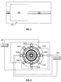
- FIG. 4 is a schematic front view of an external concentric ring generator 100 in accordance with some disclosed embodiments.
- both the rotor 160 and stator 170 are externally mounted, concentrically, on the engine 110 and one or more gears 180 may be used to impart the motion of the engine shaft 120 to the rotor 160.
- gears 180 may be part of planetary gearing system selected to rotate rotor 160 at any desired rotations per minute ("RPM").
- RPM rotations per minute
- other gearing, or transmission systems may also be implemented.
- embodiments of the generator 100 may also include discrete stator coils 190 that may further comprise moveable portions that enable the movement of the coils 190 to change the field strength, the current, or the voltage produced by the generator 100.
- FIG. 5 is a schematic illustration of a movable stator coil 190 in accordance with some disclosed embodiments.
- stator coils 190 may be mounted on a positioning means 200 so that coil 190 may be moved "closer” or “farther” from the rotor 160.
- Positioning means 200 may comprise a mechanical positioner such as a screw jack, a rack and pinion gear system, levers, hinged arms, or the like that enable the motion of the coil 190 back-and-forth radially with respect to rotor 160, and, generally will comprise an actuator 210 and a reciprocal biasing member 220.
- actuator 210 may comprise the screw portion of a screw jack and the reciprocal biasing member may comprise the reversible motor that drives the screw in the forward or reverse direction that moves the coil 190 back-and-forth.
- Positioning means 200 may also comprise a pneumatic, hydraulic, or other pressure-based position changer. As indicated schematically in FIG. 5 , for embodiments when positioning means 200 comprises a pressure-based system it may include an actuator 210 at a first pressure and reciprocal biasing side 220 that is at a different pressure and can be used to bias the stator coil 190 in the opposite direction as the actuator 210.
- positioning means 200 may also comprise piezo-electric or other electrical transducer that can be used to position the coils 190 by changing the current or voltage to the transducer.
- positioning means 200 may be used as a safety mechanism by enabling a stator coil 190 to be "dumped” or removed from the system if it shorts or otherwise fails by moving the coil 190 out of range of the rotor 160.
- stator coils 190 can function as a voltage regulator as follows. In general, the closer the stator coil 190 is to the rotor 160 the greater the voltage and power it will generate. Further, for embodiments of the generator 100 that are operated under a variable source of mechanical power (e.g., when turbine engine 110 is part of an aircraft that experiences different speeds during flight) the voltage of the generator 100 will increase as the RPM of the engine 110 turns the rotor 160 faster. Therefore, by using positioning means 200 to "back out" the stator coils 190 as the R.P.M. of the rotor 160 (and engine 110) increase, the voltage of the generator 100 can be substantially kept at the desired level.
- FIG. 6 is a schematic representation of electrically reconfigurable embodiments of the generator 100.
- Use of the independent stator coils 190 allows for independent and individualized wiring of the coils 190 so that different loads may be accommodated by generator 100. This is particularly useful in the aircraft environment where the electrical needs of aircraft sub-systems (e.g., navigation, radar, weapons systems) can vary and cause interference with each other, in particular when powered by a common generator.
- one set of coils 190A may be wired to power a first load 230 while a different set of coils 190B may be wired to power a second load 240.
- an increased set of coils 190B may be used to power higher electrical power loads and a lesser set 190A may be used for lower electrical power loads.
- other coils 190C may be used for other loads, may remain out of use, be used as a backup, or the like.
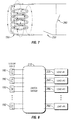
- FIG. 7 is a schematic representation of a bypass mechanism in accordance with some disclosed embodiments. This may be implemented with the independent stator coils 190 as follows. Coil 190 may short or otherwise fail and this failure condition may be indicated by an appropriate sensor (not shown) such as a temperature sensor, current sensor, voltage sensor, or the like. If such a condition is sensed, switch 250 may open to remove the coil 190 from the power generation circuit and switch 260 may close to enable another coil (not shown) to replace coil 190 in the circuit. Of course, this sensing and switching may be automated by appropriate control logic, or the like.
- FIG. 8 is a schematic representation of a switching matrix in accordance with disclosed embodiments.
- each stator coil 190 is connected to a switch matrix 270 which enables the selective switching of one or more of the stator coils 190 to one or more of the loads (e.g., 230, 240, 280, 290).
- the number of coils 190 can be matched to the size or need of the loads (e.g., 230, 240, 280, 290).
Landscapes
- Engineering & Computer Science (AREA)
- Power Engineering (AREA)
- Mechanical Engineering (AREA)
- General Engineering & Computer Science (AREA)
- Manufacturing & Machinery (AREA)
- Connection Of Motors, Electrical Generators, Mechanical Devices, And The Like (AREA)
Abstract
Description
- This disclosure relates to electric generators, and more particularly to concentric ring generators for advantageous use in aircraft having gas turbine engines.
- In general, military and commercial aircraft are increasingly relying on electrical systems to perform functions that were previously performed by mechanical or hydraulic systems. In general, some manufacturers are working to manufacture an "all electric" aircraft that has reduced weight and, thus, has increased fuel efficiency and/or range.
- Moreover, modern communication, navigation, avionics, weapons systems, etc., are consuming ever increasing amounts of electric power. As a result, power demands on the existing aircraft power plant are increasing and expected to continue increasing in the future. For example, some known aircraft generators currently in service are capable of generating approximately 100kW of electric energy. While this quantity of energy is sufficient to meet today's typical aircraft energy requirements, it may not be sufficient to meet future energy requirements as discussed above.
- One solution to meeting additional power needs is to install a larger, higher output generator to meet the increased energy demands. However, installing a larger generator is often not feasible on modern aircraft. For example, the aircraft may not have enough "open space" to accommodate the physical size of a larger generator. For example, at least some known aircraft generators are driven by a single power take-off ("PTO") shaft that also drives many other hydraulic and pneumatic pumps. As discussed above, as electrical power requirements increase, the torques and stresses on the PTO shaft due to a larger generator would also increase significantly. Additionally, it is often not practical to modify the aircraft to support a larger generator for cost and other reasons. Other drawbacks and disadvantages with current aircraft generators may also exist.
- Accordingly, the disclosed systems and methods substantially address the above-noted drawbacks and disadvantages of existing systems. In general, the disclosed generator incorporates a concentric ring design that may be incorporated internally within a turbine engine, such as an aircraft engine, or externally around the outer surface of the engine, or in combinations of internal and external mounting. In so configuring the generator, it affords a relatively larger surface area for the stator coils of the generator and, in some embodiments, allows for the radial positioning of independent stator coils with respect to the rotor, which may be used to regulate output power and voltage as disclosed herein.
- In addition, the disclosed systems and methods allow for an efficient step down (buck) of the relatively high voltage created by embodiments of the disclosed generator, as compared to the step up (boost) required by conventional aircraft generators. Likewise, embodiments of the disclosed generator enable variable frequency output that may be advantageous in some applications.
- Embodiments of the disclosed generator also enable manufacturing of a generator with relatively less copper (in coils or windings) while allowing for higher voltages (with increased insulation). Furthermore, the concentric configuration enables a relatively simpler mechanical connection with the engine and may eliminate the need for PTO shafts or other transmissions. For embodiments that rely on planetary gearing, the loads and torques on the generator and engine can be distributed over numerous gears. Other advantages also exist.
- Accordingly, disclosed embodiments include a generator comprising a turbine engine comprising a shaft, a compressor, and a turbine, a rotor in mechanical communication with the shaft and configured to be rotated by motion of the shaft, a stator comprising at least one coil wherein the stator is disposed radially outward of the rotor and wherein rotation of the rotor within the stator causes the generation of electric power. In some embodiments, the rotor and the stator are concentric with the shaft of the turbine engine. In some embodiments, the rotor further comprises a permanent magnet rotor.
- In some embodiments the generator includes a housing substantially enclosing the turbine engine and the stator is mounted substantially inside the housing. In some embodiments, the stator is mounted substantially outside the housing.
- In some embodiments, the generator includes a transmission to transfer motion of the shaft to the rotor, and the rotor and stator are concentrically mounted substantially outside the housing. In some embodiments, the transmission further comprises at least one gear in mechanical communication with the rotor and imparting rotational motion to the rotor in response to motion of the shaft. In some embodiments, the at least one gear is a planetary gear.
- In some embodiments, the generator further includes positioning means for moving the at least one coil. In some embodiments, the positioning means enables the at least one coil to move radially with respect to the rotor.
- The positioning means may comprise an actuator and a reciprocal biasing member, both acting on the at least one coil in opposite directions. In some embodiments the positioning means may comprise a pneumatic, hydraulic or other pressure-based position changer. In other embodiments the positioning means may include a piezo-electric or other electrical transducer.
- In some embodiments the positioning means may be operable to move the at least one coil so as to establish and/or maintain a predetermined output voltage of the generator. In other embodiments the positioning means may be operable to move the at least one coil out of range of the at least one rotor in case of failure of the coil.
- In some embodiments the stator may include a plurality of independent stator coils which may be individually wired to power different loads. In some embodiments each stator coil may be connected to a switch matrix which enables selective switching of one or more stator coils to one or more loads.
- Also disclosed is a method of manufacturing a generator comprising connecting a rotor in mechanical communication with a shaft of a turbine engine so that the rotor is rotated by motion of the shaft, positioning a stator comprising at least one coil radially outward of the rotor, concentric with the rotor and the shaft of the turbine engine, and wherein rotation of the rotor within the stator causes the generation of electric power.
- In some embodiments, the method further comprises mounting the stator substantially inside a housing of the turbine engine. In some embodiments, the method further comprises mounting the stator substantially outside a housing of the turbine engine.
- In some embodiments, the method of manufacturing further comprises concentrically mounting the rotor and stator substantially outside a housing of the turbine engine, connecting a transmission to transfer motion of the shaft to the rotor, and providing positioning means for moving the at least one coil.
- Also disclosed is a concentric generator comprising a turbine engine comprising a shaft, a compressor, and a turbine, a rotor, mounted concentrically with the shaft, and in mechanical communication with the shaft wherein the rotation of the shaft causes rotation of the rotor, a stator comprising at least one movable coil positioned concentrically and radially outward of the rotor and wherein rotation of the rotor within the stator causes the generation of electric power.
- In some embodiments, the turbine engine further comprises a housing and the stator is mounted substantially outside the housing. In some embodiments, the stator is mounted substantially inside the housing.
- In some embodiments the generator is manufactured such that the rotor is formed integrally with at least one of the compressor and turbine. In some embodiments, the rotor and compressor are both in mechanical communication with the shaft. In some embodiments, the rotor and turbine are both in mechanical communication with the shaft. Other advantages and characteristics of the disclosed embodiments will be apparent from the following detailed description.
-
-
FIG. 1 is a schematic side view of an internal concentric ring generator in accordance with some disclosed embodiments. -
FIG. 2 is a schematic side view of a concentric ring generator with an external stator in accordance with some disclosed embodiments. -
FIG. 3 is a schematic side view of an internal concentric ring generator in accordance with some disclosed embodiments. -
FIG. 4 is a schematic front view of an external concentric ring generator in accordance with some disclosed embodiments. -
FIG. 5 is a schematic illustration of a movable stator coil in accordance with some disclosed embodiments. -
FIG. 6 is a schematic representation of electrically reconfigurable embodiments of the concentric ring generator. -
FIG. 7 is a schematic representation of a bypass mechanism in accordance with some disclosed embodiments. -
FIG. 8 is a schematic representation of a switching matrix in accordance with disclosed embodiments. - While the disclosure is susceptible to various modifications and alternative forms, specific embodiments have been shown by way of example in the drawings and will be described in detail herein. However, it should be understood that the disclosure is not intended to be limited to the particular forms disclosed. Rather, the intention is to cover all modifications, equivalents and alternatives falling within the spirit and scope of the invention as defined by the appended claims.
- In general, a
concentric ring generator 100 is disclosed. In some embodiments, thegenerator 100 is used in conjunction with aturbine engine 110, such as a gas turbine engine commonly used on jet aircraft. Thegenerator 100 may be driven by theturbine 110 on-board an aircraft. Thegenerator 100 includes two sets ofrotors 160 andstators 170 generally arranged in a concentric fashion. In some embodiments, eachrotor 160 is ring shaped with an inner diameter that is sized to be located radially outward from theturbine engine 110. In some embodiments, thegenerator 100 is configured to be placed around theturbine engine 110. In other embodiments, thegenerator 100 may be integral with theturbine engine 110. For embodiments where thegenerator 100 encircles theturbine engine 110, appropriate gearing may be used (e.g.,planetary gears 180 shown inFIG. 4 ) to enable theturbine engine 110 to drive the rotor(s) 160. - In some embodiments,
generator 100 may include astator 170 that is capable of moving with respect to therespective rotor 160 and thereby, among other things, being able to control the amount of generated output current. For example, in some embodiments, at least portions ofstator 170 may be movable radially outward with respect to therespective rotor 160 to control the amount of current generated bygenerator 100. Other embodiments may also move the coils out of the field in directions other than radially. -
FIG. 1 is a schematic side view of an internal concentric ring generator in accordance with some disclosed embodiments. As showngenerator 100 may be integrated into aturbine engine 110. As schematically indicatedturbine engine 110 will have anintake portion 112 and anexhaust portion 114. Anengine shaft 120 will rotate acompressor 130 to draw in air fromintake portion 112 and direct it into acombustion chamber 140 and out throughturbine 150 andexhaust portion 114. - As shown in
FIG. 1 , embodiments ofgenerator 100 may comprise one ormore rotors 160 that are integrally formed in any of thecompressor 130,turbine 150, or both. For example,rotor 160 may comprise an outer portion ofcompressor 130, orrotor 160 may comprise a separate structure, such as a magnetized ring, or segments of permanent magnets that is mounted on an outer portion ofcompressor 130 and enabled to rotate therewith. Similar configurations may also be located at theturbine 150, or bothcompressor 130 andturbine 150 may include arotor 160, as shown inFIG. 1 . - As shown in
FIG. 1 , embodiments ofgenerator 100 may also comprise one ormore stators 170. For the embodiment shown inFIG. 1 eachstator 170 is mounted internally inengine 110 and encirclesrotor 160. For the embodiment shown inFIG. 2 , eachstator 170 is mounted externally toengine 110 and encirclesrotor 160 internal toengine 110. In addition, other combinations of internal and external mounting may be used. -
Rotor 160 andstator 170 may comprise any suitable components of an electrical machine and will further comprise coils, windings, magnets, ferrous materials, or the like to enable the generation of electrical current. As is also typical,rotor 160 will rotate under the influence of the forces generated by theengine 110 andstator 170 will remain generally stationary. Furthermore, eitherrotor 160 orstator 170 may comprise one or the other of the field producing component and the current producing component (i.e., armature). -
FIG. 3 is a schematic side view of an internal concentric ring generator in accordance with some disclosed embodiments. In the embodiments shown inFIG. 3 ,rotors 160 may comprise discrete components separate from eithercompressor 130 orturbine 150.Rotors 160 may be connected toshaft 120 and will still rotate under the influence ofengine 110. In addition, while afirst rotor 160 is shown as being mounted "downstream" ofcompressor 130 and a second rotor (160) "upstream" ofturbine 150, thegenerator 100 is not so limited and other mounting locations of rotor(s) 160 may be used. -
FIG. 4 is a schematic front view of an externalconcentric ring generator 100 in accordance with some disclosed embodiments. For this embodiment, both therotor 160 andstator 170 are externally mounted, concentrically, on theengine 110 and one ormore gears 180 may be used to impart the motion of theengine shaft 120 to therotor 160. As indicated, gears 180 may be part of planetary gearing system selected to rotaterotor 160 at any desired rotations per minute ("RPM"). Of course, other gearing, or transmission systems, may also be implemented. - As also illustrated in
FIG. 4 , embodiments of thegenerator 100 may also include discrete stator coils 190 that may further comprise moveable portions that enable the movement of thecoils 190 to change the field strength, the current, or the voltage produced by thegenerator 100. -
FIG. 5 is a schematic illustration of amovable stator coil 190 in accordance with some disclosed embodiments. As illustrated schematically inFIG. 5 , stator coils 190 may be mounted on a positioning means 200 so thatcoil 190 may be moved "closer" or "farther" from therotor 160. Positioning means 200 may comprise a mechanical positioner such as a screw jack, a rack and pinion gear system, levers, hinged arms, or the like that enable the motion of thecoil 190 back-and-forth radially with respect torotor 160, and, generally will comprise anactuator 210 and areciprocal biasing member 220. For example,actuator 210 may comprise the screw portion of a screw jack and the reciprocal biasing member may comprise the reversible motor that drives the screw in the forward or reverse direction that moves thecoil 190 back-and-forth. - Positioning means 200 may also comprise a pneumatic, hydraulic, or other pressure-based position changer. As indicated schematically in
FIG. 5 , for embodiments when positioning means 200 comprises a pressure-based system it may include anactuator 210 at a first pressure andreciprocal biasing side 220 that is at a different pressure and can be used to bias thestator coil 190 in the opposite direction as theactuator 210. - In addition, embodiments of positioning means 200 may also comprise piezo-electric or other electrical transducer that can be used to position the
coils 190 by changing the current or voltage to the transducer. - In general, positioning means 200 may be used as a safety mechanism by enabling a
stator coil 190 to be "dumped" or removed from the system if it shorts or otherwise fails by moving thecoil 190 out of range of therotor 160. - In addition, the movement of stator coils 190 can function as a voltage regulator as follows. In general, the closer the
stator coil 190 is to therotor 160 the greater the voltage and power it will generate. Further, for embodiments of thegenerator 100 that are operated under a variable source of mechanical power (e.g., whenturbine engine 110 is part of an aircraft that experiences different speeds during flight) the voltage of thegenerator 100 will increase as the RPM of theengine 110 turns therotor 160 faster. Therefore, by using positioning means 200 to "back out" the stator coils 190 as the R.P.M. of the rotor 160 (and engine 110) increase, the voltage of thegenerator 100 can be substantially kept at the desired level. -
FIG. 6 is a schematic representation of electrically reconfigurable embodiments of thegenerator 100. Use of the independent stator coils 190 allows for independent and individualized wiring of thecoils 190 so that different loads may be accommodated bygenerator 100. This is particularly useful in the aircraft environment where the electrical needs of aircraft sub-systems (e.g., navigation, radar, weapons systems) can vary and cause interference with each other, in particular when powered by a common generator. As shown inFIG. 6 , one set ofcoils 190A may be wired to power afirst load 230 while a different set ofcoils 190B may be wired to power asecond load 240. As represented schematically, an increased set ofcoils 190B may be used to power higher electrical power loads and alesser set 190A may be used for lower electrical power loads. In addition,other coils 190C may be used for other loads, may remain out of use, be used as a backup, or the like. -
FIG. 7 is a schematic representation of a bypass mechanism in accordance with some disclosed embodiments. This may be implemented with the independent stator coils 190 as follows.Coil 190 may short or otherwise fail and this failure condition may be indicated by an appropriate sensor (not shown) such as a temperature sensor, current sensor, voltage sensor, or the like. If such a condition is sensed, switch 250 may open to remove thecoil 190 from the power generation circuit and switch 260 may close to enable another coil (not shown) to replacecoil 190 in the circuit. Of course, this sensing and switching may be automated by appropriate control logic, or the like. -
FIG. 8 is a schematic representation of a switching matrix in accordance with disclosed embodiments. In such embodiments, eachstator coil 190 is connected to aswitch matrix 270 which enables the selective switching of one or more of the stator coils 190 to one or more of the loads (e.g., 230, 240, 280, 290). In this manner, the number ofcoils 190 can be matched to the size or need of the loads (e.g., 230, 240, 280, 290). - Although various embodiments have been shown and described, the present disclosure is not so limited and will be understood to include all such modifications and variations are would be apparent to one skilled in the art.
- Further, the disclosure comprises embodiments according to the following clauses:
- Clause 1: A generator comprising:
- a turbine engine comprising a shaft, a compressor, and a turbine;
- a rotor in mechanical communication with the shaft and configured to be rotated by motion of the shaft;
- a stator comprising at least one coil wherein the stator is disposed radially outward of the rotor and wherein rotation of the rotor within the stator causes the generation of electric power.
- Clause 2: The generator of
clause 1 wherein the rotor and the stator are concentric with the shaft of the turbine engine. - Clause 3: The generator of
clause 1 wherein the rotor further comprises a permanent magnet rotor. - Clause 4: The generator of
clause 1 further comprising:- a housing substantially enclosing the turbine engine; and
- wherein the stator is mounted substantially inside the housing.
- Clause 5: The generator of
clause 1 further comprising:- a housing substantially enclosing the turbine engine; and
- wherein the stator is mounted substantially outside the housing.
- Clause 6: The generator of
clause 1 further comprising:- a housing substantially enclosing the turbine engine;
- a transmission to transfer motion of the shaft to the rotor; and
- wherein the rotor and stator are concentrically mounted substantially outside the ousing.
- Clause 7: The generator of clause 6 wherein the transmission further comprises:
- at least one gear in mechanical communication with the rotor and imparting rotational motion to the rotor in response to motion of the shaft.
- Clause 8: The generator of clause 7 wherein the at least one gear is a planetary gear.
- Clause: 9 The generator of
clause 1 further comprising:- positioning means for moving the at least one coil.
- Clause 10: The generator of clause 9 wherein the positioning means enables the at least one coil to move radially with respect to the rotor.
- Clause 11: The generator of
clause 1 wherein the rotor is formed integrally with at least one of the compressor and turbine. - Clause 12: The generator of
clause 1 wherein the rotor and compressor are both in mechanical communication with the shaft. - Clause 13: The generator of
clause 1 wherein the rotor and turbine are both in mechanical communication with the shaft. - Clause 14: A method of manufacturing a generator comprising:
- connecting a rotor in mechanical communication with a shaft of a turbine engine so that the rotor is rotated by motion of the shaft;
- positioning a stator comprising at least one coil radially outward of the rotor, concentric with the rotor and the shaft of the turbine engine, and wherein rotation of the rotor within the stator causes the generation of electric power.
- Clause 15: The method of clause 14 wherein the step of positioning further comprises:
- mounting the stator substantially inside a housing of the turbine engine.
- Clause 16: The method of clause 14 wherein the step of positioning further comprises:
- mounting the stator substantially outside a housing of the turbine engine.
- Clause 17: The method of clause 14 further comprising:
- concentrically mounting the rotor and stator substantially outside a housing of the turbine engine;
- connecting a transmission to transfer motion of the shaft to the rotor; and
- providing positioning means for moving the at least one coil.
- Clause 18: A concentric generator comprising:
- a turbine engine comprising a shaft, a compressor, and a turbine;
- a rotor, mounted concentrically with the shaft, and in mechanical communication with the shaft wherein the rotation of the shaft causes rotation of the rotor;
- a stator comprising at least one movable coil positioned concentrically and radially outward of the rotor and wherein rotation of the rotor within the stator causes the generation of electric power.
- Clause 19: The concentric generator of clause 18 wherein the turbine engine further comprises a housing and the stator is mounted substantially outside the housing.
- Clause 20: The concentric generator of clause 18 wherein the turbine engine further comprises a housing and the stator is mounted substantially inside the housing.
Claims (15)
- A generator 100 comprising:a turbine engine (110) comprising a shaft (120), a compressor (130), and a turbine (150);at least one rotor (160) in mechanical communication with the shaft (120) and configured to be rotated by motion of the shaft (120);at least one stator (170) comprising at least one coil (190) wherein the at least one stator (170) is disposed radially outward of the at least one rotor (160) and wherein rotation of the at least one rotor (160) within the at least one stator (170) causes the generation of electric power.
- The generator (100) of claim 1 wherein the at least one rotor (160) and the at least one stator (170) are concentric with the shaft (120) of the turbine engine (110).
- The generator (100) of claim 1 or 2 wherein the at least one rotor (160) further comprises a permanent magnet rotor (160).
- The generator (100) of any one of the preceding claims further comprising:a housing (116) substantially enclosing the turbine engine (110); andwherein the at least one stator (170) is mounted substantially inside the housing (116).
- The generator (100) of any one of claims 1 to 3 further comprising:a housing (116) substantially enclosing the turbine engine (110); andwherein the at least one stator (170) is mounted substantially outside the housing (116).
- The generator (100) of any one of claims 1 to 3 further comprising:a housing (116) substantially enclosing the turbine engine (110);a transmission to transfer motion of the shaft to the at least one rotor; andwherein the at least one rotor (160) and at least one stator (170) are concentrically mounted substantially outside the housing (116).
- The generator (100) of any one of the preceding claims further comprising a transmission (182), wherein the transmission (182) comprises at least one gear (184) in mechanical communication with the at least one rotor (160) and imparting rotational motion to the at least one rotor (160) in response to motion of the shaft (120), wherein optionally the at least one gear is a planetary gear.
- The generator (100) of any one of the preceding claims further comprising:positioning means (200) for moving the at least one coil (190), wherein optionally the positioning means (200) enables the at least one coil (190) to move radially with respect to the at least one rotor (160).
- The generator (100) of any one of the preceding claims wherein the at least one rotor (160) is formed integrally with at least one of the compressor (130) and turbine (150).
- The generator (100) of any one of the preceding claims wherein the at least one rotor (160) is connected to the shaft (120) separately from either the compressor (130) or the turbine (150).
- The generator (100) of claim 10, wherein a plurality of rotors 160 are connected to the shaft (120).
- A method of manufacturing a generator comprising:connecting at least one rotor (160) in mechanical communication with a shaft (120) of a turbine engine (110) so that the at least one rotor (160) is rotated by motion of the shaft (120);positioning at least one stator (170) comprising at least one coil (190) radially outward of the at least one rotor (160), concentric with the at least one rotor (160) and the shaft (120) of the turbine engine (110), and wherein rotation of the at least one rotor (160) within the at least one stator (170) causes the generation of electric power.
- The method of claim 12 wherein the step of positioning further comprises:mounting the at least one stator (170) substantially inside a housing (116) of the turbine engine (110).
- The method of claim 12 wherein the step of positioning further comprises:mounting the at least one stator (170) substantially outside a housing (116) of the turbine engine (110).
- The method of claim 12 further comprising:concentrically mounting the at least one rotor (160) and at least one stator substantially outside a housing (116) of the turbine engine (110);connecting a transmission (182) to transfer motion of the shaft (120) to the at least one rotor (160); andproviding positioning means (200) for moving the at least one coil (190).
Applications Claiming Priority (1)
| Application Number | Priority Date | Filing Date | Title |
|---|---|---|---|
| US14/558,935 US9431877B2 (en) | 2014-12-03 | 2014-12-03 | Concentric ring generators |
Publications (3)
| Publication Number | Publication Date |
|---|---|
| EP3029814A2 true EP3029814A2 (en) | 2016-06-08 |
| EP3029814A3 EP3029814A3 (en) | 2016-07-06 |
| EP3029814B1 EP3029814B1 (en) | 2017-11-15 |
Family
ID=54770845
Family Applications (1)
| Application Number | Title | Priority Date | Filing Date |
|---|---|---|---|
| EP15196653.8A Active EP3029814B1 (en) | 2014-12-03 | 2015-11-27 | Concentric ring generators |
Country Status (2)
| Country | Link |
|---|---|
| US (1) | US9431877B2 (en) |
| EP (1) | EP3029814B1 (en) |
Cited By (2)
| Publication number | Priority date | Publication date | Assignee | Title |
|---|---|---|---|---|
| CN109667626A (en) * | 2017-08-22 | 2019-04-23 | 通用电气公司 | Turbine with turbine rotor blade alternately spaced apart |
| WO2024200967A1 (en) | 2023-03-31 | 2024-10-03 | Safran Aircraft Engines | Turbine engine module provided with an electric machine |
Families Citing this family (8)
| Publication number | Priority date | Publication date | Assignee | Title |
|---|---|---|---|---|
| US11022004B2 (en) * | 2017-03-31 | 2021-06-01 | The Boeing Company | Engine shaft integrated motor |
| US10704704B2 (en) * | 2017-07-14 | 2020-07-07 | Hamilton Sundstrand Coproration | Permanent magnet generator case vent valve |
| DE102017220941A1 (en) | 2017-11-23 | 2019-05-23 | Siemens Aktiengesellschaft | Electric machine with increased operational safety |
| US10644630B2 (en) | 2017-11-28 | 2020-05-05 | General Electric Company | Turbomachine with an electric machine assembly and method for operation |
| CN113847144A (en) * | 2021-09-28 | 2021-12-28 | 中国航空发动机研究院 | Turbine power generation device and power system |
| CN113958423B (en) * | 2021-10-20 | 2022-11-22 | 中国航空发动机研究院 | Bypass ratio adjustable fan for hybrid pure electric aircraft and aero-engine |
| US12480449B2 (en) | 2022-08-22 | 2025-11-25 | General Electric Company | Propulsion system including an electric machine for starting a gas turbine engine |
| US12448893B1 (en) | 2024-07-29 | 2025-10-21 | Pratt & Whitney Canada Corp. | Electromagnetic inducer for gas turbine rotating turbomachinery |
Family Cites Families (24)
| Publication number | Priority date | Publication date | Assignee | Title |
|---|---|---|---|---|
| US2610993A (en) * | 1951-07-12 | 1952-09-16 | Gen Electric | Adjustable magnetic shunt for permanent magnet generators |
| GB1041587A (en) * | 1962-08-27 | 1966-09-07 | Bristol Siddeley Engines Ltd | Improvements in gas turbine engines |
| US3143972A (en) * | 1963-02-06 | 1964-08-11 | Watt V Smith | Axial flow unit |
| CH606793A5 (en) * | 1975-12-02 | 1978-11-15 | Escher Wyss Ag | |
| US4367413A (en) * | 1980-06-02 | 1983-01-04 | Ramon Nair | Combined turbine and generator |
| US4577116A (en) * | 1983-11-14 | 1986-03-18 | The Boeing Company | System for providing electrical energy to a missile and the like |
| US4862009A (en) * | 1988-03-22 | 1989-08-29 | General Electric Company | Combined electric starter and alternator system using a permanent magnet synchronous machine |
| GB9311634D0 (en) | 1993-06-03 | 1993-07-21 | Spooner Edward | Electromagnetic machine |
| JPH08251894A (en) * | 1995-03-07 | 1996-09-27 | Daido Steel Co Ltd | Alternator with voltage control mechanism |
| US5874797A (en) * | 1996-12-10 | 1999-02-23 | Active Power, Inc. | Permanent magnet generator providing alternating current which has a selected frequency |
| US5834874A (en) * | 1997-09-30 | 1998-11-10 | Outboard Marine Corporation | Alternator with mechanically adjustable output |
| DK173641B1 (en) * | 1998-12-15 | 2001-05-14 | Bonus Energy As | Generator, preferably for a wind turbine |
| US6840479B1 (en) | 2003-12-05 | 2005-01-11 | The Boeing Company | Airframe mounted accessory drive (AMAD) power take-off shaft auxiliary power generation |
| DE102004004945A1 (en) * | 2004-01-31 | 2005-08-18 | Mtu Aero Engines Gmbh | Gas turbine, in particular aircraft engine |
| DE102004023569A1 (en) * | 2004-05-13 | 2005-12-08 | Mtu Aero Engines Gmbh | Aircraft engine |
| DE102006003884A1 (en) * | 2006-01-27 | 2007-08-02 | Mtu Aero Engines Gmbh | Jet engine with active magnetic bearing |
| CA2643598C (en) * | 2006-02-27 | 2014-09-09 | Hispano Suiza | Integration of a starter/generator module in a gas turbine transmission housing |
| WO2008026268A1 (en) * | 2006-08-31 | 2008-03-06 | Hitachi, Ltd. | Generator and gas turbine power generation facility |
| DE102006041323A1 (en) * | 2006-09-01 | 2008-03-06 | Rolls-Royce Deutschland Ltd & Co Kg | Generator-starter arrangement for a gas turbine engine |
| FR2926935B1 (en) * | 2008-01-30 | 2012-06-08 | Tecddis | AXIAL FLUX AND PERMANENT MAGNET ELECTRIC MACHINE |
| US8294290B2 (en) * | 2008-08-18 | 2012-10-23 | Aratec Engenharia Consultoria E Representacoes Ltda | Immersed magnet ring secured to radially outermost ends of hydraulic turbine blades and gap between rotor and stator filled with water |
| US8745990B2 (en) * | 2009-07-27 | 2014-06-10 | Rolls-Royce Corporation | Gas turbine engine with integrated electric starter/generator |
| US9850882B2 (en) * | 2011-05-19 | 2017-12-26 | Vestas Wind Systems A/S | Wind turbine generator with localized air gap control and a wind turbine having such a generator |
| DE102012201347A1 (en) * | 2012-01-31 | 2013-08-01 | Schaeffler Technologies AG & Co. KG | Electrical machine e.g. permanent-magnet synchronous motor for motor vehicle, has control unit that is arranged for detecting fault in the excitation magnetic field and for controlling actuator in case of error |
-
2014
- 2014-12-03 US US14/558,935 patent/US9431877B2/en active Active
-
2015
- 2015-11-27 EP EP15196653.8A patent/EP3029814B1/en active Active
Non-Patent Citations (1)
| Title |
|---|
| None |
Cited By (4)
| Publication number | Priority date | Publication date | Assignee | Title |
|---|---|---|---|---|
| CN109667626A (en) * | 2017-08-22 | 2019-04-23 | 通用电气公司 | Turbine with turbine rotor blade alternately spaced apart |
| CN109667626B (en) * | 2017-08-22 | 2022-05-10 | 通用电气公司 | Turbine with alternately spaced turbine rotor blades |
| WO2024200967A1 (en) | 2023-03-31 | 2024-10-03 | Safran Aircraft Engines | Turbine engine module provided with an electric machine |
| FR3147319A1 (en) * | 2023-03-31 | 2024-10-04 | Safran Aircraft Engines | TURBOMACHINE MODULE EQUIPPED WITH AN ELECTRIC MACHINE |
Also Published As
| Publication number | Publication date |
|---|---|
| US20160164372A1 (en) | 2016-06-09 |
| EP3029814A3 (en) | 2016-07-06 |
| US9431877B2 (en) | 2016-08-30 |
| EP3029814B1 (en) | 2017-11-15 |
Similar Documents
| Publication | Publication Date | Title |
|---|---|---|
| EP3029814B1 (en) | Concentric ring generators | |
| EP3763929B1 (en) | Gas turbine engine electrical generator | |
| EP3106648B1 (en) | Actuator control system and method for gas turbine engine | |
| US10773812B2 (en) | Hybrid electric aircraft battery charging | |
| US8857192B2 (en) | Accessory gearbox with a starter/generator | |
| US20180118369A1 (en) | Apparatus and methods for powering an electrical device associated with an aircraft rotor | |
| CN101205835A (en) | Integrated boost chamber ring generator for turbofan and turboshaft engines | |
| EP3957843A1 (en) | Hybrid through-flow gas turbine engine with electric motor and electric generator | |
| JP6130689B2 (en) | Device for extracting input power from a low-pressure spool of a turbine engine | |
| EP3575573B1 (en) | Hybrid amplification of high spool motoring via low spool power extraction and motoring of a differential geared generator | |
| EP3305665B1 (en) | Turbine engine having a counter-rotating electric generator | |
| US20160160867A1 (en) | Electrically coupled counter-rotation for gas turbine compressors | |
| US9973058B2 (en) | Propeller in-hub power generation and control | |
| US20220003128A1 (en) | Dual rotor electric machine | |
| EP3656998A1 (en) | Engine assembly | |
| US20090007569A1 (en) | High to low pressure spool summing gearbox for accessory power extraction and electric start | |
| WO2014196975A1 (en) | Jet engine assembly and method for generating electricity | |
| US11735988B2 (en) | Dual rotor electric machine | |
| EP4174298A1 (en) | Hybrid-electric single engine descent engine management | |
| EP2574759B1 (en) | Motor-generator turbomachine starter | |
| CN113054796A (en) | Starter/generator system | |
| JP2022519381A (en) | Drives, especially for the main rotors of rotary wing aircraft | |
| CN115279614A (en) | Speed reducer equipped with motor | |
| US20070157597A1 (en) | Aircraft engine | |
| US20250250940A1 (en) | Electrical system for aircraft propulsion system |
Legal Events
| Date | Code | Title | Description |
|---|---|---|---|
| PUAL | Search report despatched |
Free format text: ORIGINAL CODE: 0009013 |
|
| PUAI | Public reference made under article 153(3) epc to a published international application that has entered the european phase |
Free format text: ORIGINAL CODE: 0009012 |
|
| 17P | Request for examination filed |
Effective date: 20151127 |
|
| AK | Designated contracting states |
Kind code of ref document: A2 Designated state(s): AL AT BE BG CH CY CZ DE DK EE ES FI FR GB GR HR HU IE IS IT LI LT LU LV MC MK MT NL NO PL PT RO RS SE SI SK SM TR |
|
| AX | Request for extension of the european patent |
Extension state: BA ME |
|
| AK | Designated contracting states |
Kind code of ref document: A3 Designated state(s): AL AT BE BG CH CY CZ DE DK EE ES FI FR GB GR HR HU IE IS IT LI LT LU LV MC MK MT NL NO PL PT RO RS SE SI SK SM TR |
|
| AX | Request for extension of the european patent |
Extension state: BA ME |
|
| RIC1 | Information provided on ipc code assigned before grant |
Ipc: H02K 7/18 20060101AFI20160602BHEP |
|
| GRAP | Despatch of communication of intention to grant a patent |
Free format text: ORIGINAL CODE: EPIDOSNIGR1 |
|
| INTG | Intention to grant announced |
Effective date: 20170630 |
|
| GRAS | Grant fee paid |
Free format text: ORIGINAL CODE: EPIDOSNIGR3 |
|
| GRAA | (expected) grant |
Free format text: ORIGINAL CODE: 0009210 |
|
| AK | Designated contracting states |
Kind code of ref document: B1 Designated state(s): AL AT BE BG CH CY CZ DE DK EE ES FI FR GB GR HR HU IE IS IT LI LT LU LV MC MK MT NL NO PL PT RO RS SE SI SK SM TR |
|
| REG | Reference to a national code |
Ref country code: CH Ref legal event code: EP Ref country code: GB Ref legal event code: FG4D Ref country code: AT Ref legal event code: REF Ref document number: 947180 Country of ref document: AT Kind code of ref document: T Effective date: 20171115 |
|
| REG | Reference to a national code |
Ref country code: FR Ref legal event code: PLFP Year of fee payment: 3 |
|
| REG | Reference to a national code |
Ref country code: IE Ref legal event code: FG4D |
|
| REG | Reference to a national code |
Ref country code: DE Ref legal event code: R096 Ref document number: 602015006002 Country of ref document: DE |
|
| REG | Reference to a national code |
Ref country code: NL Ref legal event code: MP Effective date: 20171115 |
|
| REG | Reference to a national code |
Ref country code: LT Ref legal event code: MG4D |
|
| REG | Reference to a national code |
Ref country code: AT Ref legal event code: MK05 Ref document number: 947180 Country of ref document: AT Kind code of ref document: T Effective date: 20171115 |
|
| PG25 | Lapsed in a contracting state [announced via postgrant information from national office to epo] |
Ref country code: ES Free format text: LAPSE BECAUSE OF FAILURE TO SUBMIT A TRANSLATION OF THE DESCRIPTION OR TO PAY THE FEE WITHIN THE PRESCRIBED TIME-LIMIT Effective date: 20171115 Ref country code: SE Free format text: LAPSE BECAUSE OF FAILURE TO SUBMIT A TRANSLATION OF THE DESCRIPTION OR TO PAY THE FEE WITHIN THE PRESCRIBED TIME-LIMIT Effective date: 20171115 Ref country code: NO Free format text: LAPSE BECAUSE OF FAILURE TO SUBMIT A TRANSLATION OF THE DESCRIPTION OR TO PAY THE FEE WITHIN THE PRESCRIBED TIME-LIMIT Effective date: 20180215 Ref country code: NL Free format text: LAPSE BECAUSE OF FAILURE TO SUBMIT A TRANSLATION OF THE DESCRIPTION OR TO PAY THE FEE WITHIN THE PRESCRIBED TIME-LIMIT Effective date: 20171115 Ref country code: FI Free format text: LAPSE BECAUSE OF FAILURE TO SUBMIT A TRANSLATION OF THE DESCRIPTION OR TO PAY THE FEE WITHIN THE PRESCRIBED TIME-LIMIT Effective date: 20171115 Ref country code: LT Free format text: LAPSE BECAUSE OF FAILURE TO SUBMIT A TRANSLATION OF THE DESCRIPTION OR TO PAY THE FEE WITHIN THE PRESCRIBED TIME-LIMIT Effective date: 20171115 |
|
| PG25 | Lapsed in a contracting state [announced via postgrant information from national office to epo] |
Ref country code: BG Free format text: LAPSE BECAUSE OF FAILURE TO SUBMIT A TRANSLATION OF THE DESCRIPTION OR TO PAY THE FEE WITHIN THE PRESCRIBED TIME-LIMIT Effective date: 20180215 Ref country code: AT Free format text: LAPSE BECAUSE OF FAILURE TO SUBMIT A TRANSLATION OF THE DESCRIPTION OR TO PAY THE FEE WITHIN THE PRESCRIBED TIME-LIMIT Effective date: 20171115 Ref country code: HR Free format text: LAPSE BECAUSE OF FAILURE TO SUBMIT A TRANSLATION OF THE DESCRIPTION OR TO PAY THE FEE WITHIN THE PRESCRIBED TIME-LIMIT Effective date: 20171115 Ref country code: LV Free format text: LAPSE BECAUSE OF FAILURE TO SUBMIT A TRANSLATION OF THE DESCRIPTION OR TO PAY THE FEE WITHIN THE PRESCRIBED TIME-LIMIT Effective date: 20171115 Ref country code: GR Free format text: LAPSE BECAUSE OF FAILURE TO SUBMIT A TRANSLATION OF THE DESCRIPTION OR TO PAY THE FEE WITHIN THE PRESCRIBED TIME-LIMIT Effective date: 20180216 Ref country code: RS Free format text: LAPSE BECAUSE OF FAILURE TO SUBMIT A TRANSLATION OF THE DESCRIPTION OR TO PAY THE FEE WITHIN THE PRESCRIBED TIME-LIMIT Effective date: 20171115 |
|
| PG25 | Lapsed in a contracting state [announced via postgrant information from national office to epo] |
Ref country code: CY Free format text: LAPSE BECAUSE OF FAILURE TO SUBMIT A TRANSLATION OF THE DESCRIPTION OR TO PAY THE FEE WITHIN THE PRESCRIBED TIME-LIMIT Effective date: 20171115 Ref country code: EE Free format text: LAPSE BECAUSE OF FAILURE TO SUBMIT A TRANSLATION OF THE DESCRIPTION OR TO PAY THE FEE WITHIN THE PRESCRIBED TIME-LIMIT Effective date: 20171115 Ref country code: DK Free format text: LAPSE BECAUSE OF FAILURE TO SUBMIT A TRANSLATION OF THE DESCRIPTION OR TO PAY THE FEE WITHIN THE PRESCRIBED TIME-LIMIT Effective date: 20171115 Ref country code: SK Free format text: LAPSE BECAUSE OF FAILURE TO SUBMIT A TRANSLATION OF THE DESCRIPTION OR TO PAY THE FEE WITHIN THE PRESCRIBED TIME-LIMIT Effective date: 20171115 Ref country code: CZ Free format text: LAPSE BECAUSE OF FAILURE TO SUBMIT A TRANSLATION OF THE DESCRIPTION OR TO PAY THE FEE WITHIN THE PRESCRIBED TIME-LIMIT Effective date: 20171115 |
|
| REG | Reference to a national code |
Ref country code: DE Ref legal event code: R097 Ref document number: 602015006002 Country of ref document: DE |
|
| PG25 | Lapsed in a contracting state [announced via postgrant information from national office to epo] |
Ref country code: PL Free format text: LAPSE BECAUSE OF FAILURE TO SUBMIT A TRANSLATION OF THE DESCRIPTION OR TO PAY THE FEE WITHIN THE PRESCRIBED TIME-LIMIT Effective date: 20171115 Ref country code: LU Free format text: LAPSE BECAUSE OF NON-PAYMENT OF DUE FEES Effective date: 20171127 Ref country code: SM Free format text: LAPSE BECAUSE OF FAILURE TO SUBMIT A TRANSLATION OF THE DESCRIPTION OR TO PAY THE FEE WITHIN THE PRESCRIBED TIME-LIMIT Effective date: 20171115 Ref country code: IT Free format text: LAPSE BECAUSE OF FAILURE TO SUBMIT A TRANSLATION OF THE DESCRIPTION OR TO PAY THE FEE WITHIN THE PRESCRIBED TIME-LIMIT Effective date: 20171115 Ref country code: RO Free format text: LAPSE BECAUSE OF FAILURE TO SUBMIT A TRANSLATION OF THE DESCRIPTION OR TO PAY THE FEE WITHIN THE PRESCRIBED TIME-LIMIT Effective date: 20171115 |
|
| REG | Reference to a national code |
Ref country code: BE Ref legal event code: MM Effective date: 20171130 |
|
| REG | Reference to a national code |
Ref country code: IE Ref legal event code: MM4A |
|
| PLBE | No opposition filed within time limit |
Free format text: ORIGINAL CODE: 0009261 |
|
| STAA | Information on the status of an ep patent application or granted ep patent |
Free format text: STATUS: NO OPPOSITION FILED WITHIN TIME LIMIT |
|
| PG25 | Lapsed in a contracting state [announced via postgrant information from national office to epo] |
Ref country code: MT Free format text: LAPSE BECAUSE OF NON-PAYMENT OF DUE FEES Effective date: 20171127 |
|
| 26N | No opposition filed |
Effective date: 20180817 |
|
| PG25 | Lapsed in a contracting state [announced via postgrant information from national office to epo] |
Ref country code: IE Free format text: LAPSE BECAUSE OF NON-PAYMENT OF DUE FEES Effective date: 20171127 |
|
| PG25 | Lapsed in a contracting state [announced via postgrant information from national office to epo] |
Ref country code: SI Free format text: LAPSE BECAUSE OF FAILURE TO SUBMIT A TRANSLATION OF THE DESCRIPTION OR TO PAY THE FEE WITHIN THE PRESCRIBED TIME-LIMIT Effective date: 20171115 Ref country code: BE Free format text: LAPSE BECAUSE OF NON-PAYMENT OF DUE FEES Effective date: 20171130 |
|
| PG25 | Lapsed in a contracting state [announced via postgrant information from national office to epo] |
Ref country code: HU Free format text: LAPSE BECAUSE OF FAILURE TO SUBMIT A TRANSLATION OF THE DESCRIPTION OR TO PAY THE FEE WITHIN THE PRESCRIBED TIME-LIMIT; INVALID AB INITIO Effective date: 20151127 Ref country code: MC Free format text: LAPSE BECAUSE OF FAILURE TO SUBMIT A TRANSLATION OF THE DESCRIPTION OR TO PAY THE FEE WITHIN THE PRESCRIBED TIME-LIMIT Effective date: 20171115 |
|
| REG | Reference to a national code |
Ref country code: CH Ref legal event code: PL |
|
| PG25 | Lapsed in a contracting state [announced via postgrant information from national office to epo] |
Ref country code: CH Free format text: LAPSE BECAUSE OF NON-PAYMENT OF DUE FEES Effective date: 20181130 Ref country code: LI Free format text: LAPSE BECAUSE OF NON-PAYMENT OF DUE FEES Effective date: 20181130 |
|
| PG25 | Lapsed in a contracting state [announced via postgrant information from national office to epo] |
Ref country code: MK Free format text: LAPSE BECAUSE OF FAILURE TO SUBMIT A TRANSLATION OF THE DESCRIPTION OR TO PAY THE FEE WITHIN THE PRESCRIBED TIME-LIMIT Effective date: 20171115 |
|
| PG25 | Lapsed in a contracting state [announced via postgrant information from national office to epo] |
Ref country code: TR Free format text: LAPSE BECAUSE OF FAILURE TO SUBMIT A TRANSLATION OF THE DESCRIPTION OR TO PAY THE FEE WITHIN THE PRESCRIBED TIME-LIMIT Effective date: 20171115 |
|
| PG25 | Lapsed in a contracting state [announced via postgrant information from national office to epo] |
Ref country code: PT Free format text: LAPSE BECAUSE OF FAILURE TO SUBMIT A TRANSLATION OF THE DESCRIPTION OR TO PAY THE FEE WITHIN THE PRESCRIBED TIME-LIMIT Effective date: 20171115 |
|
| PG25 | Lapsed in a contracting state [announced via postgrant information from national office to epo] |
Ref country code: AL Free format text: LAPSE BECAUSE OF FAILURE TO SUBMIT A TRANSLATION OF THE DESCRIPTION OR TO PAY THE FEE WITHIN THE PRESCRIBED TIME-LIMIT Effective date: 20171115 Ref country code: IS Free format text: LAPSE BECAUSE OF FAILURE TO SUBMIT A TRANSLATION OF THE DESCRIPTION OR TO PAY THE FEE WITHIN THE PRESCRIBED TIME-LIMIT Effective date: 20180315 |
|
| P01 | Opt-out of the competence of the unified patent court (upc) registered |
Effective date: 20230516 |
|
| PGFP | Annual fee paid to national office [announced via postgrant information from national office to epo] |
Ref country code: DE Payment date: 20251128 Year of fee payment: 11 |
|
| PGFP | Annual fee paid to national office [announced via postgrant information from national office to epo] |
Ref country code: GB Payment date: 20251127 Year of fee payment: 11 |
|
| PGFP | Annual fee paid to national office [announced via postgrant information from national office to epo] |
Ref country code: FR Payment date: 20251125 Year of fee payment: 11 |