EP3029658B1 - Display board, method for pricing and display board arranged inside an automotive vehicle - Google Patents
Display board, method for pricing and display board arranged inside an automotive vehicle Download PDFInfo
- Publication number
- EP3029658B1 EP3029658B1 EP15198296.4A EP15198296A EP3029658B1 EP 3029658 B1 EP3029658 B1 EP 3029658B1 EP 15198296 A EP15198296 A EP 15198296A EP 3029658 B1 EP3029658 B1 EP 3029658B1
- Authority
- EP
- European Patent Office
- Prior art keywords
- display
- carrier part
- display panel
- display board
- film layer
- Prior art date
- Legal status (The legal status is an assumption and is not a legal conclusion. Google has not performed a legal analysis and makes no representation as to the accuracy of the status listed.)
- Active
Links
- 238000000034 method Methods 0.000 title claims description 6
- 239000011888 foil Substances 0.000 claims description 17
- 238000003780 insertion Methods 0.000 claims description 10
- 230000037431 insertion Effects 0.000 claims description 10
- 238000009423 ventilation Methods 0.000 claims description 7
- 238000005452 bending Methods 0.000 claims description 4
- 238000007493 shaping process Methods 0.000 claims description 2
- 230000007704 transition Effects 0.000 claims description 2
- 230000006378 damage Effects 0.000 claims 1
- 239000010410 layer Substances 0.000 description 61
- 239000002313 adhesive film Substances 0.000 description 16
- 239000000853 adhesive Substances 0.000 description 6
- 239000004033 plastic Substances 0.000 description 6
- 230000001070 adhesive effect Effects 0.000 description 4
- 230000002093 peripheral effect Effects 0.000 description 4
- 238000004026 adhesive bonding Methods 0.000 description 3
- 239000012790 adhesive layer Substances 0.000 description 3
- 229910052782 aluminium Inorganic materials 0.000 description 3
- XAGFODPZIPBFFR-UHFFFAOYSA-N aluminium Chemical compound [Al] XAGFODPZIPBFFR-UHFFFAOYSA-N 0.000 description 3
- 238000006073 displacement reaction Methods 0.000 description 3
- OKTJSMMVPCPJKN-UHFFFAOYSA-N Carbon Chemical compound [C] OKTJSMMVPCPJKN-UHFFFAOYSA-N 0.000 description 2
- 230000015572 biosynthetic process Effects 0.000 description 2
- 239000002131 composite material Substances 0.000 description 2
- 230000002349 favourable effect Effects 0.000 description 2
- 238000005755 formation reaction Methods 0.000 description 2
- 239000000463 material Substances 0.000 description 2
- 230000036961 partial effect Effects 0.000 description 2
- 229920000515 polycarbonate Polymers 0.000 description 2
- 239000004417 polycarbonate Substances 0.000 description 2
- 238000007639 printing Methods 0.000 description 2
- 230000002829 reductive effect Effects 0.000 description 2
- 239000007787 solid Substances 0.000 description 2
- 101100498160 Mus musculus Dach1 gene Proteins 0.000 description 1
- NIXOWILDQLNWCW-UHFFFAOYSA-N acrylic acid group Chemical group C(C=C)(=O)O NIXOWILDQLNWCW-UHFFFAOYSA-N 0.000 description 1
- 239000002390 adhesive tape Substances 0.000 description 1
- AZDRQVAHHNSJOQ-UHFFFAOYSA-N alumane Chemical group [AlH3] AZDRQVAHHNSJOQ-UHFFFAOYSA-N 0.000 description 1
- 229910052799 carbon Inorganic materials 0.000 description 1
- 239000011248 coating agent Substances 0.000 description 1
- 238000000576 coating method Methods 0.000 description 1
- 230000001427 coherent effect Effects 0.000 description 1
- 238000011109 contamination Methods 0.000 description 1
- 230000000694 effects Effects 0.000 description 1
- 238000005516 engineering process Methods 0.000 description 1
- 230000005484 gravity Effects 0.000 description 1
- 238000002372 labelling Methods 0.000 description 1
- 229910052751 metal Inorganic materials 0.000 description 1
- 239000002184 metal Substances 0.000 description 1
- 238000013021 overheating Methods 0.000 description 1
- 238000010422 painting Methods 0.000 description 1
- 230000035515 penetration Effects 0.000 description 1
- 239000006223 plastic coating Substances 0.000 description 1
- 229920000728 polyester Polymers 0.000 description 1
- 229920006267 polyester film Polymers 0.000 description 1
- 230000000717 retained effect Effects 0.000 description 1
- 230000003068 static effect Effects 0.000 description 1
- 238000004381 surface treatment Methods 0.000 description 1
- 230000003313 weakening effect Effects 0.000 description 1
Images


Classifications
-
- G—PHYSICS
- G09—EDUCATION; CRYPTOGRAPHY; DISPLAY; ADVERTISING; SEALS
- G09F—DISPLAYING; ADVERTISING; SIGNS; LABELS OR NAME-PLATES; SEALS
- G09F9/00—Indicating arrangements for variable information in which the information is built-up on a support by selection or combination of individual elements
- G09F9/30—Indicating arrangements for variable information in which the information is built-up on a support by selection or combination of individual elements in which the desired character or characters are formed by combining individual elements
- G09F9/37—Indicating arrangements for variable information in which the information is built-up on a support by selection or combination of individual elements in which the desired character or characters are formed by combining individual elements being movable elements
- G09F9/372—Indicating arrangements for variable information in which the information is built-up on a support by selection or combination of individual elements in which the desired character or characters are formed by combining individual elements being movable elements the positions of the elements being controlled by the application of an electric field
-
- G—PHYSICS
- G09—EDUCATION; CRYPTOGRAPHY; DISPLAY; ADVERTISING; SEALS
- G09F—DISPLAYING; ADVERTISING; SIGNS; LABELS OR NAME-PLATES; SEALS
- G09F21/00—Mobile visual advertising
- G09F21/04—Mobile visual advertising by land vehicles
- G09F21/048—Advertisement panels on sides, front or back of vehicles
- G09F21/0485—Advertising means on windshields
-
- G—PHYSICS
- G09—EDUCATION; CRYPTOGRAPHY; DISPLAY; ADVERTISING; SEALS
- G09F—DISPLAYING; ADVERTISING; SIGNS; LABELS OR NAME-PLATES; SEALS
- G09F21/00—Mobile visual advertising
- G09F21/04—Mobile visual advertising by land vehicles
- G09F21/048—Advertisement panels on sides, front or back of vehicles
-
- G—PHYSICS
- G09—EDUCATION; CRYPTOGRAPHY; DISPLAY; ADVERTISING; SEALS
- G09F—DISPLAYING; ADVERTISING; SIGNS; LABELS OR NAME-PLATES; SEALS
- G09F3/00—Labels, tag tickets, or similar identification or indication means; Seals; Postage or like stamps
- G09F3/08—Fastening or securing by means not forming part of the material of the label itself
- G09F3/18—Casings, frames or enclosures for labels
- G09F3/20—Casings, frames or enclosures for labels for adjustable, removable, or interchangeable labels
- G09F3/202—Casings, frames or enclosures for labels for adjustable, removable, or interchangeable labels for labels being formed by a combination of interchangeable elements, e.g. price labels
-
- G—PHYSICS
- G09—EDUCATION; CRYPTOGRAPHY; DISPLAY; ADVERTISING; SEALS
- G09F—DISPLAYING; ADVERTISING; SIGNS; LABELS OR NAME-PLATES; SEALS
- G09F3/00—Labels, tag tickets, or similar identification or indication means; Seals; Postage or like stamps
- G09F3/08—Fastening or securing by means not forming part of the material of the label itself
- G09F3/18—Casings, frames or enclosures for labels
- G09F3/20—Casings, frames or enclosures for labels for adjustable, removable, or interchangeable labels
- G09F3/203—Casings, frames or enclosures for labels for adjustable, removable, or interchangeable labels specially adapted to be attached to a transparent surface, e.g. the window of a car
-
- G—PHYSICS
- G09—EDUCATION; CRYPTOGRAPHY; DISPLAY; ADVERTISING; SEALS
- G09F—DISPLAYING; ADVERTISING; SIGNS; LABELS OR NAME-PLATES; SEALS
- G09F3/00—Labels, tag tickets, or similar identification or indication means; Seals; Postage or like stamps
- G09F3/08—Fastening or securing by means not forming part of the material of the label itself
- G09F3/18—Casings, frames or enclosures for labels
- G09F3/20—Casings, frames or enclosures for labels for adjustable, removable, or interchangeable labels
- G09F3/208—Electronic labels, Labels integrating electronic displays
Definitions
- the invention initially relates to an independently manageable display board according to the features of the preamble of claim 1.
- the invention also relates to an arrangement comprising a motor vehicle and a display board according to the features of the preamble of claim 11.
- the invention also relates to a method for displaying prices for a plurality of Motor vehicles according to the features of the preamble of claim 13.
- Display boards of the type in question are known. So the state of the art is about the DE 10 2013 106821 A1 or further on EP 1 729 273 A1 referred.
- the display panel can within a motor vehicle, for example according to figure 1 the mentioned EP specification. This more preferably in the opening of a ventilation slot.
- the display board can also have a plug-in projection, as is further illustrated in FIG DE 20 2010 008288 U1 is known.
- the insertion projection can otherwise be formed at the same level as the display panel or run at a (slightly) angled cross-section thereto.
- the carrier part from an aluminum or an aluminum composite material, preferably with a plastic coating facing the information element as the outer layer.
- the carrier part can also be designed as a plastic plate part, in particular made from polycarbonate or acrylic, and also from carbon.
- the display board or the support part preferably has a side length of up to 400 cm, for example with a rectangular floor plan.
- Such a display board is initially favorable for connection with an adhesive film, such as that from the EP 0 833 747 B1 is known, possibly also in the form of an adhesive bag, as from the EP 0 930 597 B1 is known.
- a display board is known in which a receiving element made of film plastic is attached to the rigid plate-like support part.
- the receiving element forms pockets.
- an elastic display is inserted as electronic paper. Wirings are formed from the plate-like supporting part to the pocket.
- US 6,307,919 B1 known to chemically fasten a display on the front side of a carrier part or by means of a press fit.
- the EP 0 689180 A1 discloses an electronic display as such provided with a front cover.
- the display board has a depression in which a digital photo element is arranged.
- a display board in which an information sheet can be held and the display board as a whole can be held on a sun visor of a motor vehicle.
- an electronic display unit for attachment to a shelf in a retail store is also known.
- the display is accommodated in a box-like receptacle which is covered by a lid part.
- the display is fixed inside the mount.
- the invention is concerned with the task of advantageously designing a display board of the type specified. Also to specify an arrangement comprising a motor vehicle and such a display board, as well as a method for displaying the price of a plurality of motor vehicles using such a display board.
- the wirelessly controllable display is in particular a display in the manner of a known e-paper.
- texts or images are preferably displayed permanently, without a conservation voltage being required for this.
- the display board has a display area that can be changed wirelessly.
- non-electronic displays such as in particular information elements in the form of sheets of paper and/or, for example, in the form of printing on the carrier part. In this way, a low-effort change, for example a price indication on the display board, can be carried out.
- the support part has a window-like opening and the display is visible through or in the opening, the display is integrated into the support part.
- displays which are arranged independently of one another in or on the display board, can also be provided. With regard to control, these displays can also be controlled in a coherent manner. However, it is preferred that they each form an independent, self-contained unit that can also be independently exchanged, for example.
- the display board can also have several information elements, which can also be held separately several times in the manner described here.
- a display can preferably be controlled via WLAN, Bluetooth or infrared. This wireless connection allows the display to be changed remotely without having to access the display board itself.
- the information element has a code, in particular a barcode, which is detected by a scanner and then, based on this barcode, because of the direct assignment, a connection is preferably created directly between the said scanner and the display - by radio technology so that this information or this price can then be transmitted to the display, if necessary via a third memory in which the associated information, in particular an associated price, is stored.
- the display or a control unit assigned to the display preferably has a unique identification for targeted control and programming of the display.
- the display can be provided with additional technical functional elements, such as an accumulator and/or a radio module and/or a control unit.
- the functional elements and the display can be provided in a common housing, with the display element designed in this way being assigned to a front side of the carrier part overall.
- the functional elements can also be provided in a housing part or housing part section that is separate from the display.
- the display and the possibly separate functional elements are attached directly to the carrier part. There is a detachable connection.
- a display is visible in particular on the front of the display board, ie the visible side which a user looks at to record the information to be conveyed.
- the display can only be integrated into the front of the display board with regard to its surface and can be used in the breakthrough from the rear of the display board.
- a visible outer surface of the display is arranged approximately at the same level as the front side of the carrier part.
- One or more ventilation holes can also be formed in the carrier part, assigned to an area in which the display is arranged or is to be arranged, in order to counteract overheating of the display, especially when the display board is arranged in a motor vehicle, e.g. behind a windshield .
- the display can be arranged on the back of the carrier part, visible through the opening from the front. The display is visible through or in the opening.
- a plug-in or slide-in definition is achieved.
- a holding element for the display is arranged on a rear side of the carrier part outside of the opening.
- the mounting element is thus not directly recognizable by a user who is looking at the front of the support part or the display panel as a whole.
- a display board can also be set up freely within a room, a user can of course recognize the holding element if he/she looks at the support part or the display board in this sense from the rear.
- the display is exchangeably held on the holding element.
- the holding element itself is firmly connected to the carrier part as a whole, which can only be removed by destroying it. Between the Display, possibly a rear extension of the display, and the support element is given a detachable connection.
- a first film layer is attached to the display board on the front side of the carrier element, preferably as part of a receiving pocket for an information element, and that the first film layer has a recess overlapping the opening.
- This film layer can be used to attach the holder for the information element, ie in particular the pocket as a whole, to the carrier part.
- the film layer can, for example, be glued to the relevant front side of the carrier part. Due to the fact that, more preferably, the said recess is provided in this film layer so that it overlaps the opening, the display—in relation to this film layer—is nevertheless directly exposed with regard to its visible surface.
- a second film layer is applied to the front side of the carrier element, which covers the first film layer and preferably also extends beyond it, and that the second film layer is designed to cover the display.
- the display is nevertheless covered and protected by the second film layer.
- a firmly attached foil layer can also be attached to the front side of the carrier part, optionally also as the only foil layer, and the display can be covered by this firmly attached foil layer.
- Such a fixed attachment can be achieved in particular by gluing.
- the firmly attached film layer merges into an area that is not firmly connected to the carrier part and can be distanced from the carrier part by bending out, for example.
- An information element can thus be accommodated in this area between the carrier part and the otherwise firmly attached film layer, which is then located between the non-permanently attached area of the film layer and the carrier part when in use.
- the invention further relates to a method for displaying the price of a plurality of motor vehicles.
- the invention is concerned with the task of specifying an advantageous method.
- a display change e.g. a change in the vehicle price
- a display change can be carried out remotely, while further information about the marked vehicle is retained, in particular via the information elements that cannot be changed by radio.
- the information elements that cannot be changed are, for example, printed sheets of paper and/or printed areas of a carrier part of the display board.
- Such information elements can also, as is also preferred, be film elements that are printed, for example, and have an adhesive film for direct attachment to the carrier part.
- Self-adhesive pockets for example foil pockets with an adhesive layer, can also be provided for holding sheets of paper, for example, for adhesion to the carrier part.
- a display reading that is valid for a plurality of motor vehicles can be changed via a central input point, preferably via a central computer.
- a change can also be made by an external device such as a smartphone or the like.
- parameters to be displayed can be advantageously adjusted over the duration of the labeling of the individual motor vehicles, such as the purchase price or financing offers being adjusted.
- the display can also be changed from a central location, so that a corresponding change, for example a purchase price of a specific model, can be carried out in a number of connected sales outlets simultaneously and without any effort for the on-site employees.
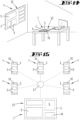
- a further display which is arranged outside of a motor vehicle, can be, for example, a wall display or a display integrated into a desk pad.
- a wall display for example, an employee has an overview of current prices or financing conditions by looking at his desk pad and/or by looking at a wall display.
- several such displays can be provided, for example in a wall display, for example assigned to different motor vehicles, each provided with a wirelessly controllable display.
- a controllable display in a writing pad can, for example, provide information about current financing conditions or about the current price of a motor vehicle model.
- the display board with the carrier part for both non-controllable information elements and for at least one wirelessly controllable display can be used as a plug-in or control element, for example.
- a plug-in or control element for example.
- the display board can also be designed as a table display, stand display or ceiling hanger, as well as a wall display or in the form of a desk pad.
- the object is to specify an advantageous arrangement.
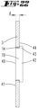
- An arrangement of such a display board that is favorable in terms of handling can be achieved on the inside of a motor vehicle windshield.
- the sun visor is preferably first detached on one side and swung aside.
- the display board can then be placed on the inside of the windshield in such a way that an elastically bendable end area of the display board is loaded by the sun visor, which has been brought back into its mounting position.
- the elastically bendable end portion of the display board is pressed against the inner surface of the windshield by the tension applied by the sun visor.
- the display board is held like this.
- the tension especially spring tension, results preferably solely from the material of the display panel or the plate-like support part and/or the plate geometry of the support part.
- the elastically bendable end region is preferably designed like a tongue.
- the end region can also have a line-like transition shape running transversely to a longitudinal extension of the display panel.
- the elastic deflection can be given in the sense of a reduction.
- a tongue-like section preferably extends at an obtuse angle to the plane extension of the adjoining carrier part.
- the reduction in the angling can extend to a parallelism of the angling area to the carrier part, possibly even beyond this, with which a quasi negative angling can be achieved in the loaded state.
- the angling is reduced by a load on the angling area of the sun visor brought into the holding position and, more preferably, into the usage position.
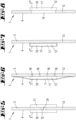
- a display board 1 which has an approximately rectangular plan, with an aspect ratio of 1:1.5 to 1:3 and a longer edge length of 10 to 150 cm. It serves, for example, as a price display board for a motor vehicle 2.
- the display board 1 has a rigid, plate-like support part 3 .
- the carrier part 3 consists, for example, of an aluminum composite material.
- An information element 5 is arranged on one side of the carrier part 3, assigned to a front side 4 in the exemplary embodiments. It can, for example, be printed paper.
- the carrier part 3 can be coated with a plastic layer, in particular on the front side 4 .
- a polyester coating is preferred in this regard.
- the information elements 5 are preferably designed to be attached to the front side 4 of the carrier part 3 so that they can be exchanged.
- an information element 5 in the form of printed paper according to the embodiment in FIGS Figures 1 and 2 be included in a foil pouch 6, which foil pouch 6 is attached to the carrier part 3 on the front side 4.
- the film pocket 6 leaves an insertion slot for the information element 5.
- the insertion slot is more preferred, see also figure 3 , given by simply lifting the top film, also described below in the form of an adhesive film 7.
- the information element 5 can also be a printed foil which is arrested according to adhesion on the front side 4 of the carrier part 3. In FIGS. 1 and 2, such self-adhesive information elements are provided with the reference number 5'.
- an information element 5" can be formed by directly printing an area of the carrier part 3, in particular its front side 4. Such an information element 5" is therefore not exchangeable.
- information elements 5 can be defined, for example in the form of printed sheets of paper, via an adhesive film 7 .
- an adhesive film 7 forms a cover for the information element 5, which cover is attached to the carrier part 3 by adhesion. Due to the fact that the adhesive film 7 protrudes beyond the information element 5 at the edge, it rests directly on the front side 4 of the carrier part 3 and can adhere there.
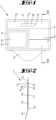
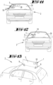
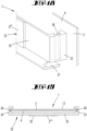
- the display board 1 has a square to rectangular outline. More preferably, an insertion section 8 is formed. With this plug-in section 8, the display board 1 can be plugged into a motor vehicle 2, for example by plugging it into a ventilation slot (cf. figure 12 ) or at least a plugging behind the windshield.
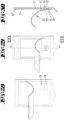
- the display panel 1 can also be provided for arrangement on a sun visor in the motor vehicle 2 (cf. figure 11 ), For example, as a result of a plug-in connection, such as these in particular from the initially cited DE 10 2013 106 821 A1 is known. Furthermore, the design of a display board 1 for arrangement on a motor vehicle roof is also known from the aforementioned patent application. In this case, the display board 1 has magnetic feet 9 for magnetic attachment to a metal part, here for example on the motor vehicle roof (cf. figure 13 ).
- an angled portion 25 can be provided in the area of one end side of the display panel 1, which forms a U-shape in cross section.
- one leg 26 of the U is formed by the display panel as such and the other leg 27 of the U, which is significantly shorter, is designed as an overlapping leg for the sun visor 28 .
- the two U-legs 26 and 27 are connected by a U-web 29. The length of this is preferably approximately adapted to the thickness of the sun visor 28 .
- the display board 1 is held on the sun visor 28 in the U-space by means of the angled portion 25 while partially accommodating the sun visor 28 .
- figure 17 shows an alternative mounting option for a display board 1 using the sun visor 28.
- the display board 1 can be mounted as shown in figure 2 be designed correspondingly with an insertion section 8 running at an angle in relation to the carrier part 3.
- the sun visor 28 is first, as further preferred, detached on one side from a holder (not shown) and swung aside.
- the display panel 1 is then leaned against the windshield 30 on the inside, with the information elements correspondingly facing the windshield 30 .
- the bend (insertion section 8) is thus stressed in such a way that it is reduced compared to the plate-like carrier part 3 (due to pivot displacement in Direction of parallelism to the carrier part 3).
- the display board 1 is clamped between the windshield 30 and the sun visor 28 .
- the display board 1 preferably has another information element 5′′′ in the form of a wirelessly controllable display 10.
- the display 10 can preferably be optionally arranged on the carrier part 3 .
- the display 10 more preferably works in the manner of an e-paper.
- the display 10 is also provided with functional elements 11, not shown in detail, such as a battery and/or a radio module and/or a control unit. Display 10 and functional elements 11 can be arranged in a common housing 12 .
- the display 10 and/or the functional elements 11 can be fixed in place by appropriately arranging an adhesive surface on the display 10 or on the functional elements 11 on the back 13, is accessible (see. Examples in the Figures 1 to 4 ).
- the adhesive layer can, for example, be an adhesive strip, which is optionally adjusted for removal from the carrier part 3 without leaving any residue.
- this unit is attached to the front side 4 of the carrier part 3.
- such a unit, but possibly only the display 10 can also be arranged on the back 13 as shown in FIG figure 8 possible, where in In this case, a window-like opening 14 is provided in the carrier part 3, through which the display 10 is visible.
- the display 10 can be arranged on the front side 4 and the functional elements 11 can be arranged on the back side 13, possibly overlapping it.
- An opening 15 in the carrier part 3 can be used to lead through lines 24 between the functional elements 11 and the display 10 .
- the carrier part 3 can have one or more ventilation holes 16, for example when a display board 1 designed in this way is arranged behind a windshield, in which arrangement temperatures of over 80 ° C can be achieved to achieve ventilation to the interior of the vehicle.
- the definition of the display 10, possibly together with the functional elements 11, can also be carried out according to the illustration in figure 6 can also be achieved via an adhesive film 7, as this can also be used to fix information elements 5 on the carrier part 3.
- the display 10 can also be arranged in a casing 17 together with the functional elements 11 (cf. figure 7 ).
- This covering 17 is designed for adhesive attachment to the partial carrier surface, in particular on the front side 4.
- the covering 17 is preferably formed at least facing the partial carrier surface in the manner of an adhesive film.
- the casing 17 can also be designed to protect against heat overall, in order to ensure proper operation of the display 10 even when a display board 1 designed or equipped in this way is arranged, for example behind a windshield of a motor vehicle.
- the housing 12 or the display 10 preferably extends over a length which essentially corresponds to the distance between two peripheral edges of the carrier part 3 running parallel to one another.
- a comparatively shorter display 10 can alternatively be provided with cantilevers 18 bridging this distance between the edges running parallel to one another.
- the brackets 18, possibly directly the display 10 or its housing 12, are provided with gripping sections 19, which grip through open-edged openings 20 provided on the edge of the carrier part 3 and, in the fixed position, at least partially on the back 13 of the Support carrier part 3.
- the display 10 can also be attached to the carrier part 3 via an elastic band that also extends over the rear side 13 using such openings 20 .
- projections can also be provided which protrude beyond the respective edge of the carrier part 3, in order to secure the display 10 to be fixed against displacement.
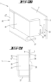
- the display 10 can also be attached to a holder 32 .
- the holder 32 is essentially U-shaped in relation to a floor plan, with a U-web 35 connecting the U-legs 33 and 34.
- the display 10 is attached to the U-web 35 on the outside.
- the U-legs 33 and 34 are designed to interact with mutually parallel peripheral edges of the carrier part 3 and for this purpose have groove-like recesses 36 which are essentially adapted to the material thickness of the carrier part 3 and are directed towards one another.
- the U-legs 33 and 34 are designed to engage behind the carrier part 3 in a latching manner.
- the display 10 can be spaced from the facing presentation side of the carrier part 3 by the holder 32 .
- Any gap that may result between the U-web 35 and the broad side of the carrier part 3 facing it can be covered on the underside by a bottom 37 that is molded on, for example.
- the holder 32 can be further supported on the surface of the carrier part 3 via the base 37 .
- Such an anti-slip device can also be achieved, for example, by appropriate surface treatment in the area of the recesses 36 .
- the edge of the base 37 facing the carrier part 3 can be provided with a self-adhesive layer, alternatively with a double-sided adhesive tape.
- FIGS. 20 and 21 show an alternative embodiment of a holder 32. This has associated with the U-legs 33 and 34 in each case a hook-shaped extension 38 for reaching through a dimensionally adapted slot 39 in the carrier part 3.
- the respective slot 39 is preferably covered by the associated U-leg 33, 34 when the holder 32 is in the holding position.
- the display 10 can be used, for example, to display a price, further, for example, a selling price of the motor vehicle 2.
- the display 10 can be changed wirelessly, for example using infrared, Bluetooth or WLAN.
- the change in the display of several display boards 1, which can, for example, each be assigned to the same type of vehicle, possibly with the same equipment, can be made from a central location 21, so that, for example, a price change for a specific motor vehicle model can also be made centrally in can be carried out in several houses at the same time.
- the displays 10 can be changed by the same control.
- a display 10 that is arranged outside of a motor vehicle 2 can also be correspondingly changed by the same control.
- a display 10 outside a motor vehicle can, for example, be part of a wall panel 22, on which wall panel 22 there can also be a plurality of wirelessly controllable displays 10 for displaying, for example, the prices of various existing motor vehicle models.
- the display 10 can also be part of a desk pad 23 .
- Blackboard 22 and/or desk pad 23 can be used as display boards in accordance with the exemplary embodiments described above and the prior art cited at the outset 1 be provided with a carrier part 3 and other information elements 5 to 5 ′′′.
- the carrier part (3) can accommodate the display (10) in the opening (14) in such a way that a visible side (40) of the display (10) is flush or almost flush with a visible side (41) of the carrier part (3).
- An alternative embodiment, which is also preferred at the time of filing, is in Figures 31 to 33 played back. After that, the display as a whole rests against the back of the carrier part and the front side of the display is aligned with a back side of the carrier part. Approximate alignment is still assumed if the visible side (40) protrudes beyond the visible side (41) or is backwards in the range of up to one half or two thirds of a thickness (d) of the carrier part (3).
- the term display 10 here preferably refers to the entirety of an actual display and of functional parts, as they are named above for the display.
- the display 10 can have a receiving area 42 in which one or more of the functional parts mentioned are arranged.
- the display 10 and here preferably the receiving area 42 can have an overlapping section 43 on one side, opposite or also circumferentially, with which they overlap over an outer side 44 of the carrier part 3 opposite the visible side 41 .
- a latching or gluing or connection produced in some other way between the carrier part 3 and the display 10 can be achieved.
- the attachment can preferably be provided in a detachable manner in order to be able to exchange a display 10, for example.
- a Velcro connection can be realized by a hook element on one side, such as the overlapping section 43, and on the opposite side of the carrier part 3 an eyelet element.
- an adhesive film can be attached to the assigned side of the carrier part 3, i.e. the outer side 44, at least in the area of the overlapping section 43 and in the assigned area of the carrier part 3 such a design in the form of a smooth surface, which enables adhesion by means of the adhesive film .
- the design can also be reversed, that is, the adhesive film is formed on the overlapping section 43 and the smooth area is provided by the outside 44 .
- the display can of course simply be glued to the carrier part.
- FIG. 23 A possibility of the exchangeable connection according to the claimed invention between the display 10 and the carrier part 3 is in figure 23 shown.
- a holding part 45 is attached to the outside 44 of the carrier part 3, adjacent to the opening 14.
- the mounting part 45 can be glued to the carrier part 3 .
- the display 10 has one or more latching formations 46 with which it is latched to the mounting part 45 .
- one, two, three or more, preferably distributed over the circumference of the display 10 , projecting, rod-like elements can be used as latching formations 46 on the display 10 .
- Two such elements can also be sufficient since tilting can already be prevented by a tight fit of the holding part part 45 on the assigned area of the display 10 .
- figure 24 shows a top view, in section, of the outer side 44 with the mounting part 45, the display 10 having been removed.
- figure 25 shows a perspective view of a possible more specific embodiment of the mounting part 45.
- a display board is shown, in which an opening 14 is formed in the carrier part 3, in which the display 10 is exposed to the outside.
- the carrier part 3 is covered with a first film layer 47 on its visible side 41 in the area of the opening 14 .
- the foil layer 47 can be connected to the carrier part 3 by adhesive bonding. However, it can also be glued to the carrier part 3, for example.
- This first film layer 47 has its own opening, a recess 48, so that with respect to the first film layer 47 direct access from the visible side of the carrier part 3 to the display 10 is nevertheless provided.
- visible outside or visible side 41 of the carrier part 3 refers to the outside of the carrier part that faces the viewer when in use, on which the information element is also arranged - at least partially overlapping.
- visible side 41 it is not important whether this side is actually visible during use, but only that it is that side of the carrier part 3 which faces the user in the manner mentioned.
- the display 10 is further covered by a second film layer 49 .
- This second film layer 49 is preferably provided, at least in the area of the display 10, so that it can be lifted off the carrier part 3 and also with respect to the first film layer 47.
- An information element can thus be inserted between the second film layer 49 and the first film layer 47, preferably outside of the display 10.
- the display 10 is nevertheless visible through the second film layer 49, which is in any case transparent in the area of the display 10. However, it is before direct contact and possibly also contamination by the second film layer 49 protected.
- the second film layer 49 can be formed in two layers, at least at the edge, in such a way that a layer 50 assigned to the carrier part 3 is designed as an adhesive film layer. Due to the two-layer structure, there is an overlap with respect to the first film layer 47 even without the fact that the second layer 50 is in the form of an adhesive film layer, if this, as in figure 27 is shown, associated with the second film layer 49 ends in front of this in surface extension.
- the further layer 51 of the second film layer 49 is preferably continuous and also completely overlaps layer 50.
- a display board 1 can also have several openings 14 .
- two openings 14 are shown, which - are arranged one above the other - based on a longitudinal extension of the display board 1 .
- a further embodiment of the display board 1 is shown, which is distinguished by the fact that on the visible side 41 of the carrier part 3 a film layer 52 is attached to the carrier part 3, at least over part of its surface.
- the film layer 52 can, for example, be glued or welded to the carrier part 3 in the region mentioned. The latter could be appropriate if the carrier part 3 consists of plastic or has a plastic surface.
- One or more openings 14 are formed in the area of the film layer 52 which is firmly connected to the carrier part 3 and which are also preferably provided with a display 10 in each case.
- the foil layer 52 preferably has a region 53 which is not attached to the carrier part 3 .
- the film layer 52 is in the area 53, as shown in FIG figure 30 seen, provided bent away with respect to the visible side 41 to an observer, so that an information element 5 can be inserted between the foil layer 52 and the carrier part 3 .
- the film layer 52 is preferably formed with such rigidity that it automatically moves back into its contact position when it is released when the information element 5 is inserted or in any case remains in the contact position when it is shifted back there.
- the film layer 52 can be configured as an adhesive film in the area 53 assigned to the carrier part 3, optionally also only at the edge. However, it can also be designed as a non-adhesive film, ie as a polyester film, for example, and accordingly only come into firm contact with the carrier part 3 by painting it by hand.
- the information element 5 is preferably designed to be smaller at the edge, resulting in an edge region in which the region 53 of the film layer 52 can rest directly on the outside of the carrier part 3 .
- the film layer 52 can also continue into a further area 52 ′, which is also firmly connected to the carrier part 3 .
- the area 52' can in particular, as in figure 30 shown, extend above the region 53 of the foil layer 52 . Moreover, it does not need to be connected to the foil layer 52 .
- the area 53 of the film layer 52 is provided so that the free end - based on the cross section according to figure 30 - extends opposite to a given by the bend 25 in the embodiment lower portion of the support part 3, so preferably an insertion area.
- gravity alone ensures that the information element 5 cannot fall out immediately when the area 53 is opened.
- the film layer 52 preferably extends directly into the area 53 with the same thickness without a fold, weakening or the like other attachment between the firmly attached area of the film layer 52 and the area 53 given.
- FIG 31 Another possible embodiment according to the claimed invention of a mounting part 45' is shown, here in a view of the rear of a carrier part 3.
- This mounting part 45' is arranged at a distance r from a peripheral edge of the opening 14 on the rear of the carrier part. It is preferably glued to the carrier part.
- the holding part 45' can be formed in a closed, circumferential manner in the manner of a frame. It is also possible for only one of the legs of the holding part 45', namely the leg on which the holding tongue 45 is formed, to be realized.
- the display 10 can then be inserted between the retaining tongue 54 and the rear side of the carrier part 3 . In 31 it is shown in the course of insertion.
- the display 10 then preferably lies within the edge of the mounting part 45 ′, in particular within the peripheral edge of the mounting part 45 ′, directly on a rear side of the carrier part 3 .
- the display 10 is designed as a modular overall unit, with all the necessary functional parts, in particular also with an accumulator and a battery for the independent power supply.
- the retaining tongue 54 is preferably designed in such a way that it bends open elastically, further retaining means are then not required.
- the display 10 is readily interchangeable.
- FIG 32 1 is a cross section through another embodiment of a housing, referred to herein as housing 12'.
- the housing essentially has a C-shape.
- the A continuous C-frame which however preferably also has a viewing window 55 formed as a through-opening, is arranged on the front side of the carrier part in the assembled state.
- the C-legs 56 and 57 enclose the carrier part 3. The cooperation is preferably such that a clamping connection between the housing 12' and the carrier part 3 results.
- the housing 12' can easily be slid onto the carrier part 3 from above and moved to its desired place in terms of height.
- a further frame part 59 is preferably attached to the rear of the continuous C-leg 58 on the inside, facing the carrier part 3 .
- the display 10 preferably in the form of the module already described, is removably accommodated.
- the frame part 59 is preferably formed circumferentially or at least on three or four sides with respect to the module 10, so that the module 10 cannot fall out onto the carrier part 3 even when the housing 12' is in place.
- the support part 3 can be unaffectedly continuous, that is to say without a breakthrough.
- the resulting second layer 50 related to the longitudinal edge of the rectangular display board shown, but in this respect also generally, has a window-like recess in the overlapping area that corresponds to the opening 14 or at least the visible surface of the display 10, round but is designed to be closed around this opening, so that the adhesive film, which preferably forms the second film layer 50, surrounds the opening 14 in a closed manner and also seals it accordingly in the covered state.
- the edges of the film layer 51 which are formed on the underside by the film layers 50, are of different widths as seen in the width extension of the display panel.
- On the side on which the opening 14 is formed there is a much greater width formed than on the opposite side.
Landscapes
- Physics & Mathematics (AREA)
- General Physics & Mathematics (AREA)
- Engineering & Computer Science (AREA)
- Theoretical Computer Science (AREA)
- Business, Economics & Management (AREA)
- Accounting & Taxation (AREA)
- Marketing (AREA)
- Devices For Indicating Variable Information By Combining Individual Elements (AREA)
- Fittings On The Vehicle Exterior For Carrying Loads, And Devices For Holding Or Mounting Articles (AREA)
- Instrument Panels (AREA)
- Electroluminescent Light Sources (AREA)
Description
Die Erfindung betrifft zunächst eine eigenständig handhabbare Schautafel nach den Merkmalen des Oberbegriffes des Anspruches 1. Weiter betrifft die Erfindung eine Anordnung umfassend ein Kraftfahrzeug und eine Schautafel nach den Merkmalen des Oberbegriffs des Anspruchs 11. Darüber hinaus betrifft die Erfindung ein Verfahren zur Preisauszeichnung einer Mehrzahl von Kraftfahrzeugen nach den Merkmalen des Oberbegriffs des Anspruchs 13.The invention initially relates to an independently manageable display board according to the features of the preamble of
Schautafeln der in Rede stehenden Art sind bekannt. So wird zum Stand der Technik etwa auf die
Bekannt ist in diesem Zusammenhang weiter, das Trägerteil aus einem Aluminium- oder einem Aluminium-Verbundmaterial herzustellen, mit bevorzugt einer dem Informationselement zugewandten Kunststoffbeschichtung als Außenlage. Auch kann das Trägerteil als Kunststoff-Plattenteil ausgebildet sein, insbesondere hergestellt aus Polycarbonat oder Acryl, darüber hinaus auch aus Karbon. Die Schautafel beziehungsweise das Trägerteil weist bevorzugt eine Seitenlänge von bis zu 400 cm auf, dies bei beispielsweise rechteckigem Grundriss.In this connection it is also known to produce the carrier part from an aluminum or an aluminum composite material, preferably with a plastic coating facing the information element as the outer layer. The carrier part can also be designed as a plastic plate part, in particular made from polycarbonate or acrylic, and also from carbon. The display board or the support part preferably has a side length of up to 400 cm, for example with a rectangular floor plan.
Eine solche Schautafel ist zunächst günstig zur Verbindung mit einer Haftfolie, wie sie etwa aus der
Aus der
Aus der
Aus der
Aus der
Aus der
Ausgehend von dem dargelegten Stand der Technik beschäftigt sich die Erfindung mit der Aufgabenstellung, eine Schautafel der angegebenen Art vorteilhaft auszubilden. Weiter auch eine Anordnung umfassend ein Kraftfahrzeug und eine derartige Schautafel anzugeben sowie ein Verfahren zur Preisauszeichnung einer Mehrzahl von Kraftfahrzeugen unter Nutzung einer solchen Schautafel.Proceeding from the prior art presented, the invention is concerned with the task of advantageously designing a display board of the type specified. Also to specify an arrangement comprising a motor vehicle and such a display board, as well as a method for displaying the price of a plurality of motor vehicles using such a display board.
Diese Aufgabe ist zunächst beim Gegenstand des Anspruches 1 gelöst.This object is initially achieved with the subject matter of
Bei dem drahtlos ansteuerbaren Display handelt es sich insbesondere um ein Display in Art eines bekannten E-Papers. Texte oder Bilder werden hierbei bevorzugt dauerhaft angezeigt, ohne dass hierfür eine Erhaltungsspannung erforderlich ist. Die Anzeige auf dem Display kann jedoch zu einem späteren Zeitpunkt geändert werden. Mit der Anordnung eines solchen Displays weist die Schautafel einen drahtlos änderbaren Anzeigebereich auf. Gegebenenfalls neben weiteren, nicht elektronischen Anzeigen, wie insbesondere Informationselementen in Form von Papierbögen und/oder bspw. in Form einer Bedruckung des Trägerteils. Derart ist eine aufwandarme Änderung bspw. einer Preisangabe auf der Schautafel durchführbar.The wirelessly controllable display is in particular a display in the manner of a known e-paper. In this case, texts or images are preferably displayed permanently, without a conservation voltage being required for this. However, what is shown on the display can be changed at a later date. With the arrangement of such a display, the display board has a display area that can be changed wirelessly. Possibly in addition to other, non-electronic displays, such as in particular information elements in the form of sheets of paper and/or, for example, in the form of printing on the carrier part. In this way, a low-effort change, for example a price indication on the display board, can be carried out.
Dadurch, dass das Trägerteil einen fensterartigen Durchbruch aufweist und das Display durch den oder in dem Durchbruch sichtbar ist, ist das Display in das Trägerteil integriert.Because the support part has a window-like opening and the display is visible through or in the opening, the display is integrated into the support part.
Es können auch mehrere Displays, die unabhängig voneinander in oder an der Schautafel angeordnet sind, vorgesehen sein. Hinsichtlich einer Steuerung können diese Displays auch zusammenhängend ansteuerbar sein. Bevorzugt ist jedoch, dass sie jeweils eine eigenständige abgeschlossene Einheit bilden, die beispielsweise auch jeweils eigenständig austauschbar ist.Several displays, which are arranged independently of one another in or on the display board, can also be provided. With regard to control, these displays can also be controlled in a coherent manner. However, it is preferred that they each form an independent, self-contained unit that can also be independently exchanged, for example.
Die Schautafel kann auch mehrere Informationselemente, die auch mehrfach in den hier beschriebenen Weisen gesondert gehaltert sein können, aufweisen.The display board can also have several information elements, which can also be held separately several times in the manner described here.
Ein Display ist bevorzugt über WLAN, Bluetooth oder auch Infrarot ansteuerbar. Über diese drahtlose Verbindung kann ferngesteuert eine Änderung der Anzeige erfolgen, ohne dass auf die Schautafel als solche zugegriffen werden muss.A display can preferably be controlled via WLAN, Bluetooth or infrared. This wireless connection allows the display to be changed remotely without having to access the display board itself.
Dies bietet bspw. Vorteile bei Nutzung einer solchen Schautafel in zu veräußernden Kraftfahrzeugen, da hier der Zugriff auf die Schautafel umständlich oder bei abgeschlossenen Kraftfahrzeugen erschwert ist.This offers advantages, for example, when using such a display board in motor vehicles to be sold, since access to the display board is awkward or difficult when the motor vehicle is locked.
In vorteilhafter Weise kann so eine stets aktualisierte Anzeige auf der Schautafel erreicht werden. Dies kann durch eine zuständige Person mittels Eingabe bspw. über einen Computer erfolgen, alternativ bspw. auch unter Nutzung eines Smartphones und einer entsprechenden App. Eine weitere technische Möglichkeit besteht darin, dass das Informationselement einen Code, insbesondere einen Barcode aufweist, welcher von einem Scanner erfasst wird und sodann basierend auf diesem Barcode, wegen der unmittelbaren Zuordnung, eine Verbindung vorzugsweise unmittelbar zwischen dem genannten Scanner dem Display - funktechnisch - erzeugt wird, so dass dann ggf. über einen dritten Speicher, in welchem die zugehörige Information, insbesondere ein zugehöriger Preis, hinterlegt ist, diese Information bzw. dieser Preis an das Display übertragen werden kann.In this way, a constantly updated display on the display board can be achieved in an advantageous manner. This can be done by a responsible person by means of input, for example via a computer, alternatively, for example, using a smartphone and a corresponding app. A further technical possibility is that the information element has a code, in particular a barcode, which is detected by a scanner and then, based on this barcode, because of the direct assignment, a connection is preferably created directly between the said scanner and the display - by radio technology so that this information or this price can then be transmitted to the display, if necessary via a third memory in which the associated information, in particular an associated price, is stored.
Das Display bzw. eine dem Display zugeordnete Steuereinheit weist bevorzugt eine eindeutige Identifikation auf, zur gezielten Ansteuerung und Programmierung des Displays.The display or a control unit assigned to the display preferably has a unique identification for targeted control and programming of the display.
Neben oder auch anstelle einer beispielhaften Preisinformation können auf dem Display auch weitere Produktinformationen aufgeführt sein.In addition to or instead of exemplary price information, further product information can also be listed on the display.
Das Display kann mit weiteren technischen Funktionselementen, wie bspw. einem Akkumulator und/oder einem Funkmodul und/oder einer Steuereinheit, versehen sein. Die Funktionselemente und das Display können dabei in einem gemeinsamen Gehäuse vorgesehen sein, wobei das so gestaltete Displayelement insgesamt einer Vorderseite des Trägerteils zugeordnet sein kann.The display can be provided with additional technical functional elements, such as an accumulator and/or a radio module and/or a control unit. The functional elements and the display can be provided in a common housing, with the display element designed in this way being assigned to a front side of the carrier part overall.
Die Funktionselemente können darüber hinaus ggf. auch in einem gegenüber dem Display gesonderten Gehäuseteil oder Gehäuseteilabschnitt vorgesehen sein.In addition, the functional elements can also be provided in a housing part or housing part section that is separate from the display.
Das Display und die ggf. gesonderten Funktionselemente sind unmittelbar an dem Trägerteil befestigt. Es liegt eine lösbare Verbindung vor. Ein Display ist insbesondere vorderseitig an der Schautafel, also der Sichtseite, welche ein Nutzer zur Erfassung der zu vermittelnden Informationen ansieht, sichtbar. Das Display kann nur hinsichtlich seiner Oberfläche in die Vorderseite der Schautafel integriert sein und in dem Durchbruch von rückwärtig der Schautafel eingesetzt sein.The display and the possibly separate functional elements are attached directly to the carrier part. There is a detachable connection. A display is visible in particular on the front of the display board, ie the visible side which a user looks at to record the information to be conveyed. The display can only be integrated into the front of the display board with regard to its surface and can be used in the breakthrough from the rear of the display board.
Insbesondere ist bevorzugt, dass eine Sicht-Außenfläche des Displays etwa ebenengleich zu der Vorderseite des Trägerteils angeordnet ist.In particular, it is preferred that a visible outer surface of the display is arranged approximately at the same level as the front side of the carrier part.
Auch können in dem Trägerteil, zugeordnet einem Bereich, in dem das Display angeordnet ist bzw. anzuordnen ist, eine oder mehrere Belüftungslöcher ausgebildet sein, um so einer Überhitzung des Displays besonders bei Anordnung der Schautafel in einem Kraftfahrzeug, bspw. hinter einer Windschutzscheibe, entgegenzuwirken. Rückseitig des Trägerteils kann durch den Durchbruch von der Vorderseite her sichtbar das Display angeordnet sein. Das Display ist durch oder in dem Durchbruch sichtbar.One or more ventilation holes can also be formed in the carrier part, assigned to an area in which the display is arranged or is to be arranged, in order to counteract overheating of the display, especially when the display board is arranged in a motor vehicle, e.g. behind a windshield . The display can be arranged on the back of the carrier part, visible through the opening from the front. The display is visible through or in the opening.
Bezüglich der Festlegung insbesondere des Displays, aber auch weiter bevorzugt der Funktionsteile, ist eine Steck- oder Einschubfestlegung erreicht.With regard to the definition of the display in particular, but also more preferably the functional parts, a plug-in or slide-in definition is achieved.
Auf einer Rückseite des Trägerteils außerhalb des Durchbruchs ist ein Halterungselement für das Display angeordnet. Das Halterungselement ist so der unmittelbaren Erkennbarkeit durch einen Nutzer, der die Vorderseite des Trägerteils bzw. der Schautafel insgesamt betrachtet, entzogen. Da eine solche Schautafel aber auch innerhalb eines Raumes frei aufgestellt sein kann, kann ein Nutzer natürlich, wenn er das Trägerteil bzw. die Schautafel in diesem Sinne von der Rückseite aus betrachtet, gegebenenfalls das Halterungselement erkennen.A holding element for the display is arranged on a rear side of the carrier part outside of the opening. The mounting element is thus not directly recognizable by a user who is looking at the front of the support part or the display panel as a whole. However, since such a display board can also be set up freely within a room, a user can of course recognize the holding element if he/she looks at the support part or the display board in this sense from the rear.
Das Display ist an dem Halterungselement austauschbar gehaltert.The display is exchangeably held on the holding element.
Das Halterungselement selbst ist fest, nur durch Zerstörung, aufhebbar mit dem Trägerteil insgesamt verbunden. Zwischen dem Display, gegebenenfalls einem rückwärtigen Fortsatz des Displays, und dem Halterungselement ist eine lösbare Verbindung gegeben.The holding element itself is firmly connected to the carrier part as a whole, which can only be removed by destroying it. Between the Display, possibly a rear extension of the display, and the support element is given a detachable connection.
In weiterer bevorzugter Ausführung ist vorgesehen, dass auf der Schautafel auf der Vorderseite des Trägerelementes eine erste Folienlage, bevorzugt als Teil einer Aufnahmetasche für ein Informationselement, angebracht ist und dass die erste Folienlage in Überdeckung zu dem Durchbruch eine Ausnehmung aufweist. Diese Folienlage kann dazu dienen, die Halterung für das Informationselement, also insbesondere die Tasche insgesamt an dem Trägerteil zu befestigen. Die Folienlage kann beispielsweise mit der diesbezüglichen Vorderseite des Trägerteils verklebt sein. Dadurch, dass weiter bevorzugt die genannte Ausnehmung in dieser Folienlage in Überdeckung zu dem Durchbruch vorgesehen ist, liegt das Display - bezogen auf diese Folienlage - hinsichtlich seiner Sicht-Oberfläche gleichwohl unmittelbar frei. Weiter bevorzugt ist jedoch, dass auf der Vorderseite des Trägerelementes eine zweite Folienlage aufgebracht ist, welche die erste Folienlage überdeckt und bevorzugt auch darüber hinaus greift, und dass die zweite Folienlage zur Überdeckung des Displays ausgebildet ist. Somit ist im Nutzungszustand das Display gleichwohl durch die zweite Folienlage abgedeckt und geschützt.In a further preferred embodiment it is provided that a first film layer is attached to the display board on the front side of the carrier element, preferably as part of a receiving pocket for an information element, and that the first film layer has a recess overlapping the opening. This film layer can be used to attach the holder for the information element, ie in particular the pocket as a whole, to the carrier part. The film layer can, for example, be glued to the relevant front side of the carrier part. Due to the fact that, more preferably, the said recess is provided in this film layer so that it overlaps the opening, the display—in relation to this film layer—is nevertheless directly exposed with regard to its visible surface. However, it is further preferred that a second film layer is applied to the front side of the carrier element, which covers the first film layer and preferably also extends beyond it, and that the second film layer is designed to cover the display. Thus, when in use, the display is nevertheless covered and protected by the second film layer.
Auf der Vorderseite des Trägerteils kann auch eine fest verhaftete Folienlage angebracht sein, gegebenenfalls auch als einzige Folienlage, und das Display von dieser fest angebrachten Folienlage überdeckt sein. Eine solche feste Anbringung kann insbesondere durch eine Verklebung erreicht sein.A firmly attached foil layer can also be attached to the front side of the carrier part, optionally also as the only foil layer, and the display can be covered by this firmly attached foil layer. Such a fixed attachment can be achieved in particular by gluing.
Weiter kann vorgesehen sein, dass die fest angebrachte Folienlage in einen Bereich übergeht, der nicht fest mit dem Trägerteil verbunden ist und durch beispielsweise Ausbiegen von dem Trägerteil distanzierbar ist. Somit kann in diesen Bereich zwischen dem Trägerteil und der ansonsten fest angebrachten Folienlage ein Informationselement aufgenommen werden, was sich im Nutzungszustand dann zwischen dem nicht fest angebrachten Bereich der Folienlage und dem Trägerteil befindet.Furthermore, it can be provided that the firmly attached film layer merges into an area that is not firmly connected to the carrier part and can be distanced from the carrier part by bending out, for example. An information element can thus be accommodated in this area between the carrier part and the otherwise firmly attached film layer, which is then located between the non-permanently attached area of the film layer and the carrier part when in use.
Die Erfindung betrifft weiter ein Verfahren zur Preisauszeichnung einer Mehrzahl von Kraftfahrzeugen.The invention further relates to a method for displaying the price of a plurality of motor vehicles.
Zur Preisauszeichnung von Kraftfahrzeugen ist es bislang bekannt, diese mit Schautafeln zu versehen, auf welchen Schautafeln Informationselemente, wie insbesondere bedruckte Papierbögen, angeordnet sind. Die Informationselemente sind insbesondere mit Angaben zum Kraftfahrzeug, darüber hinaus aber auch mit Angaben zu einem Verkaufspreis und ggf. Angaben zu einem Finanzierungsangebot versehen.In order to mark the price of motor vehicles, it has hitherto been known to provide them with display boards, on which display boards information elements, such as in particular printed sheets of paper, are arranged. The information elements are in particular provided with information on the motor vehicle, but also with information on a sales price and, if applicable, information on a financing offer.
Ausgehend von dem bekannten Stand der Technik beschäftigt sich die Erfindung mit der Aufgabe, ein vorteilhaftes Verfahren anzugeben.Proceeding from the known state of the art, the invention is concerned with the task of specifying an advantageous method.
Diese Aufgabe ist beim Gegenstand des Anspruches 13 gelöst, wobei ein Display Teil einer sich im Inneren eines Kraftfahrzeuges befindlichen Schautafel nacheinem der Ansprüche 1 bis 10 durchgeführt wird.This object is achieved with the subject matter of
Über das drahtlos ansteuerbare Display, welches bevorzugt in Form eines E-Papers vorliegt, ist ferngesteuert eine Anzeigen-Änderung, bspw. eine Änderung des Fahrzeugpreises, durchführbar, während weitere Informationen über das ausgezeichnete Fahrzeug insbesondere über die per Funk nicht änderbaren Informationselemente beibehalten werden. Die nicht änderbaren Informationselemente sind bspw. bedruckte Papierbögen und/oder bedruckte Bereiche eines Trägerteils der Schautafel.Via the wirelessly controllable display, which is preferably in the form of an e-paper, a display change, e.g. a change in the vehicle price, can be carried out remotely, while further information about the marked vehicle is retained, in particular via the information elements that cannot be changed by radio. The information elements that cannot be changed are, for example, printed sheets of paper and/or printed areas of a carrier part of the display board.
Auch können solche Informationselemente, wie weiter auch bevorzugt, Folienelemente sein, die beispielsweise bedruckt sind und eine Adhäsionsfolie zur unmittelbaren Anhaftung auf dem Trägerteil aufweisen. Auch können selbsthaftende Taschen, beispielsweise Folientaschen mit einer Adhäsionsschicht, zur Aufnahme von beispielsweise Papierbögen vorgesehen sein, zur Anhaftung auf dem Trägerteil.Such information elements can also, as is also preferred, be film elements that are printed, for example, and have an adhesive film for direct attachment to the carrier part. Self-adhesive pockets, for example foil pockets with an adhesive layer, can also be provided for holding sheets of paper, for example, for adhesion to the carrier part.
Insbesondere über eine zentrale Eingabestelle, bevorzugt über einen zentralen Computer, kann insbesondere ein für eine Mehrzahl von Kraftfahrzeugen gültige Anzeige des Displays geändert werden. Auch kann eine solche Änderung durch ein externes Gerät, wie ein Smartphone oder dergleichen erfolgen.In particular, a display reading that is valid for a plurality of motor vehicles can be changed via a central input point, preferably via a central computer. Such a change can also be made by an external device such as a smartphone or the like.
In vorteilhafter Weise kann so über die Dauer der Auszeichnung der einzelnen Kraftfahrzeuge eine gebrauchsvorteilhafte Anpassung anzuzeigender Parameter erfolgen, wie bspw. der Kaufpreis oder Finanzierungsangebote angepasst werden.Advantageously, parameters to be displayed can be advantageously adjusted over the duration of the labeling of the individual motor vehicles, such as the purchase price or financing offers being adjusted.
Auch kann eine Änderung der Displayanzeige von einer Zentrale erfolgen, sodass eine entsprechende Änderung bspw. eines Kaufpreises eines bestimmten Modelles in einer Mehrzahl angeschlossener Verkaufshäuser gleichzeitig und ohne Aufwand für die Mitarbeiter vor Ort durchgeführt werden kann.The display can also be changed from a central location, so that a corresponding change, for example a purchase price of a specific model, can be carried out in a number of connected sales outlets simultaneously and without any effort for the on-site employees.
So kann weiter bei einer Mehrzahl von drahtlos ansteuerbaren Displays, die durch dieselbe Ansteuerung änderbar sind, vorgesehen sein, das mindestens eines der durch dieselbe Ansteuerung änderbaren Displays außerhalb eines Kraftfahrzeuges angeordnet ist. Dieses weitere, außerhalb eines Kraftfahrzeuges angeordnete Display kann bspw. ein Wanddisplay oder ein in eine Schreibunterlage integriertes Display sein. So hat bspw. ein Mitarbeiter mit Blick auf seine Schreibunterlage und/oder mit Blick auf ein Wanddisplay die Übersicht über aktuelle Preise bzw. Finanzierungskonditionen. Es können diesbezüglich mehrere solcher Displays bspw. in einem Wanddisplay vorgesehen sein, bspw. zugeordnet verschiedener, jeweils mit einem drahtlos ansteuerbaren Display versehene Kraftfahrzeuge. Ein ansteuerbares Display in einer Schreibunterlage kann beispielsweise über aktuelle Finanzierungskonditionen informieren oder über den aktuellen Preis eines Kraftfahrzeugmodells.Thus, in the case of a plurality of wirelessly controllable displays that can be changed by the same control, provision can be made for at least one of the displays that can be changed by the same control to be arranged outside of a motor vehicle. This further display, which is arranged outside of a motor vehicle, can be, for example, a wall display or a display integrated into a desk pad. For example, an employee has an overview of current prices or financing conditions by looking at his desk pad and/or by looking at a wall display. In this respect, several such displays can be provided, for example in a wall display, for example assigned to different motor vehicles, each provided with a wirelessly controllable display. A controllable display in a writing pad can, for example, provide information about current financing conditions or about the current price of a motor vehicle model.
Die Schautafel mit dem Trägerteil für sowohl nicht ansteuerbare Informationselemente als auch für mindestens ein drahtlos ansteuerbares Display kann als Steck- oder Stellelement bspw. zur Anordnung hinter einer Windschutzscheibe oder einer Seitenscheibe des Kraftfahrzeuges ausgebildet sein, weiter bspw. auch zur Klemmmontage an einer Sonnenblende. Auch kann die Schautafel als Tischdisplay, Standdisplay oder Deckenhänger, wie weiter auch als Wanddisplay oder in Form einer Schreibunterlage ausgeformt sein.The display board with the carrier part for both non-controllable information elements and for at least one wirelessly controllable display can be used as a plug-in or control element, for example. For arrangement behind a windshield or a Be formed side window of the motor vehicle, further, for example. Also for clamp mounting on a sun visor. The display board can also be designed as a table display, stand display or ceiling hanger, as well as a wall display or in the form of a desk pad.
Im Hinblick auf den Gegenstand des Anspruches 11 betreffend die Anordnung umfassend ein Kraftfahrzeug und eine Schautafel, welche in dem Kraftfahrzeug angeordnet ist, stellt sich die Aufgabe, eine vorteilhafte Anordnung anzugeben.With regard to the subject matter of
Diese Aufgabe ist beim Gegenstand des Anspruches 11 gelöst.This object is achieved with the subject matter of
Es ist eine handhabungstechnisch günstige Anordnung einer derartigen Schautafel innenseitig einer Kraftfahrzeug-Windschutzscheibe erreichbar.An arrangement of such a display board that is favorable in terms of handling can be achieved on the inside of a motor vehicle windshield.
Bevorzugt wird hierzu zunächst die Sonnenblende einseitig gelöst und beiseite geschwenkt. Hiernach kann die Schautafel derart innenseitig der Windschutzscheibe angelegt werden, dass ein elastisch biegbarer Endbereich der Schautafel durch die wieder in ihre Halterungsstellung verbrachte Sonnenblende belastet wird. Durch die Sonnenblende wird der elastisch biegbare Endbereich der Schautafel durch die aufgebrachte Spannung gegen die Innenfläche der Windschutzscheibe gedrückt. Die Schautafel ist so gehaltert. Die Spannung, insbesondere Federspannung, resultiert bevorzugt allein aus dem Material der Schautafel beziehungsweise des plattenartigen Trägerteils und/oder der Plattengeometrie des Trägerteils.For this purpose, the sun visor is preferably first detached on one side and swung aside. The display board can then be placed on the inside of the windshield in such a way that an elastically bendable end area of the display board is loaded by the sun visor, which has been brought back into its mounting position. The elastically bendable end portion of the display board is pressed against the inner surface of the windshield by the tension applied by the sun visor. The display board is held like this. The tension, especially spring tension, results preferably solely from the material of the display panel or the plate-like support part and/or the plate geometry of the support part.
Bevorzugt ist der elastisch biegbare Endbereich zungenartig gestaltet.The elastically bendable end region is preferably designed like a tongue.
Auch kann der Endbereich im unbeeinflussten Zustand einer Abwinklung eine quer zu einer Längserstreckung der Schautafel verlaufende linienartige Übergangsformung aufweisen. Die elastische Verbiegung kann im Sinne einer Verringerung gegeben sein.In the unaffected state of a bend, the end region can also have a line-like transition shape running transversely to a longitudinal extension of the display panel. The elastic deflection can be given in the sense of a reduction.
Bevorzugt erstreckt sich ein zungenartiger Abschnitt in einem stumpfen Winkel zur Ebenenerstreckung des anschließenden Trägerteils. Die Verringerung der Abwinklung kann bis hin zu einer Parallelität des Abwinklungsbereiches zu dem Trägerteil reichen, ggf. sogar darüber hinaus, womit quasi eine negative Abwinklung im belasteten Zustand erreichbar sein kann.A tongue-like section preferably extends at an obtuse angle to the plane extension of the adjoining carrier part. The reduction in the angling can extend to a parallelism of the angling area to the carrier part, possibly even beyond this, with which a quasi negative angling can be achieved in the loaded state.
Die Verringerung der Abwinklung ist durch eine Belastung der in die Halterungsstellung und, weiter bevorzugt, in die Nutzungsstellung verbrachte Sonnenblende auf den Abwinklungsbereich gegeben.The angling is reduced by a load on the angling area of the sun visor brought into the holding position and, more preferably, into the usage position.
Nachstehend ist die Erfindung anhand der beigefügten Zeichnung erläutert, die aber lediglich Ausführungsbeispiele darstellt. Ein Teil, das nur bezogen auf eines der Ausführungsbeispiele erläutert ist und bei einem weiteren Ausführungsbeispiel aufgrund der dort herausgestellten Besonderheit nicht durch ein anderes Teil ersetzt ist, ist damit auch für dieses weitere Ausführungsbeispiel als jedenfalls mögliches vorhandenes Teil beschrieben. Auf der Zeichnung zeigt, wobei die
- Fig. 1
- eine Draufsicht auf eine Schautafel einer ersten Ausführungsform;
- Fig. 2
- den Schnitt gemäß der Linie II-II in
Figur 1 - Fig. 3
- einen Schnitt gemäß
Figur 2 - Fig. 4
- die
Schautafel gemäß Figur 3 in perspektivischer Darstellung; - Fig. 5
- eine Schnittdarstellung durch den, ein drahtlos ansteuerbares Display aufweisenden Bereich einer Schautafel in einer weiteren Ausführungsform;
- Fig. 6
- einen Schnitt gemäß
Figur 5 - Fig. 7
- eine weitere alternative Ausgestaltung in einem Schnitt gemäß
Figur 5 - Fig. 8
- den Schnitt gemäß
Figur 5 - Fig. 9
- in Draufsicht eine Schautafel in einer weiteren Ausführungsform;
- Fig. 10
- den vergrößerten Schnitt X-X in
Figur 9 - Fig. 11
- eine schematische Darstellung eines Kraftfahrzeugs mit einer an einer Sonnenblende angebrachten Schautafel;
- Fig. 12
- eine der
Figur 11 entsprechende Darstellung bei Anordnung einer Schautafel in Form eines Steckelements zur Anordnung hinter der Windschutzscheibe; - Fig. 13
- eine weitere schematische Darstellung eines Kraftfahrzeugs mit einer auf einem Dach aufgebrachten Schautafel;
- Fig. 14
- in schematischer perspektivischer Darstellung einen Schreibtisch mit einer al Schreibunterlage ausgebildeten Schautafel sowie einer als Wandtafel ausgebildeten Schautafel;
- Fig. 15
- eine schematische Darstellung der drahtlosen Ansteuerung einer Mehrzahl von Schautafeln betreffend;
- Fig. 16
- in schematischer Schnittdarstellung eine an einer Sonnenblende eines Kraftfahrzeugs klemmgehalterte Schautafel;
- Fig. 17
- eine der
Figur 16 entsprechende Darstellung, eine alternative Befestigung betreffend; - Fig. 18
- in perspektivischer Darstellung eine Schautafel mit einem anordbaren Halter für ein drahtlos ansteuerbares Display, eine weitere Ausführungsform betreffend;
- Fig. 19
- den Schnitt durch die Schautafel mit angeordnetem Halter;
- Fig. 20
- eine der
Figur 18 entsprechende Darstellung, eine weitere Ausführungsform betreffend; - Fig. 21
- den Schnitt durch einen Steckverbindungsbereich der Ausführungsform gemäß
Figur 20 ; - Fig. 22
- eine im Querschnitt durch eine Trägerplatte mit daran angebrachtem Display;
- Fig. 23
- eine Darstellung gemäß
Figur 22 , wobei das Display rückseitig der Trägerplatte rastgehaltert ist; - Fig. 24
- eine Ausschnitts-Draufsicht auf die Rückseite des Trägerteils gemäß
Figur 23 , bei abgenommenem Display; - Fig. 25
- eine perspektivische Ansicht eines Halterungsteils für das Display;
- Fig. 26
- eine Darstellung der Trägerplatte mit darauf aufgebrachter Folienabdeckung, im Zustand der Öffnung der Folienabdeckung zum Austausch eines Informationselementes;
- Fig. 27
- einen Querschnitt durch den
Gegenstand gemäß Figur 26 , bei geschlossener Folienabdeckung, entlang der Linie XXVII-XXVII inFigur 26 - Fig. 28
- ein Trägerteil mit zwei Displays;
- Fig. 29
- ein Trägerteil mit einem von einer mit dem Trägerteil fest verhafteten Folie überdeckten Display;
- Fig. 30
- einen Querschnitt durch den
Gegenstand gemäß Figur 29 , geschnitten entlang der Linie XXX-XXX inFigur 29 - Fig. 31
- eine Rückansicht auf das Trägerteil mit einem weiteren Halterungselement für das Display;
- Fig. 32
- eine Querschnittsdarstellung anknüpfend an die Querschnittsdarstellung der
Figur 19 bezüglich einer weiteren diesbezüglichen Ausführungsform; und - Fig. 33
- eine Explosionsdarstellung bezüglich der Ausführungsform der
Fig. 32 .
- 1
- a plan view of a display board of a first embodiment;
- 2
- the cut according to the line II-II in
figure 1 ; - 3
- a cut according to
figure 2 , relating to a second embodiment of a display panel; - 4
- according to the display board
figure 3 in perspective view; - figure 5
- a sectional view through the area of a display board that has a wirelessly controllable display in a further embodiment;
- 6
- a cut according to
figure 5 , relating to a further embodiment; - 7
- a further alternative embodiment in a section according to
figure 5 ; - 8
- according to the cut
figure 5 , relating to another embodiment; - 9
- in plan view a display board in a further embodiment;
- 10
- the enlarged section XX in
figure 9 ; - 11
- a schematic representation of a motor vehicle with a display panel attached to a sun visor;
- 12
- one of the
figure 11 Corresponding representation in the arrangement of a display board in the form of a plug-in element for arrangement behind the windshield; - 13
- a further schematic representation of a motor vehicle with a display board mounted on a roof;
- 14
- a schematic perspective view of a desk with a display board designed as a desk pad and a display board designed as a wall board;
- 15
- a schematic representation of the wireless control of a plurality of display boards;
- 16
- in a schematic sectional view, a display board clamped to a sun visor of a motor vehicle;
- 17
- one of the
figure 16 Corresponding representation regarding an alternative attachment; - 18
- a perspective view of a display board with an arrangeable holder for a wirelessly controllable display, relating to a further embodiment;
- 19
- the section through the display panel with the holder in place;
- 20
- one of the
figure 18 Corresponding representation relating to a further embodiment; - 21
- the section through a plug-in connection area according to the embodiment
figure 20 ; - 22
- one in cross-section through a support plate with a display attached thereto;
- 23
- a representation according to
figure 22 , wherein the display is latched to the rear of the support plate; - 24
- according to FIG
figure 23 , with the display removed; - 25
- a perspective view of a support part for the display;
- 26
- a representation of the carrier plate with film cover applied thereto, in the state of opening the film cover to exchange an information element;
- 27
- according to a cross section through the object
figure 26 , with the foil cover closed, along line XXVII-XXVII infigure 26 ; - 28
- a carrier part with two displays;
- 29
- a carrier part with a display covered by a film firmly attached to the carrier part;
- 30
- according to a cross section through the object
figure 29 , cut along the line XXX-XXX infigure 29 ; - 31
- a rear view of the support part with a further support element for the display;
- 32
- a cross-sectional view based on the cross-sectional view of
figure 19 with respect to a further related embodiment; and - Figure 33
- an exploded view with respect to the embodiment of
32 .
Dargestellt und beschrieben ist, zunächst mit Bezug zu den
Die Schautafel 1 weist ein biegesteifes plattenartiges Trägerteil 3 auf. Das Trägerteil 3 besteht bspw. aus einem Aluminium-Verbundwerkstoff. Alternativ kann auch ein massives Aluminiumteil vorliegen, ggf. ein Karbonteil oder ein Teil aus sonstigem Massivkunststoff, bspw. aus Polykarbonat.The
Auf dem Trägerteil 3 ist einseitig, bei den Ausführungsbeispielen einer Vorderseite 4 zugeordnet, ein Informationselement 5 angeordnet. Es kann sich bspw. um ein bedrucktes Papier handeln.An
Das Trägerteil 3 kann insbesondere auf der Vorderseite 4 mit einer Kunststofflage überzogen sein. Bevorzugt ist diesbezüglich eine Polyesterbeschichtung.The
Die Informationselemente 5 sind bevorzugt zur auswechselbaren Anhaftung auf der Vorderseite 4 des Trägerteiles 3 ausgebildet.The
So kann ein Informationselement 5 in Form eines bedruckten Papiers gemäß der Ausführungsform in den
Darüber hinaus kann ein Informationselement 5" gebildet sein durch unmittelbare Bedruckung eines Bereiches des Trägerteils 3, insbesondere dessen Vorderseite 4. Ein solches Informationselement 5" ist demnach nicht wechselbar.In addition, an
In weiteren Ausführungsformen, bspw. gemäß den Darstellungen in den
Bei den in den
Auch kann die Schautafel 1 zur Anordnung an einer Sonnenblende im Kraftfahrzeug 2 vorgesehen sein (vgl.
Gemäß der Darstellung in
Die Schautafel 1 ist mittels der Abwinklung 25 unter teilweiser Aufnahme der Sonnenblende 28 in dem U-Raum an der Sonnenblende 28 gehaltert.The
Zur Festlegung der Schautafel 1 hinter der Windschutzscheibe 30 wird zunächst, wie weiter bevorzugt, die Sonnenblende 28 einseitig aus einer nicht dargestellten Halterung gelöst und beiseite geschwenkt. Die Schautafel 1 wird hiernach innenseitig gegen die Windschutzscheibe 30 gelehnt, entsprechend mit den Informationselementen der Windschutzscheibe 30 zugewandt.In order to fix the
Zufolge der Abstützung der Abwinklung (Einsteckabschnitt 8) der Schautafel 1 an der Innenseite der Windschutzscheibe 30 ergibt sich eine Federwirkung mit Rückverlagerung der Sonnenblende 28 in die in
Die Abwinklung (Einsteckabschnitt 8) wird hierdurch so belastet, dass diese sich gegenüber dem plattenartigen Trägerteil 3 verringert (zufolge Schwenkverlagerung in Richtung einer Parallelität zu dem Trägerteil 3). Die Schautafel 1 ist so zwischen der Windschutzscheibe 30 und der Sonnenblende 28 klemmgehaltert.The bend (insertion section 8) is thus stressed in such a way that it is reduced compared to the plate-like carrier part 3 (due to pivot displacement in Direction of parallelism to the carrier part 3). The
Neben den statischen Informationselementen 5"bspw. in Form bedruckter Bereiche des Trägerteils 3 und den auswechselbaren Informationselementen 5 und 5' weist die Schautafel 1 bevorzugt ein weiteres Informationselement 5‴ in Form eines drahtlos ansteuerbaren Displays 10 auf.In addition to the
Das Display 10 ist bevorzugt wahlweise an dem Trägerteil 3 anordbar. Weiter bevorzugt arbeitet das Display 10 in Art eines E-Papers.The
Das Display 10 ist weiter mit nicht näher dargestellten Funktionselementen 11 versehen, wie bspw. einem Akkumulator und/oder einem Funkmodul und/oder einer Steuereinheit. Display 10 und Funktionselemente 11 können in einem gemeinsamen Gehäuse 12 angeordnet sein.The
Weitere mögliche Lösungen sehen vor, das Display 10 und die Funktionselemente 11 in getrennten Gehäusen aufzunehmen.Other possible solutions envisage accommodating the
Die Festlegung des Displays 10 und/oder der Funktionselemente 11 kann durch entsprechende Anordnung einer Haftfläche an dem Display 10 bzw. an den Funktionselementen 11 erreicht sein, über welche Haftfläche eine Anhaftung an dem Trägerteil 3, insbesondere auf dessen Vorderseite 4, ggf. aber auch auf dessen Rückseite 13, erreichbar ist (vgl. Ausführungsbeispiele in den
Bei einer Anordnung von Display 10 und Funktionselementen 11 in einem gemeinsamen Gehäuse 12 ist diese Einheit auf der Vorderseite 4 des Trägerteiles 3 befestigt.With an arrangement of
Alternativ ist auch eine Anordnung einer solchen Einheit, ggf. aber auch nur des Displays 10, auf der Rückseite 13 gemäß der Darstellung in
Weiter alternativ, wie schematisch in
In dem Bereich, in dem insbesondere das Display 10 angeordnet ist bzw. anzuordnen ist, kann das Trägerteil 3 eine oder mehrere Belüftungslöcher 16 aufweisen, um so bspw. bei Anordnung einer so ausgebildeten Schautafel 1 hinter einer Windschutzscheibe, bei welcher Anordnung durchaus Temperaturen von über 80°C erreicht werden können, eine Lüftung zum Innenraum des Kraftfahrzeuges zu erreichen.In the area in which the
Die Festlegung des Displays 10, ggf. zusammen mit den Funktionselementen 11, kann des Weiteren gemäß der Darstellung in
Auch kann das Display 10 ggf. zusammen mit den Funktionselementen 11 in einer Umhüllung 17 angeordnet sein (vgl.
Auch kann die Umhüllung 17 insgesamt hitzeschützend ausgebildet sein, um so auch bei Anordnung einer so ausgebildeten bzw. bestückten Schautafel 1 bspw. hinter einer Windschutzscheibe eines Kraftfahrzeuges einen ordnungsgemäßen Betrieb des Displays 10 sicherzustellen.The
Ein weiterer Lösungsvorschlag gemäß den
In einer beispielhaften Ausgestaltung sind die Ausleger 18, ggf. unmittelbar das Display 10 bzw. dessen Gehäuse 12, mit Hintergreifabschnitten 19 versehen, die durch randseitig des Trägerteils 3 vorgesehene, randoffene Ausbrüche 20 greifen und sich in der Festlegungsstellung zumindest abschnittweise auf der Rückseite 13 des Trägerteils 3 abstützen.In an exemplary embodiment, the
Zufolge des Durchgriffs der Ausleger 18 durch die Ausbrüche 20 ist eine Rastfestlegung ermöglicht. Einem Abgleiten des so festgelegten Displays 10 ist entgegengewirkt.As a result of the penetration of the
Auch kann ggf. unter Nutzung solcher Ausbrüche 20 das Display 10 über ein sich auch über die Rückseite 13 erstreckendes elastisches Band an dem Trägerteil 3 befestigt sein.If necessary, the
Weiter alternativ können anstelle der Ausbrüche 20 auch über die jeweilige Randkante des Trägerteils 3 hinausragende Vorsprünge vorgesehen sein, zur Sicherung des festzulegenden Displays 10 gegen Verlagerung.As a further alternative, instead of the
Alternativ zu der vorbeschriebenen Ausgestaltung kann das Display 10 auch an einem Halter 32 befestigt sein. Der Halter 32 ist mit Bezug auf einen Grundriss im Wesentlichen U-förmig gestaltet, mit einem die U-Schenkel 33 und 34 verbindenden U-Steg 35. Auf dem U-Steg 35 ist außenseitig das Display 10 befestigt.As an alternative to the configuration described above, the
Die U-Schenkel 33 und 34 sind zur Zusammenwirkung mit parallel zueinander verlaufenden Randkanten des Trägerteils 3 ausgebildet und weisen hierzu der Materialstärke des Trägerteils 3 im Wesentlichen angepasste, aufeinander zu gerichtete nutartige Ausnehmungen 36 auf. So sind die U-Schenkel 33 und 34 zum rastenden Hintergreifen des Trägerteils 3 ausgebildet.The U-legs 33 and 34 are designed to interact with mutually parallel peripheral edges of the
Darüber hinaus kann durch den Halter 32 das Display 10 zur zugewandten Präsentationsseite des Trägerteils 3 beabstandet werden. Ein sich hierbei gegebenenfalls ergebender Spalt zwischen dem U-Steg 35 und der zugewandten Breitseite des Trägerteils 3 kann durch einen beispielsweise angeformten Boden 37 unterseitig überdeckt sein. Über den Boden 37 kann darüber hinaus eine weitere Abstützung des Halters 32 an der Oberfläche des Trägerteils 3 erfolgen.In addition, the
Darüber hinaus kann hierdurch eine Rutschsicherung gegeben sein. Auch kann eine solche Rutschsicherung beispielsweise durch eine entsprechende Oberflächenbehandlung im Bereich der Ausnehmungen 36 erreicht sein.In addition, this can be used to prevent slipping. Such an anti-slip device can also be achieved, for example, by appropriate surface treatment in the area of the
Auch kann beispielsweise die dem Trägerteil 3 zugewandte Randkante des Bodens 37 mit einer Selbstklebeschicht versehen sein, alternativ mit einem doppelseitigen Klebeband.Also, for example, the edge of the base 37 facing the
Die
Nach Durchsetzen des Schlitzes 39 und einer Abwärtsverlagerung des Halters 32 hintergreifen die Fortsätze 38 unter Abstützung an den unteren Randkanten der Schlitze 39 das Trägerteil 3.After passing through the
Auch hier kann eine weitere Abstützung auf der Vorderseite des Trägerteiles 3 durch einen Boden 37 gegeben sein.Here too, further support on the front side of the
Bevorzugt ist der jeweilige Schlitz 39 in der Halterungsstellung des Halters 32 durch den zugeordneten U-Schenkel 33, 34 überdeckt.The
Das Display 10 kann bspw. zur Anzeige eines Preises dienen, weiter bspw. eines Verkaufspreises des Kraftfahrzeuges 2.The
Die Anzeige des Displays 10 ist drahtlos änderbar, bspw. unter Nutzung von Infrarot, Bluetooth oder WLAN.The
Dies bietet die Möglichkeit einer Änderung der Displayanzeige von einem zur Schautafel 1 entfernten Ort, insbesondere von einem Ort außerhalb des Kraftfahrzeuges, bspw. über einen Computer oder ein Smartphone eines befugten Mitarbeiters oder auch per Fernauslösung durch eine zentrale Stelle.This offers the possibility of changing the display from a location remote from the
Die Änderung der Displayanzeige mehrerer Schautafeln 1, die bspw. jeweils dem gleichen Fahrzeugtyp, weiter ggf. mit gleicher Ausstattung, zugeordnet sein können, kann von einer zentralen Stelle 21 erfolgen, so dass zentral bspw. eine Preisänderung für ein bestimmtes Kraftfahrzeug-Modell auch in mehreren Häusern zeitgleich durchgeführt werden kann.The change in the display of
Die Displays 10 sind durch dieselbe Ansteuerung änderbar.The
Weiter kann durch dieselbe Ansteuerung auch ein Display 10 entsprechend änderbar sein, welches außerhalb eines Kraftfahrzeuges 2 angeordnet ist. Ein solches Display 10 außerhalb eines Kraftfahrzeuges kann bspw. Teil einer Wandtafel 22 sein, an welcher Wandtafel 22 auch eine Mehrzahl von drahtlos ansteuerbaren Displays 10 zur Anzeige bspw. der Preise verschiedener vorhandener Kraftfahrzeug-Modelle vorgesehen sein können. Auch kann das Display 10 Teil einer Schreibunterlage 23 sein.Furthermore, a
Wandtafel 22 und/oder Schreibunterlage 23 können gemäß den zuvor beschriebenen Ausführungsbeispielen und dem eingangs zitierten Stand der Technik als Schautafeln 1 mit einem Trägerteil 3 und weiteren Informationselementen 5 bis 5‴ versehen sein.
Mit Bezug zu
Die nachstehend im Sinne einer Fluchtung beschriebenen Anordnungen des Displays können entsprechend auch jedenfalls so vorgesehen sein, dass in der angesprochenen Weise das Display hinter dem Trägerteil angeordnet ist.The arrangements of the display described below in the sense of an alignment can also be provided in any case in such a way that the display is arranged behind the carrier part in the manner discussed.
Mit dem Begriff Display 10 ist hier bevorzugt die Gesamtheit eines eigentlichen Displays und von Funktionsteilen, wie sie vorstehend für das Display benannt sind, angesprochen. Insofern kann das Display 10 einen Aufnahmebereich 42 aufweisen, in dem eine oder mehrere der genannten Funktionsteile angeordnet sind. Das Display 10 und hierbei bevorzugt der Aufnahmebereich 42 können einseitig, gegenüberliegend oder auch umlaufend, einen Übergreifabschnitt 43 aufweisen, mit welchem sie über eine der Sichtseite 41 gegenüberliegenden Außenseite 44 des Trägerteils 3 übergreifen. In dem Übergreifabschnitt 43 kann eine Verrastung oder Verklebung oder in sonstiger Weise hergestellte Verbindung zwischen dem Trägerteil 3 und dem Display 10 erreicht sein.The
Die Verhaftung kann bevorzugt lösbar vorgesehen sein, um ein Display 10 beispielsweise austauschen zu können. Hierzu kann beispielsweise eine Klettverbindung realisiert sein, indem ein Hakenelement auf der einen Seite, etwa dem Übergreifabschnitt 43, ausgebildet ist und auf der gegenüberliegenden Seite des Trägerteils 3 ein Ösenelement.The attachment can preferably be provided in a detachable manner in order to be able to exchange a
Im Weiteren kann auf der zugeordneten Seite des Trägerteils 3, also der Außenseite 44, jedenfalls im Bereich des Übergreifabschnittes 43 eine Adhäsionsfolie angebracht sein und in dem zugeordneten Bereich des Trägerteils 3 eine solche Ausbildung in Form einer glatten Fläche, welche die Anhaftung vermittels der Adhäsionsfolie ermöglicht. Entsprechend kann die Ausgestaltung auch umgekehrt sein, dass die Adhäsionsfolie an dem Übergreifabschnitt 43 ausgebildet ist und der glatte Bereich durch die Außenseite 44 gegeben ist.Furthermore, an adhesive film can be attached to the assigned side of the
Soweit keine Austauschbarkeit vorgesehen ist, kann natürlich eine einfache Verklebung des Displays mit dem Trägerteil gegeben sein.If interchangeability is not intended, the display can of course simply be glued to the carrier part.
Eine Möglichkeit der austauschbaren Verbindung entsprechend der beanspruchten Erfindung zwischen dem Display 10 und dem Trägerteil 3 ist in
Zwei solcher Elemente können auch ausreichend sein, da ein Verkippen durch ein enges Anliegen des Halterungsteilsteils 45 an dem zugeordneten Bereich des Displays 10 schon gehindert sein kann.Two such elements can also be sufficient since tilting can already be prevented by a tight fit of the holding
Mit Bezug zu
Weiter ist das Trägerteil 3 auf seiner Sichtseite 41 im Bereich des Durchbruches 14 mit einer ersten Folienlage 47 überdeckt. Die Folienlage 47 kann durch Adhäsionsanhaftung mit dem Trägerteil 3 verbunden sein. Sie kann aber auch mit dem Trägerteil 3 beispielsweise verklebt sein.Furthermore, the
Diese erste Folienlage 47 weist einen eigenen Durchbruch, eine Ausnehmung 48 auf, so dass bezüglich der ersten Folienlage 47 gleichwohl ein unmittelbarer Zugang von der Sichtseite des Trägerteils 3 aus zu dem Display 10 gegeben ist.This
Vor- und nachstehend ist mit "Sicht-Außenseite bzw. Sichtseite 41" des Trägerteils 3 diejenige Außenseite des Trägerteils angesprochen, welche im Nutzungszustand dem Betrachter zugewandt ist, auf welcher also gegebenenfalls auch - jedenfalls zu einem Teil in Überdeckung - das Informationselement angeordnet ist. Für die Bezeichnung mit "Sichtseite 41" kommt es nicht darauf an, ob diese Seite auch tatsächlich bei Benutzung sichtbar ist, sondern nur darauf, dass es diejenige Seite des Trägerteils 3 ist, die in der angesprochenen Weise dem Benutzer zugewandt ist.Above and below, the term "visible outside or
Mit weiterem Bezug zu
Somit kann zwischen die zweite Folienlage 49 und die erste Folienlage 47, bevorzugt außerhalb des Displays 10, ein Informationselement eingelegt werden. Das Display 10 ist gleichwohl durch die insofern im Bereich des Displays 10 jedenfalls transparent ausgebildete zweite Folienlage 49 sichtbar. Es ist jedoch vor unmittelbarer Berührung und gegebenenfalls auch Verschmutzung durch die zweite Folienlage 49 geschützt.An information element can thus be inserted between the
Die zweite Folienlage 49 kann in weiterer Einzelheit zumindest randseitig derart zweilagig ausgebildet sein, dass eine dem Trägerteil 3 zugeordnete Lage 50 als Adhäsionsfolienlage ausgebildet ist. Durch die Zweilagigkeit ergibt sich auch ohne die Tatsache der Ausbildung der zweiten Lage 50 als Adhäsionsfolienlage ein Übergriff bezüglich der ersten Folienlage 47, wenn diese, wie in
Mit Bezug zu
Mit Bezug zu den
In dem mit dem Trägerteil 3 fest verbundenen Bereich der Folienlage 52 sind eine oder mehrere Durchbrüche 14 ausgebildet, die auch jeweils bevorzugt mit einem Display 10 versehen sind.One or
Weiter weist die Folienlage 52 bevorzugt einen Bereich 53 auf, der mit dem Trägerteil 3 nicht verhaftet ist. In dem Bereich 53 ist die Folienlage 52, wie aus
Die Folienlage 52 kann jedenfalls in dem Bereich 53 zugeordnet dem Trägerteil 3 als Adhäsionsfolie, gegebenenfalls auch nur randseitig, ausgebildet sein. Sie kann aber auch als nicht adhäsiv wirkende Folie, also als beispielsweise Polyesterfolie, ausgebildet sein und entsprechend nur durch Anstreichen mit der Hand in feste Anlage zu dem Trägerteil 3 kommen.In any case, the
Bevorzugt ist im Benutzungszustand das Informationselement 5 randseitig kleiner ausgebildet, so dass sich ein Randbereich ergibt, in welchem der Bereich 53 der Folienlage 52 unmittelbar auf der Außenseite des Trägerteils 3 aufliegen kann. Die Folienlage 52 kann sich auch noch in einen weiteren Bereich 52' fortsetzen, der auch fest mit dem Trägerteil 3 verbunden ist. Der Bereich 52' kann sich insbesondere, wie in
Wie weiter aus den
Bevorzugt, wenngleich auch eine Abknicklinie möglich ist, erstreckt sich die Folienlage 52 ohne Abknickung, Schwächung oder dergleichen unmittelbar mit selber Dicke in den Bereich 53. Der Übergang ist allein durch die Grenze der Verklebung oder sonstigen Verhaftung zwischen dem fest verhafteten Bereich der Folienlage 52 und dem Bereich 53 gegeben.Although a fold line is also possible, the
Mit Bezug zu
Das Halterungsteil 45' kann, wie beim dargestellten Ausführungsbeispiel, geschlossen rahmenartig umlaufend gebildet sein. Es kann auch nur einer der Schenkel des Halterungsteils 45', nämlich der Schenkel an welchem die Halterungszunge 45 ausgebildet ist, verwirklicht sein.As in the exemplary embodiment shown, the holding part 45' can be formed in a closed, circumferential manner in the manner of a frame. It is also possible for only one of the legs of the holding part 45', namely the leg on which the holding
Zwischen die Halterungszunge 54 und die Rückseite des Trägerteils 3 kann dann das Display 10 eingeschoben werden. In
Bei diesem Ausführungsbeispiel und bevorzugt auch bei allen weiteren beschriebenen Ausführungsbeispielen ist das Display 10 als modulartige Gesamteinheit ausgebildet, mit sämtlichen erforderlichen Funktionsteilen, insbesondere auch mit einem Akkumulator und einer Batterie zur eigenständigen Energieversorgung.In this exemplary embodiment and preferably also in all other exemplary embodiments described, the
Die Halterungszunge 54 ist bevorzugt so gestaltet, dass sie unter elastischer Aufbiegung, weiterer Halterungsmittel bedarf es dann nicht. Das Display 10 ist ohne weiteres austauschbar.The retaining
Mit Bezug zu
Rückseitig des durchgehenden C-Schenkels 58 ist innenseitig, zugewandt dem Trägerteil 3, bevorzugt ein weiteres Rahmenteil 59 angebracht. In welchem das Display 10, bevorzugt in Gestalt des schon beschriebenen Moduls, herausnehmbar aufgenommen ist. Das Rahmenteil 59 ist bevorzugt umlaufend oder jedenfalls an drei oder vier Seiten bezüglich des Moduls 10 ausgebildet, so dass das Modul 10 auch nicht im aufgesetzten Zustand des Gehäuses 12' auf das Trägerteil 3 herausfallen kann.A
Das Trägerteil 3 kann in diesem Fall unbeeinflusst durchgehend, also ohne Durchbruch ausgebildet sein.In this case, the
Im Bezug auf
Ergänzend zu der Ausführungsform der
Claims (13)
- Independently manageable display panel (1) having a flexurally rigid, plate-like carrier part (3) as a support for an information element (5), the display panel (1) having a wirelessly controllable display (10) and the carrier part (3) having a front side (41) forming a visible outer side and a rear side, the carrier part (3) having a window-like aperture (14), and the display (10) being visible through or in the aperture (14), characterized in that the display panel (1) has a side length of 10 cm or more, that, furthermore, on the rear side of the carrier part (3), outside the aperture (14), there is arranged a holding element (45, 45') for the display (10), on which the display (10) is held in an exchangeable manner, the display (10) being fixed on the carrier part (3) by means of the holding element (45, 45') by means of a plug-in or slide-in connection, and in that the holding element (45, 45') itself is connected to the carrier part (3) in a fixed manner, such that it can be lifted only by destruction.
- Display panel according to claim 1, characterized in that the display panel has a plurality of wirelessly controllable displays (10).
- Display panel according to one of the preceding claims, characterized in that a viewing outer surface of the display (10) is arranged approximately level with the front side of the carrier part (3).
- Display panel according to one of the preceding claims, characterized in that one or more ventilation holes (16) are formed in the carrier part (3), assigned to an area in which the display (10) is arranged or can be arranged.
- Display panel according to one of the preceding claims, characterized in that a first foil layer (47), preferably as part of a receiving pocket for an information element (5), is attached to the front side (41) of the carrier element, and in that the first foil layer (47) has a recess (48) in overlapping relationship with the aperture (14).
- Display panel according to claim 5, characterized in that a second film layer (49) is applied to the front side (41) of the carrier part (3), and in that the second film layer (49) is designed to cover the display (10).
- Display panel according to one of claims 1 to 4, characterized in that a film layer (52) firmly adhered to the carrier part (3) is attached to the visible outer side (41) of the carrier part (3), and in that the display (10) is covered by this firmly attached film layer (52).
- Display panel according to claim 7, characterized in that the fixedly attached foil layer (52) merges into a region (53) which is not fixedly attached to the carrier part (3) and can be distanced from the carrier part (3) by bending out, for receiving an information element (5) between the non-fixedly attached region (53) of the foil layer (52) and the carrier part (3).
- Display panel according to one of claims 2 or 3 to 8, insofar as the latter are referred back to claim 2, characterized in that the plurality of displays (10) are arranged independently of one another on the display panel and each form an independent self-contained unit which is also independently replaceable in each case.
- Display panel according to one of claims 1 or 2 or 4 to 9, insofar as the latter are not referred back to claim 3, characterized in that the display (10) rests as a whole against the rear side of the carrier part (3) and a front side of the display (10) is aligned with the rear side of the carrier part (3).
- Arrangement comprising a motor vehicle (2) and a display panel (11) which is arranged in the motor vehicle, the display panel (1) having the features of one of Claims 1 to 10, characterized in that the display panel (1) has an angled portion which forms an insertion portion (8), and in that the display panel (1) is clamp-mounted, with elastic bending of the angled portion, between a sun visor (28), which is preferably detachably mounted on one side, and a windscreen, or is plug-mounted in a ventilation slot or behind the windscreen by means of the plug-in portion (8).
- Arrangement according to claim 11, characterized in that an end region in the uninfluenced state of the deflection has a line-like transition shaping (31) extending transversely to a longitudinal extension of the display panel (1), and in that the elastic bending is provided in the sense of a reduction of the deflection.
- Method for price marking of a plurality of motor vehicles (2) by means of wirelessly controllable displays (10), wherein a display (10) is part of a display panel (1) located in the interior of a motor vehicle (2) according to one of claims 1 to 10.
Applications Claiming Priority (1)
| Application Number | Priority Date | Filing Date | Title |
|---|---|---|---|
| DE102014117993 | 2014-12-05 |
Publications (2)
| Publication Number | Publication Date |
|---|---|
| EP3029658A1 EP3029658A1 (en) | 2016-06-08 |
| EP3029658B1 true EP3029658B1 (en) | 2023-08-09 |
Family
ID=54838205
Family Applications (1)
| Application Number | Title | Priority Date | Filing Date |
|---|---|---|---|
| EP15198296.4A Active EP3029658B1 (en) | 2014-12-05 | 2015-12-07 | Display board, method for pricing and display board arranged inside an automotive vehicle |
Country Status (3)
| Country | Link |
|---|---|
| EP (1) | EP3029658B1 (en) |
| DE (1) | DE102015121285A1 (en) |
| ES (1) | ES2959640T3 (en) |
Families Citing this family (6)
| Publication number | Priority date | Publication date | Assignee | Title |
|---|---|---|---|---|
| DE102017113278A1 (en) | 2017-06-16 | 2018-12-20 | Visi/One Gmbh | System for price labeling by means of a display board, and display board for price labeling |
| EP3477621A1 (en) * | 2017-10-24 | 2019-05-01 | Easyfix GmbH | Price sheet holder |
| EP4006805A3 (en) | 2018-08-10 | 2022-08-03 | VISI/ONE GmbH | System for pricing by means of a presentation board; and presentation board for pricing |
| EP3948831A1 (en) | 2019-03-26 | 2022-02-09 | VISI/ONE GmbH | System for displaying prices by means of a display panel |
| CA3119522A1 (en) * | 2020-05-25 | 2021-11-25 | Big Rig Bill Buddy Products Inc. | Document holder |
| DE102022108290A1 (en) | 2022-04-06 | 2023-10-12 | Visi/One Gmbh | Display board that can be handled independently |
Citations (2)
| Publication number | Priority date | Publication date | Assignee | Title |
|---|---|---|---|---|
| GB2249854A (en) * | 1990-10-17 | 1992-05-20 | Sainsbury J Plc | Electronic labels |
| US20100031548A1 (en) * | 2008-08-08 | 2010-02-11 | Samsung Electro-Mechanics Co., Ltd. | Electronic shelf label |
Family Cites Families (11)
| Publication number | Priority date | Publication date | Assignee | Title |
|---|---|---|---|---|
| US5575100A (en) * | 1994-06-23 | 1996-11-19 | At&T Global Information Solutions Company | Electronic shelf label protective cover |
| DE19522011A1 (en) | 1995-06-21 | 1997-01-02 | Teltenkoetter Kalheber Stefani | Foil-like layer material |
| DE19543643A1 (en) * | 1995-11-23 | 1997-05-28 | Josef Widmann | Plastics information display board, especially for vehicle prices |
| DE59814103D1 (en) | 1998-01-08 | 2007-11-15 | Visi One Gmbh | cling |
| US6307919B1 (en) * | 1998-05-29 | 2001-10-23 | Yehuda Yoked | Remote controlled electronic price tag |
| DE102006025740A1 (en) | 2005-06-02 | 2006-12-07 | Visi/One Gmbh | chart |
| FI8139U1 (en) * | 2008-10-14 | 2008-12-16 | Upm Kymmene Corp | Product information projector, means for displaying additional information, and translation means |
| DE202009009375U1 (en) | 2009-06-17 | 2010-10-28 | Visi/One Gmbh | Apparatus for adhesive adhesion fastening of an information medium |
| DE202010008288U1 (en) | 2010-08-16 | 2011-12-22 | Visi/One Gmbh | chart |
| GB2483258B (en) * | 2010-09-01 | 2015-07-08 | Keymite Ltd | A display board |
| DE102013106821A1 (en) | 2013-05-21 | 2014-11-27 | Visi/One Gmbh | Display board and motor vehicle attachment |
-
2015
- 2015-12-07 ES ES15198296T patent/ES2959640T3/en active Active
- 2015-12-07 EP EP15198296.4A patent/EP3029658B1/en active Active
- 2015-12-07 DE DE102015121285.4A patent/DE102015121285A1/en active Pending
Patent Citations (2)
| Publication number | Priority date | Publication date | Assignee | Title |
|---|---|---|---|---|
| GB2249854A (en) * | 1990-10-17 | 1992-05-20 | Sainsbury J Plc | Electronic labels |
| US20100031548A1 (en) * | 2008-08-08 | 2010-02-11 | Samsung Electro-Mechanics Co., Ltd. | Electronic shelf label |
Also Published As
| Publication number | Publication date |
|---|---|
| EP3029658A1 (en) | 2016-06-08 |
| ES2959640T3 (en) | 2024-02-27 |
| DE102015121285A1 (en) | 2016-06-09 |
Similar Documents
| Publication | Publication Date | Title |
|---|---|---|
| EP3029658B1 (en) | Display board, method for pricing and display board arranged inside an automotive vehicle | |
| DE102006025740A1 (en) | chart | |
| DE2823719A1 (en) | DEVICE FOR THE PRODUCTION OF ADVERTISEMENTS | |
| DE102013106821A1 (en) | Display board and motor vehicle attachment | |
| DE20101836U1 (en) | Tachograph with a rectangular housing and with a printing device | |
| DE102008009356A1 (en) | Label strip for sales shelf in sales shelf system, has electrical module electrically coupled to contact arrangement, where contact arrangement is positioned at or in strip separately from label slot | |
| EP3072704A1 (en) | Application bag | |
| DE2535017A1 (en) | Portable or wheeled shopping basket - has plate on base accommodating changeable advertising placard | |
| DE10222653A1 (en) | Office supplies with labels | |
| DE102014016788A1 (en) | Aids for visible recording and presentation of information carriers | |
| DE19847540B4 (en) | label carrier | |
| DE19643361C2 (en) | Pleated fabric block | |
| DE202010002341U1 (en) | Information labels in a display system at sales units in sales outlets | |
| DE9300474U1 (en) | Identification plate | |
| DE10003551A1 (en) | Folder for written material has front and back cover joined by spine, with window in front, pocket and insertion pocket | |
| DE202013100505U1 (en) | Composite article | |
| DE9015136U1 (en) | Back cover for file folders with grip hole | |
| DE20005193U1 (en) | Monitor frame | |
| DE202021106850U1 (en) | Device for attaching a display element to a goods shelf and kit | |
| DE29818227U1 (en) | Universal centering aid for applying labels to rotating data carriers | |
| DE1906841U (en) | DEVICE FOR CHANGING LETTERS OR NUMBERS. | |
| EP0863494B1 (en) | Holding frame for marking elements | |
| EP2172346A2 (en) | Information platform | |
| DE202004005476U1 (en) | Display panel for manufacturers label in vehicle, includes strip fitted over edge of panel which also includes attachment unit | |
| DE29509388U1 (en) | Flat marking medium |
Legal Events
| Date | Code | Title | Description |
|---|---|---|---|
| PUAI | Public reference made under article 153(3) epc to a published international application that has entered the european phase |
Free format text: ORIGINAL CODE: 0009012 |
|
| AK | Designated contracting states |
Kind code of ref document: A1 Designated state(s): AL AT BE BG CH CY CZ DE DK EE ES FI FR GB GR HR HU IE IS IT LI LT LU LV MC MK MT NL NO PL PT RO RS SE SI SK SM TR |
|
| AX | Request for extension of the european patent |
Extension state: BA ME |
|
| TPAC | Observations filed by third parties |
Free format text: ORIGINAL CODE: EPIDOSNTIPA |
|
| STAA | Information on the status of an ep patent application or granted ep patent |
Free format text: STATUS: REQUEST FOR EXAMINATION WAS MADE |
|
| 17P | Request for examination filed |
Effective date: 20161117 |
|
| RBV | Designated contracting states (corrected) |
Designated state(s): AL AT BE BG CH CY CZ DE DK EE ES FI FR GB GR HR HU IE IS IT LI LT LU LV MC MK MT NL NO PL PT RO RS SE SI SK SM TR |
|
| STAA | Information on the status of an ep patent application or granted ep patent |
Free format text: STATUS: EXAMINATION IS IN PROGRESS |
|
| 17Q | First examination report despatched |
Effective date: 20171207 |
|
| TPAC | Observations filed by third parties |
Free format text: ORIGINAL CODE: EPIDOSNTIPA |
|
| STAA | Information on the status of an ep patent application or granted ep patent |
Free format text: STATUS: EXAMINATION IS IN PROGRESS |
|
| TPAC | Observations filed by third parties |
Free format text: ORIGINAL CODE: EPIDOSNTIPA |
|
| 19U | Interruption of proceedings before grant |
Effective date: 20190801 |
|
| 19W | Proceedings resumed before grant after interruption of proceedings |
Effective date: 20210901 |
|
| STAA | Information on the status of an ep patent application or granted ep patent |
Free format text: STATUS: EXAMINATION IS IN PROGRESS |
|
| GRAP | Despatch of communication of intention to grant a patent |
Free format text: ORIGINAL CODE: EPIDOSNIGR1 |
|
| STAA | Information on the status of an ep patent application or granted ep patent |
Free format text: STATUS: GRANT OF PATENT IS INTENDED |
|
| INTG | Intention to grant announced |
Effective date: 20220201 |
|
| GRAJ | Information related to disapproval of communication of intention to grant by the applicant or resumption of examination proceedings by the epo deleted |
Free format text: ORIGINAL CODE: EPIDOSDIGR1 |
|
| STAA | Information on the status of an ep patent application or granted ep patent |
Free format text: STATUS: EXAMINATION IS IN PROGRESS |
|
| INTC | Intention to grant announced (deleted) | ||
| GRAP | Despatch of communication of intention to grant a patent |
Free format text: ORIGINAL CODE: EPIDOSNIGR1 |
|
| STAA | Information on the status of an ep patent application or granted ep patent |
Free format text: STATUS: GRANT OF PATENT IS INTENDED |
|
| INTG | Intention to grant announced |
Effective date: 20230413 |
|
| P01 | Opt-out of the competence of the unified patent court (upc) registered |
Effective date: 20230523 |
|
| GRAS | Grant fee paid |
Free format text: ORIGINAL CODE: EPIDOSNIGR3 |
|
| GRAA | (expected) grant |
Free format text: ORIGINAL CODE: 0009210 |
|
| STAA | Information on the status of an ep patent application or granted ep patent |
Free format text: STATUS: THE PATENT HAS BEEN GRANTED |
|
| AK | Designated contracting states |
Kind code of ref document: B1 Designated state(s): AL AT BE BG CH CY CZ DE DK EE ES FI FR GB GR HR HU IE IS IT LI LT LU LV MC MK MT NL NO PL PT RO RS SE SI SK SM TR |
|
| REG | Reference to a national code |
Ref country code: GB Ref legal event code: FG4D Free format text: NOT ENGLISH |
|
| REG | Reference to a national code |
Ref country code: CH Ref legal event code: EP |
|
| REG | Reference to a national code |
Ref country code: IE Ref legal event code: FG4D Free format text: LANGUAGE OF EP DOCUMENT: GERMAN |
|
| REG | Reference to a national code |
Ref country code: DE Ref legal event code: R096 Ref document number: 502015016529 Country of ref document: DE |
|
| REG | Reference to a national code |
Ref country code: NL Ref legal event code: FP |
|
| REG | Reference to a national code |
Ref country code: LT Ref legal event code: MG9D |
|
| PG25 | Lapsed in a contracting state [announced via postgrant information from national office to epo] |
Ref country code: GR Free format text: LAPSE BECAUSE OF FAILURE TO SUBMIT A TRANSLATION OF THE DESCRIPTION OR TO PAY THE FEE WITHIN THE PRESCRIBED TIME-LIMIT Effective date: 20231110 |
|
| PGFP | Annual fee paid to national office [announced via postgrant information from national office to epo] |
Ref country code: GB Payment date: 20231214 Year of fee payment: 9 |
|
| PG25 | Lapsed in a contracting state [announced via postgrant information from national office to epo] |
Ref country code: IS Free format text: LAPSE BECAUSE OF FAILURE TO SUBMIT A TRANSLATION OF THE DESCRIPTION OR TO PAY THE FEE WITHIN THE PRESCRIBED TIME-LIMIT Effective date: 20231209 |
|
| PG25 | Lapsed in a contracting state [announced via postgrant information from national office to epo] |
Ref country code: SE Free format text: LAPSE BECAUSE OF FAILURE TO SUBMIT A TRANSLATION OF THE DESCRIPTION OR TO PAY THE FEE WITHIN THE PRESCRIBED TIME-LIMIT Effective date: 20230809 Ref country code: RS Free format text: LAPSE BECAUSE OF FAILURE TO SUBMIT A TRANSLATION OF THE DESCRIPTION OR TO PAY THE FEE WITHIN THE PRESCRIBED TIME-LIMIT Effective date: 20230809 Ref country code: PT Free format text: LAPSE BECAUSE OF FAILURE TO SUBMIT A TRANSLATION OF THE DESCRIPTION OR TO PAY THE FEE WITHIN THE PRESCRIBED TIME-LIMIT Effective date: 20231211 Ref country code: NO Free format text: LAPSE BECAUSE OF FAILURE TO SUBMIT A TRANSLATION OF THE DESCRIPTION OR TO PAY THE FEE WITHIN THE PRESCRIBED TIME-LIMIT Effective date: 20231109 Ref country code: LV Free format text: LAPSE BECAUSE OF FAILURE TO SUBMIT A TRANSLATION OF THE DESCRIPTION OR TO PAY THE FEE WITHIN THE PRESCRIBED TIME-LIMIT Effective date: 20230809 Ref country code: LT Free format text: LAPSE BECAUSE OF FAILURE TO SUBMIT A TRANSLATION OF THE DESCRIPTION OR TO PAY THE FEE WITHIN THE PRESCRIBED TIME-LIMIT Effective date: 20230809 Ref country code: IS Free format text: LAPSE BECAUSE OF FAILURE TO SUBMIT A TRANSLATION OF THE DESCRIPTION OR TO PAY THE FEE WITHIN THE PRESCRIBED TIME-LIMIT Effective date: 20231209 Ref country code: HR Free format text: LAPSE BECAUSE OF FAILURE TO SUBMIT A TRANSLATION OF THE DESCRIPTION OR TO PAY THE FEE WITHIN THE PRESCRIBED TIME-LIMIT Effective date: 20230809 Ref country code: GR Free format text: LAPSE BECAUSE OF FAILURE TO SUBMIT A TRANSLATION OF THE DESCRIPTION OR TO PAY THE FEE WITHIN THE PRESCRIBED TIME-LIMIT Effective date: 20231110 Ref country code: FI Free format text: LAPSE BECAUSE OF FAILURE TO SUBMIT A TRANSLATION OF THE DESCRIPTION OR TO PAY THE FEE WITHIN THE PRESCRIBED TIME-LIMIT Effective date: 20230809 |
|
| PGFP | Annual fee paid to national office [announced via postgrant information from national office to epo] |
Ref country code: NL Payment date: 20231215 Year of fee payment: 9 Ref country code: IT Payment date: 20231220 Year of fee payment: 9 Ref country code: FR Payment date: 20231214 Year of fee payment: 9 Ref country code: DE Payment date: 20231219 Year of fee payment: 9 Ref country code: AT Payment date: 20231220 Year of fee payment: 9 |
|
| REG | Reference to a national code |
Ref country code: ES Ref legal event code: FG2A Ref document number: 2959640 Country of ref document: ES Kind code of ref document: T3 Effective date: 20240227 |
|
| PG25 | Lapsed in a contracting state [announced via postgrant information from national office to epo] |
Ref country code: PL Free format text: LAPSE BECAUSE OF FAILURE TO SUBMIT A TRANSLATION OF THE DESCRIPTION OR TO PAY THE FEE WITHIN THE PRESCRIBED TIME-LIMIT Effective date: 20230809 |
|
| PGFP | Annual fee paid to national office [announced via postgrant information from national office to epo] |
Ref country code: ES Payment date: 20240119 Year of fee payment: 9 |
|
| PG25 | Lapsed in a contracting state [announced via postgrant information from national office to epo] |
Ref country code: SM Free format text: LAPSE BECAUSE OF FAILURE TO SUBMIT A TRANSLATION OF THE DESCRIPTION OR TO PAY THE FEE WITHIN THE PRESCRIBED TIME-LIMIT Effective date: 20230809 Ref country code: RO Free format text: LAPSE BECAUSE OF FAILURE TO SUBMIT A TRANSLATION OF THE DESCRIPTION OR TO PAY THE FEE WITHIN THE PRESCRIBED TIME-LIMIT Effective date: 20230809 Ref country code: EE Free format text: LAPSE BECAUSE OF FAILURE TO SUBMIT A TRANSLATION OF THE DESCRIPTION OR TO PAY THE FEE WITHIN THE PRESCRIBED TIME-LIMIT Effective date: 20230809 Ref country code: DK Free format text: LAPSE BECAUSE OF FAILURE TO SUBMIT A TRANSLATION OF THE DESCRIPTION OR TO PAY THE FEE WITHIN THE PRESCRIBED TIME-LIMIT Effective date: 20230809 Ref country code: CZ Free format text: LAPSE BECAUSE OF FAILURE TO SUBMIT A TRANSLATION OF THE DESCRIPTION OR TO PAY THE FEE WITHIN THE PRESCRIBED TIME-LIMIT Effective date: 20230809 Ref country code: SK Free format text: LAPSE BECAUSE OF FAILURE TO SUBMIT A TRANSLATION OF THE DESCRIPTION OR TO PAY THE FEE WITHIN THE PRESCRIBED TIME-LIMIT Effective date: 20230809 |
|
| PGFP | Annual fee paid to national office [announced via postgrant information from national office to epo] |
Ref country code: CH Payment date: 20240101 Year of fee payment: 9 |
|
| REG | Reference to a national code |
Ref country code: DE Ref legal event code: R097 Ref document number: 502015016529 Country of ref document: DE |
|
| PLBE | No opposition filed within time limit |
Free format text: ORIGINAL CODE: 0009261 |
|
| STAA | Information on the status of an ep patent application or granted ep patent |
Free format text: STATUS: NO OPPOSITION FILED WITHIN TIME LIMIT |
|
| 26N | No opposition filed |
Effective date: 20240513 |
|
| PG25 | Lapsed in a contracting state [announced via postgrant information from national office to epo] |
Ref country code: SI Free format text: LAPSE BECAUSE OF FAILURE TO SUBMIT A TRANSLATION OF THE DESCRIPTION OR TO PAY THE FEE WITHIN THE PRESCRIBED TIME-LIMIT Effective date: 20230809 |
|
| PG25 | Lapsed in a contracting state [announced via postgrant information from national office to epo] |
Ref country code: LU Free format text: LAPSE BECAUSE OF NON-PAYMENT OF DUE FEES Effective date: 20231207 |
|
| PG25 | Lapsed in a contracting state [announced via postgrant information from national office to epo] |
Ref country code: MC Free format text: LAPSE BECAUSE OF FAILURE TO SUBMIT A TRANSLATION OF THE DESCRIPTION OR TO PAY THE FEE WITHIN THE PRESCRIBED TIME-LIMIT Effective date: 20230809 |
|
| REG | Reference to a national code |
Ref country code: BE Ref legal event code: MM Effective date: 20231231 |
|
| PG25 | Lapsed in a contracting state [announced via postgrant information from national office to epo] |
Ref country code: MC Free format text: LAPSE BECAUSE OF FAILURE TO SUBMIT A TRANSLATION OF THE DESCRIPTION OR TO PAY THE FEE WITHIN THE PRESCRIBED TIME-LIMIT Effective date: 20230809 Ref country code: LU Free format text: LAPSE BECAUSE OF NON-PAYMENT OF DUE FEES Effective date: 20231207 |