EP3029609A1 - Marker generation apparatus, marker recognition apparatus, marker generation method, marker recognition method, and program - Google Patents
Marker generation apparatus, marker recognition apparatus, marker generation method, marker recognition method, and program Download PDFInfo
- Publication number
- EP3029609A1 EP3029609A1 EP15196951.6A EP15196951A EP3029609A1 EP 3029609 A1 EP3029609 A1 EP 3029609A1 EP 15196951 A EP15196951 A EP 15196951A EP 3029609 A1 EP3029609 A1 EP 3029609A1
- Authority
- EP
- European Patent Office
- Prior art keywords
- marker
- color
- information
- area
- code information
- Prior art date
- Legal status (The legal status is an assumption and is not a legal conclusion. Google has not performed a legal analysis and makes no representation as to the accuracy of the status listed.)
- Granted
Links
Images








Classifications
-
- G—PHYSICS
- G06—COMPUTING OR CALCULATING; COUNTING
- G06K—GRAPHICAL DATA READING; PRESENTATION OF DATA; RECORD CARRIERS; HANDLING RECORD CARRIERS
- G06K19/00—Record carriers for use with machines and with at least a part designed to carry digital markings
- G06K19/06—Record carriers for use with machines and with at least a part designed to carry digital markings characterised by the kind of the digital marking, e.g. shape, nature, code
- G06K19/06009—Record carriers for use with machines and with at least a part designed to carry digital markings characterised by the kind of the digital marking, e.g. shape, nature, code with optically detectable marking
- G06K19/06046—Constructional details
- G06K19/06056—Constructional details the marking comprising a further embedded marking, e.g. a 1D bar code with the black bars containing a smaller sized coding
-
- G—PHYSICS
- G06—COMPUTING OR CALCULATING; COUNTING
- G06K—GRAPHICAL DATA READING; PRESENTATION OF DATA; RECORD CARRIERS; HANDLING RECORD CARRIERS
- G06K7/00—Methods or arrangements for sensing record carriers, e.g. for reading patterns
- G06K7/10—Methods or arrangements for sensing record carriers, e.g. for reading patterns by electromagnetic radiation, e.g. optical sensing; by corpuscular radiation
- G06K7/10544—Methods or arrangements for sensing record carriers, e.g. for reading patterns by electromagnetic radiation, e.g. optical sensing; by corpuscular radiation by scanning of the records by radiation in the optical part of the electromagnetic spectrum
- G06K7/10821—Methods or arrangements for sensing record carriers, e.g. for reading patterns by electromagnetic radiation, e.g. optical sensing; by corpuscular radiation by scanning of the records by radiation in the optical part of the electromagnetic spectrum further details of bar or optical code scanning devices
- G06K7/10861—Methods or arrangements for sensing record carriers, e.g. for reading patterns by electromagnetic radiation, e.g. optical sensing; by corpuscular radiation by scanning of the records by radiation in the optical part of the electromagnetic spectrum further details of bar or optical code scanning devices sensing of data fields affixed to objects or articles, e.g. coded labels
-
- G—PHYSICS
- G01—MEASURING; TESTING
- G01B—MEASURING LENGTH, THICKNESS OR SIMILAR LINEAR DIMENSIONS; MEASURING ANGLES; MEASURING AREAS; MEASURING IRREGULARITIES OF SURFACES OR CONTOURS
- G01B11/00—Measuring arrangements characterised by the use of optical techniques
-
- G—PHYSICS
- G06—COMPUTING OR CALCULATING; COUNTING
- G06K—GRAPHICAL DATA READING; PRESENTATION OF DATA; RECORD CARRIERS; HANDLING RECORD CARRIERS
- G06K19/00—Record carriers for use with machines and with at least a part designed to carry digital markings
- G06K19/06—Record carriers for use with machines and with at least a part designed to carry digital markings characterised by the kind of the digital marking, e.g. shape, nature, code
- G06K19/06009—Record carriers for use with machines and with at least a part designed to carry digital markings characterised by the kind of the digital marking, e.g. shape, nature, code with optically detectable marking
- G06K19/06037—Record carriers for use with machines and with at least a part designed to carry digital markings characterised by the kind of the digital marking, e.g. shape, nature, code with optically detectable marking multi-dimensional coding
-
- G—PHYSICS
- G06—COMPUTING OR CALCULATING; COUNTING
- G06K—GRAPHICAL DATA READING; PRESENTATION OF DATA; RECORD CARRIERS; HANDLING RECORD CARRIERS
- G06K19/00—Record carriers for use with machines and with at least a part designed to carry digital markings
- G06K19/06—Record carriers for use with machines and with at least a part designed to carry digital markings characterised by the kind of the digital marking, e.g. shape, nature, code
- G06K19/06009—Record carriers for use with machines and with at least a part designed to carry digital markings characterised by the kind of the digital marking, e.g. shape, nature, code with optically detectable marking
- G06K19/06046—Constructional details
- G06K19/06103—Constructional details the marking being embedded in a human recognizable image, e.g. a company logo with an embedded two-dimensional code
-
- G—PHYSICS
- G06—COMPUTING OR CALCULATING; COUNTING
- G06K—GRAPHICAL DATA READING; PRESENTATION OF DATA; RECORD CARRIERS; HANDLING RECORD CARRIERS
- G06K19/00—Record carriers for use with machines and with at least a part designed to carry digital markings
- G06K19/06—Record carriers for use with machines and with at least a part designed to carry digital markings characterised by the kind of the digital marking, e.g. shape, nature, code
- G06K19/06009—Record carriers for use with machines and with at least a part designed to carry digital markings characterised by the kind of the digital marking, e.g. shape, nature, code with optically detectable marking
- G06K19/06046—Constructional details
- G06K19/0614—Constructional details the marking being selective to wavelength, e.g. color barcode or barcodes only visible under UV or IR
-
- G—PHYSICS
- G06—COMPUTING OR CALCULATING; COUNTING
- G06K—GRAPHICAL DATA READING; PRESENTATION OF DATA; RECORD CARRIERS; HANDLING RECORD CARRIERS
- G06K19/00—Record carriers for use with machines and with at least a part designed to carry digital markings
- G06K19/06—Record carriers for use with machines and with at least a part designed to carry digital markings characterised by the kind of the digital marking, e.g. shape, nature, code
- G06K19/06009—Record carriers for use with machines and with at least a part designed to carry digital markings characterised by the kind of the digital marking, e.g. shape, nature, code with optically detectable marking
- G06K19/06046—Constructional details
- G06K19/06168—Constructional details the marking being a concentric barcode
-
- G—PHYSICS
- G06—COMPUTING OR CALCULATING; COUNTING
- G06K—GRAPHICAL DATA READING; PRESENTATION OF DATA; RECORD CARRIERS; HANDLING RECORD CARRIERS
- G06K7/00—Methods or arrangements for sensing record carriers, e.g. for reading patterns
- G06K7/10—Methods or arrangements for sensing record carriers, e.g. for reading patterns by electromagnetic radiation, e.g. optical sensing; by corpuscular radiation
- G06K7/12—Methods or arrangements for sensing record carriers, e.g. for reading patterns by electromagnetic radiation, e.g. optical sensing; by corpuscular radiation using a selected wavelength, e.g. to sense red marks and ignore blue marks
-
- G—PHYSICS
- G06—COMPUTING OR CALCULATING; COUNTING
- G06K—GRAPHICAL DATA READING; PRESENTATION OF DATA; RECORD CARRIERS; HANDLING RECORD CARRIERS
- G06K7/00—Methods or arrangements for sensing record carriers, e.g. for reading patterns
- G06K7/10—Methods or arrangements for sensing record carriers, e.g. for reading patterns by electromagnetic radiation, e.g. optical sensing; by corpuscular radiation
- G06K7/14—Methods or arrangements for sensing record carriers, e.g. for reading patterns by electromagnetic radiation, e.g. optical sensing; by corpuscular radiation using light without selection of wavelength, e.g. sensing reflected white light
- G06K7/1404—Methods for optical code recognition
- G06K7/1408—Methods for optical code recognition the method being specifically adapted for the type of code
- G06K7/1417—2D bar codes
Definitions
- the present invention relates to a marker generation apparatus, a marker recognition apparatus, a marker generation method, a marker recognition method, and a program for generating or recognizing a marker attached or marked on an item.
- a 2D (two-dimensional) code reader that reads a 2D code such as a QR code (Registered Trademark) has been known (see, for example, Japanese Unexamined Patent Application Publication No. 2009-295145 ).
- a marker such as a 2D code contains code information. Further, each pixel in a marker image expresses 1-bit value of code information contained in the marker image. Therefore, for example, when there is a missing (or defective) pixel in the marker image due to noises such as out-of-focus blurring, there is a possibility that the accuracy of recognition of the code information of the marker image may be lowered.
- the present invention has been made to solve the above-described problem and an object thereof is to provide a marker generation apparatus, a marker recognition apparatus, a marker generation method, a marker recognition method, and a program capable of recognizing code information of a marker with high accuracy.
- a first exemplary aspect of the present invention is a marker generation apparatus including: code acquisition means for acquiring N-bit code information (N is a natural number no less than two) for superimposing the code information on a marker defined in a plurality of areas; multiplication means for multiplying each bit value of the code information acquired by the code acquisition means by an M-sequence matrix respectively; color information calculation means for calculating color information by adding up multiplication results obtained by the multiplication means, the color information being used for performing a color arrangement for each area of the marker; and color arrangement means for performing a color arrangement for each area of the marker based on the color information calculated by the color information calculation means.
- the color information may be information indicating a ratio among a plurality of predetermined colors for arranging each of the plurality of predetermined colors for each area of the marker, the plurality of predetermined colors being defined in advance.
- the color arrangement means may perform the color arrangement by assigning color information calculated by the color information calculation means to each area of the marker, respectively, and using the assigned information as a size ratio among the predetermined colors when the predetermined color is arranged for each area of the marker.
- the marker may have a concentric circular shape and each area of the marker may be defined by a concentric circular boundary.
- the marker generation apparatus may further include learning means for learning the M-sequence matrix by an ICA (Independent Component Analysis) by using a marker image containing a noise, and the multiplication means may multiply each bit value of the code information acquired by the code acquisition means by an M-sequence matrix, respectively, learned by the learning means.
- ICA Independent Component Analysis
- another exemplary aspect of the present invention may be a marker recognition apparatus that recognizes code information of a marker generated by the above-described marker generation apparatus.
- the marker recognition apparatus may include: image acquisition means for acquiring an image of the marker; recognition means for recognizing each area of the image of the marker acquired by image acquisition means; color information calculation means for calculating the color information based on each area recognized by the recognition means; and code information calculation means for calculating the code information by multiplying color information calculated by the color information calculation means by a transposed matrix of the M-sequence matrix.
- the marker recognition apparatus may further include learning means for learning the transposed matrix by an ICA (Independent Component Analysis) by using a marker image containing a noise, and the code information calculation means may calculate the code information by multiplying the color information calculated by the color information calculation means by the transposed matrix learned by the learning means.
- ICA Independent Component Analysis
- another exemplary aspect of the present invention is a marker generation method including: a step of acquiring N-bit code information (N is a natural number no less than two) for superimposing the code information on a marker defined in a plurality of areas; a step of multiplying each bit value of the acquired code information by an M-sequence matrix respectively; a step of calculating color information by adding up multiplication results obtained by the multiplication, the color information being used for performing a color arrangement for each area of the marker; and a step of performing a color arrangement for each area of the marker based on the calculated color information.
- N is a natural number no less than two
- another exemplary aspect of the present invention may be a marker recognition method for recognizing code information of a marker generated by the above-described marker generation method.
- the marker recognition method may include: a step of acquiring an image of the marker; a step of recognizing each area of the image of the acquired marker; a step of calculating the color information based on each of the recognized areas; and a step of calculating the code information by multiplying the calculated color information by a transposed matrix of the M-sequence matrix.
- another exemplary aspect of the present invention may be a program for causing a computer to execute: a process of acquiring N-bit code information (N is a natural number no less than two) for superimposing the code information on a marker defined in a plurality of areas; a process of multiplying each bit value of the acquired code information by an M-sequence matrix respectively; a process of calculating color information by adding up multiplication results obtained by the multiplication, the color information being used for performing a color arrangement for each area of the marker; and a process of performing a color arrangement for each area of the marker based on the calculated color information.
- N is a natural number no less than two
- the present invention it is possible to provide a marker generation apparatus, a marker recognition apparatus, a marker generation method, a marker recognition method, and a program capable of recognizing code information of a marker with high accuracy.
- a marker is attached or marked on an item that its robot operates.
- the robot can recognize the position, the posture, the distance, and so on of the item by recognizing the positon of the marker. Further, when the marker contains code information, the robot can recognize the code information at the same time that it recognizes the position and size of the marker.
- a marker recognition apparatus according to a first exemplary embodiment of the present invention generates code information that is contained (i.e., incorporated) in a marker like the one described above.
- each pixel of a marker image expresses 1-bit value. Therefore, there is a problem that when there is a missing pixel (or defective pixel) (hereinafter simply referred to as a "defective pixel") in a marker image due to noises such as out-of-focus blurring, the accuracy of the code information of the marker image could be lowered.
- the marker recognition apparatus expresses each bit value of code information by a feature pattern of the whole marker image. Therefore, even when a defective pixel or the like occurs in the marker image, the marker recognition apparatus can lower the effect of the defective pixel. Therefore, the code information of the marker can be recognized with higher accuracy.
- the marker recognition apparatus generates a marker image (c) expressing a 2-bit value (11) by superimposing a marker image (b) expressing a 1-bit value (10) on another marker image (c) expressing a 1-bit value (01).
- a marker image expressing a 2-bit value (11)
- a marker image expressing a 1-bit value (10)
- another marker image expressing a 1-bit value (01).
- the two 1-bit values are expressed by a plurality of (i.e., two) N-dimensional (e.g., 16-dimensional) waveforms ((A) and (B)), respectively.
- Information for expressing the marker e.g., a color histogram (color component ratio) as shown in Fig. 2(C)
- a color arrangement is performed for the marker based on the generated information.
- Fig. 3 is a block diagram showing a general system configuration of the marker generation apparatus according to the first exemplary embodiment.
- the marker generation apparatus 10 includes a code acquisition unit 11 that acquires N-bit code information (N is a natural number no less than two), an autocorrelation unit 12 that multiplies each bit value of the acquired code information by a matrix of a M-sequence (hereinafter called an "M-sequence matrix") respectively, a color information calculation unit 13 that calculates color frequency information used for performing a color arrangement for each area of the marker, and a color arrangement unit 14 that performs a color arrangement for each area of the marker.
- N N is a natural number no less than two
- M-sequence matrix M-sequence matrix
- Each of the marker generation apparatus 10 and a marker recognition apparatus 20 is constructed, for example, by hardware by mainly using a microcomputer including a CPU (Central Processing Unit) that performs arithmetic processing and so on, a memory including a ROM (Read Only Memory) and/or a RAM (Random Access Memory) in which an operation program, a control program, and so on executed by the CPU are stored, an interface unit (I/F) that externally receives/outputs signals, and so on.
- the CPU, the memory, and the interface unit are connected to each other through a data bus and the like.
- the code acquisition unit 11 is a specific example of the code acquisition means.
- the code acquisition unit 11 acquires N-bit code information (e.g., information composed of zero and one) for superimposing it on a marker defined in a plurality of areas.
- the code acquisition unit 11 outputs the acquired code information to the autocorrelation unit 12.
- the autocorrelation unit 12 is a specific example of the multiplication means.
- the autocorrelation unit 12 multiplies each bit value of the code information acquired by the code acquisition unit 11 by an M-sequence matrix respectively.
- the autocorrelation unit 12 multiplies each bit value of the code information output from the code acquisition unit 11 by the M-sequence matrix respectively by using the below-shown Expression (1).
- X WS
- S is code information output from the code acquisition unit 11 and is, for example, zero or one.
- W is a generator matrix of an M-sequence (Maximum-length shift-register sequence).
- This generator matrix W is composed of, for example, an M-sequence of a spread code.
- This M-sequence has a characteristic by which the autocorrelation is high and the cross-correlation is low. Therefore, it is possible to improve the noise tolerance by multiplying each bit value of the code information by the M-sequence matrix respectively and thereby increase the autocorrelation for each bit value of the code information. That is, each bit value of the code information is expressed by a feature pattern of the whole marker image.
- the generator matrix W is expressed by an orthogonal M-sequence P in order to maximize the inter-code distance.
- the generator matrix W can be formed by an arbitrary M-sequence having a characteristic by which the autocorrelation is high and the cross-correlation is low.
- the autocorrelation unit 12 outputs the multiplication result obtained by the above-described multiplication to the color information calculation unit 13.
- the color information calculation unit 13 is a specific example of the color information calculation means.
- the color information calculation unit 13 calculates color frequency information (an example of color information), which is used for performing a color arrangement for each area of the marker, by adding up the multiplication results obtained by the autocorrelation unit 12.
- This color frequency information is, for example, information indicating a ratio among a plurality of predetermined colors, which are defined in advance, for arranging each of the plurality of predetermined colors for each area of the marker.
- the color information calculation unit 13 outputs the calculated color frequency information X to the color arrangement unit 14.
- the color arrangement unit 14 is a specific example of the color arrangement means.
- the color arrangement unit 14 performs a color arrangement for each area of the marker based on the color frequency information X calculated by the color information calculation unit 13.
- the marker according to the first exemplary embodiment has, for example, a layered (ring-shaped) circular shape (hereinafter called a "concentric circular shape").
- a concentric circular shape Each area in the concentric circular shape is defined by a concentric circular boundary.
- the color arrangement unit 14 determines a color component ratio (color arrangement) in each area (each layer) of the concentric circular shape.
- the circular shape is robust against rotations and inclinations. Therefore, the marker is formed in a circular shape and a color arrangement is performed for each area having a circular shape according to the color frequency information indicating the code information. As a result, it is possible to provide code information that is independent of the position of the marker (i.e., irrespective of how the marker is observed depending on the direction and the scale) on which the code information is superimposed.
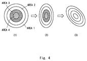
- a concentric circular shape (radius: 1, size ⁇ *1*1) viewed from the front shown in Fig. 4(1) is horizontally inclined, it becomes a concentric circular shape (major axis a, minor axis b, size ⁇ *a*b) shown in Fig. 4(2) . Further, when this concentric circular shape is rotated by 45 degrees, it becomes a concentric circular shape (major axis a, minor axis b, size ⁇ *a*b) shown in Fig. 4(3) .
- the orthogonal projection becomes an elliptic shape and its size ratio becomes constant times (in the example shown in Figs. 4(2) and 4(3) , ab times). Therefore, even if the concentric circular shape of the marker is inclined or enlarged/contracted, the size of each area of the marker also becomes larger/smaller by the constant times. Therefore, its color component ratio is kept unchanged.
- the marker according to the first exemplary embodiment has a concentric circular shape and the code information is expressed by a color component ratio in each area of the code information.
- code information is expressed by a component ratio between "red” and "blue", which are distant from each other in the wavelength range, the effect of the out-of-focus blurring can be reduced even further.
- the concentric circular shape In the concentric circular shape, four areas 1 to 4, for example, are formed from the outer side of the marker toward the center thereof ( Fig. 4(1) ).
- the arrangement of the concentric circular shape is not limited to such an example.
- the number of areas formed in the concentric circular shape may be arbitrarily determined.
- the concentric circular shape may be defined by lengthwise lines.
- the boundaries (including lengthwise lines) between the areas 1 to 4 may be formed, for example, by a green (G) component.
- five states including (R) Red component (an R-component is no less than a threshold R h and a B-component is less than a threshold B h ), (B) Blue component (the R-component is less than the threshold R h and the B-component is no less than the threshold B h ), (R/B) both Read component and Blue component (the R-component is no less than the threshold R h and the B-component is no less than the threshold B h ), (N) neither of Red component and Blue component (the R-component is less than a threshold R L and the B-component is less than a threshold B L ), and (I) indefinite (other than the above-described four states) are defined as predetermined colors.
- the color arrangement unit 14 assigns each of the color frequency information X output from the color information calculation unit 13 to each area of the concentric circular shape. Then, the color arrangement unit 14 uses the assigned information as a size ratio among predetermined colors when the predetermined color is arranged for each area of the marker. For example, the color arrangement unit 14 assigns the color frequency information X of 16-dimensional data output from the color information calculation unit 13 to each of the areas 1 to 4 having the concentric circular shape.
- the 16-dimensional color frequency information X expresses, in each of the areas 1 to 4, a distribution ratio (or arrangement ratio) among (R), (B), (R/B), (N) and (I) when (R), (B), (R/B), (N) and (I) are distributed (or arranged).
- the color arrangement unit 14 assigns first to fourth dimension data to the area 1, assigns fifth to eighth dimension data to the area 2, assigns ninth to twelfth dimension data to the area 3, and assigns 13th to 16th dimension data to the area 4.
- the method for assigning the color frequency information to each area is not limited to the above-described method.
- the total number of pixels in the area 3 is represented by "P3".
- the number of (R) pixels distributed to the area 3 is expressed as "P3*a/(a+b+c+d+e)”.
- the number of (B) pixels is expressed as "P3*b/(a+b+c+d+e)".
- the number of (R/B) pixels is expressed as "P3*c/(a+b+c+d+e)".
- the number of (N) pixels is expressed as "P3*d/(a+b+c+d+e)”.
- the number of (I) pixels is expressed as "P3*e/(a+b+c+d+e)”.
- the total number of pixels in the area 3 is represented by "P4".
- the number of (R) pixels distributed to the area 4 is expressed as "P4*f/(f+g+h+i)".
- the number of (B) pixels is expressed as "P4*g/(f+g+h+i)”.
- the number of (R/B) pixels is expressed as "P4*h/(f+g+h+i)”.
- the number of (N) pixels is expressed as "P4*i/(f+g+h+i)".
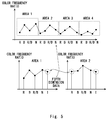
- Fig. 5 is a color histogram showing a color frequency ratio (pixel number ratio) of (R), (B), (R/B), (N) and (I) when (R), (B), (R/B), (N) and (I) are distributed in each of the areas 1 to 4 based on the 16-dimensional color frequency information X.
- the fifth dimension data is used for both of the areas 1 and 2. Further, it is defined so that the color frequency ratio of (I) in the area 1 is equal to that of (R) in the area 2.
- the color arrangement unit 14 generates a marker according to the above-described numbers of pixels of (R), (B), (R/B), (N) and (I) set for each of the areas 1 to 4.
- Fig. 6 is a flowchart showing a marker generation method according to the first exemplary embodiment.
- the code acquisition unit 11 of the marker generation apparatus 10 acquires N-bit code information and outputs the acquired code information to the autocorrelation unit 12 (step S101).
- the autocorrelation unit 12 multiplies each bit value of the code information output from the code acquisition unit 11 by an M-sequence matrix respectively by using the above-shown Expression (1) and outputs the multiplication result obtained by the multiplication to the color information calculation unit 13 (step S102).
- the color information calculation unit 13 calculates color frequency information X of the eventual marker by adding up the multiplication result (color frequency information X i ) output from the autocorrelation unit 12 by using the above-shown Expression (2) and outputs the calculated color frequency information X to the color arrangement unit 14 (step S103).
- the color arrangement unit 14 performs a color arrangement for each circular area of the marker based on the color frequency information calculated by the color information calculation unit 13 (step S104).
- N-bit code information is acquired; each bit value of the code information is multiplied by an M-sequence matrix respectively; the multiplication results (color frequency information) are added up; color frequency information X of the marker is calculated; and a color arrangement is performed for each circular area of the marker based on the calculated color frequency information.
- each bit of the code information is expressed by using the entire area of the marker image, thus making it possible to reduce the decrease in the accuracy of the code information due to noises such as out-of-focus blurring.
- the code information of the marker can be recognized with high accuracy.
- Fig. 7 is a block diagram showing a general system configuration of a marker recognition apparatus according to the first exemplary embodiment.
- the marker recognition apparatus 20 according to the first exemplary embodiment recognizes code information contained in a marker generated by the above-described marker generation apparatus 10.
- the marker recognition apparatus 20 includes an image acquisition unit 21 that acquires an image of a marker (marker image), an area recognition unit 22 that recognizes each area of the marker image, a color information calculation unit 23 that calculates color frequency information, and a code information calculation unit 24 that calculates the code information of the marker.
- the image acquisition unit 21 is a specific example of the image acquisition means.
- the image acquisition unit 21 shoots a marker by using a camera 211 and acquires its marker image.
- the image acquisition unit 21 outputs the acquired marker image to the area recognition unit 22.
- the area recognition unit 22 is a specific example of the recognition means.
- the area recognition unit 22 recognizes each area of the marker image output from the image acquisition unit 21. For example, the area recognition unit 22 detects boundaries between the areas 1 to 4 having a concentric circular shape based on the marker image output from the image acquisition unit 21, and thereby recognizes the areas 1 to 4.
- the area recognition unit 22 outputs the recognized recognition result of each area to the color information calculation unit 23.
- the color information calculation unit 23 is a specific example of the color information calculation means.
- the color information calculation unit 23 calculates color frequency information (color information) X based on the recognition result of each area output from the area recognition unit 22.
- the color information calculation unit 23 calculates 16-dimensional data X1 to X16 indicating the component ratio (such as pixel number ratio) of (R), (B), (R/B), (N) and (I) in each of the areas 1 to 4,.
- the color information calculation unit 23 calculates X'1 to X'16 (color frequency information) for which an adjustment to the composition ratio between the areas 1 to 4 has been made. Note that the sizes of the areas 1 to 4 differ from one another. Therefore, for example, the color information calculation unit 23 calculates their respective adjustment values B21 (adjustment between the areas 1 and 2), B32 (adjustment between the areas 2 and 3), and B43 (adjustment between the areas 3 and 4).
- the color information calculation unit 23 calculates X'1 to X'16 based on these adjustment values B21, B32 and B43.
- the 13th dimension data corresponds to (I) in the area 3 and corresponds to (R) in the area 4.
- the adjustment values B21 and B32 can be calculated in a similar manner to that for the above-described adjustment value B43.
- the color information calculation unit 23 calculates each of the 16-dimensional data X'1 to X'16 (color frequency information X) based on the 16-dimensional data X1 to X16 and the above-described calculated adjustment values B21, B32 and B43 by using the below-shown Expression.
- the color information calculation unit 23 outputs the above-described calculated color frequency information X to the code information calculation unit 24.
- the code information calculation unit 24 is a specific example of the color information calculation means.
- the code information calculation unit 24 calculates the code information S of the marker by multiplying the color frequency information X output from the color information calculation unit 23 by a transposed matrix (detection matrix) W T of the M-sequence matrix.
- the code information calculation unit 24 calculates the code information S of the marker based on the color frequency information X output from the color information calculation unit 23 by using the below-shown Expression (3).
- S W T X
- n-bit code information (e.g., 16-bit code information) can be expressed.
- Fig. 8 is a flowchart showing the marker recognition method according to the first exemplary embodiment.
- the image acquisition unit 21 of the marker recognition apparatus 20 shoots a marker by using the camera 211, acquires its marker image, and outputs the acquired marker image to the area recognition unit 22 (step S201).
- the area recognition unit 22 recognizes each area of the marker image output from the image acquisition unit 21 and outputs the recognition result to the color information calculation unit 23 (step S202).
- the color information calculation unit 23 calculates color frequency information X based on the recognition result of each area output from the area recognition unit 22 and outputs the calculated color frequency information X to the code information calculation unit 24 (step S203).
- the code information calculation unit 24 calculates the code information S of the marker based on the color frequency information X output from the color information calculation unit 23 by using the above-shown Expression (3) (step S204).
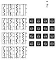
- Fig. 9 shows values of color frequency information X i each corresponding to a respective bit of code information and their marker images. Note that each of the color frequency information X i is an M-sequence itself (upper part in Fig. 9 ).
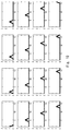
- Fig. 10 shows results of a series of processes in which: a marker image is read; intermediate code is extracted from color frequency information; and code information is recognized by the marker recognition apparatus. As shown in Fig. 10 , it can be understood that corresponding bits are correctly set (set to one) in every data.
- Fig. 11A shows graphs showing a result when the values of the even bits, i.e., 2nd, 4the, 6th, 8th, 10th, 12th and 14th bits are set to one.
- the left graph shows color frequency information X
- the right graph of Fig. 11A it can be confirmed that the aforementioned even bits are correctly set and code information can be expressed. That is, it can be confirmed that one bit is expressed by the whole marker image and the code information can be embedded in the marker.
- Figs. 11 (B) and 11(C) show recognition results when white noises are added in the marker image.
- uniform random numbers are generated for errors.
- the errors are changed by ⁇ 10.24 by the RGB value in Fig. 11(B) , and they are changed by ⁇ 25.6 by the RGB value in Fig. 11(C) .
- the aforementioned even bits are correctly set. That is, it can be confirmed that the marker recognition apparatus 20 can correctly recognize the code information.
- a marker recognition apparatus 30 includes, in addition to the above-described configuration, a learning section 25 that learns a transposed matrix W T (hereinafter called a "detection matrix W") of the M-sequence matrix by an ICA (Independent Component Analysis) by using a marker image containing a noise ( Fig. 12 ).
- the learning section 25 is a specific example of the learning means.
- the learning section 25 generates, for example, a plurality of (out-of-focus) marker images containing noises by rotating the marker image or superimposing a Gaussian function ( ⁇ ) on the marker image.
- Out-of-focus blurring could occur in the marker image depending the distance to the marker and/or the position of the marker.
- the marker recognition apparatus 30 learns a detection matrix W by the ICA by using out-of-focus marker images. This can improve the detection accuracy by the detection matrix W.
- the ICA automatically extracts only the component that is independent of the input data. For example, by using Super Gaussian distribution as the probability density function set for the ICA, the detection matrix W can be learned in such a manner that one value of the output data becomes higher and the other values become lower.
- each bit value is expressed by a feature pattern of the whole marker image.
- the feature pattern of the whole marker image is learned by the ICA.
- the detection matrix W when the number of components of the input data is equal to or greater than a certain number, the values of the corresponding bits ((B) and (C)) are output as high values and the value of the non-corresponding bit (A) is output as a low value even when the input data contains noises (a defective pixel or the like).
- the learning section 25 generates the detection matrix W that is robust against noise images.
- each bit value is expressed by a feature pattern of the whole marker image.
- the ICA the use of the ICA for the detection matrix enables the detection of the presence/absence of components of a feature pattern corresponding to each bit. This is because the components of a feature pattern corresponding to each bit are learned as independent components. Therefore, it is possible to detect the presence/absence of components of a feature pattern corresponding to each bit even in the state where each bit is superimposed.
- the learning section 25 generates a group of out-of-focus marker images (3) by, for example, rotating a marker image acquired by the image acquisition unit 21 in a roll direction, a pitch direction, and yaw direction (1) (Note that the rotation in the yaw direction can be omitted).
- the learning section 25 generates a group of out-of-focus marker images (3) by superimposing a Gaussian function on each of marker images acquired by the image acquisition unit 21 (2).
- the learning section 25 may generate a group of out-of focus marker images (3) by rotating a marker image (1) and then superimposing a Gaussian function on each of the rotated marker images (2).
- the learning section 25 may generate a group of resolution-blurred images by performing down-sampling. Then, the learning section 25 learns a detection matrix W by the ICA as shown below by using the group of out-of-focus images (or the group of resolution-blurred images) (4).
- P represents an initial value of a weighting matrix.
- the learning section 25 assumes that the probability density function of S is Super Gaussian distribution and performs the ICA by a natural gradient method so that the mutual information amount is minimized.
- the same symbols as those for the marker recognition apparatus 20 according to the above-described first exemplary embodiment are assigned to the same components/structures as those of the marker recognition apparatus 20.
- Fig. 15 shows learning results obtained by using the out-of-focus blurring image group.
- the upper part shows a matrix B after the learning (hereinafter expressed as the "post-learning matrix B") and the lower part shows code recognition results (outputs of the code information calculation unit 24) corresponding to the respective bits.
- the post-learning matrix B is deformed by the learning, though maintaining the form of the M-sequence matrix shown in the upper part of Fig. 9 . As shown in the lower part of Fig. 15 , it can be confirmed that each bit can be correctly recognized by using the post-learning matrix B.
- Fig. 16 shows results obtained by evaluations of 900 test data by using the above-described input image patterns.
- the upper-left graph of Fig. 16 shows an output result from the code information calculation unit in a case where ⁇ there is no out-of-focus blurring, and ICA learning is not performed ⁇ and the upper-right graph of Fig. 16 shows an output result in a case where ⁇ there is no out-of-focus blurring, and ICA learning is performed ⁇ .
- the upper-left and upper right graphs of Fig. 16 it can be understood that the bits are correctly recognized in both cases.
- the lower-left graph of Fig. 16 shows an output result from the code information calculation unit in a case where ⁇ there is out-of-focus blurring, and ICA learning is not performed ⁇ and the lower-right graph of Fig. 16 shows an output result in a case where ⁇ there is out-of-focus blurring, and ICA learning is performed ⁇ .
- the recognitions of eighth and ninth bits are failed.
- the recognitions of eighth and ninth bits are succeeded (broken line in the figure).
- the test data is correctly recognized 630 times out of 900 types of test data.
- the ICA learning can increase the correct recognition to 748 times (increase in success rate by 13%). Based on the above-described experiment results, it can be understood that the learning of the detection matrix by the ICA by using marker images containing noises improve the accuracy of recognition of the marker code information.
- the marker recognition apparatus 30 includes the learning section 25 and learns detection matrixes by the ICA in the above-described exemplary embodiment, the present invention is not limited to such a configuration.
- the marker generation apparatus 10 may further include a learning unit and learn generator matrixes by the ICA.
- the marker generation apparatus 10 may calculate a transposed matrix of the detection matrix, for which learning is already performed, in the marker recognition apparatus 30 and use the transposed matrix as the generator matrix.
- the color information calculation unit 13 calculates color frequency information (a ratio among predetermined colors), which is used for performing a color arrangement for each area of the marker, by adding up multiplication results obtained by the autocorrelation unit 12, the present invention is not limited to such a configuration.
- the color information calculation unit 13 may calculate brightness information of predetermined colors (the level of each component) such as a red component and a blue component used for the color arrangement for each area of the marker by adding up multiplication results obtained by the autocorrelation unit 12.
- the color arrangement unit 14 performs a color arrangement for each area of the marker based on the brightness information calculated by the color information calculation unit 13.
- the color information calculation unit 13 may calculate binary information for white and black for the color arrangement for each area of the marker by adding up multiplication results obtained by the autocorrelation unit 12.
- the color arrangement unit 14 performs a color arrangement for each area of the marker based on the binary information calculated by the color information calculation unit 13.
- the shape of the marker is not limited to the circular shape.
- the marker may have a polygonal shape such as a square shape, or have an axial symmetry or a point symmetry shape.
- the processes shown in Figs. 6 and 8 can be implemented by causing a CPU to execute a computer program.
- the program can be stored in various types of non-transitory computer readable media and thereby supplied to computers.
- the non-transitory computer readable media includes various types of tangible storage media. Examples of the non-transitory computer readable media include a magnetic recording medium (such as a flexible disk, a magnetic tape, and a hard disk drive), a magneto-optic recording medium (such as a magneto-optic disk), a CD-ROM (Read Only Memory), a CD-R, and a CD-R/W, and a semiconductor memory (such as a mask ROM, a PROM (Programmable ROM), an EPROM (Erasable PROM), a flash ROM, and a RAM (Random Access Memory)).
- a magnetic recording medium such as a flexible disk, a magnetic tape, and a hard disk drive
- a magneto-optic recording medium such as a magneto-optic disk
- CD-ROM Read Only Memory
- CD-R Compact Only Memory
- CD-R/W and
- the program can be supplied to computers by using various types of transitory computer readable media.
- Examples of the transitory computer readable media include an electrical signal, an optical signal, and an electromagnetic wave.
- the transitory computer readable media can be used to supply programs to computer through a wire communication path such as an electrical wire and an optical fiber, or wireless communication path.
- a marker generation apparatus includes code acquisition means for acquiring N-bit code information (N is a natural number no less than two) for superimposing the code information on a marker defined in a plurality of areas, multiplication means for multiplying each bit value of the code information acquired by the code acquisition means by an M-sequence matrix respectively, color information calculation means for calculating color information by adding up multiplication results obtained by the multiplication means, the color information being used for performing a color arrangement for each area of the marker, and color arrangement means for performing a color arrangement for each area of the marker based on the color information calculated by the color information calculation means.
Landscapes
- Physics & Mathematics (AREA)
- Engineering & Computer Science (AREA)
- General Physics & Mathematics (AREA)
- Theoretical Computer Science (AREA)
- Electromagnetism (AREA)
- Health & Medical Sciences (AREA)
- General Health & Medical Sciences (AREA)
- Toxicology (AREA)
- Artificial Intelligence (AREA)
- Computer Vision & Pattern Recognition (AREA)
- Image Analysis (AREA)
- Image Processing (AREA)
Abstract
Description
- The present invention relates to a marker generation apparatus, a marker recognition apparatus, a marker generation method, a marker recognition method, and a program for generating or recognizing a marker attached or marked on an item.
- A 2D (two-dimensional) code reader that reads a 2D code such as a QR code (Registered Trademark) has been known (see, for example, Japanese Unexamined Patent Application Publication No.
2009-295145 - It should be noted that a marker such as a 2D code contains code information. Further, each pixel in a marker image expresses 1-bit value of code information contained in the marker image. Therefore, for example, when there is a missing (or defective) pixel in the marker image due to noises such as out-of-focus blurring, there is a possibility that the accuracy of recognition of the code information of the marker image may be lowered.
- The present invention has been made to solve the above-described problem and an object thereof is to provide a marker generation apparatus, a marker recognition apparatus, a marker generation method, a marker recognition method, and a program capable of recognizing code information of a marker with high accuracy.
- To achieve the above-described object, a first exemplary aspect of the present invention is a marker generation apparatus including: code acquisition means for acquiring N-bit code information (N is a natural number no less than two) for superimposing the code information on a marker defined in a plurality of areas; multiplication means for multiplying each bit value of the code information acquired by the code acquisition means by an M-sequence matrix respectively; color information calculation means for calculating color information by adding up multiplication results obtained by the multiplication means, the color information being used for performing a color arrangement for each area of the marker; and color arrangement means for performing a color arrangement for each area of the marker based on the color information calculated by the color information calculation means.
- In this aspect, the color information may be information indicating a ratio among a plurality of predetermined colors for arranging each of the plurality of predetermined colors for each area of the marker, the plurality of predetermined colors being defined in advance.
- In this aspect, the color arrangement means may perform the color arrangement by assigning color information calculated by the color information calculation means to each area of the marker, respectively, and using the assigned information as a size ratio among the predetermined colors when the predetermined color is arranged for each area of the marker.
- In this aspect, the marker may have a concentric circular shape and each area of the marker may be defined by a concentric circular boundary.
- In this aspect, the marker generation apparatus may further include learning means for learning the M-sequence matrix by an ICA (Independent Component Analysis) by using a marker image containing a noise, and the multiplication means may multiply each bit value of the code information acquired by the code acquisition means by an M-sequence matrix, respectively, learned by the learning means.
- To achieve the above-described object, another exemplary aspect of the present invention may be a marker recognition apparatus that recognizes code information of a marker generated by the above-described marker generation apparatus.
- In this aspect, the marker recognition apparatus may include: image acquisition means for acquiring an image of the marker; recognition means for recognizing each area of the image of the marker acquired by image acquisition means; color information calculation means for calculating the color information based on each area recognized by the recognition means; and code information calculation means for calculating the code information by multiplying color information calculated by the color information calculation means by a transposed matrix of the M-sequence matrix.
- In this aspect, the marker recognition apparatus may further include learning means for learning the transposed matrix by an ICA (Independent Component Analysis) by using a marker image containing a noise, and the code information calculation means may calculate the code information by multiplying the color information calculated by the color information calculation means by the transposed matrix learned by the learning means.
- To achieve the above-described object, another exemplary aspect of the present invention is a marker generation method including: a step of acquiring N-bit code information (N is a natural number no less than two) for superimposing the code information on a marker defined in a plurality of areas; a step of multiplying each bit value of the acquired code information by an M-sequence matrix respectively; a step of calculating color information by adding up multiplication results obtained by the multiplication, the color information being used for performing a color arrangement for each area of the marker; and a step of performing a color arrangement for each area of the marker based on the calculated color information.
- To achieve the above-described object, another exemplary aspect of the present invention may be a marker recognition method for recognizing code information of a marker generated by the above-described marker generation method.
- In this aspect, the marker recognition method may include: a step of acquiring an image of the marker; a step of recognizing each area of the image of the acquired marker; a step of calculating the color information based on each of the recognized areas; and a step of calculating the code information by multiplying the calculated color information by a transposed matrix of the M-sequence matrix.
- To achieve the above-described object, another exemplary aspect of the present invention may be a program for causing a computer to execute: a process of acquiring N-bit code information (N is a natural number no less than two) for superimposing the code information on a marker defined in a plurality of areas; a process of multiplying each bit value of the acquired code information by an M-sequence matrix respectively; a process of calculating color information by adding up multiplication results obtained by the multiplication, the color information being used for performing a color arrangement for each area of the marker; and a process of performing a color arrangement for each area of the marker based on the calculated color information.
- According to the present invention, it is possible to provide a marker generation apparatus, a marker recognition apparatus, a marker generation method, a marker recognition method, and a program capable of recognizing code information of a marker with high accuracy.
- The above and other objects, features and advantages of the present invention will become more fully understood from the detailed description given hereinbelow and the accompanying drawings which are given by way of illustration only, and thus are not to be considered as limiting the present invention.
-
-
Fig. 1 shows figures expressing each bit value by feature patterns of the whole marker images; -
Fig. 2 shows figures expressing one bit values by a plurality of N-dimensional waveforms; -
Fig. 3 is a block diagram showing a general system configuration of a marker generation apparatus according to a first exemplary embodiment of the present invention; -
Fig. 4 shows an example of a marker having a concentric circular shape; -
Fig. 5 shows an example of a color histogram showing a color frequency ratio among (R), (B), (R/B), (N) and (I); -
Fig. 6 is a flowchart showing a marker generation method according to the first exemplary embodiment of the present invention; -
Fig. 7 is a block diagram showing a general system configuration of a marker recognition apparatus according to the first exemplary embodiment of the present invention; -
Fig. 8 is a flowchart showing a marker recognition method according to the first exemplary embodiment of the present invention; -
Fig. 9 shows color frequency information values each corresponding to a respective one of bits of code information and their marker images; -
Fig. 10 shows results of code information recognized by a marker recognition apparatus; -
Fig. 11A shows graphs showing an output result when an even bit value is one; -
Fig. 11B shows graphs showing an output result when an even bit value is one; -
Fig. 11C shows graphs showing an output result when an even bit value is one; -
Fig. 12 is a block diagram showing a general system configuration of a marker recognition apparatus according to a second exemplary embodiment of the present invention; -
Fig. 13 shows figures for explaining a detection matrix after ICA learning; -
Fig. 14 shows figures for explaining a method for learning a detection matrix W by an ICA; -
Fig. 15 shows learning results by an out-of-focus blurring image group; and -
Fig. 16 shows results obtained by evaluations of 900 test data by using input image patterns. - Exemplary embodiments according to the present invention are explained hereinafter with reference to the drawings.
- For example, a marker is attached or marked on an item that its robot operates. The robot can recognize the position, the posture, the distance, and so on of the item by recognizing the positon of the marker. Further, when the marker contains code information, the robot can recognize the code information at the same time that it recognizes the position and size of the marker. A marker recognition apparatus according to a first exemplary embodiment of the present invention generates code information that is contained (i.e., incorporated) in a marker like the one described above.
- It should be noted that in the past, for example, each pixel of a marker image expresses 1-bit value. Therefore, there is a problem that when there is a missing pixel (or defective pixel) (hereinafter simply referred to as a "defective pixel") in a marker image due to noises such as out-of-focus blurring, the accuracy of the code information of the marker image could be lowered.
- In contrast to this, the marker recognition apparatus according to the first exemplary embodiment expresses each bit value of code information by a feature pattern of the whole marker image. Therefore, even when a defective pixel or the like occurs in the marker image, the marker recognition apparatus can lower the effect of the defective pixel. Therefore, the code information of the marker can be recognized with higher accuracy.
- For example, as shown in
Fig. 1 , the marker recognition apparatus generates a marker image (c) expressing a 2-bit value (11) by superimposing a marker image (b) expressing a 1-bit value (10) on another marker image (c) expressing a 1-bit value (01). In this case, even if a defective pixel occurs in the marker image (a), it is possible to generate a marker image that is not affected by this defective pixel by restoring it by using the other information. - More specifically, as shown in
Fig. 2 , the two 1-bit values are expressed by a plurality of (i.e., two) N-dimensional (e.g., 16-dimensional) waveforms ((A) and (B)), respectively. Information for expressing the marker (e.g., a color histogram (color component ratio) as shown inFig. 2(C) ) is generated by superimposing these waveforms on each other. Then, a color arrangement is performed for the marker based on the generated information. -
Fig. 3 is a block diagram showing a general system configuration of the marker generation apparatus according to the first exemplary embodiment. Themarker generation apparatus 10 according to the first exemplary embodiment includes acode acquisition unit 11 that acquires N-bit code information (N is a natural number no less than two), anautocorrelation unit 12 that multiplies each bit value of the acquired code information by a matrix of a M-sequence (hereinafter called an "M-sequence matrix") respectively, a colorinformation calculation unit 13 that calculates color frequency information used for performing a color arrangement for each area of the marker, and acolor arrangement unit 14 that performs a color arrangement for each area of the marker. - Each of the
marker generation apparatus 10 and a marker recognition apparatus 20 (which will described later) is constructed, for example, by hardware by mainly using a microcomputer including a CPU (Central Processing Unit) that performs arithmetic processing and so on, a memory including a ROM (Read Only Memory) and/or a RAM (Random Access Memory) in which an operation program, a control program, and so on executed by the CPU are stored, an interface unit (I/F) that externally receives/outputs signals, and so on. The CPU, the memory, and the interface unit are connected to each other through a data bus and the like. - The
code acquisition unit 11 is a specific example of the code acquisition means. Thecode acquisition unit 11 acquires N-bit code information (e.g., information composed of zero and one) for superimposing it on a marker defined in a plurality of areas. Thecode acquisition unit 11 outputs the acquired code information to theautocorrelation unit 12. - The
autocorrelation unit 12 is a specific example of the multiplication means. Theautocorrelation unit 12 multiplies each bit value of the code information acquired by thecode acquisition unit 11 by an M-sequence matrix respectively. For example, theautocorrelation unit 12 multiplies each bit value of the code information output from thecode acquisition unit 11 by the M-sequence matrix respectively by using the below-shown Expression (1).
- Note that in the above-shown expression, S is code information output from the
code acquisition unit 11 and is, for example, zero or one. W is a generator matrix of an M-sequence (Maximum-length shift-register sequence). This generator matrix W is composed of, for example, an M-sequence of a spread code. This M-sequence has a characteristic by which the autocorrelation is high and the cross-correlation is low. Therefore, it is possible to improve the noise tolerance by multiplying each bit value of the code information by the M-sequence matrix respectively and thereby increase the autocorrelation for each bit value of the code information. That is, each bit value of the code information is expressed by a feature pattern of the whole marker image. - Here, the generator matrix W is expressed by an orthogonal M-sequence P in order to maximize the inter-code distance. The M-sequence uses four-dimensional primitive polynomial (a4+a+1) and 15 (=24-1) code sequences of {1, -1} are obtained. The orthogonal M-sequence is obtained by using {-1} as the value for i=16 for P*i and Pi*. Note that the generator matrix W can be formed by an arbitrary M-sequence having a characteristic by which the autocorrelation is high and the cross-correlation is low. The
autocorrelation unit 12 outputs the multiplication result obtained by the above-described multiplication to the colorinformation calculation unit 13. - The color
information calculation unit 13 is a specific example of the color information calculation means. The colorinformation calculation unit 13 calculates color frequency information (an example of color information), which is used for performing a color arrangement for each area of the marker, by adding up the multiplication results obtained by theautocorrelation unit 12. This color frequency information is, for example, information indicating a ratio among a plurality of predetermined colors, which are defined in advance, for arranging each of the plurality of predetermined colors for each area of the marker. - The color
information calculation unit 13 calculates, for example, color frequency information X of the eventual marker by adding up color frequency information Xi of each of 16-dimensional bits by using the below-shown Expression (2).
[Expression 1]
- The color
information calculation unit 13 outputs the calculated color frequency information X to thecolor arrangement unit 14. - The
color arrangement unit 14 is a specific example of the color arrangement means. Thecolor arrangement unit 14 performs a color arrangement for each area of the marker based on the color frequency information X calculated by the colorinformation calculation unit 13. - Note that, for example, since a robot or the like makes complicated movements and observes a marker of an item from various distances and from various directions, how the marker is observed widely changes. Therefore, there is a need for code information that is independent of the position of the marker (i.e., irrespective of how the marker is observed depending on the direction and the scale) on which the code information is superimposed.
- To cope with this, the marker according to the first exemplary embodiment has, for example, a layered (ring-shaped) circular shape (hereinafter called a "concentric circular shape"). Each area in the concentric circular shape is defined by a concentric circular boundary. The
color arrangement unit 14 determines a color component ratio (color arrangement) in each area (each layer) of the concentric circular shape. - Note that the circular shape is robust against rotations and inclinations. Therefore, the marker is formed in a circular shape and a color arrangement is performed for each area having a circular shape according to the color frequency information indicating the code information. As a result, it is possible to provide code information that is independent of the position of the marker (i.e., irrespective of how the marker is observed depending on the direction and the scale) on which the code information is superimposed.
- For example, when a concentric circular shape (radius: 1, size π*1*1) viewed from the front shown in
Fig. 4(1) is horizontally inclined, it becomes a concentric circular shape (major axis a, minor axis b, size π*a*b) shown inFig. 4(2) . Further, when this concentric circular shape is rotated by 45 degrees, it becomes a concentric circular shape (major axis a, minor axis b, size π*a*b) shown inFig. 4(3) . As described above, when the concentric circular shape is inclined, the orthogonal projection becomes an elliptic shape and its size ratio becomes constant times (in the example shown inFigs. 4(2) and 4(3) , ab times). Therefore, even if the concentric circular shape of the marker is inclined or enlarged/contracted, the size of each area of the marker also becomes larger/smaller by the constant times. Therefore, its color component ratio is kept unchanged. - Therefore, the marker according to the first exemplary embodiment has a concentric circular shape and the code information is expressed by a color component ratio in each area of the code information. This makes it possible to encode code information that is independent of the position of the marker in the marker. For example, it is possible to express code information that is hardly affected by environment light and the spectroscopic characteristic of the marker. In particular, when code information is expressed by a component ratio between "red" and "blue", which are distant from each other in the wavelength range, the effect of the out-of-focus blurring can be reduced even further.
- In the concentric circular shape, four
areas 1 to 4, for example, are formed from the outer side of the marker toward the center thereof (Fig. 4(1) ). However, the arrangement of the concentric circular shape is not limited to such an example. The number of areas formed in the concentric circular shape may be arbitrarily determined. Further, the concentric circular shape may be defined by lengthwise lines. The boundaries (including lengthwise lines) between theareas 1 to 4 may be formed, for example, by a green (G) component. - For example, for each of the
areas 1 to 3, five states including (R) Red component (an R-component is no less than a threshold Rh and a B-component is less than a threshold Bh), (B) Blue component (the R-component is less than the threshold Rh and the B-component is no less than the threshold Bh), (R/B) both Read component and Blue component (the R-component is no less than the threshold Rh and the B-component is no less than the threshold Bh), (N) neither of Red component and Blue component (the R-component is less than a threshold RL and the B-component is less than a threshold BL), and (I) indefinite (other than the above-described four states) are defined as predetermined colors. For thearea 4, four states including the above-described (R), (B), (R/B), and (N) states are defined. Note that (I) indefinite is defined to obtain the consistency of the output ratio among the areas. The above-described thresholds are defined, for example, as follows: Rh=120, Bh=117, and RL=BL=50. - The
color arrangement unit 14 assigns each of the color frequency information X output from the colorinformation calculation unit 13 to each area of the concentric circular shape. Then, thecolor arrangement unit 14 uses the assigned information as a size ratio among predetermined colors when the predetermined color is arranged for each area of the marker. For example, thecolor arrangement unit 14 assigns the color frequency information X of 16-dimensional data output from the colorinformation calculation unit 13 to each of theareas 1 to 4 having the concentric circular shape. The 16-dimensional color frequency information X expresses, in each of theareas 1 to 4, a distribution ratio (or arrangement ratio) among (R), (B), (R/B), (N) and (I) when (R), (B), (R/B), (N) and (I) are distributed (or arranged). - For example, the
color arrangement unit 14 assigns first to fourth dimension data to thearea 1, assigns fifth to eighth dimension data to thearea 2, assigns ninth to twelfth dimension data to thearea 3, and assigns 13th to 16th dimension data to thearea 4. Note that the method for assigning the color frequency information to each area is not limited to the above-described method. - A method for performing a color arrangement for the
area 3 is explained hereinafter. Here, the ninth to 13th dimension data are expressed as follows: (ninth dimension data):(tenth dimension data):(eleventh dimension data):(twelfth dimension data):(13th dimension data) = a:b:c:d:e. The total number of pixels in thearea 3 is represented by "P3". In this case, the number of (R) pixels distributed to thearea 3 is expressed as "P3*a/(a+b+c+d+e)". The number of (B) pixels is expressed as "P3*b/(a+b+c+d+e)". The number of (R/B) pixels is expressed as "P3*c/(a+b+c+d+e)". The number of (N) pixels is expressed as "P3*d/(a+b+c+d+e)". Further, the number of (I) pixels is expressed as "P3*e/(a+b+c+d+e)". - For the
area 4, the 13th to 16th dimension data are expressed as follows: (13th dimension data):(14th dimension data):(15th dimension data):(16th dimension data) = f:g:h:i. The total number of pixels in thearea 3 is represented by "P4". In this case, the number of (R) pixels distributed to thearea 4 is expressed as "P4*f/(f+g+h+i)". The number of (B) pixels is expressed as "P4*g/(f+g+h+i)". The number of (R/B) pixels is expressed as "P4*h/(f+g+h+i)". The number of (N) pixels is expressed as "P4*i/(f+g+h+i)". - Note that as shown above, only the (13th dimension data) is used for both of the
areas areas areas areas 1 to 4 can be absorbed, thus making it possible to achieve the consistency even when the distribution ratio in each of theareas 1 to 4 is observed in the whole 16-dimensional data.Fig. 5 is a color histogram showing a color frequency ratio (pixel number ratio) of (R), (B), (R/B), (N) and (I) when (R), (B), (R/B), (N) and (I) are distributed in each of theareas 1 to 4 based on the 16-dimensional color frequency information X. For example, as shown inFig. 5 , the fifth dimension data is used for both of theareas area 1 is equal to that of (R) in thearea 2. - Lastly, the
color arrangement unit 14 generates a marker according to the above-described numbers of pixels of (R), (B), (R/B), (N) and (I) set for each of theareas 1 to 4. -
Fig. 6 is a flowchart showing a marker generation method according to the first exemplary embodiment. Thecode acquisition unit 11 of themarker generation apparatus 10 acquires N-bit code information and outputs the acquired code information to the autocorrelation unit 12 (step S101). Theautocorrelation unit 12 multiplies each bit value of the code information output from thecode acquisition unit 11 by an M-sequence matrix respectively by using the above-shown Expression (1) and outputs the multiplication result obtained by the multiplication to the color information calculation unit 13 (step S102). - The color
information calculation unit 13 calculates color frequency information X of the eventual marker by adding up the multiplication result (color frequency information Xi) output from theautocorrelation unit 12 by using the above-shown Expression (2) and outputs the calculated color frequency information X to the color arrangement unit 14 (step S103). Thecolor arrangement unit 14 performs a color arrangement for each circular area of the marker based on the color frequency information calculated by the color information calculation unit 13 (step S104). - As stated above, in the first exemplary embodiment: N-bit code information is acquired; each bit value of the code information is multiplied by an M-sequence matrix respectively; the multiplication results (color frequency information) are added up; color frequency information X of the marker is calculated; and a color arrangement is performed for each circular area of the marker based on the calculated color frequency information. In this way, each bit of the code information is expressed by using the entire area of the marker image, thus making it possible to reduce the decrease in the accuracy of the code information due to noises such as out-of-focus blurring. As a result, the code information of the marker can be recognized with high accuracy.
-
Fig. 7 is a block diagram showing a general system configuration of a marker recognition apparatus according to the first exemplary embodiment. Themarker recognition apparatus 20 according to the first exemplary embodiment recognizes code information contained in a marker generated by the above-describedmarker generation apparatus 10. - The
marker recognition apparatus 20 according to the first exemplary embodiment includes animage acquisition unit 21 that acquires an image of a marker (marker image), anarea recognition unit 22 that recognizes each area of the marker image, a colorinformation calculation unit 23 that calculates color frequency information, and a codeinformation calculation unit 24 that calculates the code information of the marker. - The
image acquisition unit 21 is a specific example of the image acquisition means. Theimage acquisition unit 21 shoots a marker by using acamera 211 and acquires its marker image. Theimage acquisition unit 21 outputs the acquired marker image to thearea recognition unit 22. - The
area recognition unit 22 is a specific example of the recognition means. Thearea recognition unit 22 recognizes each area of the marker image output from theimage acquisition unit 21. For example, thearea recognition unit 22 detects boundaries between theareas 1 to 4 having a concentric circular shape based on the marker image output from theimage acquisition unit 21, and thereby recognizes theareas 1 to 4. Thearea recognition unit 22 outputs the recognized recognition result of each area to the colorinformation calculation unit 23. - The color
information calculation unit 23 is a specific example of the color information calculation means. The colorinformation calculation unit 23 calculates color frequency information (color information) X based on the recognition result of each area output from thearea recognition unit 22. - For example, the color
information calculation unit 23 calculates 16-dimensional data X1 to X16 indicating the component ratio (such as pixel number ratio) of (R), (B), (R/B), (N) and (I) in each of theareas 1 to 4,. Next, the colorinformation calculation unit 23 calculates X'1 to X'16 (color frequency information) for which an adjustment to the composition ratio between theareas 1 to 4 has been made. Note that the sizes of theareas 1 to 4 differ from one another. Therefore, for example, the colorinformation calculation unit 23 calculates their respective adjustment values B21 (adjustment between theareas 1 and 2), B32 (adjustment between theareas 2 and 3), and B43 (adjustment between theareas 3 and 4). Then, the colorinformation calculation unit 23 calculates X'1 to X'16 based on these adjustment values B21, B32 and B43. For example, the 13th dimension data corresponds to (I) in thearea 3 and corresponds to (R) in thearea 4. The adjustment value B43 can be calculated by Expression "B43 = (P3-(X9+X10+X11+X12))/X13". Meanwhile, if the value of the corresponding 13th dimension data is zero, there is no color. Therefore, the above-described associating cannot be made. In such a case, the adjustment value B43 is calculated by Expression "B43 = P3/(X13+X14+X15+X16)" by using the number of color frequency information and the size ratio. The adjustment values B21 and B32 can be calculated in a similar manner to that for the above-described adjustment value B43. - The color
information calculation unit 23 calculates each of the 16-dimensional data X'1 to X'16 (color frequency information X) based on the 16-dimensional data X1 to X16 and the above-described calculated adjustment values B21, B32 and B43 by using the below-shown Expression. - X'16=X16, X'15=X15, X'14=X14, X'13=X13, X'12=X12*(1/B43), X'11=X11*(1/B43), X'10=X10*(1/B43), X'9=X9*(1/B43), X'8=X8*(1/(B43*B32)), X'7=X7*(1/(B43*B32)), X'6=X6*(1/(B43*B32)), X'5=X5*(1/(B43*B32)), X'4=X4*(1/(B43*B32*B21)), X'3=X3*(1/(B43*B32*B21)), X'2=X2*(1/(B43*B32*B21)), X'1=X1*(1/(B43*B32*B21))
- The color
information calculation unit 23 outputs the above-described calculated color frequency information X to the codeinformation calculation unit 24. - The code
information calculation unit 24 is a specific example of the color information calculation means. The codeinformation calculation unit 24 calculates the code information S of the marker by multiplying the color frequency information X output from the colorinformation calculation unit 23 by a transposed matrix (detection matrix) WT of the M-sequence matrix. For example, the codeinformation calculation unit 24 calculates the code information S of the marker based on the color frequency information X output from the colorinformation calculation unit 23 by using the below-shown Expression (3).
- Here, if Si (i-th dimension value of S) is equal to or higher than a threshold, the i-th bit is set to one. If not so, the i-th bit is set to zero. In this way, n-bit code information (e.g., 16-bit code information) can be expressed.
-
Fig. 8 is a flowchart showing the marker recognition method according to the first exemplary embodiment. Theimage acquisition unit 21 of themarker recognition apparatus 20 shoots a marker by using thecamera 211, acquires its marker image, and outputs the acquired marker image to the area recognition unit 22 (step S201). Thearea recognition unit 22 recognizes each area of the marker image output from theimage acquisition unit 21 and outputs the recognition result to the color information calculation unit 23 (step S202). - The color
information calculation unit 23 calculates color frequency information X based on the recognition result of each area output from thearea recognition unit 22 and outputs the calculated color frequency information X to the code information calculation unit 24 (step S203). The codeinformation calculation unit 24 calculates the code information S of the marker based on the color frequency information X output from the colorinformation calculation unit 23 by using the above-shown Expression (3) (step S204). - Next, whether or not the above-described marker recognition apparatus could recognize code information of a marker generated by the above-described marker generation apparatus was evaluated.
Fig. 9 shows values of color frequency information Xi each corresponding to a respective bit of code information and their marker images. Note that each of the color frequency information Xi is an M-sequence itself (upper part inFig. 9 ). -
Fig. 10 shows results of a series of processes in which: a marker image is read; intermediate code is extracted from color frequency information; and code information is recognized by the marker recognition apparatus. As shown inFig. 10 , it can be understood that corresponding bits are correctly set (set to one) in every data. -
Fig. 11A shows graphs showing a result when the values of the even bits, i.e., 2nd, 4the, 6th, 8th, 10th, 12th and 14th bits are set to one. Note that in each ofFigs. 11A to 11C , the left graph shows color frequency information X and the right graph shows the correlation value output result S (=WTX). As shown in the right graph ofFig. 11A , it can be confirmed that the aforementioned even bits are correctly set and code information can be expressed. That is, it can be confirmed that one bit is expressed by the whole marker image and the code information can be embedded in the marker. - Next, an experiment for examining the tolerance to noises was conducted.
Figs. 11 (B) and11(C) show recognition results when white noises are added in the marker image. In the experiment, uniform random numbers are generated for errors. The errors are changed by ±10.24 by the RGB value inFig. 11(B) , and they are changed by ±25.6 by the RGB value inFig. 11(C) . As a result, in the case ofFig. 11(B) , the aforementioned even bits are correctly set. That is, it can be confirmed that themarker recognition apparatus 20 can correctly recognize the code information. - A marker recognition apparatus 30 according to a second exemplary embodiment of the present invention includes, in addition to the above-described configuration, a
learning section 25 that learns a transposed matrix WT (hereinafter called a "detection matrix W") of the M-sequence matrix by an ICA (Independent Component Analysis) by using a marker image containing a noise (Fig. 12 ). Thelearning section 25 is a specific example of the learning means. Thelearning section 25 generates, for example, a plurality of (out-of-focus) marker images containing noises by rotating the marker image or superimposing a Gaussian function (σ) on the marker image. - Out-of-focus blurring could occur in the marker image depending the distance to the marker and/or the position of the marker. To cope with this, the marker recognition apparatus 30 according to the second exemplary embodiment learns a detection matrix W by the ICA by using out-of-focus marker images. This can improve the detection accuracy by the detection matrix W.
- The ICA automatically extracts only the component that is independent of the input data. For example, by using Super Gaussian distribution as the probability density function set for the ICA, the detection matrix W can be learned in such a manner that one value of the output data becomes higher and the other values become lower.
- In the second exemplary embodiment, each bit value is expressed by a feature pattern of the whole marker image. Then, the feature pattern of the whole marker image is learned by the ICA. This makes it possible to generate a detection matrix W (mapping) so that only the corresponding code outputs a value even when the input data contains noises. For example, as shown in
Fig. 13 , in the detection matrix W, when the number of components of the input data is equal to or greater than a certain number, the values of the corresponding bits ((B) and (C)) are output as high values and the value of the non-corresponding bit (A) is output as a low value even when the input data contains noises (a defective pixel or the like). As described above, thelearning section 25 generates the detection matrix W that is robust against noise images. - Note that it is possible to generate a linear or nonlinear detection matrix (mapping) by using other learning devices (such as an SVM and a neural network). However, their detection matrixes are not ones in which separation is performed in a state where each bit is superimposed (a state where features corresponding to respective bits are mixed). In contrast to this, according to the second exemplary embodiment, each bit value is expressed by a feature pattern of the whole marker image. This enables the leaning of a detection matrix by the ICA. Further, in the second exemplary embodiment, the use of the ICA for the detection matrix enables the detection of the presence/absence of components of a feature pattern corresponding to each bit. This is because the components of a feature pattern corresponding to each bit are learned as independent components. Therefore, it is possible to detect the presence/absence of components of a feature pattern corresponding to each bit even in the state where each bit is superimposed.
- Next, a method for learning a detection matrix by the ICA is explained in detail with reference to
Fig. 14 . Thelearning section 25 generates a group of out-of-focus marker images (3) by, for example, rotating a marker image acquired by theimage acquisition unit 21 in a roll direction, a pitch direction, and yaw direction (1) (Note that the rotation in the yaw direction can be omitted). Alternatively, thelearning section 25 generates a group of out-of-focus marker images (3) by superimposing a Gaussian function on each of marker images acquired by the image acquisition unit 21 (2). Note that thelearning section 25 may generate a group of out-of focus marker images (3) by rotating a marker image (1) and then superimposing a Gaussian function on each of the rotated marker images (2). Further, thelearning section 25 may generate a group of resolution-blurred images by performing down-sampling. Then, thelearning section 25 learns a detection matrix W by the ICA as shown below by using the group of out-of-focus images (or the group of resolution-blurred images) (4). In the following explanation, P represents an initial value of a weighting matrix. - The
learning section 25 assumes that the probability density function of S is Super Gaussian distribution and performs the ICA by a natural gradient method so that the mutual information amount is minimized. - The update formula of the ICA is given by the below-shown Expressions (4) to (6). In the expressions, ε is 0.1 and I represents a unit matrix.
[Expression 2]


- The code
information calculation unit 24 calculates code information S by multiplying the color frequency information X output from the colorinformation calculation unit 23 by the detection matrix BT learned by thelearning section 25 by using the below-shown Expression (7). Note that the colorinformation calculation unit 23 calculates the color frequency information X by using the below-shown Expression (8).
[Expression 3]

- Note that in the marker recognition apparatus 30 according to the second exemplary embodiment, the same symbols as those for the
marker recognition apparatus 20 according to the above-described first exemplary embodiment are assigned to the same components/structures as those of themarker recognition apparatus 20. - Next, an experiment for evaluating the robustness against out-of-focus blurring was conducted to verify the above-described blurring leaning effect by using the ICA. An intermediate code pattern (color frequency information X) of each bit is learned by using a group of out-of-focus marker images (rotations and blurring). For each bit, below-shown 900 marker images are created as learning data. The learning was conducted by using 14,400 types of marker images in total for all of 16 bits. In this experiment, the number of iterations for the learning was 10,000.
Fig. 15 shows learning results obtained by using the out-of-focus blurring image group. InFig. 15 , the upper part shows a matrix B after the learning (hereinafter expressed as the "post-learning matrix B") and the lower part shows code recognition results (outputs of the code information calculation unit 24) corresponding to the respective bits. - As shown in the upper part of
Fig. 15 , the post-learning matrix B is deformed by the learning, though maintaining the form of the M-sequence matrix shown in the upper part ofFig. 9 . As shown in the lower part ofFig. 15 , it can be confirmed that each bit can be correctly recognized by using the post-learning matrix B. - Next, the effect of the out-of-focus blurring learning is examined by using the below-shown input image pattern.
-
- Roll: 0 to 20 degrees at interval of 5 degrees, five patterns
- Pitch: 0 to 20 degrees at interval of 5 degrees, five patterns
- Yaw: 0 to 360 degrees at interval of 30 degrees, 12 patterns
- Gaussian: three patterns of 0, 1.0, and 2.0
- Here, the effect is examined by using a marker in which even
bits Fig. 16 shows results obtained by evaluations of 900 test data by using the above-described input image patterns. The upper-left graph ofFig. 16 shows an output result from the code information calculation unit in a case where {there is no out-of-focus blurring, and ICA learning is not performed} and the upper-right graph ofFig. 16 shows an output result in a case where {there is no out-of-focus blurring, and ICA learning is performed}. As shown in the upper-left and upper right graphs ofFig. 16 , it can be understood that the bits are correctly recognized in both cases. - Meanwhile, the lower-left graph of
Fig. 16 shows an output result from the code information calculation unit in a case where {there is out-of-focus blurring, and ICA learning is not performed} and the lower-right graph ofFig. 16 shows an output result in a case where {there is out-of-focus blurring, and ICA learning is performed}. In the lower-left case, the recognitions of eighth and ninth bits are failed. However, in the lower-right case, it has been seen that the recognitions of eighth and ninth bits are succeeded (broken line in the figure). In the case of performing no ICA learning, the test data is correctly recognized 630 times out of 900 types of test data. In contrast to this, the ICA learning can increase the correct recognition to 748 times (increase in success rate by 13%). Based on the above-described experiment results, it can be understood that the learning of the detection matrix by the ICA by using marker images containing noises improve the accuracy of recognition of the marker code information. - Note that the present invention is not limited to the above-described exemplary embodiments, and various modifications can be made without departing the spirit and scope of the present invention.
- For example, although the marker recognition apparatus 30 includes the
learning section 25 and learns detection matrixes by the ICA in the above-described exemplary embodiment, the present invention is not limited to such a configuration. Themarker generation apparatus 10 may further include a learning unit and learn generator matrixes by the ICA. Alternatively, themarker generation apparatus 10 may calculate a transposed matrix of the detection matrix, for which learning is already performed, in the marker recognition apparatus 30 and use the transposed matrix as the generator matrix. - In the above-described exemplary embodiment, although the color
information calculation unit 13 calculates color frequency information (a ratio among predetermined colors), which is used for performing a color arrangement for each area of the marker, by adding up multiplication results obtained by theautocorrelation unit 12, the present invention is not limited to such a configuration. The colorinformation calculation unit 13 may calculate brightness information of predetermined colors (the level of each component) such as a red component and a blue component used for the color arrangement for each area of the marker by adding up multiplication results obtained by theautocorrelation unit 12. Thecolor arrangement unit 14 performs a color arrangement for each area of the marker based on the brightness information calculated by the colorinformation calculation unit 13. - Further, the color
information calculation unit 13 may calculate binary information for white and black for the color arrangement for each area of the marker by adding up multiplication results obtained by theautocorrelation unit 12. Thecolor arrangement unit 14 performs a color arrangement for each area of the marker based on the binary information calculated by the colorinformation calculation unit 13. - Although the marker has a circular shape in the above-described exemplary embodiment, the shape of the marker is not limited to the circular shape. The marker may have a polygonal shape such as a square shape, or have an axial symmetry or a point symmetry shape.
- Further, in the present invention, the processes shown in
Figs. 6 and8 , for example, can be implemented by causing a CPU to execute a computer program. - The program can be stored in various types of non-transitory computer readable media and thereby supplied to computers. The non-transitory computer readable media includes various types of tangible storage media. Examples of the non-transitory computer readable media include a magnetic recording medium (such as a flexible disk, a magnetic tape, and a hard disk drive), a magneto-optic recording medium (such as a magneto-optic disk), a CD-ROM (Read Only Memory), a CD-R, and a CD-R/W, and a semiconductor memory (such as a mask ROM, a PROM (Programmable ROM), an EPROM (Erasable PROM), a flash ROM, and a RAM (Random Access Memory)).
- Further, the program can be supplied to computers by using various types of transitory computer readable media. Examples of the transitory computer readable media include an electrical signal, an optical signal, and an electromagnetic wave. The transitory computer readable media can be used to supply programs to computer through a wire communication path such as an electrical wire and an optical fiber, or wireless communication path.
- From the invention thus described, it will be obvious that the embodiments of the invention may be varied in many ways. Such variations are not to be regarded as a departure from the spirit and scope of the invention, and all such modifications as would be obvious to one skilled in the art are intended for inclusion within the scope of the following claims.
A marker generation apparatus includes code acquisition means for acquiring N-bit code information (N is a natural number no less than two) for superimposing the code information on a marker defined in a plurality of areas, multiplication means for multiplying each bit value of the code information acquired by the code acquisition means by an M-sequence matrix respectively, color information calculation means for calculating color information by adding up multiplication results obtained by the multiplication means, the color information being used for performing a color arrangement for each area of the marker, and color arrangement means for performing a color arrangement for each area of the marker based on the color information calculated by the color information calculation means.
Claims (12)
- A marker generation apparatus (10) comprising:code acquisition means (11) for acquiring N-bit code information (N is a natural number no less than two) for superimposing the code information on a marker defined in a plurality of areas;multiplication means (12) for multiplying each bit value of the code information acquired by the code acquisition means (11) by an M-sequence matrix respectively;color information calculation means (13) for calculating color information by adding up multiplication results obtained by the multiplication means (12), the color information being used for performing a color arrangement for each area of the marker; andcolor arrangement means (14) for performing a color arrangement for each area of the marker based on the color information calculated by the color information calculation means (13).
- The marker generation apparatus (10) according to Claim 1, wherein the color information is information indicating a ratio among a plurality of predetermined colors for arranging each of the plurality of predetermined colors for each area of the mark.er, the plurality of predetermined colors being defined in advance.
- The marker generation apparatus (10) according to Claim 2, wherein the color arrangement means (14) performs the color arrangement by assigning color information calculated by the color information calculation means (13) to each area of the marker, respectively, and using the assigned information as a size ratio among the predetermined colors when the predetermined color is arranged for each area of the marker.
- The marker generation apparatus (10) according to any one of Claims 1 to 3, wherein the marker has a concentric circular shape and each area of the marker is defined by a concentric circular boundary.
- The marker generation apparatus (10) according to any one of Claims 1 to 4, further comprising learning means for learning the M-sequence matrix by an ICA (Independent Component Analysis) by using a marker image containing a noise, wherein
the multiplication means (12) multiplies each bit value of the code information acquired by the code acquisition means by an M-sequence matrix, respectively, learned by the learning means. - A marker recognition apparatus (20) that recognizes code information of a marker generated by a marker generation apparatus (10) according to any one of Claims 1 to 5.
- The marker recognition apparatus (20) according to Claim 6, comprising:image acquisition means (21) for acquiring an image of the marker;recognition means (22) for recognizing each area of the image of the marker acquired by image acquisition means (21);color information calculation means (23) for calculating the color information based on each area recognized by the recognition means (22); andcode information calculation means (24) for calculating the code information by multiplying color information calculated by the color information calculation means (23) by a transposed matrix of the M-sequence matrix.
- The marker recognition apparatus according to Claim 7, further comprising learning means (25) for learning the transposed matrix by an ICA (Independent Component Analysis) by using a marker image containing a noise, wherein
the code information calculation means (24) calculates the code information by multiplying the color information calculated by the color information calculation means by the transposed matrix learned by the learning means (25). - A marker generation method comprising:a step of acquiring N-bit code information (N is a natural number no less than two) for superimposing the code information on a marker defined in a plurality of areas;a step of multiplying each bit value of the acquired code information by an M-sequence matrix respectively;a step of calculating color information by adding up multiplication results obtained by the multiplication, the color information being used for performing a color arrangement for each area of the marker; anda step of performing a color arrangement for each area of the marker based on the calculated color information.
- A marker recognition method for recognizing code information of a marker generated by a marker generation method according to Claim 9.
- The marker recognition method according to Claim 10, comprising:a step of acquiring an image of the marker;a step of recognizing each area of the image of the acquired marker;a step of calculating the color information based on each of the recognized areas; anda step of calculating the code information by multiplying the calculated color information by a transposed matrix of an M-sequence matrix respectively.
- A program for causing a computer to execute:a process of acquiring N-bit code information (N is a natural number no less than two) for superimposing the code information on a marker defined in a plurality of areas;a process of multiplying each bit value of the acquired code information by an M-sequence matrix respectively;a process of calculating color information by adding up multiplication results obtained by the multiplication, the color information being used for performing a color arrangement for each area of the marker; anda process of performing a color arrangement for each area of the marker based on the calculated color information.
Applications Claiming Priority (1)
| Application Number | Priority Date | Filing Date | Title |
|---|---|---|---|
| JP2014244313A JP6090292B2 (en) | 2014-12-02 | 2014-12-02 | Marker generation device, marker recognition device, and program |
Publications (2)
| Publication Number | Publication Date |
|---|---|
| EP3029609A1 true EP3029609A1 (en) | 2016-06-08 |
| EP3029609B1 EP3029609B1 (en) | 2017-08-02 |
Family
ID=54754502
Family Applications (1)
| Application Number | Title | Priority Date | Filing Date |
|---|---|---|---|
| EP15196951.6A Not-in-force EP3029609B1 (en) | 2014-12-02 | 2015-11-30 | Marker generation apparatus, marker recognition apparatus, marker generation method, marker recognition method, and program |
Country Status (5)
| Country | Link |
|---|---|
| US (1) | US9704082B2 (en) |
| EP (1) | EP3029609B1 (en) |
| JP (1) | JP6090292B2 (en) |
| KR (1) | KR101709414B1 (en) |
| CN (1) | CN105654009B (en) |
Families Citing this family (7)
| Publication number | Priority date | Publication date | Assignee | Title |
|---|---|---|---|---|
| US10311596B2 (en) * | 2015-10-16 | 2019-06-04 | Seiko Epson Corporation | Image processing device, robot, robot system, and marker |
| US11030618B1 (en) * | 2016-09-30 | 2021-06-08 | Winkk, Inc. | Authentication and personal data sharing for partner services using out-of-band optical mark recognition |
| CN106778990B (en) * | 2016-11-19 | 2019-11-01 | 哈尔滨理工大学 | Information coding structure based on circumferentially arranged step array |
| KR102186324B1 (en) | 2018-04-30 | 2020-12-04 | 한국과학기술원 | Robot for competition and tag recognition method using it |
| JP7251079B2 (en) * | 2018-09-14 | 2023-04-04 | 富士フイルムビジネスイノベーション株式会社 | Image processing device and program |
| JP7251078B2 (en) * | 2018-09-14 | 2023-04-04 | 富士フイルムビジネスイノベーション株式会社 | Image processing device and program |
| US11553337B2 (en) | 2019-12-10 | 2023-01-10 | Winkk, Inc. | Method and apparatus for encryption key exchange with enhanced security through opti-encryption channel |
Citations (5)
| Publication number | Priority date | Publication date | Assignee | Title |
|---|---|---|---|---|
| WO2001065468A1 (en) * | 2000-02-28 | 2001-09-07 | Alexander Baskin | A combined color linear and two-dimensional bar code structure for information visualization and_search |
| JP2009295145A (en) | 2008-05-07 | 2009-12-17 | Denso Wave Inc | Two-dimensional code reading device, two-dimensional code creating device, and two-dimensional code |
| WO2010031110A1 (en) * | 2008-09-16 | 2010-03-25 | Edith Cowan University | Data storage device and encoding/decoding methods |
| CN102999773A (en) * | 2012-12-04 | 2013-03-27 | 申可佳 | Colorful lattice point code picture and three-dimensional bar code coding method thereof |
| JP2013073447A (en) * | 2011-09-28 | 2013-04-22 | Konica Minolta Business Technologies Inc | Color two-dimensional barcode generating device, color two-dimensional barcode separating device, color two-dimensional barcode generating method, color two-dimensional barcode separating method, and computer program |
Family Cites Families (22)
| Publication number | Priority date | Publication date | Assignee | Title |
|---|---|---|---|---|
| JPS63271587A (en) * | 1987-04-28 | 1988-11-09 | Kyoritsu:Kk | Code system |
| JPH0525555U (en) * | 1991-06-06 | 1993-04-02 | 大成建設株式会社 | Concentric color code and its reader |
| JP2000067191A (en) * | 1998-08-21 | 2000-03-03 | Seiko Epson Corp | Color barcode generation method and apparatus, and reproduction method and apparatus |
| US7938330B2 (en) * | 2003-05-02 | 2011-05-10 | Yutaka Kiuchi | Methods and execution programs for reading and displaying a two-dimensional code |
| KR100677830B1 (en) * | 2005-01-18 | 2007-02-05 | 천지득 | Internet service method and apparatus using encoding and decoding algorithm of color code value. |
| US7942340B2 (en) * | 2005-11-24 | 2011-05-17 | Canon Kabushiki Kaisha | Two-dimensional code, and method and apparatus for detecting two-dimensional code |
| JP2007156879A (en) * | 2005-12-06 | 2007-06-21 | Sony Corp | Information processing apparatus and method, and program |
| JP2007248198A (en) | 2006-03-15 | 2007-09-27 | Sharp Corp | Feature quantity extraction method and characteristic distribution classification method |
| KR100914515B1 (en) * | 2006-06-23 | 2009-09-02 | 주식회사 칼라짚미디어 | Color classification method for color based image code recognition |
| JP4800259B2 (en) | 2007-05-21 | 2011-10-26 | 日本電信電話株式会社 | Pattern recognition apparatus, pattern recognition method, pattern recognition program implementing the method, and recording medium recording the program |
| CN101978380B (en) * | 2008-01-29 | 2015-11-25 | 威泰克公司 | Two-dimensional symensional symbol and read method thereof |
| JP2012523598A (en) * | 2009-04-08 | 2012-10-04 | コンチネンタル・テベス・アーゲー・ウント・コンパニー・オーハーゲー | Two-dimensional symbol code and method for reading the symbol code |
| US8705864B2 (en) * | 2009-07-23 | 2014-04-22 | Nec Corporation | Marker generation device, marker generation detection system, marker generation detection device, marker, marker generation method, and program |
| CN102576415B (en) * | 2009-09-30 | 2015-11-25 | 株式会社希福特 | QR codes, QR code readers and programs |
| TW201241751A (en) * | 2011-04-08 | 2012-10-16 | Univ Nat Cheng Kung | Patterned marker for coding |
| CN102243704B (en) * | 2011-07-21 | 2014-04-02 | 我查查信息技术(上海)有限公司 | Positioning system for two-dimension bar code and two-dimension bar code identification method and equipment |
| KR20140141594A (en) * | 2012-02-21 | 2014-12-10 | 아이코닛 리미티드 | Readable matrix code |
| US20150339838A1 (en) * | 2012-06-26 | 2015-11-26 | Eyeconit Ltd. | Image mask providing a machine-readable data matrix code |
| JP6061075B2 (en) | 2012-10-23 | 2017-01-18 | 株式会社テララコード研究所 | Two-dimensional code, two-dimensional code generation method, and two-dimensional code reading method |
| KR20140095370A (en) * | 2013-01-24 | 2014-08-01 | 엘지전자 주식회사 | Generation and recognition method of qr code using plural colors and the terminal therefor |
| JP6006676B2 (en) * | 2013-05-15 | 2016-10-12 | 日本電信電話株式会社 | Marker embedding device, marker detecting device, marker embedding method, marker detecting method, and program |
| TWI509528B (en) * | 2013-12-13 | 2015-11-21 | Univ Nat Taiwan | Stylized qr code generating apparatus and method thereof |
-
2014
- 2014-12-02 JP JP2014244313A patent/JP6090292B2/en not_active Expired - Fee Related
-
2015
- 2015-11-18 US US14/944,967 patent/US9704082B2/en not_active Expired - Fee Related
- 2015-11-27 KR KR1020150167197A patent/KR101709414B1/en not_active Expired - Fee Related
- 2015-11-30 EP EP15196951.6A patent/EP3029609B1/en not_active Not-in-force
- 2015-11-30 CN CN201510856196.9A patent/CN105654009B/en not_active Expired - Fee Related
Patent Citations (5)
| Publication number | Priority date | Publication date | Assignee | Title |
|---|---|---|---|---|
| WO2001065468A1 (en) * | 2000-02-28 | 2001-09-07 | Alexander Baskin | A combined color linear and two-dimensional bar code structure for information visualization and_search |
| JP2009295145A (en) | 2008-05-07 | 2009-12-17 | Denso Wave Inc | Two-dimensional code reading device, two-dimensional code creating device, and two-dimensional code |
| WO2010031110A1 (en) * | 2008-09-16 | 2010-03-25 | Edith Cowan University | Data storage device and encoding/decoding methods |
| JP2013073447A (en) * | 2011-09-28 | 2013-04-22 | Konica Minolta Business Technologies Inc | Color two-dimensional barcode generating device, color two-dimensional barcode separating device, color two-dimensional barcode generating method, color two-dimensional barcode separating method, and computer program |
| CN102999773A (en) * | 2012-12-04 | 2013-03-27 | 申可佳 | Colorful lattice point code picture and three-dimensional bar code coding method thereof |
Also Published As
| Publication number | Publication date |
|---|---|
| KR20160066507A (en) | 2016-06-10 |
| US20160155037A1 (en) | 2016-06-02 |
| CN105654009A (en) | 2016-06-08 |
| US9704082B2 (en) | 2017-07-11 |
| KR101709414B1 (en) | 2017-02-22 |
| JP6090292B2 (en) | 2017-03-08 |
| CN105654009B (en) | 2018-01-26 |
| JP2016110216A (en) | 2016-06-20 |
| EP3029609B1 (en) | 2017-08-02 |
Similar Documents
| Publication | Publication Date | Title |
|---|---|---|
| EP3029609B1 (en) | Marker generation apparatus, marker recognition apparatus, marker generation method, marker recognition method, and program | |
| CN105868797B (en) | Network parameter training method for identifying scene type, scene type identification method and device | |
| US20150262039A1 (en) | Image processing apparatus and image processing method | |
| CN114186632A (en) | Method, device, equipment and storage medium for training key point detection model | |
| CN108268829B (en) | Optical identification method and system | |
| US20210004947A1 (en) | Evaluation system, evaluation device, evaluation method, evaluation program, and recording medium | |
| KR20170003476A (en) | Image conversion apparatus and image conversion method thereof | |
| KR20230069607A (en) | Method and apparatus of image recognition based on self attention | |
| Ahmed et al. | A hybrid deep learning approach for skin lesion segmentation with dual encoders and Channel-Wise attention | |
| US20180089836A1 (en) | Image processing device and image processing method | |
| KR102810293B1 (en) | Method for learning artificial neural network for detecting power line from input image | |
| US12380534B2 (en) | Training apparatus, training method, and medium | |
| US9721348B2 (en) | Apparatus and method for raw-cost calculation using adaptive window mask | |
| CN112184884A (en) | Three-dimensional model construction method and device, computer equipment and storage medium | |
| JP6319395B2 (en) | Three-dimensional measuring apparatus and three-dimensional measuring method | |
| CN101853385A (en) | A Method of Extracting the Central Color Stripe of De Bruijn Color Structured Light Image | |
| CN117994117A (en) | Watermark embedding method, watermark extracting method, image processing method and related device | |
| JP6006676B2 (en) | Marker embedding device, marker detecting device, marker embedding method, marker detecting method, and program | |
| US20170076166A1 (en) | Marker generating method, marker decoding method, and marker reading device | |
| US12380532B2 (en) | Image processing apparatus, image processing method, and non-transitory computer-readable storage medium | |
| JP2015036929A (en) | Image feature extraction apparatus, image feature extraction method, image feature extraction program, and image processing system | |
| JP6586852B2 (en) | Image processing device | |
| TWI870120B (en) | Image processing device and method | |
| Yang et al. | D2VT: Better Detection and Description of Local Features with Vision Transformers | |
| Liu et al. | EGMS-PCQM: Entropy-Guided Multiscale Sampling based Dual-net for No-Reference Point Cloud Quality Measurement |
Legal Events
| Date | Code | Title | Description |
|---|---|---|---|
| PUAI | Public reference made under article 153(3) epc to a published international application that has entered the european phase |
Free format text: ORIGINAL CODE: 0009012 |
|
| 17P | Request for examination filed |
Effective date: 20151130 |
|
| AK | Designated contracting states |
Kind code of ref document: A1 Designated state(s): AL AT BE BG CH CY CZ DE DK EE ES FI FR GB GR HR HU IE IS IT LI LT LU LV MC MK MT NL NO PL PT RO RS SE SI SK SM TR |
|
| AX | Request for extension of the european patent |
Extension state: BA ME |
|
| REG | Reference to a national code |
Ref country code: DE Ref legal event code: R079 Ref document number: 602015003873 Country of ref document: DE Free format text: PREVIOUS MAIN CLASS: G06K0019060000 Ipc: G06K0007120000 |
|
| GRAP | Despatch of communication of intention to grant a patent |
Free format text: ORIGINAL CODE: EPIDOSNIGR1 |
|
| INTG | Intention to grant announced |
Effective date: 20170316 |
|
| RIC1 | Information provided on ipc code assigned before grant |
Ipc: G06K 19/06 20060101ALI20170307BHEP Ipc: G06K 7/12 20060101AFI20170307BHEP |
|
| GRAS | Grant fee paid |
Free format text: ORIGINAL CODE: EPIDOSNIGR3 |
|
| GRAA | (expected) grant |
Free format text: ORIGINAL CODE: 0009210 |
|
| AK | Designated contracting states |
Kind code of ref document: B1 Designated state(s): AL AT BE BG CH CY CZ DE DK EE ES FI FR GB GR HR HU IE IS IT LI LT LU LV MC MK MT NL NO PL PT RO RS SE SI SK SM TR |
|
| REG | Reference to a national code |
Ref country code: CH Ref legal event code: EP Ref country code: AT Ref legal event code: REF Ref document number: 915230 Country of ref document: AT Kind code of ref document: T Effective date: 20170815 |
|
| REG | Reference to a national code |
Ref country code: IE Ref legal event code: FG4D |
|
| REG | Reference to a national code |
Ref country code: DE Ref legal event code: R096 Ref document number: 602015003873 Country of ref document: DE |
|
| REG | Reference to a national code |
Ref country code: DE Ref legal event code: R082 Ref document number: 602015003873 Country of ref document: DE Representative=s name: TBK, DE |
|
| REG | Reference to a national code |
Ref country code: FR Ref legal event code: PLFP Year of fee payment: 3 |
|
| REG | Reference to a national code |
Ref country code: NL Ref legal event code: MP Effective date: 20170802 |
|
| REG | Reference to a national code |
Ref country code: AT Ref legal event code: MK05 Ref document number: 915230 Country of ref document: AT Kind code of ref document: T Effective date: 20170802 |
|
| REG | Reference to a national code |
Ref country code: LT Ref legal event code: MG4D |
|
| PG25 | Lapsed in a contracting state [announced via postgrant information from national office to epo] |
Ref country code: HR Free format text: LAPSE BECAUSE OF FAILURE TO SUBMIT A TRANSLATION OF THE DESCRIPTION OR TO PAY THE FEE WITHIN THE PRESCRIBED TIME-LIMIT Effective date: 20170802 Ref country code: NO Free format text: LAPSE BECAUSE OF FAILURE TO SUBMIT A TRANSLATION OF THE DESCRIPTION OR TO PAY THE FEE WITHIN THE PRESCRIBED TIME-LIMIT Effective date: 20171102 Ref country code: FI Free format text: LAPSE BECAUSE OF FAILURE TO SUBMIT A TRANSLATION OF THE DESCRIPTION OR TO PAY THE FEE WITHIN THE PRESCRIBED TIME-LIMIT Effective date: 20170802 Ref country code: AT Free format text: LAPSE BECAUSE OF FAILURE TO SUBMIT A TRANSLATION OF THE DESCRIPTION OR TO PAY THE FEE WITHIN THE PRESCRIBED TIME-LIMIT Effective date: 20170802 Ref country code: NL Free format text: LAPSE BECAUSE OF FAILURE TO SUBMIT A TRANSLATION OF THE DESCRIPTION OR TO PAY THE FEE WITHIN THE PRESCRIBED TIME-LIMIT Effective date: 20170802 Ref country code: LT Free format text: LAPSE BECAUSE OF FAILURE TO SUBMIT A TRANSLATION OF THE DESCRIPTION OR TO PAY THE FEE WITHIN THE PRESCRIBED TIME-LIMIT Effective date: 20170802 Ref country code: SE Free format text: LAPSE BECAUSE OF FAILURE TO SUBMIT A TRANSLATION OF THE DESCRIPTION OR TO PAY THE FEE WITHIN THE PRESCRIBED TIME-LIMIT Effective date: 20170802 |
|
| PG25 | Lapsed in a contracting state [announced via postgrant information from national office to epo] |
Ref country code: LV Free format text: LAPSE BECAUSE OF FAILURE TO SUBMIT A TRANSLATION OF THE DESCRIPTION OR TO PAY THE FEE WITHIN THE PRESCRIBED TIME-LIMIT Effective date: 20170802 Ref country code: ES Free format text: LAPSE BECAUSE OF FAILURE TO SUBMIT A TRANSLATION OF THE DESCRIPTION OR TO PAY THE FEE WITHIN THE PRESCRIBED TIME-LIMIT Effective date: 20170802 Ref country code: BG Free format text: LAPSE BECAUSE OF FAILURE TO SUBMIT A TRANSLATION OF THE DESCRIPTION OR TO PAY THE FEE WITHIN THE PRESCRIBED TIME-LIMIT Effective date: 20171102 Ref country code: IS Free format text: LAPSE BECAUSE OF FAILURE TO SUBMIT A TRANSLATION OF THE DESCRIPTION OR TO PAY THE FEE WITHIN THE PRESCRIBED TIME-LIMIT Effective date: 20171202 Ref country code: RS Free format text: LAPSE BECAUSE OF FAILURE TO SUBMIT A TRANSLATION OF THE DESCRIPTION OR TO PAY THE FEE WITHIN THE PRESCRIBED TIME-LIMIT Effective date: 20170802 Ref country code: PL Free format text: LAPSE BECAUSE OF FAILURE TO SUBMIT A TRANSLATION OF THE DESCRIPTION OR TO PAY THE FEE WITHIN THE PRESCRIBED TIME-LIMIT Effective date: 20170802 Ref country code: GR Free format text: LAPSE BECAUSE OF FAILURE TO SUBMIT A TRANSLATION OF THE DESCRIPTION OR TO PAY THE FEE WITHIN THE PRESCRIBED TIME-LIMIT Effective date: 20171103 |
|
| PG25 | Lapsed in a contracting state [announced via postgrant information from national office to epo] |
Ref country code: RO Free format text: LAPSE BECAUSE OF FAILURE TO SUBMIT A TRANSLATION OF THE DESCRIPTION OR TO PAY THE FEE WITHIN THE PRESCRIBED TIME-LIMIT Effective date: 20170802 Ref country code: DK Free format text: LAPSE BECAUSE OF FAILURE TO SUBMIT A TRANSLATION OF THE DESCRIPTION OR TO PAY THE FEE WITHIN THE PRESCRIBED TIME-LIMIT Effective date: 20170802 Ref country code: CZ Free format text: LAPSE BECAUSE OF FAILURE TO SUBMIT A TRANSLATION OF THE DESCRIPTION OR TO PAY THE FEE WITHIN THE PRESCRIBED TIME-LIMIT Effective date: 20170802 |
|
| REG | Reference to a national code |
Ref country code: DE Ref legal event code: R097 Ref document number: 602015003873 Country of ref document: DE |
|
| PG25 | Lapsed in a contracting state [announced via postgrant information from national office to epo] |
Ref country code: IT Free format text: LAPSE BECAUSE OF FAILURE TO SUBMIT A TRANSLATION OF THE DESCRIPTION OR TO PAY THE FEE WITHIN THE PRESCRIBED TIME-LIMIT Effective date: 20170802 Ref country code: EE Free format text: LAPSE BECAUSE OF FAILURE TO SUBMIT A TRANSLATION OF THE DESCRIPTION OR TO PAY THE FEE WITHIN THE PRESCRIBED TIME-LIMIT Effective date: 20170802 Ref country code: SM Free format text: LAPSE BECAUSE OF FAILURE TO SUBMIT A TRANSLATION OF THE DESCRIPTION OR TO PAY THE FEE WITHIN THE PRESCRIBED TIME-LIMIT Effective date: 20170802 Ref country code: SK Free format text: LAPSE BECAUSE OF FAILURE TO SUBMIT A TRANSLATION OF THE DESCRIPTION OR TO PAY THE FEE WITHIN THE PRESCRIBED TIME-LIMIT Effective date: 20170802 |
|
| PLBE | No opposition filed within time limit |
Free format text: ORIGINAL CODE: 0009261 |
|
| STAA | Information on the status of an ep patent application or granted ep patent |
Free format text: STATUS: NO OPPOSITION FILED WITHIN TIME LIMIT |
|
| PG25 | Lapsed in a contracting state [announced via postgrant information from national office to epo] |
Ref country code: MC Free format text: LAPSE BECAUSE OF FAILURE TO SUBMIT A TRANSLATION OF THE DESCRIPTION OR TO PAY THE FEE WITHIN THE PRESCRIBED TIME-LIMIT Effective date: 20170802 |
|
| 26N | No opposition filed |
Effective date: 20180503 |
|
| REG | Reference to a national code |
Ref country code: DE Ref legal event code: R084 Ref document number: 602015003873 Country of ref document: DE |
|
| PG25 | Lapsed in a contracting state [announced via postgrant information from national office to epo] |
Ref country code: LU Free format text: LAPSE BECAUSE OF NON-PAYMENT OF DUE FEES Effective date: 20171130 Ref country code: SI Free format text: LAPSE BECAUSE OF FAILURE TO SUBMIT A TRANSLATION OF THE DESCRIPTION OR TO PAY THE FEE WITHIN THE PRESCRIBED TIME-LIMIT Effective date: 20170802 |
|
| REG | Reference to a national code |
Ref country code: BE Ref legal event code: MM Effective date: 20171130 |
|
| REG | Reference to a national code |
Ref country code: IE Ref legal event code: MM4A |
|
| REG | Reference to a national code |
Ref country code: GB Ref legal event code: 746 Effective date: 20180829 |
|
| PG25 | Lapsed in a contracting state [announced via postgrant information from national office to epo] |
Ref country code: MT Free format text: LAPSE BECAUSE OF NON-PAYMENT OF DUE FEES Effective date: 20171130 |
|
| REG | Reference to a national code |
Ref country code: FR Ref legal event code: PLFP Year of fee payment: 4 |
|
| PG25 | Lapsed in a contracting state [announced via postgrant information from national office to epo] |
Ref country code: IE Free format text: LAPSE BECAUSE OF NON-PAYMENT OF DUE FEES Effective date: 20171130 |
|
| PG25 | Lapsed in a contracting state [announced via postgrant information from national office to epo] |
Ref country code: BE Free format text: LAPSE BECAUSE OF NON-PAYMENT OF DUE FEES Effective date: 20171130 |
|
| PG25 | Lapsed in a contracting state [announced via postgrant information from national office to epo] |
Ref country code: HU Free format text: LAPSE BECAUSE OF FAILURE TO SUBMIT A TRANSLATION OF THE DESCRIPTION OR TO PAY THE FEE WITHIN THE PRESCRIBED TIME-LIMIT; INVALID AB INITIO Effective date: 20151130 |
|
| REG | Reference to a national code |
Ref country code: CH Ref legal event code: PL |
|
| PG25 | Lapsed in a contracting state [announced via postgrant information from national office to epo] |
Ref country code: LI Free format text: LAPSE BECAUSE OF NON-PAYMENT OF DUE FEES Effective date: 20181130 Ref country code: CH Free format text: LAPSE BECAUSE OF NON-PAYMENT OF DUE FEES Effective date: 20181130 |
|
| PG25 | Lapsed in a contracting state [announced via postgrant information from national office to epo] |
Ref country code: CY Free format text: LAPSE BECAUSE OF FAILURE TO SUBMIT A TRANSLATION OF THE DESCRIPTION OR TO PAY THE FEE WITHIN THE PRESCRIBED TIME-LIMIT Effective date: 20170802 |
|
| PG25 | Lapsed in a contracting state [announced via postgrant information from national office to epo] |
Ref country code: MK Free format text: LAPSE BECAUSE OF FAILURE TO SUBMIT A TRANSLATION OF THE DESCRIPTION OR TO PAY THE FEE WITHIN THE PRESCRIBED TIME-LIMIT Effective date: 20170802 |
|
| PG25 | Lapsed in a contracting state [announced via postgrant information from national office to epo] |
Ref country code: TR Free format text: LAPSE BECAUSE OF FAILURE TO SUBMIT A TRANSLATION OF THE DESCRIPTION OR TO PAY THE FEE WITHIN THE PRESCRIBED TIME-LIMIT Effective date: 20170802 |
|
| PG25 | Lapsed in a contracting state [announced via postgrant information from national office to epo] |
Ref country code: PT Free format text: LAPSE BECAUSE OF FAILURE TO SUBMIT A TRANSLATION OF THE DESCRIPTION OR TO PAY THE FEE WITHIN THE PRESCRIBED TIME-LIMIT Effective date: 20170802 |
|
| PG25 | Lapsed in a contracting state [announced via postgrant information from national office to epo] |
Ref country code: AL Free format text: LAPSE BECAUSE OF FAILURE TO SUBMIT A TRANSLATION OF THE DESCRIPTION OR TO PAY THE FEE WITHIN THE PRESCRIBED TIME-LIMIT Effective date: 20170802 |
|
| PGFP | Annual fee paid to national office [announced via postgrant information from national office to epo] |
Ref country code: FR Payment date: 20211109 Year of fee payment: 7 Ref country code: GB Payment date: 20211007 Year of fee payment: 7 Ref country code: DE Payment date: 20211005 Year of fee payment: 7 |
|
| REG | Reference to a national code |
Ref country code: DE Ref legal event code: R119 Ref document number: 602015003873 Country of ref document: DE |
|
| GBPC | Gb: european patent ceased through non-payment of renewal fee |
Effective date: 20221130 |
|
| PG25 | Lapsed in a contracting state [announced via postgrant information from national office to epo] |
Ref country code: GB Free format text: LAPSE BECAUSE OF NON-PAYMENT OF DUE FEES Effective date: 20221130 Ref country code: DE Free format text: LAPSE BECAUSE OF NON-PAYMENT OF DUE FEES Effective date: 20230601 |
|
| PG25 | Lapsed in a contracting state [announced via postgrant information from national office to epo] |
Ref country code: FR Free format text: LAPSE BECAUSE OF NON-PAYMENT OF DUE FEES Effective date: 20221130 |