EP3029543A1 - Mountable case assembly - Google Patents
Mountable case assembly Download PDFInfo
- Publication number
- EP3029543A1 EP3029543A1 EP15197590.1A EP15197590A EP3029543A1 EP 3029543 A1 EP3029543 A1 EP 3029543A1 EP 15197590 A EP15197590 A EP 15197590A EP 3029543 A1 EP3029543 A1 EP 3029543A1
- Authority
- EP
- European Patent Office
- Prior art keywords
- plate
- mountable case
- magnetic
- mountable
- mounting plate
- Prior art date
- Legal status (The legal status is an assumption and is not a legal conclusion. Google has not performed a legal analysis and makes no representation as to the accuracy of the status listed.)
- Withdrawn
Links
Images


Classifications
-
- A—HUMAN NECESSITIES
- A45—HAND OR TRAVELLING ARTICLES
- A45C—PURSES; LUGGAGE; HAND CARRIED BAGS
- A45C11/00—Receptacles for purposes not provided for in groups A45C1/00-A45C9/00
-
- G—PHYSICS
- G06—COMPUTING OR CALCULATING; COUNTING
- G06F—ELECTRIC DIGITAL DATA PROCESSING
- G06F1/00—Details not covered by groups G06F3/00 - G06F13/00 and G06F21/00
- G06F1/16—Constructional details or arrangements
- G06F1/1613—Constructional details or arrangements for portable computers
- G06F1/1633—Constructional details or arrangements of portable computers not specific to the type of enclosures covered by groups G06F1/1615 - G06F1/1626
- G06F1/1656—Details related to functional adaptations of the enclosure, e.g. to provide protection against EMI, shock, water, or to host detachable peripherals like a mouse or removable expansions units like PCMCIA cards, or to provide access to internal components for maintenance or to removable storage supports like CDs or DVDs, or to mechanically mount accessories
-
- F—MECHANICAL ENGINEERING; LIGHTING; HEATING; WEAPONS; BLASTING
- F16—ENGINEERING ELEMENTS AND UNITS; GENERAL MEASURES FOR PRODUCING AND MAINTAINING EFFECTIVE FUNCTIONING OF MACHINES OR INSTALLATIONS; THERMAL INSULATION IN GENERAL
- F16M—FRAMES, CASINGS OR BEDS OF ENGINES, MACHINES OR APPARATUS, NOT SPECIFIC TO ENGINES, MACHINES OR APPARATUS PROVIDED FOR ELSEWHERE; STANDS; SUPPORTS
- F16M13/00—Other supports for positioning apparatus or articles; Means for steadying hand-held apparatus or articles
- F16M13/02—Other supports for positioning apparatus or articles; Means for steadying hand-held apparatus or articles for supporting on, or attaching to, an object, e.g. tree, gate, window-frame, cycle
-
- F—MECHANICAL ENGINEERING; LIGHTING; HEATING; WEAPONS; BLASTING
- F16—ENGINEERING ELEMENTS AND UNITS; GENERAL MEASURES FOR PRODUCING AND MAINTAINING EFFECTIVE FUNCTIONING OF MACHINES OR INSTALLATIONS; THERMAL INSULATION IN GENERAL
- F16M—FRAMES, CASINGS OR BEDS OF ENGINES, MACHINES OR APPARATUS, NOT SPECIFIC TO ENGINES, MACHINES OR APPARATUS PROVIDED FOR ELSEWHERE; STANDS; SUPPORTS
- F16M11/00—Stands or trestles as supports for apparatus or articles placed thereon ; Stands for scientific apparatus such as gravitational force meters
- F16M11/02—Heads
- F16M11/04—Means for attachment of apparatus; Means allowing adjustment of the apparatus relatively to the stand
- F16M11/041—Allowing quick release of the apparatus
-
- F—MECHANICAL ENGINEERING; LIGHTING; HEATING; WEAPONS; BLASTING
- F16—ENGINEERING ELEMENTS AND UNITS; GENERAL MEASURES FOR PRODUCING AND MAINTAINING EFFECTIVE FUNCTIONING OF MACHINES OR INSTALLATIONS; THERMAL INSULATION IN GENERAL
- F16M—FRAMES, CASINGS OR BEDS OF ENGINES, MACHINES OR APPARATUS, NOT SPECIFIC TO ENGINES, MACHINES OR APPARATUS PROVIDED FOR ELSEWHERE; STANDS; SUPPORTS
- F16M11/00—Stands or trestles as supports for apparatus or articles placed thereon ; Stands for scientific apparatus such as gravitational force meters
- F16M11/02—Heads
- F16M11/04—Means for attachment of apparatus; Means allowing adjustment of the apparatus relatively to the stand
- F16M11/06—Means for attachment of apparatus; Means allowing adjustment of the apparatus relatively to the stand allowing pivoting
- F16M11/10—Means for attachment of apparatus; Means allowing adjustment of the apparatus relatively to the stand allowing pivoting around a horizontal axis
- F16M11/105—Means for attachment of apparatus; Means allowing adjustment of the apparatus relatively to the stand allowing pivoting around a horizontal axis the horizontal axis being the roll axis, e.g. for creating a landscape-portrait rotation
-
- F—MECHANICAL ENGINEERING; LIGHTING; HEATING; WEAPONS; BLASTING
- F16—ENGINEERING ELEMENTS AND UNITS; GENERAL MEASURES FOR PRODUCING AND MAINTAINING EFFECTIVE FUNCTIONING OF MACHINES OR INSTALLATIONS; THERMAL INSULATION IN GENERAL
- F16M—FRAMES, CASINGS OR BEDS OF ENGINES, MACHINES OR APPARATUS, NOT SPECIFIC TO ENGINES, MACHINES OR APPARATUS PROVIDED FOR ELSEWHERE; STANDS; SUPPORTS
- F16M11/00—Stands or trestles as supports for apparatus or articles placed thereon ; Stands for scientific apparatus such as gravitational force meters
- F16M11/20—Undercarriages with or without wheels
- F16M11/2007—Undercarriages with or without wheels comprising means allowing pivoting adjustment
- F16M11/2021—Undercarriages with or without wheels comprising means allowing pivoting adjustment around a horizontal axis
-
- G—PHYSICS
- G06—COMPUTING OR CALCULATING; COUNTING
- G06F—ELECTRIC DIGITAL DATA PROCESSING
- G06F1/00—Details not covered by groups G06F3/00 - G06F13/00 and G06F21/00
- G06F1/16—Constructional details or arrangements
- G06F1/1613—Constructional details or arrangements for portable computers
-
- G—PHYSICS
- G06—COMPUTING OR CALCULATING; COUNTING
- G06F—ELECTRIC DIGITAL DATA PROCESSING
- G06F1/00—Details not covered by groups G06F3/00 - G06F13/00 and G06F21/00
- G06F1/16—Constructional details or arrangements
- G06F1/1613—Constructional details or arrangements for portable computers
- G06F1/1626—Constructional details or arrangements for portable computers with a single-body enclosure integrating a flat display, e.g. Personal Digital Assistants [PDAs]
-
- H—ELECTRICITY
- H04—ELECTRIC COMMUNICATION TECHNIQUE
- H04B—TRANSMISSION
- H04B1/00—Details of transmission systems, not covered by a single one of groups H04B3/00 - H04B13/00; Details of transmission systems not characterised by the medium used for transmission
- H04B1/38—Transceivers, i.e. devices in which transmitter and receiver form a structural unit and in which at least one part is used for functions of transmitting and receiving
- H04B1/3827—Portable transceivers
- H04B1/3888—Arrangements for carrying or protecting transceivers
-
- A—HUMAN NECESSITIES
- A45—HAND OR TRAVELLING ARTICLES
- A45C—PURSES; LUGGAGE; HAND CARRIED BAGS
- A45C11/00—Receptacles for purposes not provided for in groups A45C1/00-A45C9/00
- A45C11/002—Receptacles for purposes not provided for in groups A45C1/00-A45C9/00 for storing portable handheld communication devices, e.g. pagers or smart phones
-
- A—HUMAN NECESSITIES
- A45—HAND OR TRAVELLING ARTICLES
- A45C—PURSES; LUGGAGE; HAND CARRIED BAGS
- A45C11/00—Receptacles for purposes not provided for in groups A45C1/00-A45C9/00
- A45C11/003—Receptacles for purposes not provided for in groups A45C1/00-A45C9/00 for storing portable computing devices, e.g. laptops, tablets or calculators
-
- G—PHYSICS
- G06—COMPUTING OR CALCULATING; COUNTING
- G06F—ELECTRIC DIGITAL DATA PROCESSING
- G06F2200/00—Indexing scheme relating to G06F1/04 - G06F1/32
- G06F2200/16—Indexing scheme relating to G06F1/16 - G06F1/18
- G06F2200/163—Indexing scheme relating to constructional details of the computer
- G06F2200/1633—Protecting arrangement for the entire housing of the computer
Definitions
- the present disclosure generally relates to a protective apparatus, and more specifically to a protective apparatus for protecting the surfaces of a portable electronic device as well as to provide mountable engagement with a surface for operation and/or viewing of the portable electronic device.
- the mountable case 100 can receive and secure a portable electronic device.
- the portable electronic device can be a tablet such as an iPad ® or HP ® Slate, a smartphone such as an iPhone ® or Samsung ® GalaxyTM, a portable digital assistant (PDA), a laptop, e-book, or the like.
- the mountable case 100 is made from a strong, durable material configured to protect the portable electronic device from damage.
- the mountable case 100 includes a housing 102.
- the housing 102 can be made of plastic, or alternatively a non-magnetic metal, such as aluminum.
- the housing 102 includes a front face 104 (shown in Figures 9 and 10 ) and a back face 106, opposed to the front face 104.
- the front face 104 can include a soft or plush lining (not shown) to assist in preventing scratching of the outer surface of a portable electronic device.
- the housing 102 includes a plurality of retention portions 110 on the outside edge or side of the front face 104.
- the plurality of retention portions 110 can receive a portable electronic device and secure the portable electronic device to the mountable case 100.
- the plurality of retention portions 110 are sufficiently flexible to allow the portable electronic device to snap in and are sufficiently firm to retain the portable electronic device when engaged.
- the plurality retention portions 110 extend the entire length of each edge or side of the housing 102.
- the plurality of retention portions 110 can extend only a portion of each edge or side, or the plurality of retention portions 110 can be located intermittently on the edge or side of the housing 102.
- the portable electronic device can have exterior user interfaces that may need to be accessible when the portable electronic device is secure to the mountable case 100. These interfaces can include, but are not limited to, a camera button(s), volume button(s), power port, microphone, speaker, headphone jack, and silence button.
- the retention portions 110 can include one or more apertures 112a, 112b, 112c and/or one or more button covers 114 to accommodate the use of these interfaces when the portable electronic device is secured to the mountable case 100.
- the location of the one or more apertures 112a, 112b, 112c and/or one or more button covers 114 can be device specific or universal to accommodate an array of portable electronic devices.
- the one or more apertures 112a, 112b, 112c provide an opening to allow the interface to be accessible.
- the one or more button covers 114 can be made of a flexible material, such as rubber, to allow the corresponding button to be activated when the portable electronic device is engaged in the mountable case 100.
- each flange 122 can engage with a corresponding flange retention portion 310 on a mounting plate 300 (shown in Figures 3 and 4 ) to secure the mountable case 100 to a mounting plate 300 of a base assembly 500 (shown in Figures 5 and 6 ).
- the flanges 122 slide beneath a corresponding flange retention portion 310 thus preventing lifting of the mounting plate 300 from the mountable case.
- the mount protrusion 120 extends through a protrusion aperture 140 formed in a magnetic plate 130 and extends beyond the outer surface of the magnetic plate 130.
- a coupling component includes a magnetic plate 130 configured to engage with one or more corresponding magnetic elements 312 (shown in Figures 3 and 4 ) to secure the mountable case 100 to a mounting plate 300 of a base assembly 500 (shown in Figures 5 and 6 ) magnetically.
- the magnetic plate 130 can be secured to the back face 106 of the housing 102.
- the back face 106 can include a plate depression 124 configured to receive the magnetic plate 130.
- the magnetic plate 130 can be secured to the back face 106 using one or more known securement means known in the art.
- an adhesive can permanently couple the magnetic plate 130 with the housing 102.
- one or more fasteners, such as screws can secure the magnetic plate 130 to the back face 106.
- the magnetic plate 130 can be integrally formed within the plate depression 124 and/or in the back face 106.
- the mounting plate 300 can include a first plate 302 and a second plate 304. As shown in Figure 4 , the first plate 302 and second plate 304 are assembled or coupled together to form the mounting plate 300.
- the first plate 302 includes a plurality of magnetic element covers 314. Each magnetic element cover 314 can receive a magnetic element 312 extending from the second plate 304. Each magnetic element cover 314 can extend from an outermost surface 318 of the mounting plate 300.
- the second plate 304 can include a plurality of magnetic element receiving depressions 316 with each magnetic element receiving depression 316 configured to receive a magnetic element 312. As shown, there are four magnetic element receiving depressions 316. However the number of magnetic element receiving depressions 316 can vary.
- the first plate 302 can be coupled with the second plate 304 via a coupling means known in the art.
- the coupling means can include welding, snap in components or any other suitable fastening means known in the art.
- the mount plate 300 can be formed as a single piece with the plurality of magnetic elements 312 disposed within the mounting plate 300.
- mountable case assemblies in accordance with exemplary embodiments are illustrated. As shown in Figures 5 and 6 , the mountable case assemblies 500 can be in a portrait orientation and a landscape orientation, respectively.
- the mountable case assembly 500 can include the mountable case 100 coupled to a hinge assembly 502 which is coupled to a base mount 502.
- each of the four magnetic element covers 314 are received and reside in one of the eight plate apertures 132.
- the magnetic element covers 314 can move from one plate aperture 132 to the next adjacent plate aperture 132.
- the mountable case 100 can be positioned in eight different orientations relative to the mounting plate 300. In four alternating orientations, the flanges 122 and the flange retention portions 310 can be lockingly engaged, thereby preventing removal of the mountable case 100 from the mounting plate 300.
- the magnetic element covers 314 and the plate apertures 132 are located such that the mountable case 100 can be coupled to the mounting plate 300 in a landscape orientation or in a portrait orientation.
- the number of locked and unlocked arrangements and their respective orientations depends on the number of flanges 122 and the number of flange retention portions 310.
- the hinge assembly 502 is detachably coupled with an extender 704 of a wall mount 504.
- the hinge assembly 502 includes a first extender plate 706 which can interact with a second extender plate 708 to couple the hinge assembly 502 to the extender 704 via a press fit.
- the extender 704 can reside between the first extender plate 706 and the second extender plate 708.
- a locking arm 710 can move the second extender plate 708 between an unlocked position and a locked position.
- other known coupling means can couple the hinge assembly 502 with the extender 704 as known in the art.
Landscapes
- Engineering & Computer Science (AREA)
- General Engineering & Computer Science (AREA)
- Theoretical Computer Science (AREA)
- Mechanical Engineering (AREA)
- Computer Hardware Design (AREA)
- Human Computer Interaction (AREA)
- Physics & Mathematics (AREA)
- General Physics & Mathematics (AREA)
- Computer Networks & Wireless Communication (AREA)
- Signal Processing (AREA)
- Casings For Electric Apparatus (AREA)
- Telephone Set Structure (AREA)
Abstract
Description
- The present disclosure generally relates to a protective apparatus, and more specifically to a protective apparatus for protecting the surfaces of a portable electronic device as well as to provide mountable engagement with a surface for operation and/or viewing of the portable electronic device.
- It will be appreciated that for simplicity and clarity of illustration, where appropriate, reference numerals have been repeated among the different figures to indicate corresponding or analogous elements. In addition, numerous specific details are set forth in order to provide a thorough understanding of the embodiments described herein. However, it will be understood by those of ordinary skill in the art that the embodiments described herein can be practiced without these specific details. In other instances, methods, procedures and components have not been described in detail so as not to obscure the related relevant feature being described. The drawings are not necessarily to scale and the proportions of certain parts may be exaggerated to better illustrate details and features. The description is not to be considered as limiting the scope of the embodiments described herein.
- The term "coupled" is defined as connected, whether directly or indirectly through intervening components, and is not necessarily limited to physical connections. The connection can be such that the objects are permanently connected or releasably connected. The term "magnetic" is defined as magnetized or capable of being magnetized. The term "magnet" refers to a material that produces a magnetic field and is able to attract magnetic materials including, but not limited to, ferromagnetic materials, plastic magnets, and electromagnets. The term "substantially" is defined to be essentially conforming to the particular dimension, shape or other word that substantially modifies, such that the component need not be exact. For example, substantially rectangular means that the object in question resembles a rectangle, but can have one or more deviations from a true rectangle.
- Over time, users are increasingly using their portable electronic devices and process more data than in the past. As portable electronic devices become more common place in daily life, users of these devices have sought ways to protect them from damage and look for easier means to access their portable electronic devices. Conventional cases typically do not assist users in holding their portable electronic devices.
- The present disclosure relates to a mountable case assembly for protecting and mounting a personal electronic device. The mountable case assembly can include a mountable case configured to securely receive a portable electronic device to protect the portable electronic device. When the mountable case is coupled to a base, the portable electronic device can be easier to use compared to conventional protective cases.
- The mountable case can be made from a suitable material to protect the personal electronic device from damage due to scratching, dropping, wear and tear, or the like. The mountable case can include one or more coupling components configured to detachably engage with one or more corresponding coupling component of a base assembly.
- When the mountable case is engaged with the base assembly, a user can adjust the mountable case with respect to the base assembly to change the angling of the mountable case. The mountable case and/or a base plate of the base assembly can magnetically and/or physically couple the mounting case with the base assembly. The coupling components can include a protrusion with flanges to engage with one or more corresponding flange retention portions to assist in physically securing the mountable case with the base assembly. The coupling components can include a plurality of magnetic elements and a corresponding magnetic component to assist in magnetically securing the mountable case with the base assembly.
-
-
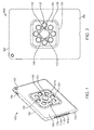
Figure 1 is an isometric rear view of a mountable case in accordance with an exemplary embodiment; -
Figure 2 is a rear view of a mountable case in accordance with an exemplary embodiment; -
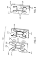
Figure 3 is an exploded view of a mounting plate in accordance with an exemplary embodiment; -
Figure 4 is an isometric view of an assembled mounting plate in accordance with an exemplary embodiment; -
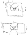
Figure 5 is an isometric view of a mountable case assembly in a portrait orientation in accordance with an exemplary embodiment; -
Figure 6 is an isometric view of a mountable case assembly in a landscape orientation in accordance with an exemplary embodiment; -
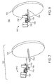
Figure 7 is an exploded view of a wall mount assembly in accordance with an exemplary embodiment; -
Figure 8 is an isometric view of an assembled wall mount assembly in accordance with an exemplary embodiment; -
Figure 9 is an exploded view of a mountable case assembly in accordance with a first exemplary embodiment; and -
Figure 10 is an exploded view of an alternate mountable case assembly in accordance with an exemplary embodiment. - Referring to
Figures 1 and 2 , a mountable case in accordance with an exemplary embodiment are illustrated. Themountable case 100 can receive and secure a portable electronic device. For example, the portable electronic device can be a tablet such as an iPad® or HP® Slate, a smartphone such as an iPhone® or Samsung® Galaxy™, a portable digital assistant (PDA), a laptop, e-book, or the like. Themountable case 100 is made from a strong, durable material configured to protect the portable electronic device from damage. Themountable case 100 includes ahousing 102. Thehousing 102 can be made of plastic, or alternatively a non-magnetic metal, such as aluminum. Thehousing 102 includes a front face 104 (shown inFigures 9 and10 ) and aback face 106, opposed to thefront face 104. Thefront face 104 can include a soft or plush lining (not shown) to assist in preventing scratching of the outer surface of a portable electronic device. Thehousing 102 includes a plurality ofretention portions 110 on the outside edge or side of thefront face 104. The plurality ofretention portions 110 can receive a portable electronic device and secure the portable electronic device to themountable case 100. The plurality ofretention portions 110 are sufficiently flexible to allow the portable electronic device to snap in and are sufficiently firm to retain the portable electronic device when engaged. - Alternatively, other retention means as known in the art can be used. As shown, the
plurality retention portions 110 extend the entire length of each edge or side of thehousing 102. Alternatively, the plurality ofretention portions 110 can extend only a portion of each edge or side, or the plurality ofretention portions 110 can be located intermittently on the edge or side of thehousing 102. - The portable electronic device can have exterior user interfaces that may need to be accessible when the portable electronic device is secure to the
mountable case 100. These interfaces can include, but are not limited to, a camera button(s), volume button(s), power port, microphone, speaker, headphone jack, and silence button. Theretention portions 110 can include one ormore apertures mountable case 100. The location of the one ormore apertures more apertures mountable case 100. - As shown, a coupling component includes a
mount protrusion 120 which extends outward from theback face 106 of thehousing 102. Themount protrusion 120 includes one ormore flanges 122. Eachflange 122 is formed on an outer peripheral edge of themount protrusion 120 and extends radially toward the periphery of thehousing 102. Eachflange 122 extends a distance from theprotrusion 120 thus forming a space beneath eachflange 122. Themount protrusion 120 includes fourflanges 122 which are offset from eachadjacent flange 122 by ninety degrees (90°). Alternatively, the number offlanges 122, the shape of eachflange 122 and the offset angle can vary. - As explained below, each
flange 122 can engage with a correspondingflange retention portion 310 on a mounting plate 300 (shown inFigures 3 and 4 ) to secure themountable case 100 to amounting plate 300 of a base assembly 500 (shown inFigures 5 and 6 ). For example, during engagement, theflanges 122 slide beneath a correspondingflange retention portion 310 thus preventing lifting of themounting plate 300 from the mountable case. Themount protrusion 120 extends through aprotrusion aperture 140 formed in amagnetic plate 130 and extends beyond the outer surface of themagnetic plate 130. - As shown, a coupling component includes a
magnetic plate 130 configured to engage with one or more corresponding magnetic elements 312 (shown inFigures 3 and 4 ) to secure themountable case 100 to a mountingplate 300 of a base assembly 500 (shown inFigures 5 and 6 ) magnetically. Themagnetic plate 130 can be secured to theback face 106 of thehousing 102. Theback face 106 can include aplate depression 124 configured to receive themagnetic plate 130. Themagnetic plate 130 can be secured to theback face 106 using one or more known securement means known in the art. For example, an adhesive can permanently couple themagnetic plate 130 with thehousing 102. Alternatively, one or more fasteners, such as screws, can secure themagnetic plate 130 to theback face 106. Alternatively, themagnetic plate 130 can be integrally formed within theplate depression 124 and/or in theback face 106. - The
magnetic plate 130 is a suitable magnetic material including, but not limited to, a ferromagnetic plate, plastic magnetic plate or ferrous metal plate, such as a steel plate, or any combination thereof. Themagnetic plate 130 can form a plurality ofplate apertures 132. Eachplate aperture 132 can receive a correspondingmagnetic element 312 of the mounting plate 300 (shown inFigures 3 and 4 ). As shown, the plurality ofplate apertures 132 together form a substantially circular shape and eachplate aperture 132 is offset forty-five degrees (45°) from anadjacent plate aperture 132. Alternatively, the plurality ofplate apertures 132 can vary in number, shape, arrangement and/or offset angles. - Referring to
Figures 3 and 4 , a mounting plate in accordance with an exemplary embodiment are illustrated. As shown inFigure 3 , the mountingplate 300 can include afirst plate 302 and asecond plate 304. As shown inFigure 4 , thefirst plate 302 andsecond plate 304 are assembled or coupled together to form the mountingplate 300. - The
first plate 302 can form a mountingplate aperture 306 configured to receive themount protrusion 120 of themountable case 100. The mountingplate aperture 306 can form alternatingflange receiving portions 308 andflange retention portions 310. Eachflange receiving portion 308 can be shaped to receive acorresponding flange 122. Eachflange retention portion 310 can be shaped to retain acorresponding flange 122 when themount protrusion 120 is received via theflange receiving portion 310 and the mountingcase 100 is rotated clockwise or counterclockwise. For example, themountable case 100 can be rotated less than ninety degrees (90°) in either the clockwise or counterclockwise direction, during which, theflanges 122 can slide beneath the correspondingflange retention portion 310, thus preventing removal. - To disengage the
flanges 122 from theflange retention portions 310, themountable case 100 can be rotated clockwise or counterclockwise to move theflanges 122 from beneath theflange retention portions 310 and align each of theflanges 122 with a correspondingflange receiving portion 308. - The
flange receiving portions 308 are essentially open apertures thereby permitting lifting of theflanges 122 therefrom. The number offlange receiving portions 308 andflange retaining portions 310 can correspond to the number offlanges 122. - The
first plate 302 includes a plurality of magnetic element covers 314. Eachmagnetic element cover 314 can receive amagnetic element 312 extending from thesecond plate 304. Eachmagnetic element cover 314 can extend from anoutermost surface 318 of the mountingplate 300. - The
second plate 304 can include a plurality of magneticelement receiving depressions 316 with each magneticelement receiving depression 316 configured to receive amagnetic element 312. As shown, there are four magneticelement receiving depressions 316. However the number of magneticelement receiving depressions 316 can vary. - Each
magnetic element 312 can be coupled with a corresponding magneticelement receiving depression 316 via a coupling means as known in the art. For example, the coupling means can be an adhesive, one or more retention pieces or using other suitable fastening means know in the art. Themagnetic elements 312 can be made of any suitable magnetic material, and can be for example, a magnet. Eachmagnetic element 312 extends beyond atop surface 320 of thesecond plate 304. The size, shape, strength and quantity ofmagnetic elements 312 can vary and depend on the required magnetic attraction to secure themountable case 100 with the mountingplate 300. A heavier portable electronic device can require additional magnetic attraction to secure themountable case 100 compared to a lighter portable electronic device. - The
first plate 302 can be coupled with thesecond plate 304 via a coupling means known in the art. For example, the coupling means can include welding, snap in components or any other suitable fastening means known in the art. Alternatively, themount plate 300 can be formed as a single piece with the plurality ofmagnetic elements 312 disposed within the mountingplate 300. - Referring to
Figures 5 and 6 , mountable case assemblies in accordance with exemplary embodiments are illustrated. As shown inFigures 5 and 6 , themountable case assemblies 500 can be in a portrait orientation and a landscape orientation, respectively. - The
mountable case assembly 500 can include themountable case 100 coupled to ahinge assembly 502 which is coupled to abase mount 502. When themountable case 100 is coupled to the mountingplate 300, each of the four magnetic element covers 314 are received and reside in one of the eightplate apertures 132. As themountable case 100 is rotated relative to the mountingplate 300, the magnetic element covers 314 can move from oneplate aperture 132 to the nextadjacent plate aperture 132. As a result, themountable case 100 can be positioned in eight different orientations relative to the mountingplate 300. In four alternating orientations, theflanges 122 and theflange retention portions 310 can be lockingly engaged, thereby preventing removal of themountable case 100 from the mountingplate 300. In four oppositely alternating orientations, theflanges 122 and theflange retention portions 310 are free of engagement, thereby allowing removal of themountable case 100 from the mountingplate 300. In an unlocked orientation, themountable case 100 and the mountingplate 300 can be coupled together by magnetic attraction, though they can be separated with an intervening force. - The magnetic element covers 314 and the
plate apertures 132 are located such that themountable case 100 can be coupled to the mountingplate 300 in a landscape orientation or in a portrait orientation. The number of locked and unlocked arrangements and their respective orientations depends on the number offlanges 122 and the number offlange retention portions 310. - The
mountable case assembly 500 can include thehinge assembly 502 and awall mount 504 which preferably is substantially planar. Thehinge assembly 502 can allow adjustment between varying viewing angles of the mountingcase 100 while secured with the mountingplate 300 of themountable case assembly 500. Thehinge assembly 502 can have a single axis of rotation allowing the mountingcase 100 to be tilted with respect to awall mount 504. Thewall mount 504 can secure themountable case assembly 500 to a substantially planar surface such as a wall, shelf, door or the like, as explained below. - Referring to
Figures 7 and 8 , wall mount assemblies in accordance with an exemplary embodiment are illustrated. Thewall mount assembly 700 includes thehinge assembly 502 and thewall mount 504. Thehinge assembly 502 includes one or morehinge mounting plates 702 for coupling thehinge assembly 502 with the mountingplate 300 using one or more coupling means known in the art. For example, an adhesive can permanently couple thehinge mounting plates 702 with the mountingplate 300. Alternatively, one or more fasteners, such as screws, snap in components or welding can secure thehinge mounting plates 702 with the mountingplate 300. - The
hinge assembly 502 is detachably coupled with anextender 704 of awall mount 504. As shown, thehinge assembly 502 includes afirst extender plate 706 which can interact with asecond extender plate 708 to couple thehinge assembly 502 to theextender 704 via a press fit. More specifically, theextender 704 can reside between thefirst extender plate 706 and thesecond extender plate 708. A lockingarm 710 can move thesecond extender plate 708 between an unlocked position and a locked position. Alternatively, other known coupling means can couple thehinge assembly 502 with theextender 704 as known in the art. - The
extender 704 extends from awall mount 504. Theextender 704 is integrally formed with thewall mount 504. Alternatively, theextender 704 can be coupled to thewall mount 504 using coupling means known in the art. For example, theextender 704 can pass through a slot in thewall mount 504, or can secure theextender 704 with thewall mount 504 using one or more fasteners such as screws, adhesive or any suitable securement means known in the art. - The
wall mount 504 can be secured to a planar surface, such as a wall, using one or more securing means as known in the art. For example, thewall mount 504 can be secured to a planar surface using fasteners such as screws, adhesive or any suitable securing means that secures thewall mount 504 with a substantially planar surface. - Referring to
Figure 9 , an exploded view of a mountable case assembly in accordance with an exemplary embodiment is illustrated. As shown, themountable case assembly 900 includes amountable case 100 having amagnetic plate 130 detachably coupled to a mountingplate 300 which in turn can be detachably coupled to anextender 704 of awall mount 504 via ahinge assembly 502. Thehinge assembly 502 can be detachably coupled to theextender 704. The mountingplate 300 can include afirst plate 302 and asecond plate 304 with one or moremagnetic elements 312 interposed between the twoplates mountable case 100 can be coupled to the mountingplate 300 via magnetically and/or physically via amount protrusion 120 and correspondingflange retention portions 310. - Referring to
Figure 10 , an exploded view of a mountable case assembly in accordance with an alternate exemplary embodiment is illustrated. As shown, themountable case assembly 800 includes amountable case 100 having amagnetic plate 130 detachably coupled to a mountingplate 300 which in turn can be detachably coupled to anextender 704 of awall mount 504 via ahinge assembly 502. Thehinge assembly 502 can be detachably coupled to theextender 704. In this embodiment, the coupling components are reversed compared to the coupling components inFigure 9 . As shown, themagnetic plate 130 can include the alternatingflange receiving portions 308 andflange retention portions 310 and the mountingplate 300 can include themount protrusion 120. As shown, themagnetic plate 130 can include the plurality ofmagnetic elements 312 extending outwardly and the mountingplate 300 can form the plurality ofplate apertures 132. In this embodiment, themagnetic plate 130 is made of a non-magnetic material and includes themagnetic elements 312 with the mountingplate 300 being magnetic. Alternatively, themagnetic plate 130 can include one or more magnetic element covers 314 extending outwardly and can form one ormore plate apertures 132 and the mountingplate 300 can include one or more magnetic element covers 314 extending outwardly and can form one ormore plate apertures 132. - In one or more embodiments, the magnetic element covers 314 are not used and the
magnetic elements 312 can engage with theplate apertures 132. - The embodiments shown and described above are only examples. Therefore, many details are neither shown nor described. Even though numerous characteristics and advantages of the present technology have been set forth in the foregoing description, together with details of the structure and function of the present disclosure, the disclosure is illustrative only, and changes may be made in the detail, especially in matters of shape, size and arrangement of the parts within the principles of the present disclosure to the full extent indicated by the broad general meaning of the terms used in the attached claims. It will therefore be appreciated that the embodiments described above may be modified within the scope of the appended claims.
Claims (15)
- A mountable case assembly (500, 800, 900) for protecting a portable electronic device, comprising:a mountable case (100) having a front face (104) and a back face (106) with the front face (104) and the back face (106) being opposed to one another, the mountable case (100) configured to receive the portable electronic device;a mounting plate (300); andat least one coupling component configured to couple the mountable case (100) with the mounting plate (300), the at least one coupling component including at least one of:a physical coupling component comprising:a mount protrusion (120) including one or more flanges (122) extending radially from the mount protrusion (120); andalternating flange receiving portions (308) and flange retention portions (310), with the flange receiving portions (308) configured to receive the one or more flanges (122) and the flange retention portions (310) configured to secure the one or more flanges (122) when the mountable case (100) is rotated;wherein the mount protrusion (120) extends outwardly from one of the back face (106) of the mountable case (100) or a front surface of the mounting plate (300) and the flange receiving portions (308) and flange retention portions (310) are formed in one of a magnetic plate (130) coupled to the back face (106) of the mountable case (100) or formed in the mounting plate (300), whichever does not contain the mount protrusion (120);a magnetic coupling component comprising:a plurality of plate apertures (132);a plurality of magnetic elements (312) extending outwardly;wherein the plurality of plate apertures (132) are formed in one of the magnetic plate (130) or formed in the mounting plate (300) and the plurality of magnetic elements (312) are coupled to one of the magnetic plate (130) or the mounting plate (300), whichever does not contain the plurality of plate apertures (132), with each plate aperture (132) configured to receive a corresponding magnetic element (312).
- The mountable case assembly (500, 800, 900) of claim 1 wherein there are four flanges (122), four flange receiving portions (308) and four flange retention portions (310).
- The mountable case assembly (500, 800, 900) of claim 2 wherein each of the flanges (122) is offset ninety degrees from an adjacent flange (122).
- The mountable case assembly (500, 800, 900) of any of claims 1 - 3 wherein there are four magnetic elements (312) and eight plate apertures (132).
- The mountable case assembly (500, 800, 900) of claim 4 wherein the eight plate apertures (132) form a substantially circular shape and each plate aperture (132) is offset forty-five degrees from an adjacent plate aperture (132).
- The mountable case assembly (500, 800, 900) of claim 4 or 5 wherein four of the plate apertures (132) are formed at locations with each of the four plate apertures (132) configured receive one of the magnetic elements (312) when the mountable case (100) is coupled with the mounting plate (300) whereby the mountable case (100) is in a landscape orientation with respect to the mounting plate (300).
- The mountable case assembly (500, 800, 900) of claim 6 wherein the other four plate apertures (132) are formed at locations with each of the other four plate apertures (132) configured to receive one of the magnetic elements (312) when the mountable case (100) is coupled with the mounting plate (300) whereby the mountable case (100) is in a portrait orientation with respect to the mounting plate (300).
- The mountable case assembly (500, 800, 900) of any of claims 1 - 7 wherein
the mount protrusion (120) extends outwardly from the back face (106) of the mountable case (100);
the mountable case assembly (500, 800, 900) comprises a magnetic plate (130) coupled to the back face (106) of the mountable case (100), the magnetic plate (130) forming a protrusion aperture (140) from which the mount protrusion (120) extends through; and
the alternating flange receiving portions (308) and flange retention portions (310) are formed in the mounting plate (300). - The mountable case assembly (500, 800, 900) of any of claims 1 - 8 wherein
the mounting plate (300) comprising a plurality of magnetic elements (312) extending from a front surface of the mounting plate (300); and
the mountable case assembly (500, 800, 900) comprises a magnetic plate (130) coupled to the back face (106) of the mountable case (100), the plurality of plate apertures (132) are formed in the mounting plate (300) with each plate aperture (132) configured to receive one of the plurality of magnetic elements (312). - The mountable case assembly (500, 800, 900) of any of claims 1 - 9 wherein the magnetic plate (300) is a ferromagnetic plate.
- The mountable case assembly (500, 800, 900) of any of claims 1 - 10 wherein the mounting plate (300) comprises:a first plate (302) comprising four magnetic element covers (314) extending from an outermost surface of the first plate (302) and configured to receive a magnetic element (312);a second plate (304) comprising four magnetic element receiving depressions (316);four magnetic elements (312), each residing in one of the four magnetic element receiving depressions (316) and extending into one of the four magnetic covers (314);wherein each of the plurality of plate apertures (132) is configured to receive one of the four magnetic element covers (314).
- The mountable case assembly (500, 800, 900) of any of claims 1 - 11 further comprising a wall mount (504) coupled to the mounting plate (300) and configured to be coupled to a flat surface.
- The mountable case assembly (500, 800, 900) of any of claims 1 - 12 further comprising a hinge assembly (502) coupled to the mounting plate (300).
- The mountable case assembly (500, 800, 900) of claim 12 or 13 wherein the wall mount (504) further comprises an extender (704) extending from the wall mount (504) and the hinge assembly (502) is detachably coupled to the extender (704).
- The mountable case assembly (500, 800, 900) of claim 13 or 14 wherein the hinge assembly (502) is configured to tilt the mountable case (100) with respect to the wall mount (504).
Applications Claiming Priority (3)
| Application Number | Priority Date | Filing Date | Title |
|---|---|---|---|
| US201462086591P | 2014-12-02 | 2014-12-02 | |
| US201562101114P | 2015-01-08 | 2015-01-08 | |
| US14/639,799 US20160150861A1 (en) | 2014-12-02 | 2015-03-05 | Mountable case assembly |
Publications (1)
| Publication Number | Publication Date |
|---|---|
| EP3029543A1 true EP3029543A1 (en) | 2016-06-08 |
Family
ID=55066283
Family Applications (1)
| Application Number | Title | Priority Date | Filing Date |
|---|---|---|---|
| EP15197590.1A Withdrawn EP3029543A1 (en) | 2014-12-02 | 2015-12-02 | Mountable case assembly |
Country Status (4)
| Country | Link |
|---|---|
| US (1) | US20160150861A1 (en) |
| EP (1) | EP3029543A1 (en) |
| CN (1) | CN105652968A (en) |
| TW (1) | TWI563902B (en) |
Cited By (7)
| Publication number | Priority date | Publication date | Assignee | Title |
|---|---|---|---|---|
| EP3343047A1 (en) * | 2016-12-27 | 2018-07-04 | Lg Electronics Inc. | Display device |
| KR20180076200A (en) * | 2016-12-27 | 2018-07-05 | 엘지전자 주식회사 | Display device |
| WO2018140721A1 (en) * | 2017-01-26 | 2018-08-02 | Bose Corporation | Electronics enclosure mounting |
| EP3636979A1 (en) * | 2018-10-12 | 2020-04-15 | Investment Group "Kopernik", LLC | Stand holder for a mobile device |
| US10795185B1 (en) | 2019-06-13 | 2020-10-06 | NextVPU (Shanghai) Co., Ltd. | Connector, assistive device and wearable device |
| US10989933B2 (en) | 2019-04-18 | 2021-04-27 | NextVPU (Shanghai) Co., Ltd. | Connector, assistive device and wearable device |
| WO2021144530A1 (en) * | 2020-01-17 | 2021-07-22 | Axess Vision Technology | System for joining a device, in particular a medical device, to a support |
Families Citing this family (54)
| Publication number | Priority date | Publication date | Assignee | Title |
|---|---|---|---|---|
| US9295174B2 (en) | 2014-01-07 | 2016-03-22 | Otter Products, Llc | Protective enclosure for an electronic device |
| US9847805B2 (en) * | 2014-08-19 | 2017-12-19 | World Richman Manufacturing Corporation | Cradle-case combination with magnetic fastener feature |
| CN107005712B (en) * | 2014-10-21 | 2020-01-03 | Lg 电子株式会社 | Method and apparatus for performing graph-based prediction using optimization function |
| US9836101B1 (en) | 2014-11-11 | 2017-12-05 | Darren Saravis | Cooling mount |
| US11262816B2 (en) * | 2014-11-11 | 2022-03-01 | Darren Saravis | Temperature regulating mount with magnetic power mount |
| US11836020B2 (en) | 2014-11-11 | 2023-12-05 | Darren Saravis | Temperature regulating mount |
| US12235695B2 (en) | 2014-11-11 | 2025-02-25 | Darren Saravis | Temperature regulating mount with magnetic power mount |
| US9986805B2 (en) | 2015-03-30 | 2018-06-05 | Otter Products, Llc | Protective enclosure for an electronic device |
| US9681718B1 (en) * | 2015-05-07 | 2017-06-20 | Timothy E. Poole | Combined device mount and protective case |
| US10058155B2 (en) | 2015-07-19 | 2018-08-28 | Otter Products, Llc | Protective case system |
| USD776747S1 (en) * | 2015-11-30 | 2017-01-17 | 3 Legged Thing Limited | Mount for cameras and cinematographic apparatus |
| US10237384B2 (en) | 2016-03-09 | 2019-03-19 | Josh Holder | Hands-free mount for mobile devices |
| US10342366B2 (en) * | 2016-06-09 | 2019-07-09 | MaxwellHook LLC | Adjustable magnetic surface mount |
| US10703297B1 (en) * | 2016-08-26 | 2020-07-07 | Apple Inc. | System for holding devices in a passenger vehicle |
| DE102016116580B4 (en) * | 2016-09-05 | 2019-08-29 | Bury Sp.Z.O.O | Holder system for an electronic device |
| US9913388B1 (en) * | 2016-09-29 | 2018-03-06 | Hamid Mchatet | Universal magnetic mounting assembly |
| US9935669B1 (en) * | 2017-03-10 | 2018-04-03 | Kuo-Tang Kuo | Protection enclosure of portable electronic device |
| WO2019028502A1 (en) * | 2017-08-07 | 2019-02-14 | Arb Corporation Ltd | Assembly for mounting an accessory to a vehicle |
| AU201714647S (en) * | 2017-08-07 | 2017-09-22 | Arb Corp Ltd | A mount for a portable device |
| US11178986B2 (en) * | 2017-11-28 | 2021-11-23 | Darren Mark Maynard | Positioning and stabilizing device for picture frames and the like |
| US10623043B2 (en) | 2018-01-23 | 2020-04-14 | Otter Products, Llc | Protective case for electronic device |
| US10441096B2 (en) * | 2018-03-06 | 2019-10-15 | Chul Chung | Mounting device for attaching a display device, a picture frame, or the like to a supporting structure |
| US10750844B2 (en) | 2018-03-15 | 2020-08-25 | Otter Products, Llc | Protective case for use with device grip |
| US10694835B2 (en) | 2018-03-15 | 2020-06-30 | Otter Products, Llc | Protective case for use with device grip |
| TWI677167B (en) * | 2018-08-08 | 2019-11-11 | 愛進化科技股份有限公司 | Protective case |
| TWI732412B (en) * | 2019-01-07 | 2021-07-01 | 鴻海精密工業股份有限公司 | Electronic apparatus and base mount kit thereof |
| GB201903761D0 (en) * | 2019-03-19 | 2019-05-01 | Fleury Michel | Cellular phone casing and casing accessory having a means for holding by way of a complaint mechanism |
| US11320724B2 (en) * | 2019-05-13 | 2022-05-03 | Peak Design | Close-pack, high-aspect-ratio camera tripod |
| USD897329S1 (en) | 2019-07-02 | 2020-09-29 | Otter Products, Llc | Case for a smartphone |
| US11548451B2 (en) | 2019-07-31 | 2023-01-10 | Peak Design | Mobile device mounting system |
| CN114980602B (en) * | 2019-07-31 | 2024-06-14 | 尖峰设计公司 | Mobile device installation system |
| USD898728S1 (en) * | 2020-01-15 | 2020-10-13 | Huafa Lin | Case for smartphone |
| US11552667B2 (en) | 2020-09-22 | 2023-01-10 | Brian Robert Balderston | Adaptive support accessory for mobile devices |
| US12465846B2 (en) * | 2020-09-25 | 2025-11-11 | Apple Inc. | Magnetically attachable gaming accessory |
| WO2022066134A1 (en) * | 2020-09-28 | 2022-03-31 | Сергей Дмитриевич ПОЛИНКЕВИЧ | Electronic device holder |
| US11920727B2 (en) * | 2021-01-16 | 2024-03-05 | Videndum Media Solutions Spa | Deployable light for electronic devices |
| US11265035B1 (en) * | 2021-02-08 | 2022-03-01 | Ping Zhang | Mobile device holder |
| US12075929B2 (en) * | 2021-03-03 | 2024-09-03 | Abbyrose, Llc | Phone case wall display and organizer |
| US11564508B2 (en) * | 2021-03-03 | 2023-01-31 | Abbyrose, Llc | Phone case wall display and organizer |
| US12433391B2 (en) | 2021-03-29 | 2025-10-07 | Otter Products, Llc | Collapsible and extendable device grip |
| EP4342164A4 (en) | 2021-05-28 | 2025-04-09 | Peak Design | MOBILE TRIPOD MOUNTING SYSTEM |
| US12531435B2 (en) | 2021-12-17 | 2026-01-20 | Annex Products Pty. Ltd. | Wireless charger mounting system |
| US11622035B1 (en) * | 2022-01-14 | 2023-04-04 | Guangdong Xizhiongxi Technology Co., Ltd. | Waterproof phone case |
| USD1024048S1 (en) | 2022-06-28 | 2024-04-23 | Annex Products Pty Ltd | Mounting head |
| USD1087942S1 (en) | 2022-06-28 | 2025-08-12 | Annex Products Pty. Ltd. | Case for mobile electronic device |
| USD1024049S1 (en) | 2022-06-28 | 2024-04-23 | Annex Products Pty Ltd | Mounting head |
| USD1028964S1 (en) | 2022-06-29 | 2024-05-28 | Annex Products Pty Ltd | Desk stand |
| IT202200003987U1 (en) * | 2022-10-04 | 2024-04-04 | Ferraris Group S A G L | Support device for a portable processing and/or telecommunication apparatus or an accessory |
| US12294404B1 (en) * | 2022-10-18 | 2025-05-06 | Arrotech Group Llc | Protective case for portable electronic devices |
| US12575654B2 (en) | 2022-11-09 | 2026-03-17 | Otter Products, Llc | Protective case with grip and stand |
| US20240219970A1 (en) * | 2023-01-04 | 2024-07-04 | ohSnap, Inc. | Configurations for Grips for Portable Handheld Devices |
| USD1071839S1 (en) | 2023-03-10 | 2025-04-22 | Annex Products Pty. Ltd. | Battery attachment |
| USD1076425S1 (en) | 2023-03-16 | 2025-05-27 | Annex Products Pty. Ltd. | Wallet attachment |
| USD1084650S1 (en) * | 2024-05-31 | 2025-07-22 | Shenzhen Huiwei Trading Co., Ltd. | Magnetic suction phone holder |
Citations (3)
| Publication number | Priority date | Publication date | Assignee | Title |
|---|---|---|---|---|
| US20130181584A1 (en) * | 2012-01-12 | 2013-07-18 | Rokform Llc | Case and mount system for handheld electronic device |
| EP2751640A1 (en) * | 2011-09-27 | 2014-07-09 | Jason A. Sullivan | Systems and methods for mounting dynamically modular processing units |
| US20140262847A1 (en) * | 2013-03-15 | 2014-09-18 | The Joy Factory, Inc. | Case structures for portable electronic devices |
Family Cites Families (40)
| Publication number | Priority date | Publication date | Assignee | Title |
|---|---|---|---|---|
| WO2004083658A1 (en) * | 2003-03-17 | 2004-09-30 | Koninklijke Philips Electronics N.V. | Flat panel display unit provided with attachment means and attachment unit for the removable attachment of an object |
| ES2619517T3 (en) * | 2008-04-15 | 2017-06-26 | Vista Outdoor Operations Llc | Adjustable and detachable system for attachment attachment |
| TWM343192U (en) * | 2008-05-20 | 2008-10-21 | Cheng-Yu Huang | Heat dissipation pad of simple-type notebook |
| US20120301067A1 (en) * | 2008-08-26 | 2012-11-29 | Morgan Christopher J | Apparatus and methods for forming kinematic coupling components |
| US8960634B2 (en) * | 2008-09-09 | 2015-02-24 | Zero Chroma, LLC | Holder for electronic device with support |
| US9316344B2 (en) * | 2013-01-07 | 2016-04-19 | Zero Chroma, LLC | Systems, methods, and apparatuses for supporting electronic devices |
| US8382059B2 (en) * | 2008-09-09 | 2013-02-26 | Zero Chroma, LLC | Holder for electronic device with support |
| US20100327030A1 (en) * | 2009-06-30 | 2010-12-30 | Shang-Wen Yang | portable binder with a rotating frame |
| WO2011139823A2 (en) * | 2010-04-28 | 2011-11-10 | Belkin International, Inc. | Case configured to removably couple to a portable electrical device and method of providing and use thereof |
| US20120111881A1 (en) * | 2010-06-07 | 2012-05-10 | 360 Mobility Solutions, Llc | Protective cases for electronic devices |
| US20120113572A1 (en) * | 2010-06-07 | 2012-05-10 | 360 Mobility Solutions, Llc | Method and system for electronic device cases |
| US8740270B1 (en) * | 2010-06-09 | 2014-06-03 | John Mizell | Portable electronic device holder |
| US8690210B1 (en) * | 2010-06-17 | 2014-04-08 | Brian May | Computer case shell with handgrip |
| WO2012012588A1 (en) * | 2010-07-20 | 2012-01-26 | Dc Mobile Design, Llc | Personal electronic device holder systems |
| US9074725B2 (en) * | 2010-07-29 | 2015-07-07 | Kevin Trotsky | Mobile electronic device positioning unit |
| US9581291B2 (en) * | 2010-07-29 | 2017-02-28 | Octa Llc | Positioning grip for a mobile electronic device |
| US8941989B2 (en) * | 2010-09-29 | 2015-01-27 | James W. Pollex | Tablet computer holder and stand |
| US20120118770A1 (en) * | 2010-11-15 | 2012-05-17 | Valls William H | Tablet accessory |
| US20120175474A1 (en) * | 2011-01-06 | 2012-07-12 | Brandon Barnard | Electronic device holder |
| CN102096451A (en) * | 2011-01-29 | 2011-06-15 | 昆山易昌泰电子有限公司 | Connection structure for tablet computer and bracket thereof |
| US8706175B2 (en) * | 2011-03-30 | 2014-04-22 | Richard H Cho | Phone and tablet stand |
| MX345636B (en) * | 2011-12-22 | 2017-02-08 | Treefrog Dev Inc | ACCESSORIES FOR USE WITH ACCOMMODATION FOR AN ELECTRONIC DEVICE. |
| US8567744B1 (en) * | 2012-01-03 | 2013-10-29 | The United States Of America, As Represented By The Secretary Of The Navy | Reusable breakaway mounting device |
| US9185953B2 (en) * | 2012-01-12 | 2015-11-17 | Rokform Llc | Case and mount system for handheld electronic device |
| US8870143B2 (en) * | 2012-02-21 | 2014-10-28 | Dmitry Kubin | Low profile secure asymmetrical turn-lock coupling mechanism with magnetic rotational orientation locks |
| EP2689875A1 (en) * | 2012-07-27 | 2014-01-29 | Zfx GmbH | Coupling device |
| US8939482B2 (en) * | 2012-09-19 | 2015-01-27 | Kara M. Rasmussen | Support system for digital tablet devices |
| KR101436954B1 (en) * | 2012-11-23 | 2014-09-04 | (주)에이스 힌지텍 | Terminal stand |
| CN203057252U (en) * | 2012-12-06 | 2013-07-10 | 易东 | Vehicle magnetic cell phone mount |
| US9448588B2 (en) * | 2012-12-12 | 2016-09-20 | Brandon Barnard | Electronic device holder |
| US20140191096A1 (en) * | 2013-01-04 | 2014-07-10 | Garmin Switzerland Gmbh | Magnetic device mount |
| US9689527B2 (en) * | 2013-03-15 | 2017-06-27 | Lee Christopher Franklin | Mounting apparatus |
| US9611881B2 (en) * | 2013-03-15 | 2017-04-04 | Otter Products, Llc | Releasable mount apparatus and system |
| US9678537B2 (en) * | 2013-04-30 | 2017-06-13 | Victor Kupferstein | Mobile device case and peripheral system |
| US9335789B2 (en) * | 2013-05-10 | 2016-05-10 | Adam Merzon | System and apparatus for mounting a handheld electronic device |
| US9375073B2 (en) * | 2013-05-28 | 2016-06-28 | John Traylor Orr, Jr. | Tablet support accessory |
| US9019698B2 (en) * | 2013-05-30 | 2015-04-28 | Jean-Michel Thiers | Mounting system for electronic device |
| US9615650B2 (en) * | 2013-12-02 | 2017-04-11 | Superior Communications, Inc. | Armband for an electronic device |
| US9821724B2 (en) * | 2015-02-10 | 2017-11-21 | Ping Zhang | Mounting apparatus for portable electronic device |
| US9397719B1 (en) * | 2015-06-17 | 2016-07-19 | Airo Collective, Inc. | Mobile device holder |
-
2015
- 2015-03-05 US US14/639,799 patent/US20160150861A1/en not_active Abandoned
- 2015-07-21 TW TW104123490A patent/TWI563902B/en not_active IP Right Cessation
- 2015-12-02 EP EP15197590.1A patent/EP3029543A1/en not_active Withdrawn
- 2015-12-02 CN CN201510869733.3A patent/CN105652968A/en not_active Withdrawn
Patent Citations (3)
| Publication number | Priority date | Publication date | Assignee | Title |
|---|---|---|---|---|
| EP2751640A1 (en) * | 2011-09-27 | 2014-07-09 | Jason A. Sullivan | Systems and methods for mounting dynamically modular processing units |
| US20130181584A1 (en) * | 2012-01-12 | 2013-07-18 | Rokform Llc | Case and mount system for handheld electronic device |
| US20140262847A1 (en) * | 2013-03-15 | 2014-09-18 | The Joy Factory, Inc. | Case structures for portable electronic devices |
Cited By (11)
| Publication number | Priority date | Publication date | Assignee | Title |
|---|---|---|---|---|
| EP3343047A1 (en) * | 2016-12-27 | 2018-07-04 | Lg Electronics Inc. | Display device |
| KR20180076200A (en) * | 2016-12-27 | 2018-07-05 | 엘지전자 주식회사 | Display device |
| US10390451B2 (en) | 2016-12-27 | 2019-08-20 | Lg Electronics Inc. | Display device |
| WO2018140721A1 (en) * | 2017-01-26 | 2018-08-02 | Bose Corporation | Electronics enclosure mounting |
| US10492602B2 (en) | 2017-01-26 | 2019-12-03 | Bose Corporation | Electronics enclosure mounting |
| EP3636979A1 (en) * | 2018-10-12 | 2020-04-15 | Investment Group "Kopernik", LLC | Stand holder for a mobile device |
| US10989933B2 (en) | 2019-04-18 | 2021-04-27 | NextVPU (Shanghai) Co., Ltd. | Connector, assistive device and wearable device |
| US10795185B1 (en) | 2019-06-13 | 2020-10-06 | NextVPU (Shanghai) Co., Ltd. | Connector, assistive device and wearable device |
| WO2021144530A1 (en) * | 2020-01-17 | 2021-07-22 | Axess Vision Technology | System for joining a device, in particular a medical device, to a support |
| FR3106265A1 (en) * | 2020-01-17 | 2021-07-23 | Axess Vision Technology | System for assembling a device, in particular a medical device, with a support |
| US12313210B2 (en) | 2020-01-17 | 2025-05-27 | Axess Vision Technology | System for joining a device, in particular a medical device, to a support |
Also Published As
| Publication number | Publication date |
|---|---|
| US20160150861A1 (en) | 2016-06-02 |
| TWI563902B (en) | 2016-12-21 |
| TW201622536A (en) | 2016-06-16 |
| CN105652968A (en) | 2016-06-08 |
Similar Documents
| Publication | Publication Date | Title |
|---|---|---|
| US20160150861A1 (en) | Mountable case assembly | |
| US8870143B2 (en) | Low profile secure asymmetrical turn-lock coupling mechanism with magnetic rotational orientation locks | |
| US11134580B2 (en) | Protective cover for portable electronic device and associated systems and methods | |
| EP2431984B1 (en) | Accessory device with magnetic attachment | |
| US9456674B2 (en) | Case supporting electronic device | |
| US9051764B1 (en) | Internal rotational locking mechanism | |
| US7594630B2 (en) | Mounting fixture for a peripheral device | |
| WO2013158058A1 (en) | Rotating mechanism for computer or similar device | |
| US20180184773A1 (en) | Case and mount for handheld electronic device | |
| US10848844B2 (en) | Device for installation and removal of a ceiling speaker system | |
| US20140305985A1 (en) | Apparatus for improving the interchangeability of portable electronic devices amongst various supports and related methods | |
| US20140198439A1 (en) | Cover for audio and video inputs | |
| WO2012036713A1 (en) | Magnetic attachment | |
| WO2012036716A1 (en) | Magnetic attachment system | |
| WO2012036717A1 (en) | Device with foldable cover and user interface for the device | |
| WO2012036712A1 (en) | Foldable accessory device | |
| WO2012036714A1 (en) | Device with foldable cover and user interface for the device | |
| WO2012036715A1 (en) | Device with foldable cover and user interface for the device | |
| WO2012036710A1 (en) | Device with foldable cover and user interface for the device | |
| US20160102809A1 (en) | Curved surface hook | |
| US9939104B2 (en) | Magnetic mount | |
| CN220582037U (en) | Support device for portable treatment and/or telecommunication equipment or accessories | |
| US20240148120A1 (en) | Protective case with grip and stand | |
| US9310837B2 (en) | Rotating mechanism for computer or similar device | |
| US20240333002A1 (en) | Mobile device mounting apparatus |
Legal Events
| Date | Code | Title | Description |
|---|---|---|---|
| PUAI | Public reference made under article 153(3) epc to a published international application that has entered the european phase |
Free format text: ORIGINAL CODE: 0009012 |
|
| AK | Designated contracting states |
Kind code of ref document: A1 Designated state(s): AL AT BE BG CH CY CZ DE DK EE ES FI FR GB GR HR HU IE IS IT LI LT LU LV MC MK MT NL NO PL PT RO RS SE SI SK SM TR |
|
| AX | Request for extension of the european patent |
Extension state: BA ME |
|
| 17P | Request for examination filed |
Effective date: 20161208 |
|
| RAV | Requested validation state of the european patent: fee paid |
Extension state: MD Effective date: 20161208 Extension state: MA Effective date: 20161208 |
|
| RAX | Requested extension states of the european patent have changed |
Extension state: ME Payment date: 20161208 Extension state: BA Payment date: 20161208 |
|
| RBV | Designated contracting states (corrected) |
Designated state(s): AL AT BE BG CH CY CZ DE DK EE ES FI FR GB GR HR HU IE IS IT LI LT LU LV MC MK MT NL NO PL PT RO RS SE SI SK SM TR |
|
| STAA | Information on the status of an ep patent application or granted ep patent |
Free format text: STATUS: THE APPLICATION IS DEEMED TO BE WITHDRAWN |
|
| 18D | Application deemed to be withdrawn |
Effective date: 20180703 |