EP3029446A1 - A gas-selective membrane and method of its production - Google Patents
A gas-selective membrane and method of its production Download PDFInfo
- Publication number
- EP3029446A1 EP3029446A1 EP16152458.2A EP16152458A EP3029446A1 EP 3029446 A1 EP3029446 A1 EP 3029446A1 EP 16152458 A EP16152458 A EP 16152458A EP 3029446 A1 EP3029446 A1 EP 3029446A1
- Authority
- EP
- European Patent Office
- Prior art keywords
- plate
- membrane
- gas
- layer
- windows
- Prior art date
- Legal status (The legal status is an assumption and is not a legal conclusion. Google has not performed a legal analysis and makes no representation as to the accuracy of the status listed.)
- Granted
Links
Images

Classifications
-
- B—PERFORMING OPERATIONS; TRANSPORTING
- B01—PHYSICAL OR CHEMICAL PROCESSES OR APPARATUS IN GENERAL
- B01D—SEPARATION
- B01D69/00—Semi-permeable membranes for separation processes or apparatus characterised by their form, structure or properties; Manufacturing processes specially adapted therefor
- B01D69/02—Semi-permeable membranes for separation processes or apparatus characterised by their form, structure or properties; Manufacturing processes specially adapted therefor characterised by their properties
-
- G—PHYSICS
- G01—MEASURING; TESTING
- G01M—TESTING STATIC OR DYNAMIC BALANCE OF MACHINES OR STRUCTURES; TESTING OF STRUCTURES OR APPARATUS, NOT OTHERWISE PROVIDED FOR
- G01M3/00—Investigating fluid-tightness of structures
- G01M3/02—Investigating fluid-tightness of structures by using fluid or vacuum
- G01M3/04—Investigating fluid-tightness of structures by using fluid or vacuum by detecting the presence of fluid at the leakage point
- G01M3/20—Investigating fluid-tightness of structures by using fluid or vacuum by detecting the presence of fluid at the leakage point using special tracer materials, e.g. dye, fluorescent material, radioactive material
- G01M3/202—Investigating fluid-tightness of structures by using fluid or vacuum by detecting the presence of fluid at the leakage point using special tracer materials, e.g. dye, fluorescent material, radioactive material using mass spectrometer detection systems
- G01M3/205—Accessories or associated equipment; Pump constructions
-
- B—PERFORMING OPERATIONS; TRANSPORTING
- B01—PHYSICAL OR CHEMICAL PROCESSES OR APPARATUS IN GENERAL
- B01D—SEPARATION
- B01D53/00—Separation of gases or vapours; Recovering vapours of volatile solvents from gases; Chemical or biological purification of waste gases, e.g. engine exhaust gases, smoke, fumes, flue gases, aerosols
- B01D53/34—Chemical or biological purification of waste gases
-
- B—PERFORMING OPERATIONS; TRANSPORTING
- B01—PHYSICAL OR CHEMICAL PROCESSES OR APPARATUS IN GENERAL
- B01D—SEPARATION
- B01D69/00—Semi-permeable membranes for separation processes or apparatus characterised by their form, structure or properties; Manufacturing processes specially adapted therefor
- B01D69/10—Supported membranes; Membrane supports
-
- B—PERFORMING OPERATIONS; TRANSPORTING
- B01—PHYSICAL OR CHEMICAL PROCESSES OR APPARATUS IN GENERAL
- B01D—SEPARATION
- B01D2325/00—Details relating to properties of membranes
- B01D2325/20—Specific permeability or cut-off range
Definitions
- the invention refers to a method for the production of a membrane comprising selectively gas-permeable windows.
- Selectively gas-permeable membranes are needed in measuring and analysis apparatuses in order to separate certain gases from other gases and to determine the presence of the interesting gases.
- a typical field of application of such membranes are leak detectors which detect a tracer gas flowing from a leak.
- Typical tracer gases are, among others, helium and hydrogen, which are light gases and pass through membranes that cannot be passed by heavier gases.
- the windows have been made by structured etching of the silicon disc from the rear and they are covered by a thin membrane.
- Each of the windows is provided with a helical heating element for local heating of the gas passage.
- This structure of a gas-selective membrane is complex.
- the membrane body is formed by a double plate made from two single silicon plates, with the gas-selectively permeable thin separating wall being located in the central region of the thickness of the membrane body.
- the first plate can be manufactured separately, with the layer having the selectivity properties being formed thereon, and may then be covered by the second plate and bonded therewith.
- the double plate gives the membrane body a great stability.
- the bottom wall of the second plate, which forms the gas-selective separating wall is protected against outside influences.
- the windows may have inclined or conically tapered flank walls made by anisotropic etching.
- the membrane can be manufactured using the same manufacturing techniques as described in EP 0 831 964 B1 , such as deposition, oxidizing and other methods known from semiconductor technology.
- the double plate provides the plate body with great stability overall, so that it is better adapted to withstand the different gas pressures usually prevailing on either side of the membrane.
- the first plate may be formed with recesses or passages. With recesses, a bottom wall is left. Preferably, the same is porosified so that it is pervious to gas and will thereafter serve as a supporting wall for supporting the gas-selective layer. With passages, these are narrower than the recesses in the first (lower) plate in order to reduce the size of the non-supported membrane surfaces.
- the invention further refers to a gas-selective membrane according to claim 1.
- the heating device is a radiant heating element that heats all windows together, the silicon disc serving as a radiation absorber.
- the radiant heating element may be an electrically heatable body and the membrane body may include a heat reflector layer in order to uniformly heat the membrane from both sides.
- a first plate 10 is illustrated under a), which plate is made of silicon and has a thickness of about 300 ⁇ m.
- This first plate is patterned on one side for instance by photochemical etching using KOH as the etchant, whereby the recesses 11 are formed. With anisotropic KOH etching, he recesses have inclined flanks 12 and a planar bottom wall 13 which is parallel to the plane of the plate. In a further step, the thin bottom walls are porosified such that they are pervious to gas.
- Figure 1 shows that the bottom walls 13 are porosified, whereby they are pervious to gas.
- Figure 1d illustrates the second plate 20 which is also made of silicon and has a thickness of about 300 ⁇ m.
- the second plate is planar and bears the selectively gas-permeable layer 21 on its bottom face, the layer being a thin SiO 2 layer of about 12 nm in thickness.
- the layer 21 has grown thermally or has been formed by CVD/ALD deposition.
- the second plate 20 is placed over the first plate 10 and is bonded with the same, for instance by anodic bonding, wherein the layer 21 lies on the first plate 10 with its entire surface.
- the second plate 20 is provided with through holes 22 having inclined lateral flanks 23.
- the through holes extend through the entire silicon layer, but not through the layer 21 of SiO 2 .
- the entire membrane is formed by a membrane body 25 made up by the plates 10, 20, which membrane body has windows 26 in which the selectively gas-permeable layer 21 is exposed on one side and is supported on the opposite side by the porous bottom wall 13.
- the selectively gas-permeable layer 21 is made from a silicon material, such as quartz, quartz glass, Pyrex glass, silicon oxide, silicon nitride, silicon oxynitride, or silicon carbide. This enumeration only gives examples and is not comprehensive. With such a thin layer, heavy gases can be blocked and light gases can be allowed to pass. Among such light gases are hydrogen and helium. Therefore, the membrane is particularly well suited for leak detectors, e.g. sniffer detectors, which operate with hydrogen or helium as the tracer gas.
- a silicon material such as quartz, quartz glass, Pyrex glass, silicon oxide, silicon nitride, silicon oxynitride, or silicon carbide. This enumeration only gives examples and is not comprehensive. With such a thin layer, heavy gases can be blocked and light gases can be allowed to pass. Among such light gases are hydrogen and helium. Therefore, the membrane is particularly well suited for leak detectors, e.g. sniffer detectors, which operate with hydrogen
- FIG. 2 illustrates the device of the first embodiment in the assembled state.
- the membrane body 25 is fastened on a supporting body 30 provided with pump openings 31 that are connected to a vacuum pump means (not illustrated).
- a heating device 35 Arranged at a distance from the second plate 20 of the membrane body 25 is a heating device 35 including a heating body 36 made from graphite and silicon carbide or another ceramic material.
- the heating body 36 is enclosed by a reflector 37 that directs the heat generated towards the membrane body 25, whereby the layer 21 is heated.
- the radiation heat is absorbed by all of the membrane body 25 and transferred to the layer 21.
- a heat reflecting layer 38 is provided that may consist of a layer of metal, preferably of gold.
- the embodiment of Figure 3 differs from the first embodiment only in respectively different structures of the first plate 10 and the second plate 20.
- the layer 21 that forms the bottom face of the second plate 20 is exposed towards the first plate 10 in the region of the windows 26.
- the second plate 20 has recesses 40 extending through the silicon layer of the first plate but not penetrating the layer 21.
- the recesses 40 are fine holes with a diameter between 2 nm and 100 nm which may be made by electrochemical etching (anodization).
- the layer thickness of the layer 21 is 10 to 21 nm.
- the layer 21 is supported at the top by the silicon of the second plate 20, whereas in the first embodiment ( Figure 2 ) the support is provided at the bottom face of the first plate 10.
- Figure 3 also shows a heat reflecting layer 38 between the supporting body 30 and the membrane body 25.
- the heating device 35 is arranged opposite the second plate 20 and includes a heating body 36 and a reflector 37.
Landscapes
- Chemical & Material Sciences (AREA)
- General Physics & Mathematics (AREA)
- Chemical Kinetics & Catalysis (AREA)
- Physics & Mathematics (AREA)
- Engineering & Computer Science (AREA)
- Biomedical Technology (AREA)
- Health & Medical Sciences (AREA)
- Environmental & Geological Engineering (AREA)
- Analytical Chemistry (AREA)
- General Chemical & Material Sciences (AREA)
- Oil, Petroleum & Natural Gas (AREA)
- Investigating Or Analysing Materials By Optical Means (AREA)
- Separation Using Semi-Permeable Membranes (AREA)
- Examining Or Testing Airtightness (AREA)
- Drying Of Semiconductors (AREA)
Abstract
Description
- The invention refers to a method for the production of a membrane comprising selectively gas-permeable windows.
- Selectively gas-permeable membranes are needed in measuring and analysis apparatuses in order to separate certain gases from other gases and to determine the presence of the interesting gases. A typical field of application of such membranes are leak detectors which detect a tracer gas flowing from a leak. Typical tracer gases are, among others, helium and hydrogen, which are light gases and pass through membranes that cannot be passed by heavier gases.
-
EP 0 831 964 B1 (Leybold Vacuum GmbH, =US 6,277,177 B1 ) describes a selective gas passage formed by a plate of a silicon material such as quartz, quartz glass, Pyrex glass, silicon oxide, silicon nitride, silicon oxynitride, or silicon carbide, which is supported on a silicon disc with a plurality of windows. The windows have been made by structured etching of the silicon disc from the rear and they are covered by a thin membrane. Each of the windows is provided with a helical heating element for local heating of the gas passage. This structure of a gas-selective membrane is complex. - It is an object of the invention to provide a method for manufacturing a membrane with selectively gas-permeable windows and to provide a corresponding membrane simpler in design and in manufacturing.
- The method according to the invention is defined in claim 1 and the corresponding gas-selective membrane in claim 5.
- According to the invention the membrane body is formed by a double plate made from two single silicon plates, with the gas-selectively permeable thin separating wall being located in the central region of the thickness of the membrane body. The first plate can be manufactured separately, with the layer having the selectivity properties being formed thereon, and may then be covered by the second plate and bonded therewith. The double plate gives the membrane body a great stability. Moreover, the bottom wall of the second plate, which forms the gas-selective separating wall, is protected against outside influences.
- The windows may have inclined or conically tapered flank walls made by anisotropic etching.
- The membrane can be manufactured using the same manufacturing techniques as described in
EP 0 831 964 B1 , such as deposition, oxidizing and other methods known from semiconductor technology. - The double plate provides the plate body with great stability overall, so that it is better adapted to withstand the different gas pressures usually prevailing on either side of the membrane.
- The first plate may be formed with recesses or passages. With recesses, a bottom wall is left. Preferably, the same is porosified so that it is pervious to gas and will thereafter serve as a supporting wall for supporting the gas-selective layer. With passages, these are narrower than the recesses in the first (lower) plate in order to reduce the size of the non-supported membrane surfaces.
- The invention further refers to a gas-selective membrane according to claim 1. In this membrane, the heating device is a radiant heating element that heats all windows together, the silicon disc serving as a radiation absorber. Thus, an overall heating of the membrane is achieved, wherein a membrane structure with integrated heating conductors is not required. The radiant heating element may be an electrically heatable body and the membrane body may include a heat reflector layer in order to uniformly heat the membrane from both sides.
- A full and enabling disclosure of the present invention including the best mode thereof, enabling one of ordinary skill in the art to carry out the invention, is set forth in greater detail in the following description, including reference to the accompanying drawing in which
- Figure 1
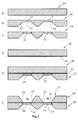
- illustrates the sequence of process steps for the manufacture of the membrane in a first embodiment of the invention,
- Figure 2
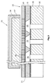
- illustrates a schematic cross section of the first embodiment with the membrane mounted on a support and a heating device being arranged above the membrane, and
- Figure 3
- illustrates a section through a second embodiment of the invention, wherein the first plate is provided with passages.
- In
Figure 1 , afirst plate 10 is illustrated under a), which plate is made of silicon and has a thickness of about 300 µm. This first plate is patterned on one side for instance by photochemical etching using KOH as the etchant, whereby therecesses 11 are formed. With anisotropic KOH etching, he recesses have inclinedflanks 12 and aplanar bottom wall 13 which is parallel to the plane of the plate. In a further step, the thin bottom walls are porosified such that they are pervious to gas. - Under c),
Figure 1 shows that thebottom walls 13 are porosified, whereby they are pervious to gas. Thebottom walls 13, together with the top of the first plate, form a continuous surface as a support for the selectively gas-permeable layer. -
Figure 1d ) illustrates thesecond plate 20 which is also made of silicon and has a thickness of about 300 µm. At first, the second plate is planar and bears the selectively gas-permeable layer 21 on its bottom face, the layer being a thin SiO2 layer of about 12 nm in thickness. Thelayer 21 has grown thermally or has been formed by CVD/ALD deposition. According to the illustration e) inFigure 1 , thesecond plate 20 is placed over thefirst plate 10 and is bonded with the same, for instance by anodic bonding, wherein thelayer 21 lies on thefirst plate 10 with its entire surface. - Under f), it is illustrated that the
second plate 20 is provided with throughholes 22 having inclinedlateral flanks 23. The through holes extend through the entire silicon layer, but not through thelayer 21 of SiO2. - The entire membrane is formed by a
membrane body 25 made up by theplates windows 26 in which the selectively gas-permeable layer 21 is exposed on one side and is supported on the opposite side by theporous bottom wall 13. - The selectively gas-
permeable layer 21 is made from a silicon material, such as quartz, quartz glass, Pyrex glass, silicon oxide, silicon nitride, silicon oxynitride, or silicon carbide. This enumeration only gives examples and is not comprehensive. With such a thin layer, heavy gases can be blocked and light gases can be allowed to pass. Among such light gases are hydrogen and helium. Therefore, the membrane is particularly well suited for leak detectors, e.g. sniffer detectors, which operate with hydrogen or helium as the tracer gas. -
Figure 2 illustrates the device of the first embodiment in the assembled state. Themembrane body 25 is fastened on a supportingbody 30 provided withpump openings 31 that are connected to a vacuum pump means (not illustrated). - Arranged at a distance from the
second plate 20 of themembrane body 25 is aheating device 35 including aheating body 36 made from graphite and silicon carbide or another ceramic material. Theheating body 36 is enclosed by areflector 37 that directs the heat generated towards themembrane body 25, whereby thelayer 21 is heated. The radiation heat is absorbed by all of themembrane body 25 and transferred to thelayer 21. At the interface between themembrane body 25 and the supportingbody 30, aheat reflecting layer 38 is provided that may consist of a layer of metal, preferably of gold. - The embodiment of
Figure 3 differs from the first embodiment only in respectively different structures of thefirst plate 10 and thesecond plate 20. Thelayer 21 that forms the bottom face of thesecond plate 20 is exposed towards thefirst plate 10 in the region of thewindows 26. On the other hand, thesecond plate 20 hasrecesses 40 extending through the silicon layer of the first plate but not penetrating thelayer 21. Therecesses 40 are fine holes with a diameter between 2 nm and 100 nm which may be made by electrochemical etching (anodization). The layer thickness of thelayer 21 is 10 to 21 nm. - In the second embodiment, the
layer 21 is supported at the top by the silicon of thesecond plate 20, whereas in the first embodiment (Figure 2 ) the support is provided at the bottom face of thefirst plate 10. -
Figure 3 also shows aheat reflecting layer 38 between the supportingbody 30 and themembrane body 25. Likewise, theheating device 35 is arranged opposite thesecond plate 20 and includes aheating body 36 and areflector 37. - Although the invention has been described and illustrated with reference to specific illustrative embodiments thereof, it is not intended that the invention be limited to those illustrative embodiments. Those skilled in the art will recognize that variations and modifications can be made without departing from the true scope of the invention as defined by the claims that follow. It is therefore intended to include within the invention all such variations and modifications as fall within the scope of the appended claims and equivalents thereof.
- Further aspects are:
- 1. A method for the manufacture of a membrane having gas-permeable windows (26), the method comprising the following steps:
- manufacturing a first plate (10) from silicon,
- forming recesses (11) or passages in the first plate (10),
- applying a second silicon plate (20) comprising a selectively gas-permeable layer (21) of a silicon material onto the first plate (10),
- forming recesses (22, 40) in the second plate (20), wherein the recesses in the second plate are at least partially overlapping with the recesses (11) or passages in the first plate, such that both plates (10, 20) form a membrane body (25) with windows (26) that each include the selectively gas-permeable layer (21).
- 2. The method according to 1, wherein the forming of recesses or through holes is done by etching, respectively.
- 3. The method according to 2, wherein the gas-selective layer (21) is made of SiO2 and forms a bottom wall of the second plate (20).
- 4. The method according to 1, wherein all recesses (11) of the first plate (10) comprise bottom walls that are porosified and pervious to gas.
- 5. A gas-selective membrane with a membrane body (25) comprising:
- a lower first plate (10) of silicon having recesses (11) or passages, and
- an upper second plate (20) of silicon having passages (22, 40) covered by a bottom wall of a thin gas-selective layer (21), the plates (10, 20) abutting each other in a planar manner.
- 6. The gas-selective membrane according to 5, wherein the recesses (11) of the first plate (10) have porous bottom walls (13).
Claims (3)
- A gas-selective membrane with a membrane body (25) having selectively gas-permeable windows (26) in which a layer (21) of silicon material is situated, and a heating device (35) for heating the windows (26), wherein the heating device (35) is formed by a radiation heating element heating a plurality of windows (26) together, the membrane body (25) serving as a radiation absorber.
- The membrane of claim 1, wherein the heating body (36) comprises an electrically heatable body.
- The membrane of claim 1, wherein the membrane body (25) comprises a heat reflecting layer (38).
Applications Claiming Priority (2)
| Application Number | Priority Date | Filing Date | Title |
|---|---|---|---|
| US12/757,611 US8361196B2 (en) | 2010-04-09 | 2010-04-09 | Gas-selective membrane and method of its production |
| EP11712856.1A EP2556358B1 (en) | 2010-04-09 | 2011-04-06 | A gas-selective membrane and method of its production |
Related Parent Applications (2)
| Application Number | Title | Priority Date | Filing Date |
|---|---|---|---|
| EP11712856.1A Division EP2556358B1 (en) | 2010-04-09 | 2011-04-06 | A gas-selective membrane and method of its production |
| EP11712856.1A Division-Into EP2556358B1 (en) | 2010-04-09 | 2011-04-06 | A gas-selective membrane and method of its production |
Publications (2)
| Publication Number | Publication Date |
|---|---|
| EP3029446A1 true EP3029446A1 (en) | 2016-06-08 |
| EP3029446B1 EP3029446B1 (en) | 2017-09-27 |
Family
ID=44065638
Family Applications (2)
| Application Number | Title | Priority Date | Filing Date |
|---|---|---|---|
| EP16152458.2A Active EP3029446B1 (en) | 2010-04-09 | 2011-04-06 | A gas-selective membrane and method of its production |
| EP11712856.1A Active EP2556358B1 (en) | 2010-04-09 | 2011-04-06 | A gas-selective membrane and method of its production |
Family Applications After (1)
| Application Number | Title | Priority Date | Filing Date |
|---|---|---|---|
| EP11712856.1A Active EP2556358B1 (en) | 2010-04-09 | 2011-04-06 | A gas-selective membrane and method of its production |
Country Status (7)
| Country | Link |
|---|---|
| US (2) | US8361196B2 (en) |
| EP (2) | EP3029446B1 (en) |
| JP (1) | JP5758981B2 (en) |
| KR (1) | KR101811694B1 (en) |
| CN (1) | CN102884409B (en) |
| RU (1) | RU2558644C2 (en) |
| WO (1) | WO2011124618A1 (en) |
Families Citing this family (5)
| Publication number | Priority date | Publication date | Assignee | Title |
|---|---|---|---|---|
| JP5518039B2 (en) * | 2011-12-28 | 2014-06-11 | 株式会社日立製作所 | Filter and manufacturing method thereof |
| KR101759093B1 (en) * | 2015-07-01 | 2017-07-18 | 서울대학교산학협력단 | Nanopore structure, ionic device using nanopore structure and method of manufacturing nanomembrane structure |
| JP6929277B2 (en) * | 2015-10-16 | 2021-09-01 | インフィコン・ホールディング・アーゲーInficon Holding Ag | Optical detection of tracer gas in a gas discharge cell with unexposed electrodes |
| DE102020116939A1 (en) * | 2020-06-26 | 2021-12-30 | Inficon Gmbh | Test leak device |
| DE102021134647A1 (en) * | 2021-12-23 | 2023-06-29 | Inficon Gmbh | Vacuum leak detector with spray-on membrane test leak and method |
Citations (3)
| Publication number | Priority date | Publication date | Assignee | Title |
|---|---|---|---|---|
| EP0831964A1 (en) * | 1995-06-10 | 1998-04-01 | Leybold Vakuum GmbH | Gas passage with selectively acting penetration surface and process for producing the penetration surface |
| WO2002090917A2 (en) * | 2001-05-10 | 2002-11-14 | Inficon Gmbh | Test-leakage device |
| WO2006069876A1 (en) * | 2004-12-23 | 2006-07-06 | Inficon Gmbh | Selective gas sensor |
Family Cites Families (25)
| Publication number | Priority date | Publication date | Assignee | Title |
|---|---|---|---|---|
| US3274750A (en) * | 1962-12-28 | 1966-09-27 | Gen Electric | Permeable polymeric membrane gas separation |
| DE1648367A1 (en) * | 1967-06-05 | 1971-04-15 | Varian Mat Gmbh | Diffusion membrane arrangement, especially for leak detection tubes |
| US3880684A (en) * | 1973-08-03 | 1975-04-29 | Mitsubishi Electric Corp | Process for preparing semiconductor |
| US4384919A (en) * | 1978-11-13 | 1983-05-24 | Sperry Corporation | Method of making x-ray masks |
| US5335256A (en) * | 1991-03-18 | 1994-08-02 | Canon Kabushiki Kaisha | Semiconductor substrate including a single or multi-layer film having different densities in the thickness direction |
| DE4326265A1 (en) * | 1993-08-05 | 1995-02-09 | Leybold Ag | Test gas detector, preferably for leak detection devices, and method for operating a test gas detector of this type |
| CA2351325A1 (en) * | 1998-12-02 | 2000-06-08 | Aleksander J. Franz | Integrated palladium-based micromembranes for hydrogen separation and hydrogenation/dehydrogenation reactions |
| EP1202791B1 (en) * | 1999-06-11 | 2006-12-27 | Gas Separation Technology, Inc. | Porous gas permeable material for gas separation |
| US6784485B1 (en) * | 2000-02-11 | 2004-08-31 | International Business Machines Corporation | Diffusion barrier layer and semiconductor device containing same |
| US6405066B1 (en) * | 2000-03-17 | 2002-06-11 | The Regents Of The University Of California | Implantable analyte sensor |
| DE10162126A1 (en) * | 2001-12-18 | 2003-07-03 | Inficon Gmbh | Gas passage with selective gas passage areas |
| EP1972373A1 (en) * | 2002-07-25 | 2008-09-24 | Dai Nippon Insatsu Kabushiki Kaisha | Production method of hydrogen production filter |
| JP4027218B2 (en) * | 2002-12-13 | 2007-12-26 | キヤノン株式会社 | Filtration membrane manufacturing method |
| ITTO20030032A1 (en) * | 2003-01-24 | 2004-07-25 | Varian Spa | SELECTIVELY GAS PERMEABLE MEMBRANE AND METHOD FOR ITS REALIZATION. |
| US7393391B2 (en) * | 2003-10-24 | 2008-07-01 | Stc.Unm | Fabrication of an anisotropic super hydrophobic/hydrophilic nanoporous membranes |
| US7303681B2 (en) * | 2003-11-18 | 2007-12-04 | Exxonmobil Research And Engineering Company | Dynamic membrane wafer assembly and method |
| US7622086B2 (en) * | 2004-01-26 | 2009-11-24 | Ngk Insulators, Ltd. | Selectively permeable membrane type reactor |
| JP5015766B2 (en) * | 2005-02-04 | 2012-08-29 | 日本碍子株式会社 | Permselective membrane reactor |
| JP4562565B2 (en) * | 2005-03-23 | 2010-10-13 | 株式会社ノリタケカンパニーリミテド | Inorganic porous separation membrane and method for producing the same |
| US7604690B2 (en) * | 2005-04-05 | 2009-10-20 | Wostec, Inc. | Composite material for ultra thin membranes |
| WO2006119252A2 (en) * | 2005-04-29 | 2006-11-09 | University Of Rochester | Ultrathin nanoscale membranes, methods of making, and uses thereof |
| EP1874443A4 (en) * | 2005-04-29 | 2009-09-16 | Univ Rochester | ULTRAFINE NANOPOROUS MEMBRANES, METHOD OF MANUFACTURE AND USES THEREOF |
| DE102006026125A1 (en) * | 2006-06-03 | 2007-12-06 | Inficon Gmbh | gas sensor |
| US8043418B2 (en) * | 2006-12-08 | 2011-10-25 | General Electric Company | Gas separator apparatus |
| RU2422942C1 (en) * | 2009-12-25 | 2011-06-27 | Открытое акционерное общество "Научно-исследовательский институт "Элпа" с опытным производством" (ОАО "НИИ "Элпа") | Method of making membrane structures |
-
2010
- 2010-04-09 US US12/757,611 patent/US8361196B2/en active Active
-
2011
- 2011-04-06 WO PCT/EP2011/055371 patent/WO2011124618A1/en not_active Ceased
- 2011-04-06 EP EP16152458.2A patent/EP3029446B1/en active Active
- 2011-04-06 JP JP2013503102A patent/JP5758981B2/en active Active
- 2011-04-06 KR KR1020127029149A patent/KR101811694B1/en active Active
- 2011-04-06 RU RU2012147519/28A patent/RU2558644C2/en active
- 2011-04-06 EP EP11712856.1A patent/EP2556358B1/en active Active
- 2011-04-06 CN CN201180015925.8A patent/CN102884409B/en active Active
-
2012
- 2012-08-10 US US13/571,851 patent/US8425672B2/en active Active
Patent Citations (5)
| Publication number | Priority date | Publication date | Assignee | Title |
|---|---|---|---|---|
| EP0831964A1 (en) * | 1995-06-10 | 1998-04-01 | Leybold Vakuum GmbH | Gas passage with selectively acting penetration surface and process for producing the penetration surface |
| US6277177B1 (en) | 1995-06-10 | 2001-08-21 | Leybold Vakuum Gmbh | Gas passage with selectively acting penetration surface and process for producing the penetration surface |
| EP0831964B1 (en) | 1995-06-10 | 2004-03-17 | Leybold Vakuum GmbH | Process for producing a gas passage with selectively acting penetration surface and gas passage produced by said process |
| WO2002090917A2 (en) * | 2001-05-10 | 2002-11-14 | Inficon Gmbh | Test-leakage device |
| WO2006069876A1 (en) * | 2004-12-23 | 2006-07-06 | Inficon Gmbh | Selective gas sensor |
Also Published As
| Publication number | Publication date |
|---|---|
| US8425672B2 (en) | 2013-04-23 |
| EP2556358A1 (en) | 2013-02-13 |
| JP2013524228A (en) | 2013-06-17 |
| RU2012147519A (en) | 2014-05-20 |
| CN102884409A (en) | 2013-01-16 |
| US20120304863A1 (en) | 2012-12-06 |
| WO2011124618A1 (en) | 2011-10-13 |
| US8361196B2 (en) | 2013-01-29 |
| US20110247498A1 (en) | 2011-10-13 |
| KR101811694B1 (en) | 2018-01-25 |
| EP2556358B1 (en) | 2017-08-30 |
| JP5758981B2 (en) | 2015-08-05 |
| CN102884409B (en) | 2015-08-19 |
| RU2558644C2 (en) | 2015-08-10 |
| KR20130048729A (en) | 2013-05-10 |
| EP3029446B1 (en) | 2017-09-27 |
Similar Documents
| Publication | Publication Date | Title |
|---|---|---|
| EP3029446B1 (en) | A gas-selective membrane and method of its production | |
| Xu et al. | Low-temperature direct bonding of glass nanofluidic chips using a two-step plasma surface activation process | |
| CN101917784B (en) | Three-dimensional micro heater with groove-shaped heating film region and manufacturing method thereof | |
| US8132455B2 (en) | Robust micromachined thermal mass flow sensor with double side passivated polyimide membrane | |
| CN102730622B (en) | Integrated chip of micro thermal conductive detector and manufacturing method for same | |
| JP6345421B2 (en) | Gas barrier property evaluation apparatus and evaluation method | |
| JP3955323B2 (en) | Gas channel having selectively permeable surface and method for producing the permeable surface | |
| US20110252882A1 (en) | Robust sensor with top cap | |
| CN1657401B (en) | Micromachine semiconductor element and manufacturing method thereof | |
| CN107345826A (en) | A thermal gas flow sensor and its preparation method | |
| CN105738038A (en) | Molecular flow standard leak hole and manufacturing method thereof | |
| CN104828771A (en) | Micro thermal conductivity detector with integrated filtering structure and manufacturing method | |
| CN101443659A (en) | Three-chip channel structure for fluid analyzers | |
| JP4511199B2 (en) | Gas selective permeable membrane and method for producing the same | |
| CN108254031B (en) | Differential pressure gas micro-flow sensor and manufacturing method thereof | |
| CN108271282A (en) | A kind of low-grade fever disk and preparation method thereof | |
| EP2172753B1 (en) | A method for manufacturing infrared sensor on a wafer basis | |
| KR102653650B1 (en) | Methods for manufacturing one or more membrane devices, membrane devices for micromechanical sensors, and components | |
| CN102621026A (en) | Thin film acoustic wave resonance biochemical sensor integrating microchannel | |
| CN113433191B (en) | Annular heating type gas sensor and preparation method thereof | |
| US7703313B2 (en) | Conformal film micro-channels for a fluidic micro analyzer | |
| Tian et al. | Thick and thermally isolated Si microheaters for microfabricated preconcentrators | |
| JPWO2012077325A1 (en) | Silicon structure, array substrate using the same, and method for manufacturing silicon structure | |
| Lysko et al. | Silicon katarometer with the BSC-type contacts | |
| Ye et al. | MEMS-based thin palladium membrane microreactors |
Legal Events
| Date | Code | Title | Description |
|---|---|---|---|
| PUAI | Public reference made under article 153(3) epc to a published international application that has entered the european phase |
Free format text: ORIGINAL CODE: 0009012 |
|
| AC | Divisional application: reference to earlier application |
Ref document number: 2556358 Country of ref document: EP Kind code of ref document: P |
|
| AK | Designated contracting states |
Kind code of ref document: A1 Designated state(s): AL AT BE BG CH CY CZ DE DK EE ES FI FR GB GR HR HU IE IS IT LI LT LU LV MC MK MT NL NO PL PT RO RS SE SI SK SM TR |
|
| STAA | Information on the status of an ep patent application or granted ep patent |
Free format text: STATUS: REQUEST FOR EXAMINATION WAS MADE |
|
| 17P | Request for examination filed |
Effective date: 20161201 |
|
| RBV | Designated contracting states (corrected) |
Designated state(s): AL AT BE BG CH CY CZ DE DK EE ES FI FR GB GR HR HU IE IS IT LI LT LU LV MC MK MT NL NO PL PT RO RS SE SI SK SM TR |
|
| GRAP | Despatch of communication of intention to grant a patent |
Free format text: ORIGINAL CODE: EPIDOSNIGR1 |
|
| STAA | Information on the status of an ep patent application or granted ep patent |
Free format text: STATUS: GRANT OF PATENT IS INTENDED |
|
| INTG | Intention to grant announced |
Effective date: 20170411 |
|
| GRAS | Grant fee paid |
Free format text: ORIGINAL CODE: EPIDOSNIGR3 |
|
| GRAA | (expected) grant |
Free format text: ORIGINAL CODE: 0009210 |
|
| STAA | Information on the status of an ep patent application or granted ep patent |
Free format text: STATUS: THE PATENT HAS BEEN GRANTED |
|
| AC | Divisional application: reference to earlier application |
Ref document number: 2556358 Country of ref document: EP Kind code of ref document: P |
|
| AK | Designated contracting states |
Kind code of ref document: B1 Designated state(s): AL AT BE BG CH CY CZ DE DK EE ES FI FR GB GR HR HU IE IS IT LI LT LU LV MC MK MT NL NO PL PT RO RS SE SI SK SM TR |
|
| REG | Reference to a national code |
Ref country code: GB Ref legal event code: FG4D |
|
| REG | Reference to a national code |
Ref country code: CH Ref legal event code: EP |
|
| REG | Reference to a national code |
Ref country code: AT Ref legal event code: REF Ref document number: 932384 Country of ref document: AT Kind code of ref document: T Effective date: 20171015 |
|
| REG | Reference to a national code |
Ref country code: IE Ref legal event code: FG4D |
|
| REG | Reference to a national code |
Ref country code: DE Ref legal event code: R096 Ref document number: 602011042042 Country of ref document: DE |
|
| PG25 | Lapsed in a contracting state [announced via postgrant information from national office to epo] |
Ref country code: HR Free format text: LAPSE BECAUSE OF FAILURE TO SUBMIT A TRANSLATION OF THE DESCRIPTION OR TO PAY THE FEE WITHIN THE PRESCRIBED TIME-LIMIT Effective date: 20170927 Ref country code: NO Free format text: LAPSE BECAUSE OF FAILURE TO SUBMIT A TRANSLATION OF THE DESCRIPTION OR TO PAY THE FEE WITHIN THE PRESCRIBED TIME-LIMIT Effective date: 20171227 Ref country code: FI Free format text: LAPSE BECAUSE OF FAILURE TO SUBMIT A TRANSLATION OF THE DESCRIPTION OR TO PAY THE FEE WITHIN THE PRESCRIBED TIME-LIMIT Effective date: 20170927 Ref country code: LT Free format text: LAPSE BECAUSE OF FAILURE TO SUBMIT A TRANSLATION OF THE DESCRIPTION OR TO PAY THE FEE WITHIN THE PRESCRIBED TIME-LIMIT Effective date: 20170927 Ref country code: SE Free format text: LAPSE BECAUSE OF FAILURE TO SUBMIT A TRANSLATION OF THE DESCRIPTION OR TO PAY THE FEE WITHIN THE PRESCRIBED TIME-LIMIT Effective date: 20170927 |
|
| REG | Reference to a national code |
Ref country code: NL Ref legal event code: MP Effective date: 20170927 |
|
| REG | Reference to a national code |
Ref country code: LT Ref legal event code: MG4D |
|
| REG | Reference to a national code |
Ref country code: AT Ref legal event code: MK05 Ref document number: 932384 Country of ref document: AT Kind code of ref document: T Effective date: 20170927 |
|
| PG25 | Lapsed in a contracting state [announced via postgrant information from national office to epo] |
Ref country code: LV Free format text: LAPSE BECAUSE OF FAILURE TO SUBMIT A TRANSLATION OF THE DESCRIPTION OR TO PAY THE FEE WITHIN THE PRESCRIBED TIME-LIMIT Effective date: 20170927 Ref country code: GR Free format text: LAPSE BECAUSE OF FAILURE TO SUBMIT A TRANSLATION OF THE DESCRIPTION OR TO PAY THE FEE WITHIN THE PRESCRIBED TIME-LIMIT Effective date: 20171228 Ref country code: RS Free format text: LAPSE BECAUSE OF FAILURE TO SUBMIT A TRANSLATION OF THE DESCRIPTION OR TO PAY THE FEE WITHIN THE PRESCRIBED TIME-LIMIT Effective date: 20170927 Ref country code: BG Free format text: LAPSE BECAUSE OF FAILURE TO SUBMIT A TRANSLATION OF THE DESCRIPTION OR TO PAY THE FEE WITHIN THE PRESCRIBED TIME-LIMIT Effective date: 20171227 |
|
| PG25 | Lapsed in a contracting state [announced via postgrant information from national office to epo] |
Ref country code: NL Free format text: LAPSE BECAUSE OF FAILURE TO SUBMIT A TRANSLATION OF THE DESCRIPTION OR TO PAY THE FEE WITHIN THE PRESCRIBED TIME-LIMIT Effective date: 20170927 |
|
| REG | Reference to a national code |
Ref country code: FR Ref legal event code: PLFP Year of fee payment: 8 |
|
| PG25 | Lapsed in a contracting state [announced via postgrant information from national office to epo] |
Ref country code: CZ Free format text: LAPSE BECAUSE OF FAILURE TO SUBMIT A TRANSLATION OF THE DESCRIPTION OR TO PAY THE FEE WITHIN THE PRESCRIBED TIME-LIMIT Effective date: 20170927 Ref country code: RO Free format text: LAPSE BECAUSE OF FAILURE TO SUBMIT A TRANSLATION OF THE DESCRIPTION OR TO PAY THE FEE WITHIN THE PRESCRIBED TIME-LIMIT Effective date: 20170927 Ref country code: ES Free format text: LAPSE BECAUSE OF FAILURE TO SUBMIT A TRANSLATION OF THE DESCRIPTION OR TO PAY THE FEE WITHIN THE PRESCRIBED TIME-LIMIT Effective date: 20170927 |
|
| PG25 | Lapsed in a contracting state [announced via postgrant information from national office to epo] |
Ref country code: IS Free format text: LAPSE BECAUSE OF FAILURE TO SUBMIT A TRANSLATION OF THE DESCRIPTION OR TO PAY THE FEE WITHIN THE PRESCRIBED TIME-LIMIT Effective date: 20180127 Ref country code: SM Free format text: LAPSE BECAUSE OF FAILURE TO SUBMIT A TRANSLATION OF THE DESCRIPTION OR TO PAY THE FEE WITHIN THE PRESCRIBED TIME-LIMIT Effective date: 20170927 Ref country code: AT Free format text: LAPSE BECAUSE OF FAILURE TO SUBMIT A TRANSLATION OF THE DESCRIPTION OR TO PAY THE FEE WITHIN THE PRESCRIBED TIME-LIMIT Effective date: 20170927 Ref country code: EE Free format text: LAPSE BECAUSE OF FAILURE TO SUBMIT A TRANSLATION OF THE DESCRIPTION OR TO PAY THE FEE WITHIN THE PRESCRIBED TIME-LIMIT Effective date: 20170927 Ref country code: SK Free format text: LAPSE BECAUSE OF FAILURE TO SUBMIT A TRANSLATION OF THE DESCRIPTION OR TO PAY THE FEE WITHIN THE PRESCRIBED TIME-LIMIT Effective date: 20170927 |
|
| REG | Reference to a national code |
Ref country code: DE Ref legal event code: R097 Ref document number: 602011042042 Country of ref document: DE |
|
| PG25 | Lapsed in a contracting state [announced via postgrant information from national office to epo] |
Ref country code: DK Free format text: LAPSE BECAUSE OF FAILURE TO SUBMIT A TRANSLATION OF THE DESCRIPTION OR TO PAY THE FEE WITHIN THE PRESCRIBED TIME-LIMIT Effective date: 20170927 |
|
| PLBE | No opposition filed within time limit |
Free format text: ORIGINAL CODE: 0009261 |
|
| STAA | Information on the status of an ep patent application or granted ep patent |
Free format text: STATUS: NO OPPOSITION FILED WITHIN TIME LIMIT |
|
| PG25 | Lapsed in a contracting state [announced via postgrant information from national office to epo] |
Ref country code: PL Free format text: LAPSE BECAUSE OF FAILURE TO SUBMIT A TRANSLATION OF THE DESCRIPTION OR TO PAY THE FEE WITHIN THE PRESCRIBED TIME-LIMIT Effective date: 20170927 |
|
| 26N | No opposition filed |
Effective date: 20180628 |
|
| PG25 | Lapsed in a contracting state [announced via postgrant information from national office to epo] |
Ref country code: MC Free format text: LAPSE BECAUSE OF FAILURE TO SUBMIT A TRANSLATION OF THE DESCRIPTION OR TO PAY THE FEE WITHIN THE PRESCRIBED TIME-LIMIT Effective date: 20170927 Ref country code: SI Free format text: LAPSE BECAUSE OF FAILURE TO SUBMIT A TRANSLATION OF THE DESCRIPTION OR TO PAY THE FEE WITHIN THE PRESCRIBED TIME-LIMIT Effective date: 20170927 |
|
| REG | Reference to a national code |
Ref country code: CH Ref legal event code: PL |
|
| REG | Reference to a national code |
Ref country code: BE Ref legal event code: MM Effective date: 20180430 |
|
| GBPC | Gb: european patent ceased through non-payment of renewal fee |
Effective date: 20180406 |
|
| REG | Reference to a national code |
Ref country code: IE Ref legal event code: MM4A |
|
| PG25 | Lapsed in a contracting state [announced via postgrant information from national office to epo] |
Ref country code: LU Free format text: LAPSE BECAUSE OF NON-PAYMENT OF DUE FEES Effective date: 20180406 |
|
| PG25 | Lapsed in a contracting state [announced via postgrant information from national office to epo] |
Ref country code: BE Free format text: LAPSE BECAUSE OF NON-PAYMENT OF DUE FEES Effective date: 20180430 Ref country code: GB Free format text: LAPSE BECAUSE OF NON-PAYMENT OF DUE FEES Effective date: 20180406 Ref country code: LI Free format text: LAPSE BECAUSE OF NON-PAYMENT OF DUE FEES Effective date: 20180430 Ref country code: CH Free format text: LAPSE BECAUSE OF NON-PAYMENT OF DUE FEES Effective date: 20180430 |
|
| PG25 | Lapsed in a contracting state [announced via postgrant information from national office to epo] |
Ref country code: IE Free format text: LAPSE BECAUSE OF NON-PAYMENT OF DUE FEES Effective date: 20180406 |
|
| PG25 | Lapsed in a contracting state [announced via postgrant information from national office to epo] |
Ref country code: MT Free format text: LAPSE BECAUSE OF NON-PAYMENT OF DUE FEES Effective date: 20180406 |
|
| PG25 | Lapsed in a contracting state [announced via postgrant information from national office to epo] |
Ref country code: TR Free format text: LAPSE BECAUSE OF FAILURE TO SUBMIT A TRANSLATION OF THE DESCRIPTION OR TO PAY THE FEE WITHIN THE PRESCRIBED TIME-LIMIT Effective date: 20170927 |
|
| PG25 | Lapsed in a contracting state [announced via postgrant information from national office to epo] |
Ref country code: PT Free format text: LAPSE BECAUSE OF FAILURE TO SUBMIT A TRANSLATION OF THE DESCRIPTION OR TO PAY THE FEE WITHIN THE PRESCRIBED TIME-LIMIT Effective date: 20170927 |
|
| PG25 | Lapsed in a contracting state [announced via postgrant information from national office to epo] |
Ref country code: HU Free format text: LAPSE BECAUSE OF FAILURE TO SUBMIT A TRANSLATION OF THE DESCRIPTION OR TO PAY THE FEE WITHIN THE PRESCRIBED TIME-LIMIT; INVALID AB INITIO Effective date: 20110406 Ref country code: MK Free format text: LAPSE BECAUSE OF NON-PAYMENT OF DUE FEES Effective date: 20170927 Ref country code: CY Free format text: LAPSE BECAUSE OF FAILURE TO SUBMIT A TRANSLATION OF THE DESCRIPTION OR TO PAY THE FEE WITHIN THE PRESCRIBED TIME-LIMIT Effective date: 20170927 |
|
| PG25 | Lapsed in a contracting state [announced via postgrant information from national office to epo] |
Ref country code: AL Free format text: LAPSE BECAUSE OF FAILURE TO SUBMIT A TRANSLATION OF THE DESCRIPTION OR TO PAY THE FEE WITHIN THE PRESCRIBED TIME-LIMIT Effective date: 20170927 |
|
| REG | Reference to a national code |
Ref country code: DE Ref legal event code: R082 Ref document number: 602011042042 Country of ref document: DE Representative=s name: DOMPATENT VON KREISLER SELTING WERNER - PARTNE, DE Ref country code: DE Ref legal event code: R081 Ref document number: 602011042042 Country of ref document: DE Owner name: INFICON HOLDING AG, CH Free format text: FORMER OWNER: INFICON GMBH, BAD RAGAZ, CH |
|
| P01 | Opt-out of the competence of the unified patent court (upc) registered |
Effective date: 20230427 |
|
| PGFP | Annual fee paid to national office [announced via postgrant information from national office to epo] |
Ref country code: DE Payment date: 20250415 Year of fee payment: 15 |
|
| PGFP | Annual fee paid to national office [announced via postgrant information from national office to epo] |
Ref country code: IT Payment date: 20250430 Year of fee payment: 15 |
|
| PGFP | Annual fee paid to national office [announced via postgrant information from national office to epo] |
Ref country code: FR Payment date: 20250422 Year of fee payment: 15 |